technical specification fluxus g601technical specification fluxus g601 tsfluxus_g601v2-4en_leu,...
TRANSCRIPT
Technical specification
FLUXUS G601
TSFLUXUS_G601V2-4EN_Leu, 2019-11-01
Features
• Configurable as multifunctional measuring system:
– flow measurement of gases, compressed air and saturated steam up to max. 180 °C
– flow and thermal energy measurement of liquids
• Precise bidirectional and highly dynamic flow measurement with the non-invasive clamp-on technology
• High precision at fast and slow flow rates, high temperature and zero point stability
• Portable, easy-to-use flow transmitter with 2 flow channels, multiple inputs/outputs, an integrated data logger with a serial interface
• Water and dust-tight (IP65); resistant against oil, many liquids and dirt
• Li-Ion battery provides up to 25 hours of measurement opera-tion
• Automatic loading of calibration data and transducer detection for a fast and easy set-up (less than 5 min), providing precise and long-term stable results
• User-friendly design
• Transducers available for a wide range of inner pipe diameters and fluid temperatures
• Probe for wall thickness measurement available
• Robust, water-tight (IP67) transport case with comprehensive accessories
• QuickFix for fast mounting of the flow transmitter in difficult conditions
Applications
Designed for industrial use in harsh environments, applicable inall areas such as maintenance, energy management, trouble-shooting and verification of installed measuring systems. Practi-cal applications
• Data gathering in energy management and certifications ac-cording to ISO 50001
• Supervision and monitoring of compressed air and steam sys-tems
• Hydraulic balancing of cooling towers
• Measurement on natural gas pipelines and in natural gas stor-age installations
• Measurement of synthesized gas and injection gas
• Measurement for the gas supply industry
• Supervision of permanently installed meters, service and main-tenance
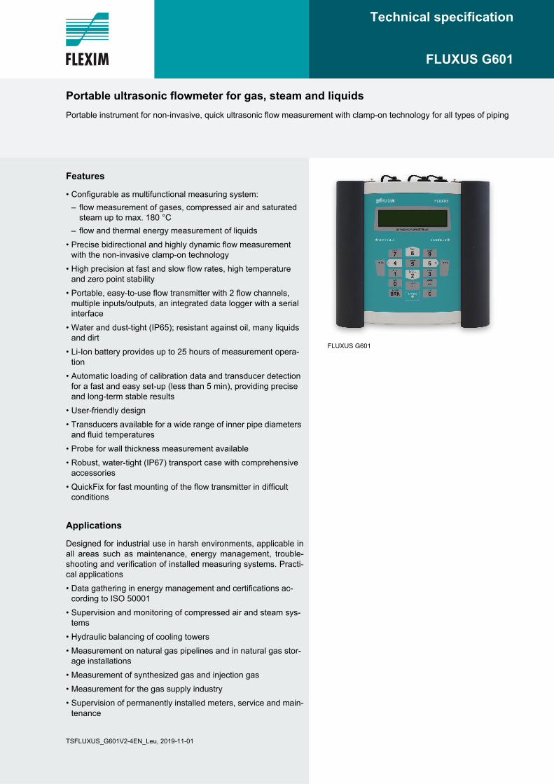
FLUXUS G601
Portable ultrasonic flowmeter for gas, steam and liquids
Portable instrument for non-invasive, quick ultrasonic flow measurement with clamp-on technology for all types of piping
FLUXUS G601 Technical specification
2019-11-01, TSFLUXUS_G601V2-4EN_Leu2
Table of contents
Function . . . . . . . . . . . . . . . . . . . . . . . . . . . . . . . . . . . . . . . . . . . . . . . . . . . . . . . . . . . . . . . . . . . . . . . . . . . . . . . . . . . . . . . 3Measurement principle . . . . . . . . . . . . . . . . . . . . . . . . . . . . . . . . . . . . . . . . . . . . . . . . . . . . . . . . . . . . . . . . . . . . . . . . . . . . . 3Calculation of volumetric flow rate . . . . . . . . . . . . . . . . . . . . . . . . . . . . . . . . . . . . . . . . . . . . . . . . . . . . . . . . . . . . . . . . . . . . 3Calculation of mass flow. . . . . . . . . . . . . . . . . . . . . . . . . . . . . . . . . . . . . . . . . . . . . . . . . . . . . . . . . . . . . . . . . . . . . . . . . . . . 4Number of sound paths . . . . . . . . . . . . . . . . . . . . . . . . . . . . . . . . . . . . . . . . . . . . . . . . . . . . . . . . . . . . . . . . . . . . . . . . . . . . 4Typical measurement setup . . . . . . . . . . . . . . . . . . . . . . . . . . . . . . . . . . . . . . . . . . . . . . . . . . . . . . . . . . . . . . . . . . . . . . . . . 5Standard volumetric flow rate. . . . . . . . . . . . . . . . . . . . . . . . . . . . . . . . . . . . . . . . . . . . . . . . . . . . . . . . . . . . . . . . . . . . . . . . 5
Transmitter . . . . . . . . . . . . . . . . . . . . . . . . . . . . . . . . . . . . . . . . . . . . . . . . . . . . . . . . . . . . . . . . . . . . . . . . . . . . . . . . . . . . . 6Technical data . . . . . . . . . . . . . . . . . . . . . . . . . . . . . . . . . . . . . . . . . . . . . . . . . . . . . . . . . . . . . . . . . . . . . . . . . . . . . . . . . . . 6Saturated steam pressure curve (steam measurement) . . . . . . . . . . . . . . . . . . . . . . . . . . . . . . . . . . . . . . . . . . . . . . . . . . . 7Dimensions. . . . . . . . . . . . . . . . . . . . . . . . . . . . . . . . . . . . . . . . . . . . . . . . . . . . . . . . . . . . . . . . . . . . . . . . . . . . . . . . . . . . . . 8Standard scope of supply. . . . . . . . . . . . . . . . . . . . . . . . . . . . . . . . . . . . . . . . . . . . . . . . . . . . . . . . . . . . . . . . . . . . . . . . . . . 8Adapters . . . . . . . . . . . . . . . . . . . . . . . . . . . . . . . . . . . . . . . . . . . . . . . . . . . . . . . . . . . . . . . . . . . . . . . . . . . . . . . . . . . . . . . . 9
Transducers . . . . . . . . . . . . . . . . . . . . . . . . . . . . . . . . . . . . . . . . . . . . . . . . . . . . . . . . . . . . . . . . . . . . . . . . . . . . . . . . . . . 10Transducer selection (gas measurement) . . . . . . . . . . . . . . . . . . . . . . . . . . . . . . . . . . . . . . . . . . . . . . . . . . . . . . . . . . . . . 10Transducer selection (G**1SC3) . . . . . . . . . . . . . . . . . . . . . . . . . . . . . . . . . . . . . . . . . . . . . . . . . . . . . . . . . . . . . . . . . . . . 13Transducer order code . . . . . . . . . . . . . . . . . . . . . . . . . . . . . . . . . . . . . . . . . . . . . . . . . . . . . . . . . . . . . . . . . . . . . . . . . . . . 14Technical data . . . . . . . . . . . . . . . . . . . . . . . . . . . . . . . . . . . . . . . . . . . . . . . . . . . . . . . . . . . . . . . . . . . . . . . . . . . . . . . . . . 15
Transducer mounting fixture. . . . . . . . . . . . . . . . . . . . . . . . . . . . . . . . . . . . . . . . . . . . . . . . . . . . . . . . . . . . . . . . . . . . . . 19
Coupling materials for transducers . . . . . . . . . . . . . . . . . . . . . . . . . . . . . . . . . . . . . . . . . . . . . . . . . . . . . . . . . . . . . . . . 20
Damping material (optional) . . . . . . . . . . . . . . . . . . . . . . . . . . . . . . . . . . . . . . . . . . . . . . . . . . . . . . . . . . . . . . . . . . . . . . 21Damping mats . . . . . . . . . . . . . . . . . . . . . . . . . . . . . . . . . . . . . . . . . . . . . . . . . . . . . . . . . . . . . . . . . . . . . . . . . . . . . . . . . . 21Damping coat . . . . . . . . . . . . . . . . . . . . . . . . . . . . . . . . . . . . . . . . . . . . . . . . . . . . . . . . . . . . . . . . . . . . . . . . . . . . . . . . . . . 22
Connection systems . . . . . . . . . . . . . . . . . . . . . . . . . . . . . . . . . . . . . . . . . . . . . . . . . . . . . . . . . . . . . . . . . . . . . . . . . . . . 23
Clamp-on temperature probe (optional). . . . . . . . . . . . . . . . . . . . . . . . . . . . . . . . . . . . . . . . . . . . . . . . . . . . . . . . . . . . . 24Technical data . . . . . . . . . . . . . . . . . . . . . . . . . . . . . . . . . . . . . . . . . . . . . . . . . . . . . . . . . . . . . . . . . . . . . . . . . . . . . . . . . . 24Fixation. . . . . . . . . . . . . . . . . . . . . . . . . . . . . . . . . . . . . . . . . . . . . . . . . . . . . . . . . . . . . . . . . . . . . . . . . . . . . . . . . . . . . . . . 25
Wall thickness measurement (optional). . . . . . . . . . . . . . . . . . . . . . . . . . . . . . . . . . . . . . . . . . . . . . . . . . . . . . . . . . . . . 26Technical data . . . . . . . . . . . . . . . . . . . . . . . . . . . . . . . . . . . . . . . . . . . . . . . . . . . . . . . . . . . . . . . . . . . . . . . . . . . . . . . . . . 26
Technical specification FLUXUS G601
3TSFLUXUS_G601V2-4EN_Leu, 2019-11-01
Function
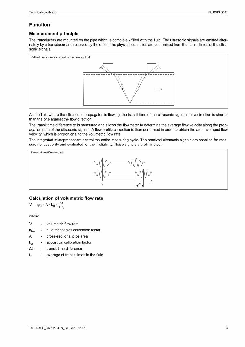
Measurement principleThe transducers are mounted on the pipe which is completely filled with the fluid. The ultrasonic signals are emitted alter-nately by a transducer and received by the other. The physical quantities are determined from the transit times of the ultra-sonic signals.
As the fluid where the ultrasound propagates is flowing, the transit time of the ultrasonic signal in flow direction is shorterthan the one against the flow direction.
The transit time difference Δt is measured and allows the flowmeter to determine the average flow velocity along the prop-agation path of the ultrasonic signals. A flow profile correction is then performed in order to obtain the area averaged flowvelocity, which is proportional to the volumetric flow rate.
The integrated microprocessors control the entire measuring cycle. The received ultrasonic signals are checked for mea-surement usability and evaluated for their reliability. Noise signals are eliminated.
Calculation of volumetric flow rate = kRe · A · ka ·
where
Path of the ultrasonic signal in the flowing fluid
Transit time difference Δt
- volumetric flow rate
kRe - fluid mechanics calibration factor
A - cross-sectional pipe area
ka - acoustical calibration factor
Δt - transit time difference
tγ - average of transit times in the fluid
Δtt0
Vꞏ t2 t-----------
Vꞏ
FLUXUS G601 Technical specification
2019-11-01, TSFLUXUS_G601V2-4EN_Leu4
Calculation of mass flowThe mass flow is calculated on the base of operating density and volume flow:
= ρ .
The operating density of the fluid is calculated as the function of concentration and temperature of the fluid:
ρ = f(K, T)
where
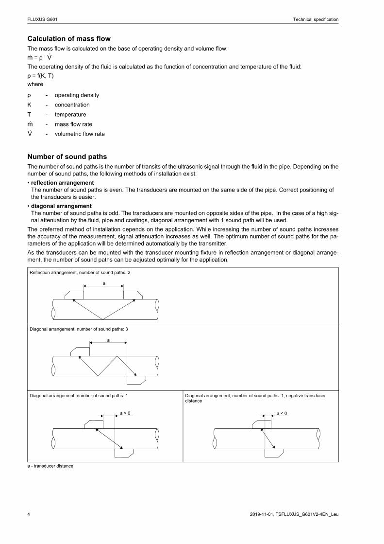
Number of sound pathsThe number of sound paths is the number of transits of the ultrasonic signal through the fluid in the pipe. Depending on thenumber of sound paths, the following methods of installation exist:
• reflection arrangementThe number of sound paths is even. The transducers are mounted on the same side of the pipe. Correct positioning of the transducers is easier.
• diagonal arrangementThe number of sound paths is odd. The transducers are mounted on opposite sides of the pipe. In the case of a high sig-nal attenuation by the fluid, pipe and coatings, diagonal arrangement with 1 sound path will be used.
The preferred method of installation depends on the application. While increasing the number of sound paths increasesthe accuracy of the measurement, signal attenuation increases as well. The optimum number of sound paths for the pa-rameters of the application will be determined automatically by the transmitter.
As the transducers can be mounted with the transducer mounting fixture in reflection arrangement or diagonal arrange-ment, the number of sound paths can be adjusted optimally for the application.
a - transducer distance
ρ - operating density
K - concentration
T - temperature
- mass flow rate
- volumetric flow rate
Reflection arrangement, number of sound paths: 2
Diagonal arrangement, number of sound paths: 3
Diagonal arrangement, number of sound paths: 1 Diagonal arrangement, number of sound paths: 1, negative transducer distance
mꞏ Vꞏ
mꞏ
Vꞏ
a
a
a > 0 a < 0
Technical specification FLUXUS G601
5TSFLUXUS_G601V2-4EN_Leu, 2019-11-01
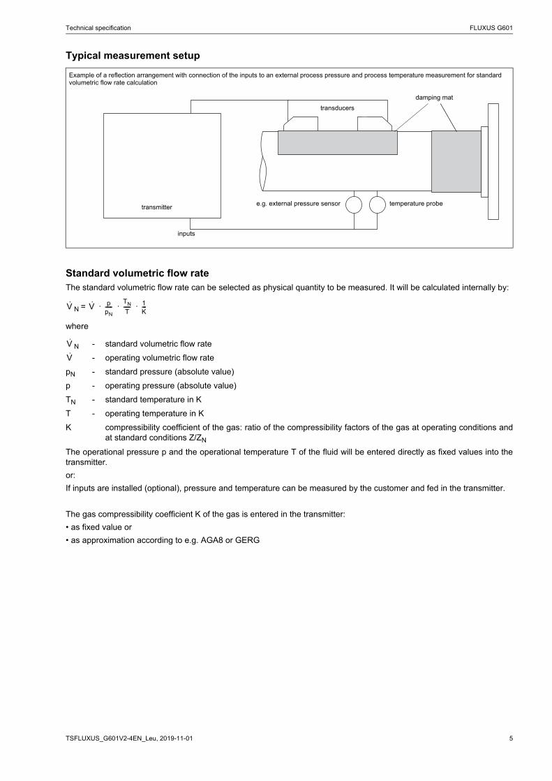
Typical measurement setup
Standard volumetric flow rateThe standard volumetric flow rate can be selected as physical quantity to be measured. It will be calculated internally by:
N = · · ·
where
The operational pressure p and the operational temperature T of the fluid will be entered directly as fixed values into thetransmitter.
or:
If inputs are installed (optional), pressure and temperature can be measured by the customer and fed in the transmitter.
The gas compressibility coefficient K of the gas is entered in the transmitter:
• as fixed value or
• as approximation according to e.g. AGA8 or GERG
Example of a reflection arrangement with connection of the inputs to an external process pressure and process temperature measurement for standard volumetric flow rate calculation
N - standard volumetric flow rate
- operating volumetric flow rate
pN - standard pressure (absolute value)
p - operating pressure (absolute value)
TN - standard temperature in K
T - operating temperature in K
K compressibility coefficient of the gas: ratio of the compressibility factors of the gas at operating conditions andat standard conditions Z/ZN
transducers
damping mat
transmitter
inputs
temperature probee.g. external pressure sensor
Vꞏ Vꞏ ppN-----
TN
T----- 1
K---
Vꞏ
Vꞏ
FLUXUS G601 Technical specification
2019-11-01, TSFLUXUS_G601V2-4EN_Leu6
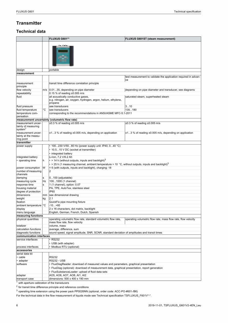
Transmitter
Technical data
FLUXUS G601** FLUXUS G601ST (steam measurement)
design portablemeasurement
test measurement to validate the application required in advan-ce
measurement principle
transit time difference correlation principle
flow velocity m/s 0.01...35, depending on pipe diameter depending on pipe diameter and transducer, see diagramsrepeatability 0.15 % of reading ±0.005 m/sfluid all acoustically conductive gases,
e.g. nitrogen, air, oxygen, hydrogen, argon, helium, ethylene, propane
saturated steam, superheated steam
fluid pressure see transducers 3...10fluid temperature °C see transducers 135...180temperature com-pensation
corresponding to the recommendations in ANSI/ASME MFC-5.1-2011
measurement uncertainty (volumetric flow rate)measurement uncer-tainty of measuring system1
±0.3 % of reading ±0.005 m/s ±0.3 % of reading ±0.005 m/s
measurement uncer-tainty at the measu-ring point
±1...3 % of reading ±0.005 m/s, depending on application ±1...3 % of reading ±0.005 m/s, depending on application
transmitterpower supply • 100...230 V/50...60 Hz (power supply unit: IP40, 0...40 °C)
• 10.5...15 V DC (socket at transmitter)
• integrated batteryintegrated battery Li-Ion, 7.2 V/6.2 Ah• operating time h • > 14 h (without outputs, inputs and backlight)3
• > 25 h (1 measuring channel, ambient temperature > 10 °C, without outputs, inputs and backlight)3
power consumption W < 6 (with outputs, inputs and backlight), charging: 18number of measuring channels
2
damping s 0...100 (adjustable)measuring cycle Hz 100...1000 (1 channel)response time s 1 (1 channel), option: 0.07housing material PA, TPE, AutoTex, stainless steeldegree of protection IP65dimensions mm see dimensional drawingweight kg 2.1fixation QuickFix pipe mounting fixtureambient temperature °C -10...+60display 2 x 16 characters, dot matrix, backlightmenu language English, German, French, Dutch, Spanishmeasuring functionsphysical quantities operating volumetric flow rate, standard volumetric flow rate,
mass flow rate, flow velocityoperating volumetric flow rate, mass flow rate, flow velocity
totalizer volume, masscalculation functions average, difference, sumdiagnostic functions sound speed, signal amplitude, SNR, SCNR, standard deviation of amplitudes and transit timescommunication interfacesservice interfaces • RS232
• USB (with adapter)process interfaces • Modbus RTU (optional)accessoriesserial data kit• сable RS232• adapter RS232 - USBsoftware • FluxDiagReader: download of measured values and parameters, graphical presentation
• FluxDiag (optional): download of measurement data, graphical presentation, report generation
• FluxSubstanceLoader: upload of fluid data setsadapter AO5, AO6, AO7, AO8, AI1, AI2transport case dimensions: 500 x 400 x 190 mm1 with aperture calibration of the transducers2 for transit time difference principle and reference conditions3 operating time extension using the power pack PP0026NN (optional, order code: ACC-PO-#601-/B6)
For the technical data in the flow measurement of liquids mode see Technical specification TSFLUXUS_F601V*-*.
Technical specification FLUXUS G601
7TSFLUXUS_G601V2-4EN_Leu, 2019-11-01
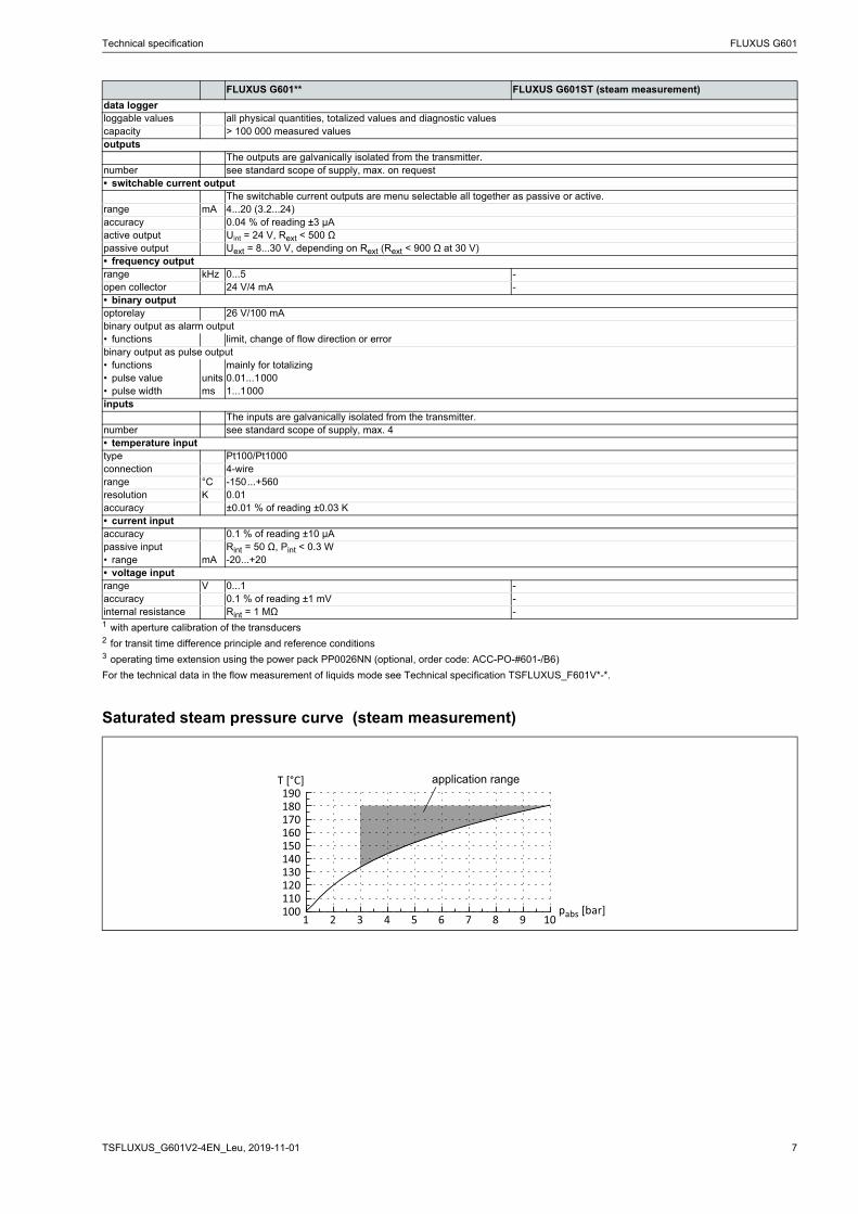
Saturated steam pressure curve (steam measurement)
data loggerloggable values all physical quantities, totalized values and diagnostic valuescapacity > 100 000 measured valuesoutputs
The outputs are galvanically isolated from the transmitter.number see standard scope of supply, max. on request• switchable current output
The switchable current outputs are menu selectable all together as passive or active. range mA 4...20 (3.2...24)accuracy 0.04 % of reading ±3 μAactive output Uint = 24 V, Rext < 500 Ωpassive output Uext = 8...30 V, depending on Rext (Rext < 900 Ω at 30 V)• frequency outputrange kHz 0...5 -open collector 24 V/4 mA -• binary outputoptorelay 26 V/100 mAbinary output as alarm output• functions limit, change of flow direction or errorbinary output as pulse output• functions mainly for totalizing• pulse value units 0.01...1000• pulse width ms 1...1000inputs
The inputs are galvanically isolated from the transmitter.number see standard scope of supply, max. 4• temperature inputtype Pt100/Pt1000connection 4-wirerange °C -150...+560resolution K 0.01accuracy ±0.01 % of reading ±0.03 K• current inputaccuracy 0.1 % of reading ±10 μApassive input Rint = 50 Ω, Pint < 0.3 W• range mA -20...+20• voltage inputrange V 0...1 -accuracy 0.1 % of reading ±1 mV -internal resistance Rint = 1 MΩ -
FLUXUS G601** FLUXUS G601ST (steam measurement)
1 with aperture calibration of the transducers2 for transit time difference principle and reference conditions3 operating time extension using the power pack PP0026NN (optional, order code: ACC-PO-#601-/B6)
For the technical data in the flow measurement of liquids mode see Technical specification TSFLUXUS_F601V*-*.
100110120130140150160170180190
1 32 54 76 98 10
T [°C]
pabs [bar]
application range
FLUXUS G601 Technical specification
2019-11-01, TSFLUXUS_G601V2-4EN_Leu8
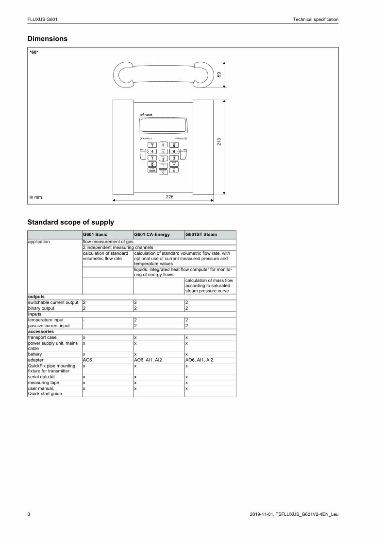
Dimensions
Standard scope of supply
*60*
G601 Basic G601 CA-Energy G601ST Steam
application flow measurement of gas2 independent measuring channelscalculation of standard volumetric flow rate
calculation of standard volumetric flow rate, with optional use of current measured pressure and temperature valuesliquids: integrated heat flow computer for monito-ring of energy flows
calculation of mass flow according to saturated steam pressure curve
outputsswitchable current output 2 2 2binary output 2 2 2inputstemperature input - 2 2passive current input - 2 2accessoriestransport case x x xpower supply unit, mains cable
x x x
battery x x xadapter AO6 AO6, AI1, AI2 AO6, AI1, AI2QuickFix pipe mounting fixture for transmitter
x x x
serial data kit x x xmeasuring tape x x xuser manual,Quick start guide
x x x
CHANNEL BCHANNEL A
BATTERY
1 20
4 5 67
SNAPQ- Q+
MUX
NEXT
9DISP
3DISP
–MODEFAST
.LIGHT
3x OFF
3x QOFF
8QON
ENTER ENTER
BRKON
C
226
59
213
in mm
Technical specification FLUXUS G601
9TSFLUXUS_G601V2-4EN_Leu, 2019-11-01
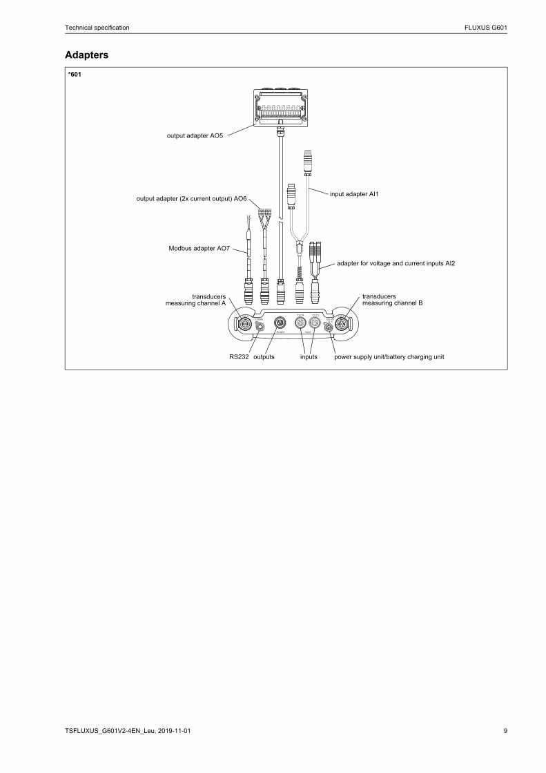
Adapters
*601
CH ACOMM
Input
T2/T4 T1/T3
Output
CH BDC-IN12 V
-P1+-P2+-P3+-P4+-P5+-P6+-P7+-P8+
1 2
output adapter AO5
input adapter AI1
adapter for voltage and current inputs AI2
transducersmeasuring channel A
outputs inputs
transducersmeasuring channel B
power supply unit/battery charging unitRS232
Modbus adapter AO7
output adapter (2x current output) AO6
FLUXUS G601 Technical specification
2019-11-01, TSFLUXUS_G601V2-4EN_Leu10
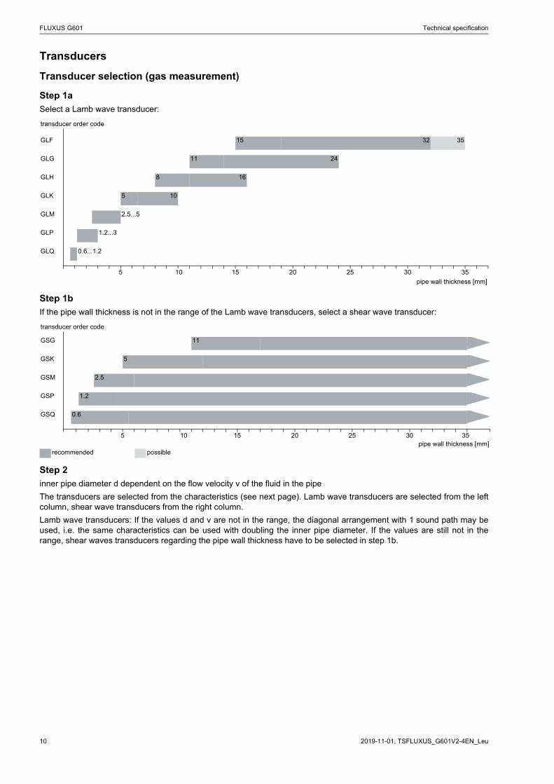
Transducers
Transducer selection (gas measurement)
Step 1a
Select a Lamb wave transducer:
Step 1b
If the pipe wall thickness is not in the range of the Lamb wave transducers, select a shear wave transducer:
Step 2
inner pipe diameter d dependent on the flow velocity v of the fluid in the pipe
The transducers are selected from the characteristics (see next page). Lamb wave transducers are selected from the leftcolumn, shear wave transducers from the right column.
Lamb wave transducers: If the values d and v are not in the range, the diagonal arrangement with 1 sound path may beused, i.e. the same characteristics can be used with doubling the inner pipe diameter. If the values are still not in therange, shear waves transducers regarding the pipe wall thickness have to be selected in step 1b.
transducer order code
GLF 15 32 35
GLG 11 24
GLH 8 16
GLK 5 10
GLM 2.5...5
GLP 1.2...3
GLQ 0.6...1.2
5 10 15 20 25 30 35
pipe wall thickness [mm]
transducer order code
GSG 11
GSK 5
GSM 2.5
GSP 1.2
GSQ 0.6
5 10 15 20 25 30 35pipe wall thickness [mm]
recommended possible
Technical specification FLUXUS G601
11TSFLUXUS_G601V2-4EN_Leu, 2019-11-01
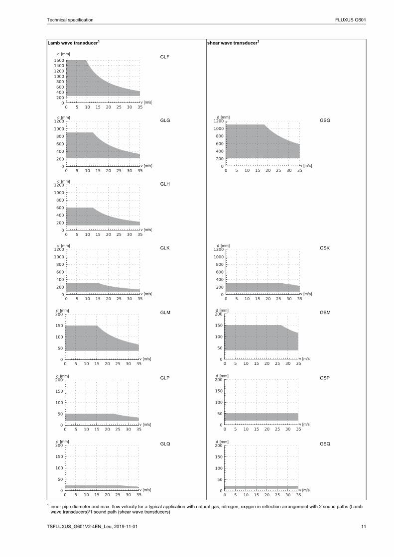
Lamb wave transducer1 shear wave transducer1
GLF
GLG GSG
GLH
GLK GSK
GLM GSM
GLP GSP
GLQ GSQ
1 inner pipe diameter and max. flow velocity for a typical application with natural gas, nitrogen, oxygen in reflection arrangement with 2 sound paths (Lamb wave transducers)/1 sound path (shear wave transducers)
FLUXUS G601 Technical specification
2019-11-01, TSFLUXUS_G601V2-4EN_Leu12
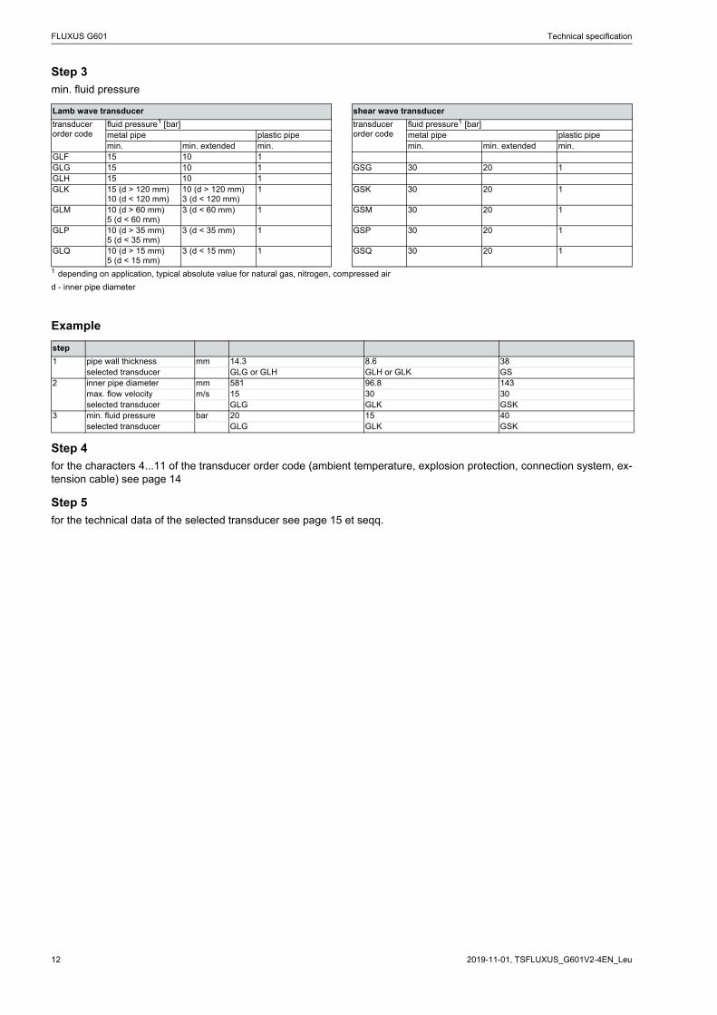
Step 3
min. fluid pressure
Example
Step 4
for the characters 4...11 of the transducer order code (ambient temperature, explosion protection, connection system, ex-tension cable) see page 14
Step 5
for the technical data of the selected transducer see page 15 et seqq.
Lamb wave transducer shear wave transducer
transducer order code
fluid pressure1 [bar] transducer order code
fluid pressure1 [bar]metal pipe plastic pipe metal pipe plastic pipemin. min. extended min. min. min. extended min.
GLF 15 10 1GLG 15 10 1 GSG 30 20 1GLH 15 10 1GLK 15 (d > 120 mm)
10 (d < 120 mm)10 (d > 120 mm)3 (d < 120 mm)
1 GSK 30 20 1
GLM 10 (d > 60 mm)5 (d < 60 mm)
3 (d < 60 mm) 1 GSM 30 20 1
GLP 10 (d > 35 mm)5 (d < 35 mm)
3 (d < 35 mm) 1 GSP 30 20 1
GLQ 10 (d > 15 mm)5 (d < 15 mm)
3 (d < 15 mm) 1 GSQ 30 20 1
1 depending on application, typical absolute value for natural gas, nitrogen, compressed air
d - inner pipe diameter
step
1 pipe wall thickness mm 14.3 8.6 38selected transducer GLG or GLH GLH or GLK GS
2 inner pipe diameter mm 581 96.8 143max. flow velocity m/s 15 30 30selected transducer GLG GLK GSK
3 min. fluid pressure bar 20 15 40selected transducer GLG GLK GSK
Technical specification FLUXUS G601
13TSFLUXUS_G601V2-4EN_Leu, 2019-11-01
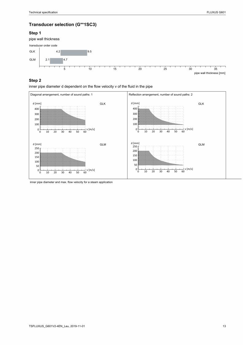
Transducer selection (G**1SC3)
Step 1
pipe wall thickness
Step 2
inner pipe diameter d dependent on the flow velocity v of the fluid in the pipe
transducer order code
GLK 4.2 9.5
GLM 2.1 4.7
5 10 15 20 25 30 35
pipe wall thickness [mm]
Diagonal arrangement, number of sound paths: 1 Reflection arrangement, number of sound paths: 2
GLK GLK
GLM GLM
inner pipe diameter and max. flow velocity for a steam application
00 10 20 30 40 50 60
100
200
300
400
d [mm]
v [m/s] 00 10 20 30 40 50 60
100
200
300
400
d [mm]
v [m/s]
00 10 20 30 40 50 60
50100
150200250
d [mm]
v [m/s] 00 10 20 30 40 50 60
50
100
150
200250
d [mm]
v [m/s]
FLUXUS G601 Technical specification
2019-11-01, TSFLUXUS_G601V2-4EN_Leu14
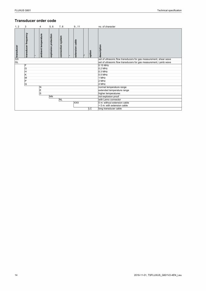
Transducer order code
1, 2 3 4 5, 6 7, 8 9...11 no. of character
tran
sdu
cer
tran
sdu
cer
fre
qu
en
cy
- amb
ien
t te
mp
era
ture
exp
losi
on
pro
tect
ion
con
ne
ctio
n s
ys
tem
- exte
nsi
on
ca
ble
/ op
tio
n
des
crip
tio
n
GS set of ultrasonic flow transducers for gas measurement, shear waveGL set of ultrasonic flow transducers for gas measurement, Lamb wave
F 0.15 MHzG 0.2 MHzH 0.3 MHzK 0.5 MHzM 1 MHzP 2 MHzQ 4 MHz
N normal temperature rangeE extended temperature rangeS higher temperatures
NN not explosion proofNL with Lemo connector
XXX 0 m: without extension cable> 0 m: with extension cable
LC long transducer cable
Technical specification FLUXUS G601
15TSFLUXUS_G601V2-4EN_Leu, 2019-11-01
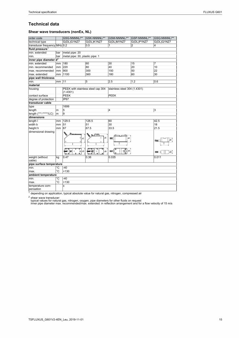
Technical data
Shear wave transducers (nonEx, NL)
order code GSG-NNNNL/** GSK-NNNNL/** GSM-NNNNL/** GSP-NNNNL/** GSQ-NNNNL/**technical type G(DL)G1NZ7 G(DL)K1NZ7 G(DL)M1NZ7 G(DL)P1NZ7 G(DL)Q1NZ7transducer frequency MHz 0.2 0.5 1 2 4fluid pressure1
min. extended bar metal pipe: 20min. bar metal pipe: 30, plastic pipe: 1inner pipe diameter d2
min. extended mm 180 60 30 15 7min. recommended mm 220 80 40 20 10max. recommended mm 900 300 150 50 22max. extended mm 1100 360 180 60 30pipe wall thicknessmin. mm 11 5 2.5 1.2 0.6materialhousing PEEK with stainless steel cap 304
(1.4301)stainless steel 304 (1.4301)
contact surface PEEK PEEKdegree of protection IP67transducer cabletype 1699length m 5 4 3length (***-*****/LC) m 9dimensionslength l mm 129.5 126.5 60 42.5width b mm 51 51 30 18height h mm 67 67.5 33.5 21.5dimensional drawing
weight (without cable)
kg 0.47 0.36 0.035 0.011
pipe surface temperaturemin. °C -40max. °C +130ambient temperaturemin. °C -40max. °C +130temperature com-pensation
x
1 depending on application, typical absolute value for natural gas, nitrogen, compressed air2 shear wave transducer:
typical values for natural gas, nitrogen, oxygen, pipe diameters for other fluids on requestinner pipe diameter max. recommended/max. extended: in reflection arrangement and for a flow velocity of 15 m/s
l
hb
l
hb
l
hb
l
hb
FLUXUS G601 Technical specification
2019-11-01, TSFLUXUS_G601V2-4EN_Leu16
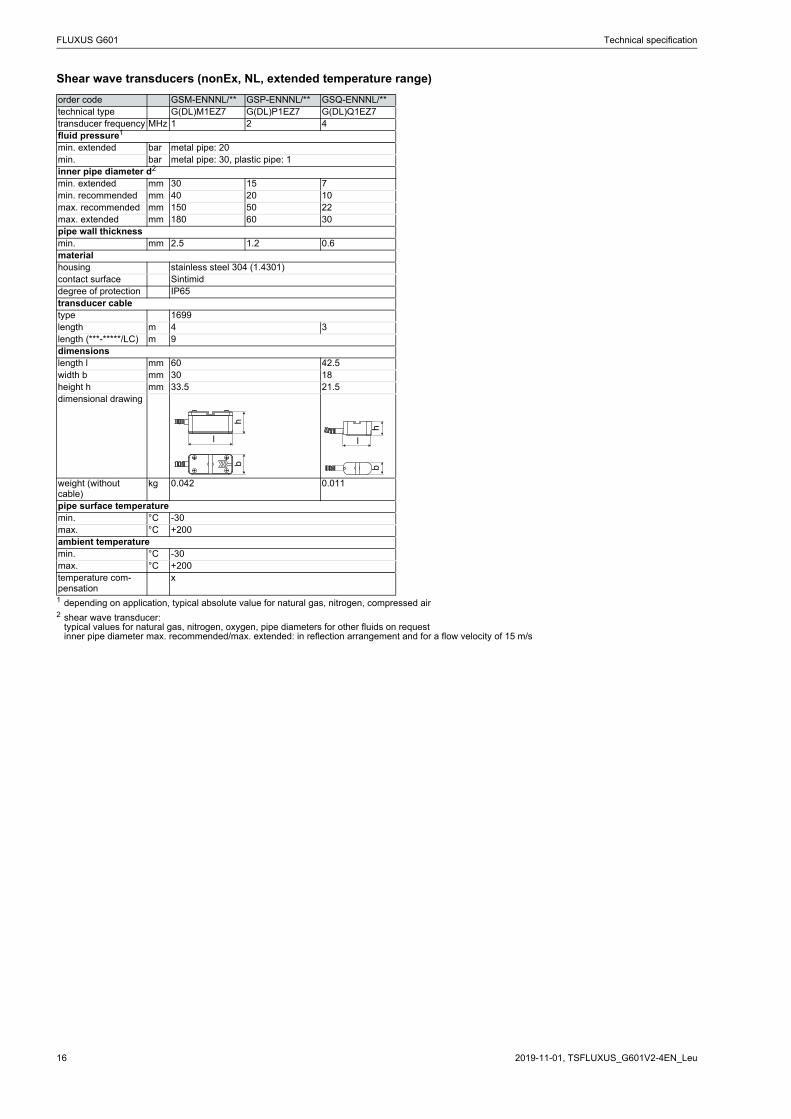
Shear wave transducers (nonEx, NL, extended temperature range)
order code GSM-ENNNL/** GSP-ENNNL/** GSQ-ENNNL/**technical type G(DL)M1EZ7 G(DL)P1EZ7 G(DL)Q1EZ7transducer frequency MHz 1 2 4fluid pressure1
min. extended bar metal pipe: 20min. bar metal pipe: 30, plastic pipe: 1inner pipe diameter d2
min. extended mm 30 15 7min. recommended mm 40 20 10max. recommended mm 150 50 22max. extended mm 180 60 30pipe wall thicknessmin. mm 2.5 1.2 0.6materialhousing stainless steel 304 (1.4301)contact surface Sintimiddegree of protection IP65transducer cabletype 1699length m 4 3length (***-*****/LC) m 9dimensionslength l mm 60 42.5width b mm 30 18height h mm 33.5 21.5dimensional drawing
weight (without cable)
kg 0.042 0.011
pipe surface temperaturemin. °C -30max. °C +200ambient temperaturemin. °C -30max. °C +200temperature com-pensation
x
1 depending on application, typical absolute value for natural gas, nitrogen, compressed air2 shear wave transducer:
typical values for natural gas, nitrogen, oxygen, pipe diameters for other fluids on requestinner pipe diameter max. recommended/max. extended: in reflection arrangement and for a flow velocity of 15 m/s
l
hb
l
hb
Technical specification FLUXUS G601
17TSFLUXUS_G601V2-4EN_Leu, 2019-11-01
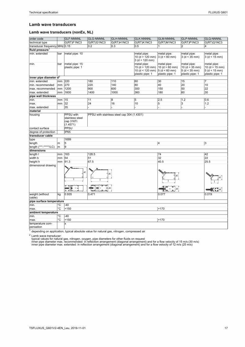
Lamb wave transducers
Lamb wave transducers (nonEx, NL)
order code GLF-NNNNL GLG-NNNNL GLH-NNNNL GLK-NNNNL GLM-NNNNL GLP-NNNNL GLQ-NNNNL technical type G(RT)F1NC3 G(RT)G1NC3 G(RT)H1NC3 G(RT)K1NC3 G(RT)M1NC3 G(RT)P1NC3 G(RT)Q1NC3transducer frequency MHz 0.15 0.2 0.3 0.5 1 2 4fluid pressure1
min. extended bar metal pipe: 10 metal pipe:10 (d > 120 mm)3 (d < 120 mm)
metal pipe:3 (d < 60 mm)
metal pipe:3 (d < 35 mm)
metal pipe:3 (d < 15 mm)
min. bar metal pipe: 15plastic pipe: 1
metal pipe:15 (d > 120 mm)10 (d < 120 mm)plastic pipe: 1
metal pipe:10 (d > 60 mm)5 (d < 60 mm)plastic pipe: 1
metal pipe:10 (d > 35 mm)5 (d < 35 mm)plastic pipe: 1
metal pipe:10 (d > 15 mm)5 (d < 15 mm)plastic pipe: 1
inner pipe diameter d2
min. extended mm 220 180 110 60 30 15 7min. recommended mm 270 220 140 80 40 20 10max. recommended mm 1200 900 600 300 150 50 22max. extended mm 1600 1400 1000 360 180 60 30pipe wall thicknessmin. mm 15 11 8 5 2.5 1.2 0.6max. mm 32 24 16 10 5 3 1.2max. extended 35 - - - - - -materialhousing PPSU with
stainless steel cap 316Ti (1.4571)
PPSU with stainless steel cap 304 (1.4301)
contact surface PPSUdegree of protection IP65transducer cabletype 1699length m 5 4 3length (***-*****/LC) m 9dimensionslength l mm 163 128.5 74 42width b mm 54 51 32 22height h mm 91.3 67.5 40.5 25.5dimensional drawing
weight (without cable)
kg 0.935 0.471 0.077 0.019
pipe surface temperaturemin. °C -40max. °C +150 +170ambient temperaturemin. °C -40max. °C +150 +170temperature com-pensation
x
1 depending on application, typical absolute value for natural gas, nitrogen, compressed air2 Lamb wave transducer:
typical values for natural gas, nitrogen, oxygen, pipe diameters for other fluids on requestinner pipe diameter max. recommended: in reflection arrangement (diagonal arrangement) and for a flow velocity of 15 m/s (30 m/s)inner pipe diameter max. extended: in reflection arrangement (diagonal arrangement) and for a flow velocity of 12 m/s (25 m/s)
l
h
l
hb
l
hb
l
hb
FLUXUS G601 Technical specification
2019-11-01, TSFLUXUS_G601V2-4EN_Leu18
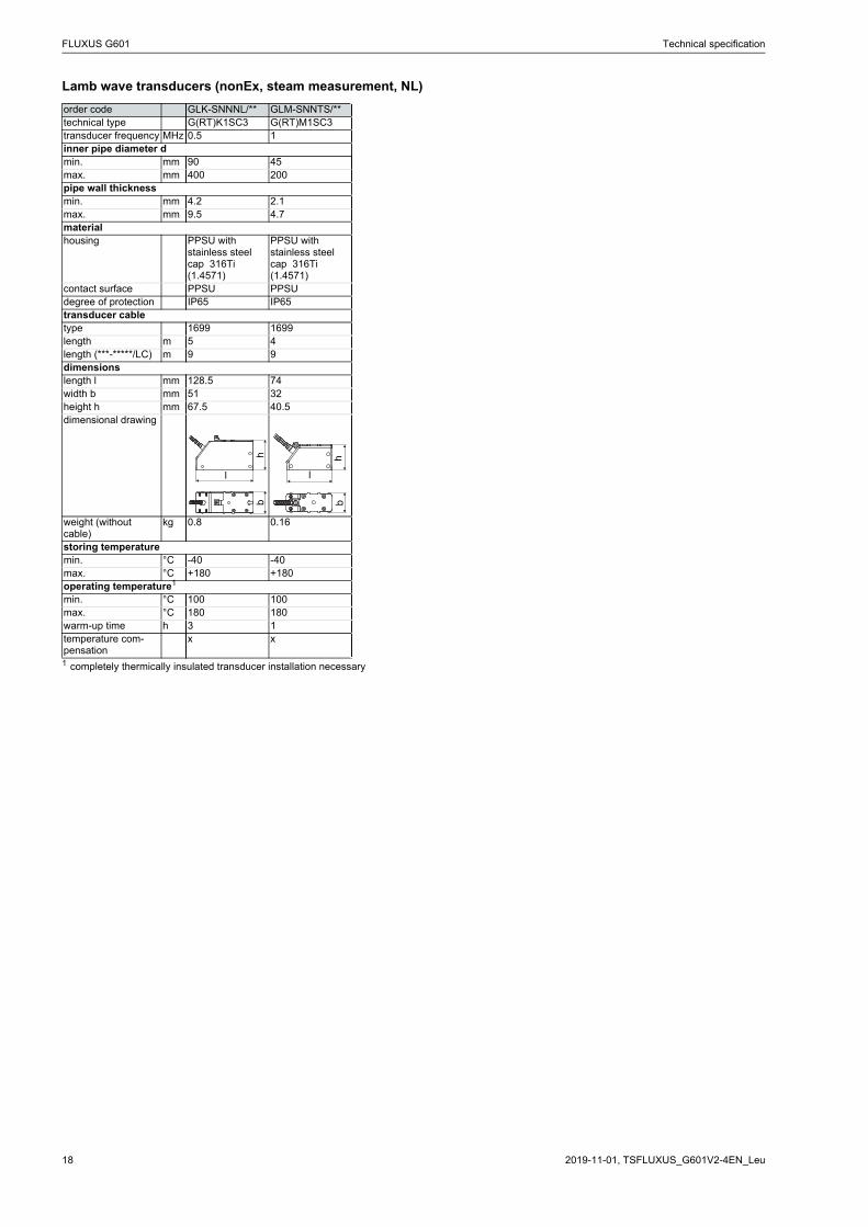
Lamb wave transducers (nonEx, steam measurement, NL)
order code GLK-SNNNL/** GLM-SNNTS/**technical type G(RT)K1SC3 G(RT)M1SC3transducer frequency MHz 0.5 1inner pipe diameter dmin. mm 90 45max. mm 400 200pipe wall thicknessmin. mm 4.2 2.1max. mm 9.5 4.7materialhousing PPSU with
stainless steel cap 316Ti (1.4571)
PPSU with stainless steel cap 316Ti (1.4571)
contact surface PPSU PPSUdegree of protection IP65 IP65transducer cabletype 1699 1699length m 5 4length (***-*****/LC) m 9 9dimensionslength l mm 128.5 74width b mm 51 32height h mm 67.5 40.5dimensional drawing
weight (without cable)
kg 0.8 0.16
storing temperaturemin. °C -40 -40max. °C +180 +180operating temperature1
min. °C 100 100max. °C 180 180warm-up time h 3 1temperature com-pensation
x x
1 completely thermically insulated transducer installation necessary
l
hb
l
hb
Technical specification FLUXUS G601
19TSFLUXUS_G601V2-4EN_Leu, 2019-11-01
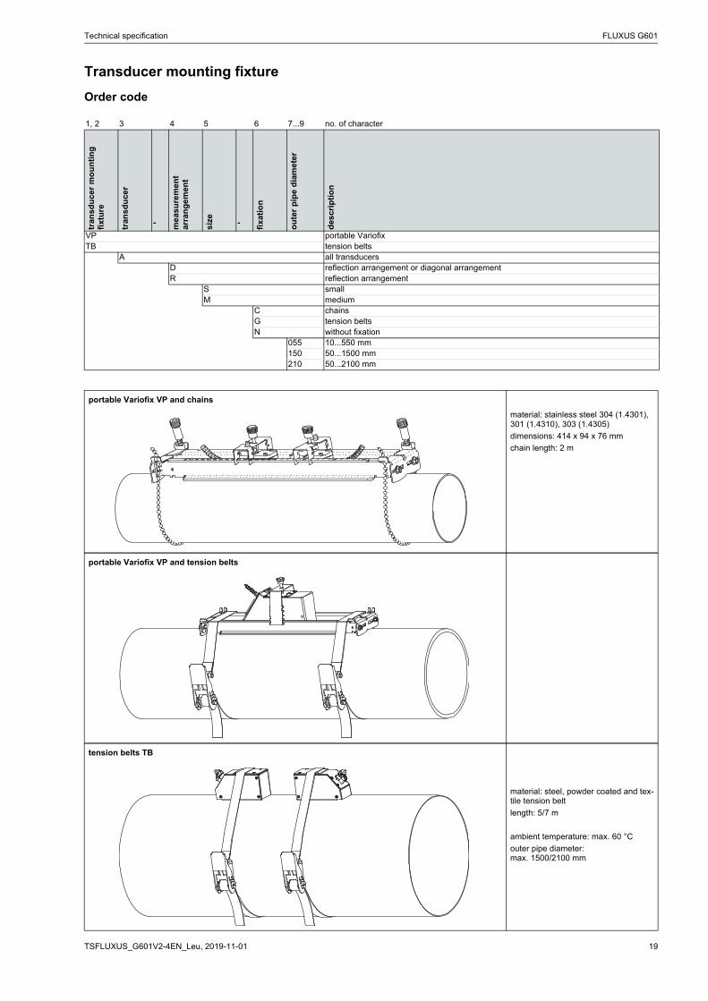
Transducer mounting fixture
Order code
1, 2 3 4 5 6 7...9 no. of character
tran
sdu
cer
mo
un
tin
g
fixt
ure
tran
sdu
cer
- me
asu
rem
en
t ar
ran
gem
ent
size - fixa
tio
n
ou
ter
pip
e d
iam
ete
r
des
crip
tio
n
VP portable VariofixTB tension belts
A all transducersD reflection arrangement or diagonal arrangementR reflection arrangement
S smallM medium
C chainsG tension beltsN without fixation
055 10...550 mm150 50...1500 mm210 50...2100 mm
portable Variofix VP and chains
material: stainless steel 304 (1.4301), 301 (1.4310), 303 (1.4305)
dimensions: 414 x 94 x 76 mm
chain length: 2 m
portable Variofix VP and tension belts
tension belts TB
material: steel, powder coated and tex-tile tension belt
length: 5/7 m
ambient temperature: max. 60 °C
outer pipe diameter:max. 1500/2100 mm
FLUXUS G601 Technical specification
2019-11-01, TSFLUXUS_G601V2-4EN_Leu20
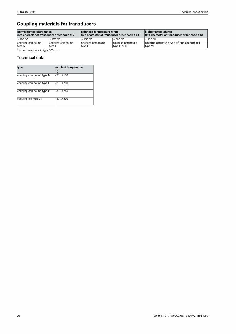
Coupling materials for transducers
Technical data
normal temperature range(4th character of transducer order code = N)
extended temperature range(4th character of transducer order code = E)
higher temperatures(4th character of transducer order code = S)
< 100 °C < 170 °C < 150 °C < 200 °C < 180 °Ccoupling compound type N
coupling compound type E
coupling compound type E
coupling compoundtype E or H
coupling compound type E1 and coupling foil type VT
2 in combination with type VT only
type ambient temperature
°Ccoupling compound type N -30...+130
coupling compound type E -30...+200
coupling compound type H -30...+250
coupling foil type VT -10...+200
Technical specification FLUXUS G601
21TSFLUXUS_G601V2-4EN_Leu, 2019-11-01
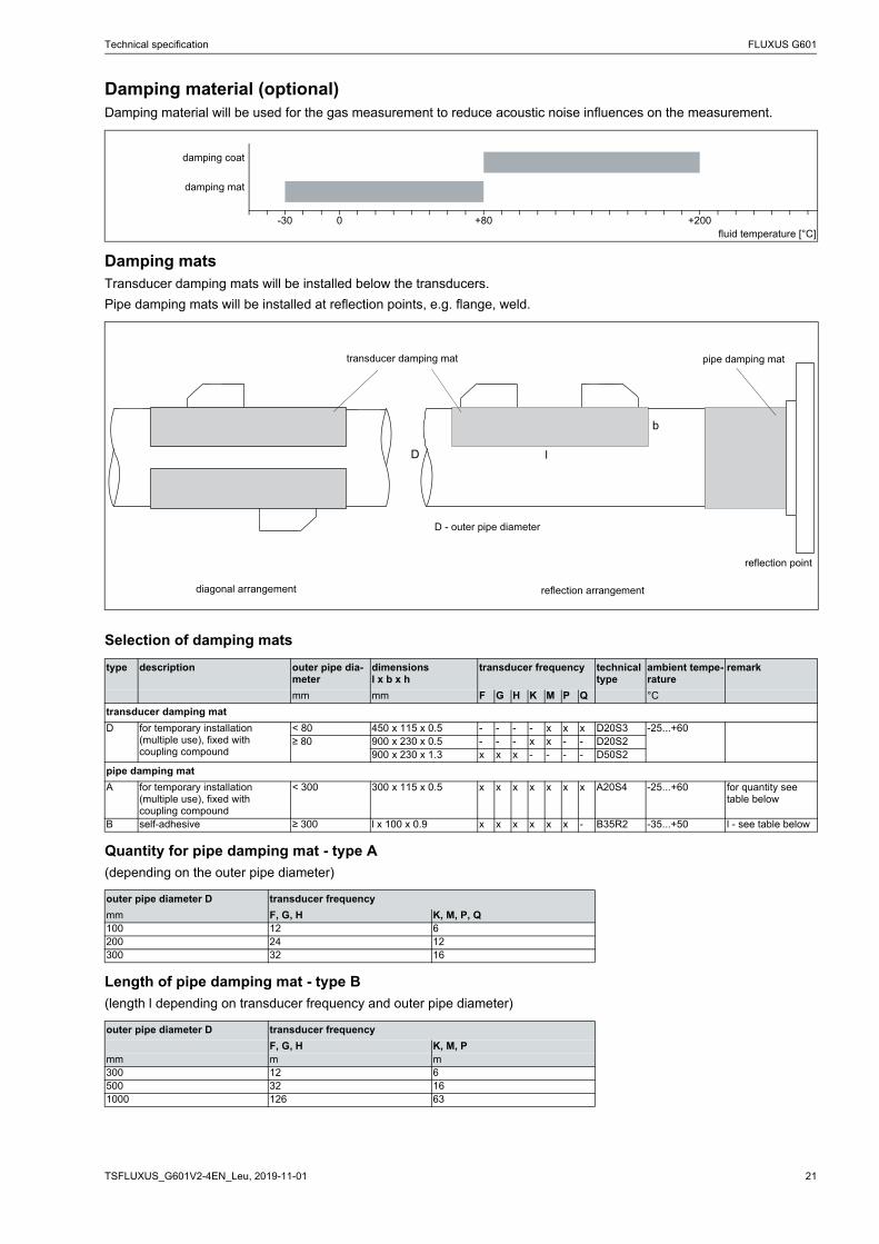
Damping material (optional)Damping material will be used for the gas measurement to reduce acoustic noise influences on the measurement.
Damping matsTransducer damping mats will be installed below the transducers.
Pipe damping mats will be installed at reflection points, e.g. flange, weld.
Selection of damping mats
Quantity for pipe damping mat - type A
(depending on the outer pipe diameter)
Length of pipe damping mat - type B
(length l depending on transducer frequency and outer pipe diameter)
damping coat
damping mat
-30 0 +80 +200fluid temperature [°C]
type description outer pipe dia-meter
dimensionsl x b x h
transducer frequency technical type
ambient tempe-rature
remark
mm mm F G H K M P Q °C
transducer damping mat
D for temporary installation (multiple use), fixed with coupling compound
< 80 450 x 115 x 0.5 - - - - x x x D20S3 -25...+60≥ 80 900 x 230 x 0.5 - - - x x - - D20S2
900 x 230 x 1.3 x x x - - - - D50S2
pipe damping mat
A for temporary installation (multiple use), fixed with coupling compound
< 300 300 x 115 x 0.5 x x x x x x x A20S4 -25...+60 for quantity see table below
B self-adhesive ≥ 300 l x 100 x 0.9 x x x x x x - B35R2 -35...+50 l - see table below
outer pipe diameter D transducer frequency
mm F, G, H K, M, P, Q100 12 6200 24 12300 32 16
outer pipe diameter D transducer frequency
F, G, H K, M, Pmm m m300 12 6500 32 161000 126 63
b
lD
transducer damping mat pipe damping mat
reflection arrangementdiagonal arrangement
D - outer pipe diameter
reflection point
FLUXUS G601 Technical specification
2019-11-01, TSFLUXUS_G601V2-4EN_Leu22
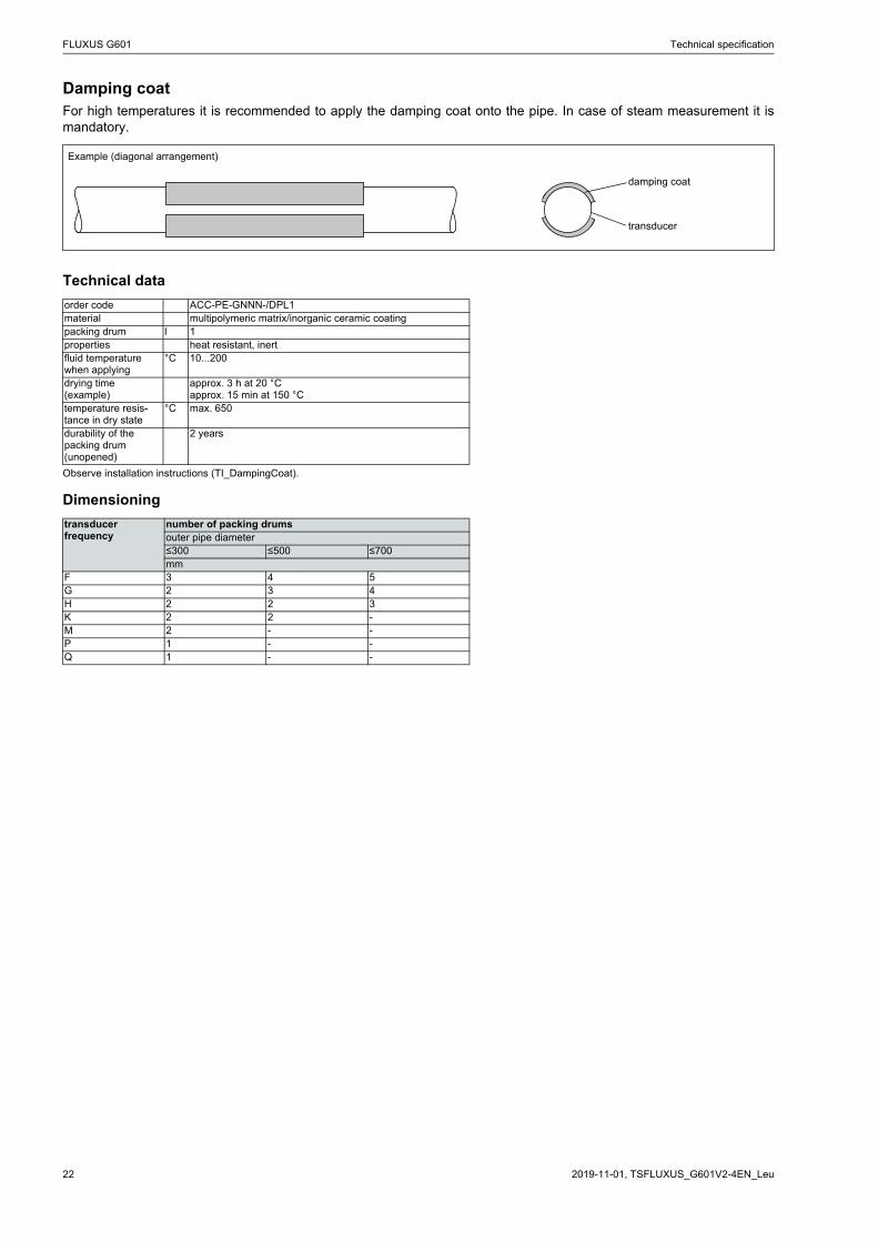
Damping coatFor high temperatures it is recommended to apply the damping coat onto the pipe. In case of steam measurement it ismandatory.
Technical data
Dimensioning
Example (diagonal arrangement)
order code ACC-PE-GNNN-/DPL1material multipolymeric matrix/inorganic ceramic coatingpacking drum l 1properties heat resistant, inertfluid temperature when applying
°C 10...200
drying time (example)
approx. 3 h at 20 °Capprox. 15 min at 150 °C
temperature resis-tance in dry state
°C max. 650
durability of the packing drum (unopened)
2 years
Observe installation instructions (TI_DampingCoat).
transducer frequency
number of packing drumsouter pipe diameter≤300 ≤500 ≤700mm
F 3 4 5G 2 3 4H 2 2 3K 2 2 -M 2 - -P 1 - -Q 1 - -
damping coat
transducer
Technical specification FLUXUS G601
23TSFLUXUS_G601V2-4EN_Leu, 2019-11-01
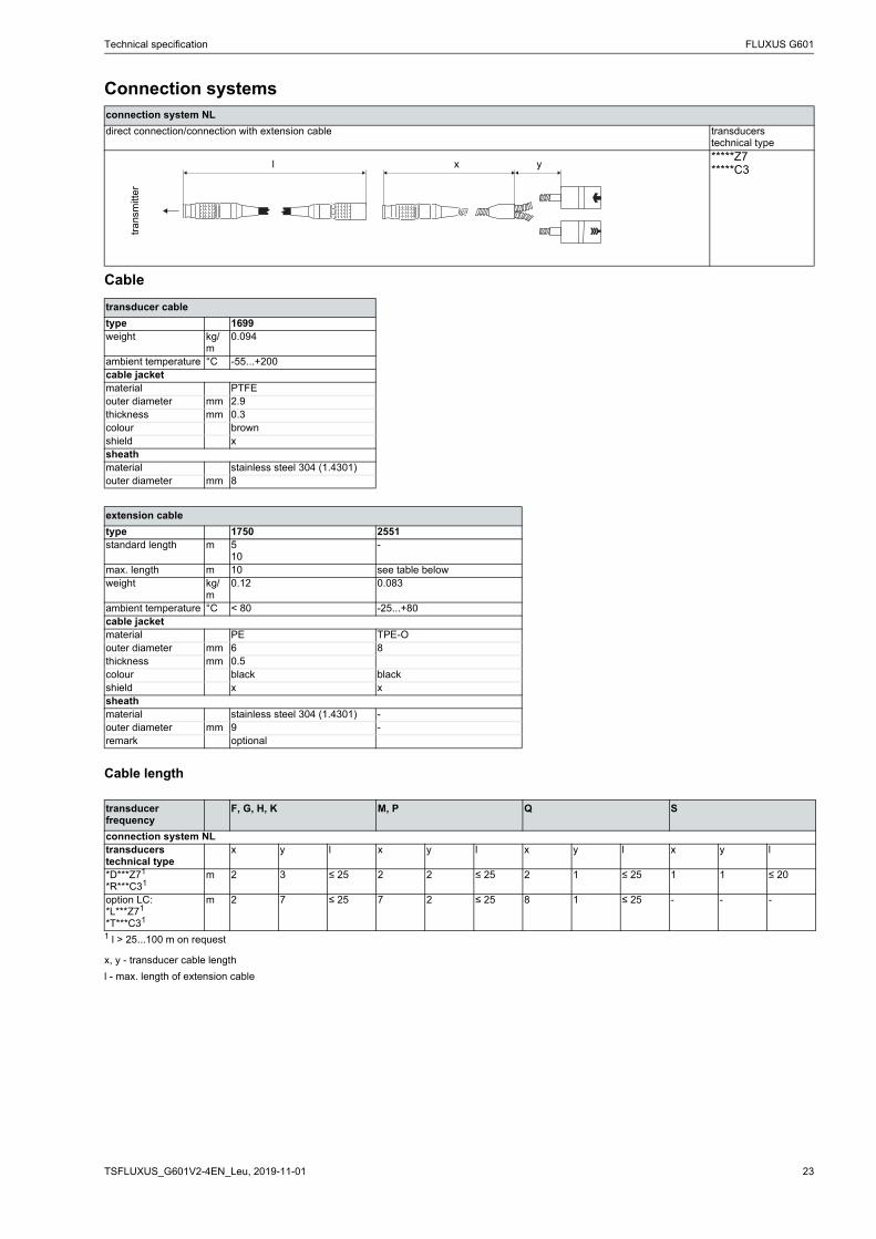
Connection systems
Cable
Cable length
connection system NL
direct connection/connection with extension cable transducerstechnical type*****Z7*****C3
transducer cable
type 1699weight kg/
m0.094
ambient temperature °C -55...+200cable jacketmaterial PTFEouter diameter mm 2.9thickness mm 0.3colour brownshield xsheathmaterial stainless steel 304 (1.4301)outer diameter mm 8
extension cable
type 1750 2551standard length m 5
10-
max. length m 10 see table belowweight kg/
m0.12 0.083
ambient temperature °C < 80 -25...+80cable jacketmaterial PE TPE-Oouter diameter mm 6 8thickness mm 0.5colour black blackshield x xsheathmaterial stainless steel 304 (1.4301) -outer diameter mm 9 -remark optional
transducer frequency
F, G, H, K M, P Q S
connection system NLtransducerstechnical type
x y l x y l x y l x y l
*D***Z71
*R***C31m 2 3 ≤ 25 2 2 ≤ 25 2 1 ≤ 25 1 1 ≤ 20
option LC:*L***Z71
*T***C31
m 2 7 ≤ 25 7 2 ≤ 25 8 1 ≤ 25 - - -
1 l > 25...100 m on request
x, y - transducer cable length
l - max. length of extension cable
tra
nsm
itte
r
l x y

FLUXUS G601 Technical specification
2019-11-01, TSFLUXUS_G601V2-4EN_Leu24
Clamp-on temperature probe (optional)
Technical data
PT12N
order code ACC-PO-#601-/T103
ACC-PO-#601-/T101 (matched)
design clamp-onwith connector
type Pt100connection 4-wiremeasuring range °C -30...+250accuracy T ±(0.15 °C + 2 . 10-3 . |T [°C]|)
class Aaccuracy ΔT(2x Pt matched according to EN 1434-1)
≤ 0.1 K (3 K < ΔT < 6 K), more corresponding to EN 1434-1
response time s 50housing aluminumdegree of protection IP66dimensionslength l mm 20width b mm 15height h mm 13dimensional drawing
weight kg 0.25 (without connector)accessoriesthermal conductivity paste 200 °C
x
thermal conductivity foil 250 °C
x
PT12F
order code ACC-PO-#601-/T104
ACC-PO-#601-/T102 (matched)
design clamp-onshort response time,with connector
type Pt100connection 4-wiremeasuring range °C -50...+250accuracy T ±(0.15 °C + 2 . 10-3 . |T [°C]|)
class Aaccuracy ΔT(2x Pt matched according to EN 1434-1)
≤ 0.1 K (3 K < ΔT < 6 K), more corresponding to EN 1434-1
response time s 8housing PEEK, stainless steel 304
(1.4301), copperdegree of protection IP66dimensionslength l mm 14width b mm 30height h mm 27dimensional drawing
weight kg 0.32 (without connector)accessoriesthermal conductivity paste 200 °C
x
thermal conductivity foil 250 °C
x
plastic protection plate, insulation foam
x
Connection system
Connection
Cable
direct connection/connection with extension cable
temperature probe extension cable connector
pin
red grey 2
red/blue red 6
white/blue blue 1
white white 7
temperature probe extension cable
type 4 x 0.25 mm² black LIYCY 8 x 0.14 mm² greystandard length m 3 5/10/25max. length m - 200cable jacket PTFE PVC
extension cable
h
lb
Connection system
Connection
Cable
direct connection/connection with extension cable
temperature probe extension cable connector
pin
red grey 2
red/blue red 6
white/blue blue 1
white white 7
temperature probe extension cable
type 4 x 0.25 mm² black LIYCY 8 x 0.14 mm² greystandard length m 3 5/10/25max. length m - 200cable jacket PTFE PVC
extension cable
h
bl

Technical specification FLUXUS G601
25TSFLUXUS_G601V2-4EN_Leu, 2019-11-01
Fixation
tension strap PT12N
material: stainless steel 301 (1.4310), 410 (1.4006)
thermal insulation necessary
ball chain PT12F
material: stainless steel 316L (1.4404)
length: 1 m
FLUXUS G601 Technical specification
2019-11-01, TSFLUXUS_G601V2-4EN_Leu26
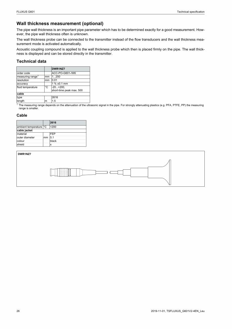
Wall thickness measurement (optional)The pipe wall thickness is an important pipe parameter which has to be determined exactly for a good measurement. How-ever, the pipe wall thickness often is unknown.
The wall thickness probe can be connected to the transmitter instead of the flow transducers and the wall thickness mea-surement mode is activated automatically.
Acoustic coupling compound is applied to the wall thickness probe which then is placed firmly on the pipe. The wall thick-ness is displayed and can be stored directly in the transmitter.
Technical data
Cable
DWR1NZ7
order code ACC-PO-G601-/W6measuring range1 mm 1...250resolution mm 0.01accuracy 1 % ±0.1 mmfluid temperature °C -20...+200,
short-time peak max. 500сabletype 2616length m 1.51 The measuring range depends on the attenuation of the ultrasonic signal in the pipe. For strongly attenuating plastics (e.g. PFA, PTFE, PP) the measuring
range is smaller.
2616
ambient temperature °C <200cable jacketmaterial FEPouter diameter mm 5.1colour blackshield x
DWR1NZ7

FLEXIM GmbHBoxberger Str. 4
12681 BerlinGermany
Tel.: +49 (30) 93 66 76 60Fax: +49 (30) 93 66 76 80
internet: www.flexim.come-mail: [email protected]
Subject to change without notification.Errors excepted.
FLUXUS is a registered trademark of FLEXIM GmbH.
Copyright (©) FLEXIM GmbH 2019
2019-11-01, TSFLUXUS_G601V2-4EN_Leu