technical specification for lt three phase ... 03/04sep’13 technical specification for lt three...
TRANSCRIPT

1
03/04Sep’13
TECHNICAL SPECIFICATION FOR LT THREE PHASE ELECTRONIC
WHOLE CURRENT TRIVECTOR ENERGY METERS (5-30A),CLASS 1.0
1.0 SCOPE :
1.1 This specification covers design, engineering, manufacture, assembly,
stage testing, inspection and testing before supply and delivery at destination stores of LT Three Phase, 4 wire 3 element, 5-30A Whole
Current Electronic Trivector Energy Meters of accuracy class 1.0 with backlit LCD as per requirement given in this specification in pilfer proof
box.
The above meters shall be supplied in a pilfer proof box which shall be weather proof made out of transparent Polycarbonate with flame
retardant properties. The meter and box should be supplied in suitable packing so as to withstand transit shocks.
1.2 It is not the intent to specify completely herein all the details of the
design and construction of material. However the material shall conform in all respects to high standards of engineering, design and
workmanship and shall be capable of performing in continuous commercial operation, in a manner acceptable to the purchaser, who
will interpret the meanings of drawings and specification and shall have the power to reject any work or material which, in his judgment
is not in accordance therewith. The offered material shall be complete with all components necessary for their effective and trouble free
operation. Such, components shall be deemed to be within the scope of Bidder's supply irrespective of whether those are specifically brought
out in this specification and/or the commercial order or not.
1.3 The original manufacturers of LT A.C. Static Three Phase energy meters shall only quote against this tender. In case of foreign
manufactures their authorized agent may also bid provided that they should be registered vendor and shall have all the testing facilities in
India. They should also produce the documents authorizing them as agents, in India.
1.4 It is mandatory that in case of all manufacturers, the offered meter
shall be ISI marked and bidder shall have to furnish valid BIS certificate along with the offer.
2.0. STANDARDS:
2.1 Unless specified elsewhere in this specification, the performance & testing of the meters should conform to the following Indian /
International standards, to be read with up to-date and latest amendments / revisions thereof as on 90 days prior to floating of
tender.
(1) Indian Standard No. IS 13779 of 1999 with latest amendments -
AC Static Watt hour Meters, Class 1 – Specification.

2
(2) IEC 61358:1996-Acceptance inspection for direct connected
meters.
(3) IEC 62052&53-Particular requirements for direct connected
meters.
(4) IEC 61000-4-5:2001-04-immunity tests.
(5) IS.14697 of 1999 – Clause 1.3.(for APF)
(6) IS.12063 – Degree of protection for enclosures.
(7) IS.12346 –Testing equipments.
(8) IEC 62053-11, 21&61-test, requirement & power consumption.
(9) IEC-61000-4, 5 & 6- EMI/EMC Withstand
(10) IS 11000- Fire hazard testing
(11) IS-9000 – BET procedures.
(12) IEC.15707, 2006- Testing & maintenance of AC meters, code of
practice.
(14) CBIP-304/July 2008-Standardization of AC Static Electrical Energy Meters.
(15) CEA installation and operation of meters regulations with all amendments.
2.2 CONFLICT OF STANDARDS :
Material conforming to other internationally accepted standards, which
ensure equal or higher quality than the standards mentioned above would also be acceptable. In case the Bidders who wish to offer
material conforming to the other standards, salient points of difference between the standards adopted and the specific standards shall be
clearly brought out in relevant schedule. Two copies of such standards with authentic English Translations, shall be furnished along with the
offer. In case of conflict the order of precedence shall be (i) IS (ii) CBIP 304 and (iii) other standards. In case of any difference between
provisions of these standards and provisions of the specification, the provisions contained in specification shall prevail.
3.0 CLIMATIC CONDITIONS :
The materials to be supplied against this specification shall be suitable for satisfactory continuous operation under the following tropical
conditions.
Location
At various locations in the state of Andhra
Pradesh
Max. ambient air temperature (deg.C) 50
Max. ambient air temperature in a closed box (deg.C) 60
Min. ambient air temperature (deg.C) 7.5
Average daily ambient air temp. (deg.C) 35
Max. Relative Humidity (%) 100
Max. altitude above mean sea level (m) 1000
Average Annual rainfall(mm) 925
Max. wind pressure(kg/sq. m.) 200

3
Isoceraunic level(days per year) 50
Seismic level(Horizontal acceleration) 0.3 g.
Permitted Noise Level 45 dB
Moderately hot and humid tropical climate is conducive to rust and fungus growth. The climatic conditions are also prone to wide
variations in the ambient conditions, Smoke is also present in the atmosphere, Heavy lightning also occurs during June to October.
4.0. PRINCIPAL PARAMETERS : The equipment shall conform to the following specific parameters:
Sl. No.
Item Specification
1. Type of Installation Indoor
2. System voltage 3x240V +20%, -40% Phase to neutral
3. System frequency 50 Hz +/- 5%
4. No. of phases Three Phase 4wire
5. System of earthing Solidly grounded
6. Current 0.2% of Imin of 5-30A to 150% of I max
for 5-30A
7. Power factor range Zero lag – Unity – Zero lead
8. Resistance to impulse voltage Minimum 10KV peak as per IS test procedure.
9. Resistance to surge voltage Minimum 8KV peak of 1.2/50 Micro sec.
10. Test Voltage at 50 Hz for 1min
4 KV rms – as per IS 13779
11. Clock time accuracy +/- 7 min/year – as per CBIP - 304
4.1. The limits of error for +20 to -40% Vref variations shall be as under:-
(a) @ UPF 0.7% for Ib, (b) @ 0.5 lag 1.0% for Ib, (c) @ UPF 0.6% for
0.6 Ib & Imax with 10% 0f 3rd harmonic current in circuit.
5.0. TECHNICAL REQUIREMENTS:
5.1.2 Ratings :
1. Three phase meters as specified at clause 1.0 shall be rated as follows:
a) Voltage 3 x 240V (Phase to
neutral)
b) Current
i) Basic current (Ib) 5A
ii) Rated Max. Current (Imax) 30A
c) Frequency 50 Hz
d) Accuracy Class 1.0

4
5.1.3 Power Supply Variation:
The extreme power supply variation which the meter should withstand
without damage and without degradation of its metrological characteristics when it is subsequently operated under its normal
operating conditions:
Voltage -40% to +20%
Frequency +/- 5%
PF.range Zero lag-unity-zero lead (*)
(*) The meter shall work over wide PF range and the limits of errors
with the variation of PF shall be as per IS 13779 (latest version).
However manufacturer can offer meters which can withstand higher variations of voltage and frequency.
Note : The meter shall remain powered up and functional even in the event of only one phase is available.
The meter shall be able to continuously withstand phase to
phase voltage of 500V
Name Plate marking : The name plate drawing shall be got approved from the purchaser before commencement of manufacture.
5.1.4 Accuracy: Class of accuracy of meter shall be 1.0. The accuracy
should not drift with time. The reactive accuracy class of the meter shall be same as the active accuracy class. The internal least count of
energy recording shall not be more than 0.01 KWH/KVAH hence every 0.01 Kwh/Kvah consumption will be internally stored. Also there shall
be no loss of energy registration on account of power outages due to high start up time of the meter. To verify, the above the meter will be
switched off/on 40 times at rated parameters and energy recording on display with decimal digit should be within 0.4 Kwh/Kvah of the
energy, it should register, as per its accuracy at that load. This will be verified during testing sample meters and at works during inspection.
The meter reading should not be disturbed during sudden switching of heavy loads or transient voltage spikes.
5.1.5 CTs/SHUNT ARRANGEMENT
The meter shall operate on CT or shunt. The current circuit shall be appropriately insulated and designed to withstand the temperature
rise of 50˚C over the ambient at maximum current. Specific confirmation to be submitted by the vendor that the accuracy of
measurement will not suffer due to utilization of shunt on account of thermal variation and temperature coefficient up to an operational
temperature of 80˚C and shall comply with IS:13379(cl.9.4).The CTs shall have proper magnetic shield and shall be mounted firmly without
any movement. The bidders shall submit the details of the shunt and how they are protected against external influences & temperature
variations.

5
5.2 Power consumption:
5.2.1 Voltage circuit: The active and apparent power consumption in each voltage circuit including power supply of meter at reference
voltage, reference temperature and reference frequency shall not exceed 1 Watt and 4 VA per phase respectively.
5.2.2 Current circuit: The apparent power taken by each current circuit
at basic current, reference frequency and reference temperature shall not exceed 1VA.
The above losses are maximum allowable and there would not be any
positive tolerance.
5.2.3 Starting current: The meter should start registering energy at 0.2% of basic current.
5.2.4 Running with no load: When the voltage of 120% of rated voltage is
applied with no current flowing in the circuit, the test output of the meter shall not produce more than one pulse/count. The minimum
time test limit shall be as per IS 13779/1999.
5.3. Influence quantity: As per CBIP -304 .
5.4. Super capacitor
The meter shall have a super capacitor with sufficient capacity to
enable the meter reader to take reading under power off condition with
following provisions:
Suitable rechargeable super capacitor back up for continuous display
for 48 hours from instant of power failure. The display should be powered up
through push button only when power failure occurs. This arrangement shall
be robust such that down loading of meter data during power off condition is
not affected and minimum three down loads are guaranteed for a outage.
There shall be a suitable backup provision for display in case of super
capacitor failure. The performance of the super capacitor shall be verified
by removing all the batteries from the circuit in any meter during
sample testing or inspection. The charging time of super capacitor
shall not be more than 6 hours.
In any case, RTC battery power shall not be used for display under
power off condition. Battery used for the meter display during power off
condition shall be separate from the battery used for the real time clock.

6
5.4.1 Real time clock and battery:
The MD integration cycle shall be on the function of RTC of the meter.
The maximum drift in real time clock of the meter shall not exceed
plus or minus 7 minutes per year as per CBIP 304 and crystal should
be temperature compensated for temperature range of 0 to 50˚C when
powered by internal battery or supply. This shall be verified during
sample testing and inspection. A non-chargeable lithium battery of
adequate storage energy with 10 year guarantee period only should be
provided. Necessary document to this effect has to be submitted along
with the tender. If the battery fails within meter warranty period the
meter should be replaced by the supplier within 15 days from the date
of intimation failing which the entire cost of the meter will be recovered
from the balance payment due to the supplier.
The Synchronization of Meter RTC Time/day shall be possible through
password / key code enabled command from the Remote Server. In
case of meter connected to AMR system through GSM/GPRS/PLCC
modem, the meter should be able to synchronize its clock with the
system time. Super capacitor used for the meter display during power
off condition shall be separate from the battery used for the real time
clock.
Facility for correcting the drift in Real Time clock through CMRI has to
be provided with proper security. Whenever RTC is corrected, all the
registers and other parameters shall be updated. The date and time
should be user programmable. The meter should be capable of storing
in the memory the readings of a specified date and time in a month /
two months for the purpose of retrieving the same at a later date
without change in the specified timing while correcting the drift.
The data stored in the memory shall not be lost or updated when the
meter is in power off condition, so that same are retrievable even after
lapse of several months. (This is to enable utility to defend their cases
legally in case of disputed meters/billing revision.)
5.4.2 Non volatile Memory:
The meter should have non volatile memory, so that the registered
parameters will not be affected by loss of power. The non volatile memory
should have a minimum retention time of 10 years. It is the responsibility of
the meter manufacturer to retrieve the data from this memory, in the event of
display failure and other defects except for completely burnt meter as and
when requested by the purchaser with in a period of 30 days from the date of
intimation. The transportation cost for the same should be borne by the
7
supplier. If the data could not be retrieved for any reasons the same shall be
communicated to the respective circle M&P/MRT with the reason for non
retrieval.
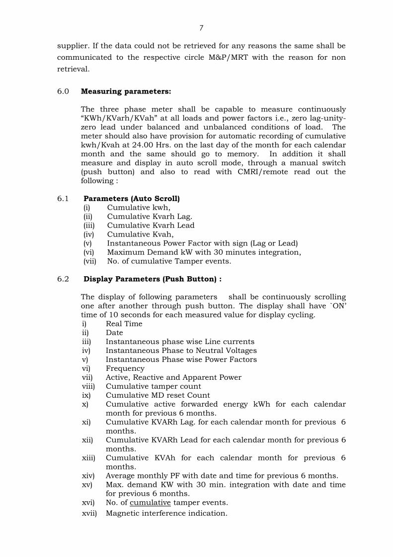
6.0 Measuring parameters:
The three phase meter shall be capable to measure continuously “KWh/KVarh/KVah” at all loads and power factors i.e., zero lag-unity-
zero lead under balanced and unbalanced conditions of load. The meter should also have provision for automatic recording of cumulative
kwh/Kvah at 24.00 Hrs. on the last day of the month for each calendar month and the same should go to memory. In addition it shall
measure and display in auto scroll mode, through a manual switch (push button) and also to read with CMRI/remote read out the
following :
6.1 Parameters (Auto Scroll) (i) Cumulative kwh,
(ii) Cumulative Kvarh Lag. (iii) Cumulative Kvarh Lead
(iv) Cumulative Kvah, (v) Instantaneous Power Factor with sign (Lag or Lead)
(vi) Maximum Demand kW with 30 minutes integration, (vii) No. of cumulative Tamper events.
6.2 Display Parameters (Push Button) :
The display of following parameters shall be continuously scrolling
one after another through push button. The display shall have `ON‟ time of 10 seconds for each measured value for display cycling.
i) Real Time ii) Date
iii) Instantaneous phase wise Line currents iv) Instantaneous Phase to Neutral Voltages
v) Instantaneous Phase wise Power Factors vi) Frequency
vii) Active, Reactive and Apparent Power viii) Cumulative tamper count
ix) Cumulative MD reset Count x) Cumulative active forwarded energy kWh for each calendar
month for previous 6 months. xi) Cumulative KVARh Lag. for each calendar month for previous 6
months. xii) Cumulative KVARh Lead for each calendar month for previous 6
months. xiii) Cumulative KVAh for each calendar month for previous 6
months. xiv) Average monthly PF with date and time for previous 6 months.
xv) Max. demand KW with 30 min. integration with date and time for previous 6 months.
xvi) No. of cumulative tamper events.
xvii) Magnetic interference indication.

8
xviii) Self Diagnostics (LCD Segment check & Battery check).
xix) For calibration purpose, High resolution reading for testing (Kwh, Kvarh Lag, Kvarh Lead, Kvah) should be displayed with a
minimum of four decimal digits.
6.3. Readout Parameters with CMRI/RMR/IRDA. :
i) Meter serial number, Model, Make. ii) All parameters at Clause 5.1.10.2. (Above).
iii) Load Survey data. iv) Tamper details of at least 70 events (in and out) with date and time
(i.e., 140 records). v) Self diagnostic details (Real time calendar, low battery).
Note :Meter shall continuously monitor and calculate the average
maximum demand for each demand interval time of 30 minutes and maximum of these in a calendar month shall be stored
along with date and time when it occurred. Whenever MD is reset, the maximum MD value so registered shall be stored
along with date and time.
Meter should be suitable for lag only tariff, blocking the leading PF, satisfying the
formula KVAH2 = KWH
2 + RKVAH
2 for lagging loads, KVAH = KWH for
leading loads.
The meter should measure the total energy consisting of 50 Hz energy and
harmonic energy both for active as well for reactive. Provision for displaying the
THD in % for voltage and current in each phase (Minimum up to 21st order) shall be
made available in the push button mode.
The Average power factor for the billing period may be calculated as
per IS.14697 of 1999 – Clause 1.3.and G-7.
6.4 In addition to providing on the Name plate, the meter serial number
shall also be programmed into meter memory for identification through CMRI/remote reading and meter reading print out.
The bidder shall indicate any additional measurement and display
features being offered in addition to the above minimum requirement.
6.5 MD Reset : The meter should have provision of maximum demand
resetting : (i) Manual resetting (ii) Resetting shall be possible through a
handheld Common Meter Reading Instrument (CMRI) capable of
communicating with the meter with the help of Lap Top. (iii) Auto reset
at 24.00 Hrs of the last date of each calendar month for which
minimum 30 years calendar shall be programmed by the
manufacturer. The cumulative KWh&Kvah should also be recorded at
24.00 Hrs. on the last date of each calendar month for previous six
months. DIP shall be set at 30 minutes duration. DIP shall
commence at the fixed time intervals of real time.
MD recording of Block method is to be used. Necessary software is to
be provided for changing DIP to 15minutes.

9
The rising value of current demand with rising time should be
held in the memory in the event of interruption (or) switching off power
supply and it should not fall to zero on such instances.
7.0 LCD Display:
The meters shall have bright LCD Electronic display with backlit and with minimum (6+1) digits. The backlit should not glow during power off condition. The LCD shall be industrial grade with multi layer & of
STN (Super Twisted Nematic) type construction suitable for temperature withstand of 80°c (storage) & 65°c (operation) i.e.,
a. When the meter is placed over at a constant temperature of 65°c for
a period of 30 minutes, the character of LCD should not deform.
b. After keeping the meter at a constant temperature of 80°c for a period of 30minutes and when restores at normal temperature,
LCD display shall work satisfactorily.
Note: The LCD should be hard pin type and soldered to PCB.
The LCD display should have a wide viewing angle of 120° and up to one meter distance, for clear visibility of the display of the meter
reading at distance with backlight in green and characters/digits in black. Large viewing area with large display icons is preferred.
However, the display size area should not be less than 55 x 14 mm. The registered parameters shall not be affected by loss of power. The
display shall not be affected by electrical and magnetic disturbances. The data should be stored in non-volatile memory. The non-volatile
memory should retain data for a period of not less than 10 years under unpowered condition. Battery back-up memory will not be considered
as NVM.
The register shall be able to record and display starting from zero, for a minimum of 2500 hours. The energy corresponding to
rated maximum current at reference voltage and unity power factor. The register should not roll over in between this duration. In addition
to provide Serial Number of the meter on the display plate, the meter serial should also be programmed into meter memory for identification
through communication port for CMRI / laptop / meter reading printout.
The minimum character height x width shall be 10x5mm. Dot
matrix type LCD display is not acceptable.
All important data such as calibration data, billing parameters and cumulative KWh/KVAh should be stored in Non-Volatile Memory
(NVM) internal to the main processing circuit and it should not be possible to change the data through any standard serial
communication.
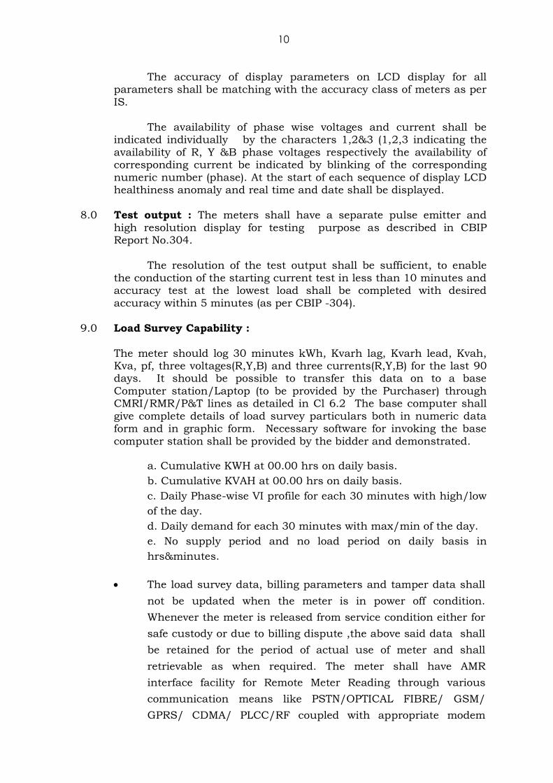
10
The accuracy of display parameters on LCD display for all parameters shall be matching with the accuracy class of meters as per
IS.
The availability of phase wise voltages and current shall be indicated individually by the characters 1,2&3 (1,2,3 indicating the
availability of R, Y &B phase voltages respectively the availability of corresponding current be indicated by blinking of the corresponding
numeric number (phase). At the start of each sequence of display LCD healthiness anomaly and real time and date shall be displayed.
8.0 Test output : The meters shall have a separate pulse emitter and
high resolution display for testing purpose as described in CBIP Report No.304.
The resolution of the test output shall be sufficient, to enable
the conduction of the starting current test in less than 10 minutes and accuracy test at the lowest load shall be completed with desired
accuracy within 5 minutes (as per CBIP -304).
9.0 Load Survey Capability :
The meter should log 30 minutes kWh, Kvarh lag, Kvarh lead, Kvah, Kva, pf, three voltages(R,Y,B) and three currents(R,Y,B) for the last 90 days. It should be possible to transfer this data on to a base
Computer station/Laptop (to be provided by the Purchaser) through CMRI/RMR/P&T lines as detailed in Cl 6.2 The base computer shall
give complete details of load survey particulars both in numeric data form and in graphic form. Necessary software for invoking the base
computer station shall be provided by the bidder and demonstrated.
a. Cumulative KWH at 00.00 hrs on daily basis.
b. Cumulative KVAH at 00.00 hrs on daily basis.
c. Daily Phase-wise VI profile for each 30 minutes with high/low
of the day.
d. Daily demand for each 30 minutes with max/min of the day.
e. No supply period and no load period on daily basis in
hrs&minutes.
The load survey data, billing parameters and tamper data shall
not be updated when the meter is in power off condition.
Whenever the meter is released from service condition either for
safe custody or due to billing dispute ,the above said data shall
be retained for the period of actual use of meter and shall
retrievable as when required. The meter shall have AMR
interface facility for Remote Meter Reading through various
communication means like PSTN/OPTICAL FIBRE/ GSM/
GPRS/ CDMA/ PLCC/RF coupled with appropriate modem

11
based on communication backbone chosen. The
communication port shall also have a separate sealing
provision.
In the load survey graph, no supply period, no load period is to
be distinguished with cumulative values for each day for the above events.
The RS-232 port provided in the Meter shall be accessible using a USB
to Serial converter in case if PC/Laptop communicating to Meter is
having only USB Ports instead of RS-232 Ports. The Meter
Manufacturer shall also provide one no. compatible USB to RS-232
converter for each lot of 500 nos. Meters. This is the requirement
because USB is defacto standard of Industry.
It shall be responsibility of the meter manufacturer to provide
required software and all the facilities free of cost to enable the
use of IRDA as well as RS232 port for reading and retrieving the
data from the meter through CMRI and AMR and to download
the data to PC Necessary upgrades of software shall be supplied
free of cost for downloading simultaneously the existing
parameters and any parameters added in future specifications of
meters.
10.0 Communication capability :
10.1 The meter should have a properly secured IRDA port in front of the
meter for data transfer without error by CMRI/ISBM/HHM and
protocol as specified by the utility.
10.2 The meter shall also be provided with a RS-232 communication port in
front of the meter for data transfer or subsequently hooked to remote
metering device i.e. to enable for future adoption to any mode of
technology for Remote Meter Reading through various
communication means like PSTN/GSM/ GPRS/ CDMA/ PLCC/RF
coupled with appropriate modem based on communication backbone
chosen. The communication port shall also have a separate sealing
provision if the same was not provided inside the terminal cover. It
has to be designed as read and write, and locking should be provided
for writing mode.
12
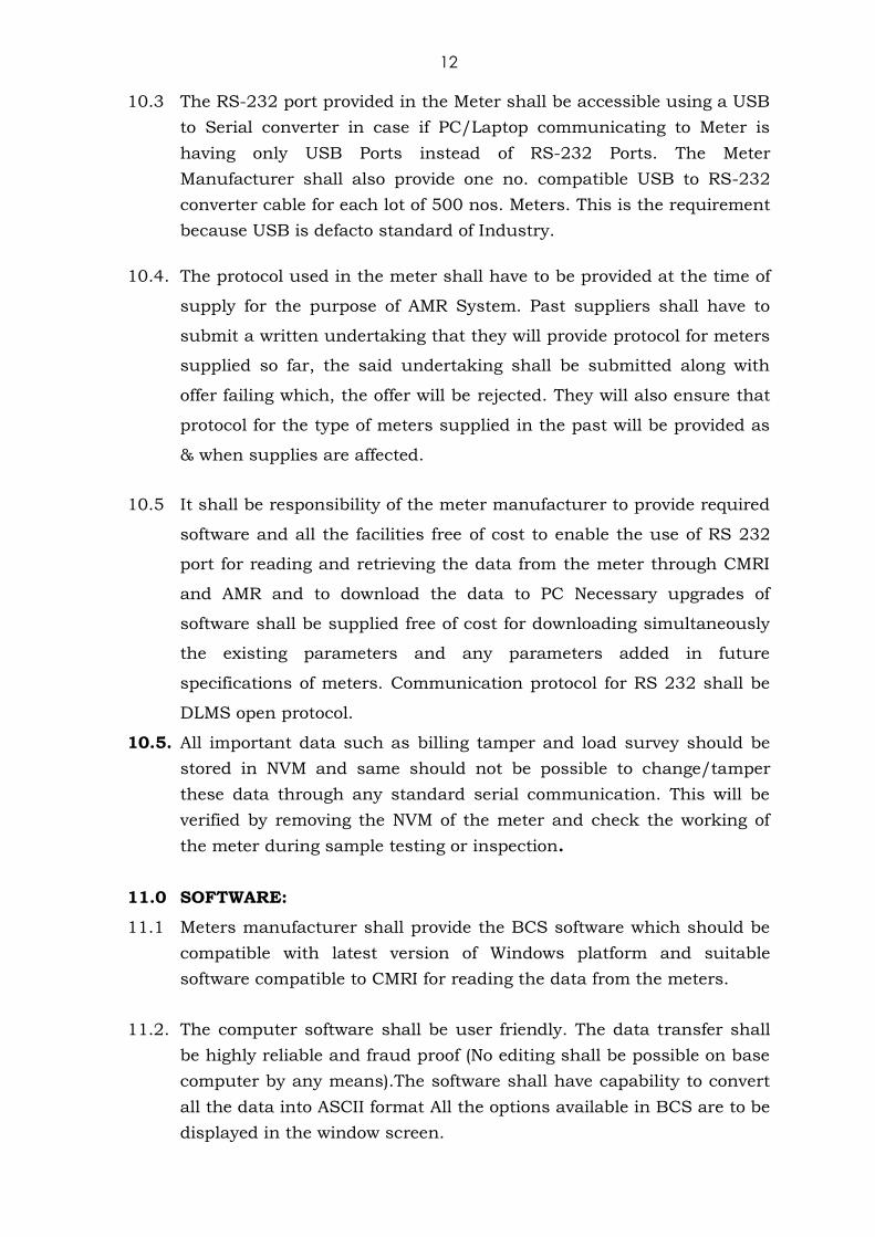
10.3 The RS-232 port provided in the Meter shall be accessible using a USB
to Serial converter in case if PC/Laptop communicating to Meter is
having only USB Ports instead of RS-232 Ports. The Meter
Manufacturer shall also provide one no. compatible USB to RS-232
converter cable for each lot of 500 nos. Meters. This is the requirement
because USB is defacto standard of Industry.
10.4. The protocol used in the meter shall have to be provided at the time of
supply for the purpose of AMR System. Past suppliers shall have to
submit a written undertaking that they will provide protocol for meters
supplied so far, the said undertaking shall be submitted along with
offer failing which, the offer will be rejected. They will also ensure that
protocol for the type of meters supplied in the past will be provided as
& when supplies are affected.
10.5 It shall be responsibility of the meter manufacturer to provide required
software and all the facilities free of cost to enable the use of RS 232
port for reading and retrieving the data from the meter through CMRI
and AMR and to download the data to PC Necessary upgrades of
software shall be supplied free of cost for downloading simultaneously
the existing parameters and any parameters added in future
specifications of meters. Communication protocol for RS 232 shall be
DLMS open protocol.
10.5. All important data such as billing tamper and load survey should be
stored in NVM and same should not be possible to change/tamper
these data through any standard serial communication. This will be
verified by removing the NVM of the meter and check the working of
the meter during sample testing or inspection.
11.0 SOFTWARE:
11.1 Meters manufacturer shall provide the BCS software which should be
compatible with latest version of Windows platform and suitable
software compatible to CMRI for reading the data from the meters.
11.2. The computer software shall be user friendly. The data transfer shall
be highly reliable and fraud proof (No editing shall be possible on base
computer by any means).The software shall have capability to convert
all the data into ASCII format All the options available in BCS are to be
displayed in the window screen.

13
11.3 The software to be installed in the CMRI/PC for the purpose of reading
and programming the specific make(s) of static meters shall be made
available by each meter manufacturer whose meters are to interface
with CMRI/PC.
11.4. The Software should have polling feature with optional selection of
parameters to be downloaded for AMR applications. The Software
should have programmable facility to restrict the access to the
information recorded at different security levels.
11.5. If the software supplied is of latest version than the earlier one
supplied, then the same shall be such that it is compatible for the
meters already supplied and also the meter data already read and
available at BCS to the extent possible. Confirmation to this effect
shall be furnished along with the offer.
12.0. The CMRI software should have the following provisions
a. Collection of data (All Data including dumped)
b. Download to BCS using same menu in BCS and CMRI
c. Billing
d. Load Survey
e. Tamper
f. Setting
g. Name plate (Meter Sr.No, Meter type, Rating, Meter constant and
Manufacturing month and Year, Integration Period and
Guarantee period)
h. Upload from BCS
i. Clear CMRI (through CMRI & BCS)
j. Instant parameters
k. Accuracy Test (Kwh, Kvah )
l. Memory Check (to view the no of meters read & balance space
available in terms of Number of meters)
13.0 Programming parameters (through CMRI) a. Demand Integration period
b. MD type (KW/KVA) c. Lead Kvarh (lock and unlock)
d. MD Reset e. TOD PROGRAMMING
f. Real Time Clock, Date & Time g. Profile Capture period (24hrs-minimum, 90days-maximum)
h. Auto Reset date and time (Monthly/Odd/Even billing months).

14
13.1. The meter reading software should be capable of transferring data
including load survey & the entire meter data from meter to CMRI
within 5 minutes shortest time. The time taken to complete the
process of data collection from the meter thro CMRI and upload to
BCS should be within 5 minutes. The data transfer (from meter to
CMRI /AMR equipment) rate should be minimum 9600 bps.
13.2. The software shall have provision to indicate no. of Meters data
available in CMRI.
13.3 Provisions must be there to limit the load survey data in terms of days
when data is being collected by CMRI from the meter i.e., it shall not
be a dumped data for 90 days.(The CMRI/BCS software shall request
the user to specify the number of days of load survey required before
going for reading the meter data)
13.4 The Software shall have date and time stamp provision whenever
downloading of data from Meter.
13.5 The Name Plate details shall be made available whenever downloading
is made from the meter i.e., Meter Sr.No, Meter type, Rating, Meter
constant and Manufacturing date.
13.6 At any instant of time during communication with CMRI the display
should not get disturbed and a suitable indication shall be made
available in the Meter display/CMRI that communication has been
established with CMRI.
13.7 The calibration software (CMRI) should have testing time of minimum
2 minutes and the parameters Kwh, &Kvah calibrated simultaneously.
The start and stop command for calibration shall be instantaneous
without any time delay.
13.8 The consumption energy (Kwh, Kvah,kvarh) between start and stop
should be displayed in Common Meter Reading Instruments.
13.9 The CMRI software should be compatible to display the instant
parameters phase wise voltage, current (With icon for Direction),
signed KW & signed PF to conduct power check. During the calibration
period it should not be possible for the CMRI to go to power saver/
switch off mode.

15
13.10 Facility for converting the billing data in the CMRI to ASCII format or
any other format specified by the purchaser is to be provided by the
manufacturer within 30 days from the date of intimation.
14.0. Collection of data from CMRI and Meter
a. Dump Data (All Data)
b. Billing data
c. Load Survey
d. Tamper
e. Setting
f. Name plate (Meter Sr.No, Meter type, Rating, Meter constant and
Manufacturing date.)
g. Clear CMRI
h. Instant parameters
i. Accuracy Test (on BCS/Laptop)
j. Uploaded File size display (bytes capacity).
15.0. Programming parameters
1. Demand Integration period
2. MD type (KW/KVA) Block method
3. Lead Kvah (lock and unlock)
4. MD Reset
5. TOD Programming
6. Real Time Clock, Date & Time
7. Profile Capture period (24hrs-minimum, 90days-maximum)
8. Reset date and time.
9. MD reset type Auto
16.0. The BCS software should be capable of transferring data including
load survey & the entire meter data from meter/CMRI within 5
minutes per meter by RS232 port.
16.1. The BCS software shall have GUI (Graphical User Interface) facility and
shall be compatible with Windows Operating Systems.
16.2 The BCS software shall have search facility to access / view Data as
per CMRI Id (alpha numeric), Date of reading Meter Serial No.
Uploaded data based on weekly and monthly collection
Section wise meters (with assigned code), Subdivision, Division, Circle
16.3 Data of a specific meter related to a specific period by entering from
and to dates. In the collected data, one of the meter data is to be

16
transferred to some other file if necessary such provision shall be
made available. In the downloaded data consumer details is to be
provided as optional.
16.4 The BCS software shall have the facility to display multiple graphs for
meter reading uploaded for different period for comparison/ analysis
while displaying the load survey graph, the exact value for the
particular period shall be displayed with respect to the co-ordinates
selected. X & Y axis is to be clearly defined and scaled for easy viewing.
16.5 The facility to have Backup data for future reference in a separate
storing device, the data in BCS shall be compressed in suitable form
for transfer and shall be extracted to view/use the same in future as
and when required. This provision shall be made available in the
software and demonstrated during inspection/installation. (Similar to
zip file format)
16.6 The viewing/printing format has to be provided as per Discom
requirement. Alternate formats will not be accepted without prior
approval. The printing of formats shall have multiple printing options
like paper size, portrait/landscape, etc.
16.7. The software shall have data export facility to spread sheet format like
MS-Excel /Open office without distortion of stored data and should
have facility to import consumer database of AP_PDCL.
16.8. The software shall have facility to analyze data acquired from at least
two meters database simultaneously.
16.9 The software shall be capable of opening at least two sessions
simultaneously so that one session shall access one meter / CMRI and
another session shall analyze data uploaded from another meter.
16.10 The data already available in the BCS should not be overwritten by
new data whenever the same is uploaded.
16.11 As and when the vendor releases new or latest or advanced versions of
Software, the same should be made available to AP_PDCL immediately
by default on the release date free of cost. The latest versions should
support all existing hardware/meters in the field supplied in this
tender and earlier supplies if feasible.
16.12 The above software shall be given with security arrangements and
compatible for CMRI, BCS.
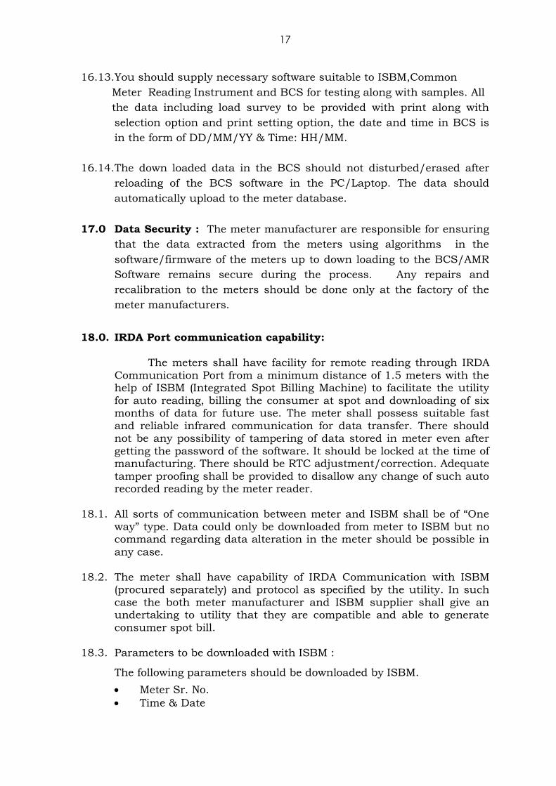
17
16.13. You should supply necessary software suitable to ISBM,Common
Meter Reading Instrument and BCS for testing along with samples. All
the data including load survey to be provided with print along with
selection option and print setting option, the date and time in BCS is
in the form of DD/MM/YY & Time: HH/MM.
16.14. The down loaded data in the BCS should not disturbed/erased after
reloading of the BCS software in the PC/Laptop. The data should
automatically upload to the meter database.
17.0 Data Security : The meter manufacturer are responsible for ensuring
that the data extracted from the meters using algorithms in the
software/firmware of the meters up to down loading to the BCS/AMR
Software remains secure during the process. Any repairs and
recalibration to the meters should be done only at the factory of the
meter manufacturers.
18.0. IRDA Port communication capability:
The meters shall have facility for remote reading through IRDA
Communication Port from a minimum distance of 1.5 meters with the help of ISBM (Integrated Spot Billing Machine) to facilitate the utility
for auto reading, billing the consumer at spot and downloading of six months of data for future use. The meter shall possess suitable fast
and reliable infrared communication for data transfer. There should not be any possibility of tampering of data stored in meter even after
getting the password of the software. It should be locked at the time of manufacturing. There should be RTC adjustment/correction. Adequate
tamper proofing shall be provided to disallow any change of such auto recorded reading by the meter reader.
18.1. All sorts of communication between meter and ISBM shall be of “One
way” type. Data could only be downloaded from meter to ISBM but no command regarding data alteration in the meter should be possible in
any case.
18.2. The meter shall have capability of IRDA Communication with ISBM (procured separately) and protocol as specified by the utility. In such
case the both meter manufacturer and ISBM supplier shall give an undertaking to utility that they are compatible and able to generate
consumer spot bill.
18.3. Parameters to be downloaded with ISBM :
The following parameters should be downloaded by ISBM.
Meter Sr. No.
Time & Date

18
All the parameters specified in scrolling mode along with tamper
indications if any.
ISBM must have facility to download the above data to the base
computer.
Other than above, if manufacturer proposes to record extra parameters, may indicate in their offer.
19.0. Self Diagnostic Features: The bidder shall provide details of self
diagnostic features available and indication on the 3 phase meter for unsatisfactory/non-functioning of the following.
i) Time & calendar.
ii) Real time clock (RTC) battery. iii) All display segments
iv) Non volatile memory.
20.0. Calibration :
The Meter should be factory calibrated and no modification of calibration should be possible at site by any means what so ever. This
is to ensure that the meter cannot be tampered at site. 21.1. TOD TIMINGS:
There shall be provision for at least 8 (eight) TOD time zones for
energy and demand. The number and timings of these TOD time
Zones shall be programmable.
It shall be possible to change the different time zones through
RS 232 port even after installation of meter with special software
and password protection.
TOD Timings in six zones by default shall be as given below.
However software has to be provided to change the TOD zones
whenever required.
TOD 1 - 00.00Hrs. to 06:00Hrs. TOD 2 - 06.00Hrs. to 10:00Hrs.
TOD 3 - 10.00Hrs. to 14:00Hrs. TOD 4 - 14.00Hrs. to 18:00Hrs.
TOD 5 - 18.00Hrs. to 22:00Hrs. TOD 6 - 22.00Hrs. to 24:00Hrs.
Note: The provision for TOD wise bill point active energy and
apparent energy and maximum demand shall be available
on meter-display which will be utilised as and when
necessity arises. However, same should be logged in the
meter memory and be capable of downloading to the BCS
through the CMRI and be available for viewing at the BCS
end.

19
22.0. CONSTRUCTION:
22.1 Meter shall be designed and constructed to be capable of withstanding
all severe stresses and vibration and dust environments likely to be encountered in actual field. All parts that are likely to develop
corrosion shall be effectively protected against corrosion by providing suitable protective coating. The meter shall have proper fixing
arrangement for mounting in meter box.
22.2 The meter Case shall be made up of unbreakable high grade flame
retardant poly carbonate with minimum thickness of 2 mm and of
good di-electric & mechanical strength. Meter case and external
terminal cover should be injection moulded in UV stabilized poly
carbonate. The moulded meter case should not change in colour,
shape, size, dimension when subjected to 72HRS on UV Test. It should
with stand 650Deg C glow wire test and heat deflection test as per ISO
75. The External Terminal Block Cover shall be kept fully transparent.
The meter case and meter cover should be fully transparent,
unbreakable UV stabilized poly carbonate for easy reading of all the
display values/ parameters and should not fade in course of time and
become opaque causing inconvenient in course of time.
22.3 It should be compact and of reliable design to make it immune to
vibrations and shocks in normal transportation and should be capable
of withstanding several stresses likely to occur in actual service. The
latest state of art technology of surface mounting of components etc.
may be used for the purpose. The soldering if any used shall be
protected against dry solders.
22.4. The construction of the meter shall be such as to permit sealing of the
meter cover, the terminal cover etc. independently. It should be
ensured that the internal parts are not accessible for tampering etc.,
without breaking the meter cover and meter seals. The meter cover
should be ultrasonic Welded with the meter base and there shall not
be any fastening arrangements for the same. The ultrasonic welding
should be continuous in nature such that no part of the periphery
shall be left without bonding. This is to ensure that in case of any
attempt to open the cover from the base, there should be visible
evidence of opening/tampering.
22.5 Meters shall be designed and constructed providing reinforced
insulation in such a way as to avoid introducing any danger in use
so as to ensure specially.
i) Personnel safety against electric shock.
ii) Personnel safety against effects of excessive temperature. iii) Protection against spread of fire.
iv) Protection against penetration of solid objects, dust and water.

20
In addition necessary documentary evidence shall be made available by the supplier for having used Industrial Grade components.
Further, meters should be provided with Short circuit current protection
23. Terminals and Terminal block:
23.1 The terminal block shall be of moulded type and shall be fixed to the
extended portion of the meter base. The meter base shall cover the terminal block of its back and sides. It should be non hygroscopic, non
ignitable and with material of good dielectric and mechanical strength. Extended terminal cover shall be provided, to ensure that the internal
parts are not accessible for tampering etc. without breaking seals. A firm connection shall be established within the meter to energize the
voltage circuit. The distance between the end terminal block and the ending of the extended terminal cover shall be a minimum of 2 inches.
23.2. The terminals in the terminal block shall be of adequate length in
order to have proper grip of conductor with the help of screw adjustable metal plates to increase the surface of contact and reduce
the contact resistance. The screws shall have thread size not less than M4 and head having 4-6mm. Diameters. The screws shall not have
pointed ends at the end of threads. All terminals and connecting screws and washers should be of tinned / nickel plated brass material. The terminal block should withstand glow wire test at 960 + 15 ºC and
the terminal should withstand at least 135 ºC. as per IS.
23.3 Sufficient clearance shall be allowed between terminals. Further, the supporting webs between the two terminals of the terminal block should
be sufficiently high to ensure that the two neighboring terminals do not get bridged by dust or it is not possible to have flash over between
adjacent terminals of terminal block.
23.4 The terminals shall be of suitable rating to carry 150% of Imax of 5-30A and made of electro-plated (or tinned) brass and shall be of replaceable
type.
23.5 All connection screws and washers should be tinned/nickel plated brass. The terminal screws shall not have pointed end at the bottom.
All terminals will have two screws. The terminals shall be properly bound in the insulation. Sufficient clearance can be provided between
terminals to avoid possible flash over.
23.6 The terminal block shall have provision with double screws for fixing to the meter board. It shall not be possible to remove the meter from the
hanging screw without removing the screws from the terminal block.
23.7 The extended terminal cover shall be transparent fixed to the meter terminal block by two screws. The screws should not be detachable
from the cover and shall have provision for sealing. The terminal cover extension shall be designed such that cable and cable glands are
covered completely inside the box to avoid mishandling of the cables by unauthorized persons.
21
24.0. Connection diagram: Every meter shall be indelibly marked with a
connection diagram showing the phase sequence for which it is
intended and shall be attached to the inner side of the extended
terminal cover. In case any special precautions need to be taken at
the time of testing the meter, the same may be indicated along with the
circuit diagram. The terminals shall be clearly embossed on terminal
block which is visible from distantly on terminal block for giving
external connections. A diagram of connections should be provided
inside the cover of terminal block.
25.0. Terminal Arrangement : The terminal arrangement and connection
diagram shall be marked in accordance with clause 7.2 of IS 13779 .
Terminal arrangement shall be in sequence RPh(in), RPh(out), YPh(in),
YPh(out), BPh(in), BPh(out), Neutral (in), Neutral(out).
26.0 Fixing arrangement of meter :The meter shall have minimum three
fixing holes, one at the top for mounting and two at the bottom, inside
the terminal cover. The top hole shall be key-hole type on the back
side of the meter base so that hanging screw is not accessible after
fixing meter and it shall be not possible to remove the meter from the
hanging screw without removing the terminal cover and screws behind
the terminal block cover. The lower side fixing holes shall be provided
under ETBC. All the fixing holes shall be designed in such a way that
once meter is mounted; the screw heads shall not be accessible.
27.0 Non Flammability: The terminal block, the terminal cover and the
case shall ensure reasonable safety against spread of fire. They shall not be ignited by thermic over load of live parts in contact with them.
To comply with this these parts shall fulfill the conditions of the glow wire test as per CBIP -304.
28.0 Sealing of meter:
i) Proper sealing arrangement should be provided on the meter to
make it tamper resistant and avoid mishandling by unauthorized persons. The construction of meter shall be such
as to permit sealing of the meter cover in two locations i.e right & left apart from the terminal cover which is detailed elsewhere
in the specification.
ii) The size of the sealing screw must be in such a way to provide one more AP-PDCL security seal along with company seal in the
same screw. The sealing screw should be unidirectional This is to ensure that internal parts are not accessible for tampering
without breaking the seals.
iii) One number separate sealing arrangement to the MD Reset button and separate flap for RS 232 port shall be provided.

22
iv) Bidder shall provide patented seals as per CEA Regulation(2006)
v) The holes for sealing wire shall be minimum 2mm dia .
29.0 Tamper and fraud protection/Monitoring:
29.1 The meter should have tamper and fraud protection features immunity
to external disturbances as per CEA installation and operation of
meters regulations so as to continue to register active and apparent
energy accurately .Some of the conditions are as under .
a) Phase sequence and Phase Reversal: The meter should record
actual consumption correctly irrespective of the phase sequence
and phase reversal.
b) Current Reversal: Correct energy registration even on current
reversal on one or more phases. The reverse indication in the
form of blinking LCD phase icon or LED to indicate which phase
is reverse.
c) Missing potential: Correct energy registration even on non
availability of single or two phases. Meter should remain
functional even when either of any phases or any one phase
along with neutral is available to the meter and record correct
energy.
d) The meter shall continue to record energy as per prevailing
condition even if the neutral is accidentally or intentionally
disconnected.
e) The Meter recording should be insensitive to passage of DC
voltage or should log as an event in the memory as neutral
disturbance. The meter should record energy as per voltage
measured between incoming phase and neutral when DC
signal/voltage is injected on the neutral through a diode/device.
A conformity test on this condition will be carried out at Vref
applied between incoming phase and diode terminal.
f) Indication to show whether meter records consumption in all the
three phases should be available in the display. Non recording
consumption in any one of the phase should be indicated.
g) The meter shall be immune of any abnormal frequency signal or
meter shall log and display as tamper in the event abnormal

23
frequency signal i.e., less than 47.5 Hz or more than 52.5 Hz is
supplied to the meter.
h) Meter shall record energy accurately under the effect of signals
emitted by mobile phone or any other such devices. In
conformity of this, the meter shall be checked under such
influence (10 minutes) for the following conditions:
10% Ib and UPF, 50% Ib and UPF, Ib and 0.8 PF, 120% Ib and
UPF
i) The meters shall be immune to tampering through application of
external magnetic fields at least up to 0.5 Tesla (DC) and 0.2
Tesla +/- 5% (AC) as per CBIP-304. The magnetic test should be
conducted on all three phases.
On application of magnetic interference beyond 0.2 Tesla,
the meter shall record energy at 150% Imax, rated voltage and
UPF as per CBIP-304. The meter is expected to be immune to
such interference and this clause is applicable when
interference level is beyond immunity offered by the meter. The
vendor has to state the level under which meter records energy
as stated above.
j) The accuracy of the meter should not be affected with the
application of abnormal voltage/frequency generating device
such as spark discharge of approximately of 35KV.The meter
shall be tested by feeding the output after exposing it to the
following conditions for 10 minutes:
- On any one of the phase or neutral terminals
- On any connecting wires of the meter
- Voltage discharge with 0-10mm spark gap
- at any place in load circuit
- at proximity of the meter(within 5 cm )
To this effect, a test certificate must be submitted by the bidder
from any government approved NABL LAB/CPRI.The accuracy of the
meter shall be checked before and after the application of the above
device.
Note.1 : The disturbances to be considered are
(1) Harmonics. (2) Voltage dips and short interruptions.
(3) Conducted transients. (4) D.C. and A.C. magnetic fields.
(5) Electro Magnetic fields. (6) Electro static discharge.
(7) Radio frequency interference suppression.

24
Note 2: Especially, special care should have been taken such that DC
& AC magnetic field in proximity of the meter do not damage
or influence the meter performance. Besides, an internal
magnetic shield has to be provided in the meters in this
regard.
29.2. Tamper.
1. Tamper and fraud monitoring should be as per CBIP -304 and also
should comply CEA installation and operation of meters regulations.
2. The tamper indications should be selected and stored in the order
of occurrence in three blocks.
3. In the first block, the voltage missing, voltage unbalance and its
date of occurrence and restorations, with date and time should be
recorded and stored in respective compartments.
4. In the second block the tamper indications for other features like
current circuit short etc., should be recorded.
5. In the third block other tampers are to be stored.
29.3 Generally the meter shall have the following special features to
monitor/ detect tamper and fraud against meter:
a. Meter Cover: In the event the meter is forcibly opened, even by 2
to 4 mm variation of the meter cover, same should be recorded
as tamper event with date & time stamping and the meter
should continuously display that the cover has been tampered.
It is suggested that the manufacturer should develop their
software such that there will be some time delay for activation of
this tamper feature and during that period only the meter cover
should be fitted. The delay in activation of software shall be for
one instance only. After the meter cover is fitted, it shall get
activated immediately without any delay on LCD display in
blinking mode so that it is easily noticed by the meter reader.
The above tamper shall detectable even in power off condition.
The reset of this tamper event shall be in the scope of the
manufacturer only.
b. Unbalance/Missing Potential : The meter should be capable of
recording occurrence of a missing potential and its restoration
with date and time of first such occurrences and last restoration
along with total number of such occurrences during the above
period phase wise.

25
The threshold voltage for voltage missing indication may be
165V for 240 V meters and shall applicable only if phase is
available. The threshold voltage for voltage unbalance indication
may be 30 % of Vref between phase to phase and phase to
neutral.
c. Current Unbalance: The meters shall indicate load unbalance
over and above 30% between the phases for loads above 10% of
Ib.
d. Current Circuit Short: The meter shall be capable of detecting
and recording occurrences and restoration of shorting of any
one or two phases of current, with date and time of occurrence
and restoration. Bidders may indicate logic for the above tamper
detection and logging scheme.
e. Magnetic Tamper: The meter should record energy with in
specified limit as per CBIP-304 latest amendments in presence
of stray magnetic field and record the influence of abnormal
magnetic field with date and time in the memory.
f. Neutral Disturbance: When the neutral from both incoming and outgoing side are disturbed. Meter shall record correctly in case
AC/DC high frequency signal is injected in the neutral circuit of the meter.
Besides the meter shall not display any nuisance tamper
information on service conditions such as over compensation, leading
PF on one phase and lagging PF on other phase and also switching
operation.
29.4. The No. of tamper information / events for each type of tamper to be
recorded in three blocks under each category is as follows:
Block I: 1. Voltage missing (50)
2. Voltage unbalances (30)
Block II: 3. Current unbalance (50)
4. Current circuit short (10)
Block III: 5. Software (settings and parameters) change – (20) events with
date and time along with parameter changed.
6. Neutral Disturbance (19).
7. Cover opening (1).
8. Magnetic influence events (10)
9. Power failure (30)

26
29.5. A minimum of 200 tamper information (FIFO basis) shall be available
in the memory for retrieval from the meter at any time. The above
tamper in EACH BLOCK information is of First In First Out basis
but the first tamper occurrence with date should appear till the tamper
persist.
29.6. Tamper Information:
After occurrence of any tamper, the tamper display should appear in
the display and the tamper data should remain in memory so that the
occurrence of latest tamper can be retrieved and also seen in the
display at any time.
29.7. Provisions should not be there to clear the tamper information through
CMRI or any other means. Provisions should be made such that first
occurrence of tamper should exist as long as tamper exist in the
circuit.
29.8. The persistence time for detecting any abnormality shall be 300
seconds for occurrence and for restoration & it shall be 30 seconds for
meter cover opening, Magnetic interference and Neutral disturbance.
29.9 In BCS the snap shot feature is to be provided for every meter tamper
data with cumulative Kwh, Kvah, V, I & Date & time at the time of the
tamper occurrence & tamper restoration. A summary report on tamper
events along with its total duration for each type of the events occurred
from the date of manufacturing or installation is to be made available.
as detailed in Sub Annexure-1.
29.10 The Supplier should furnish the details as to how their meter is able to
detect/ protect / recording the above tamper and fraud features with
sketches and phase diagram.
30.0. Responsibility:
30.1. The software suitable to Common Meter Reading Instruments &
ISBMs shall be provided with ordered meters to Common M.R.I/ISBMs
manufacturer approved by Board as detailed in CBIP - 304 and as
detailed elsewhere in the Purchase Order.
30.2 Besides, they should supply the communication cable for downloading
the data from meters with RS 232 port terminating into a 9 pin „D‟ type
male connector with a cable of minimum 1000 mm +/- 10 mm length
at free of cost at for every 500 meters lot for down loading the data to
Common Meter Reading Instruments along with the supplies of meter,
failing which the supply will not be taken into stock.

27
30.3 A detailed list of bought out items which are used in the
manufacturing of the meter should be furnished indicating the name
of firms from whom these items are procured is to be submitted along
with the technical bid.
30.4 The meter shall be completely factory sealed except the terminal block
cover. The provision shall be made on the Meter for only two seals to
be put by utility user. The Terminal cover should be transparent with
one side hinge with sealing arrangement.
31.0 Technical specification for pilfer proof box to house the meter.
i. The box shall be weather proof made out of transparent
Polycarbonate with flame retardant properties.
ii. It shall be capable of withstanding temperatures of boiling water for 5 minutes continuously without distortion or softening. The
thickness of the box shall not be less than 3mm on the load bearing side (i.e., back side of the box) and other sides, door and
roof shall not be less than 2.5mm. The box shall have its roof tapering down to both sides for easy flow of water.
iii. The Boxes shall generally comply with the provisions of IS 5133
and IEC60 695. The boxes shall be suitable for outdoor/indoor
application. The outdoor box shall have its roof designed for easy flow of rain water without any stagnation on the box. The
box shall be with good workmanship.
iv. The dimensions of the box shall be such that there is a minimum clearance of 50 mm on all sides, 25mm clearance on
the front and 10mm on the back of the meter then the meter is fixed in the box.
v. Soft rubber gaskets shall be provided all around wherever
required for protection against entry of dust and water. It shall comply with IP-33.
a) Colour : Fully transparent
b) The contents of the box are as follows
vi Internal hinges : A minimum of 2 nos. internal hinges well protected against corrosion shall be provided. The hinges of the
door should be concealed and they shall be fixed to the flanges provided to the base and cover of the box in such a manner that
the door opens by a minimum of 120 degrees.
vii Handle : Suitable handle or knob shall be provided for opening of the box door.
viii Fixing arrangement : The meter base supports inside the box
are raised by about 10 mm in the box for ease of wiring. While
28
fixing the meter screws should not protrude outside. For fixing
the box to wall or wooden board 4 nos. key holes of minimum 6 mm dia shall be provided at the four corners of the meter box.
The meter is to be installed in the box and the box in the assembled condition shall have provision to fix it to a pole or on
wall.
xix Latch : The door shall be provided with a GI latch or a „U‟ clamp to secure it with the base of the box.
x Sealing arrangement : The box shall have provision for
minimum 2 nos. seals to make it fully tamper resistant.
xi Inlet Outlet: Suitable circular holes shall be provided on the left of the box for inlet/right side of the box for outlet with brass
or fire resistance high grade engineering plastic glands securely fixed to the box on both sides by check nuts. The incoming and
outgoing cables shall be clamped to the inside base of the meter box to ensure fixing of the cable. Cable glands shall be
collapsible type so that there shall be no gap after tightening.
xii Printing : The letters “AP-PDCL” and the P.O. No. and date shall be engraved / etched on Metallic lable fixed on the top cover
of the box. The name of the manufacture shall be engraved on the bottom half of the box. A blank sticker shall also be fixed on the meter box for use of field staff to indicate Service No. etc.
xiii The fixing arrangements shall not be complex and it shall be
easily approachable for connections when the door is open and is completely tamper resistant once it is sealed.
xiv The dimensional drawing giving details of meter box shall be
enclosed in the bid.
32. Guaranteed technical particulars:
The guaranteed technical particulars as detailed in the specification Annexure-I & II shall be guaranteed and a statement of guaranteed
technical particulars shall be furnished in the format along with the bid without which the Bid will be treated as Non-Responsive.
32 TESTS:
32.1 Type tests :
32.2 Meters:
The type test certificates for all tests as per IS: 13779-1999/ Relevant
IEC Standard (latest amendments) will be furnished along with tender.
Type test certificates from any one of the standard laboratories such as
NPL/CPRI/ NABL accredited govt laboratories alone shall be
considered.

29
The type test reports can pertain to similar type of materials with
similar or higher capacity current rating. One copy of type test reports shall be furnished with the Bid. The date of type tests shall be not
older than 3 years from the date of opening of the tender. The type testing should be on three samples if type test reports submitted are
as per IS: 13779/99 or on one or more samples if the type test reports submitted are as per CBIP No. 304 The Bids received without type
test reports will be treated as Non-responsive.
32.3 Additional type tests
In addition to the test mentioned in 13.1.1, above the supplier shall
have to furnish the following type test reports:
a. DC influence test as per IS: 13779-1999 or IEC 62053-21 in phase circuit
b. The test of influence of supply voltage shall be carried out as per
clause No.12.7.2.1 of IS: 13779-1999 except the interruption time should be variable from 10 msec to 5 sec instead of fixed
time.
c. Test of voltage variation as per this specification
d. Compliance of anti-tamper features as per this specification
e. The meter shall withstand impulse voltage test at the rated impulse voltage of 10 kV as per IEC 62052-11:2003
f. External AC/DC magnetic influence test as CBIP -304.
g. A 35 KV Spark discharge test certificate must be submitted by
the bidder from any Government NABL/CPRI Lab as per clause no10.1.K.The accuracy of the meter shall be checked before and
after the application of the above device.
32.4. The type test certificates of the above additional tests shall also be submitted along with the bid. The following information should be
clearly mentioned in the type test reports.
i) Type of display ii) Details of Shunts/CT used in main neutral circuit
iii) Accuracy at different loads and PF for all phases separately.
The bid will be made non-responsive if the bidder fails to furnish
the above type tests and additional type tests reports not more than 3
years old on the date of bid submission.
32.5 Tests for boxes: The following tests are to be conducted on the box at any independent laboratory and test reports are to be furnished along
with tender schedule. Manufacturing shall be started after approval of test reports and drawing approval.

30
i) Test of material identification ii) Test for mechanical strength as per IS 14772.
iii) Test for water absorption as per IS 14772. iv) Test for stability at high temperature as per IS 14772.
v) Test for withstanding temperature boiling water for 5 minutes continuously for non-distortion or softening of
material as per IS 14772. vi) Glow wire test as per CBIP Technical Report No.304.
33. Acceptance and routine tests.
33.1 Meters
33.1.1. Acceptance Tests:
Samples picked up by the inspecting officer for acceptance tests
shall be first subjected to „soaking‟ at 70 +/- 2 Deg. C for four hours. After normalizing the acceptance tests as stipulated in CBIP (with latest
amendments) and IS shall be carried out by the supplier in presence of purchaser‟s representative. Also the following additional tests are
carried out on mutually agreed quantity of meters from each lot offered for inspection.
i) Shock Test. ii) Vibration Test.
iii) Magnetic induction of external origin (AC&DC). iv) Tamper & Fraud protection as specified in this
specification v) Voltage variation test as per this specification
vi) Test of no load condition at 70% and 120% of rated voltage. The minimum test period shall be as per cl- 8.3.2
of IEC: 62053-21-2003. vii) Test of DC components in AC circuits – The limits of
variation in percentage error shall be 3.0% for class 1 meter at Imax/sq.root of 2 and UPF as per IS:13779.
viii) Diode injection test. ix) Accuracy test under the anti tamper conditions as
specified in this specification. x) Test for least count.
xi) Test for time taken for down loading data to CMRI & to BCS.
xii) Test on communication capability & software compliance. xiii) Verification of tamper logics and verification of display
parameters. xiv) Permanent magnet test.
xv) Test of application of abnormal voltage/frequency generating devices as per this specification.
xvi) Additional acceptance tests shall include Surge withstand (SWC), Lightning impulse and HF disturbance as per IEC
62052-11. For these specific tests, one sample meter per order from one of the offered lot shall be subjected to
31
SWC/other semi-destructive tests. Meters after tests shall
not be used
For sampling plan for pre-dispatch inspection, maximum
lot size of 10,000 meters shall be considered for acceptance test as per IS:13779/99.
33.1. 2. Routine Tests: All the routine tests as stipulated in IS and in
addition tamper and fraud protection tests as specified in the specification. shall be carried out and test certificates shall be
furnished for approval of the purchaser.
33.1.3. The routine test certificates for the following shall be furnished for approval of the purchaser.
i. Physical verification of dimension of the box.
ii. Compatibility of the box for housing the meter ensuring ease of connecting and the reading the meter.
34.0 Test Reports / Test Certificates:
34.1 Record of routine test reports shall be maintained by the Bidder at his
works for periodic inspection by the purchaser‟s representative. 34.2 . Test certificates of tests conducted during manufacture shall be
maintained by the Bidder. These shall be produced for verification as and when desired by the purchaser.
35.0. Test Facilities:
The tests shall be carried out as per relevant Standards and test
certificates shall be furnished for approval. The Bidder shall indicate the details of the equipment available with him for carrying out the
various tests as per relevant Standards. The bidder shall indicate the sources of all materials.
Note: The Meters used for conducting tests shall be calibrated
periodically at reputed Government Accredited Test Laboratories and test certificates shall be available at works for verification by
purchaser‟s representative.
36.0. Inspection:
36.1 The inspection may be carried out by the purchaser at any stage of manufacture. The manufacturer shall grant free access to the
purchaser's representative at a reasonable time when the work is in progress. Inspection and acceptance of any equipment under this
specification by the purchaser, shall not relieve the supplier of his obligation of furnishing the equipment in accordance with the
specification and shall not prevent subsequent rejection if the equipment is found to be defective.

32
36.2 All acceptance tests and inspection shall be made at the place of
manufacturer unless otherwise especially agreed upon by the Bidder and purchaser at the time of purchase. The Bidder shall afford the
inspector representing the purchaser all reasonable facilities without charge, to satisfy him that the equipment is being furnished in
accordance with this specification.
36.3 The supplier shall keep the purchaser informed in advance, about the manufacturing programme so that arrangement can be made for
inspection.
36.4 The purchaser reserves the right to insist for witnessing the acceptance/routine testing of the bought out items. The supplier shall
give 15 days for local supply/30 days in case of foreign supply advance intimation to enable the purchaser to depute his representative for
witnessing the acceptance and routine tests.
36.5 The purchaser reserves the right to get type test any meter, or Box from any of the lots offered for inspection received at any Destination
Stores at purchaser‟s expenses and clause 8.0 (Section-V) applies for any failure to pass tests.
36.6 NOTE FOR FOREIGN BIDDERS: The Bidder shall indicate the name
(s) of reputed inspection agencies and the inspection charges clearly for each lot. The inspection charges will be borne by the supplier. However the purchaser reserves the right to appoint at his cost any
inspection agency to carry out the inspection.
Training: Training for two of purchaser‟s engineers shall be imparted by the bidder. All expenses towards training of purchaser‟s engineers
shall be borne by the bidder. The expenditure towards travel and incidentals including accommodation is to purchasers account.
37.0. Testing after receipt at stores:-
From meters supplied to Stores, AP-PDCL will pick up samples at random @ 1 No. meter for every lot of 5,000 Nos. or part thereof. These
samples will be tested for acceptance tests as decided by AP-PDCL at NABL Accredited Government Laboratory in the presence of
representatives of supplier and AP-DCL as per relevant IS/IEC/CBIP and AP-DCL specifications at suppliers cost. The samples of
subsequent lot shall be tested at different NABL Accredited Government Laboratories. If the sample meter fails in the testing again
two sample meters will be picked up at random from the stores and tested. If the meter fails in the above tests the entire lot will be
rejected. If acceptance test fails in subsequent lots, the PO will be terminated. All the expenses for testing of the meters shall be borne by
the supplier.
38.0 QUALITY ASSURANCE PLAN :
38.1 The Bidder shall invariably furnish the following information along with his bid, failing which his bid shall be liable for rejection.

33
Information shall be separately given for individual type of material
offered.
(i) The structure of organization. (i) The duties and responsibilities assigned to staff ensuring quality
of work. (ii) The system for purchasing, taking delivery and verification of
materials. (iii) The system for ensuring quality of workmanship.
(iv) The quality assurance arrangement shall conform to relevant requirements of ISO 9001 or 9002 as applicable.
(v) Statement giving list of important raw materials names of sub-suppliers for the raw materials, list of standards according to
which the raw materials are tested. List of test normally carried out on raw materials in presence of Bidder's representative,
copies of test certificates. (vi) Information and copies of test certificates as in (i) above in
respect of bought out accessories. (vii) List of manufacturing facilities available.
(viii) Level of automation achieved and list of areas where manual processing exists.
(ix) List of areas in manufacturing process, where stage inspections are normally carried out for quality control and details of such
tests and inspections. (x) Lists of testing equipment available with the bidder for final
testing of equipment specified and test plant limitation. If any,
vis-a-vis the type, special acceptance and routine tests specified in the relevant standards. These limitations shall be very clearly
brought out in schedule of deviations from specified test requirements.
38.2. The contractor shall within 30 days of placement of order, submit
following information to the purchaser.
i. List of raw materials as well as bought out accessories and the names of sub-suppliers selected from those furnished along with
offers. ii. Type test certificates of the raw materials and bought out
accessories if required by the purchaser. iii. Quality assurance plan (QAP) with hold points for purchaser's
inspection. The quality assurance plan and purchasers hold points and notification points shall be discussed between the purchaser
and Bidder before the QAP is finalized.
38.3. The contractor shall operate systems which implement the following.
(i) Hold Point: A stage in the material procurement or workmanship process beyond which work shall not proceed without the
documental approval of designated individuals or organizations. The purchaser‟s written approval is required to authorize work
to progress beyond the hold points indicated in approved quality plans.

34
(ii) Notification Point: A stage in material procurement or
workmanship process for which advance notice of the activity is required to facilitate witness. If the purchaser does not attend
after receiving documented notification in accordance with the agreed procedures and with the correct period of notice then
work may proceed.
38.4. The contractor shall submit the routine test certificates of bought out accessories and central excise passes for raw material at the time of
routine testing if required by the purchaser and ensure that the Quality Assurance requirements of this specification are followed by
the sub-contractors.
38.5. The quality assurance programme of the contractor shall consist of the quality system and quality plans with the following details.
(i) Quality System:
The structure of the organization
The duties and responsibilities assigned to staff ensuring quality of work.
The system for purchasing, taking delivery and verification of materials.
The system for ensuring quality workmanship. The system for control of documentation. The system for the retention of records.
The arrangement for the contractor‟s internal auditing. A list of the Administration and work procedures required to
achieve and verify Contract‟s quality requirements. These procedures shall be made readily available to the project
Manager for inspection on request.
(ii) Quality Plans:
An outline of the proposed work and programme sequence. The structure of the contractors organization for the
contract. The duties and responsibilities assigned to staff ensuring
quality of work. Hold and Notification points.
Submission of Engineering documents required by the specification
The inspection of materials and components on receipt. Reference to the Contractor‟s Work Procedures appropriate to
each activity. Inspection during fabrication / Construction.
Final Inspection and test.
39.0. Documentation:
39.1 All drawings shall conform to International Standards Organization (ISO) `A' series of drawings sheet/India Standards Specifications IS:656. All
35
drawings shall be in ink and suitable for micro filming. All dimensions
and data shall be in S.I. Units.
39.2 List of drawings and documents:
The bidder shall furnish the following along with bid
i. Two sets of drawings showing clearly the general arrangements, fitting details, electrical connections etc.
ii. Technical leaflets (user manual) giving operating instructions. iii. Three copies of dimensional drawings of the box for each quoted
item.
39.3 The manufacturing of the equipment shall be strictly in accordance with the approved drawings and no deviation shall be permitted without the
written approval of the purchaser. All manufacturing and fabrication work in connection with the equipment prior to the approval of the
drawing shall be at the supplier's risk.
10.4 Approval of drawings/work by purchaser shall not relieve the supplier of his responsibility and liability for ensuring correctness and correct
interpretation of the drawings for meeting the requirements of the latest revision of application standards, rules and codes of practices. The
equipment shall conform in all respects to high standards of engineering, design, workmanship and latest revisions of relevant standards at the time of ordering and purchaser shall have the power to
reject any work or materials which, in his judgment is not in full accordance therewith.
39.5 The successful Bidder shall, within 2 weeks of notification of award of
contract, submit three sets of final versions of all the drawings as stipulated in the purchase order for purchaser's approval. The purchaser
shall communicate his comments/approval on the drawings to the supplier within two weeks. The supplier shall, if necessary, modify the
drawings and resubmit three copies of the modified drawings for their approval. The supplier shall within two weeks, submit 3 prints and two
good quality report copies of the approved drawings for purchaser's use.
39.6 Eight sets of operating manuals/technical leaflets shall be supplied to each consignee for the first instance of supply.
39.7. One set of routine test certificates shall accompany each dispatch
consignment.
39.8. The acceptance test certificates in case pre-dispatch inspection or routine test certificates in cases where inspection is waived shall be got
approved by the purchaser.
40.0. Sample:
40.1 The Tenderer should supply six Nos. sample meters as per Specification
along with their tender offer for evaluation and testing the meters in

36
Government NABL accredited laboratory at the cost of the bidder. Out
of SIX samples, one sample is to be submitted without welding. The
software for CMRI & BCS and memory mapping including
communication probe should be submitted along with offer for testing
the sample meter
40.2 The sample meter shall comply with all tests in all respect to this
specification. In case sample meters are found not conforming to the
requirements both in hardware and soft ware, the price bid of the offer
shall not be opened and offer will be rejected.
40.3. A team of officers will also be deputed to the factory premises of the
bidder to assess the manufacturing quality and facility and to pick up
two more samples of the same range/similar specification from the
manufacturing line or from the storage place for testing at CPRI at
bidder‟s cost before or after placing order. In case sample meters are
found not conforming to the requirements both in hardware and soft
ware, the purchase order will be cancelled and the vendor will be black
listed.
40.4. The time required for down loading the data as confirmed by the
bidder will also be tested at testing lab.
40.5. After six months of installations of the meters of the successful
bidders, meters in premises of consumers, will be released and taken
out for testing in NABL accredited Govt laboratories at the cost of
AP_PDCL. The bidder‟s representative can also be present at the time
of release and testing of meters. If the meters are found to be defective
such supplies will be closed, B.G invoked and EMD forfeited. The firm
will not be eligible for participating for any tender in AP_PDCL for the
next three years.
41.0 Packing & Forwarding:
41.1 The equipment shall be packed in crates suitable for vertical/horizontal transport as the case may be, and suitable to withstand handling during
transport and outdoor storage during transit. The supplier shall be responsible for any damage to the equipment during transit, due to
improper and inadequate packing. The easily damageable material shall be carefully packed and marked with the appropriate caution symbol.
Wherever necessary, proper arrangement for lifting, such as lifting hooks

37
etc., shall be provided. Any material found short inside the packing
cases shall be supplied immediately by supplier without any extra cost.
41.2 Each consignment shall be accompanied with a detailed packing list containing the following information.
a. Name of the consignee.
b. Details of consignment. c. Destination.
d. Total weight of consignment. e. Handling and packing instructions.
f. Bill of Material indicating contents of each package.
41.3 The supplier shall ensure that the packing list and bill of material are approved by the purchaser before dispatch.
41.4 The packing shall be done as per the manufacturer's standard practice.
However, he should ensure the packing is such that, the material should not get damaged during transit by Rail/Road.
41.5 The marking on each package shall be as per the relevant Standards and
shall also contain.
42.0 Supervision Services: Nil. The Purchaser will arrange for unloading of the consignments at the
destination stores.
43.0 Mandatory spares & Tools:
The bidder shall give the list of items and shall keep a reasonable stock of the same, during the warranty period.
44.0 Technical deviations:
Any deviation in Technical Specification as indicated in Section-III shall
be specifically and clearly indicated in the schedule of deviation format – Schedule – „A‟.
45.0 Guarantee:
The material should be guaranteed for satisfactory operation for a
period of 5 years from the date of receipt of material at destination stores by the consignee in good condition. During the guarantee period
if the meter while in its normal operation is found defective, it shall be replaced by the supplier with a new meter free of cost within 15 days.
If the meter is not replaced within 30 days of intimation the supplier should note that the guarantee period will be extended to that extent
by the number of days delayed beyond 30 days. If the tenderer does not replace within 180 days the cost of the meter(s) will be recovered
from the existing bills/ future bills/ Bank Guarantees available AP_PDCL.

38
46.0 General:
a) Principle of operation of the meter, outlining the methods and
stages of computation of various parameters starting from input voltage and current signals including the sampling rate if
applicable shall be furnished by the bidder.
b) The bidder shall indicate the method adopted to transform the voltage and current to the desired low values with explanation
on devices used such as CT, VT or Potential divider as to how they can be considered superior in maintaining ratio and phase
angle for variation of influence quantities during its service period.
c) The bidder shall furnish details of memory used in the meter.
d) Details of testing facilities:
The manufacturer laboratory must be well equipped for testing of the
meters. They must have computerized standard power source and standard equipment calibrated not later than a year (or as per
standard practice). The details of testing facilities available for conducting (a) The routine tests and (b) Acceptance tests shall be
furnished in a statement. Bids without these details will be treated as Non responsive.

39
ANNEXURE – I
GUARANTEED TECHNICAL PARTICULARS FOR METERS
Sl.No Technical Particulars Details
1 Make & Type
2 Applicable standard is 13779/1999 (amended up to date) – y/n
3 Accuracy class 1.0 – y/n
4 Rated voltage 3x240 v(+20% to -40%) – y/n
5 Basic current (ib) 5 amp – y/n
6 Maximum continuous current(Imax) 45 A– y/n
7 Starting current 0.2 % of Ib – y/n
8 Short time over current 30 Imax – y/n
9 Display provided with backlit LCD type– y/n
10 Seven number of digits – y/n
11 Size of digits 10x5 mm minimum
12 Power consumption of voltage circuit 1W, 4VA – y/n
13 Power consumption of current circuit 1VA for ct/shunt – y/n
14 Kva/Kw MD provided – y/n
15 Integration period of MD 30 min – y/n
16 Rs232 communication port provided – y/n
17 Material of base and cover polycarbonate – y/n
18 All anti-tamper features as per tender spec are provided – y/n
19 Type of backup power provided -super capacitor(y/n)
20 For internal battery/super capacitor activation push button is provided – y/n
21 Provision of MD reset (auto) with monthly/even/odd month
reset date and time – y/n
22 Extended transparent terminal block cover (50mm) is
provided with logo & sealing arrangement – y/n
23 Guarantee of five years from date of receipt at stores is
complied – y/n
24 Minimum internal diameter of terminal holes 8.5mm – y/n
25 In-house testing facilities for conducting acceptance tests as
per IEC / IS and this specification – y/n
26 Availability of calibrated ERS meter of class 0.05-0.1 accuracy
with valid calibration certificate – y/n
27 Data retention for a long period (10 years) under power off condition – y/n
28 Four decimal resolution in calibration mode – y/n
29 Icon for current reversal, phase wise – y/n
30 Fixing arrangement of meters as per spec– y/n
31 Furnish principle of operation of meter outlining the methods and stages of computations of various parameters starting
from input voltage and current signals including sampling rate if applicable.(as a document hard & soft copy) y/n
32 Manufacturing activities as per specification submitted (details shall be submitted separately in sealed cover along
with the offer)
33 Whether type tested – y/n
34 Type test report no
35 Whether QAP submitted - y/n

40
36 RTC temperature compensated 0-50˚c – y/n
37 Facility for correcting RTC drift thro CMRI/Remote – y/n
38 RTC make & Accuracy (minutes/year)
39 PCB is manufactured by SMT and without any wire loops and
joints - y/n
40 TOD time zones are provided for energy & demand as per
specification - y/n
41 Internal battery guarantee/undertaking
is submitted - y/n
42 Whether voltage & current circuit are solidly connected inside
the meter body without any links - y/n
43 Whether type test reports,manual along with copy of the same
in two CDs is submitted - y/n
44 Sample meters as per tender documents are submitted out of these one samples should be without ultrasonic welding to
confirm constructional features of the meters- y/n
45 As per technical specification spark discharge test at 35 kv is
carried out - y/n
46 As per technical specification least count test is carried out –
Y/N
47 Details of CT/shunt provided - y/n
48 Number of pulses/Kwh&Kvarh count (p.u)
49 Time taken to function upon powering up of meter
50 Details of terminal blocks provided A) glow wire test of polycarbonate is carried out - Y/N
51 Memory capacity in MB.
52 Non volatile memory retention time in absence of power
53 Over all dimensions & weight
54 Sealing provision for cover, terminal cover, communication port - y/n
55 Protection from lightning & HV surge - y/n
56 Range for safe operation
57 Total number of tamper events available
58 CMRI/BCS software as per specification - y/n
59 Availability of self diagonsitic features - y/n
60 Value upto which meter can withstand direct current in AC
circuits without getting CT saturated resulting in measurement error of more than permisble limit
61 Magnetic immunity level for AC/DC
62 Compliance to protection from tamper& fraud - y/n
63 Whether the meter can record energy as per voltage measured
between incoming phase & neutral terminal when dc signal is injected on neutral terminal through a diode - y/n
64 Availability of SMT manufacturing at the works - y/n
65 Availability of in-house design, development & manufacturing facilities-y/n
66 PCB material glass fr-4 grade (yes/no), if no furnish details
67 Short time over current withstands capacity for one half cycles at reference frequency-(in terms of i-max.)
68 Display sequence as per specification - y/n

41
69 reading provided in the meter is direct - y/n
70 Confirmation to the effect that meter does not get damaged
even if 500v (ac) is applied for 5 minutes between phase and neutral and continue to record correctly after restoration of normal supply - y/n
71 Can meter perform within class 1.0 accuracy upto 600% Ib
for pf range 0.5 lag, 0.8 lead & unity - y/n
72 Whether meter can record energy if voltage falls upto 50% of
rated voltage at Ib to Imax - y/n
73 Power consumed for display during power off condition (w)
74 Degree of protection ip-51 - y/n
75 Data transfer time a. meter to cmri (min).
b. cmri to bcs (min). c.meter reading to ISBM

42
ANNEXURE – II
TECHNICAL PARTICULARS OF BOX
Sl.
No.
Characteristics
I. 1. Manufacturer‟s name
2. Material used for box body
3. Material withstanding temperature
4. Dimensions of box (l x w x h)
5. Thickness (mm)
II. 1. Color
2. No. of Hinges
3. Handle provision
4. Sealing Arrangements
5. Inlet & Outlets
6. Gasket
a) Whether gasket is provided for door b) Material of the gasket
36. Suitable for outdoor installation

43
ANNEXURE – III
COMPONENT SPECIFICATIONS AND MANUFACTURERS:
All the materials and electronic power components used in the
manufacture of the meter shall be of highest quality and reputed makes like
given as under so as to ensure higher reliability and sustained accuracy.
1. Current Transformers:
The Meters should be with the current transformers as measuring
elements. The current transformer should withstand for the clauses under
5&9 of IS- 13779 /1999 The current transformer should withstand for the
clauses under 5&9 of IS-13779 /1999.
2. Measurement or computing chips:
The measurement or computing chips used in the Meter should be
with the Surface mount type along with the ASICs.
USA : Teridian, Anolog Devices,Cyrus Logic,Atmel, Philips
Dallas, ST, Texas Instruments ,Renesas
Germany : Siemens
South Africa : SAMES
Japan : NEC
Taiwan : Prolific Technology
3. Memory chips:
The memory chips should not be affected by external parameters like
sparking, high voltage spikes or electrostatic discharges. Meter shall have
non volatile memory (NVM). No other type of memory shall be used for data
recording and programming. (The life of the NVM is highest) There shall be
security isolation between metering circuit, communication circuit, and
power circuit.
USA : Teridian, Atmel, National Semiconductors, Texas
Instruments, Philips, ST, Renesas, Microchip.
Japan : Hitachi
Germany : Siemens
Taiwan : Prolific Technology
4. Display modules:-
a) The display modules should be well protected from the external UV
radiations.

44
b) The display visibility should be sufficient to read the Meter mounted at
height of 0.5 meter as well as at the height of 2 meters (refer 3.2 d for
Viewing angle). c)The construction of the modules should be such that
the displayed quantity should not disturbed with the life of display .d)
It should be trans reflective HTN or STN type industrial grade with
extended temperature range.
Hongkong : Genda
Singapore : Bonafied Technologies,Holtek,Haijing.
Korea : Advantek
Japan : Hitachi,Sony.
Taiwan : Prolific Technology
5. Communication Modules:
Communication modules should be compatible for the two ports (one
for IRDA port for communication with meter reading instruments & the other
for the hardwired RS-232 port to communicate with various modems for
AMR).
USA : National Semiconductors HP, Optonica, Agillant,Texas Instruments, Maxim.
Holland / Korea : Phillips
Japan : Hitachi
Taiwan : Ligitek, Everlight, Prolific Technology
6. Power supply:
The power supply should be with the Capabilities as per the relevant
standards. The power supply unit of the meter should not be affected in case
the maximum voltage of the system appears to the terminals due to faults or
due to wrong connections. It should not also be affected by magnet -SMPS
Type.
7. Electronic Components:
The active & passive components should be of the surface mount type
are to be handled & soldered by the state of art assembly processes.
USA : National Semiconductors,Atmel, Philips, Texas

45
Instruments, BC Component,Fairchild.
Japan : Hitachi, Taiyo Yuden, Oki, Toshiba,AVZ or Ricon
Korea : Samsung
Japan : Panasonic, Toshiba,Fairchild,PEC,CTR
Germany : Vishay, Epcos & NSC,Yageo
Taiwan : Prolific Technology
8. Mechanical parts:
a) The internal electrical components should be of electrolytic copper & should be protected from corrosion, rust etc.
b) The other mechanical components should be protected from rust, corrosion etc. by suitable plating/painting methods.
9. Battery:
Maintenance free Lithium battery of long life of 10 years. Only non
rechargeable battery should be used for RTC as well as display in
absence of Power, since the life & Reliability of these are better than
the rechargeable batteries.
Makes
USA : Maxell,Varta,Tedirun, Sanyo or National
Japan : Panasonic,Sony , Mitsubishi,Sanyo
France : Saft
Korea : Tekcell.
10. RTC & Micro-controller-The accuracy of RTC shall be as per relevant IEC / IS standards.
USA : ST, Teridian, Philips, Dallas, Atmel, Motorola, Microchip, Texas Instruments, Holtek, IDT,
Renesas. Japan : NEC or Oki,Epson.
Malaysia : Intersil.
Taiwan : Prolific Technology
11. P.C.B.:
Glass Epoxy, fire resistance grade FR4, with minimum thickness 1.6
mm if 2 layer and 1.2 mm if 4 layer or more.
Japan : Hitachi, Taiyo Yuden, Oki, Toshiba,AVZ or Ricon
Korea : Samsung
Japan : Panasonic, Toshiba,Fairchild,PEC,CTR
Germany : Vishay, Epcos & NSC,Yageo
Taiwan : Prolific Technology