technical specification for - optcl...vol-ii-technical specification for insulators- e10 page 5 5....
TRANSCRIPT

VOL-II-Technical Specification for Insulators- E10 Page 1
ODISHA POWER TRANSMISSION CORPORATION LIMITED
TECHNICAL SPECIFICATION
FOR
DISC / PORCELAIN LONG ROD/ SILICON RUBBER HOUSED COMPOSITE
INSULATORS FOR SUBSTATION AND TRANSMISSION LINE WORKS

VOL-II-Technical Specification for Insulators- E10 Page 2
INSULATORS
TECHNICAL SPECIFICATION FOR DISC / PORCELAIN LONG ROD INSULATORS FOR SUBSTATION AND
TRANSMISSION LINE WORKS.
1.0 SCOPE.
1.1 This specification provides for design, manufacture, engineering, inspection and testing before dispatch,
packing and delivery FOR (destination) for Indian manufacturers of disc / porcelain long rod Insulators as
per technical requirements furnished in this specification.
These insulators are to be used in suspension and tension insulator strings for the suspension and
anchoring of the conductors on EHV transmission line towers.
1.2 Following are the list of documents constituting this package.
(i) Technical specification.
(ii) Technical data sheet.
(iii) Drawings of insulators
1.3 All the above volumes along with amendments there of shall be read and interpreted together. However, in
case of a contradiction between the “Technical Specification” and any other volume, the provisions of this
volume will prevail.
1.4 The insulators shall conform in all respects to high standards of engineering, design, workmanship and
latest revisions of relevant standards at the time of offer and purchaser shall have the power to reject any
work or material which in his judgment, is not in full accordance therewith.
2.0 STANDARDS:
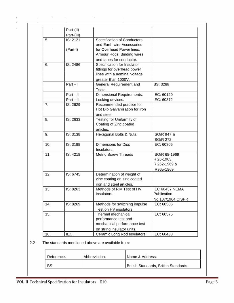
2.1 Except as modified in this specification, the disc/porcelain long rod insulators shall conform to the following
Indian Standards, which also includes latest revisions and amendments if any. Equivalent International and
Internally recognized standards to which some of these standards generally correspond are also listed
below.
Sl. No. Indian Standard Title. International Standard.
1. IS: 206 Method for Chemical Analysis
of Slab Zinc.
2. IS: 209 Specification for Zinc. BS: 3436
3. IS: 731 Porcelain insulators for BS: 137(I&II);
overhead power lines with a IEC 60274 IEC 60383
normal voltage greater than
1000V
4. IS: 2071 Part-(I) Method of High Voltage Testing.
VOL-II-Technical Specification for Insulators- E10 Page 3
Part-(II)
Part-(III)
5. IS: 2121 Specification of Conductors
and Earth wire Accessories
(Part-I) for Overhead Power lines.
Armour Rods, Binding wires
and tapes for conductor.
6. IS: 2486 Specification for Insulator
fittings for overhead power
lines with a nominal voltage
greater than 1000V.
Part – I General Requirement and BS: 3288
Tests.
Part – II Dimensional Requirements. IEC: 60120
Part – III Locking devices. IEC: 60372
7. IS: 2629 Recommended practice for
Hot Dip Galvanisation for iron
and steel.
8. IS: 2633 Testing for Uniformity of
Coating of Zinc coated
articles.
9. IS: 3138 Hexagonal Bolts & Nuts. ISO/R 947 &
ISO/R 272
10. IS: 3188 Dimensions for Disc IEC: 60305
Insulators.
11. IS: 4218 Metric Screw Threads ISO/R 68-1969
R 26-1963,
R 262-1969 &
R965-1969
12. IS: 6745 Determination of weight of
zinc coating on zinc coated
iron and steel articles.
13. IS: 8263 Methods of RIV Test of HV IEC 60437 NEMA
insulators. Publication
No.107/1964 CISPR
14. IS: 8269 Methods for switching impulse IEC: 60506
Test on HV insulators.
15. Thermal mechanical IEC: 60575
performance test and
mechanical performance test
on string insulator units.
16 IEC Ceramic Long Rod Insulators IEC: 60433
2.2 The standards mentioned above are available from:
Reference. Abbreviation. Name & Address:
BS British Standards, British Standards

VOL-II-Technical Specification for Insulators- E10 Page 4
Institution, 101, Pentonvile Road, N-
19 ND,U
IEC / CISPR International Electro technical
commission Electro Technique
International. 1, Rue de verembe
Geneva SWITZERLAND.
IS Bureau of Indian Standards, Manak
Bhavan, 9 Bahadurshah Zafar
Marg, New Delhi-110001, ORISSA
ISO International Organisation for
Standardization. Danish Board of
Standardization Dansk
Standardizing Sraat Aurehoegvej-
12 DK-2900 Helleprup DENMARK.
NEMA National Electric Manufacturers
Association 1`55, East 44th. Street
New York, NY 10017 USA
3.0 PRINCIPAL PARAMETERS.
3.1 DETAILS OF DISC INSULATORS:
3.1.1 The Insulator strings shall consist of standard discs for use in three phases. 50 Hz effectively earthed 33/132/220 KV transmission system of OPTCL in a moderately polluted atmosphere. The discs shall be cap and pin, ball and socket type, radio interference and have characteristics as shown in Table-I and all ferrous parts shall be hot dip galvanized as per the latest edition of IS 2629. The zinc to be used for making sleeves shall be 99.95 % pure.
3.1.2 The size of disc insulator, minimum creepage distance the number to be used in different type of strings, their
electromechanical strength and mechanical strength of insulator string along with hardware shall be as follows:
PRINCIPAL PARAMETERS OF THE DISC INSULATORS:-
Sl. Type of Size of Minimum No. of Electro-
No. String. disc. creepage standard mechanical
Insulator distance of discs strength of
(mm) each disc 132 KV insulator string
(mm), /220 KV/400kV fittings (KN) 1. Single 255 x 145 320 1x9/1x14 /- 70 KN/90 KN
suspension Normal Disc
Insulator 2. Double -do- -do- 2x9/2x14 /- 70 KN/90 KN
suspension. Normal Disc
Insulator 3 Single 255 x 145 430 1x9/1x14 /- 70 KN/90 KN
suspension Antifog Insulator 4 Double -do- -do- 2x9/2x14 /- 70 KN/90 KN
suspension. Antifog Disc
Insulator

VOL-II-Technical Specification for Insulators- E10 Page 5
5. Single Suspension 280 x 145 430 1x10/1x15 /-
120 KN Anti fog Disc insulator
6.
Double
suspension 280 x 145 430 2x10/2x15 /- 120 KN Anti fog Disc insulator
7. Single Tension 305 X 170 475 1x10/1x15/1x25
160 KN Anti fog Disc insulator
8. Double Tension 305 X 170 475 2x10/2x15/2x25
160 KN Anti fog Disc insulator
9. Single Suspension 280 x 145 430 1x10/1x15/1x25
120 KN Anti fog Disc insulator
10.
Double
suspension 280 x 145 430 2x10/2x15/2x25 120 KN Anti fog Disc insulator
3.2 SPECIFICATION DRAWINGS:
3.2.1: The Specification in respect of the disc insulators are described, The specification is for
information and guidance of the bidder only. The drawings to be furnished by the supplier shall be
as per his own design and manufacture and in line with the specification.
4.0 GENERAL TECHNICAL REQUIREMENTS FOR DISC INSULATORS:
4.1 Porcelain:
The porcelain used in the manufacture of the shells shall be nonporous, of high dielectric, mechanical and
thermal strength, free from internal stresses blisters, laminations, voids, forgone matter imperfections or other
defects which might render it in any way unusable for insulator shells. Porcelain shall remain unaffected by
climatic conditions ozone, acid, alkalis, zinc or dust. The manufacturing shall be by the wet process and
impervious character obtained by through vitrification.
The insulator shall be made of highest grade, dense, homogeneous, wet-process porcelain, completely and
uniformly vitrified throughout to produce uniform mechanical and electrical strength and long life service. The
porcelain shall be free from warping, roughness, cracks, blisters, laminations, projecting points, foreign particles
and other defects, except those within the limits of standard accepted practice. Surfaces and grooves shall be
shaped for easy cleaning. Shells shall be substantially symmetrical.
4.1.1 Porcelain glaze:
The finished porcelain shall be glazed in brown colour. The glaze shall cover all exposed parts of the insulator
and shall have a good lusture, smooth surface and good performance under the extreme weather conditions of
a tropical climate. It shall not crack or chip by ageing under the normal service conditions. The glaze shall have
the same coefficient of expansion as of the porcelain body throughout the working temperature range.
4.2 METAL PARTS:
VOL-II-Technical Specification for Insulators- E10 Page 6
4.2.1 Cap and Ball Pins:
Ball pins shall be made with drop forged steel caps with malleable cast iron. They shall be in one single piece
and duly hot dip galvanized. They shall not contain parts or pieces joined together welded, shrink fitted or by
any other process from more than one piece of materials. The pins shall be of high tensile steel, drop forged
and heat-treated. The caps shall be cast with good quality black heart malleable cast iron and annealed.
Galvanizing shall be by the hot dip process with a heavy coating of zinc of very high purity. The bidder shall
specify the grade composition and mechanical properties of steel used for caps and pins. The cap and pin
shall be of such design that it will not yield or distort under the specified mechanical load in such a manner as
to change the relative spacing of the insulators or add other stresses to the shells. The insulator caps shall be
of the socket type provided with nonferrous metal or stainless steel cotter pins and shall provide positive
locking of the coupling.
4.2.2 Security Clips: The security clips shall be made of phosphor bronze or of stainless steel. 4.3 FILLER MATERIAL: Cement to be used, as a filler material be quick setting, fast curing Portland cement. It shall not cause fracture
by expansion or loosening by contraction. Cement shall not react chemically with metal parts in contact with it
and its thickness shall be as small and as uniform as possible.
4.4 MATERIALS DESIGN AND WORKMANSHIP: 4.4.1 GENERAL:
(I) All raw materials to be used in the manufacture of these insulators shall be subject to strict raw
material quality control and to stage testing/ quality control during manufacturing stage to ensure the quality of
the final end product. Manufacturing shall conform to the best engineering practices adopted in the field of
extra high voltage transmission. Bidders shall therefore offer insulators as are guaranteed by them for
satisfactory performance on Transmission lines.
(II) The design, manufacturing process and material control at various stages be such as to give
maximum working load, highest mobility, best resistance to corrosion, good finish elimination of sharp edges
and corners to limit corona and radio interference voltages.
4.4.2 INSULATOR SHELL: The design of the insulator shells shall be such that stresses due to expansion and contraction in any part of
the insulator shall not lead to deterioration. Shells with cracks shall be eliminated by temperature cycle test
followed by mallet test. Shells shall be dried under controlled conditions of humidity and temperature.
4.4.3 METAL PARTS:
i) The pin and cap shall be designed to transmit the mechanical stress to the shell by compression and develop
uniform mechanical strength in the insulator. The cap shall be circular with the inner and outer surfaces
concentric and of such design that it will not yield or distort under loaded conditions. The head portion of the
pinball shall be suitably designed so that when the insulator is under tension the stresses are uniformly
distributed over the pinhole portion of the shell. The pinball shall move freely in the cap socket either during
assembly of a string or during erection of a string or when a string is placed in position.

VOL-II-Technical Specification for Insulators- E10 Page 7
ii) Metal caps shall be free from cracks, seams, shrinks, air holes, blowholes and rough edges. All
metal surfaces shall be perfectly smooth with no projecting part or irregularities, which may cause corona. All
load bearing surfaces shall be smooth and uniform so as to distribute the loading stress uniformly. Pins shall
not show any microscopically visible cracks, inclusions and voids.
4.4.4 GALVANIZING:
All ferrous parts, shall be hot dip galvanized in accordance with IS: 2629. The zinc to be used for galvanizing
shall conform to grade Zn 99.95 as per IS: 209. The zinc coating shall be uniform, smoothly adherent,
reasonably light, continuous and free from impurities such as flux, ash, rust stains, bulky white deposits and
blisters. Before ball fittings are galvanized, all die flashing on the shank and on the bearing surface of the ball
shall be carefully removed without reducing the designed dimensional requirements.
4.4.5 CEMENTING:
The insulator design shall. Be such that the insulating medium shall not directly engaged with hard metal.
The surface of porcelain and coated with resilient paint to offset the effect of difference in thermal expansions
of these materials. High quality Portland cement shall be used for cementing the porcelain to the cap & pin.
4.4.6 SECURITY CLIPS (LOCKING DEVICES)
The security clips to be used as locking device for ball and socket coupling shall be „R‟ shaped hump type to
provide for positive locking of the coupling as per IS: 2486 (Part-IV). The legs of the security clips shall allow
for spreading after installation to prevent complete withdrawal from the socket. The locking device shall
resilient corrosion resistant and of sufficient mechanical strength. There shall be no possibility of the locking
device to be displaced or be capable of rotation, which placed in position, and under no circumstances shall it
allow separation of insulator units and fittings. „W‟ type security clips are also acceptable. The hole for the
security clip shall be counter sunk and the clip shall be of such design that the eye of the clip may be
engaged by a hot line clip puller to provide for disengagement under energized conditions. The force required
for pulling the clip into its unlocked positions shall not be less than 50 N (5 kg.) or more than 500 N (50 kgs.).
4.4.7 MARKING:
Each insulator shall have the rated combined mechanical and electrical strength marked clearly on the
porcelain surface. Each insulator shall also bear symbols identifying the manufacturer, month, and year of
manufacture. Marking on porcelain shall be printed, not impressed, and shall be applied before firing
4.5 BALL AND SOCKET DESIGNATION:
The dimensions of the ball and sockets for 70 and 90 KN insulator strings shall be of 16 mm and for 120 KN
and 160 KN insulator strings shall be of 20 mm designation in accordance with the standard dimensions stated
in IS: 2486 (Part-II).
4.6 DIMENSIONAL TOLERANCE OF INSULATOR DISCS: It shall be ensured that the dimensions of the disc insulators are within the limits specified below:
(a)
Sl. Diameter of Disc (mm) Standard in Maximum Minimum
No. Mm
1. 70 KN/90 KN & 120 KN 255/255 & 280 As per IS As per IS
2. 160 KN 305 As per IS As per IS

VOL-II-Technical Specification for Insulators- E10 Page 8
(b)
Sl. Ball to Ball spacing Standard in Maximum Minimum
No.
Between Discs (mm)
Mm
1. 70 KN/90 KN/120 KN 145 As per IS As per IS
2. 160 KN 170 As per IS As per IS
NOTE: Tolerance as per relevant IS (Latest edition).
(4.7) GUARANTEED TECHNICAL PARTICULARS
FOR ANTIFOG DISC INSULATORS
Sl. DESCRIPTION 70 KN 90 KN 120KN 160 KN
No.
1. Manufacture‟s name
&address 2 Type of Insulator Ball & Ball & Ball & Ball &
Socket socket socket socket
3 Size of ball & socket 16B 16B 20 20
4 Dimensions
(a) Disc diameter 255 255 280 305
(b) Unit spacing 145 145 145 170 (c) Creepage distance of the 430 430 430 475
single insulator-mm
5 Electro-mechanical strength of single insulator-kN 70 90 120 160
6 Materials of shell Porcelain Porcelain Porcelain Porcelain
7 Electrical value
7.1 Power frequency Withstand Voltage Disc (a) Dry-kV (rms) (b) Wet-kV (rms)
80 45
80 45
85 50
90 50
7.2 Power frequency Withstand Voltage Disc (a) Dry-kV (rms) (b) Wet-kV (rms)
85 50
85 50
90 55
95 55
7.3 Impulse Withstand Voltage Disc 1.2/50 micro second (a) Positive – kV(Peak) (b) Negative – kV(Peak)
125 125
125 125
130 130
135 135
7.4 Impulse Flashover Voltage Disc 1.2/50 micro second (a) Positive – kV(Peak) (b) Negative – kV(Peak)
135 130
135 130
140 135
145 140
4.8 INTERCHANGEABILITY:
The insulators inclusive of the ball and socket fittings shall be of standard design suitable for use with
hardware fittings of any make conforming to relevant Indian Standards.
4.9 CORONA AND RIV PERFORMANCE:
All surfaces shall be even, smooth, without cuts, abrasions or projections. No part shall be subject to
excessive localized pressure. The metal parts and porcelain shall not produce any noise-generating corona
under all operating conditions.

VOL-II-Technical Specification for Insulators- E10 Page 9
5.0 SUITABILITY FOR LIVE LINE MAINTENANCE:
The insulator shall be compatible for use with hot line or live line maintenance techniques so that usual hot
line operation can be carried out with easy speed and safety.
5.1 FREEDOM FROM DEFECTS:
Insulators shall have none of the following defects:
1) Ball pin shake.
2) Cementing defects near the pin like small blow holes, small hair cracks lumps etc.
3) Sand fall defects on the surface of the insulator.
5.2 INSULATOR STRINGS: 5.2.1 TYPE AND RATING:
The insulator strings shall be formed with standard discs described in this specification for use on 3 phases
132/22 KV 50 Hz effectively earthed systems in an atmosphere with pollution level as indicated in project
synopsis. Suspension insulator strings for use with suspension/tangent towers are to be fitted with discs
70/90 KN EMS rating while tension insulator strings for use with Anchor/ Tension towers are to be fitted
with discs of 120 KN / 160 KN EMS level rating.
5.2.2 STRING SIZE: The sizes of the disc insulator, the number to be used in different types of strings, their electro-mechanical
strength and minimum nominal creep age distance shall be as given in clause 3.12
5.3 STRING CHARACTERISTICS
5.3.1 The characteristics of the complete string shall be as follows:
Sl. Description. Suspension. Tension.
No.
132KV 220kV 132KV 220KV
I Switching surge withstand voltage (dry& wet)KV Peak - - - -
Ii Lighting impulse withstand voltage (dry) KV Peak. 650 1050 650 1050
Iii Power frequency without voltage (wet) KV r.m.s. 275 460 275 460
Iv. Corona extinction voltage level KV rms - 176 - 176
v. Max. RIV for comp. Etc. strong including corona rings at 156
KV (rms). … hours clamps etc. at 1.1. times maximum knee to ground voltage (micro volts).
- 500 - 500
vi. Mechanical failing load for each string (kgf) 6500 11500 11500 15500
Vii. No deformation load for each string (kgf) - 7705 - 10385
Viii. Max. voltage across any disc. 13% 13% 13% 13%
5.3.2 Insulator units after assembly shall be concentric and coaxial within limits as permitted by Indian Standards.
5.3.3 The strings design shall be such that when units are coupled together there shall be contact
between the shell of one unit and metal of the adjacent unit.
5.4 TECHNICAL DESCRIPTION OF PORCELAIN LONG ROD INSULATORS
5.4.1 Details of Long Rod Insulators

VOL-II-Technical Specification for Insulators- E10 Page 10
5.4.2 The insulator string shall consist of standard porcelain long rod insulators with normal sheds for a three phase, 50 Hz, effectively earthed 132/220/400 kV transmission system. Insulators shall be long rod type with Ball and socket connections.
5.4.3 Insulators shell has normal sheds/alternate sheds with good self-cleaning properties. Insulator shed profile, spacing projection etc. shall be strictly in accordance with the recommendation of IEC-60815.
5.4.4 The size of long rod insulator, minimum creepage distance, the number to be used in different type of strings, their electromechanical strength and mechanical strength of insulator string alongwith hardware fittings shall be as follows :
5.4.5 Description of long rod insulator string (equivalent to disc insulator string)
5.5 PRINCIPAL PARAMETERS OF THE PORCELAIN LONG ROD INSULATORS:-
Sl. No.
System Voltage (kV)
Type of String.
Length of Porcelain long rod
Insulator (mm)
Minimum
creepage
distance of Porcelain long rod Insulator(mm),
No. of Porcelain long rod Insulator units per string
Electro- mechanical strength of Porcelain long rod Insulator string fittings (KN)
1. 132 Single Suspension 1305 2628 1 X 1
1 X 70kN
2. 132 Double Suspension
1305 2628 2 X 1
2 X 70kN
3. 132 Single Tension 1450 2920 1 X 1 1 X 120kN
4. 132 Double Tension 1450 2920 2 X 1 2 X 120kN
5. 132 Single Suspension 1305 3625 1 X 1
1 X 70kN
6. 132 Double Suspension
1305 3625 2 X 1 2 X 70kN
7. 132 Single Tension 1450 3625 1 X 1 1 X 120kN
8. 132 Double Tension 1450 3625 2 X 1 2 X 120kN
9. 132 Single Tension 1700 3625 1 X 1 1 X 160kN
10. 132 Double Tension 1700 3625 2 X 1 2 X 160kN
11. 220 Single Suspension 2030 4088 1 X 2 1 X 90kN
12. 220 Double Suspension
2030 4088 2 X 2
2 X 90kN
13. 220 Single Tension 2175 4380 1 X 2 1 X 120kN
14. 220 Double Tension 2175 4380 2 X 2 2 X 120kN
15. 220 Single Suspension 2030 5180 1 X 2
1 X 90kN

VOL-II-Technical Specification for Insulators- E10 Page 11
(i) Bidders may quote for the relevant strings. (ii) Length of long rod insulator strings shall be matching with the corresponding disc insulator strings.
5.5.1 STANDARD TECHNICAL PARTICULARS FOR 132kV PORCELAIN LONG ROD INSULATOR STRING
Sl. Description Unit
Standard Technical Particular value
70 KN/ 90KN Insulator
120 KN Insulator
160 KN Insulator
1.0 General
a)
Size and Designation of ball & Socket assembly
mm 16 mm Alt-B as per IS 2486 / IEC: 60120
20 as per IS 2486/
IEC: 60120
20 as per IS 2486/
IEC: 60120
2.0 Dimensions
a) Core diameter mm 55 to 75 60 to 75 75 to 85
b) Tolerance on core diameter + mm (0.04d+1.5) (0.04d+1.5)
(0.04d+1.5)
c) Minimum nominal creepage distance 1. Normal 2. Anti Fog
mm 2628 2920 -----
3625 3625 3625
3.0 Colour of glaze of finished porcelain insulator Brown Brown Brown
4.0 Mechanical Strength of Long Rod kN 70 120 160
5.0 Minimum electrical values
a) Power frequency Withstand voltage
(DRY/WET)
kV rms 310/275 310/275 310/275
b) Power frequency Flashover voltage
(DRY/WET)
kV rms 325/295 325/295 325/295
c) Impulse Withstand test voltage 1.2 x 50 μs
(Dry) POSITIVE / NEGATIVE
kV(pea
k)
650/650 650/650 650/650
d) Impulse Flashover test voltage 1.2 x 50 μs
(Dry) POSITIVE / NEGATIVE
kV(pea
k)
670/670 670/670 670/670
16. 220 Double suspension
2030 5180 2 X 2 1 X 90kN
17. 220 Single Tension 2175 5550 1 X 2 1 X 120kN
18. 220 Double Tension 2175 5550 2 X 2 2 X 120kN
19. 220 Single Tension 2550 5550 1 X 2 1 X 160kN
20. 220 Double Tension 2550 5550 2 X 2 2 X 160kN
21. 400 Single Suspension 3335 9200 1 X 3
1 X 120kN
22. 400 Double suspension 3335 9200 2 X 3 2 X 120kN
23. 400 Single Tension 3910 9200 1 X 3 1 X 160kN
24. 400 Double Tension 3910 9200 2 X 3 2 X 160kN

VOL-II-Technical Specification for Insulators- E10 Page 12
5.5.2 STANDARD TECHNICAL PARTICULARS FOR 220kV PORCELAIN LONG ROD INSULATOR STRING
Sl. Description Unit
Standard Technical Particular value
70 KN Insulat
or
90 KN Insulator
120 KN Insulator
160 KN Insulator
1.0 General
a)
Size and Designation of ball & Socket assembly
mm ----- 16 mm Alt-B as per IS 2486/ IEC: 60120
20 as per IS 2486/ IEC: 60120
20 as per IS 2486/ IEC: 60120
2.0 Dimensions -----
a) Core diameter mm ----- 55 to 75 60 to 75 75 to 85
b) Tolerance on core diameter + mm ----- (0.04d+1.5) (0.04d+1.5) (0.04d+1.5)
c) Minimum nominal creepage distance 1. Normal 2. Anti Fog
mm ----- 4088 4380 -----
----- 5180 5550 5550
3.0 Colour of glaze of finished porcelain insulator
----- Brown Brown Brown
4.0 Mechanical Strength of Long Rod kN ----- 90 120 160
5.0 Minimum electrical values -----
a) Power frequency Withstand
voltage(DRY/WET)
kV
rms
----- 500/460 500/460 500/460
b) Power frequency Flashover
voltage(DRY/WET)
kV
rms
----- 520/480 520/480 520/480
c) Impulse Withstand test voltage 1.2 x 50
μs (Dry) POSITIVE / NEGATIVE
kV(pe
ak)
----- 1050/1050 1050/1050 1050/1050
d) Impulse Flashover test voltage 1.2 x 50
μs (Dry) POSITIVE / NEGATIVE
kV(pe
ak)
----- 1100/1100 1100/1100 1100/1100
e) Corona extinction voltage level
kV
rms
----- 156 156 156
f) Max. RIV for string including corona rings at 156kV rms
micro
volts
----- 500 500 500
6.0 Eccentricity of Long Rod
6.
0
Eccentricity of Long Rod
a) Max. axial/radial run out 1.2 % of insulator length
1.2 % of insulator length
1.2 % of insulator length
b) Max. angular displacement deg 15 15 15
7.
0
Galvanizing
a) Minimum mass of zinc coating Gm/
sq.m.
600 600 600
b) Minimum no. of one minute dips in the
standard preece test
Nos. 6 dips 6 dips 6 dips
c) Minimum purity of zinc used for
galvanizing
% 99.95 99.95 99.95

VOL-II-Technical Specification for Insulators- E10 Page 13
a) Max. axial/radial run out ----- 1.2 % of insulator length
1.2 % of insulator length
1.2 % of insulator length
b) Max. angular displacement deg ----- 15 15 15

VOL-II-Technical Specification for Insulators- E10 Page 14
7.0
Galvanizing
a) Minimum mass of zinc coating Gm/ sq.m.
----- 600 600 600
b) Minimum no. of one minute dips in the standard preece test
Nos. ----- 6 dips 6 dips 6 dips
c) Minimum purity of zinc used for galvanizing % ----- 99.95 99.95 99.95
5.5.3 STANDARD TECHNICAL PARTICULARS FOR 400kV PORCELAIN LONG ROD INSULATOR STRING
Sl. Description Unit
Standard Technical Particular value
70 KN Insulator
90 KN Insulator
120 KN Insulator
160 KN Insulator
1.0 General
a)
Size and Designation of ball & Socket assembly
mm ----- ----- 20 as per IS 2486/ IEC: 60120
20 as per IS 2486/ IEC: 60120
2.0 Dimensions ----- -----
a) Core diameter mm ----- ----- 60 to 75 75 to 85
b) Tolerance on core diameter + mm ----- ----- (0.04d+1.5) (0.04d+1.5)
c) Minimum nominal creepage distance 1. Normal 2. Anti Fog
mm ----- ----- ----- -----
----- ----- 9200 9200
3.0 Colour of glaze of finished porcelain insulator
----- ----- Brown Brown
4.0 Mechanical Strength of Long Rod kN ----- ----- 120 160
5.0 Minimum electrical values ----- -----
a) Power frequency Withstand voltage
(DRY/WET)
kV rms ----- ----- 720/680 720/680
b) Power frequency Flashover voltage
(DRY/WET)
kV rms ----- ----- 740/700 740/700
c) Impulse Withstand test voltage 1.2 x 50
μs (Dry) POSITIVE / NEGATIVE
kV(peak
)
----- ----- 1550/1550 1550/1550
d) Impulse Flashover test voltage 1.2 x 50
μs (Dry) POSITIVE / NEGATIVE
kV(peak
)
----- ----- 1600/1600 1600/1600
e) Wet Switching impulse withstand
voltage (POSITIVE / NEGATIVE)
kV(peak
)
----- ----- 1050/1050 1050/1050
f) Corona extinction voltage level kV rms ----- ----- 320 320
g) Max. RIV for string including corona rings at 320kV rms
micro
volts
----- ----- 1000 1000
6.0 Eccentricity of Long Rod
a) Max. axial/radial run out ----- ----- 1.2 % of insulator length
1.2 % of insulator length
b) Max. angular displacement deg ----- ----- 15 15
7.0 Galvanizing
a) Minimum mass of zinc coating Gm/
sq.m.
----- ----- 600 600
b) Minimum no. of one minute dips in
the standard preece test
Nos. ----- ----- 6 dips 6 dips
c) Minimum purity of zinc used for
galvanizing
% ----- ----- 99.95 99.95

VOL-II-Technical Specification for Insulators- E10 Page 15
6.0 SPECIFICATION DRAWINGS: The specification in respect of the long rod insulators indicated above is given at Annexure-II. This specification is for information and guidance of the bidder only. The drawings to be furnished by the supplier shall be as per his own design and manufacture and shall be in line with the specification.
7.0 GENERAL TECHNICAL REQUIREMENTS:
7.1 PORCELAIN: The porcelain used in the manufacture of the shell shall be nonporous of high dielectric, mechanical and thermal strength free from internal stress blisters and thermal strength from internal stresses blisters, laminations, voids, foreign matter. Imperfections or other defects, which might render it in any way unsuitable for insulator shells. Porcelain shall remain unaffected by climatic conditions, ozone, acid alkalis, and zinc of dust. The manufacturing shall be by the wet process and impervious character obtained by through vitrification.
7.2 PORCELAIN GLAZE: Surfaces to come in contact with cement shall be made rough by stand glazing. All other exposed surfaces shall be glazed with ceramic materials having the same temperature coefficient of expansion as that of the insulator shell. The thickness of the glaze shall be uniform throughout and the colour of the glaze shall be brown. The glaze shall have a visible luster and smooth on surface and be capable of satisfactory performance under extreme tropical climatic weather conditions and prevent ageing of the porcelain. The glaze shall remain under compression on the porcelain body throughout the working temperature range.
7.3 METAL PARTS: 7.3.1 Cap and Ball pins: Twin Ball pins shall be made with drop forged steel and caps with malleable cast iron. They shall be in one
single piece and duly hot dip g galvanized. They shall not contain parts or pieces joined together, welded, shrink
fitted or by any other process from more than one piece of material. The pins shall be of high tensile steel, drop
forged and heat malleable cast iron and annealed. Galvanizing shall be by the hot dip process with a heavy
coating of zinc of very high purity with minimum of 6 dips. The bidder shall specify the grade, composition and
mechanical properties of steel used for caps and pins.
7.3.2 SECURITY CLIPS: The security clips shall be made of phosphor bronze or of stainless steel.
7.4 FILLER MATERIAL: Cement to be used as a filler material shall be quick setting, for curing Portland cement. It shall not cause fracture by expansion or loosening by contraction. Cement shall not react chemically with metal parts in contract with it and its thickness shall be as small and as uniform as possible.
8.0 MATERIAL DESIGN AND WORKMANSHIP: 8.1 GENERAL: i) All raw materials to be used in the manufacture of these insulators shall be subject to strict raw materials
quality control and to stage testing quality control during manufacturing stage to ensure the quality of the final
end product. Manufacturing shall conform to the best engineering practices adopted in the field of extra high
voltage transmission. Bidders shall therefore offer insulators as are guaranteed by them for satisfactory
performance on Transmission lines. ii) The design, manufacturing process and material control at various stages be such as to give maximum
working load, highest mobility, best resistance to corrosion good finish, elimination of sharp edges and corners to limit corona and radio interference voltage
8.2 INSULATOR SHELL:
The design of the insulator shell shall be such that stresses due to expansion and contraction in any part of the insulator shall not lead to deterioration. Shells with cracks shall be eliminated by temperature cycle test followed by temperature cycle test followed by mallet test. Shells shall be dried under controlled conditions of humidity

VOL-II-Technical Specification for Insulators- E10 Page 16
and temperature.
8.3 METAL PARTS: i) The twin ball pin and cap shall be designed to transmit the mechanical stresses to the shell by compression
and develop uniform mechanical strength in the insulator. The cap shall be circular with the inner and outer surfaces concentric and of such design that it will not yield or distort under loaded conditions. The head portion of the insulator or is under tension the stresses are uniformly distributed over the pinhole portion of the shell. The pinball shall move freely in the cap socket either during assembly of a string or during erection of a string or when a string is placed in position.
ii) Metal caps shall be free from cracks, seams, shrinks, air holes, blowholes and rough edges. All metal
surfaces shall be perfectly smooth with no projecting parts or irregularities which may cause corona. All load bearing surfaces shall be smooth and uniform so as to distribute the loading stresses uniformly. Pins shall not show any macroscopically visible cracks, insulations and voids.
8.4 GALVANIZING:
All ferrous parts shall be hot dip galvanized six times in accordance with IS: 2629. The zinc to be used for galvanizing shall conform to grade Zn 99.5 as per IS: 209. The zinc coating shall be uniform, smoothly adherent, reasonably light, continuous and free from impurities such as flux ash, rust stains, bulky white deposits and blisters. Before ball fittings are galvanized, all die flashing on the shank and on the bearing surface of the ball shall be carefully removed without reducing the designed dimensional requirements.
8.4.1 CEMENTING:
The insulator design shall be such that the insulating medium shall not directly engage with hard metal. The surfaces of porcelain and coated with resilient paint to offset the effect of difference in thermal expansions of these materials.
8.5 SECURITY CLIPS (LOCKING DEVICES The security clips to be used as locking device for ball and socket coupling shall be „R‟ shaped hump type to provide for positive locking of the coupling as per IS: 2486 (Part-IV). The legs of the security clips shall allow for sore adding after installation to prevent complete withdrawal from the socket. The locking device shall be resilient corrosion resistant and of sufficient mechanical strength. There shall be no possibility of the locking device to be displaced or be capable of rotation when placed in position and under no circumstances shall it allow separation of insulator units and fitting „W‟ type security clips are also acceptable. The hole for the security clip shall be countersunk and the clip shall be of such design that the eye of the clip may be engaged by a hot line clip puller to provide for disengagement under energized conditions. The force required for pulling the clip into its unlocked position shall not be less than 50 N (5 Kgs.) or more than 500N (50 Kgs.)
8.6 BALL AND SOCKET DESIGNATION: The dimensions of the balls and sockets for 80 KN long rod insulators shall be of 16mm and for 120 KN shall be of 20mm designation in accordance with the standard dimensions stated in IS: 2486 (Part-III).
8.7 DIMENSIONAL TOLERANCE OF PORCELAIN LONG ROD INSULATORS It shall be ensured that the dimensions of the long rod insulators are within the limits as per relevant IEC/ ISS.
9.0 TESTS (FOR DISC/PORCELAIN LONG ROD INSULATORS) : 9,1 The following tests shall be carried out on the insulator string and disc insulators.
9.2 TYPE TEST:
This shall mean those tests, which are to be carried out to prove the design, process of manufacture and general conformity of the material and product with the intents of this specification. These tests shall be conducted on a representative number of samples prior to commencement of commercial production. The Bidder shall indicate his schedule for carrying out these tests.
9.3 ACCEPTANCE:
This shall mean these tests, which are to be carried out on samples taken from each lot offered for pre-despatch inspection for the purpose of acceptance of the lot.
9.4 ROUTINE TESTS:
This shall mean those tests, which are to be carried out on each insulator to check the requirements, which

VOL-II-Technical Specification for Insulators- E10 Page 17
are likely to vary during production.
9.5 TESTS DURING MANUFACTURE: Stage tests during manufacture shall mean those tests, which are to be carried out during the process of manufacture to ensure quality control such that the end product is of the designed quality conforming to the intent of this specification.
9.6 TEST VALUE: For all type and acceptance tests the acceptance values shall be the value guaranteed by the bidder in the guaranteed technical particulars of the acceptance value specified in this specification of the relevant standard whichever is more stringent for that particular test.
9.7 TEST PROCEDURE AND SAMPLING NORMS:
The norms and procedure of sampling for the above tests shall be as per the relevant Indian Standard or the Internationally accepted standards. This will be discussed and mutually agreed to between the supplier and purchaser before placement of order. The standards and normal according to which these tests are to be carried out are listed against each test. Where a particular test is a specific requirement of this specification, the norms land procedure for the same shall be as specified in Annexure-IV attached hereto as mutually agreed to between the supplier and the purchaser in the quality assurance programme.
9.8 TYPE TESTS:
The following type test shall be conducted on a suitable number of individual unit components, materials or complete strings.
9.8.1 On the complete insulator string with hardware fittings.
a) Power frequency voltage withstand test with : IEC: 60383
corona control rings and under wet condition.
b) Switching surge voltage withstand test under : IEC: 60383
wet condition (For 400kV and above only)
c) Impulse voltage withstand test under dry : IEC: 60383
condition.
d)
Impulse voltage flashover test under dry : IEC: 60383
condition.
e) Voltage distribution test. : Applicable only for Disc insulators only
f) Corona & RIV test under dry condition. : As per this specification
g) Mechanical strength test. : As per this specification
h) Vibration. : As per this specification
9.8.2 On Insulators:
a) Verification of dimensions. : IS: 731/ IEC: 60383
b) Thermal mechanical performance test: : IEC:60575
c) Power frequency voltage withstand and : IEC: 60383
flashover
(I) dry (ii) wet.
d) Impulse voltage withstand flashover test (dry) : IEC: 60383
e) Visible discharge test (dry) : IS:731
f) RIV test (dry) : IS:8263/ IEC: 60437

VOL-II-Technical Specification for Insulators- E10 Page 18
All the type tests given under clause No.9.8.1 above shall be conducted on single suspension and Double Tension insulator string alongwith hardware fittings.
9.9 ACCEPTANCE TESTS: 9.9.1 For insulator:
a) Visual examination : IS:731/IEC:60383
b) Verification of dimensions. : IS:731/IEC:60383
c) Temperature cycle test. : IS:731/IEC:60383
d) Galvanizing test. : IS:731/IEC:60383
e) Mechanical performance test. : IEC:60575
f) Test on locking device for ball and socket : IEC:60372
coupling.
g) Eccentricity test. : IEC: 60383
h) Electro-mechanical/Mechanical strength test. : IEC: 60383 (Disc/Long Rod)
i) Puncture test. : IS:731 (Applicable only for Discs)
j) Porosity test. : IS:731/IEC:60383
9.10 ROUTINE TESTS:
9.10.1 For insulators:
a) Visual inspection. : IS:731/IEC:60383
b) Mechanical routine test. : IS:731/IEC:60383
c) Electrical routine test. : IEC:60383 (Applicable only for Discs)
9.11 TEST DURING MANUFACTURE: On all components as applicable. a) Chemical analysis of zinc used for galvanizing. : As per the Specification
b) Chemical analysis, mechanical and
metallographic test and magnetic particle : As per the Specification
inspection for malleable castings.
c) Chemical analysis, hardness test and : As per the Specification
magnetic particle inspection for forgings.
d) Hydraulic Internal Pressure tests on shell. : Applicable only for Discs
e) Crack detection test for metal parts. : As per the Specification
9.12 ADDITIONAL TEST:
The purchaser reserves the right for carrying out any other tests of a reasonable nature at the works of the supplier/ laboratory or at any other recognized laboratory/ research institute in addition to the above mentioned type, acceptance and routine tests at the cost of the purchaser to satisfy that the material complies with the intent of this specification.
9.13 CO-ORDINATION FOR TESTING:
For insulator strings, the supplier shall arrange to conduct testing of their disc/Porcelain long rod insulators with the hardware fittings to be supplied to the purchaser by other suppliers. The supplier is also required to guarantee overall satisfactory performance of the disc/Porcelain long rod insulator with the hardware fittings.
NOTE:
In respect of electrical tests on a complete string consisting of insulators and hardware guarantee of values of responsibility of testing shall be with hardware manufacturer of RIV, corona and voltage distribution test (Applicable for Disc insulator strings only) and with insulator manufacturer for all other tests.

VOL-II-Technical Specification for Insulators- E10 Page 19
9.14 TEST CHARGES AND TEST SCHEDULE:
9.14.1 TYPE TEST: The insulator offered shall be fully type tested as per this specification. In case the equipment of the type and design offered, has already been type tested in an independent test laboratory. The bidder shall furnish four sets of type test reports alongwith the offer. These tests must not have been conducted earlier than five years. The purchaser reserves the right to demand repetition of some or all type tests in the presence of purchasers‟ carrying representative. For this purpose the bidder may quote unit rates for carrying out each type test. These prices shall be taken into consideration for bid evaluation. For any change in the design/type already type tested and the design/type offered against this specification, purchaser reserves the right to demand repetition of tests without any extra cost.
9.14.2 ACCEPTANCE AND ROUTINE TEST:
All acceptance and routine tests as stipulated herein shall be carried out by the supplier in the presence of purchaser‟s representative.
9.14.3 Immediately after finalisation of the programme of type/ acceptance/ routine testing, the supplier shall give sufficient advance intimation to the purchaser to enable him to depute his representative for witnessing the tests.
For type tests involving tests on a complete insulator string with hardware fittings, the purchaser will advice the supplier of the hardware fittings to provide the necessary fittings to the place of the test.
9.14.4 In case of failure of the complete string in any type tests, the supplier whose product has failed in the tests, shall get the tests repeated at his cost. In case of any dispute, assessment of the purchaser as to the items that has caused the failure in any of the type tests shall be final and binding.
10. INSPECTION:
10.1
i. Purchaser and its representative shall at all times be entitled to have access to the works and to all places of
manufacturer where insulators are manufactured and the supplier shall afford all facilities to them for
unrestricted inspection of the works, inspection of materials, inspection of manufacturing process of insulators
and for conducting necessary tests as specified herein.
ii. The supplier shall keep the purchaser informed in advance of the time of starting and of progress of
manufacture of insulators in its various stages so that arrangements could be made for inspection.
iii. No material shall be dispatched from its point of manufacture unless the materials has been
satisfactorily inspected and tested.
iv. The acceptance of any quantity of insulators shall in no way relieve the supplier of his responsibility
for meeting all the requirement of this specification and shall not prevent subsequent rejection, if such insulators
are later found to be defective.
10.2 IDENTIFICATION / MARKING:
10.2.1 Each unit of insulator shall be legibly and indelibly marked with the trade mark of the supplier, the year of
manufacture, the guaranteed combined mechanical and electrical strength in kilo-newtons abbreviated by „KN‟
to facilitate easy identification and proper use.
10.2.2 The marking shall be on porcelain for porcelain insulators. The marking shall be printed and not
impressed and the same shall be applied before firing.
11. QUALITY ASSURANCE PLAN:
11.1 The bidder hereunder shall invariably furnish following information alongwith his offer, failing which
the offer shall be liable for rejection.
i. Statement giving list of important raw materials, names of sub-suppliers for the raw materials, list of standards
according to which the raw material are tested, list of tests normally carried out on raw materials in presence of

VOL-II-Technical Specification for Insulators- E10 Page 20
bidder‟s representative, copies of test certificates.
ii. Informations and copies of test certificates as in (i) above in respect of bought out materials.
iii List of manufacturing facilities available.
iv Level of automation achieved and lists of area where manual processing exists.
v List of areas in manufacturing process, where stage inspections are normally carried out in quality control and
details of such tests and inspection.
vi Special features provided in the equipment to make it maintenance free.
vii. List of testing equipping available with the bidder for final testing of equipment specified and test plant
limitation, if any, vis-à-vis the type, special, acceptance and routine tests specified in the relevant standards.
These limitations shall be very clearly brought out in schedule of deviations from specified test requirements.
11.2 The supplier shall within 30 days of placement of order submit the following information to the owner.
i) List of raw material and the names of sub-suppliers selected from those furnished alongwith the offer.
Sl.No. Description EMS value No of Discs
Size of Disc (mm)
CD of Disc (mm)
No of PLRI
Size of PLRI (mm)
CD of PLRI (mm)
1 132kV Single Suspension string 70/90KN – Normal
1 X 9 255 x 145 320 1 X 1 1305 2628
2 132kV Double Suspension string 70/90KN – Normal
2 X 9 255 x 145 320 2 X 1 1305 2628
3 132kV Single Suspension string 70/90KN – Anti Fog
1 X 9 255 x 145 430 1 X 1 1305 3625
4 132kV Double Suspension string 70/90KN – Anti Fog
2 X 9 255 x 145 430 2 X 1 1305 3625
5 132kV Single Suspension string 120KN – Anti Fog
1 X 10 280 x 145 430 1 X 1 1450 3625
6 132kV Double Suspension string 120KN – Anti Fog
2 X10 280 x 145 430 2 X 1 1450 3625
7 132kV Single Tension string 160KN – Anti Fog
1 X 10 305 x 170 475 1 X 1 1700 3625
8 132kV Double Tension string 160KN – Anti Fog
2 X10 305 X 170 475 2 X 1 1700 3625
9 220kV Single Suspension string 90KN – Normal
1 X 14 255 x 145 320 1 X 2 2030 4088
10 220kV Double Suspension string 90KN – Normal
2 X 14 255 x 145 320 2 X 2 2030 4088
11 220kV Single Suspension string 90KN – Anti Fog
1 X 14 255 x 145 430 1 X 2 2030 4380
12 220kV Double Suspension string 90KN – Anti Fog
2 X 14 255 x 145 430 2 X 2 2030 4380
13 220kV Single Suspension string 120KN – Anti Fog
1 X 15 280 x 145 430 1 X 2 2175 5180
14 220kV Double Suspension string 120KN – Anti Fog
2 X15 280 x 145 430 2 X 2 2175 5180

VOL-II-Technical Specification for Insulators- E10 Page 21
15 220kV Single Tension string 160KN – Anti Fog
1 X 15 305 x 170 475 1 X 2 2550 5550
16 220kV Double Tension string 160KN – Anti Fog
2 X15 305 X 170 475 2 X 2 2550 5550
17 400kV Single Suspension string 120KN – Anti Fog
1 X 25 280 x 145 430 1 X 3 3335 9200
18 400kV Double Suspension string 120KN – Anti Fog
2 X25 280 x 145 430 2 X 3 3335 9200
19 400kV Single Tension string 160KN – Anti Fog
1 X 25 305 x 170 475 1 X 3 3910 9200
20 400kV Double Tension string 160KN – Anti Fog
2 X25 305 X 170 475 2 X 3 3910 9200

VOL-II-Technical Specification for Insulators- E10 Page 22
TECHNICAL SPECIFICATION FOR SILICON RUBBER HOUSED COMPOSITE INSULATORS:
1.0 SCOPE
1.1 This specification covers design, manufacturing, testing, inspection, packing and supply of Silicon Rubber housed
composite Insulators for satisfactory operation on various transmission lines and Substations situated in any part of
Odisha state.
1.2 Now, hereunder, where composite insulator is mentioned, describes only Silicon Rubber housed composite
insulators.
1.3 These insulators are to be used as insulating part on single circuit / or double circuit lattice tower structures
single/double suspension & tension (dead end) for 400/220 / 132 KV transmission lines. The configuration on
structure may be single or double insulators per phase at required locations.
1.4 The Bidder should be original manufacturer of the SIR housed composite insulators and shall have all the facilities
to manufacture 90KN/120KN/160KN and higher sizes of composite insulators.
This will be pre-qualifying requirement as a “Bidder”
2.0 SERVICE CONDITIONS
The composite insulators to be supplied against this specification shall be suitable for satisfactory continuous
operation under following tropical conditions.
2.1.1 Maximum Ambient Air Temperature. °C. : 50
2.1.2 Minimum Ambient Air Temperature. °C. : 0
2.1.3 Average daily ambient Air Temperature °C. : 35
2.1.4 Maximum relative humidity. % : 95
2.1.5 Average rainfall per annum. (mm) : 1150
2.1.6 Maximum altitude above mean sea level – Mtr : 1000
2.1.7 Isoceraunic level i.e. Average number of
Thunderstorm - Days/annum : 30
2.1.8 Maximum wind pressure.(kg/Sq. meters) : 200
2.1.9 Seismic level i.e. Earthquake Acceleration
a) Horizontal Seismic Co-efficient
(acceleration) – g (Zone – 5) : 0.08
b) Vertical Seismic Co-efficient
(acceleration) – g (Zone – 5) : 0.08
3.0 SYSTEM PARTICULARS
A) Electrical System Data:
a) System Voltage (KV rms) 400/220/132

VOL-II-Technical Specification for Insulators- E10 Page 23
b) Max. Voltage (KV rms) 420/245/145
c) Lightning impulse withstand voltage (dry & wet) (KVP) 1425/1050/650
d) Power Frequency withstand voltage (wet) (KV rms) 650/460/275
e) Short circuit level (KA) 50/40/40
f) Switching Surge withstand voltage (wet) KVP 1050/NA/NA
g) Frequency – Hz
I) Normal
II) Maximum
III) Minimum
50
51.5
48
h) Number Of Circuits Single / Double
i) Normal Span – m 400/350/350
j) Wind Span – m 440/385/385
k) Weight Span – m
I) Maximum
II) Minimum
600/525/525
200/-100/-100
l) Factor Of Safety (At Every Day Temp. & No Wind) 4
m) Neutral Grounding Effectively Earthed
n) Ball Socket dia in mm Suspension/Tension 16/20
o) Length of AF insulator string (in mm)
400/220/132/66 KV for suspension location
3335/2030/1305
p) Length of AF insulator string (in mm)
400/220/132/66 KV for Tension location
4080/2175/1450
q) Minimum failing load (KN) For 400KV
For 220/132 KV
120/160
90/120
r) Minimum Creepage distance in mm
400KV
13020

VOL-II-Technical Specification for Insulators- E10 Page 24
220KV
132KV
7595
4495
B) DETAILS OF CONDUCTORS as per IS: 398(Part-I), 1996:
Sr. No. Details Moose -400KV Zebra – 220KV Panther – 132KV
1 Number
Of Strands
a) Aluminium
b) Steel
54
7
54
7
30
7
2 Wire Diameter – mm
a) Aluminium
b) Steel
3.53
3.53
3.18
3.18
3
3
3 Approximate Weight – Kg / Km. 1998 1621 974
4 Overall Diameter – mm 31.77 28.62 21
5 Ultimate Tensile Strength – Kg 16275 13289 9144
4.0 STANDARDS
The Manufacturer should confirm the product with following Indian Standard, International Standards containing
latest revisions, amendments, changes adopted.
Sr. No. Indian
Standards
Title International
Standards
1 IS:209-1992 Specifications for Zinc BS:3436
2 IS:406-1991 Method of Chemical Analysis of Slab Zinc BS:3436
3 Composite insulators for A.C Over head
Power lines with a nominal voltage greater than 1000V
IEC:61109-
1992

VOL-II-Technical Specification for Insulators- E10 Page 25
4 IS 2071
Part (I)
Part(II)-1991
Part(II)-1991
Methods of High Voltage Testing. IEC 60060-1
5 IS : 2486
Part I-1993
Part II-1989
Part-III1991
Specification for Insulator fittings for Over Head Power Lines
with a nominal voltage greater than 1000 V
General Requirements and Tests.
Dimensional Requirements.
Locking Devices.
IEC : 575
BS-3288
IEC-6020
IEC-60372
6 IS : 2629-1990 Recommended practice for Hot dip
galvanisation for iron and steel.
ISO-1461 (E)
7 IS : 2633-1992 Testing of Uniformity of Coating of zinc coated articles.
8 IS -6745-1990 Determination of weight of Zinc Coating on Zinc coated iron
and steel articles.
BS : 443-1969
ISO 1460-1973
9 IS : 8263-1990 Methods of RI Test of HV insulators IEC-60437
NEMA
Publication
No. 07/1964
CISPR
10 IS : 8269-1990 Methods for Switching Impulse test on HV insulators. IEC-60506
11 Salt Fog Pollution Voltage Withstand Test. IEC-60507
12 Guide for the selection of insulators in respect of polluted
conditions.
IEC-60815
13 Tests or insulators of Ceramic material or glass or glass for
overhead lines with a nominal voltage greater than 1000 V
IEC-60363

VOL-II-Technical Specification for Insulators- E10 Page 26
However, in an event of supply of insulators conforming to standards other than specified, the Bidder shall
confirm in his bid that these standards are equivalent to those specified. In case of award, salient features of
comparison between the standards proposed by the Bidder and those specified in this document will be provided by
the Supplier to establish equivalence.
5.0 GENERAL REQUIREMENT
The design, manufacturing, processes, tolerances and inspection of composite insulators shall confirm to the
following.
5.1 Language and units.
5.1.1 All correspondence, literature, drawings and markings shall be in the
English language.
5.1.2 Dimensioning shall be in the SI (Metric System) units. Manufacturer should
mention the standard adopted for Dimensioning & tolerance principals considered for design.
6.0 DESIGN AND MATERIAL REQUIREMENT
6.1 Core:
The core shall be glass-fibre reinforced epoxy resin rod (FRP) of high strength. Both, glass fibre and resin shall be
optimized in the FRP rod. Glass fibres with low content in alkalies shall be boron free E glass or Boron free electrically
corrosion resistance (ECR) glass. Use of resin with hydrolysis trend due to water penetration should be prevented i. e.
matrix of the FRP rod shall be Hydrolysis resistant. Suitability of Epoxy matrix as well as interface between matrix and
fibres is to be considered as design parameter to prevent brittle fracture. The FRP rod should be void free and shall
be manufactured through Pultrusion process.
6.2 Housing:
The core of the composite insulator shall be completely covered by a continuous housing consisting of a sheath-
weather shed. For moulding of entire weather shed structure on to the rod in a one shot moulding process to be
employed to avoid multiple interfaces. Hardware i. e. metal fittings may be installed on the rod prior to moulding of
the shed controlling moulding lines.
The base polymer shall be 100% Silicon Rubber prior to the addition of reinforcing fillers.
The thickness of compounding material on core should be minimum 3 mm.
Manufacturer should furnish a description of its Quality Assurance Programme including fabrication; testing and
inspection for any material (i.e. rubber), components (i.e. Rod) or hardware (i.e. end fittings). The manufacturer has
had fabricated by others should also be included. Manufacturing methods and material composition documentation
will be a
part of Technical Bid to be submitted along with offer. Insulator should have hermetically sealed structure in which
the housing material is moulded to cover the interface between the end fittings and the FRP rod. This seal should
never be broken during testing or otherwise.
6.3 End fittings:
The composite insulators shall be socket and ball type with the necessary coupling arrangement such that pin shall
move freely in the socket but do not get disengaged while in service under various operating and atmospheric
conditions. The socket & ball type metal end fittings shall be designed to transmit the mechanical load to the core &

VOL-II-Technical Specification for Insulators- E10 Page 27
the end fittings shall maintain uniform and consistent mechanical strength Material and methods used in the
fabrication
of metal parts shall be selected to provide good toughness and ductility. Metal end fittings shall be made from a
quality malleable cast iron or forged steel or Spheroidal Graphite Iron(SGI) and shall be hot dipped galvanized in
accordance with IS 2629. Metal end fittings shall be uniform and without sharp edges or corners and shall be free of
cracks, flakes, slivers, slag, blow-holes shrinkage defects and localized porosity. The attachment to the FRP rod shall
be performed with a symmetrically controlled crimping method control by acquistic method that compresses the
metal radially onto the rod without damage to the rod fibres or resin matrix while providing a strength equal to or
greater than the defined and specified ultimate strength to the insulator. The material used in fittings shall be
corrosion resistant. Nominal dimensions of the pin, ball and socket interior shall be in accordance with the standard
shown at Cl.No. 4 No joints in ball & socket or pin will be allowed. Outer portion of ball or socket should be Zinc
sleeved with minimum 99.95% purity of electrolytic high grade Zinc. The finished surface shall be smooth and shall
have a good performance. The surface shall not crack or get chipped due to ageing effect under normal and
abnormal service conditions or while handling during transit or erection.The design of the fittings and the insulators
shall be such that there is no local corona formation or discharges likely to cause the interference to either sound or
vision transmission.
6.4 GRADING RINGS:
Grading rings shall be provided when system voltages are equal to or greater than 220 KV. For 220 KV transmissions,
grading ring is to be provided at energized end only. For 400 KV transmissions, grading ring is to be provided at both
ends of an insulator. All grading rings and brackets shall be designed as an integral part of the insulator assembly with
a positive mounting system that allows mounting in only one position. The design of the grading ring shall be such
that ring can only be mounted with its orientation towards the weather sheds for maximum RIV and corona control.
Grading rings shall be designed in such a manner that the rings can be readily installed and removed with hot line
tools without disassembling any other part of the insulator assembly. Grading ring height (is the distance from the
end of the end fitting to the top of corona ring) should be so selected that maximum field minimizes & uniformly
distributed along the insulator. Manufacturer should provide reports of successful electrical field modelling testing
for the specific insulator design. The EFM should be three dimensional with results containing drawing depicting the
electric field in various colours, each of a different voltage level. The result of this study should show that the voltage
field surrounding the composite insulator is optimum along the entire length of insulator, with the effected hot end
of the insulator being a critical location. The threshold at which corona may or may not be present should be defined
as a figure in kV/mm for the designed insulator.
7.0 VERIFICATION OF HOUSING MATERIAL
The manufacturer should provide written verification about housing material, for which base polymer shall be 100%
Silicon Rubber prior to the addition of reinforcing fillers considered will provide satisfactory performance in the
particular environment mentioned atCl.No.3
It shall meet following requirements
Be homogenous, impermeable, with no fissures, bubbles and strange materials inclusions.
Be designed in order to avoid formation of localized discharges and to prevent interfaces humid penetration.
Be resistant to corona, KV radiation, ozone, atmospheric contamination, water penetration and power arcs.

VOL-II-Technical Specification for Insulators- E10 Page 28
8.0 BALL AND SOCKET DESIGNATION
The dimensions of the Ball and Socket shall be 16mm designation for 90KN and 20mm designation for 120KN &
160KN insulators in accordance with the standard dimensions stated in IEC:120/IS:2486(Part-II)
9.0 DIMENSIONAL TOLERANCE OF COMPOSITE INSULATORS:
The tolerance on al dimensions e.g. diameter, length and creepage distance shall be allowed as follows:
± (0.04 d + 1.5) mm when d < = 300 mm.
± (0.025 d + 6) mm when d > = 300 mm.
Where d being the dimensions in millimetres for diameter, length or creepage distance as the case may be.
However, no negative tolerance shall be applicable to creepage distance.
10.0 INTGERCHANGEABILITY:
The composite insulators including the ball socket connections shall be standard design suitable for use with the
hardware fittings of any make conforming to relevant IS/IEC standards.
11.0 CORONA AND RI PERFORMANCE:
All surfaces shall be clean, smooth, without cuts, abrasions or projections.
No part shall be subjected to excessive localized pressure. The insulator and metal parts shall be so designed and
manufactured that it shall avoid local corona formation and not generate any radio interference beyond specified
limit under the operating conditions.
12.0 MARKINGS:
Each insulator shall be legibly and indelibly marked with the following details as per IEC – 61109.
a. Name or trademark of the manufacturer.
b. Voltage and Type.
c. Month and year of manufacturing.
d. Minimum failing load / guaranteed mechanical strength in kilo Newton followed by the word ‘KN’ to facilitate easy
identification.
e. Country of manufacture.
13.0 PACKING:
All insulators shall be packed in strong corrugated box of minimum 7 ply duly palette or wooden crates. The gross
weight of the crates along with the material shall not normally exceed 100 kg to avoid hackling problem. The crates
shall be suitable for outdoor storage under wet climate during rainy season. The packing shall be of sufficient
strength to withstand rough handling during transit, storage at site and subsequent handling in the field.
Suitable cushioning, protective padding, or Dunn age or spacers shall be provided to prevent damage or deformation
during transit and handling.
All packing cases shall be marked legibly and correctly so as to ensure safe arrival at their destination and to avoid
the possibility of goods being lost or wrongly dispatched on account of faulty packing and faulty or illegible markings.
Each wooden case / crate corrugated box shall have all the markings stencilled on it in indelible ink.
The bidder shall provide instructions regarding handling and storage precautions to be taken at site.

VOL-II-Technical Specification for Insulators- E10 Page 29
14.0 INSPECTION, TESTS AND STANDARDS:
14.1 Proto type or Design or Type: To evaluate core material, housing material , core assembly (core & end
fittings), interfaces and connections of sample insulators. Inspection includes the performance of acceptance, type
and design tests.
OPTCL reserves the right to carry out design and type tests to check conformity of the material with the proto type
unit previously approved.
OPTCL reserves the right to attend the tests and perform inspections in any stage of the supply, appointing its
inspectors and following the approved manufacturing schedule. Inspection and tests scheduled to happen during
manufacture shall have their dates informed to OPTCL at least 10 days in advance.
The manufacturer shall assure OPTCL’s inspector the right to being fully acquainted with installations and apparatus,
check calibrations, is present at the tests, check results and in case of doubt, perform new inspections and claim the
repetition of any test.
14.2 No material shall be dispatched from its point of manufacture before it has been satisfactorily inspected,
tested, and necessary dispatch instructions are issued in writing, except for the cases where waiver of inspection is
granted by competent authority of the Purchaser, and even in this case also written dispatch instructions will be
issued. Any dispatches before the issue of Dispatch Instructions in writing will be liable for rejection and non-
acceptance of the materials by the consignee.
14.3 The acceptance of any quantity of material shall in no way relieve the Bidder of any of his responsibilities for
meeting all requirements of the specification, and shall not prevent subsequent rejection if such material is later
found to be defective.
14.4 The sample taken from any numbers of crates for carrying out any type of tests will be to the suppliers
account.
14.5 TYPE TESTS
14.5.1 The type, acceptance, routine tests, any tests specifically demanded by the Purchaser and tests during
manufacture shall be carried out on the Insulators free of cost. The test reports shall be in accordance with the
socket cap material offered.
14.5.1.2 Type tests shall mean those tests, which are to be carried out to prove the process of manufacture and
general conformity of the material to this specification. These tests shall have to be carried out at the Government
Approved Testing Laboratory. Purchaser reserves the right to specify the name of the laboratory also, if so felt. The
Type test reports shall not be older than Five years and shall be valid till validity of offer.
14.5.1.3 Acceptance Tests shall mean those tests, which are to be carried out on samples taken from each lot offered
for pre-despatch inspection, for the purposes of acceptance of that lot. These tests shall be carried out at the
manufacturer’s works in presence of Purchaser’s representative before the despatch of the materials to the site.
14.5.1.4 Routine Tests shall mean those tests which are to be carried out on each of the Insulator to check
requirements which are likely to vary during production. These tests shall be carried out by the manufacturer on each

VOL-II-Technical Specification for Insulators- E10 Page 30
Insulator and shall have to furnish these reports to the Purchaser’s representative during his visit for acceptance
tests.
14.5.1.5 Tests during manufacture shall mean those tests, which are to be carried out during the process of
manufacture and end inspection by the supplier to ensure the desired quality of the end product to be supplied by
him, including all Quality Control checks and Raw Materials testing.
14.5.1.6 The standards to which these tests will be carried out are listed against them. Where a particular test is a
specific requirement of this specification, the norms and procedures of the test shall be as specified as mutually
agreed between the Bidder and the purchaser in the Quality Assurance Programme.
14.5.1.7 For all type and acceptance tests, the acceptance values shall be the values guaranteed by the Bidder in the
"Guaranteed Technical Particulars” of his proposal or the acceptance value specified in this specification, whichever
is more stringent for that particular test.
14.5.2 On the complete composite Insulator with Hardware Fittings:
(a) Power frequency voltage withstand test with corona control rings/grading ring and arcing horns under
wet condition-IEC:383-1993
(b) Impulse voltage withstand test under dry condition.-IEC:383-1993
(c) Wet switching Impulse withstand voltage.- For 400KV only IEC:61109-1992
(d) Salt-fog pollution withstand test-Annexure-A
(e) Grading device test- Applicable to 220KV and above voltage class
(f) Electrical Field Modelling test (EFM)- Applicable to 220KV and above voltage class
(g) Power arc test- Applicable to 220KV and above voltage class
All the above type test shall be conducted on Single ‘I’ suspension and Double tension insulator along with hardware
fittings.
14.5.3 On Composite Insulator Units
(a) Tests on interfaces and connections IEC:61109-1992
i) Dry Power Frequency Voltages Test
ii) Sudden Load Release Test
iii) Thermal Mechanical Test
iv) Water immersion
v) Steep Front Impulse Voltage Test
iv) Dry Power Frequency Voltage Test
(b) Assembled Core Load -Time Tests- IEC:61109-1992
i) Average Falling Load of the Core of the assembled Insulator
ii) Control of the slope of the strength-time curve of the Insulator
(c) Test of Housing IEC:61109-1992
i) Tracking and Erosion test.
(d) Test for the Core Material IEC:61109-1992
i)Dye Penetration Test
ii)Water Diffusion Test

VOL-II-Technical Specification for Insulators- E10 Page 31
(e) Brittle fracture resistance test -Annexure-A
(f) Multi stress test for 5000 hours as per Annex C-IEC:1109
(g) Mechanical load time test IEC:61109-1992 Clause 6.4
14.5.4 On Silicone material
(a) Flammability test IEC:61109-Amd.1or Test as per UL94.
(b) Recovery of Hydrophobicity test-Annexure-A
14.6 Sample Tests (Acceptance Tests) –
When specified on a purchase order, sample tests shall be performed per
ANSI C29.11& IEC:61109-1992.
(a) Verification of Dimensions
(b) Verification of Locking System-applicable only in the event ball and socket insulators is specified.
(c) Mechanical Load test- In process testing used to verify the mechanical system is acceptable.
(d) Galvanizing Test
14.7 Routine Tests:
The following tests shall be performed on every insulator produced as per IEC:61109-1992.
(a) Mechanical Test: Every insulator shall withstand for a period not less than 10 seconds a tensile load equal to or
greater than its Routine Test Load (50% of the Specified Mechanical Load)
(b) Visual Examination: Every insulator shall be examined to insure its conformance to the manufacturer’s drawing.
Superficial polymer surface defects of an area less than 25 square millimeters (total area not to exceed 2% of total
insulator surface area) and depth less than
1 mm shall be acceptable.
14.8 Additional Tests
14.8.1 The Purchaser reserves the right of getting done any other test(s) of reasonable nature carried out at
Purchaser's premises, at site, or in any other place in addition to the aforesaid type, acceptance and routine tests to
satisfy himself that the material comply with the specifications. In such case all the expenses will be to Suppliers
account.
14.9 Sample Batch for Type Testing
14. 9.1 The Bidder shall offer at least 10% of the ordered quantity or 300 nos. whichever is higher, for selection of
samples required for conducting all the type tests.
14. 9.2 The Bidder is required to carry out all the acceptance tests successfully in the presence of Purchaser's
representative before dispatch of the selected sample to the testing laboratory for type test.
15. TEST REPORTS
15.1 Copies of type test reports shall be furnished in at least two (2) copies along with one original. One copy shall be
returned duly certified by the Purchaser only after which the material already inspected i.e. the materials
manufactured for selection of sample for type test, shall be dispatched on receipt of Dispatch Instructions.

VOL-II-Technical Specification for Insulators- E10 Page 32
15.2 Record of routine test reports shall be maintained by the Bidder at his works for periodic inspection by the
purchaser’s representative.
15.3 Test Certificates of test during manufacture shall be maintained by the Bidder. These shall be produced for
verification as and when desired by the Purchaser.
16. TEST FACILITIES
16.1 The following additional facilities shall be available at Supplier's works:-
a) Calibration Reports from Government approved testing laboratory of various testing and measuring equipment
including tensile testing machine, resistance measurement facilities, burette, thermometer, barometer etc.
b) Finished insulator shall be checked for dimension verification and surface finish separately.
c) The bidder should have all the routine and acceptance testing facilities, in house in accordance with IEC: 383 &
61109.
Manufacturers of foreign origin shall, in addition to the above, also have arrangements in India, either at works of
their authorized representative/licenses or in the NABL lab. like CPRI, IISC, ERDA etc. for conducting sampling test
in accordance with IEC : 383 & 1109.
17. QUALITY ASSURANCE PLAN
17.1 The bidder shall invariably furnish following information along with his offer:
i) Statement giving list of important raw materials, proposed to be used in the manufacture of the insulator against
this Specification, names of sub suppliers for the raw materials, list of standards according to which the raw materials
are tested, list of tests normally carried out on raw materials in presence of Bidder's representative as routine and /
or acceptance during production and on finished goods, copies of test certificates.
ii) Information and copies of test certificates as in (i) above in respect of bought out accessories.
iii) List of manufacturing facilities available.
iv) Level of automation achieved and lists of areas where manual processing exists.
v) List of areas in manufacturing process, where stage inspections are normally carried out for quality control and
details of such tests and inspections.
vi) List of testing equipment available with the Bidder for final testing of Insulator specified. In the case if the Bidder
does not possess all the Routine and Acceptance testing facilities the tender will be rejected.
vii) The Purchaser reserves the right for factory inspection to verify the facts quoted in the offer. If any of the facts
are found to be misleading or incorrect the offer of that Bidder will be out rightly rejected and he may be black listed.
viii) Special features provided to make it maintenance free.

VOL-II-Technical Specification for Insulators- E10 Page 33
ix) Bidder shall also submit the Field Quality Plan (FQP) along with Technical Bid.
16.2 The bidder shall also submit following information to the purchaser along with the technical Bid.
i) List of raw materials as well as bought out accessories, and the name of suppliers of raw materials as well as bought
out accessories.
ii) Type test certificates of the raw material and bought out accessories.
iii) Quality assurance plan (QAP) withhold points for purchaser's inspection.
16.3 The Bidders shall submit the routine test certificates of all the bought out items, accessories etc.
17. DOCUMENTATION
17.1 Two sets of type test reports, duly approved by the Purchaser shall be submitted by the Bidder, before
commencement of supply. A copy of acceptance and routine test certificates, duly approved by the purchaser shall
accompany the dispatch consignment.
17.2 The bidder shall submit the drawings in triplicate for the offered insulators well within the commencement
period for approval. The manufacturing of the insulator shall be strictly in accordance with the approved drawings
and no deviation shall be permitted without the written approval of the Purchaser. All manufacturing and fabrication
work in connection with the insulator prior to the approval of the drawing shall be at supplier’s risk.
17.3 Approval of drawings etc. by the purchaser shall not relieve the Bidder of his responsibility and liability for
ensuring correctness and correct interpretation of the latest revision of applicable standards, rules and codes of
practices. The insulator shall conform in all respects to high standards of engineering, design, workmanship and
latest revisions of relevant standards in vogue on the day of opening of the Technical Bid and purchaser shall have
the power to reject any work or material which in his judgement is not in full accordance therewith.
18. DRAWINGS
All the bidders have to submit the drawings for Composite long rod (Silicon Rubber) insulator with the offer. In the
event of an order the successful bidder shall submit the drawings stated above in triplicate for approval during the
commencement period.
19. DEVIATIONS
Any deviation to this tender Specification will be out rightly rejected. All the Bidders have to submit this
specification duly authenticated without any alterations, additions etc. on each page along with the Technical Bid.
Any offer without this will be out rightly rejected.
20. MAINTENANCE:
The insulator shall be capable of high pressure washing at a maximum nozzle pressure of 550psi. The insulators
offered shall be suitable for employing Hot Line Maintenance Techniques with required speed, ease and safety.

VOL-II-Technical Specification for Insulators- E10 Page 34
ANNEXURE-A
1. Tests on Complete composite Insulator with Hardware Fittings.
1.1 Salt - fog pollution withstand test
This test shall be carried out in accordance with IEC-60507. The salinity level for composite long rod insulators shall
be 80 Kg / m3 NACL.
2. Composite Long rod Insulator Units
2.1 Brittle Fracture Resistance Test.
Assembled core load time test with container that contains in-HNO3 concentric acid, this is applied at the naked rod.
The rod should be held at 80% of SML for the duration of the test.
The rod should not fail within the 96 hour test duration.
2.2 Recovery of Hydrophobicity Test
(1) The surface of selected samples shall be cleaned with isopropyl alcohol. Allow the surface to dry and spray with
water. Record the HC classification. Dry the sample surface.
(2) Treat the surface with corona discharges to destroy the hydrophobicity.
This can be done utilizing a high frequency corona tester. Holding the electrode approximately 3 mm from the
sample surface slowly move the electrode over an area approximately 1’’ x 1’’. Continue treating this area for 2-3
minutes, operating the tester at maximum output.
(3) Immediately after the corona treatment, spray the surface with water and record the HC classification. The
surface should be hydrophilic with an HC value of 6 to 7. If not, dry the surface and repeat the corona treatment for a
longer time until an HC of 6 or 7 is obtained. Dry the sample surface.
(4) Allow the sample to recover and repeat the hydrophobicity measurement at several time intervals. Silicone
rubber should recover to HC 1 – HC 2 within 24 to 48 hours, depending on the material and the intensity of the
corona treatment.
3.0 Test on All components (As applicable).
3.1 Chemical Analysis of Zinc used for Galvanizing.
Samples taken from the zinc ingot shall be chemically analysed as per IS 209-1979. The purity of zinc shall not be less
than 99.95%.
3.2 Tests for Forgings.
The chemical analysis hardness tests and magnetic particle inspection for forgings will be as per the internationally
recognized procedures for these tests. The sampling will be based on heat number and heat treatment batch. The
details regarding test will be as discussed and mutually agreed to by the Supplier and Owner in Quality Assurance
Programme.
3.3 Tests on Castings.
The chemical analysis, mechanical and metallographic tests and magnetic, particle inspection for castings will be as
per the internationally recognised. Procedures for these tests.
The samplings will be based on heat number and heat treatment batch. The details regarding test will be as discussed
and mutually agreed to by the Supplier and Owner in Quality Assurance Programme.
4.0 Grading device test:
4.1 In addition to the electrical design tests, for 220 KV & above class insulator design with applicable grading device
test, similar to the following described test:

VOL-II-Technical Specification for Insulators- E10 Page 35
Grading devices shall be tested using a mechanical shaker with at least a one inch stroke at the grading device and a
frequency of no less than three cycles per second for duration of 2,000,000 cycles. Movement shall be along the long
axis of the insulator. The grading device shall be attached to the shaker in a vertical position. The test shall be
considered successful if no movement is detected in the ring with respect to the insulator and there is no physical
damage to the grading device and the attachment assembly.
The manufacturer should provide with documentation that the insulator design with applicable grading devices will
minimize or eliminate corona discharge activity under wet and dry conditions.
5.0 Power Arc Test:
5.1 One insulator having any one design of end fittings shall be tested for power arc endurance while tensioned
horizontally at 3000lb. An arc shall be initiated across the insulator by means of a Copper shorting fuse wire.
The arc shall burn 15 to 30 cycles and its current magnitude is determined by ampere- time product (IxT) equal to a
minimum of 150kA cycles. Each insulator is only acceptable if there is no exposure of the core, no mechanical
separation of the insulator, and no cracks in the housing (As perIEC61467-1997)

VOL-II-Technical Specification for Insulators- E10 Page 36
GUARANTEED TECHNICAL PARTICULARS
FOR SILICON RUBBER HOUSED COMPOSITE INSULATORS (90KN /120KN/ 160KN)
1. 132KV SILICON RUBBER HOUSED COMPOSITE INSULATORS :
A GENERAL Unit 132KV 90KN
Suspension
132KV 120KN
Tension
1 Nominal System Voltage Level KV 132 132
2 Highest System Voltage Level KV 145 145
3 Type (e.g. Ball & Socket) B & S B & S
4 Material of Disc Silicon Rubber Silicon Rubber
5 Colour Grey Grey
6 Surface Smooth Smooth
7 Type of Locking device and its
material (Clip of SS/Phos.Bronze or
better
“R” Clip of S.S R” Clip of S.S
8 Size mm 16 20
9 Ball/Socket diameter mm 16 20
10 No. of units per single string ONE ONE
11 Length of insulator string (in mm) mm 1123 ± 35 1268 ± 35
12 Total length with hardware (in mm) mm 1305 ± 35 1450 ± 35
13 Guaranteed mechanical failing load KN 90 120
B ELECTRICAL
1 Total Min. creep age distance (in mm) mm 4500 5000
2 Power frequency withstand voltage -
dry KV (peak) kVp 310 310
3 Power frequency withstand voltage –
wet KV(Peak)
kVp 275 275
4 Impulse withstand voltage (+/-)1.2x50
micro-second ,KV (peak kVp 650 650

VOL-II-Technical Specification for Insulators- E10 Page 37
5 Visible discharge Voltage KV kV 106 106
6 Total connection length mm 1305 ± 35 1450 ± 35
7 Total minimum creepage distance mm 4500 5000
8 Dry Arc Distance mm 1123 ± 35 1268 ± 35
9 Standard Applicable IEC 61109 & IEC: 60383 IEC 61109 & IEC: 60383
10 Core - ECR FRP rod Boron free ECR Boron free ECR
11 Housing - single mould SINGLE MOULD SINGLE MOULD
12 End fitting by acquistic method Yes Yes
13 Written verification of housing Silicon Rubber Silicon Rubber
2. 220KV SILICON RUBBER HOUSED COMPOSITE INSULATORS :
A GENERAL Unit 220KV - 90KN
Suspension
220KV - 160KN
Tension
1 Nominal System Voltage Level KV 220 220
2 Highest System Voltage Level KV 245 245
3 Type (e.g. Ball & Socket) B & S B & S
4 Material of Disc Silicon Rubber Silicon Rubber
5 Colour Grey Grey
6 Surface Smooth Smooth
7 Type of Locking device and its
material (Clip of SS / Phos.
Bronze or better
“R” Clip of S.S R” Clip of S.S
8 Size mm 16 20
9 Ball/Socket diameter mm 16 20
10 No. of units per single string ONE ONE
11 Length of insulator string
(in mm)
mm
12 Total length with hardware
(in mm)
mm 2030 ± 50 2550 ± 50

VOL-II-Technical Specification for Insulators- E10 Page 38
13 Guaranteed mechanical failing
load
KN 90 160
B ELECTRICAL
1 Total Min. creep age distance
(in mm)
mm 7595 7595
2 Power frequency withstand
voltage - dry KV (peak)
kVp 500 500
3 Power frequency withstand
voltage – wet KV(Peak)
kVp 460 460
4 Impulse withstand voltage
(+/-)1.2x50 micro-second ,KV
(peak
kVp 1050 1050
5 Visible discharge Voltage KV kV
6 Total connection length mm 2030 ± 50 2550 ± 50
7 Total minimum creepage
distance
mm 7595 7595
8 Dry Arc Distance mm As per IEC As per IEC
9 Standard Applicable IEC 61109 & IEC:
60383
IEC 61109 & IEC:
60383
10 Core - ECR FRP rod Boron free ECR Boron free ECR
11 Housing - single mould SINGLE MOULD SINGLE MOULD
12 End fitting by acquistic method Yes Yes
13 Written verification of housing Silicon Rubber Silicon Rubber

VOL-II-Technical Specification for Insulators- E10 Page 39
3. 400KV SILICON RUBBER HOUSED COMPOSITE INSULATORS :
A GENERAL Unit 400KV - 120KN
Suspension
400KV - 160KN
Tension
1 Nominal System Voltage Level KV 400 400
2 Highest System Voltage Level KV 420 420
3 Type (e.g. Ball & Socket) B & S B & S
4 Material of Disc Silicon Rubber Silicon Rubber
5 Colour Grey Grey
6 Surface Smooth Smooth
7 Type of Locking device and its
material (Clip of SS / Phos.
Bronze or better
“R” Clip of S.S R” Clip of S.S
8 Size mm 20 20
9 Ball/Socket diameter mm 20 20
10 No. of units per single string TWO TWO
11 Length of insulator string
(in mm)
mm
12 Total length with hardware
(in mm)
mm 3335 ± 50 4080 ± 50
13 Guaranteed mechanical failing
load
KN 120 160
B ELECTRICAL
1 Total Min. creep age distance
(in mm)
mm 13020 13020
2 Power frequency withstand
voltage - dry KV (peak)
kVp 650 650
3 Power frequency withstand
voltage – wet KV(Peak)
kVp 610 610
4 Impulse withstand voltage
(+/-)1.2x50 micro-second ,KV
(peak
kVp 1425 1425

VOL-II-Technical Specification for Insulators- E10 Page 40
5 Visible discharge Voltage KV kV As per IEC As per IEC
6 Total connection length mm 3335 ± 50 4080 ± 50
7 Total minimum creepage
distance
mm 13020 13020
8 Dry Arc Distance mm As per IEC As per IEC
9 Standard Applicable IEC 61109 & IEC:
60383
IEC 61109 & IEC:
60383
10 Core - ECR FRP rod Boron free ECR Boron free ECR
11 Housing - single mould SINGLE MOULD SINGLE MOULD
12 End fitting by acquistic method Yes Yes
13 Written verification of housing Silicon Rubber Silicon Rubber