technical specification model no : ed060sc4essentialscrap.com/eink/ed060sc4v2.pdf · ckv data setup...
TRANSCRIPT

ED060SC4
The information contained herein is the exclusive property of Prime View International Co., Ltd. and shall not be distributed,
reproduced, or disclosed in whole or in part without prior written permission of Prime View International Co., Ltd.PAGE:1
Version : 2.0
TECHNICAL SPECIFICATION
MODEL NO : ED060SC4
The content of this information is subject to be changed without notice. Please contact PVI or its agent for further information.
Customer’s Confirmation
Customer
Date
By
PVI’s Confirmation
Confirmed By
Prepared By
For more infomation:GLONEO Corporation LimitedTEL:0755-8340 7729 FAX:0755-6165 8036Email:[email protected]:www.neowindows.com

ED060SC4
The information contained herein is the exclusive property of Prime View International Co., Ltd. and shall not be distributed,
reproduced, or disclosed in whole or in part without prior written permission of Prime View International Co., Ltd.PAGE:2
Revision History Rev. Issued Date Revised Contents
1.0 May,13,2008 New
2.0 Nov.21.2008
Add
Page 8 6-1)Absolute maximum rating
Page 8 6-3) Panel DC characteristics
Border supply
Page 16 10. Reliability test
Stylus Tapping add Test should be done with a bezel
Page 17 11. Bar Code definition
Page 18 12. Border definition
Modify
Page 4 3. Mechanical Specifications
Page 11 7.Power on sequence
Page 8 6-3) Panel DC characteristics
Page 19 14.Packing
Del
Page 14 Note 8-1

ED060SC4
The information contained herein is the exclusive property of Prime View International Co., Ltd. and shall not be distributed,
reproduced, or disclosed in whole or in part without prior written permission of Prime View International Co., Ltd.PAGE:3
TECHNICAL SPECIFICATION
CONTENTS
NO. ITEM PAGE
- Cover 1
- Revision History 2
- Contents 3
1 Application 4
2 Features 4
3 Mechanical Specifications 4
4 Mechanical Drawing of EPD module 5
5 Input/Output Terminals 6
6 Electrical Characteristics 8
7 Power on Sequence 11
8 Optical Characteristics 13
9 Handing, Safety and Environment Requirements 15
10 Reliability test 16
11 Bar Code definition 17
12 Border definition 18
13 Block Diagram 18
14 Packing 19

ED060SC4
The information contained herein is the exclusive property of Prime View International Co., Ltd. and shall not be distributed,
reproduced, or disclosed in whole or in part without prior written permission of Prime View International Co., Ltd.PAGE:4
1. Application
The display is a TFT active matrix electrophoretic display, with associated interface and control logic,
and a reference system design.
The 6” active area contains 800x600 pixels, and has full 1~4 bit display capabilities.
An integrated circuit containing interface, timing and control logic is supplied with each panel.
2. Features
� High contrast TFT electrophoretic
� 800x600 display
� High reflectance
� Ultra wide viewing angle
� Ultra low power consumption
� Pure reflective mode
� Bi-stable
� Commercial temperature range
� Landscape, portrait mode
� Antiglare hard-coated front-surface
3. Mechanical Specifications
Parameter Specifications Unit Remark
Screen Size 6.0 (4:3 diagonal) Inch
Display Resolution 800 (H) ×600(V) Pixel
Active Area 122.4 (H)×90.6 (V) mm
Pixel Pitch 0.153 (H)×0.151 (V) mm
Pixel Configuration Rectangle
Outline Dimension 137.90(W)×104.10(H)×1.18(D) (panel area height)
137.90(W)×104.10(H)×2.0 (D) (FPC area height with capacitor) mm
Panel height is
measured without
released film
Module Weight 35±5 g

ED060SC4
The information contained herein is the exclusive property of Prime View International Co., Ltd. and shall not be distributed,
reproduced, or disclosed in whole or in part without prior written permission of Prime View International Co., Ltd.PAGE:5
4. Mechanical Drawing of EPD Module

ED060SC4
The information contained herein is the exclusive property of Prime View International Co., Ltd. and shall not be distributed,
reproduced, or disclosed in whole or in part without prior written permission of Prime View International Co., Ltd.PAGE:6
5.Input/Ouput Interface 5-1)Pin Assignment
Pin # Signal Description
1 VNEG Negative power supply source driver
2 VPOS Positive power supply source driver
3 VSS Ground
4 VDD Digital power supply drivers
5 CL Clock source driver
6 LE Latch enable source driver
7 OE Output enable source driver
8 SHR Shift direction source driver
9 NC NO Connection
10 NC NO Connection
11 SPH Start pulse source driver
12 D0 Data signal source driver
13 D1 Data signal source driver
14 D2 Data signal source driver
15 D3 Data signal source driver
16 D4 Data signal source driver
17 D5 Data signal source driver
18 D6 Data signal source driver
19 D7 Data signal source driver
20 NC NO Connection
21 NC NO Connection
22 VCOM Common connection
23 GVDD Positive power supply gate driver
24 GVEE Negative power supply gate driver
25 NC NO Connection
26 NC NO Connection
27 GMODE2 Output mode selection gate driver
28 GMODE1 Output mode selection gate driver
29 RL Shift direction gate driver
30 U1CE2 Cascade sequence 1st gate driver
31 U1CE1 Cascade sequence 1st gate driver
32 U1SPV Start pulse 1st gate driver
33 U1CKV Clock 1st gate driver
34 VBORDER Border connection
35 U2CE2 Cascade sequence 2nd gate driver
36 U2CE1 Cascade sequence 2nd gate driver
37 U2SPV Start pulse 2nd gate driver
38 U2CKV Clock 2nd gate driver
39 NC NO Connection

ED060SC4
The information contained herein is the exclusive property of Prime View International Co., Ltd. and shall not be distributed,
reproduced, or disclosed in whole or in part without prior written permission of Prime View International Co., Ltd.PAGE:7
5-2 )Panel Electrical Connection
SERVICE CONNECTOR TYPE NUMBER NUMBER
OF PINS
MATING
CONNECTOR
Interface JST 39FXL-RSM1-S-H-TB 39 Copper foil 0.3mm pitch

ED060SC4
The information contained herein is the exclusive property of Prime View International Co., Ltd. and shall not be distributed,
reproduced, or disclosed in whole or in part without prior written permission of Prime View International Co., Ltd.PAGE:8
6.Electrical Characteristics 6-1) Panel interface description
This panel is driven by ASIC PVI-6001A or “Apollo” display controller ASIC. See control product specification for details.
6-2) Absolute maximum rating
6-3) Panel DC characteristics
Parameter Symbol Conditions Min Typ Max Unit
Signal ground VSS - 0 - V
VDD 3.0 3.3 3.6 V Logic Voltage supply
IVDD VDD=3.3V - 0.55 1.1 mA
GVEE -21 -20 -19 V Gate Negative supply
GIEE GVEE =-20V - 1.3 3.9 mA
GVDD 21 22 23 V Gate Positive supply
GIDD GVDD = 22V - 0.6 1.8 mA
VNEG -15.4 -15 -14.6 V Source Negative supply
INEG VNEG = -15V - 18 36 mA
VPOS 14.6 15 15.4 V Source Positive supply
IPOS VPOS = 15V - 18 36 mA
VPOS = 15V 14.6 15 15.4 V Border supply VBorder
VNEG = -15V -15.4 -15 -14.6 V
Asymmetry source VAsym VPOS+VNEG -800 0 800 mV
VCOM -2.5 Adjusted -1.0 V Common voltage
ICOM - 0.2 - mA
Maximum power panel PMAX - - 1250 mW
Standby power panel PSTBY - - 0.4 mW
Typical power panel PTYP - 600 - mW
Operating temperature 0 - 50 ℃
Storage temperature -25 - 70 ℃
Maximum image update
time at 25℃
- 1000 - ms
Parameter Symbol Rating Unit
Logic Supply Voltage VDD -0.3 to +7 V
Positive Supply Voltage VPOS -0.3 to +18 V
Negative Supply Voltage VNEG +0.3 to -18 V
Max .Drive Voltage Range VPOS - VNEG 36 V
Supply Voltage VGG -0.3 to +45 V
Supply Voltage VEE -25.0 to +0.3 V
Supply Range VGG-VEE -0.3 to +45 V
Operating Temp. Range TOTR 0 to +50 ℃
Storage Temperature TSTG -25 to +70 ℃

ED060SC4
The information contained herein is the exclusive property of Prime View International Co., Ltd. and shall not be distributed,
reproduced, or disclosed in whole or in part without prior written permission of Prime View International Co., Ltd.PAGE:9
- The maximum power and maximum currents are specified for the worst case power consumption.
- The typical power is measured when “typical images” are displayed
- The standby power is the consumed power when the panel controller is in standby mode.
- The listed electrical/optical characteristics are only guaranteed under the controller & waveform
provided by PVI.
- Vcom is recommended to be set in the range of assigned value ± 0.1V
6-4 )Panel AC characteristics
VDD=3.0V to 3.6V, unless otherwise specified.
Parameter Symbol Min. Typ. Max. Unit App Pin
Clock frequency fckv 200 kHz
Minimum “L” clock pulse width twL 0.5 us
Clock rise time trckv 100 ns
Clock fall time tfckv 100 ns
CKV
Data setup time tSU 100 ns
Data hold time tH 100 ns
CKV,
SPV
Pulse rise time trspv 100 ns
Pulse fall time tfspv 100 ns SPV
Clock CL cycle time tcy 50 DC ns
D0 .. D7, SPH setup time tsu 8 ns
D0 .. D7, SPH hold time th 1 ns
LE on delay time tLEdly 40 ns
LE high-level pulse width tLEw 40 ns
LE off delay time tLEoff 40 Ns
Below
table
CLOCK & DATA TIMING
LE
CL
tLE
tLEdly tLEoff
tOUT
OUT1 ~ OUT400

ED060SC4
The information contained herein is the exclusive property of Prime View International Co., Ltd. and shall not be distributed,
reproduced, or disclosed in whole or in part without prior written permission of Prime View International Co., Ltd.PAGE:10
OUTPUT LATCH CONTROL SIGNALS
CL
D0~D7
tcy
tsu th
SPHtstls tstlh
10% 10%
10% 10%
90% 90%
C K V
S P V
tfckv twl trckv
10
90
10
90
10
90
10
90
tus
trspvtfspv
th
6-5) Power Consumption
Parameter Symbol Conditions TYP Max Unit Remark
Maximum panel power
consumption during update. - - - 1250 mW
Power consumption in standby
mode - - - 0.4 mW
Typical panel power - - 600 - mW

ED060SC4
The information contained herein is the exclusive property of Prime View International Co., Ltd. and shall not be distributed,
reproduced, or disclosed in whole or in part without prior written permission of Prime View International Co., Ltd.PAGE:11
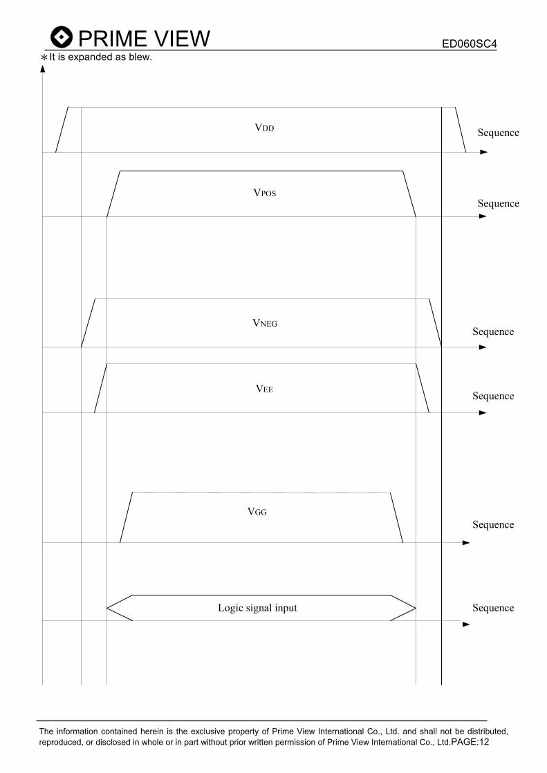
7.Power on Sequence 1. VSS � VDD � VNEG � VPOS (Source driver) 2. VEE � VGG(Gate driver)
VSS
VDD
VPOS
VGG
VEE
VNEG
Logic signal input
T1:100 µs(min)
T2: 0 µs(min)
T3: 1000 µs (min)
T6 T7
T4: 0 µs (min)
T5: 0 µs (min)
T6: 0 µs (min)
T7: 0 µs (min)
T1 T2 T3 T4T5
ED060SC4
The information contained herein is the exclusive property of Prime View International Co., Ltd. and shall not be distributed,
reproduced, or disclosed in whole or in part without prior written permission of Prime View International Co., Ltd.PAGE:12
*It is expanded as blew.
VDD
VPOS
VNEG
VEE
VGG
Logic signal input
Sequence
Sequence
Sequence
Sequence
Sequence
Sequence

ED060SC4
The information contained herein is the exclusive property of Prime View International Co., Ltd. and shall not be distributed,
reproduced, or disclosed in whole or in part without prior written permission of Prime View International Co., Ltd.PAGE:13
8. Optical characteristics
8-1)Specifications
Measurements are made with that the illumination is under an angle of 30 degrees, the detection is
perpendicular unless otherwise specified.
T = 25oC
SYMBOL PARAMETER CONDITIONS MIN TYP. MAX UNIT Note
R Reflectance White 30 35 - % -
Gn Nth Grey Level - - DS+(WS-DS)×n/(m-1) - L* -
CR Contrast Ratio - 6 - - -
Tupdate Update time 2~4-bit mode
1-bit mode 1000
540 -
ms
ms -
WS: White state , DS: Dark state, Gray state from Dark to White :DS、G1、G2…、Gn…、Gm-2、WS
m:4、8、16 when 2、3、4 bits mode
8-2)Definition of contrast ratio
The contrast ratio (CR) is the ratio between the reflectance in a full white area (Rl) and the reflectance in a
dark area (Rd):
CR = Rl/Rd

ED060SC4
The information contained herein is the exclusive property of Prime View International Co., Ltd. and shall not be distributed,
reproduced, or disclosed in whole or in part without prior written permission of Prime View International Co., Ltd.PAGE:14
8-3)Reflection Ratio
The reflection ratio is expressed as:
R = Reflectance Factorwhite board x ( Lcenter / Lwhite board )
Lcenter is the luminance measured at center in a white area (R=G=B=1). Lwhite board is the luminance of a
standard white board. Both are measured with equivalent illumination source. The viewing angle shall be
no more than 2 degrees.
α = declination / θ = azimuth
8-4)Waveform
- Wave Form file should be available before panel delivery to customer.
- Wave Form file size should be 64Kb
- Ghosting quality is measured by the reflectance difference between specific area and surface. In MU and GU mode, within 3L* In GC mode, within 2L*

ED060SC4
The information contained herein is the exclusive property of Prime View International Co., Ltd. and shall not be distributed,
reproduced, or disclosed in whole or in part without prior written permission of Prime View International Co., Ltd.PAGE:15
9.HANDLING, SAFETY AND ENVIROMENTAL REQUIREMENTS
WARNING
The display glass may break when it is dropped or bumped on a hard surface. Handle with care. Should
the display break, do not touch the electrophoretic material. In case of contact with electrophoretic
material, wash with water and soap.
CAUTION
The display module should not be exposed to harmful gases, such as acid and alkali gases, which corrode
electronics components.
Disassembling the display module can cause permanent damage and invalidates the warranty agreements.
Observe general precautions that are common to handling delicate electronic components. The glass can
break and front surfaces can easily be damaged. Moreover the display is sensitive to static electricity and
other rough environmental conditions.
Data sheet status
Product
specification
This data sheet contains final product specifications.
Limiting values
Limiting values given are in accordance with the Absolute Maximum Rating System (IEC
134). Stress above one or more of the limiting values may cause permanent damage to the
device. These are stress ratings only and operation of the device at these or at any other
conditions above those given in the Characteristics sections of the specification is not implied.
Exposure to limiting values for extended periods may affect device reliability.
Application information
Where application information is given, it is advisory and does not form part of the
specification.

ED060SC4
The information contained herein is the exclusive property of Prime View International Co., Ltd. and shall not be distributed,
reproduced, or disclosed in whole or in part without prior written permission of Prime View International Co., Ltd.PAGE:16
10. Reliability test TEST CONDITION METHOD REMARK
1 High-Temperature
Operation
T = +50°C, RH = 30% for
240 hrs
IEC 60
068-2-2Bp
At the end of the test, electric,
mechanical, and optical
specifications shall be satisfied.
2 Low-Temperature
Operation T = 0°C for 240 hrs
IEC 60
068-2-2Ab
At the end of the test, electric,
mechanical, and optical
specifications shall be satisfied.
3 High-Temperature
Functional
T = +60°C, RH=26% for 240
hrs
IEC 60
068-2-2Bp
At the end of the test, electric,
mechanical, specifications shall
be satisfied.
4 Low-Temperature
Functional T = -10°C for 240 hrs
IEC 60
068-2-2Ab
At the end of the test, electric,
mechanical, specifications shall
be satisfied.
5 High-Temperature
Storage
T = +70°C, RH=23% for 240
hrs
IEC 60
068-2-2Bp
At the end of the test, electric,
mechanical, and optical
specifications shall be satisfied.
6 Low-Temperature
Storage T = -25°C for 240 hrs
IEC 60
068-2-1Ab
At the end of the test, electric,
mechanical, and optical
specifications shall be satisfied.
7
High-Temperature,
High-Humidity
Operation
T = +40°C, RH = 90% for
168 hrs
IEC 60
068-2-3CA
At the end of the test, electric,
mechanical, specifications shall
be satisfied.
8
High Temperature,
High- Humidity
Storage
T = +60℃, RH=80% for
240hrs
IEC 60
068-2-3CA
At the end of the test, electric,
mechanical, specifications shall
be satisfied.
9 Temperature Cycle 1 cycle:[-25℃ 30min]→[+70
℃ 30 min] : 100 cycles
IEC 60
068-2-14
At the end of the test, electric,
mechanical, specifications shall
be satisfied.
10 UV exposure
Resistance 765 W/m
2 for 168hrs,40℃
IEC60
068-2-5Sa
Optical characteristics shall be
satisfied.
11 Package Vibration
1.04G, Frequency:
10~500Hz
Direction: X,Y,Z
Duration: 1 hours in each
direction
Full packed
for shipment
At the end of the test, electric,
mechanical, and optical
specifications shall be satisfied.
12 Package Drop
Impact
Drop from height of 122 cm
on concrete surface.
Drop sequence: 1 corner, 3
edges, 6 faces
One drop for each.
full packed for
shipment
At the end of the test, electric,
mechanical, and optical
specifications shall be satisfied.
13 Electrostatic Effect
(non-operating)
Machine model
+/- 250V, 0Ω, 200pF
IEC 62179,
IEC 62180
At the end of the test, electric,
mechanical, specifications shall
be satisfied.
14 Altitude test
Operation
700hPa ( = 3000m )
48Hr
At the end of the test, electric,
mechanical, specifications shall
be satisfied.

ED060SC4
The information contained herein is the exclusive property of Prime View International Co., Ltd. and shall not be distributed,
reproduced, or disclosed in whole or in part without prior written permission of Prime View International Co., Ltd.PAGE:17
15 Altitude test
Storage
260hPa ( = 10000m )
48Hr
At the end of the test, electric,
mechanical, specifications shall
be satisfied.
16 Stylus Tapping
POLYACETAL Pen: Top
R:0.4mm
Load: 300gf
Speed: 5times/sec
Total 13,500times,
Test should be
done with a
bezel
Pass criteria – no glass
breakage or damage to
microcapsules.
Actual EMC level to be measured on customer application
11. Bar Code definition
E0R 00 4 01 1 I 7 4 00361 A T
1 2 3 4 2 5 6 2 7 2 8
1 :EPD model code:
ED060SC4:E0R
2 :Internal control codes:
3 :FPL reversion code
V110:4
4 :FPL batch code:
(BL/P/B...)001~009:01~99, 100~109:A0~A9, 110-119:B0~B9… 320~329:Z0~Z9
5 :Year:
F:2005 / G:2006 / H:2007 / I:2008 /... / Z:2025
6 :Month:
1:Jan. 2:Feb. ... 9:Sep. A:Oct. B:Nov. C:Dec.
7 :Serial number
8 :MFG code:
TOC:T, PVI:P

ED060SC4
The information contained herein is the exclusive property of Prime View International Co., Ltd. and shall not be distributed,
reproduced, or disclosed in whole or in part without prior written permission of Prime View International Co., Ltd.PAGE:18
12. Border definition
13.Block Diagram
Panel
H Driver(Source)
39 PIN Input
V Driver(Gate)

ED060SC4
The information contained herein is the exclusive property of Prime View International Co., Ltd. and shall not be distributed,
reproduced, or disclosed in whole or in part without prior written permission of Prime View International Co., Ltd.PAGE:19
14.Packing