technical specifications of hardware & accessories-acsr ...guvnl.com/tender/file/getco/corporate...
TRANSCRIPT

GETCO/ENGG/TECH. SPECI. –HARDWARE & ACCES ACSR PANTHER CONDUCTOR/REV-1 DT. 28.09.2007
Page 1 of 21
]
GUJARAT ENERGY TRANSMISSION
CORPORATION LTD. Sardar Patel Vidyut Bhavan, Race Course,
Vadodara: 390 007
TECHNICAL SPECIFICATIONS
OF
HARDWARE & ACCESSORIES-ACSR
PANTHER CONDUCTOR
FOR
TRANSMISSION LINE
GETCO/ENGG/TECH. SPECI. –HARDWARE & ACCES ACSR PANTHER
CONDUCTOR/REV-1 DT. 28/09.2007

GETCO/ENGG/TECH. SPECI. –HARDWARE & ACCES ACSR PANTHER CONDUCTOR/REV-1 DT. 28.09.2007
Page 2 of 21
]
SPECIAL INSTRUCTIONS TO BIDDER
Please read following instructions carefully before submitting your bid.
1. All the drawings, i.e. elevation, side view, plan, cross sectional view etc., in AutoCAD
format and manuals in PDF format, for offered item shall be submitted. Also the hard copies as per specification shall be submitted.
2. The bidder shall submit Quality Assurance Plan for manufacturing process and Field
Quality Plan with the technical bid. 3. The bidder shall have to submit all the required type test reports for the offered item. In
case of non-submission of type test reports, the evaluation shall be carried out accordingly as non-submission of Type Tests Reports.
4. The bidder must fill up all the point of GTP for offered item/s. Instead of indicating “refer
drawing, or as per IS/IEC”, the exact value/s must be filled in. 5. All the points other than GTP, which are asked to confirm in technical specifications must
be submitted separately with the bid. 6. The bidder is required to impart training in view of manufacture, assembly, erection,
operation and maintenance for offered item, at his works, to the person/s identified by GETCO, in the event of an order, free of cost. The cost of logistics will be borne by GETCO.
7. Please note that the evaluation will be carried out on the strength of content of bid only.
No further correspondence will be made.
8. The bidder shall bring out all the technical deviation/s only at the specified annexure.
9. The bidder should indicate manufacturing capacity by submitting latest updated certificate of a Chartered Engineer (CE).

GETCO/ENGG/TECH. SPECI. –HARDWARE & ACCES ACSR PANTHER CONDUCTOR/REV-1 DT. 28.09.2007
Page 3 of 21
]
QUALIFYING REQUIREMENT DATA (For Supply)
Bidder to satisfy the following requirements.
1) The bidder shall be Original Equipment Manufacturer (OEM). The offered
equipment have to be designed, manufactured and tested as per relevant IS/IEC with latest amendments.
2) The minimum requirement of manufacturing capacity of offered type, size and rating of equipment shall be 7 times tender / bid quantity. The bidder should indicate manufacturing capacity by submitting latest updated certificate of a Chartered Engineer (CE).
3) Equipment proposed shall be of similar or higher rating and in service for a minimum period of THREE (3) years and satisfactory performance certificate in respect of this is to be available and submitted.
4) The bidder should clearly indicate the quantity and Single Value Contract executed during last FIVE (5) years, for the offered equipment. Bidder should have executed one single contract during last five years for the quantity equivalent to tender / bid.
The details are to be submitted in following format,
Sr. No
ITEMS SUPPLIED
TO
ORDER REFERENCE No. & DATE
ITEMS QUANTITY ORDER FULLY
EXECUTED. YES/NO
STATUS, IF ORDER UNDER
EXECUTION
REMARK
5) Equipment offered shall have Type Test Certificates from accredited laboratory (accredited based on ISO/IEC Guide 25 / 17025 or EN 45001 by the National accredition body of the country where laboratory is located), as per IEC / IS / technical specification. The Type test reports shall not be older than FIVE years and shall be valid upto the expiry of validity of offer.

GETCO/ENGG/TECH. SPECI. –HARDWARE & ACCES ACSR PANTHER CONDUCTOR/REV-1 DT. 28.09.2007
Page 4 of 21
]
SECTION: HARDWARE-I
GENERAL TECHNICAL REQUIREMENTS FOR INSULATOR HARDWARE FOR 132 KV TRANSMISSION LINES
1.1 Scope: 1.1.1 This section of specification covers design, manufacture, testing at manufacturer’s
work before dispatch, supply and delivery of complete suspension and tension insulator hardware for power conductor for transmission lines.
1.2 Standards: 1.2.1 The hardware shall comply in all respect with the provisions of IS: 2486, Part-I, II and
III/ 1974 with latest amendment for insulator fittings.
1.3 Particulars of the Power System: 1.3.1 The particulars of power system, in which the hardware required to be used, are given
in section–II of this specification.
1.4 Material and design: 1.4.1 The materials offered shall be of first class quality, workmanship, well finished and of
approved design. All castings shall be free from blow holes, flaws, cracks or other defects and shall be smooth, close, grained and of true forms and dimensions.
1.4.2 The Ball & Socket designation must be 16 mm for Suspension & 20mm for Tension clamps
1.4.3 Minimum thickness of the any portion of the forged steel part shall be not less than 10 mm.
1.5 Insulator hardware:
1.5.1 Suspension and Tension Clamps: 1.5.1.1 The clamps offered should be light in weight free from corona formation, high
corrosion resistant and shall have low power loss. The design, finish and shape of the clamps be such as to avoid all hot spots, kinks, cuts, grooves and projections which may injure the conductor, insulator or fittings or lead to localized pressure. The clamps, body and keeper pieces (wherever required) shall be made of high strength cast aluminum alloys, while cotter pins, cotter bolts, ‘U’ bolts, eye hooks, twisted shackles, ball eyes and clevis, chain links etc. shall be made of forged high carbon steel hot dip galvanized. Split pins of minimum 4 mm, diameter and suitable strength, made of brass shall be used. The security clips shall be ‘R’ type made of phosphor bronze and 7 mm width.
1.5.1.2 The suspension clamp shall be of Forged Steel hanger and free center type. The
clamps shall have sufficient contact surface to minimum damage due to fault currents. The clamps shall be suitable for use with conductor indicated in Section-II, when wrapped with formed Armour rods. The clamps shall permit the conductor to slip, before failure of the conductor occurs and shall have a sufficient slipping strength to resist conductor tension under broken wire conditions. The slipping strength and the minimum failing loads of the clamps shall not be less than specified in Section-II of this specification. All bolts and ‘U’ bolts shall be provided with check nuts.

GETCO/ENGG/TECH. SPECI. –HARDWARE & ACCES ACSR PANTHER CONDUCTOR/REV-1 DT. 28.09.2007
Page 5 of 21
]
1.5.1.3 The tension clamps shall be of the compression type ACSR ‘PANTHER’ conductor. The tension clamp shall permit slipping or damage or failure of the conductor at a load less than 95% of the ultimate strength of the conductor. The mechanical efficiency of the tension clamp shall not be affected by any method of erection. The aluminium sleeve shall be made from extruded aluminium tube with purity of aluminium not less than 99.5%. The steel sleeve shall be made from steel tube of high strength steel. The clamps shall be provided with adequate bolts and nuts as well as check nuts for rigid connection and to avoid the jumper connection becoming loose during service.
1.5.2 Arcing Horns for Suspension and Tension Clamp: 1.5.2.1 Each hardware assembly shall be provided with arcing horns on the line side of
suspension and tension strings. 1.5.2.2 In the approach spans, upto a distance of 1.6 km from the sub-station adjustable
arcing horns on line and tower end sides shall be provided with suitable gap, so as to give better insulation co-ordination and ensure effective operations under actual conditions. The range setting of arcing horns should be given in the bid.
1.6 Galvanization: 1.6.1 All ferrous parts of insulator hardware of power conductors shall be galvanized in
accordance with IS: 2629/19132 (with latest amendment) ‘Recommended practice for hot dip galvanizing of Iron and Steel’. The method for testing weight, thickness and uniformity of coating of hot dip galvanized articles shall be in accordance with IS: 2633/1972 (with latest amendment). The hardware shall have Zinc coating of 610 gm/m
2.
1.6.2 The Zinc used for galvanizing shall conform to grade Zn of IS: 209 - Relevant extract
from IS: 209 (with latest amendment). 1.6.3 The threads in nuts and tapped holes shall be cut after galvanizing and shall be well
lubricated or greased. All other threads shall be cut before galvanizing. The bolt threads shall be under cut to take care of increase in diameter due to galvanizing.
1.6.4 Spring washers shall be electro-galvanized.
1.7 Inspection of lot offered: 1.7.1 The firm may offer the lot of hardware for inspection at his works prior to dispatch.
The minimum lot size shall be 100 Nos. or the full quantity of the order, whichever is less. The firm shall give minimum 15 days advance notice to the purchaser to enable the purchaser to depute his representative for witnessing the Acceptance Tests.
1.7.2 Depending upon the lot size offered, number of samples may be selected randomly
as per Appendix–A of IS under reference. 1.7.3 On each selected sample, all the acceptance tests mentioned in clause No. 1.7.4
shall be carried out in accordance with the provisions of IS:2486 (Part-I/1971) with latest amendments and GETCO specifications.
1.7.4 Acceptance Tests:
The following acceptance tests may be carried out:
(a) Visual examination (b) Dimensional check

GETCO/ENGG/TECH. SPECI. –HARDWARE & ACCES ACSR PANTHER CONDUCTOR/REV-1 DT. 28.09.2007
Page 6 of 21
]
(c) Galvanizing test (d) Mechanical test for clamps and fittings (e) Electrical resistance test (Only for Tension clamps) (f) Slip strength test
1.7.5 The above acceptance tests are to be carried out either at the firm’s works or at Govt.
Approved laboratory (in case of adequate testing facilities are not available at the firm’s works) in the presence of inspector deputed by the GETCO. However, all the testing charges for such testing shall be borne by the firm only.
1.7.6 Unless the acceptance tests are successfully completed and the GETCO or waiver of
inspection thereof issues approval is obtained in writing from GETCO by the firm; the firm shall not dispatch any material to GETCO.
1.7.7 Routine Tests: The firm for the following routine tests shall test 1.7.7.1 All the hardwares offered in the lot:
(i) Visual examination test (ii) Routine mechanical test
1.7.7.2 The firm may keep ready the certificates of routine tests for handing over the same to the
inspector deputed during inspection of lot.
1.8 Hot Line Maintenance: 1.8.1 The hardware fittings, offered shall be suitable for employing hot line maintenance
techniques, with requisite speed, ease and safety.
1.9 Submission of Drawings and Type Test certificates: 1.9.1 The tenderer shall submit full detailed dimensional drawings indicating the materials
of each part and test certificates thereof for the materials composition for the items of hardwares offered. In absence of the same, the offer shall be out rightly ignored. The approved drawings set must be submitted in soft copy in Auto CAD format. Vacant .
1.9.2 The tenderer shall submit with Technical Bid the type tests certificates (along with
certified copy of dimensional drawing of hardware tested) for the entire type test as stated below issued by independent Govt. approved laboratories.
1.9.2.1 Type tests for clamps
a) Visual examination b) Verification of dimensions c) Slip strength tests d) Ultimate strength tests e) Electrical resistance test (for tension clamps only) f) Heating cycle test (for tension clamps only) g) Galvanizing / electroplating tests
1.9.2.2 Type tests on insulator string fittings except clamps
a) Visual examination b) Verification of dimensions c) Mechanical tests d) Galvanizing tests e) Chemical composition test
1.9.2.3 Type tests on non-tension components

GETCO/ENGG/TECH. SPECI. –HARDWARE & ACCES ACSR PANTHER CONDUCTOR/REV-1 DT. 28.09.2007
Page 7 of 21
]
a) Visual examination b) Verification of dimensions c) Mechanical tests 1.9.2.4 In case of non-submission of type test reports; the evaluation shall be carried out
accordingly. 1.9.2.5 The purchaser reserves the right to ask the supplier to arrange type tests on samples
selected from any of offered lot for inspection in presence of GETCO representative. The testing charges for the same shall be borne by the GETCO if the sample
withstands the tests successfully otherwise tenderer have to bear the same.
1.9.2.6 QUALITY ASSURANCE PLAN
The bidder shall invariably furnish following information along with his offer, failing
which his offer shall be rejected. i) Statement giving list of important raw materials names of sub suppliers for the raw
materials, list of standards according to which the raw materials are tested, list of tests normally carried out on raw materials in presence of supplier's representative and as routine and / or acceptance during production and on finished goods, copies of test certificates.
ii) Information and copies of test certificates as in (i) above in respect of bought out
accessories. iii) List of manufacturing facilities available. iv) Level of automation achieved and lists of areas where manual processing exists. v) List of areas in manufacturing process, where stage inspections are normally carried
out for quality control and details of such tests and inspections. vi) List of testing equipment available with the Supplier for final testing. vii) The GETCO reserves the right for factory inspection to verify the facts quoted in the
offer. If any of the facts are found misleading or incorrect the offer of that Bidder will be out rightly rejected and he may be black listed.
viii) Special features provided to make it maintenance free. 1.10 Interchangeability: 1.10.1 Corresponding parts of hardwares should be made to gauge or jig and shall be
interchangeable in every respect.
1.11 Marking: 1.11.1 The item shall be legibly and indelibly marked with following details on each of main
component of hardware.
(a) Name or Trademark of the manufacturer (b) ‘GETCO’
1.11.2 The packages containing fittings may also be marked with ISI certificates and mark.
1.12 Packing:

GETCO/ENGG/TECH. SPECI. –HARDWARE & ACCES ACSR PANTHER CONDUCTOR/REV-1 DT. 28.09.2007
Page 8 of 21
]
1.12.1 All hardware and accessories shall be supplied in strong wooden boxes/ crates with steel hoop and hands to withstand rough handling during the transits and transportation.
However, the Stores may be packed in double gunny bags with proper packing filters if delivered by road transport on door delivery basis. The gross weight of wooden packing shall not normally exceed 500 Kg. Different fittings with the accessories shall be packed in different packing. All nuts should be hand tightened to the maximum possible point.
1.12.2 All parts shall be adequately and clearly marked for safe delivery and proper
identification at destination.
1.13 Guaranteed Technical Particulars (GTP): 1.13.1 The tenderer shall fill in the guaranteed technical particulars of accessories given in
Schedule–A, Section–III of this specification. All the columns must be filled in clearly. Tenders incomplete in this respect shall be out rightly ignored.
1.14 ISI Mark:
1.14.1 Materials having ISI mark shall be preferable.
1.15 Note to the Bidders: 1.15.1 The purchaser reserves the right to award contract item-wise basis or to reject the
offer without assigning any reasons. 1.15.2 The offers without samples will be out rightly rejected. The samples submitted shall
not be returned back. If desired, the GETCO will carry the testing of sample at GETCO’s cost as per relevant IS before accepting the offer.

GETCO/ENGG/TECH. SPECI. –HARDWARE & ACCES ACSR PANTHER CONDUCTOR/REV-1 DT. 28.09.2007
Page 9 of 21
]
SECTION: HARDWARE-II
SPECIFIC TECHNICAL REQUIREMENT
2.1 Scope: 2.1.1 This section covers the specific technical particulars, requirement and desired delivery
etc. for the insulator hardware for 132 KV transmission line. The equipment shall also conform to the general technical requirements covered under section-I of this specification.
2.2 System and Climatic Particulars:
(i) Line voltage: 132 KV (ii) Frequency: 50 c/s (iii) No. Of Circuits: Single Circuit and Double Circuit (iv) Tower configuration: Barrel type (v) Normal Span: 320 Mts. (vi) Wind Pressure on: 150 kg/m
2 on 2/3
rd projected area
Conductor and Earth Wire (vii) Temperature Range:
(a) Minimum: 00 C
(b) Maximum: 670 C
(c) Everyday: 320 C
2.3 Technical Particulars:
2.3.1 Conductor: (i) Type: ACSR ‘PANTHER’ (ii) Stranding & Wire Dia.:
(a) Aluminum: 30/3 mm (b) Steel: 7/3 mm
(iii) Overall Diameter: 21 mm (iv) Approximate Total: 976 Kg/km. Weight (v) Ultimate Strength: 9100 Kg.
2.3.2 Insulators hardware: (Ref. Drg. No.ENGG/ACSR/SS-PANTHER/05, ENGG/ACSR/ST- PANTHER /06, ENGG/ACSR/DS- PANTHER /07 & ENGG/ACSR/DT- PANTHER / 08) (i) Slipping Strength:
(a) Suspension Clamps: 15% of ultimate strength of conductor i.e.1365 Kg (b) Tension Clamps: 95% of ultimate strength of conductors i.e. 8645 Kg
(ii) Minimum Failing Load: ‘PANTHER’ (a) Suspension Fittings: 4600 Kg. (b) Tension Fittings: 100% of UTS of conductor i.e. 9100 Kg.
(iii) Type: (a) Suspension Clamps: Forged Steel hanger type free centered type
without bolt only (b) Tension Clamp: Compression type
(iv) Material: As stated in Drawings Nos. given in Cl.No. 2.3.2
above
GETCO/ENGG/TECH. SPECI. –HARDWARE & ACCES ACSR PANTHER CONDUCTOR/REV-1 DT. 28.09.2007
Page 10 of 21
]
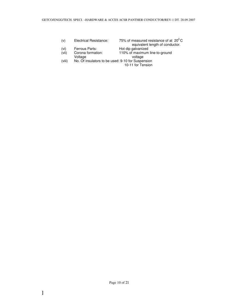
(v) Electrical Resistance: 75% of measured resistance of at 200 C
equivalent length of conductor. (vi) Ferrous Parts: Hot dip galvanized (vii) Corona formation: 110% of maximum line-to-ground
Voltage voltage (viii) No. Of insulators to be used: 9-10 for Suspension 10-11 for Tension

GETCO/ENGG/TECH. SPECI. –HARDWARE & ACCES ACSR PANTHER CONDUCTOR/REV-1 DT. 28.09.2007
Page 11 of 21
]
SECTION-III
BIDDING SCHEDULES (To be filled in and signed by Tenderer)
SCHEDULE – A
Hardware: (i) Item/Part
1) Ball hook 2) Socket eye 3) Arcing horn on line side 4) Arcing horn on tower side (fixed or adjustable) 5) Suspension clamp 6) Tension clamp 7) Eye hook 8) Clevis 9) Yoke 10) Ball clevis 11) Socket clevis 12) Clevis eye 13) Horn holder ball hook 14) Anchor shackle 15) Ball link 16) Horn holder ball link 17) Twisted shackle 18) Chain link 19) ‘R’ type security clip and split pin
(ii) 1) Minimum failing load 2) Weight 3) Slipping strength
(iii) Angle of inclination of clamp to Jumper terminal (iv) Electrical conductivity of clamp
(a) Results of heating cycle test carried out (b) Value of electrical resistance
(v) Power loss of clamps (vi) Make of bolts and nuts used (vii) Standard specification to which galvanizing conforming.
Signature of the Bidder: __________
Name: _______________________
Designation: ___________________ Date: _____________
Authorized common rubber
Stamp / seal of the bidder: _________

GETCO/ENGG/TECH. SPECI. –HARDWARE & ACCES ACSR PANTHER CONDUCTOR/REV-1 DT. 28.09.2007
Page 12 of 21
]
SECTION: ACCESSORIES -I
GENERAL TECHNICAL REQUIREMENTS FOR POWER CONDUCTOR ACCESSORIES FOR 132 KV TRANSMISSION LINES
1.1 Scope: 1.1.1 This section of specification covers design, manufacture, testing at manufacturer’s
works before dispatch, supply and delivery of complete accessories for power conductor for transmission lines.
1.2 Standards: 1.2.1 The accessories for ACSR conductor for overhead line with the provisions of ISS:
2121/1981 and IS: 9708/1980 (with latest amendment, if any).
1.3 Particulars of the Power System: 1.3.1 The particulars of power system, in which the accessories are required to be used,
are given in section–II of this specification.
1.4 Materials and Design: 1.4.1 The material offered should be of first class quality, workmanship, well finished and of
approved design. All castings shall be free from blow holes, flows, cracks or other defects and shall be smooth, close, grained and of true forms and dimensions.
1.5 Accessories for Power Conductors:
1.5.1 Compression type Mid–span Straight Joints: 1.5.1.1 Compression type mid-span straight joints offered shall be suitable for making joints
in the ACSR conductor, details of which are given in Section-II of this specification. The joints offered should conform to IS:2121/1981 (with latest amendment).
1.5.1.2 the joint shall be so designed, that when installed, no air space is left within the
finished joint. The joint shall have conductivity as specified but the mechanical strength shall not be less than 95% of the ultimate tensile strength of the conductor.
1.5.1.3 The aluminum sleeve shall be made from extruded aluminum tube of aluminum of
purity not less than 99.5%. The steel sleeve shall be of high strength steel.
1.5.2 Repair Sleeve: 1.5.2.1 Compression type repair sleeves shall be offered to provide reinforcement of
conductor with broken or damaged aluminum strands. The repair sleeves shall be designed to make good a conductor, of which not more than 1/6
th of the strands, in
the outermost layer, are damaged or severed. The repair sleeves after compression should present a smooth surface. The repair sleeves offered should conform to IS: 2121/1981 (with latest amendment).
1.5.3 Preformed Armour Rods: 1.5.3.1 Helically – twisted formed Armour rods offered, shall be suitably for ACSR power
conductor, the details of which are given in Section-II of this specification, to provide

GETCO/ENGG/TECH. SPECI. –HARDWARE & ACCES ACSR PANTHER CONDUCTOR/REV-1 DT. 28.09.2007
Page 13 of 21
]
rigidity and protection into the conductor at all suspension points, as also to eliminate the fatigue on the conductor due to vibration.
1.5.3.2 Armour rods shall be made of aluminum alloys, the Armour rods shall be marked in
the center, to facilitate its identification and application on conductor. No joint shall be permitted in the rods, except those made in base rods before drawing.
1.5.3.3 The preformed Armour rods shall be capable of being fixed by hand on the conductor,
without the aid of any tools or implements. The direction of spiral shall be same as that of conductor. The wire of the outermost layer of aluminum strands of the conductor shall have right-hand lay. The loading stress of Armour rods on the conductor shall be evenly distributed over the entire length and there shall be no tendency of loosening at the ends. The preformed Armour rods shall not loose their resilience, even after two or three applications. The rods should be capable of providing high self-retaining strength and protection against vibration, damage, fatigue and failure of conductor. The ends should be properly ball ended so that the danger of corona formation is avoided.
1.5.3.4 The surface of the Armour rods when fitted on the conductor shall be smooth and free
from projections, cuts and abrasions etc.
1.5.4 4R Vibration Dampers: 1.5.4.1 4R type vibration dampers are proposed to be provided in each span, one at each end
of conductor with normal span 320 mt. for 132 KV lines. The dampers shall be capable of effectively damping out the vibration of the conductors. In longer spans two dampers are proposed to be fitted on each end of conductor.
1.5.4.2 Calculations and complete design, weight etc. of the damper shall be furnished with
the tender together with the damping characteristics and energy dissipation curves of the dampers and guarantee of their effectiveness for the conductor specified. For purpose of this calculations, the designed data shall be as given in Section-II of this specification. The offer is liable for rejection in the absence of this data.
1.5.4.3 The vibration dampers shall be of approved design. The clamp of the vibration
damper shall be made of aluminum alloy so designed as to prevent any damage to or chafing of the conductor, during erection or continued operation.
1.5.4.4 Clamping bolts shall be provided with self-locking nuts designed to prevent corrosion
of the threads. All ferrous parts, including the messenger cable shall be hot dip galvanized. The ends of the messenger cable shall be effectively sealed to prevent corrosion.
1.6 Galvanization: 1.6.1 All ferrous parts of accessories for power conductors shall be galvanized in
accordance with IS: 2629-1966 (with latest amendment) ‘Recommended practice for hot dip galvanizing of Iron and Steel’. The method for testing weight, thickness and uniformity of coating of hot dip galvanized articles shall be in accordance with IS: 2633-1972 (with latest amendment). The hardware and accessories shall have Zinc coating of 610 gm/m
2.
1.6.2 The Zinc used for galvanizing shall conform to grade Zn of IS: 209 - relevant extract
from IS: 209.

GETCO/ENGG/TECH. SPECI. –HARDWARE & ACCES ACSR PANTHER CONDUCTOR/REV-1 DT. 28.09.2007
Page 14 of 21
]
1.6.3 The threads in nuts and tapped holes shall be cut after galvanizing and shall be of well lubricated or greased. All other threads shall be cut before galvanizing. The bolt threads shall be under cut to take care of increase in diameter due to galvanizing.
1.6.4 Spring washers shall be electro-galvanized.
1.7 Tests:
1.7.1 Type Tests: The tenderer shall submit with Technical Bid the type tests certificates (along with
certified copy of dimensional drawing of accessories tested) for all the type tests as stated below issued by independent government approved laboratory.
1.7.1.1 Preformed Armour Rod a) Visual examination. b) Verification of dimension c) Tensile strength test d) Electrical resistance test. e) Slip strength test. f) Bend test g) Resilient test
1.7.1.2 Mid Span Joint & Repair Sleeve a) Visual examination. b) Verification of dimension c) Failing load test d) Electrical resistance test. e) Heating cycle test. f) Galvanizing test
1.7.1.3 Vibration Damper a) Visual examination. b) Verification of dimension c) Resonance frequency test d) Fatigue test. e) Mass pull off test. f) Dynamic characteristics test g) Damping efficiency test h) Clamp slip test i) Torque test j) Galvanizing / Electroplating test k) Magnetic power loss test
In case of non-submission of type test reports, the evaluation shall be carried out accordingly.
The purchaser reserves the right to ask the supplier to arrange type tests on samples selected from any of offered lot for inspection in presence of GETCO representative.
The testing charges for the same shall be borne by the GETCO if the sample withstands the tests successfully otherwise tenderer have to bear the same.
1.7.2 Acceptance of Lot: 1.7.2.1 The firm may offer a lot of 100 nos. of the items or ordered quantity, whichever is less
for inspection. The firm may give minimum 15 days advance notice to the purchaser

GETCO/ENGG/TECH. SPECI. –HARDWARE & ACCES ACSR PANTHER CONDUCTOR/REV-1 DT. 28.09.2007
Page 15 of 21
]
so as to facilitate the purchaser to depute his representative for witnessing the acceptance tests at the firm’s works.
1.7.2.2 All the acceptance tests mentioned in subsequent clause No. 1.7.2.4 shall be carried
out by the firm at his works in the presence of GETCO’s representative on the samples selected as per the sampling criteria of relevant IS. Incase the testing facilities are not available at the firm’s works, and then the firm has to arrange for the same at govt. approved laboratory. However, such testing charges shall be borne by the firm only.
1.7.2.3 Unless the materials are inspected and all acceptance tests are completed
satisfactorily and approval thereof is given in writing, the materials shall not be dispatched by the supplier.
1.7.2.4 Acceptance Tests:
1.7.2.4.1 Acceptance Tests of Repair Sleeves & Mid Span Joint
The following acceptance tests shall be carried out on Repair sleeves as per IS: 2121 (part-II)/ 1981 (with latest amendment).
(i) Visual examination (ii) Dimensional verification (iii) Failing load test (iv) Galvanizing test (v) Electrical resistance test
1.7.2.4.2 Acceptance Tests for P. A. Rods:
The following acceptance tests shall be carried out on P.A. rods as per IS: 2121 (part-I)/1981 (with latest amendment).
(i) Visual examination (ii) Verification of dimension (iii) Tensile strength test (iv) Electrical resistance test (v) Slip strength test
1.7.2.4.3 Acceptance Tests for Vibration Dampers:
The following acceptance tests shall be carried out on vibration dampers as per IS: 9708/ 1980 (with latest amendment).
(i) Visual examination (ii) Verification of dimensions (iii) Resonance frequency test (iv) Fatigue test (v) Mass pull off test (vi) Galvanizing test
1.7.3 Submission of Routine Test Certificates:
The firm has to carry out specified routine tests on all the items offered by him in the lot and submits the certificates thereof to the Inspector deputed by GETCO at the time of inspection of lot.
1.8 Hot Line Maintenance:

GETCO/ENGG/TECH. SPECI. –HARDWARE & ACCES ACSR PANTHER CONDUCTOR/REV-1 DT. 28.09.2007
Page 16 of 21
]
1.8.1 The accessories for power conductor offered shall be suitable for employing line
maintenance techniques, with requisite speed, ease and safety.
1.9 Drawings: 1.9.1 The tenderer shall submit full detailed dimensional drawings to scale indicating the
materials used for the construction of each part along with the test certificates for the materials. The offer will be liable to be rejected if the drawings along with materials composition certificates are not submitted along with the offer. The approved drawings set must be submitted in soft copy in Auto CAD format.
1.10 Interchangeability: 1.10.1 Corresponding parts of power conductor accessories should be made to gauge or jig
and shall be interchangeable in every respect.
1.11 Marking: 1.11.1 Each item to be supplied shall be legibly and indelibly marked with trademark of the
manufacturer and suitable identification mark along with the word ‘GETCO’.
1.12 Packing: 1.12.1 All hardware and accessories shall be supplied in strong wooden boxes/ crates with
steel hoop and hands to withstand rough handling during the transits and transportation.
However, the Stores may be packed in double gunny bags with proper packing filters if delivered by road transport on door delivery basis. The gross weight of wooden packing shall not normally exceed 500 Kg. Different fittings with the accessories shall be packed in different packing. All nuts should be hand tightened to the maximum possible point.
1.12.2 All parts shall be adequately and clearly marked for safe delivery and proper
identification at destination.
1.13 Guaranteed Technical Particulars (GTP): 1.13.1 The tenderer shall fill in the guaranteed technical particulars of accessories given in
Schedule–A, Section–III of this specification. All the columns must be filled in clearly. Tenders incomplete in this respect shall be out rightly ignored.
1.14 ISI Mark: 1.14.1 Materials having ISI mark shall be preferable.
GETCO/ENGG/TECH. SPECI. –HARDWARE & ACCES ACSR PANTHER CONDUCTOR/REV-1 DT. 28.09.2007
Page 17 of 21
]
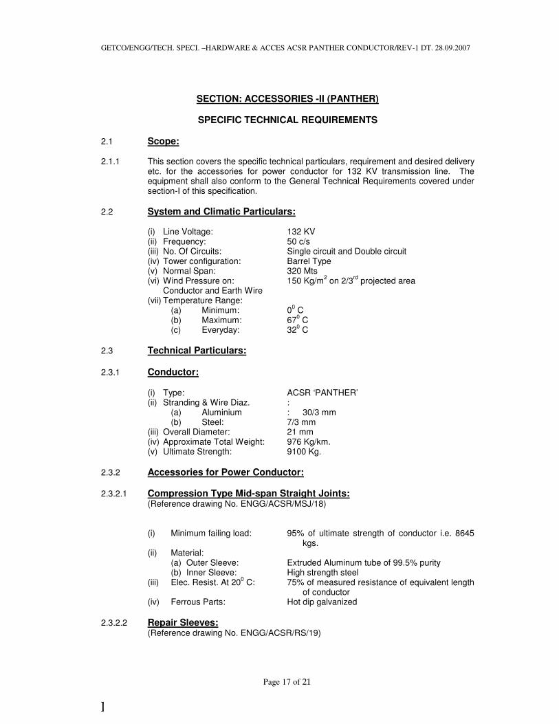
SECTION: ACCESSORIES -II (PANTHER)
SPECIFIC TECHNICAL REQUIREMENTS
2.1 Scope: 2.1.1 This section covers the specific technical particulars, requirement and desired delivery
etc. for the accessories for power conductor for 132 KV transmission line. The equipment shall also conform to the General Technical Requirements covered under section-I of this specification.
2.2 System and Climatic Particulars:
(i) Line Voltage: 132 KV (ii) Frequency: 50 c/s (iii) No. Of Circuits: Single circuit and Double circuit (iv) Tower configuration: Barrel Type (v) Normal Span: 320 Mts (vi) Wind Pressure on: 150 Kg/m
2 on 2/3
rd projected area
Conductor and Earth Wire (vii) Temperature Range:
(a) Minimum: 00 C
(b) Maximum: 670 C
(c) Everyday: 320 C
2.3 Technical Particulars:
2.3.1 Conductor:
(i) Type: ACSR ‘PANTHER’ (ii) Stranding & Wire Diaz. :
(a) Aluminium : 30/3 mm (b) Steel: 7/3 mm
(iii) Overall Diameter: 21 mm (iv) Approximate Total Weight: 976 Kg/km. (v) Ultimate Strength: 9100 Kg.
2.3.2 Accessories for Power Conductor:
2.3.2.1 Compression Type Mid-span Straight Joints: (Reference drawing No. ENGG/ACSR/MSJ/18)
(i) Minimum failing load: 95% of ultimate strength of conductor i.e. 8645 kgs.
(ii) Material: (a) Outer Sleeve: Extruded Aluminum tube of 99.5% purity (b) Inner Sleeve: High strength steel
(iii) Elec. Resist. At 200 C: 75% of measured resistance of equivalent length
of conductor (iv) Ferrous Parts: Hot dip galvanized
2.3.2.2 Repair Sleeves: (Reference drawing No. ENGG/ACSR/RS/19)

GETCO/ENGG/TECH. SPECI. –HARDWARE & ACCES ACSR PANTHER CONDUCTOR/REV-1 DT. 28.09.2007
Page 18 of 21
]
(i) Minimum failing load: 95% of ultimate strength of conductor i.e. 8645 kg.
(ii) Material: Aluminum alloy (iii) Elect. Resist. At 20
0 C: 75% of measured resistance of equivalent length
of conductor (iv) Corona formation: 110% of maximum line to ground Voltage voltage
2.3.2.3 Preformed Armour Rods: (Reference drawing No. ENGG/ACSR/PA ROD/17)
(i) Type: Preformed (ii) Material: Aluminum/Aluminum alloy (iii) Purity of Aluminum : EC Grade 99.5% (iv) Corona formation : 110% of maximum line to ground voltage (v) Conditions : Ball ended (vi) Direction of Lay of Rods : Right hand lay (vii) Consilic Strength: 35 kg. /mm
2
(viii) Slip Strength: 25% U.T.S. of conductor
2.3.2.4 Vibration Dampers: (Reference drawing No. ENGG/ACSR/VD/20)
(i) Type: 4R Type (ii) Material: Aluminum alloy/Steel (iii) Ferrous parts: Hot dip galvanized (iv) Testing as per: IS: 9708-1980 (with latest amendment)
IS specification?

GETCO/ENGG/TECH. SPECI. –HARDWARE & ACCES ACSR PANTHER CONDUCTOR/REV-1 DT. 28.09.2007
Page 19 of 21
]
SECTION-III
BIDDER SCHEDULE (To be filled in and signed by the Tenderer)
SCHEDULE – ‘A’
Accessories for Power Conductor: 132 KV
(i) Compression type Mid-span straight joints
1. Suitable for (conductor size): 2. Outside diameter of sleeves:
(a) Before compression: (i) Aluminum: (ii) Steel:
(b) After compression:
(i) Aluminum: (ii) Steel:
3) Length of Sleeve:
(a) Before compression: (i) Aluminum: (ii) Steel:
(b) After compression:
(i) Aluminum: (ii) Steel:
4) Weight of Sleeve:
(i) Aluminum kg. (ii) Steel kg. (iii) Total kg.
5) Slipping strength of mid-span joint:
6) Breaking strength of mid-span joint:
7) Conductivity of the compression joint:
8) Resistance as Percentage of Measured Resistance of Equivalent Length of Conductor:
(ii) Repair Sleeves:
1. Material: 2. Suitable for (conductor size): 3. Out side diameter of sleeves:
(a) Before compression: (b) After compression:
4. Length of sleeves: (a) Before compression: (b) After compression:
5. Weight of sleeve:

GETCO/ENGG/TECH. SPECI. –HARDWARE & ACCES ACSR PANTHER CONDUCTOR/REV-1 DT. 28.09.2007
Page 20 of 21
]
6. Breaking strength as percentage of: Ultimate tensile strength of conductor
7. Conductivity: 8. Resistance as percentage of:
Measured resistance of equivalent Length of conductor
(iii) Preformed Armour Rods:
1. Type: 2. Suitable for (conductor size): 3. Total weight of set of rods (kg): 4. No. Of wire per set: 5. Nominal diameter of wire: 6. Length of wire: 7. Percentage tolerance on:
Length and diameter of wire 8. Overall diameter of the conductor:
After use of the Armour rod – mm 9. End condition: 10. Center marking provided: Yes/No 11. Total weight: 12. Pitch of helix: 13. Direction of lay: 14. Efficiency of damping: 15. Tensile strength of rods: 16. Conductivity:
(iv) Vibration Dampers:
1. Type: 2. Suitable for (conductor size): 3. Total weight of each damper: 4. Diameter of balancing weight: 5. Length of balancing weight: 6. Weight of each balancing weight: 7. Tolerance of balancing weight: 8. Material, quality, length and size:
Of messenger cable 9. Slipping strength of messenger:
Cable clamp 10. Diagram showing power/dissipated:
By the damper for various vibration Frequencies and amplitudes
11. Damping efficiency of damper: 12. Natural frequency of damper:
(a) Upper C.P.S.: (b) Lower C.P.S.:
13. The number of dampers required: For span for various span length
And their spacing 14. Position of fixing damper on the:
Conductor from the clamp mount (a) At tension point:
(i) First damper: (ii) Second damper: (iii) Third damper:

GETCO/ENGG/TECH. SPECI. –HARDWARE & ACCES ACSR PANTHER CONDUCTOR/REV-1 DT. 28.09.2007
Page 21 of 21
]
(b) At suspension points: (After fixing Armour rods) (i) First damper: (ii) Second damper: (iii) Third damper:
15. I.S. No. To which 4R damper conforming:
Signature of the Bidder: __________
Name: _______________________
Designation: ___________________ Date: _____________
Authorized common rubber
Stamp / seal of the bidder: _________