technical specifications volume 1: section iv · pdf file71 preamble 1 the technical...
TRANSCRIPT

70
Technical Specifications Volume 1: Section IV

71
PREAMBLE 1 The Technical Specifications contained herein shall be read in conjunction with
the other Bidding Documents as specified in Volume-I. 1.1 Site Information General 1.1.1 The information given hereunder and provided elsewhere in these documents is
given in good faith by the Employer but the Contractor shall satisfy himself regarding all aspects of site conditions and no claim will be entertained on the plea that the information supplied by the Employer is erroneous or insufficient.
1.1.2 The area in which the works are located is in plain terrain, the approximate
longitude and latitude of the region (Gujarat) being 68o 38’/72o 10’ East and 21o 37’/24o 13’ North.
1.1.3 Climatic Conditions 1.1.3.1 The temperature in this region is as under:
i) During summer months, the temperature varies from 20oC to 50oC. ii) During winter months, the temperature varies from 1oC to 32oC.
1.1.3.2 The average annual rainfall in the area varies from 300mm to 1500mm. 1.1.4 Seismic Zone The works are located in Seismic Zone-III as defined in IRC: 6-2000. 2 GENERAL REQUIREMENTS The Technical Specifications in accordance with which the entire work described
hereinafter shall be constructed and completed by the Contractor shall comprise of the following:
2.1 Part-I: General Technical Specifications The General Technical Specifications shall be the "SPECIFICATIONS FOR
ROAD AND BRIDGE WORKS (Fourth Revision August 2001”, Reprint, March 2005), issued by the Ministry of Road Transport and Highways, Government of India and published by the Indian Roads Congress, henceforth called MORT&H Specifications and deemed to be bound into this document.
2.2 Part-II: Supplementary Technical Specifications The Supplementary Technical Specifications shall comprise of various
Amendments/Modifications/ Additions to the "SPECIFICATIONS FOR ROAD AND BRIDGE WORKS" referred to in Part-I above and Additional Specifications for particular item of works not already covered in Part-I.
2.2.1 A particular clause or a part thereof in "SPECIFICATIONS FOR ROAD AND BRIDGE
WORKS (Fourth Revision August 2001, Reprint, March 2002)" referred in Part-I above, where Amended/Modified/Added upon, and incorporated in Part-II, referred to above, such Amendment/Modification/ Addition supersedes the relevant Clause or part of the Clause.
2.2.2 The Additional Specifications shall comprise of specifications for particular item
of works not already covered in Part-I.
72
2.2.3 When an Amended/Modified/Added Clause supersedes a Clause or part thereof
in the said Specifications, then any reference to the superseded Clause shall be deemed to refer to the Amended/Modified/Added Clause or part thereof.
2.2.4 In so far as Amended/Modified/Added Clause may come in conflict or be inconsistent
with any of the provisions of the said MORT&H Specifications under reference; the Amended/Modified/Added Clause shall always prevail.
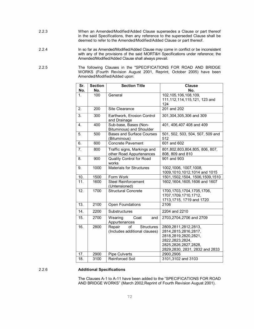
2.2.5 The following Clauses in the "SPECIFICATIONS FOR ROAD AND BRIDGE
WORKS (Fourth Revision August 2001, Reprint, October 2005) have been Amended/Modified/Added upon:
Sr. No.
Section No.
Section Title Clause No.
1. 100 General 102,105,106,108,109, 111,112,114,115,121, 123 and 124
2. 200 Site Clearance 201 and 202
3. 300 Earthwork, Erosion Control and Drainage
301,304,305,306 and 309
4. 400 Sub-base, Bases (Non-Bituminous) and Shoulder
401, 406,407 408 and 409
5. 500 Bases and Surface Courses (Bituminous)
501, 502, 503, 504, 507, 509 and 512
6. 600 Concrete Pavement 601 and 602 7. 800 Traffic signs, Markings and
other Road Appurtenances 801,802,803,804,805, 806, 807, 808, 809 and 810
8. 900 Quality Control for Road works
901 and 903
9. 1000 Materials for Structures 1002,1006, 1007,1008, 1009,1010,1012,1014 and 1015
10. 1500 Form Work 1501,1502,1504, 1506,1509,1510 11. 1600 Steel Reinforcement
(Untensioned) 1602,1604,1605,1606 and 1607
12. 1700 Structural Concrete 1700,1703,1704,1705,1706, 1707,1709,1710,1712, 1713,1715, 1719 and 1720
13. 2100 Open Foundations 2106
14. 2200 Substructures 2204 and 2210 15. 2700 Wearing Coat and
Appurtenances 2703,2704,2706 and 2709
16. 2800 Repair of Structures (Includes additional clauses)
2809,2811,2812,2813, 2814,2815,2816,2817, 2818,2819,2820,2821, 2822,2823,2824, 2825,2826,2827,2828, 2829,2830, 2831, 2832 and 2833
17. 2900 Pipe Culverts 2900,2906 18. 3100 Reinforced Soil 3101,3102 and 3103
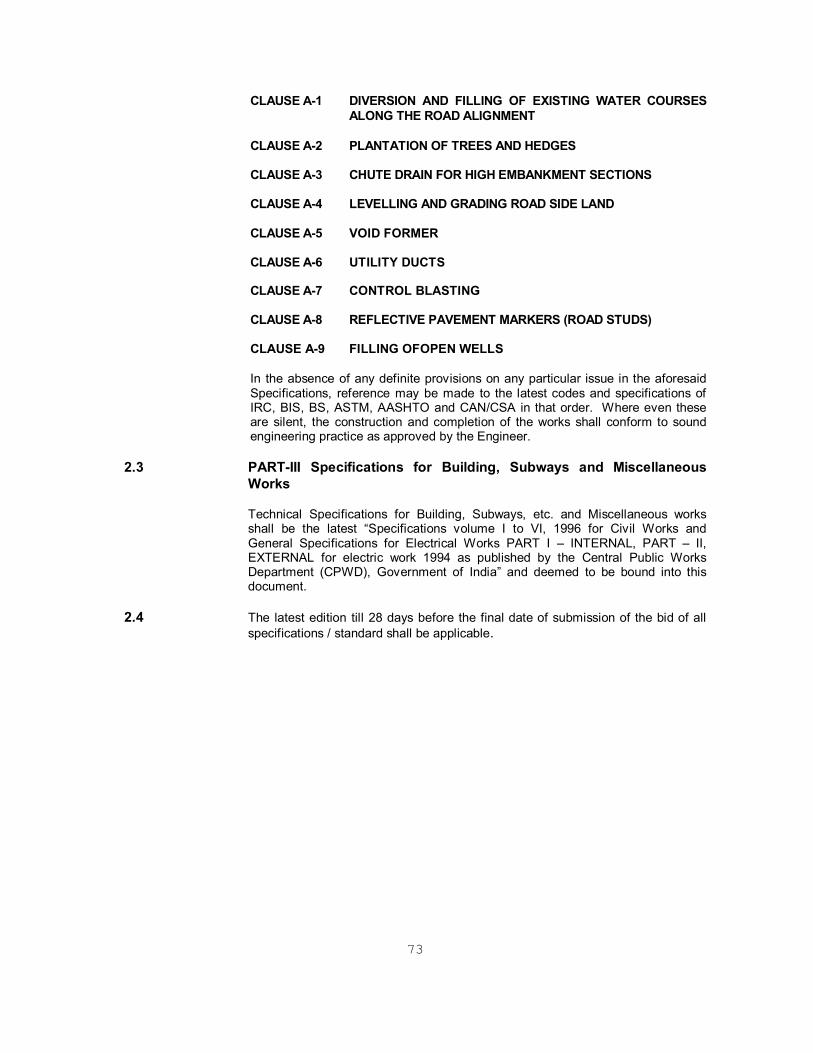
2.2.6 Additional Specifications The Clauses A-1 to A-11 have been added to the ”SPECIFICATIONS FOR ROAD
AND BRIDGE WORKS” (March 2002,Reprint of Fourth Revision August 2001).
73
CLAUSE A-1 DIVERSION AND FILLING OF EXISTING WATER COURSES
ALONG THE ROAD ALIGNMENT CLAUSE A-2 PLANTATION OF TREES AND HEDGES CLAUSE A-3 CHUTE DRAIN FOR HIGH EMBANKMENT SECTIONS CLAUSE A-4 LEVELLING AND GRADING ROAD SIDE LAND CLAUSE A-5 VOID FORMER CLAUSE A-6 UTILITY DUCTS CLAUSE A-7 CONTROL BLASTING CLAUSE A-8 REFLECTIVE PAVEMENT MARKERS (ROAD STUDS) CLAUSE A-9 FILLING OFOPEN WELLS In the absence of any definite provisions on any particular issue in the aforesaid
Specifications, reference may be made to the latest codes and specifications of IRC, BIS, BS, ASTM, AASHTO and CAN/CSA in that order. Where even these are silent, the construction and completion of the works shall conform to sound engineering practice as approved by the Engineer.
2.3 PART-III Specifications for Building, Subways and Miscellaneous
Works
Technical Specifications for Building, Subways, etc. and Miscellaneous works shall be the latest “Specifications volume I to VI, 1996 for Civil Works and General Specifications for Electrical Works PART I – INTERNAL, PART – II, EXTERNAL for electric work 1994 as published by the Central Public Works Department (CPWD), Government of India” and deemed to be bound into this document.
2.4 The latest edition till 28 days before the final date of submission of the bid of all specifications / standard shall be applicable.

74
SCOPE OF WORKS The “Works” consist of Construction of Cross Drain Structure (Vented pipe causeway) at Km 2+900 on NH-8B at Porbandar City, Gujarat. and strengthening of the existing carriageway. The works shall, inter alias, include the following, as specified or as directed: A. Road Works Site clearance; setting-out and layout; widening of existing carriageway and strengthening including camber corrections; construction of new road/ parallel service road; bituminous pavements remodeling/construction of junctions, intersections, bus bays, lay byes; supplying and placing of drainage channels, flumes, guard posts, guard rails and other related items; construction/extension of cross drainage works, bridges, approaches and other related works; road markings, road signs and kilometer/ hectometer stones; protective works for roads/ bridges; all aspects of quality assurance of various components of works; rectification of the defects in the completed works during the Defect Liability Period; submission of “As built” drawings and any other related documents; and other items of work as may be required to be carried out for completing the works in accordance with the drawings and provisions of the Contract to insure safety. B. Other Items Execution of any other items of work for the construction and completion of the Works in accordance with the provisions of the Contract including all incidental items as well as preparation and submittal of reports, plans as may be required. During the period of the Contract the right of way and all existing roads shall be kept open for traffic and maintained in a safe and usable condition. Residents along and adjacent to the works are to be provided with safe and convenient access to their properties at all times. Traffic control and traffic diversions shall be used as necessary to protect the works and maintenance will be carried out as directed by the Engineer and provided in the Contract. Any other items as required to fulfill all contractual obligations as per the Bid Documents.
75
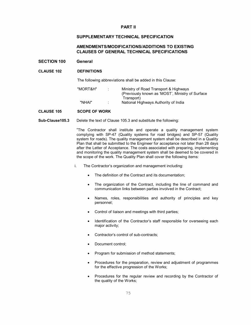
PART II SUPPLEMENTARY TECHNICAL SPECIFICATION AMENDMENTS/MODIFICATIONS/ADDITIONS TO EXISTING CLAUSES OF GENERAL TECHNICAL SPECIFICATIONS SECTION 100 General CLAUSE 102 DEFINITIONS The following abbreviations shall be added in this Clause: "MORT&H" : Ministry of Road Transport & Highways
(Previously known as ‘MOST’, Ministry of Surface Transport)
"NHAI" : National Highways Authority of India CLAUSE 105 SCOPE OF WORK Sub-Clause105.3 Delete the text of Clause 105.3 and substitute the following:
“The Contractor shall institute and operate a quality management system complying with SP-47 (Quality systems for road bridges) and SP-57 (Quality system for roads). The quality management system shall be described in a Quality Plan that shall be submitted to the Engineer for acceptance not later than 28 days after the Letter of Acceptance. The costs associated with preparing, implementing and monitoring the quality management system shall be deemed to be covered in the scope of the work. The Quality Plan shall cover the following items:
i. The Contractor’s organization and management including:
The definition of the Contract and its documentation;
The organization of the Contract, including the line of command and communication links between parties involved in the Contract;
Names, roles, responsibilities and authority of principles and key personnel;
Control of liaison and meetings with third parties;
Identification of the Contractor’s staff responsible for overseeing each major activity;
Contractor’s control of sub-contracts;
Document control;
Program for submission of method statements;
Procedures for the preparation, review and adjustment of programmes for the effective progression of the Works;
Procedures for the regular review and recording by the Contractor of the quality of the Works;
76
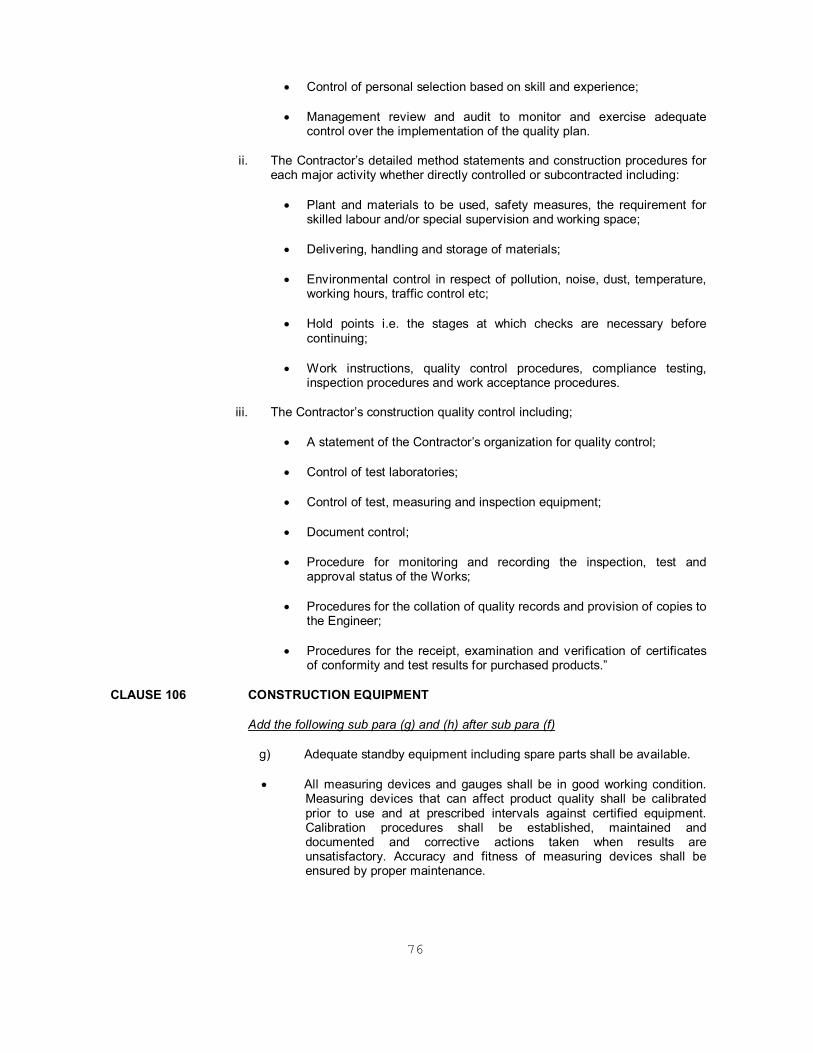
Control of personal selection based on skill and experience;
Management review and audit to monitor and exercise adequate control over the implementation of the quality plan.
ii. The Contractor’s detailed method statements and construction procedures for each major activity whether directly controlled or subcontracted including:
Plant and materials to be used, safety measures, the requirement for skilled labour and/or special supervision and working space;
Delivering, handling and storage of materials;
Environmental control in respect of pollution, noise, dust, temperature, working hours, traffic control etc;
Hold points i.e. the stages at which checks are necessary before continuing;
Work instructions, quality control procedures, compliance testing, inspection procedures and work acceptance procedures.
iii. The Contractor’s construction quality control including;
A statement of the Contractor’s organization for quality control;
Control of test laboratories;
Control of test, measuring and inspection equipment;
Document control;
Procedure for monitoring and recording the inspection, test and approval status of the Works;
Procedures for the collation of quality records and provision of copies to the Engineer;
Procedures for the receipt, examination and verification of certificates of conformity and test results for purchased products.”
CLAUSE 106 CONSTRUCTION EQUIPMENT
Add the following sub para (g) and (h) after sub para (f)
g) Adequate standby equipment including spare parts shall be available.
All measuring devices and gauges shall be in good working condition. Measuring devices that can affect product quality shall be calibrated prior to use and at prescribed intervals against certified equipment. Calibration procedures shall be established, maintained and documented and corrective actions taken when results are unsatisfactory. Accuracy and fitness of measuring devices shall be ensured by proper maintenance.
77
CLAUSE 108 SITE INFORMATION Sub-Clause 108.4 This clause shall be as follows: “Identification of quarry sites and borrow areas shall be the responsibility of the
Contractor. Materials procured from quarry sites and borrow areas identified by Contractor and to be used in Works must comply with the requirements of quality as stipulated in the Technical Specification for particular items of work.”
CLAUSE 109 SETTING OUT Sub-Clause 109.9 Delete the 2nd and 3rd sentences in Clause 109.9 and substitute the following: “Setting out of the road alignment and measurement of angles shall be done by
using Total Station.” CLAUSE 111 PRECAUTIONS FOR SAFEGUARDING THE ENVIRONMENT Add the following text after the heading to Clause 111: “In addition to the requirements of Annexure A to Clause 501, the Contractor shall
comply with the following Environmental requirements.” Sub-Clause 111.1 General Delete the text of Clause 111.1 in its entirety and substitute the following: “The Contractor shall take all necessary measures and precautions and otherwise
ensure that the execution of the Works and all associated operations on site or off-site are carried out in conformity with statutory and regulatory requirements including those prescribed elsewhere in this document.
The Contractor shall take all measures and precautions to avoid any nuisance or
disturbance arising for the execution of the Works. This shall wherever possible be achieved by suppression of the nuisance at source rather than abatement of the nuisance once generated. All vehicles deployed for material haulage shall be spillage proof.
Haul roads shall be inspected at least once daily to clear any accidental spillage.
In the event of any spoil, debris, wastes or any deleterious substance from the Site being deposited on any adjacent land, the Contractor shall immediately remove all such material at no cost to the Contract and restore the affected area to its original state to the satisfaction of the Engineer.”
Sub-Clause 111.2 Borrow Pits for Embankment Construction Delete the text of Clause 111.2 and substitute the following: “Prior approval shall be sought from the concerned State Authorities, and the
Contractor shall comply with all local environmental regulations. For all borrow areas, the actual extent of area/zones to be excavated shall be demarcated with the signboards and the operational areas shall be access controlled.
In the case of borrow from tank beds, a regrade/improvement of the inlet channels
(at least up to 100m stretch) shall be undertaken in consultation with the concerned state government departments (the Minor Irrigation department of the State PWD) and local bodies. The Contractor shall ensure that excavation of tank beds is uniform over the entire area and that the finished profile of the bed is smooth.

78
In the case of borrow from the dry highlands, all borrow areas shall be reinstated
by the formation gentle side slopes, re-vegetated and connected to the nearest drainage channel to avoid the formation of pools during/after the rainy seasons.
Plant and machinery used in the borrow areas shall conform to State noise
emission regulations. All operation areas shall be water sprinkled to contain dust levels to the National Ambient Air Quality Standards.”
Sub-Clause 111.3 Quarry Operations Delete the text of Clause 111.3 and substitute the following: “Aggregates shall be sourced only from quarry sites that comply with the
local/state environmental and other applicable regulations. Occupational safety procedures/practices for the work force in all quarries shall be in accordance with applicable laws. Quarry and crushing units shall have adequate dust suppression measures, such as sprinklers, in work areas and along all approach roads to the quarry sites. These shall preferable be located on the upwind side.”
Sub-Clause 111.5 Pollution from Hot-Mix Plant and Batching Plants Delete the 1st sentence of Clause 111.5 and substitute the following: “Bituminous hot mix plant and concrete batching plants shall be located at least
one (1) km away from the sensitive receptors (schools, hospitals, etc.) and at least 500m from urban settlements, unless otherwise required by the statutory requirements.”
Sub-Clause 111.8 Add the following text at the end of Clause 111.8: Water tankers with suitable sprinkling system shall be deployed along the haulage
roads and in the work sites. Water shall be sprinkled regularly all along the routes to suppress airborne dusts from truck/dumper movements particularly on unpaved roads. Actual frequency will be agreed with the Engineer to suit site conditions.”
After Clause 111.12 add the following new Clauses 111.13 to 111.23 Sub-Clause 111.13 Haulage Roads Existing roads used for hauling shall be strengthened and/ or widened by the
Contractor in accordance with the requirements for normal and construction traffic. Where such roads are not existing, the Contactor shall construct project specific single lane paved roads in settlement areas and gravel roads in open areas conforming to the Ministry of Road Transport and Highways (MORTH) specifications.
The alignment of the haulage roads shall be fixed to avoid agricultural land to the
extent possible. In unavoidable circumstances, suitable compensation shall be paid to the people whose land will be temporarily acquired for the duration of the operations. The compensation shall cover for loss of income for the duration of temporary acquisition and land restoration. Prior to the construction of the haul roads, topsoil shall be stripped and stockpiled for re-use.
Material dumping sites shall be access controlled to prevent the unauthorized
entry of the people, grazing cattle and stray animals. Haulage roads shall be reinstated upon completion of hauling for the use of local
communities.”

79
Sub-Clause 111.14 Water Sources and Water Quality The Contractor shall provide independent sources of water supply, such as bore
wells, for use in the Works and for associated storage, workshop and work force compounds. Prior approval shall be obtained from the relevant State Authorities and all installations shall be in compliance with local regulations. Bore wells installed and used for the project shall be left in good operating condition for the use of NHAI and local communities. The Contractor shall prevent any interference with the supply to or abstraction from, and prevent any pollution of water resources (including underground percolating water) as a result of the execution of the Works.
Areas where water is regularly or repetitively used for dust suppression purposes
shall be laid to fall to specially constructed settlement tanks to permit sedimentation of particulate matter. After settlement, the water may be re-used for dust suppression and rinsing. The Contractor shall protect all watercourses, waterways, ditches, canals, drains, lakes and the likes from pollution as a result of the execution of the Works. All water and other liquid waste products arising on the Site shall be collected and disposed of at a location on or off the Site and in a manner that shall not cause either nuisance or pollution.
The Contractor shall at all times ensure that all existing stream courses and drains
within, and adjacent to, the Site are kept safe and free from any debris and any materials arising from the Works. The Contractor shall not discharge or deposit any matter arising from the execution of the Works into any water except with the permission of the Engineer and the regulatory authority concerned.
Work force camps shall have septic tank and soak away pits. Operational areas
like POL storage areas/hot mix plant areas shall comply with local/state environmental regulations and safety procedures. Storage and handling areas shall be impervious and surrounded by an impervious lined drain to catch any accidental spills. Storm water shall be stored in lined holding tanks with oil, grease-tapping facility prior to disposal in to nearby watercourses. The trappings and sludge of holding tanks shall be disposed off in accordance with the procedures approved by the local regulatory authority.
Sub-Clause 111.15 Equipment and Vehicles used for the Works Equipments and vehicles deployed for the construction activities shall not be older
than 5 years. Equipments used for road and bridge works shall be based on new technology and shall generate noise and pollutants not exceeding the limits specified by the relevant State Authorities. Vehicles and machineries used for road and bridge works are to be regularly maintained to conform to the National Air Quality Standards. Blasting, if any, will be carried out using small charges.
Sub-Clause 111.16 Air Quality The Contractor shall device and implement methods of working to minimize dust,
gaseous and other air-borne emissions and carry out the Works in such a manner as to minimize adverse impacts on the air quality. Construction camps shall have facilities for LPG fuel. The use of firewood shall not be permitted.
The Contractor shall utilize effective water sprays during delivery, manufacture,
processing and handling of materials when dust is likely to be created, and to dampen stored materials during dry and windy weather. Stockpiles of friable materials shall be covered with clean tarpaulins, with applications of sprayed
80
water during dry and windy weather. Stockpiles of materials or debris shall be dampened prior to their movement, except where this is contrary to the Specification.
Any vehicle with an open load-carrying area used for transporting potentially dust-
producing material shall have properly fitting side and tail boards. Materials having the potential to produce dust shall not be loaded to a level higher than the side and tail boards and shall be covered with clean tarpaulins in good condition. The tarpaulin shall be properly secured and extend at least 300mm over the edges of the side of the side and tail boards.
The Contractor shall monitor air-quality once weekly in all operational areas under
the project and take the necessary steps to comply with the specified requirements. Air quality parameters will include SPM, RPM, SO2, NOX, HC and CO. operational areas include work sites, haulage roads, hot mix plants, quarries, crushing plants, stockpiles, borrow sites and spoil disposal sites.
Sub-Clause 111.17 Noise Control The Contractor shall consider noise as an environmental constrain in the planning
and execution of the Works. The Contractor shall take all necessary measures so that the operation of all
mechanical equipment and construction processes on and off the site shall not cause any unnecessary or excessive noise, taking in to account applicable environmental requirements. The Contractor shall use all necessary measures and shall maintains all plant and silencing equipment in good conditions so as to minimize the noise emission during construction works.
Any member of the work force likely to be exposed to beyond their threshold noise
levels shall be provided with protective equipment, such as earplugs, and shall be rotated every four hours.
Construction operations shall be limited to daytime hours only, particularly in the
settlement areas. Sub-Clause 111.18 Vibration Control The Contractor shall take measures during construction activities to control the
movement of the work force and construction machinery/equipment, and to avoid/ minimize activities, which produce vibrations.
Sub-Clause 111.19 Construction Camps The construction camps shall conform to the State and National building
regulations as applicable. The area for the storage of polluted materials shall be stored on impervious floors and shall be surrounded by impervious ditches in order to avoid spilling of polluted material to surrounding areas.
Construction camps shall be properly arranged to avoid noise pollution to the
nearby habitants and to avoid contamination of river and canals from wastewater drainage. To prevent such contamination, wastewater generated at the campsites shall be discharged in to soak pits. These shall be of sufficient capacity to contain 120% of estimated volume. These shall be regularly cleaned and maintained to be effective. Human excreta shall be treated though septic tanks prior to discharge and shall conform to directives and guidelines of the State. Water accumulated in tires, empty vessels and containers of all nature will be regularly cleaned to avoid the related health hazards.
81
Sub-Clause 111.20 Control and Disposal of Wastes The Contractor shall control the disposal of all forms of waste generated by the
construction operations and in all associated activities. No uncontrolled deposition or dumping shall be permitted. Wastes to be so controlled shall include, but shall not be limited to, all forms of fuels and engine oils, all types of bitumen, cement, and surplus aggregates, gravels, bituminous mixtures etc. The Contractor shall make specific provision for the proper disposal of these and any other waste products, conforming to local regulations and acceptable to the Engineer.
Spilling of oil and bituminous products during construction and transport shall be
avoided to reduce the chances of contamination of surface as well as ground water.
Degraded materials shall be disposed of in a manner as approved by the Engineer
and wastewater shall be disposed into septic tanks and soak pits etc. The Contractor shall make arrangements to cleanup spoil as soon as the work finishes in a stretch. If such sites are located outside the ROW, restoration of the site to a level acceptable to the land owner(s) will be carried out within a time period agreed between landowner(s) and the Contractor. Separators shall be used to separate POL materials from wastewater prior to discharging to the watercourses or as approved by the Engineer in conformance with directives and guidelines.
Disposal of solid waste materials shall be outlined in a plan for which
environmental clearances shall be obtained from State environmental regulatory authorities. Potential locations for solid waste disposal are the natural depressions and borrow areas. The areas used for dumping of uncontaminated debris shall be covered with 300mm soil and shall be planted. Contaminated debris shall be dumped in depressions whose bed must be impervious e.g., stone quarry sites or depressions made impervious with 450mm thick impervious floor apron as per MORT&H Technical Specifications. Each successive 1.0m layers shall be covered with 500mm thick soil layer, and the area will be covered with 300mm thick layer and planted.
Sub-Clause 111.21 Transport of Hazardous Materials Transport of al hazardous materials, in bulk or in sealed containers, shall meet the
requirements of the State regulations. Prior to ordering transport of hazardous material in bulk, the Contractor must obtain the approval of the relevant authority as well as of the Engineer. Precautionary measures and conformity with regulations shall be stated in a Method Statement for the approval of the Engineer. Sealed containers of hazardous materials shall be stored in a well-ventilated room, well guarded and secured.
Sub-Clause 111.22 Emergency Response
The Contractor shall plan and provide remedial measures to be implemented in the event of occurrence of emergencies such as spillages of oil or bitumen or chemicals. The Contactor shall provide the Engineer with a statement of the measures he intends to implement in the event of such an emergency, which shall include a statement of how he intends to provide personnel adequately trained to implement such measures.
Sub-Clause 111.23 Measurement Monitoring of Air/Water/Noise and Soil quality shall be paid as per numbers of
samples tested.
82
For Compliance of all other provisions made in this Clause 111, it shall be deemed to be incidental to the work and no separate measurement shall be made. The Contractor shall be deemed to have made allowance for such compliance with these provisions in the preparations of his prices for items of work included in the Bills of Quantities and full compensation for such compliance shall be deemed to be covered by them.”
CLAUSE 112 ARRANGEMENT FOR TRAFFIC DURING CONSTRUCTION Sub-Clause 112.4 Traffic Safety and Control Last line of Para 5 shall be read as under: “The signs shall be of approved design and of reflectory type.” Add the following paragraph at the end of the clause: “Before commencement of any construction, the Contractor shall prepare and
submit details of the arrangements for passing traffic during construction, design of barricades, signs, markings, lights, flags etc. conforming and satisfying the requirements of the “Guidelines on Safety in Road Construction Zones” of IRC: SP 55-2001 and get the same approved by the Engineer.
Sub-Clause 112.6 Measurement for Payment and Rates
a) The provision of treated shoulder including construction of temporary cross drainage structures, if required, as described in Clause 112.2 including their maintenance, dismantling and clearing debris, where necessary, shall be considered as incidental to the works and shall be Contractor’s responsibility.
b) The Construction of temporary diversion including temporary cross drainage
structures as described in sub clause 112.3, shall be measured in linear metre and the unit contract rate shall be inclusive of full compensation for construction (including supply of material, labour, tools, etc.), maintenance as per sub clause 112.5, final dismantling, and disposal.
c) All Traffic safety and control devices during construction as per sub clause
112.4 including providing, erecting and maintaining barrier, signs, markings, flags, lights and providing flag men etc shall be measured & paid in “Km”.
CLAUSE 114 SCOPE OF RATES FOR DIFFERENT ITEMS OF WORK
Sub-Clause114.2 Item (ii) of Clause 114.2 shall read as follows:
A detailed resource based construction programme including resources planning using computerized critical path network method/PERT in a form, which facilitates control of the progress of the works and consequences of any changes in terms of time. The programme shall also include detailed network, activities for the submission and approval of materials, procurement of critical materials and equipment, fabrication of special products/ equipment and their installation and testing and for all activities of the Contractor that are likely to affect the progress of work etc. including updating all such activities on the basis of decisions taken at the periodic site review meetings or as directed by the Engineer. The Contractor shall submit data via electronic media to the Engineer in a form readily compatible with Engineer’s planning system.
The first issue of the detailed construction programme including the detailed description of the system and the procedures shall be submitted to the Engineer
83
for acceptance not later than 28 days after the date of receipt of the letter of acceptance.
The contractor shall submit to the Engineer for approval & consent, the updated &
revised programme at every three months interval or as such as directed by the Engineer. The updated & revised programme shall be submitted showing the actual progress achieved (physical & financial) and the effects of the progress achieved on the timing of the remaining work including any change to the sequence of the activities.
CLAUSE 115 METHODOLOGY AND SEQUENCE OF WORK
The Clause shall be substituted as follows:
Sub-Clause115.1 Submission of Method Statement
The Contractor shall submit methods statement within 28 days after the date of letter of acceptance. The methods statement shall be submitted in two parts.
The General part of the methods statement shall describe the Contractor’s proposals regarding preliminary works, common facilities, and items that require consideration at the early stage of the Contract. The General part shall be furnished along with the first issue of the construction programme (refer clause 114.2) and shall include information on
a) Sources of materials like coarse aggregate and fine aggregate, quantity and quality of materials available in different sources;
b) Sources of manufactured materials like cement, steel, bitumen reinforcement, prestressing strands and bearings. Wherever possible the Contractor shall identify at least two sources for each of the items; he shall also submit test certificates of recently manufactured materials for the consideration of the Engineer.
c) Locations of site facilities like batching plant, hot mix plant, aggregate processing plant, crushing plant etc.
d) Details of facilities/approaches for transportation of men, equipment and materials for construction of pavements, foundations and substructure in riverbed, and plan for free traffic flow and safe drainage.
e) Information on procedures to be adopted by the Contractor for prevention and mitigation of negative environmental impact due to construction activities.
f) Any other information required by the Engineer subsequent to the scrutiny of method statement.
The General part of the Q.A. Programme shall accompany the methods statement under sub-clause 105.3.
The Special part of the methods statement shall be submitted to the Engineer by the Contractor for each important item of work like construction of embankments and subgrade, pavements, pile/well foundations, concreting, prestressing, repair and rehabilitation of existing structures, concrete superstructure, dismantling of structures and pavement and for any other item as directed by the Engineer.
84
These statements shall give information on
i) Details of personnel both for execution and quality control of the work.
ii) Equipment deployment with details of number of units, capacity, standby arrangements
iii) Sequence of construction, details of temporary or enabling works like, diversions, cofferdams, formwork including specialized formwork for superstructure, details of borrow areas, method of construction of embankment and subgrade, pavements, piles, wells, concreting procedures, details of proprietary process and products (e.g. details of prestressing systems, proprietary piling systems, bearings, expansion joints etc.) and details of equipment to be deployed. Wherever necessary, technical literature, design calculations and drawings shall be included in the methods statement.
iv) Testing and acceptance procedures including documentation.
v) Special part of the Q.A. Programme referred in clause 105.3 for the particular item of work shall be submitted along with the methods statement for the concerned activity.
vi) Engineer shall examine and approve the methods statement or direct the Contractor to resubmit the statement with required modifications. The modified statement shall be submitted within 14 days of receipt of Engineer’s comments.
The sole responsibility for the safety and adequacy of the methods adopted by the Contractor shall rest on the Contractor irrespective of any approval given by the Engineer.
Sub-Clause115.2 Approval of Proprietary Product/Process/System
Only proprietary products proven by International usage in comparable projects shall be permitted to be used. Fully authenticated details of licensing and collaboration arrangement shall be submitted by the manufacturer, where relevant.
Within 90 days of award of work the Contractor shall submit the following information for all proprietary products for approval by the Engineer.
i) Name of manufacturer and name of product/ process/ system.
Complete details of the manufacturer of the product/ process/ system shall be furnished. Details of projects where similar product/process/system has been successfully used shall be furnished. Authenticated copies of license/collaboration agreement shall be furnished.
ii) General features of the product/product process/ system.
Detailed write up with methods statements shall be furnished for each product/ process/ system. This shall include complete working drawings & installation drawings, technical specifications covering fabrication, materials, system of corrosion protection etc.,
iii) Details of product development and development testing.
85
iv) Acceptance test and criteria.
Manufacturer shall submit a quality assurance system document. Details of acceptance test and criteria of acceptance shall be furnished in this document.
v) Installation procedure.
vi) Maintenance procedure and schedule.
vii) Warranty proposal.
The Engineer may instruct any additional tests for the purpose of accepting the product. The charges of these additional tests shall be borne by the Employer only in case the product satisfies the specifications.
CLAUSE 121 FIELD LABORATORY Sub-Clause 121.2 Description Replace the words “shown in drawings” in the first sentence of first paragraph of this
Clause with the words “per provisions indicated in this Clause and at a location approved by the Engineer.” Replace “electric supply etc.” to the second sentence of first paragraph by “including uninterrupted power supply etc.”. Delete the first sentence of second paragraph “ The floor space …….. in the drawing” and substitute the following: “The floor space required for the field laboratory shall be not less than 200 sqm.“ The fourth sentence of second paragraphs “ The furnishing ………. In Table 100-2” shall read as under. “A good semi furnished office accommodation shall be provided to the Material Engineers of the Supervision Team as per the direction of the Engineer.” Add the following at the end of this Clause: “There shall also be provided a concrete paved area, for storing samples adjacent to the laboratory, of about 100 sqm and another 75 sqm shall be suitably roofed with open sides giving protection against sun and rain. Within 14 (fourteen) days of the commencement date, the Contractor shall prepare and submit a layout plan and details of the laboratory building and make/supplier of the equipment to the Engineer for his approval. The field laboratory to be provided under the Contract shall be handed over to the Engineer in finished and fully equipped condition not later than 2 months after the receipt of Notice to Commence Work, and the field laboratory with all equipment/ instrument shall be to the entire satisfaction of the Engineer. During the 2 month period starting from the Notice to Commence work, the laboratory tests shall be performed in another laboratory proposed by the Contractor and approved by the Engineer.
Sub-Clause 121.3 Laboratory Equipment
86
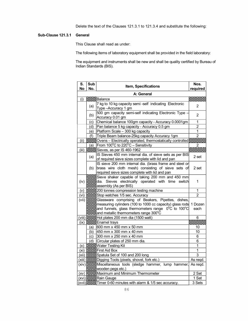
Delete the text of the Clauses 121.3.1 to 121.3.4 and substitute the following:
Sub-Clause 121.3.1 General This Clause shall read as under: The following items of laboratory equipment shall be provided in the field laboratory: The equipment and instruments shall be new and shall be quality certified by Bureau of Indian Standards (BIS).
S. No
Sub No. Item, Specifications Nos.
required A: General
(i) Balance (a) 7 kg to 10 kg capacity semi -self indicating Electronic
Type –Accuracy 1 gm 2
(b) 500 gm capacity semi-self indicating Electronic Type – Accuracy 0.01 gm 2
(c) Chemical balance 100gm capacity - Accuracy 0.0001gm 1 (d) Pan balance 5 kg capacity - Accuracy 0.5 gm 2 (e) Platform Scale – 300 kg capacity 1 (f) Triple Beam balance-25kg capacity Accuracy 1gm 2
(ii) Ovens – Electrically operated, thermostatically controlled (a) From 100oC to 220oC – Sensitivity 2
(iii) Sieves, as per IS 460-1962 (a) IS Sieves 450 mm internal dia. of sieve sets as per BIS
of required sieve sizes complete with lid and pan 2 set
(b)
IS sieve 200 mm internal dia. (brass frame and steel or brass wire cloth mesh) consisting of sieve sets of required sieve sizes complete with lid and pan
2 set
(iv) Sieve shaker capable of taking 200 mm and 450 mm
dia. Sieves electrically operated with time switch assembly (As per BIS)
1
(v) 200 tonnes compression testing machine 1 (vi) Stop watches 1/5 sec. Accuracy 2 (vii) Glassware comprising of Beakers, Pipettes, dishes,
measuring cylinders (100 to 1000 cc capacity) glass rods and funnels, glass thermometers range 0oC to 100oC and metallic thermometers range 300oC
1 Dozen each
(viii) Hot plates 200 mm dia (1500 watt) 6 (ix) Enamel trays
(a) 600 mm x 450 mm x 50 mm 10 (b) 450 mm x 300 mm x 40 mm 10 (c) 300 mm x 250 mm x 40 mm 6 (d) Circular plates of 250 mm dia. 6
(x) Water Testing Kit 1 (xi) First Aid Box 1 (xii) Spatula Set of 100 and 200 long 3 (xiii) Digging Tools (pixels, shovel, fork etc.) As reqd. (xiv) Miscellaneous tools (sledge hammer, lump hammer,
wooden pegs etc.) As reqd.
(xv) Maximum and Minimum Thermometer 2 Set (xvi) Rain Gauge 1 Set (xvii) Timer 0-60 minutes with alarm & 1/5 sec accuracy. 3 Sets

87
Sub-Clause 121.3.2 For Soils and Aggregates
B: For Soils and Aggregates (i) Water still, 3 liter/hr with fittings and accessories 1
(ii) Liquid limit device with Casagrande and ASTM grooving tools as per IS: 2720 1
(iii) Sampling pipettes fitted with pressure and suction inlets, 10 ml Capacity 2 set
(iv) Compaction apparatus (Proctor) as per IS: 2720 (Part 8) complete with collar, base plate and hammer 1 set
(v) Modified AASHTO compaction apparatus as per IS.
2720 (Part 7) 1980 or Heavy Compaction Apparatus as per IS complete with collar, base plate and hammer
1 set
(vi) Sand pouring cylinder with conical funnel and tap and
complete as per IS 2720 (Part 28) 1980 including modified equipment
4
(vii) Sampling tins with lids 100 mm dia x 75 mm ht ½ kg
capacity and miscellaneous items like moisture, tins with lid (50 grams) etc
12
(viii)
Lab CBR testing equipment for conducting CBR testing, load frame with 5 Ton capacity, electrically operated with speed control as per IS: 2720 (Part 16), and consisting of following:
1 set
(a) CBR moulds 150-mm dia – 175-mm ht complete with collar, base plate etc. 24
(b) Tripod stands for holding dial gauge holder 24 (c) CBR plunger with settlement dial gauge holder 1 (d) Surcharge weight 147-mm dia 2.5 kg weight with
central hole 48
(e) Spacer disc 148-mm dia, 47.7-mm ht. With handle 3 (f) Perforated plate (Brass) 24 (g) Soaking tank for accommodating 24 CBR moulds (h) Proving rings of 1000 kg, 2500 kg and 5000 kg capacity 1 each (i) Dial gauges, 25 mm travel- 0.01 mm/division 10 (j) Aluminium Tis 50x30m 36 nos 55x35m 36 nos 70x45m 36 nos 70x50m 36 nos 80x50m 36 nos
(ix) Standard Penetration test equipment 1 (x) Nuclear Moisture Density Meter or equivalent 2 (xi) Speedy moisture meter complete with chemicals 2 (xii) Unconfined compression test apparatus 1 set (xiii) Aggregate Impact Test Apparatus 1 (xiv) Aggregate Impact Test Apparatus as per IS 2386
(Part 4) 1963 1
(xv) Los Angeles abrasion Test Apparatus as per IS 2386 (Part 4) 1963
1
(xvi) Riffle Box of Slot size of 50mm as per ASTM C-136 1 Sub-Clause 121.3.3 For Bitumen and Bitumen Mixes
C: For Bitumen and Bituminous Mixes (i) Constant temperature bath for accommodating bitumen 2

88
test specimen, electrically operated and thermostatically controlled, 50 liter capacity temp. range ambient 80o C
(ii) Penetrometer automatic type, adjustable weight arrangement and needles as per IS. 1203 – 1978 2
(iii) Solvent extraction or centrifuge type apparatus complete (AASHTO, T-164) with extraction thimbles with stocks of solvent and filter paper
1
(iv) Laboratory mixer including required accessories about .02 cum capacity electrically operated fitted with heating jacket 1
(v) Marshall compaction apparatus automatically operated as per ASTM 1559-62 T and complete with electrically operated loading unit, compaction pedestal heating head assembly, dial micrometer and bracket for flow measurement, load transfer bar, specimen mould 100 mm dia. (4 in) with base plate, collars, specimen extractor, compaction hammer 4.53 kg (10 lb.) x457 mm (18 in) fall
1 set
(vi) Distant Reading Digital Thermometer for Measuring Temperatures in Asphaltic Mixes
As required
(vii) Riffle Box 1
(viii) Automatic Asphalt Content Gauge [Nuclear are equivalent] 1
(ix) Thin film Oven test apparatus to the requirement of AASHTO T 179, including accessories 1
(x) Ring Ball Apparatus as per IS 1205- 1978 1
(xi) Asphalt Institute Vacuum Viscometer as per IS 1206(part II) – 1978 1
(xii) BS U- Tube Modified Reverse Floro Viscometer IS 1206(Part III) – 1978 1
(xiii) Apparatus for Determination of Ductility Test as per IS 1208 – 1978 1
(xiv) Pen Sky – Martars closed Tester for testing flash and fire point as per IS 1209 – 1978. 1
(xv) Apparatus for Float Test – IS – 1210 – 1978 1
(xvi) Apparatus for Determination of water content (Dean and Shark Method) IS – 1211 – 1978 1
(xvii) Apparatus for Determination of Loss on Heading IS – 1212-1978. 1
(xviii) Apparatus of Determination of specified Gravity IS-1202-1978 1
(xix) Core cutting machine with 100mm dia. Diamond cutting Edge 1
(xx) Apparatus for Elastic Recovery test for Modified Bitumen 1
(xxi) Apparatus for Storage Stability test for Modified Bitumen 1
(xxii) Apparatus for Separation test for modified bitumen 1
Sub-Clause 121.3.4 For Cement, Cement Concrete and Materials
D: For Cement, Cement Concrete and Materials (i) Water still 1
(ii) Vicat needle apparatus for setting time with plungers, as per IS. 269-1967 1
(iii) Moulds (a) 150 mm x 300 mm ht cylinder with capping component As
89
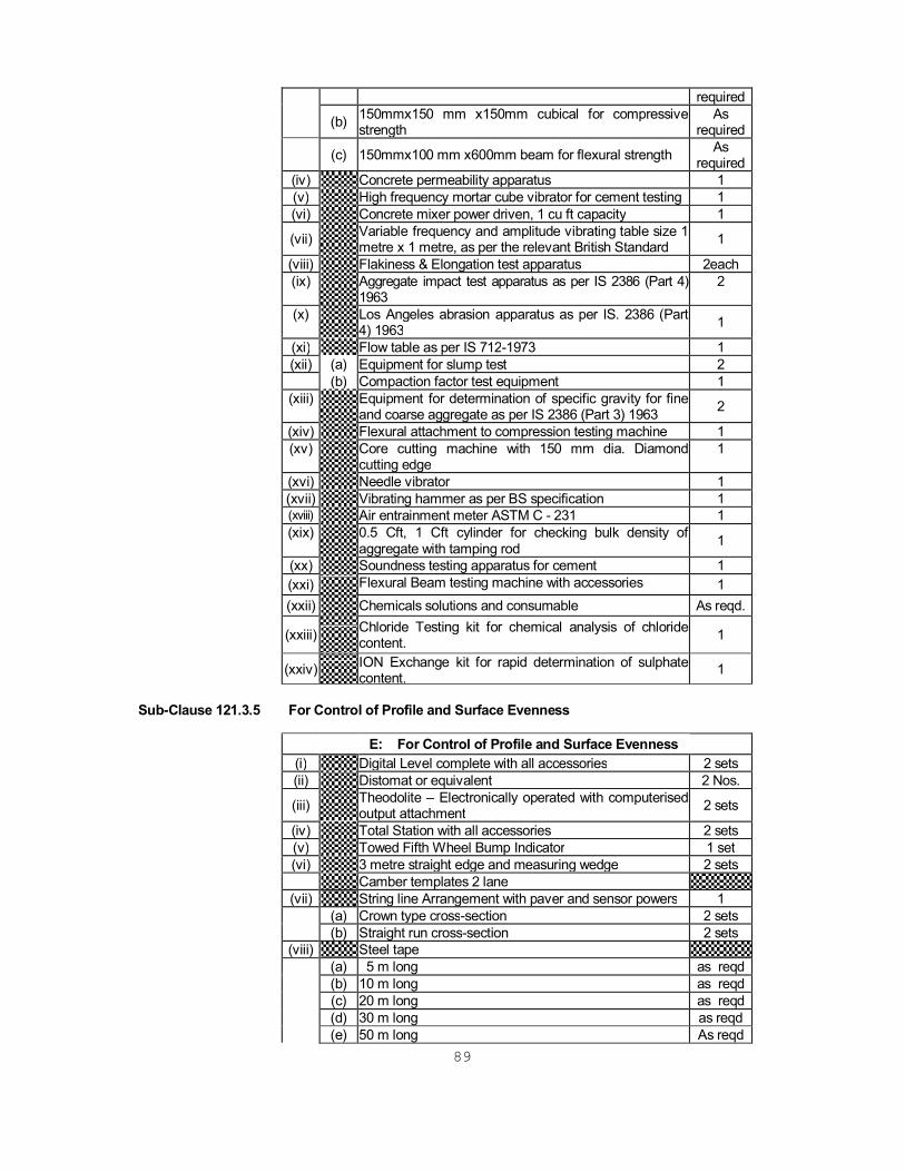
required (b) 150mmx150 mm x150mm cubical for compressive
strength As
required (c) 150mmx100 mm x600mm beam for flexural strength As
required (iv) Concrete permeability apparatus 1 (v) High frequency mortar cube vibrator for cement testing 1 (vi) Concrete mixer power driven, 1 cu ft capacity 1
(vii) Variable frequency and amplitude vibrating table size 1 metre x 1 metre, as per the relevant British Standard 1
(viii) Flakiness & Elongation test apparatus 2each (ix) Aggregate impact test apparatus as per IS 2386 (Part 4)
1963 2
(x) Los Angeles abrasion apparatus as per IS. 2386 (Part 4) 1963 1
(xi) Flow table as per IS 712-1973 1 (xii) (a) Equipment for slump test 2
(b) Compaction factor test equipment 1 (xiii) Equipment for determination of specific gravity for fine
and coarse aggregate as per IS 2386 (Part 3) 1963 2
(xiv) Flexural attachment to compression testing machine 1 (xv) Core cutting machine with 150 mm dia. Diamond
cutting edge 1
(xvi) Needle vibrator 1 (xvii) Vibrating hammer as per BS specification 1 (xviii) Air entrainment meter ASTM C - 231 1 (xix) 0.5 Cft, 1 Cft cylinder for checking bulk density of
aggregate with tamping rod 1
(xx) Soundness testing apparatus for cement 1 (xxi) Flexural Beam testing machine with accessories
1
(xxii) Chemicals solutions and consumable As reqd.
(xxiii) Chloride Testing kit for chemical analysis of chloride content. 1
(xxiv) ION Exchange kit for rapid determination of sulphate content. 1
Sub-Clause 121.3.5 For Control of Profile and Surface Evenness
E: For Control of Profile and Surface Evenness (i) Digital Level complete with all accessories 2 sets (ii) Distomat or equivalent 2 Nos.
(iii) Theodolite – Electronically operated with computerised output attachment 2 sets
(iv) Total Station with all accessories 2 sets (v) Towed Fifth Wheel Bump Indicator 1 set (vi) 3 metre straight edge and measuring wedge 2 sets
Camber templates 2 lane (vii) String line Arrangement with paver and sensor powers 1
(a) Crown type cross-section 2 sets (b) Straight run cross-section 2 sets
(viii) Steel tape (a) 5 m long as reqd (b) 10 m long as reqd (c) 20 m long as reqd (d) 30 m long as reqd (e) 50 m long As reqd

90
(ix) Precision Staff 3 Sets Note: The laboratory set-up must be complete including a set of reference standards, adequately
staffed and operational to the satisfaction of the Engineer not later than 2 months from the date of receipt of Notice to commence the works.
Sub-Clause 121.4 Ownership
This Clause shall read as under:
“Land for the laboratory shall be provided by the Contractor.” Sub-Clause 121.5 Maintenance
This Clause shall read as under:
“The Contractor shall arrange to maintain the field laboratory including sample store yards in a satisfactory manner until the issue of Taking over Certificate for the whole work. Maintenance includes all activities described in Clause 120.4 and maintenance of equipment and running of the same including chemicals and consumables.”
Sub-Clause 121.6 Measurement for Payment
This Clause shall be deleted.
Sub-Clause 121.7 Rate
The construction, supply, installation, maintenance, and operation including all consumables like chemicals & reagents etc., and all other expenses involved in connection thereto for the field laboratory shall be incidental to the work, and shall not be paid for separately.
CLAUSE 123 PROVIDING AND MAINTAINING WIRELESS COMMUNICATION SYSTEM AND
MOBILE PHONE Sub-Clause 123.2 Supply Sub-Clause 123.2.1 Wireless Communication System The first para of this Clause upto (C) be read as follows:
The Contractor shall arrange to supply, install, commission a complete wireless system which shall consist of VHF Radio – 136 to 174 MHz, one base station with 25 watt output, radio frequency output 25 watt, type of emission – 16 KOF 3 E, type of speech simplex. The system should be of approved quality suitable for a range upto 100 km, the system shall consist of following: -
a) Mobile Trans-receiver suitable for mounting on 4 wheelers with
microphone assembly, mobile antenna with cable and internal in-built speaker assembly – 25 watt output with all necessary fittings and accessories – 6 sets including one set for Employer and two sets for Engineer.
b) Base Trans-receiver with microphone assembly suitable
antenna external speaker unit with 25 watt audio output with all necessary fittings and accessories – 1set.
c) Hand set radios, which could be tuned upto 5 watt – 10 sets
including one set for Employer and three sets for Engineer.
Add the following at the end of paragraph:
91
On the issue of Taking Over Certificate, the wireless system shall become the property of the Contractor and the Contractor shall dismantle and remove the system from site.
CLAUSE 124 PROVIDING AND MAINTAINING VEHICLES FOR THE ENGINEER The heading of this clause shall read as under:
PROVIDING AND MAINTAINING VEHICLES FOR EMPLOYER/EMPLOYER’S
REPRESENTATIVE AND HIS STAFF Sub-Clause 124.1 Scope
This clause shall read as under: “The work covers providing and maintaining Diesel/Petrol driven vehicles for use by
the Employer/Employer’s representatives and his staff as in Bill of Quantities (Volume – 3) of Bidding Documents”.
Sub-Clause 124.2 Description Modify para 1 of this clause to read as under: “The vehicles for the Employer/Employer’s representative shall be of Ambassador
J1800/ISUZU (Diesel DX)/Indica model and vehicles for other personnel of Tata Sumo (4WD) model or equivalent. The vehicles shall not be older than year 2002. The number of vehicles to be provided by the contractor shall be decided by the Employer/Employer’s representatives at various times out of the total provision in the Bill of Quantities and ordered in writing”.
The last two sentences of para 2 of this clause shall read as under: “The vehicle shall be provided round the clock (24 hours) as required by the Employer.
The contractor shall also make available drivers having valid license at such times and for such duration as instructed by the Employer’s Representatives”.
Sub-Clause 124.3 Maintenance Modify line 7 of Para 1 of this Sub-Clause
Replace the words “substitute vehicle (s)” by "substitute vehicle (s) of same type as described in Clause 124.2”. Replace the amount (Rs 500 per day) in Line 9 of Para 1 of this Sub- Clause by “Rs. 1,500 per day”. Replace the amount (Rs 700 per day) in Line 6 of Para 2 of this Sub- Clause by “Rs. 2,000 per day”.
Sub-Clause 124.4: Withdrawal of Vehicles The first sentence for this Clause shall read as under: The Contractor shall withdraw particular vehicles if not required for use by
Employer/Employer’s Representative if so directed by the Employer/Employer’s Representative.
Sub-Clause 124.5: Measurement for Payment

92
This clause shall read as under: “Providing and maintaining vehicle shall be measured in terms of vehicle month basis
for each type of vehicle taking a month to consist of 28-31 days as applicable in a calendar month. No payment shall be made for the period of withdrawal as per Clause 124.4 irrespective of the fact whether the vehicle was available or not”.
Sub-Clause 124.6: Rates Replace the word “Engineer” by “Employer/Employer’s Representative”. SECTION 200 Site Clearance CLAUSE 201 CLEARING AND GRUBBING Sub-Clause 201.1 Scope Replace with following Para: This work shall consist of cutting, excavating, removing, and disposing of all
materials such as trees of girth up to 300 mm, bushes, shrubs, stumps, roots, grass weeds, rubbish etc. and top soil up to 150 mm, which in the opinion of Engineer is unsuitable for incorporation in the work including draining out stagnant water if any from the area of road land, drain, cross drainage structure and other area as specified in the drawing or instructed by Engineer. It shall include necessary excavation by harrow discs or any other suitable equipment, back filling of the pits by suitable soil, resulting from uprooting of trees & stumps and making the surface in proper grade by suitable equipment and compacted by power roller to required compaction as per Clause 305.3.4. The work also includes handling, salvaging and disposal of cleared material. Clearing and grubbing shall be performed less than one month in advance of earthwork operation and in accordance with requirement of these specifications.
Sub-Clause 201.5 The last sentence of Para 1 shall read as “Removal of stumps & roots of trees less than 300mm in girth left over after trees
have been cut by any other agency shall be considered incidental to the clearing & grubbing. The removal of stumps & roots of trees above 300mm girth left over after trees have been cut by any other agency shall be paid in terms of numbers according to their girth as per BOQ. “
Sub-Clause 201.6 Rates Sub-Clause 201.6.1 Delete “as well as stumps left over after cutting of trees carried out by another
agency” from the second sentence. Sub-Clause 201.6.4 Add new Clause The Contract unit rate for removal of stumps and roots of trees of girth above
300mm left over after cutting of trees carried out by another agency shall include excavation and back filling to required density, where necessary, and compaction, handling, salvaging, piling and disposing of the cleared materials with all lifts and leads.
CLAUSE 202 DISMANTLING CULVERTS, BRIDGES AND OTHER STRUCTURES/
PAVEMENTS

93
Sub-Clause 202.5 Disposal of Materials The first paragraph of the sub clause shall read as below All materials obtained of dismantling/milling shall be the property of the Contractor
for which he shall quote a rate for rebate in BOQ Bill No. 1, and the Contractor shall be free to use this material in work, or he may sell/dispose the material to as desired / deemed fit by him.
The existing pavement crust shall be reused as indicated below: Contractor shall be free to use dismantled / milled material, as is where is basis,
or by suitably modifying the material, or by crushing the material, or by breaking the material, and screening the same, provided it meets the specifications and is approved by the Engineer.
Sub-Clause 202.6 Measurements for Payment This Clause shall read as: The work of dismantling structures shall be paid for in units indicated below by taking
measurements before and after, as applicable:
(i) Dismantling brick / stone masonry / plain concrete / reinforced concrete including reinforcement.
Cum
(ii) Dismantling pavement structures such as Sub base / Base Course, Bituminous wearing course, Concrete wearing course
Cum
(iii) Dismantling pipes, guard rails, road kerbs, gutters and fencing Linear Meter
(iv) Dismantling Guard Stones/KM stones/Sign post/Hect. Stones Nos (v) Dismantling RCC railing Linear
Meter (vi) Dismantling angle type expansion joints of bridges Linear
Meter (vii) Dismantling of railing kerb Cum (viii)
Dismantling of Concrete Edge strip without damaging existing structure
Linear Meter
(ix) Dismantling of Drainage spout including cleaning entire area, enclosure of metallic bearing
Nos.
(x) Dismantling of Stone pitching/ boulder apron/ brick soling/ stone soling
Cum
Sub-Clause 202.7 Rates Add at the end of this sub clause: The contract unit rates for various items of rebate shall be on the full quantities obtained from dismantling taking into account all the operations for reuse of salvaged materials and disposal of the balance of material within all leads and lifts. SECTION 300 Earthwork, Erosion Control And Drainage CLAUSE 301 EXCAVATION FOR ROADWAY AND DRAINS Sub-Clause 301.1 Scope Add the following as second paragraph under this clause:

94
“The work shall also include excavation for channel training at culverts/bridges, excavation of existing shoulders and medians for purposes of widening the pavement and excavation of existing embankment for reconstruction to specification.”
Sub-Clause 301.3.3 Excavation – General Delete the last two sentences of para 5 beginning and ending with: “If trees were removed…..by the Engineer.” and “The cost of planting…to the work.” Sub-Clause 301.3.7 Excavation of road shoulders/verge/medians for widening of pavement or
providing treated shoulders: The title of this Clause shall read as under: "Excavation of road shoulders/verge & medians for widening of pavement or for
providing treated/paved shoulders and medians”. Sub-Clause 301.8 Measurements for Payment In first line of first para add “and drains” after the word “roadway” Delete the last para from “works involved……” and substitute: “Works involved in excavation for roadway and drains shall be measured in unit
indicated below:
Excavation in all classes of soil …cu.m. Excavation in ordinary rock …cu.m. Excavation in hard rock …cu.m. Preparing Rocky Sub-Grade …sq.m. Stripping, storing and reapplication of top soil …cu.m. Disposal of surplus or unsuitable material beyond Initial 1000m lead …cu.m
Sub-Clause 301.9.2 This clause shall be read as follows:
"The contract unit rate for loosening and recompacting at sub-grade level shall include full compensation for loosening to the specified depth, removing the loosened soil outside the roadway excavation, rolling the surface below, breaking the clods, spreading the excavated soil in layers, watering where necessary and compacting to the requirements."
CLAUSE 304 EXCAVATION FOR STRUCTURES Sub-Clause 304.3.2 Excavation At the end of 1st paragraph of Clause 304.3.2 insert the following additional sentences:
“ The Contractor shall ensure the stability and structural integrity of adjacent existing foundations and structures and if necessary shall, at his own expense, install temporary or permanent sheet piles, coffer dams, shoring or similar as support or protection to the satisfaction of the Engineer.”
Sub-Clause 304.3.4 Preparation of Foundation
95
In para 2 and 3 of clause 304.3.4 substitute 'Concrete M15' in place of '1:3:6 nominal mix'.
Sub-Clause 304.4 Measurement for Payment
In the second sentence of Para 1 of Clause 304.4 after the words “……… cutting of slopes,” insert the words “protection/support to existing structures,”
CLAUSE 305 EMBANKMENT CONSTRUCTION Sub-Clause 305.2 Material and General Requirements Sub-Clause 305.2.1 Physical Requirements: Sub-Clause 305.2.1.2 Add the following after second paragraph: “Soils having medium and high swelling potential shall be defined on the basis of
Liquid Limit, Plastic Limit, Shrinkage Limit, Gradation, Free swelling Index, Field dry Density and Field Moisture Content and types of Clay minerals present in the soil and as directed by the Engineer. The location and the extent of these soils with medium to high swelling potential should be defined as directed by the Engineer.”
Sub-Clause 305.2.1.4 Delete second sentence “However, the Engineer ……….. requirements of these Specifications” of Clause 305.2.1.4.
Sub-Clause 305.2.2.2 Borrow Materials Para 1 of this Clause shall read as under:
”No borrow area shall be made available by the Employer for this work. The arrangement for the source of supply of the material for embankment and sub-grade as well as compliance to the different environmental requirements in respect of excavation and borrow areas as stipulated, from time to time, by the Ministry of Environmental and Forest, Government of India and the local bodies, as applicable, shall be the sole responsibility of the Contractor.” In Clause 305.2.2.2 after the 7th paragraph delete Table 300-2 and substitute the following:
Table 300-2 Compaction Requirements of Embankment and Subgrade
S. No. Type of Work/Material
Relative Compaction as %age of maximum
laboratory dry density as per IS 2720 (Part 8)
1 Subgrade and earthen shoulders Not less than 98% 2 Embankment Not less than 95% 3 Expansive clays Not allowed 4 Design CBR of Subgrade & Shoulder should not be less than 8
Para 8 of this Clause given below Table 300-2 shall read as under: The contractor shall at least 21 working days before commencement of construction of
embankment and the subgrade; submit the following to the Engineer for approval:
(i) The values of maximum dry density and optimum moisture content obtained in accordance with IS: 2720 (Part 8) for each fill material proposed to be used in the construction of embankment and subgrade.
(ii) The graphs of Density plotted against moisture content from which each of the
96
values in (i) above of maximum dry density and optimum moisture content were determined.
(iii) The dry density-moisture content-CBR relationships, heavy compactive efforts
conforming to the IS 2770 (part 8) for each of the fill material proposed to be used in the subgrade.
The above information shall form the basis for compaction only upon its approval by
the Engineer.” Sub-Clause 305.3 Construction Operations Sub-Clause 305.3.4 Compacting Ground Supporting Embankment/Subgrade Para 1 of this clause shall be read as “Where necessary the original ground shall be leveled, scarified, mixed with water
and then compacted by rolling to facilitate placement of first layer of embankment so as to achieve minimum dry density as given in Table 300-2”.
In Para 2 replace “97%” by “98%”. Add at the end of Para 2
”Backfilling layers in pits, trenches and below the original ground are to be compacted to the relative natural ground density. The natural ground density shall be determined by conducting field density tests at three widely spaced locations along the central line of the proposed additional carriageway at a depth between 0.5m to 1.0m. Samples of natural ground are collected at each location, and are tested in accordance with IS: 2720 (Part 8). The relative density (i.e. the percentage of the field dry density to the laboratory maximum dry density) is assessed for each sample, and the greatest relative density obtained is selected as the “natural ground density”. If the natural ground density is less than 85% then these are to be compacted after necessary watering so as to achieve not less than 85% of relative compaction”.
“Where necessary to facilitate compaction of the subgrade to 98% relative compaction as stated above, a further depth of maximum of 0.2m thickness shall be loosened, watered and compacted in accordance with Sub Clause 305.3.5 and 305.3.6 to not less than 95% of dry density determined in accordance with IS: 2720(Part-I)”.
Sub-Clause 305.3.5.2 In para 3, substitute "IS: 2720 (Part 8)" for "IS: 2720 (Part 7)”. Sub-Clause 305.3.6 Compaction The second para of this Clause shall read as under: "Vibratory roller of not less than 8-10 tonne static weight with plain or pad foot drum or
pneumatic tyre roller of 15-20 Tonne weight having tyre pressure of at least 7 kg/sqcm shall be used for compaction.”
Insert the following sentence before the last sentence of Paragraph 5. “The co-relation between sand replacement densities and nuclear gauge densities
97
shall be based on trials with minimum 30 coherent density measurements”. Sub-Clause 305.8 Measurement for Payment
Para 1 shall be read as "Earth embankment/sub-grade construction shall be measured separately by taking cross sections at intervals after clearing and grubbing and if necessary compaction of original ground before the embankment work starts and after its completion and computing the volumes of earthwork in cubic metres by the method of average and areas."
Sub-Clause 305.9 Rates Sub-Clause 305.9.1 Add “including removal of topsoil after word “ materials” appearing in first line of
item (v). Add new sub section as (xiv) slush removal. CLAUSE 306 SOIL EROSION AND SEDIMENTATION CONTROL Sub-Clause 306.4 Measurements for Payment Substitute Clause 306.4 as follows: "All temporary sedimentation and pollution control works shall be deemed as
incidental to the earthwork and other items of work and as such no separate payment shall be made for the same."
Sub-Clause 306.5 Rates This clause shall be deleted. CLAUSE 309 SURFACE/SUB-SURFACE DRAINS Sub-Clause 309.2 Surface Drains
Add the following paragraphs after end of the fifth Para of this clause. “Drains in super-elevations shall be constructed as per drawings. Geotextile
membrane if specified for these drains shall conform to Sub-Clause 702 of Section 700”.
“The roadside land between toe of road embankment & drain shall be levelled &
sloped towards the drain as per drawing and Additional Specification Clause A-8.” Sub-Clause 309.3 Sub- Surface Drains Sub-Clause 309.3.1 Scope The first sentence of this clause should read as: “Sub-surface drains shall be close jointed perforated pipes, surrounded by granular
material laid in a trench to drain the pavement courses.” Sub-Clause 309.3.2 Materials Grading requirements for filter material shall conform to Class I of Table 300-3.
98
Sub-Clause 309.3.2.A Pipe The first and second sentences of this clause shall read as: “Perforated pipes for the drains are of PVC. The size and grade of the pipe to be used
is as specified in the drawing.” Sub-Clause 309.3.4 Laying of Pipe and Backfilling Delete para 4 of this clause. Sub-Clause 309.4 Measurements for Payment
This Clause shall read as: “Construction of drains shall be measured as finished work in position as below:
a) Unlined ditch drain …… Running metre b) Semi-Circular median drain as shown in the
drawing with PCC M20, NP2 pipe, levelling concrete M15 and filter media.
…… Running metre
c) Open cross-drain in paved median as per drawing with PCC grade M20 & levelling concrete M15.
…… Running metre
d) Paved open/Covered drain (i) Levelling concrete M15 …… Cubic metre (ii) Course rubble masonry …… Cubic metre (iii) Stone pitching grouting with CM 1:3 …… Cubic metre (iv) RCC grade M20 …… Cubic metre (v) HYSD Reinforcement …… Tonne (vi) Precast perforated slab …… Nos. (vii) Iron grating …… Nos. e) Drains in super-elevated sections (i) Catchpits …… Nos. (ii) RCC pipe 450 mm dia. …… Running metre f)
Sub-surface drains Running metre
Sub-Clause 309.5 Rates The Clause shall read as under: The Contract unit rates for surface and subsurface drains shall be payment in full for all items such as excavation, dressing the sides and bottom; providing lining, turfing, pitching, masonry, concrete and plastering; providing, laying and jointing pipes; providing, laying and compacting backfill and bed of granular material; providing, fixing, and painting of cover etc. including full compensation for all materials, labour, tools, equipment and other incidentals to complete the work as shown on drawings with all leads and lifts. The levelling & sloping of road side land, provision of inlets, gratings, sumps, outlet pipes, bedding, disbursers etc. wherever required shall be incidental to construction of drain. The Contract unit rate for the drains and selected items shall be paid as per BOQ items given in Clause 309.4. SECTION 400 Sub-Bases, Bases (Non Bituminous) and Shoulders
99
CLAUSE 401 GRANULAR SUB BASE Sub-Clause 401.1 Scope Add the following at the end of this Clause: “A site trial shall be performed in accordance with Clause 901.16.” Sub-Clause 401.2 Materials Sub-Clause 401.2.1 Para 1 of this Clause shall be read as under: "The material shall be free from organic or other deleterious constituents and conform
to the Grading 1 given in Table 400-1 with the percentage passing 0.075mm size restricted to 5%. The portion of the total aggregate passing 4.75 mm sieve shall have a sand equivalent value of not less than 50 when tested in accordance with the requirement of IS: 2720 (Part – 37).”
Delete Para 2 of Clause 401.2.1. Sub-Clause 401.2.2 Physical Requirements Add at the end of this clause as under:
The Contractor shall, at least 21 working days before the commencement of the construction of the sub-base course, submit to the Engineer, the results for approval of the laboratory testing on the physical properties defined above. The construction of the sub-base course shall be taken up only upon the Engineer’s approval of the material.
CLAUSE 406 WET MIX MACADAM SUB BASE/BASE Sub-Clause 406.2.1.1 Physical Requirements Delete the second sentence beginning with "If crushed gravel…” and ending with “….
fractured faces." and add as under: “The constituents of the aggregates shall be produced by integrated crushing and
screening plant (Impact or Cone type of capacity 200T/hour) and, unless otherwise instructed by the Engineer, crushing shall be carried out in at least two stages. The fraction of material passing through 4.75mm sieve shall also be crusher run screening only.”
Sub-Clause 406.3.3 Preparation of Mix Para 1 of Clause 406.3.3 shall be read as under:
“Wet mix Macadam shall be prepared in an approved Wet Mix Macadam mixing plant of 200T/hour capacity having provision for controlled addition of water and forced/positive mixing arrangement.”
Sub-Clause 406.3.4 Spreading of Mix Substitute para 2 of clause 406.3.4 as under:
100
“The mix shall be spread by a WMM paver finisher capable of paving minimum 4.5m
to 9.0m width. Clause 406.3.5 Compaction Delete second sentence of para 1 of Clause 406.3.5. Sub-Clause 406.4 Opening to Traffic The Clause shall be read as follows:
No vehicular traffic of any kind shall be allowed on the finished wet mix macadam surface.
CLAUSE 407 SHOULDERS, ISLANDS AND MEDIAN Sub-Clause 407.2 Add after granular material in second line “/dismantled bituminous / granular
material / WBM materials”. Sub-Clause 407.4.2 Add after granular material in eight line: “/dismantled bituminous / granular material / WBM materials”. Sub-Clause 407.6 Measurements for Payment This clause shall be read as under: "Construction shall be measured as finished work in position as below:
a) Shoulders (Earthen/Hard/Paved)
(i) For excavation : in cum
(ii) For earth work/granular fill : in cum (iii) For sub-base, base, surfacing courses : in units of respective items (iv) For kerb : in running meters
b) Island and Medians
(i) For earthwork : in cum (ii) For kerb : in running meters (iii) For turfing : in sqm (iv) For sub-base, base and tile/slab finish :in sqm complete as per Clause 409.”
CLAUSE 408 CEMENT CONCRETE KERB AND KERB WITH CHANNEL Sub-Clause 408.3 Type of Construction This Clause shall be read as under:

101
The cement concrete kerb shall be cast in situ laid with kerb casting machinery. Sub-Clause 408.5 Construction Operations Clause 408.5.1 shall be read as under: For the sections under the symmetrical 4-laning schemes, no foundation concrete in
M15 shall be required and the cast- in-situ concrete kerb in M20 concrete shall be laid on the existing pavement structure. However, for the sections with the additional carriageway constructed on the sides of the existing pavement or along sections near bridge approaches or along service roads, kerb shall be laid on firm foundation of minimum 100mm thickness of cement concrete of M15 grade cast-in-situ or on extended width of pavement. The foundation shall have a projection of 50mm beyond the kerbstone. Before laying the foundation for kerbs, the base shall be leveled and slightly watered to make it damp.
Sub-Clause 408.6 Measurements for Payment Para 2 shall be read as under: Foundation of kerb where separately provided with cement concrete grade M 15 shall
be paid separately. CLAUSE 409 FOOTPATHS AND SEPARATORS Sub-Clause 409.2 Materials Parts (a) and (c) of this Clause 409.2 shall be deleted. SECTION 500 Base and Surface Courses (Bituminous) Sub-Clause 501.2 Materials Sub-Clause 501.2.2 Delete “Crushed gravel or other hard material” from second Line of Para 1.” Para 3 is deleted. Sub-Clause 501.3 Mixing Para 1, Line 3 and 4, replace the word, “Adequate Capacity” with “Hot mix plant of
Batch mix type of Minimum capacity of more than 120T per hour.” Sub-Clause 501.5.3 Spreading Para 1 is replaced with the following:
"Bituminous mix shall be spread with paver fitted with electronic sensing device and string line arrangement (supported by steel pegs @ 5m apart) on either side of paving width for automatic levelling, surface evenness and profile control. Use of string lines is compulsory to provide signal to electronic sensing device fitted with a Paver Finisher".
Sub-Clause 501.6 Compaction Para 2, Line 13; sentence starting with “the intermediate rolling ……………” is
replaced by “Intermediate rolling shall be done with a Pneumatic roller of 150-250kN weight having a tyre pressure of at least 0.7Mpa.
102
Add new Para, “Rolling shall be continued till the density achieved, satisfied the
requirement of Clause 903.4.2. CLAUSE 502 PRIME COAT OVER GRANULAR BASE Sub-Clause 502.2.3 Choice of Primer This clause shall be read as under: "Primer: The primer used for prime coat shall be bitumen emulsion complying with IS
8887 and CSS – I Grade conforming to ASTM D 2397/AASHTO M 140, and shall be refinery produced. The particular grade to be used for the work shall be got approved by the Engineer.”
CLAUSE 503 TACK COAT Sub-Clause 503.2 Materials This clause shall be read as under: "Binder: The binder used for tack coat shall be bitumen emulsion complying with IS
8887 and CSS – I Grade conforming to ASTM D 2397/AASHTO M 140, and shall be refinery produced. The particular grade to be used for the work shall be got approved by the Engineer.”
CLAUSE 504 BITUMINOUS MACADAM Sub-Clause 504.2.1 Bitumen
This Clause shall be read as under: “The binder shall be paving bitumen of Penetration Grade S65 complying with Indian Standard Specifications for “Paving Bitumen”, IS: 73.”
Sub-Clause 504.2.2 Aggregates Delete the words ‘crushed gravel/shingle or other stones’ from the first sentence of
Clause 504.2.2. Delete third para of Clause 504.2.2. Sub-Clause 504.2.5 Proportioning of Materials Add below Table 500 - 4 of Clause 504.2.5 as under: “Grading - 1 shall be used for compacted thickness of a layer of 75mm and above
while Grading - 2 shall be used for compacted thickness of a layer of less than 75mm thickness.”
Sub-Clause 504.8 Rate After the words “required operations” in second line of this clause, add the words
“except the items of tack coat and prime coat (if any).” CLAUSE 507 DENSE GRADED BITUMINOUS MACADAM Sub-Clause 507.2.1 Bitumen
103
Delete words “indicated in Table 500-10” and insert “grade of S-65” in 3rd and 4th line.
Sub-Clause 507.2.2 Coarse Aggregates Delete the words 'crushed gravel or other hard material' from the first sentence of
Clause 507.2.2. Delete para 2 of sub-clause 507.2.2. Sub-Clause 507.2.5 Aggregate Grading and Binder Content In Table 500-10, the following may be substituted:
Grading 1 2 Layer Thickness >75mm to 100mm 50-75mm Bitumen grade (pen) 65 65
The Note-1 below Table 500-10 shall read as: “The grading of the aggregate mix as used in work shall be a smooth curve within and
approximately parallel to the envelope in Table 500-10”. Sub Clause 507.3 Mixture Design Sub-Clause 507.3.1 Requirement for the Mixture Add the following requirements to the list of Table 500-11:
Water sensitivity (ASTM D1075): Retained stability (Ratio of Marshal Stability for 24 h Immersion and 30min Immersion in water at 60 degree centigrade temperature) = not less than 75 %
Stability to flow ratio = 205 to 410
Filler- Bitumen ratio = 0.6 to 1.2
Sub-Clause 507.4.9 Rolling Add at the end of Para 1
“ The rolling shall be continued till the density achieved is at least 98% of that of laboratory Marshall specimen compacted as detailed in Table 500-11.”
Sub-Clause 507.9 Rate Add the words “except for item of prime coat and tack coat” after the words
“required operations” in 2nd line. CLAUSE 509 BITUMINOUS CONCRETE Sub-Clause 509.2.5 Aggregate Grading and Binder Content The Note -1 below Table 500-18 shall be substituted: “The grading of the aggregate mix as used in work shall be a smooth curve within and
approximately parallel to the envelope in Table 500-18-Grade I”.
104
Sub-Clause 509.3 Mixture Design Sub-Clause 509.3.1 Requirement for the mixture Add the following requirements to the list of Table 500-19:
Water sensitivity (ASTM D1075): Retained stability (Ratio of Marshal Stability for 24 h Immersion and 30min Immersion in water at 60 degree centigrade temperature) = not less than 75 %
Swell Test (Asphalt Institute, MS-2, No.2), maximum = 1.5%
Sub-Clause 509.9 Rate Add the words “except for item of tack coat” after the words “required operations”
in 2nd line. SECTION 600 Concrete Pavement CLAUSE 601 DRY LEAN CEMENT CONCRETE SUB-BASE Sub-Clause 601.4 Subgrade Sentence 2 shall be read as: “The Lean Concrete sub-base shall be laid on drainage layers as per drawings. The
drainage layer shall be as per grading class III of Table 300-3. The material shall be crushed stone aggregate. The CBR of drainage layer shall be more than 30.
Sub-Clause 601.5 Construction Sub-Clause 601.5.4 Placing Add in the beginning of Clause 601.5.4: One day before placing of the dry lean cement concrete sub-base, the surface of
the drainage layer shall be given a fine spray of water and rolled with a smooth wheeled roller after a lapse of 2-3 hours after watering. The Engineer may instruct another fine spray of water to be applied just before placing of the dry lean cement concrete sub-base.
Sub-Clause 601.5.7 Curing Add the following in last. Method ‘a’ shall be adopted. CLAUSE 602 CEMENT CONCRETE PAVEMENT Sub-Clause 602.1 Scope Add the following at the end of this Clause: “A site trial shall be performed in accordance with Clause 901.16.” Sub-Clauses 602.2 Materials

105
Sub-Clause 602.2.2 Cement Replace the last para of Clause 602.2.2 with: “It is the responsibility of the Contractor to test and propose the type of cement
which will result in a concrete complying in all respects with the specifications. Cement to be used shall be obtained in bulk. Bulk cement shall be stored in accordance with Clause 1014. The cement shall be subjected to acceptance test just prior to use.”
Sub-Clause 602.2.4.2 Coarse Aggregate Add following para at the end of clause: “The Stone Polishing Value, as measured by BS: 812 (Part 114), shall not be less
than 55.” Sub-Clause 602.2.4.3 Fine Aggregate
Add the following at the end of this Clause: “The fine aggregates shall be natural sand conforming to the grading Zone-II as per IS: 383.”
Add the following as Clause 602.2.4.4 Sub-Clause 602.2.4.4 Combined All-In Aggregate
The grading limits for all-in aggregates shall be as per IS: 383 for 20mm nominal size aggregates and as given under:
IS Sieve Designation Percentage Passing 40mm 100 20mm 95-100
4.75mm 30-50 600 micron 10-35 150 micron 0-6
Sub-Clause 602.2.2.5 Water This clause shall read as under:
“Water used for mixing and curing shall conform to Clause 1010 of Section 1000.”
Sub-Clause 602.2.7 Premoulded Joint Filler Replace Clause 602.2.7 with:
“Joint filler board for expansion joints shall be of the same thickness as the specified joint width within a tolerance of + 1.5mm and shall comply with the requirements of IS: 1838 or BS Specification No.2630. The filler for each joint shall be furnished in a single piece for the full depth and width required for the joint. Holes to accommodate dowel bars shall be accurately bored or punched to give a sliding till on the dowel bars.”
Sub-Clause 602.2.8 Joint Sealing Compound Replace Clause 602.2.8 with:

106
“The joint sealing compound shall be hot applied elastomeric type, complying with AASHTO M282 for joints in asphalt pavements or joints between asphalt and concrete pavements, and cold applied polyurethane or polysulphide type complying with BS: 5212 –1 990 for joints in concrete pavements.
The joint sealant shall be resistant to age hardening and shall have flexibility to
accommodate movements of minimum 25% of the joint width as shown in the drawings without risk of breaking of the sealant or adherence failure. The dimensions shall be so proportioned; that the adherence to the groove walls is fully intact within the movements limits.
Suitable primers as recommended by the manufacturers of each type of joint sealant shall be used. Sub-Clause 602.3 Proportioning of Concrete Sub-Clause 602.3.3. Concrete Strength Sub-Clause 602.3.3.1 The last sentence of this Para shall read as under:
“The water content shall be the minimum required to provide the agreed workability for full compaction of the concrete to the required density as determined by the trial mixes or other means approved by the Engineer and the maximum free water-cement ratio shall be 0.45.”
Add the following at the end of this Clause:
“The concrete for the rigid pavement shall be of M40 Grade with a 28-day compressive strength of not less than 40 MPa and a flexural strength of not less than 4.0 MPa.”
Sub-Clause 602.3.5 Design Mix Add at the end of Para 1, the following parameters shall be used for design mix i) Characteristics flexural strength at 28 days = 4.0 MPa ii) Target mean strength at 28 days = 5.0 MPa iii) Water cement ratio = 0.45 maximum iv) Slump as per IS: 1199 = 31+15 mm. Sub-Clause 602.6 Joints Sub-Clause 602.6.4 Longitudinal Joint Add Clause 602.6.4.3 after Clause 602.6.4.2: Sub-Clause 602.6.4.3 Joints at the junction of rigid and flexible pavements: Joints shall be provided at the junctions of rigid and flexible pavement as shown in
drawings. Where due to unavoidable reasons, the joints cannot be constructed at the junction of the two contract packages dowel bars shall be provided in the rigid pavement and other measures as directed by the Engineer taken Joints between bituminous pavement and concrete pavements (at locations other than junction between contract packages) shall be constructed.
107
Sub-Clause 602.9 Construction Sub-Clause 602.9.3.2 Batching Plant and Equipment Add at the end of Clause: “The batching plant should have suitable devices for adjusting the slump of the
mix and should have facility for the computer printouts of every batch produced”. Sub-Clause 602.9.9 Curing Add the following at the end of clause 602.9.9. Immediately after sawing the joints the concrete in the groves shall be covered by
curing membrane. Sub-Clause 602.10 Trial Length Sub-Clause 602.10.2 Add new para to Clause 602.10.2 as follows: “All trials shall be carried out using the same paving width and slab thickness as
used in the permanent works.” Sub-Clause 602.10.5.3 Density Replace the entire Clause 602.10.5.3 with: “(v) In-situ density shall be assessed as described in Clause 903.5.2.2 from at
least 3 cores drilled when the concrete is not less than 7 days old. Should any of the cores show honey-combing in the concrete, the trial length shall be rejected and further use of the spreading and compacting unit shall not be permitted until further trials have shown that modification can be made which will result in adequate compaction.”
Sub-Clause 602.11 Preparation and Sealing of Joint Grooves. Sub-Clause 602.11.3 Sealing with Sealant. Sub-Clause 602.11.3.1 Replace first sentence with: “Prior to application of the sealant the primer recommended by the manufacturer
shall be applied.” Sub-Clause 602.11.3.3 Replace the entire Clause 602.11.3.3 with: “Sealant complying with Clause 602.2.8 shall be used. Cold applied sealant shall
be mixed and applied within the time limit specified by the manufacturer. Primers shall be applied neatly with an appropriate brush or as recommended by the manufacturer.
Sub-Clause 602.13 Opening to Traffic Replace the entire Clause 602.13 with: “No vehicular traffic (including the Contractor’s vehicles) shall be allowed on the
finished surface until a field flexural strength of minimum 4.0 MPa has been achieved. It is the responsibility of the Contractor to produce a sufficient number of series of test specimens to verify the field flexural strength”.
Prior to opening to traffic the joints shall be sealed and areas adjacent to the
108
pavement shall be completed to a degree that will ensure traffic safety. Opening to traffic shall not constitute a final acceptance of the pavement.”
SECTION 800 Traffic Signs, Markings & Other Road Appurtenances CLAUSE 801 TRAFFIC SIGNS Sub- Clause 801.1 General Sub- Clause 801.1.2 This Clause shall read as follows: “The signs shall be reflectorised. They shall be retro-reflectorised type and made of
encapsulated lens type reflective sheeting vide Clause 801.3, fixed over aluminium sheeting as per these specifications.”
Sub-Clause 801.2.6 This clause shall read as under: “The aluminium sheet used for signs shall be 2mm thick.” Sub- Clause 801.3 Traffic Signs Having Retro-reflective Sheetings Sub-Clause 801.3.1 General Requirements The fifth sentence of this clause should read as under: “The reflective sheeting shall be of High Intensity grade with encapsulated lens.” Delete last sentence of this clause. Sub-Clause 801.3.3 Engineering Grade Sheeting Delete this clause. Sub-Clause 801.3.6 This clause shall read as under: “Cut-out messages and borders, wherever used, shall be made out of retro-reflective
sheeting as per Clause 801.3.2, except those in black which shall be of non-reflective sheeting.”
Sub-clause 801.3.7 Add following in the clause
All the facility information and place identification signs shall have blue (Indian standard colour No. 166: French Blue) background and white letters.
Sub-Clause 801.3.11 Warranty and Durability The first and second sentences of this clause shall read as under: “The Contractor shall obtain from the manufacturer a seven-year warranty for
satisfactory field performance including stipulated retro-reflectance of the retro-reflective sheeting of high intensity grade and submit the same to the Engineer. In addition, a seven year warranty for satisfactory in-field performance of the finished sign with retro-reflective sheeting of high intensity grade, inclusive of the screen printed or cut-out letters/legends and their bonding to the retro-reflective sheeting shall be obtained from the Contractor/Supplier and passed on to the Engineer.”
Sub-clause 801.4.1 The third & fourth sentence of clause shall read as follows:

109
Sign posts shall be of MS pipe 80mm dia. (NB-MW). Post shall be embedded in concrete (M-15) for safeguard against theft. The cost of signpost and its foundation complete including excavation & concrete shall be deemed to be included in the rate of signboard
Sub-clause 801.4.2 Add following at the end of this clause:
“The sign back shall be painted with two coats of grey colour epoxy paint. The sign post shall be painted in black & white alternate bands with two coats of epoxy paint.”
Sub-clause 801.5 Measurement for Payment
This clause shall read as:
“The measurement of cautionary, mandatory, information, route marker, chevron and direction & place identification sign shall be in numbers.”
CLAUSE 802 OVERHEAD SIGNS Sub-Clause 802.1 General Add at the end of the Clause: “The locations of cantilever overhead and overhead signs (Gantry type) shall be
decided by the Engineer.” Sub-Clause 802.9.1 The last line of this clause “They shall …. IS Specifications” shall read as “They shall be thoroughly descaled, cleaned, primed along with all other components
of signs, except reflective portion. They shall be painted with two coats of epoxy paint. The sign back side shall be painted with grey colour and post shall be painted in black & white alternate bands. The post below ground shall be painted with three coats of red lead paint.
Sub-Clause 802.9.1 The second sentence of this clause shall read as “All other items like excavation for foundation, concrete & reinforcement in foundation,
painting of structural steel & sign back etc., shall be considered incidental and no separate payment shall be made.”
CLAUSE 803 ROAD MARKINGS Sub-Clause 803.2 Materials This clause shall read as under: “Road markings shall be hot applied thermoplastic compound and the materials shall
meet the requirements as specified in Clause 803.4. The road markings shall be laid in one layer with appropriate road marking machine
approved by the Engineer. Before the road-marking machine is used on the permanent works, the satisfactory working of the machine shall be demonstrated on a suitable site, which is not part of the permanent works. The rate of application shall be checked and adjusted as necessary before application on a large scale is commenced, and thereafter daily."
Sub-Clause 803.3 Ordinary Road Marking Paint

110
This Clause shall be deleted. Sub-Clause 803.5 Reflectorised Paint This Clause shall be deleted. Sub-Clause 803.6 Application Add the following Sub-Clause at the end of this Clause: Sub-Clause 803.6.6 Tolerances i) General Road traffic markings shall be constructed to accuracy within the tolerances
given below:
The width of lines and other markings shall not deviate from the specified width by more than 5%.
The position of lines, letters, figures, arrows and other markings shall not
deviate from the true position specified by more than 20 mm.
The alignment of any edge of a longitudinal line shall not deviate from the true alignment by more than 10 mm in 15 m.
The length of segments of broken longitudinal lines shall not deviate from
the specified length by more than 150 mm. In broken lines, the length of segments and the gap between segments shall be
as indicated on the Drawings. If these lengths are altered by the Engineer, the ratio of the lengths of the painted sections shall remain the same.
Line and curves, whether broken or unbroken, shall not consist of chords but shall
follow the correct radius. ii) Faulty Workmanship or Materials If any materials not complying with the requirements is delivered at the Site or
used in the Works, or if any sub-standard work is carried out, such material or work shall be removed, replaced or repaired as required by the Engineer, at the Contractor’s own cost. Rejected traffic markings and paint that has been splashed or has dripped onto the surfacing, kerbs, structures or other such surfaces shall be removed by the Contractor at his own cost, in such a way that the markings of split paint will not show up again later.”
CLAUSE 804 HECTOMETRE/KILOMETRE STONES Sub-Clause 804.3 The first sentence of this clause shall read as under: “The hectometre/kilometre stones shall be made of concrete of grade as shown in the
drawing.” Sub-Clause 804.3.1 New Clause 804.3 shall be added as follows:
Marker post shall be provided as shown in drawing. The posts shell be embedded in the ground as shown in drawing.

111
Sub-Clause 804.4 Measurement of Payment
The measurement will be in numbers of 200 meters, kilometers, 5th kilometer stone and marker posts fixed at site
Sub-Clause 804.5 Rate
The words '/marker posts' shall be inserted after the words '5th kilometer stone' appearing in the clause.
CLAUSE 805 ROAD DELINATORS
Sub-Clause805.2 This clause shall read as follows:
a) Triangular Object Marker shall be 300mm side with four red reflector, made out of 2mm thick aluminum sheet, face to be fully covered by high intensity grade white retro reflective sheeting of encapsulated lens type as per clause 801. The background/ border/ symbols shall be made by screen-printing of desired colour as per sign details. The sign plate shall be fixed with 6mm dia. aluminium rivets on MS angle iron frame. The angle iron frame shall be made with angle of size 40mmx40mmx5mm. The sign shall be fixed with nut-bolts & welding on MS pipe 50mm dia (NB-MW) and 500mm high.
b) Rectangular hazard marker 600mm x 300mm made out of 2mm thick aluminum sheet, face to be fully covered by high intensity grade white retro reflective sheeting of encapsulated lens type. The background/ border/ symbols shall be made by screen-printing of desired colour as per sign details. The sign plate shall be fixed with 6mm dia aluminium rivets on MS angle iron frame. The angle iron frame shall be made with angle of size 40mmx40mmx5mm. The sign shall be fixed to 80mm dia (NB-MW) MS pipe.
c) Roadway Indicators shall be 1000mm high made with 100 mm dia. NB medium weight MS pipe. One reflector of high intensity grade retro reflective sheeting with encapsulated lens shall be provided on top of the reflector. The white & red reflector shall be provided alternatively of 40mm width, so that total width of reflector shall be 120mm. A wire mesh cover of 150mm height shall be provided on top.
d) All components of signs & supports shall be throughly descaled, cleaned, primed and painted with two coats of epoxy paint. The sign backside shall be with grey colour and post shall be white colour/ alternate white & black bands. The post below ground shall be painted with three coats of red lead
CLAUSE 806 BOUNDARY STONES
Sub-Clause 806.1 General
Add at the end of Para 1, “The boundary stones shall be of concrete as shown in drawing.”
CLAUSE 807 FENCING
Sub-Clause 807.1 General
This clause shall be read as follow: .
“The work comprises of fixing GI chain link fencing system Mesh size 75 mm x 75

112
mm height of fence 1.0 m with posts, supports, allied wires & accessories as per drawings and specifications and subject to approval of the Engineer.
Sub-Clause 807.2 This Clause shall be read as follows:
a) Chain link Mesh: 3.00 mm Dia. Galvanised Chain link fencing, mesh 75 x 75 mm. Height: 1.8 m. b) Posts (Stiffner/Corne & End): Made out of ISMC 75 & flat 75X6 placed at every 2.0 m centers.
c) Additional angle iron supports with ISA 40X40X6 shall be provided at Stiffener post & corner post/ End post d) Finishing: All posts, supports & Accessories shall be Hot Dip Galvanized (zinc coated, 0.22 kg per sqm; minimum single spot confirming to relevant IS Specifications)
Sub-Clause 807.3 Deleted. Sub-Clause 807.4 This Clause shall be read as follows:
Entry gate should be made of similar material of fence. Sub-Clause 807.6 Rate
This Clause shall be read as follows: “The contract unit rate for fencing shall be payment in full compensation for furnishing all labour, materials, tools, equipment, excavation, concreting assembly/fabrication and installation at site and all other incidental costs necessary to complete the work to these specification.”
Clause 808 TUBULAR STEEL RAILING
Sub-Clause 808.1 General This Clause shall read as under: “The work shall consist of supplying, fixing and erecting tubular Galvanized Iron (GI) railing including providing inserts, fixing arrangement on the crash barrier or at other places as shown in the drawings and as directed by the Engineer.”
Sub-Clause 808.2 This Clause shall read as under:
“The railing shall be of GI pipe OD 100 mm @ 8.82 kg/m. It shall be galvanized (zinc coated, 0.22 kg/ sq. metre; minimum single spot) confirming to relevant IS Codes.”
Sub-Clause 808.5 Rate
The word ‘painting’ shall be replaced with ‘galvanizing’. Clause 809 CONCRETE CRASH BARRIER
Sub-Clause 809.6 Rate:

113
Add at the end of the clause: “and paid as per respective BOQ items.”
CLAUSE 810 METAL BEAM CRASH BARRIER Sub-Clause 810.2 Materials The clause 810.2 is modified as under: “The design materials to be used and the location of metal beam crash barrier shall
conform to relevant drawings or as otherwise directed by the Engineer.” Sub-Clause810.2.1 This clause shall be read as:
Metal beam is a "W" profiled corrugated beam as specified in the drawing made out of cold roll forming from steel strip of 3 mm thick using high strength steel of ST 42 grade with hot dip galvanised 550 gm per square meter.
The beam after forming shall have formed width of 312 mm and depth of 83 mm and shall have punched holes for fixing as specified in drawings.
The metal crash barrier posts & spacer shall consist ‘C’ channel section made out of 5 mm thick sheet by cold roll forming process of steel conforming to ST 42 grade with hot dip galvanised 550 gm per square meter.
All bolt, nuts and washers as specified in drawings shall conform to IS: 1367 & IS: 1364 unless otherwise specified and are hot dip galvanized 550 gm per square meter.
The Guard rail reflector shall be made of material and placed in position as shown in drawings. It shall be hot dip galvanized 550 gm per square meter.
Beams to be erected on a radius of 50 m or less shall be shop curved to the appropriate curvature of the installation. The mechanical properties of the base metal for Beam shall conform to the following requirements: i) Yield point, minimum 345 MPa ii) Tensile strength, minimum 483 MPa and iii) Elongation, in 50 mm, minimum 12 percent Test specimens for mechanical properties and coating shall be prepared and tested as specified in relevant IS codes.
Sub-Clause 810.2.3 Add at the end of this Clause
The size of the concrete foundation block for embeddings guard posts and grade of concrete shall be as shown in the drawing.
Sub-Clause 810.4 Installation of Posts
The sub-clause 810.4.1, 810.4.2, 801.4.3 and 810.4.4 are replaced as below:
The guard posts shall be embedded in the concrete footing of size and the grade of concrete along with the depth of the embedment of post as indicated in the drawing.
114
Clause 810.4.5 Add “and end section” in first line after “post”. Clause 810.5.3 Add at the end of Para 1st “The guard rail reflector shall be bolted replacing splice
washer at every 10th posts interval.” Sub-Clause 810.7 Measurements for Payment Sub-Clause 810.7.1 The 2nd sentence "Terminals/ Anchors of various types shall be paid by numbers"
is deleted.
Sub-Clause 810.7.2 The first sentence will be substituted as below: “No separate measurement for payment shall be made for Terminals/Anchors of
various types required for the work and the delineator to replace washer as specified in drawing. The cost of these elements will be deemed to be included in the rate quoted by the contractor.”
Sub-Clause 810.7.2 The words “or backfilling” shall be substituted as “and concreting”
Sub-Clause 810.8 Rate Add “and drawings” at the end of last sentence of Clause.
SECTION 900 Quality Control For Road Works CLAUSE 901 GENERAL Sub-Clause 901.1 This clause shall read as under: "All materials to be used, all methods adopted and all works performed shall be strictly
in accordance with the requirements of these Specifications. The Contractor shall set up a field laboratory at locations approved by the Engineer and equip the same with adequate equipment and personnel in order to carry out all required tests and Quality Control work as per Specifications and/or as per Clause 121 and/or as directed by the Engineer. The list of laboratory equipment and the facilities to be provided shall be as per Clause 121 and shall be got approved from the Engineer in advance.“
Sub-Clause 901.5 This Clause shall read as under: "The Contractor shall provide necessary cooperation and assistance in obtaining the
samples for tests and carrying out the field tests as required by the 'Engineer' from time to time. This may include provision of laboratory, equipment, transport, consumables, personnel, including labour, attendants, assistance in packing and dispatching and any other assistance considered necessary in connection with the tests.”
CLAUSE 903 QUALITY CONTROL TESTS DURING CONSTRUCTION Sub-Clause 903.3 Tests on Bituminous Constructions Sub-Clause 903.3.1 Add at the end of this Clause: “The density test shall be carried out by 150 mm diameter core cutter machine on
Dense Bituminous Macadam and Bituminous Concrete as per the frequency specified”.
In Table 900-4, Serial No. 6 for Dense Graded Bituminous Macadam/ Semi Dense Bituminous Concrete/Bituminous Concrete, modify the ‘Frequency (Minimum)” values
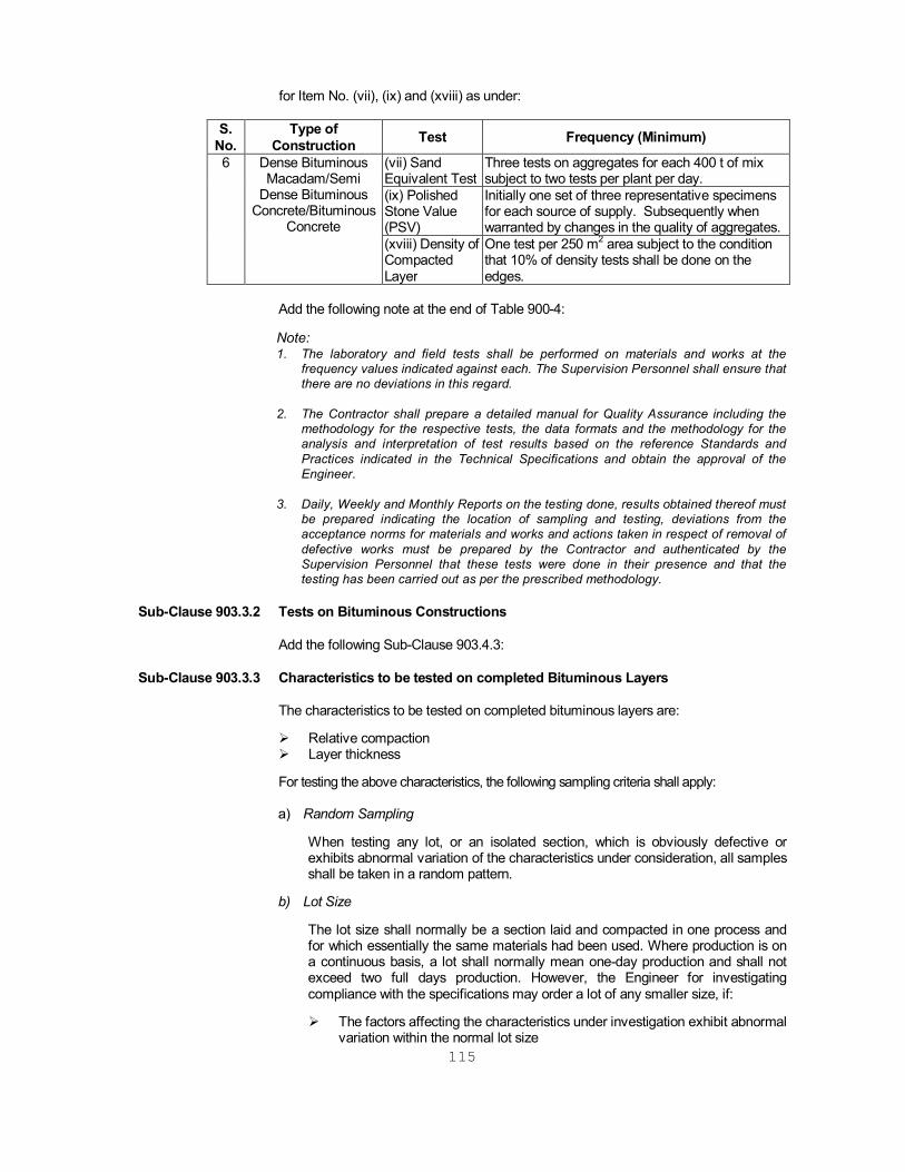
115
for Item No. (vii), (ix) and (xviii) as under:
S. No.
Type of Construction Test Frequency (Minimum)
6 Dense Bituminous Macadam/Semi
Dense Bituminous Concrete/Bituminous
Concrete
(vii) Sand Equivalent Test
Three tests on aggregates for each 400 t of mix subject to two tests per plant per day.
(ix) Polished Stone Value (PSV)
Initially one set of three representative specimens for each source of supply. Subsequently when warranted by changes in the quality of aggregates.
(xviii) Density of Compacted Layer
One test per 250 m2 area subject to the condition that 10% of density tests shall be done on the edges.
Add the following note at the end of Table 900-4:
Note: 1. The laboratory and field tests shall be performed on materials and works at the
frequency values indicated against each. The Supervision Personnel shall ensure that there are no deviations in this regard.
2. The Contractor shall prepare a detailed manual for Quality Assurance including the
methodology for the respective tests, the data formats and the methodology for the analysis and interpretation of test results based on the reference Standards and Practices indicated in the Technical Specifications and obtain the approval of the Engineer.
3. Daily, Weekly and Monthly Reports on the testing done, results obtained thereof must
be prepared indicating the location of sampling and testing, deviations from the acceptance norms for materials and works and actions taken in respect of removal of defective works must be prepared by the Contractor and authenticated by the Supervision Personnel that these tests were done in their presence and that the testing has been carried out as per the prescribed methodology.
Sub-Clause 903.3.2 Tests on Bituminous Constructions Add the following Sub-Clause 903.4.3: Sub-Clause 903.3.3 Characteristics to be tested on completed Bituminous Layers The characteristics to be tested on completed bituminous layers are:
Relative compaction Layer thickness
For testing the above characteristics, the following sampling criteria shall apply:
a) Random Sampling
When testing any lot, or an isolated section, which is obviously defective or exhibits abnormal variation of the characteristics under consideration, all samples shall be taken in a random pattern.
b) Lot Size
The lot size shall normally be a section laid and compacted in one process and for which essentially the same materials had been used. Where production is on a continuous basis, a lot shall normally mean one-day production and shall not exceed two full days production. However, the Engineer for investigating compliance with the specifications may order a lot of any smaller size, if: The factors affecting the characteristics under investigation exhibit abnormal
variation within the normal lot size
116
The area is obviously defective or of poorer quality that of the rest;
The rate of production is very high.
Sub-Clause 903.5 Quality Control Tests for Road Constructions. Sub-Clause 903.5.2 Pavement Concrete. Sub-Clause 903.5.2.1 Sampling and testing of beam and cube specimens Replace first para (“At least ………………for compliance.”) with: “One each day’s
work, at least six pairs of beams for flexural strength and six pairs of cubes for compressive strength shall be cast of concrete delivered to the paving plant as long as the total daily production is less than 300m3. For daily productions over 300m3, two additional beams and two additional cubes shall be cast of each 100m3, (or part thereof). Each pair of beams and cubes shall be from different deliveries of concrete. All specimens shall be transported in an approved manner to prevent any damage to the specimen. From each pair of beams and cubes one specimen shall be tested at 7 days and one at 28 days. The groups of beams specimens from each day’s production tested at 28 days shall be used for assessing the strength for compliance with the strength requirements. The groups of beam specimens from each day’s production tested at 7 days shall be used for early indication of the 28 days strength as described in Clause 603.3.3.2. The flexural strength test results shall prevail over compressive strength tests results for compliance.”
Replace second para (“A quality …the following manner.”) with: “Where the 28 days strength requirements are not met; or where in the opinion of
the Engineer the quality of the concrete or its compaction is suspect, the actual strength of the concrete in the slab shall be ascertained by carrying out tests on six cores cut from the concrete at such locations. The cores shall be 150 mm diameter, shall be saw cut in both ends to provide a specimen height of 300 mm 5mm and shall be tested for compressive strength. The concrete will be acceptable if:
The average compressive strength of the six cores when corrected to
28 days strength using the factors given in Table 900-5 or an age-strength relationship for the actual mix determined by the Contractor and approved by the Engineer – is at least the average compressive strength of the cores tested from the trial length, refer Clause 602.10.5.4;
None of the cores show considerable honeycombing.
Sub-Clause 903.5.2.1 Sampling the Testing of Beam and Cube Specimens. Delete sixth para (“In order test beams.”). Sub-Clause 903.5.2.1 Sampling and Testing of Beam and Cube Specimens. Delete seventh para (“The standard deviation the requirements.”) Sub-Clause 903.5.2.1 Sampling and Testing of Beam and Cube Specimens. Delete eight para (“An individual …. ..is substandard.”) Sub-Clause 903.5.2.1 Sampling and Testing of Beam and Cube Specimens
117
Add at the end of paragraph (“Beams shall……. And cubes required.”) with: “The Engineer may permit a reduction in the number of beams and cubes required when previous test results have shown satisfactory strength and when he is satisfied with the variation in quality of the mix.”
Sub-Clause 903.5.2.1 Sampling and Testing of Beam and Cube Specimens. Delete eleventh para (“The flexural…………they were taken.”). Sub-Clause 903.5.2.1 Strength Requirements. The figure 2.33 in twelfth paragraph shall be replaced by the figure 1.65. Sub-Clause 903.5.2.1 Sampling and Testing of Beam and Cube Specimens Delete thirteenth para (“Should the concrete……..flexural strength.”) Sub-Clause 903.5.2.1 Sampling and Testing of Beam and Cube Specimens. Delete fourteenth para (“The equivalent obtained from Table 900-5).” Sub-Clause 903.5.2.4 Summary of Control Tests. In Table 900-6, item 5 (I) “Strength of concrete”, change test frequency to: “On each day’s work, at least six pairs of beams and six pairs of cubes for total
daily production less than 300 m3. Two additional beams and two additional cubes for each 100 m3 (or part thereof) in excess of 300m3.”
Sub-Clause 903.5.2.4 Summary of Control Tests in Table 900-6, item S(I) “(one strength on hundred
concrete”, charge test frequency to: “As per Clause 903.5.2.1”. SECTION 1000 Materials For Structures CLAUSE 1002 SOURCE OF MATERIALS This clause shall read as follows: The Contractor shall identify the sources of materials like coarse aggregate and
sand and notify the Engineer regarding the proposed sources prior to delivery. Samples of material from the source shall be tested, in the presence of Engineer’s
representative, for conformity to specifications. It shall also be ensured that the variation in test results of different samples is within acceptable limits. If the product from the approved source proves unacceptable at any time, the Contractor shall provide new sources of acceptable material from other sources at his own expense conforming to specifications.
The manufactured items like cement, steel reinforcement, prestressing strands;
the Contractor shall intimate the Engineer details of the source (plant where the material is manufactured), testing facilities available with the manufacturer and arrangements for transport and storage of material at site. If directed by the Engineer, the Contractor shall furnish samples and test results of recently manufactured material. The Engineer, at his discretion, may require the
118
Contractor to test the materials in an independent laboratory approved by the Engineer, and furnish test certificates. The cost of these tests shall be borne by the Contractor. The sampling and test procedures shall be as laid down in Indian Standards or where these are not available as per the directions of the Engineer. Only materials from the sources approved by the Engineer shall be brought to the site. If the material from the approved sources proves unacceptable at any time, the Contractor shall provide new sources of acceptable material conforming to specifications from other sources at his own expense.
For proprietary items like bearings, expansion joints refer clause 115.1. CLAUSE 1006 CEMENT Add the following at the end of list of types of cement: f. Portland Blast Furnace Cement IS: 455
(Site blending of blast furnace slag with Ordinary Portland Cement shall not be permitted)
g. Low heat Portland Cement IS: 12600 Add following at the end of this clause.
Manufacturer’s test certificate shall be submitted to the Engineer by the contractor for every consignment of cement. The certificate should cover all the tests for chemical requirements, physical requirements and chloride content.
Independent tests of samples drawn from the consignment shall be carried out at the site laboratory or in an independent laboratory approved by the Engineer, immediately after delivery .The following properties will be tested.
Setting time Compressive strength
The cost of tests shall be borne by the contractor. In case the cement is stored beyond 90 days from date of delivery at site, the following tests shall be carried out at the site laboratory before the cement is used.
Setting time Compressive strength Lot size for independent testing of cement at site shall be the quantity received at site on any day subject to a maximum of 500 tonnes.
CLAUSE 1007 COARSE AGGREGATES Delete from the first sentence “crushed gravel …………….inert material” appearing in
4th and 5th line of Para 1. Add the following at the end of Para 2. “Costs of all tests shall be borne by the Contractor.” Add the following at the end of the Clause:

119
"Integrated stone crusher with Primary and Secondary (Cone or Impact Type) crushers shall be employed for getting proper size and grading of coarse aggregates."
The alkali aggregate reactivity should be measured and reported for getting
approval for the source aggregates at the beginning of the work using methods given in IS: 2386. The tests may be repeated if the source, or the type of rock being exploited for winning aggregates, changes.
CLAUSE 1008 SAND/FINE AGGREGATES Delete from the 3rd line the word “crushed gravel” and from the 4th line “ gravel” in Para
2. Add the following at the end of the clause: The alkali aggregate reactivity shall be measured and reported for getting approval for
the source. CLAUSE 1009 STEEL Sub-clause 1009.2 Steel for Pre-stressing Delete Clause No. 1009.2. Sub-clause 1009.3 Reinforcement/ Untensioned steel In the Table 1000.3, replace “ IS: 1786 High Yield Strength Deformed bars (HYSD)”
with “IS: 1786 Thermo mechanically treated (TMT) deformed bars”. Any other reference to “HYSD” bars in the specifications shall be read as “TMT” bars.
Delete last Para of the clause and add the following at the end of the clause. In place of existing system of CECRI (explained further in Appendix 1000-1) substitute
the following: Corrosive treatment by using Cement Polymer Composite Coating System (C.P.C.C.)
developed by CECRI, Karaikudi shall be carried out following their method and by the expert Licensee of CECRI. The brief specifications are given below:
1. The surface of the steel reinforcing bars to be cleaned by sand and or grit blasting
to the near white metal in accordance with SSPC-SP 10/ NAC No. 2-1994 and shall be completely free from rust. The prepared surface shall meet the visual standards of comparisons as in SSPC – VIS –1 or SSPC – VIS –2. The reinforcement steel first cut to required size and then sand blasting to be done.
2. The reinforcing steel is to be cut in required size and then cleaned by suitable
solvent to remove the rust. 3. After getting rust-free surface, immediately Primer Coat is to be applied on the
surface of the reinforcement by patented Primer Solution (Patent No.481/Del/93) by brush or by dipping or by spray. No surface area should be kept uncoated.
4. After application of Primer Coat, the reinforcement steel is to be kept for air-drying
for 30mts. 5. After air-drying for 30 m the Sealing Coat is to be applied by patented Cement

120
Polymer Sealing Solution (Patent No. 259/Del/92), by brush or by dipping or by spraying. No surface area should be left uncoated.
6. The Coated reinforcing steel are to be kept of air-drying for 6 hours and then can
be handled. 7. If the reinforcing bars are cut after application of coatings, then on the cut-ends
patching can be done by patented Primer Solution and patented Sealing Solution by Brush. If due to mishandling, the coating is damaged, then patching can be done by Patented Sealing Solution.
8. The Patented Primer Solution and Patented Sealing Solution must be
manufactured by the Licensee of CECRI only. 9. The applications of all the chemicals (i.e. execution of complete C.P.C.C. system)
is to be done by the Licensee of CECRI only. 10. The Patented Primer Solution & Sealing Solution and Coated bars should meet
the specifications laid down by CECRI. 11. Coated rebar shall be checked for minimum dry film thickness, uniformity of
thickness, defects such as cracks, peeling, bulging and uncoated area etc. Coating shall be tested for adhesion, bond strength, abrasion resistance, and chemical resistance as per specifications laid down by the manufacturer.
CLAUSE 1010 WATER In Para (C) the permissible limit for Chlorides (Cl) shall be read as "250 mg/lit for
structures having length more than or equal to 30 m." In case of structures of lengths 30m and below, the permissible limits of chlorides may
be increased up to 500mg/ltr. CLAUSE 1012 CONCRETE ADMIXTURES Sub-Clause 1012.1 Add the following at the end of paragraph 2 of Clause 1012.1: Admixtures shall not impair the durability of concrete; they shall not combine with the
ingredients to form harmful compounds or endanger the protection of reinforcement against corrosion. Only chloride free admixtures shall be used.
Paragraph 3 of 1012.1shall read as follows: For all admixtures being used the packing shall be marked with the name of the
supplier/manufacturer, brand name (name of product) and main effect. A certificate for the admixture in question shall be submitted. The certificate shall include the following information:
1. General
A. Chemical name of the active component in the admixture. B. Values of dry material content, ash content and relative density of
admixture, which can be used for uniformity tests.
C. Chloride ion content expressed as a percentage of weight of cement.
D. pH value and colour.

121
E. Normal side effects e.g. whether the admixture leads to air entrapment
at recommended dosage and if so to what extent.
f. Side effect when overdosed.
G. If two or more admixtures have to be used in one mix, their compatibility.
H. Increase in risk of corrosion of reinforcements and embodiments due to
the use of admixtures.
I. Latest date of test and name of test laboratory.
2. Storing A. Shelf life B. Max. & Min. allowable temperature C. Other instructions (e.g. requirements of stirring)
3. Dosage Maximum and minimum to be specified as a percentage of weight of cement. Add the following at the end of the clause: After selecting a few acceptable brands and types of admixture based on the manufacturer’s data/technical literature, independent acceptance tests should be carried out for the same using the approved combination of cement/sand/aggregates intended for use in the project. After establishing the basic acceptability using strength criteria (compression and tensile strengths) a number of trial mixes be designed using different proportions of admixtures/cement/water etc. to establish the data bank on the behavior of the admixture for the project site conditions. A spectroscopic signature of accepted product should be obtained and preserved for comparison for acceptance of the production lots. Retrial should be conducted with change in source/type of cement. Workmanship The dosage should be finalized on the basis of field trial and special mechanical devices should be used for dispensing the admixture in the batching/mixing plant. No addition of admixture after dosage is permitted (including addition in transit mixers). Manufacturer’s experts should be available for consultation/trouble-shooting of problems associated with their product. The conditions of storage, shelf life etc., as specified by the manufacturer should be strictly observed. The manufacturer’s Quality Assurance Plan during process of production should be obtained and filed for reference/record.
CLAUSE 1014 STORAGE OF MATERIALS Sub-Clause 1014.3 Aggregates The following shall be added to this Clause:

122
"Aggregates shall be stored or stockpiled in such a manner that segregation of fine and coarse sizes will be avoided and also that the various sizes will not become intermixed before proportioning. They shall be stored, stockpiled and handled in such a manner that will prevent contamination by foreign materials."
CLAUSE 1015 TESTS AND STANDARDS OF ACCEPTANCE
Add the following as Para 3:
Independent testing of pre-stressing steel shall be carried out by the Contractor for each consignment from each source at site in the laboratory approved by the Engineer before use. The tests shall be carried out for the properties as listed in clause 7.2.1 of BS- 5896:1980. These tests are in addition to the tests carried out by the Manufacturer.

123
SECTION 1100 Pile Foundations
CLAUSE 1101 DESCRIPTION
Sub-Clause 1101.2 Deleted
CLAUSE 1103 TYPE OF PILES
Deleted CLAUSE 1104 MATERIALS
Sub-Clause 1104.2 The first sentence of this clause is amended as follows:
Concrete to be used in Cast-in-situ piles shall be of grade as indicated in drawings.
Sub Clause 1104.4 Add the following as sub clause 1101.4
Deleted CLAUSE 1107 CAST IN-SITU CONCRETE PILES
Deleted.
CLAUSE 1113 PILE TESTS
Sub-Clause 1113.1 General Deleted.
CLAUSE 1118 MEASUREMENT FOR PAYMENT
Deleted.

124
CLAUSE 1119 RATE
Deleted.
SECTION 1200 Well Foundations
CLAUSE 1204 CUTTING EDGE
Deleted
CLAUSE 1205 WELL CURB
Deleted.
CLAUSE 1214 MEASUREMENTS FOR PAYMENT
Deleted.
CLAUSE 1215 RATE
Deleted.
SECTION 1500 Formwork
CLAUSE 1501 DESCRIPTION The Clause shall read as below.
The Contractor shall prepare a formwork mobilization and utilization plan and submit the plan for Engineer’s approval at least 28 days before the commencement of construction of structures. The requirement of formwork shall be worked out considering the overall construction program of all the structures to be cast in one or more stages, as specified in the drawings. The plan shall take into account the time required for erection of formwork, retention in position, stripping, and removal and subsequent use in the next and subsequent structures.
Notwithstanding Engineer’s approval of mobilization plan, if due to any reason, Contractor has to arrange additional formwork, to meet the requirements of the construction program, it shall be done by the Contractor without any extra cost to the Employer.
CLAUSE 1502 MATERIALS This Clause shall read as under: "All materials shall comply with the requirements of IRC-87. Material and components used for formwork shall be examined for damage or
excessive deterioration before use/reuse and shall be used only if found suitable after necessary repairs.
Only steel formwork shall be used. The steel used for forms shall be of such thickness
that the forms remain true to shape. All bolts should be countersunk. The use of approved internal steel ties or plastic spacers shall be permitted. Structural steel tubes used as support for forms shall have a minimum wall thickness of 4 mm."

125
CLAUSE 1504 WORKMANSHIP
Sub-Clause 1504.1 Add the following at the end of Clause 1504.1 The loading from the formwork shall be distributed to the soil or the permanent works
below (e.g. pile cap) in such a manner that any total or differential settlement are within acceptable limits. Subsoil characteristics shall be taken into account while designing the staging to avoid untoward failures. All the pipes etc. used for staging shall be free from kinks, bends etc.
CLAUSE 1506 PRECAUTIONS
Add the following as items of this clause:
Adequate support against sideway and lateral loads due to construction operations and wind shall be provided.
In case cantilevers are supported directly from the ground, the supports for cantilevers shall be removed simultaneously with main supports only after approval for the same from the Engineer.
Forms shall be rigid and of adequate section to reduce deflections. Forms shall have sufficient rigidity to resist horizontal pressures caused by flowing concrete resulting from use of superplasticisers. The formwork shall resist the lateral pressure caused due to fast rate of placement by concrete pumps.
CLAUSE 1509 RE-USE OF FORMWORK This Clause shall read as under: "After forms are stripped, all materials shall be examined for any damage and
damaged pieces, if any, shall be removed either as rejected or for rectification if possible. The materials found fit to be reused shall be thoroughly cleaned. Holes bored through sheathing for form ties shall be plugged by driving in common corks or foamed plastics. Patching plaster may also be used to fill small holes. After cleaning and before re-fixing, each formwork shall be got approved from the Engineer.
Formwork and staging shall be so used as to ensure quality of the exposed surface.
However, if in the opinion of the Engineer, any particular panel/member has become unsatisfactory for use at any stage, the same will be rejected and removed from site.
All bent steel props shall be straightened before reuse. The maximum deviation
from straightness shall not exceed 1/600 of length. However the maximum number of users shall be limited to 20 times since only steel formwork is to be used .The maximum permissible axial loads in used props shall be suitably reduced depending upon their condition.”
CLAUSE 1510 SPECIALISED FORMWORK
Replace the words ‘slip-form work’ by ‘climbing formwork’ in the first sentence of this clause.
The first sentence of Para 2 of this clause shall read as follows:
Slip forming is not permitted.
Replace the word “plywood” by “marine plywood” in the fourth paragraph of this clause.

126
SECTION 1600 Steel Reinforcement (Un-tensioned)
CLAUSE 1602 GENERAL
Paragraph 2 of Clause 1602 shall read as follows:
“Reinforcements shall be thermomechanically treated (TMT) deformed bars of grade Fe 415 conforming to IS: 1786. Only uncoated steel shall be used as reinforcement”.
CLAUSE 1604 BENDING OF REINFORCEMENT
Para 1 of Clause 1604 shall be read as follows:
The reinforcement shown on the drawings shall be considered merely symbolic representations of the shape and position and shall not be used by the Contractors to justify any deviation from the stipulated requirements. Bar bending schedules and any supplementary drawings as may be required shall be furnished by the Contractor and got approved by the Engineer before start of work. The bending schedules shall state the number, shape and length of bar and weight in respect of each type. System of bar referencing should be coherent and systematic. A separate bar bending schedule shall be prepared for auxiliary bars like spacers, chairs etc.
CLAUSE 1605 PLACING OF REINFORCEMENT
Paragraph (c) (i) of Clause 1605 shall be read as follows:
Cover blocks shall be made of concrete or cement mortar with the same durability properties as the surrounding concrete and with the same type of constituents. In visible surfaces, the cover blocks shall be of the same colour and texture as the surrounding concrete. The Contractor’s proposal for cover blocks shall be submitted to the Engineer for acceptance.
Add the following as sub Para (f) to this Clause:
Tolerances:
1. Tolerance of cover: Deviation shall not exceed + 10 mm No negative tolerance is allowed.
2. Tolerance in position: Tolerance for deviation from the positions shown in the drawings shall not exceed the following:
Structural depth d (mm) Tolerance (mm)
d < 1000 <10
1000 < d < 2000 < 0.01d
2000 < d < 20
CLAUSE 1606 BAR SPLICES
Sub-Clause 1606.1 First sentence of Clause 1606.1 shall read as follows:
To the extent possible, all reinforcement shall be furnished in full lengths as indicated in drawings.

127
Add the following as paragraph 2 of Clause 1606.1:
The location of joints in continuous reinforcing bars, not shown in drawings, shall be submitted to the Engineer for acceptance. If nothing contrary has been specified, the number of bars to be joined in any cross-section shall not exceed one-third of the total.
Sub-Clause 1606.2 Welding
Sub-Clause 1606.2.1 Add the following at the end of the paragraph.
In prestressed concrete members, when welding of untensioned reinforcement is permitted by the Engineer, it shall be carried out before insertion of the prestressing tendons/sheathing.
CLAUSE 1607 TESTING AND ACCEPTANCE
Add the following as the last paragraph of Clause 1607:
Manufacturer’s test certificate regarding compliance with Indian Standards for each lot of steel shall be obtained and submitted to the Engineer. If required by the Engineer, the Contractor shall carry out confirmatory tests in the presence of a person approved by the Engineer. Cost of these tests shall be borne by the Contractor. The sampling and testing procedure shall be as laid down in IS: 1786-1985. However if any test piece selected from a lot fails, no re – testing shall be done and the lot rejected.
SECTION 1700 Structural Concrete CLAUSE 1703 GRADES OF CONCRETE Add the following at the end of this Clause: The concrete mixes leaner than M15 shall be called as nominal mix concrete.
“Nominal mix concrete is for which, concrete is not to be designed by tests and in which the proportions of materials are in accordance with the drawing and the specification clause mentioned below:
i) All the materials for this concrete shall conform to section 1000 of MORT&H. ii) Minimum cement content and maximum water cement ratio for above said
nominal mix concrete shall conform to clause 1703.2 Table 1700-3(A) of MORT&H.
iii) Mixing of above said nominal mix concrete shall conform to Clause 1708 of
MORT&H.
iv) Transporting, Placing and Compaction of above said nominal mix concrete should conform to clause 1709 of MORT&H”.
CLAUSE 1704 PROPORTIONING OF CONCRETE
Add the following at the end of this Clause: “In proportioning concrete, the quantity of both cement and aggregate shall be
determined by weight. Where the weight of cement is determined by accepting the manufacturer’s weight per bag, a reasonable number of bags shall be weighed

128
separately to check the net weight. Where cement is weighed from bulk stock at site and not by bag, it shall be weighed separately from the aggregates. Water shall either be measured by volume in calibrated tanks or weighed. All measuring equipment shall be maintained in a clean and serviceable condition. Their accuracy shall be periodically checked.
It is most important to keep the specified water-cement ratio constant and at its correct
value. To this end, moisture content in both fine and coarse aggregates shall be determined as frequently as possible; frequency for a given job being determined by the Engineer according to the weather conditions. The amount of mixing water shall then be adjusted to compensate for variations in the moisture content. The determination of moisture content in the aggregates shall be done as per IS: 2386 (Part III). Suitable adjustments shall also be made in the weight of aggregates to allow for the variation in weight of aggregates due to variation in their moisture content.”
Sub-Clause 1704.4 Additional Requirements In Para (a) substitute "0.06%" for "0.1%"; "0.06%" for "0.2%; and “0.1%" for "0.3% for
the three items respectively. Sub-Clause 1704.6 Add the following as clause 1704.6: Materials for pumped concrete: Materials for pumped concrete shall be batched consistently and uniformly.
Maximum size of aggregate shall not exceed one-third of the internal diameter of the pipe.
Grading of aggregate shall be continuous and shall have sufficient ultra fine
materials (materials finer than 0.25 mm). Proportion of fine aggregates passing through 0.25mm shall be between 15 and 30% and that passing through 0.125 mm sieve shall not be less than 5% of the total volume of aggregate. Admixtures to increase workability can be added. When pumping long distances and in hot weather set-retarding admixtures can be used. Fluid mixes can be pumped satisfactorily after adding palsticisers and super plasticisers. Suitability of such concrete shall be verified by trial mixes and by performing pumping test.
CLAUSE 1705 ADMIXTURES This Clause shall read as under: "Duly tested admixtures/additives conforming to IS: 6925 and IS: 9103 (without
replacement of cement) may be used subject to satisfactory proven use, with the approval of the Engineer. Admixtures generating Hydrogen or Nitrogen and containing chlorides, nitrates, sulphides, sulphates and any other material liable to affect the steel or concrete shall not be permitted.
The general requirements, physical and chemical requirements shall be as per Clause
1012."

129
CLAUSE 1706 SIZE OF COARSE AGGREEGATE Table 1700-7 shall be modified as given below: CLAUSE 1707 EQUIPMENT Para 1 of this Clause shall read as under: “Unless specified otherwise, equipment for production, transportation and
compaction of concrete shall be as under:
a) For production of concrete: Batching and mixing of the concrete shall be done in a concrete batching and mixing plant fully automatic of a minimum capacity of 40 cum/hour. The plant shall be approved by the Engineer.”
Paragraph 3 of this clause shall read as follows: “The accuracy of measuring devices shall fall within the following limits: Measurement of Cement + 1% of the quantity of cement in each batch. Measurement of Water + 1% of the quantity of water in each batch. Measurement of Aggregate + 2% of the quantity of Aggregate in each batch. Measurement of Admixture + 1% of the quantity of Admixture in each batch.
Components Maximum nominal size of Coarse aggregate (mm)
a. RCC Well Curb. b. RCC / PCC well steining, PCC below
foundations and approach slab, annular filling around foundations.
c. Well cap or pile cap; solid wall type
abutments, piers, median walls, splayed wing walls and their foundations.
d. RCC works in T-beam and slab / solid slab /
voided slab and box girder superstructure, wearing coat, kerb, crash barrier, approach slab, dirt walls, coping on masonry wing walls, hollow abutments and piers, pier / abutment caps, pedestals, dirt walls, piles, all components of counterfort type abutments, columns, cantilever return walls etc.
e. All PSC works f. Any other item
20
40
40
20
20
As specified by the Engineer

130
Paragraph 3(b) & 3(c) shall remain unchanged. Add the following paragraph at the end of the clause: Batching, mixing transportation and placing concrete. Once the concreting of a section is started, it has to be completed as a continuous
operation. Before starting an important placement, the Contractor shall submit to the Engineer an equipment list to ensure that sufficient equipment is available for batching, mixing, transporting and placing concrete and once the concreting of a section is started, it can be completed as a continuous operation within a reasonable time.
CLAUSE 1709 TRANSPORTING, PLACING AND COMPACTION OF CONCRETE Add the following paragraph at the end of the clause: For Placing Concrete with Pumps: Pipe Lines from the pump to the pacing area
should be laid out with a minimum of bends. For large concrete placements standby pumps shall be available. Suitable valves (air release valves shutoff, valves etc.) shall be provided as per the site needs. The pumping of concrete shall be preceded by a priming mix to lubricate the pump and pipeline. A rich mix of creamy consistency shall be required for lubricating the pipelines; continuous pumping shall be done to the extent possible. After concrete has been placed the lines all related equipment shall be cleaned immediately. A plug sponge ball shall be inserted in the end near the pump and shall be forced through the line by either water or air pressure. Pipes for pumping should not be made from materials, which can harm concrete; aluminium alloy pipelines shall not be used.
CLAUSE 1710 CONSTRUCTION JOINT (Refer Appendix 1700/1, Preparation of the Surface
of the Joint) In the first paragraph, add after the words “the surface shall be roughened” the
words “the coarse aggregate shall be made visible to a depth of 5 mm to 10 mm”. In the third paragraph under the heading “Preparation of the Surface of the Joint”
add the following at the end of paragraph. “Bush hammering is not permitted since it loosens the coarse aggregate and
results in extensive micro cracks.” Concreting of Joints: Under the heading “Concreting of Joints”, add the following at the end of sub-Para
3”. “At vertical construction joints, a fine mesh on the inner surface of the stopping
board shall be placed, if directed by the Engineer, the facilitate removal of laitance.”
CLAUSE 1712 ADVERSE WEATHER CONDITIONS Sub -Clause 1712.2 Hot Weather Conditions Add the following at the end of paragraph 1 of the above clause: Where the Contractor proposes to use ice to cool the concrete or mixing water or
any of the ingredients, the Contractor shall provide a refrigeration plant to avoid

131
use of contaminated ice. Placement of concrete shall not be permitted when day temperature exceeds
40oC. CLAUSE 1713 PROTECTION AND CURING Sub-Clause 1713.1 Water Curing Add the following at the end of Para I: Water sprinklers or perforated pipes shall be used for curing of concrete for all major
bridges, ROB’s and grade separators. Such arrangement must be in place & tested before concreting for its proper functioning and shall be maintained for a minimum period of 14 days after concreting.
Approved concrete curing compounds should be preferred where water curing cannot
be done reliably. CLAUSE 1715 TOLERANCES Add the following at the end of Clause: “In the absence of any information in drawings or specifications, for particular
cases, the following limitations shall apply.
Dimension (mm) ‘a’
Tolerances (mm) ‘δa=(a nominal – a actual)’
a < 200 200 < a < 2000
2000 < a
| δ a | < 5 |δ a | < 3.5 + 0.0075a |δ a | < 16.5 + 0.001a
CLAUSE 1719 COATING OF EPOXY BASED PROTECTIVE PAINT DEVELOPED BY CECRI
KARAIKUDI FOR ANTICORROSIVE TREATMENT ON EXTERNAL SURFACE OF SUPERSTRUCTURE UNDER MARINE CONDITIONS
Areas of the concrete shall be coated with a multicoat epoxy polyamide system developed by CECRI, Karaikudi consisting of a red oxide polyamide epoxy based primer at a DFT of 50 microns, micaceous iron oxide polyamide epoxy based middle coat at a DFT of 110 microns, Titanium dioxide Polyamide-epoxy based topcoat at a DFT of 100 microns. The finished coat shall be aliphatic polyurethane based and shall be applied at a DFT of not less than 40 microns capable of providing ultraviolet solar radiation resistance. The total DFT of the protection system shall not be less than 300 microns. The cured film shall provide a smooth surface finish. The overall success in terms of performance & durability of coating applied to Cementatious substrates is greatly dependent on quality of surface preparation. Efflorescence / hydroscopic salts or moisture present in substrates should be removed/expelled by suitably methods including sand blasting if necessary. Surface for application should be free from loose particles and must be remove by mechanical means to ensure bonding of protective coating system. It is strongly recommended that mechanical methods such as shot/grit blasting be deployed to ensure the efficiency of coating through subsequent development of bond with the substrate. Surface such as concrete, plasters etc., to be coated must be totally clean, dry, structurally sound and free from contaminants such as oil, grease, shutter releasing agents and curing membrane. The substrate should be at least 28 days
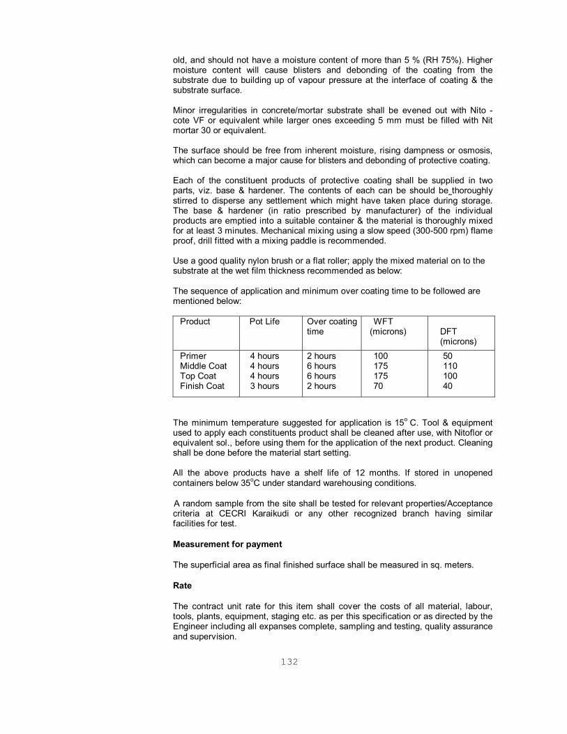
132
old, and should not have a moisture content of more than 5 % (RH 75%). Higher moisture content will cause blisters and debonding of the coating from the substrate due to building up of vapour pressure at the interface of coating & the substrate surface. Minor irregularities in concrete/mortar substrate shall be evened out with Nito - cote VF or equivalent while larger ones exceeding 5 mm must be filled with Nit mortar 30 or equivalent. The surface should be free from inherent moisture, rising dampness or osmosis, which can become a major cause for blisters and debonding of protective coating. Each of the constituent products of protective coating shall be supplied in two parts, viz. base & hardener. The contents of each can be should be thoroughly stirred to disperse any settlement which might have taken place during storage. The base & hardener (in ratio prescribed by manufacturer) of the individual products are emptied into a suitable container & the material is thoroughly mixed for at least 3 minutes. Mechanical mixing using a slow speed (300-500 rpm) flame proof, drill fitted with a mixing paddle is recommended. Use a good quality nylon brush or a flat roller; apply the mixed material on to the substrate at the wet film thickness recommended as below: The sequence of application and minimum over coating time to be followed are mentioned below:
Product
Pot Life
Over coating time
WFT (microns)
DFT (microns)
Primer Middle Coat Top Coat Finish Coat
4 hours 4 hours 4 hours 3 hours
2 hours 6 hours 6 hours 2 hours
100 175 175 70
50 110 100 40
The minimum temperature suggested for application is 15o C. Tool & equipment used to apply each constituents product shall be cleaned after use, with Nitoflor or equivalent sol., before using them for the application of the next product. Cleaning shall be done before the material start setting. All the above products have a shelf life of 12 months. If stored in unopened containers below 35oC under standard warehousing conditions.
A random sample from the site shall be tested for relevant properties/Acceptance criteria at CECRI Karaikudi or any other recognized branch having similar facilities for test.
Measurement for payment
The superficial area as final finished surface shall be measured in sq. meters.
Rate
The contract unit rate for this item shall cover the costs of all material, labour, tools, plants, equipment, staging etc. as per this specification or as directed by the Engineer including all expanses complete, sampling and testing, quality assurance and supervision.
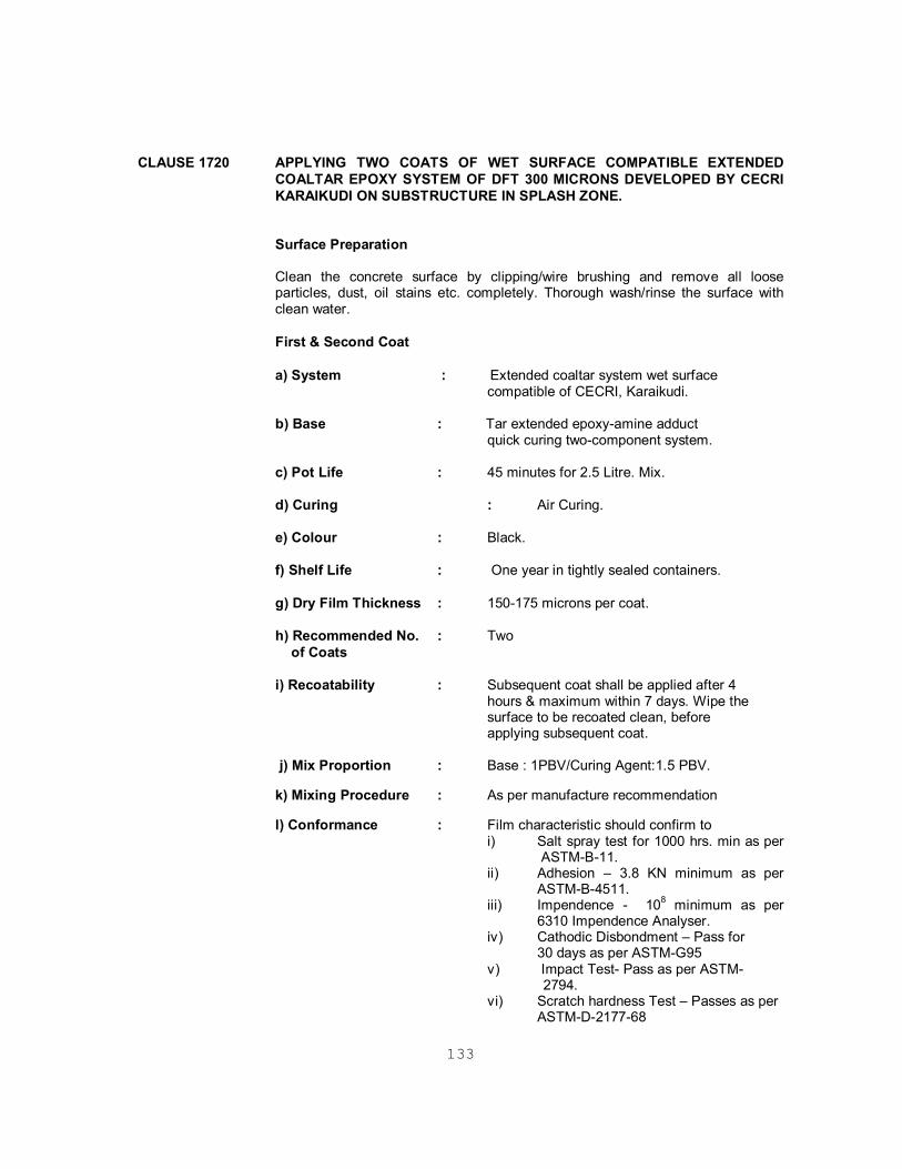
133
CLAUSE 1720 APPLYING TWO COATS OF WET SURFACE COMPATIBLE EXTENDED
COALTAR EPOXY SYSTEM OF DFT 300 MICRONS DEVELOPED BY CECRI KARAIKUDI ON SUBSTRUCTURE IN SPLASH ZONE.
Surface Preparation Clean the concrete surface by clipping/wire brushing and remove all loose particles, dust, oil stains etc. completely. Thorough wash/rinse the surface with clean water. First & Second Coat a) System : Extended coaltar system wet surface compatible of CECRI, Karaikudi. b) Base : Tar extended epoxy-amine adduct
quick curing two-component system.
c) Pot Life : 45 minutes for 2.5 Litre. Mix.
d) Curing : Air Curing.
e) Colour : Black. f) Shelf Life : One year in tightly sealed containers. g) Dry Film Thickness : 150-175 microns per coat. h) Recommended No. : Two of Coats
i) Recoatability : Subsequent coat shall be applied after 4
hours & maximum within 7 days. Wipe the surface to be recoated clean, before
applying subsequent coat. j) Mix Proportion : Base : 1PBV/Curing Agent:1.5 PBV. k) Mixing Procedure : As per manufacture recommendation l) Conformance : Film characteristic should confirm to
i) Salt spray test for 1000 hrs. min as per ASTM-B-11.
ii) Adhesion – 3.8 KN minimum as per ASTM-B-4511.
iii) Impendence - 108 minimum as per 6310 Impendence Analyser.
iv) Cathodic Disbondment – Pass for 30 days as per ASTM-G95
v) Impact Test- Pass as per ASTM- 2794. vi) Scratch hardness Test – Passes as per
ASTM-D-2177-68

134
m) Quality Assurance : A random sample from the site shall be tested for relevant guideline properties/Acceptance criteria at CECERI Karaikudi / CBRI Roorkee /SERC Chennai.
Measurement for payment
The superficial area as final finished surface shall be measured in sq. meters.
Rate
The contract unit rate for this item shall cover the costs of all material, labour, tools, plants, equipment, staging etc. as per this specification or as directed by the Engineer including all expenses complete, sampling and testing, quality assurance and supervision.
SECTION 1800 Pre-stressing
Deleted
CLAUSE 1803 TESTING OF PRESTRESSING STEEL AND ANCHORAGE
Deleted.
CLAUSE 1806 TENSIONING EQUIPMENT
Deleted.
CLAUSE 1807 POST TENSIONING
Deleted.
CLAUSE1808 GROUTING OF PRE-STRESSED TENDONS Deleted. CLAUSE 1815 RATE Deleted. CLAUSE 1816 JOINTS IN CONSTRUCTION WITH PRE-CAST-UNIT Deleted.
SECTION 2000 Bearings
Deleted SECTION 2100 Open Foundations CLAUSE 2106 TOLERANCES Reference to Tolerance shall be made to Clause 1715. SECTION 2200 Sub-Structure CLAUSE 2204 PIERS AND ABUTMENTS Para 2 is replaced as follows:
135
Slip forming will not be allowed. Add the following paragraph at the end of clause: “Where necessary suitable cofferdams or other means shall be provided to
exclude water from the construction area. The Contractor shall provide necessary pumping equipment for dewatering areas”.
Sub-Clause 2210 Rate This Clause shall read as follows: “The contract rate for masonry, concrete and reinforcement in substructure shall
include all works as given in respective sections and cover the cost of incidental items like providing cofferdams, dewatering, providing special formwork, where necessary, and all other items for furnishing and providing substructure as mentioned in this section.”
The necessary material (thermocole, bituminous fibrous board or equivalent
material) and labour, tools etc. required for maintaining 20 / 40 mm gap between faces of various structures (old / new) wherever required / as shown in drawing shall be incidental to work and shall not be measured / paid separately.
SECTION 2500 River Training Work And Protection Work Deleted.
SECTION 2600 Expansion Joints Deleted.
SECTION 2700 Wearing Coat And Appurtenances CLAUSE 2703 RAILINGS AND PARAPETS Sub-Clause 2703.3 Cast-in-Situ Railings and parapets Last sentence of paragraph 3 shall be replaced by the following. “Location of construction joints shall be determined in advance and approved by
Engineer.” Sub-Clause 2703.5 Concrete crash barrier bridges
Sub-Clause 2703.5.1 General This work shall consist of construction, provision and installation of concrete crash
barrier on the bridge deck / approach slab at locations and of dimensions as shown on the drawings or as directed by the Engineer.
Sub-Clause 2703.5.2 Materials All materials shall conform to Section 1000-Materials for Structures as applicable,
and relevant Clauses in Section 1600 shall govern the steel reinforcement. The concrete barriers shall be constructed either by the “cast-in-place with fixed forms” method or the “extrusion or slip form” method or a combination thereof at the

136
Contractor’s option with the approval of the Engineer. Where “extrusion or slip form” method is adopted, full details of the method and literature shall be furnished.
Grade of concrete for Crash barriers on deck slab, approach slab etc. shall be M40, whereas concrete grade of M 25 shall be used for crash barriers on right return walls, retaining walls etc.
An expansion joint with Polysulphide Joint sealants and bituminous fiberboard shall be provided in the crash barriers at the location of expansion joints/ gaps on the bridge, approaches etc.
Sub-Clause 2705.3.3 Construction Operations The location of crash barrier shall be strictly adhered to as shown on the drawing
and as directed by the Engineer. Concrete crash barriers shall present a smooth, uniform appearance in their final position, conforming to the horizontal and vertical lines shown on the plans or as ordered by the Engineer and shall be free of lumps, sags or other irregularities. The top and exposed faces of the barriers shall conform to the specified tolerances, as defined in Clause 809.4, when tested with 3 m straight edge, laid on the surface.
Sub-Clause 2703.5.4 Tolerance
The overall horizontal alignment of crash barrier and rails shall not depart from the road alignment by more than + 30 mm, nor deviate in any two successive lengths from straight by more than 6 mm and the faces shall not vary more than 12 mm from the edge of a 3 m straight edge. Barriers shall be at the specified height as shown in the plans above the edge of the nearest adjacent carriageway or shoulder, within a tolerance of + 30 mm.
Sub-Clause 2703.5.5 Measurements for Payment
All barriers will be measured in cubic metres of concrete completed for the barriers including approach and departure ends. The steel rails on the top of crash barrier shall be measured and paid separately. The sealing of opening in crash barrier at expansion joints with polysulphide rubber joint sealant and bituminous fibreboard as per sub- clause 2703.6 shall be incidental to work.
Sub-Clause 2703.5.6 Rate
The Contract unit rate shall include full compensation for furnishing all labour,
materials, tools, equipment and incidental costs necessary for doing all the work involved in constructing the concrete barrier complete in place in all respects as per these Specifications.
Sub-Clause 2703.6 POLYSULPHIDE RUBBER JOINT SEALANT
Polysulphide Joint sealants with bituminous fiberboard shall be provided in the Expansion Joints/ gaps in Crash Barriers.
Before application it shall be ensured that the top of the bituminous fiberboard and the concrete faces are dry, sound, free from dirt, grease and other loose foreign matter. A thin coat of primer shall be applied on concrete faces with a brush to air dry before applying sealant. The components of the sealant i.e. base and hardener shall be mixed in a slow speed mixed sealant till uniform color is obtained. Placement of the mechanical mixer shall be done with either cartridge

137
or fully enclosed gun barrels within 30 minute of mixing. Manufacturer’s recommendation shall be followed.
The sealing compound shall be two packs, low modulus of elasticity Polysulphide elastomer having bituminous ingredients such as Cico T-680 or equivalent with following properties of the cured compound.
Tensile strength - 0.4 MPa 10%
Modulus of elasticity - At 100% elongation: 0.15 MPa
Elongation - Elongation at break 550%
Hardness - Shore ‘A’ hardness 22 3 @ 25°C
Operating temperature - -20°C to + 80°C
Shrinkage - Less than 1%
Permanent dynamic - 25%
Movement capability
Polysulphide material shall be approved by the Engineer prior to procurement . Measurements for Payments: Cost for providing Polysulphide Joint sealants and bituminous fiberboard in the
Expansion Joints in Crash Barriers shall be deemed to be included in the unit rate of Crash Barrier and shall not be measured separately.
CLAUSE 2704 Provision of approach slab shall be in accordance with “Guide lines regarding
approach slab for bridges” given in MOST circular no. RW/NH-34015/2/86-S&R dated 22 June 1994.
CLAUSE 2706 WEEP HOLE This clause shall read as under: “Weep holes shall be provided in solid plain concrete/reinforced concrete/brick
masonry abutments, wing walls, return walls as shown in the drawing or as directed by the Engineer to drive moisture from the back filling. Weep holes shall be provided with 100 mm dia A.C. pipe and shall extend through the full width of concrete with slope of about 1 vertical: 20 horizontal towards the draining face.
The spacing of weep holes shall generally be 1m in either direction or as shown in the
drawing with the lowest at about 150 mm above the low water level or ground level whichever is higher or as directed by the Engineer."
CLAUSE 2709 RATE The second paragraph shall be read follows: “The contract unit rate of parapets and railings shall include the cost of all labour,
materials tools and plant required for completing the unit in accordance with specifications”.
Add at the end of Para 2: The contract unit rate for approach slab shall include cost of providing and laying
in position bitumen joint filler with joint sealing compound in the 20 thick gap

138
between dirt wall and approach slab.
139
SECTION 2800 Repair of Structures CLAUSE 2809 DISMANTLING OF EXISTING WEARING COAT, EXPANSION JOINTS AND
DRAINAGE SPOUTS
Sub-Clause 2809.1 Add the following at the end of Clause 2809.1
The existing wearing coat, concrete as well as bituminous overlay, shall be removed for the entire length including approach slab for all minor bridges with solid slab superstructure. Only damaged portion of wearing coat shall be removed for major bridges and minor bridges with T-Beam and slab superstructure.
Sub-Clause 2809.2 This Clause shall read as follows:
The removal operations shall be carried out mechanically using pavement breakers and compressors. Removal shall be done carefully to avoid damage to any part of the existing structure. In delicate locations for example around spouts, removal shall be done by manual methods. After removal, the concrete deck surface shall be closely inspected for identifying any distress such as cracks, pockets of loose or honeycombed concrete etc. The deck surface shall be thoroughly cleaned with special efforts to remove any loose material. Expansion joints and spouts shall be removed carefully so that deck concrete is not damaged.
Sub-Clause 2809.3 Add the following at the end of clause 2809.3
Dismantled material shall not be stacked on the deck nor shall it be thrown below the bridge. It shall be neatly piled at points designated by the Engineer with all lifts and lead upto 1000m. Materials, which can be used or auctioned, shall be stored in neat piles at locations designated by Engineer with all lifts and lead upto 1000m.
New clauses 2811 to 2829 shall be added after Clause 2810 as given below and existing clauses 2811, 2812 and 2813 shall be renumbered as 2830, 2831 and 2832.
CLAUSE 2811 DISMANTLING OF EXISTING RAILING, KERBS, FOOTPATH SLABS, PART or COMPLETE DECK SLAB, APPROACH SLABS AND DAMAGED CONCRETE IN WING WALLS/RETURNS, PIERS AND ABUTMENTS, RCC/BRICK MASONARY, ENCLOSURES OF BEARINGS
Railing, kerbs, footpath slabs, approach slabs, part or complete deck slabs and damaged concrete in wing walls / returns, piers and abutments, RCC/Brick masonry exclusive of bearings of the existing structures shall be dismantled as shown in drawings or as directed by the Engineer.
The work shall be executed in accordance with MoRT&H Specifications Section 200 clause 202. All damaged concrete in wing walls; returns, piers and abutments shall be thoroughly inspected to identify the extent of dismantling. The decision of Engineer regarding extent of dismantling shall be final. Care shall be taken to avoid damage to any part of the existing structure. Dismantling work for railing and kerbs shall be done carefully such that the existing reinforcement, which will project into the new work, is not damaged or lost. Reinforcement shall be cleaned thoroughly.
Dismantled material shall not be stacked on the deck nor shall it be thrown below the bridge. It shall be neatly piled at points designated by the Engineer with all lifts and lead upto 1000m. Materials, which can be used or auctioned, shall be stored
140
in neat piles at locations designated by Engineer with all lifts and lead upto 1000m.
Water shall be sprayed to reduce dust while dismantling work is in progress. Dismantling work shall not be carried out at night, during storms or heavy rain.
Goggles and gas masks shall be worn at the time of dismantling. Leather gloves shall be worn by the workers. Screens made of G.I. sheets shall be placed wherever necessary to prevent the flying pieces from injuring the workers.
Damage caused to any component of the bridge structure during removal operations shall be restored by the Contractor at his cost. The service lines, if any, shall be disconnected/diverted before dismantling work commences.
CLAUSE 2812 DISMANTLING OF EXISTING DAMAGED BRICK / COURSE RUBBLE MASONRY IN WING WALLS / RETURNS, PARAPETS etc.
Damaged brick/ course rubble masonry in wing walls / returns and all brick / course rubble masonry parapets shall be dismantled as shown in drawings or as directed by the Engineer.
The work shall be executed in accordance with MoRT&H Specification Section 200 Clause 202. Damaged brick / course rubble masonry in wing walls / return shall be thoroughly inspected to identify the extent of dismantling. The decision of the Engineer regarding extent of dismantling shall be final. Care shall be taken to avoid damage to any part of the existing structure.
Dismantled material shall not be stacked on the deck nor shall it be thrown below the bridge. It shall be neatly piled at points designate by the Engineer with all lifts and lead upto 1000m. Materials, which can be used or auctioned, shall be stored in neat piles at locations designated by Engineer with all lifts and lead upto 1000m.
Leather gloves shall be worn by the workers. Screens made of G.I. Sheets shall be placed wherever necessary to prevent the flying pieces from injuring the workers.
Damage caused to any component of the bridge structure during removal operations shall be restored by the Contractor at his cost.
CLAUSE 2813 DISMANTLING OF EXISTING SPLAYED WING WALL FOR CONSTRUCTION OF ADJACENT 2 LANE BRIDGE - a) BRICK COURSE RUBBLE MASONRY b) CONCRETE
Existing Brick / course rubble masonry / concrete wing wall shall be dismantled for
construction of adjacent 2 lane bridge as shown in drawings or as directed by Engineer.
The work shall be executed in accordance with MoRT&H Specifications section
200 clause 202 only portions which interfere with the construction of wing walls/return/median wall of adjacent 2-lane bridge shall be dismantled. The decision of the Engineer regarding extent of dismantling shall be final.
During dismantling all precautions shall be taken to prevent failure of retained
earth of the approaches. Dismantled material shall not be stacked on the deck nor shall it be thrown below
the bridge. It shall be neatly piled at points designated by the Engineer with all lifts and lead up to 1000m. Materials, which can be used or auctioned, shall be stored

141
in neat piles at locations designated by Engineer with all lifts and lead up to 1000m.
Goggles and gas masks shall be worn at the time of dismantling. Leather gloves shall be worn by the workers. Screens made of G.I. Sheets shall be placed wherever necessary to prevent the flying pieces from injuring the workers.
Damage caused to any component of the bridge structure during removal
operations shall be restored by the Contractor at his cost.
CLAUSE 2814 FIXING DOWEL BARS IN DECK SLAB AND GROUTING WITH NON-SHRINK FREE FLOW CEMENT GROUT
20 mm dia. holes, 150 mm deep, shall be drilled in existing slab at locations shown in the drawings.
Holes shall be drilled vertically using rotary drill machines. Care shall be taken that the holes are drilled vertical and the deck concrete is not damaged. It shall be ensured that buried reinforcement of the deck is not damaged due to drilling by avoiding locations above reinforcement. Rebar detector shall be used for this purpose. 16/12 mm dia. dowel bars shall be inserted in the hole and kept in undisturbed position with appropriate fixture. The annular space shall be filled by non-shrink free flow cement grout.
Measurement for Payment
Measurement shall be made for number dowel bars to be fixed in deck slab. The reinforcement steel shall be measured separately.
Rate
Contract unit rate for each dowel bar fixed in deck slab shall cover cost of all material, labour, tools, plant and equipment required for drilling of holes in deck slab, non shrink cement grout etc. but excluding cost of reinforcement steel.
CLAUSE 2815 RAILING/PARAPETS
Cast-in-situ railings/parapets shall be constructed in accordance with the requirements of structural concrete Section 1700. The reinforcement shall conform to Section 1600. The formwork shall conform to Section 1500. The work in general shall conform to Section 2700 clause 2703.
The reinforcement of the railings/parapets shall be welded with the existing reinforcement of the deck slab and with the dowel bars as shown in the drawings or as directed by the Engineer.
In case there are no old dowel bars fresh dowel bars shall be fixed into deck slab as per clause 2814.
CLAUSE 2816 REPAIR OF CORRODED REINFORCEMENT
Repair of corroded reinforcement (where corrosion has reduced the diameter of the bar by more than 20%) shall be done by providing new reinforcement, which is either welded or firmly secured with the old reinforcement.
1 Material
Steel which is to be used as additional reinforcement where the diameter of

142
existing main longitudinal reinforcement has been reduced to 80% of the original, should satisfy the requirements of IS: 226-1975 or IS: 1786-1976. However, the BRC fabric or weld mesh, which are to replace/strengthen the corroded stirrups, or tie bars, should be from reputed manufacturers.
2 Repairing Procedure
The exposed reinforcement showing signs of deterioration by corrosion shall be cleaned by grit blasting.
When corrosion products have been removed, the diameter of the reinforcement shall be measured. If the diameter of the reinforcement is found to be reduced to 80% of the original, then additional reinforcement of equivalent diameter free from rust shall be firmly secured with the old reinforcement, preferably by welding, if existing reinforcement can be welded or with a lap of at least 40 times the dia of the bar.
CLAUSE 2817 PROVIDING AND FIXING DRAINAGE SPOUT INCLUDING SEALING WITH NON-SHRINK FREE FLOW CEMENT GROUT.
Deleted.
CLAUSE 2818 REPAIR TO LEACHED, HONEYCOMBED, SPALLED CONCRETE
Leached, honeycombed, spalled concrete (area of damage less than 0.5 m2) shall be repaired with average 50m average thick PMC mortar in two or more layers with a bond coat of PMC slurry between two successive layers.
All loose concrete shall be chipped off with a chipping machine so that loose layers of concrete are removed exposing the reinforcement. All loose concrete sticking with the reinforcement shall be removed. Where reinforcement bars are already exposed, the chipping shall continue so as to expose half the diameter, prior to further treatment. The concrete surface shall be thoroughly cleaned with wire brush and oil free air blast. Where the damaged areas are large, sand blasting should be done to clean the reinforcement and the surrounding concrete. If reinforcement is seen, the same shall also be cleaned thoroughly. The reinforcement shall be coated with PMC slurry within one hour of cleaning to prevent rusting. The PMC shall be brush applied on the cleaned reinforcement ensuring that full surface area is covered in accordance with the manufacturers recommendation.
Before applying PMC repair mortar the prepared concrete substrata shall be thoroughly soaked with clean water. Free surface water shall be removed before priming. The substrate shall be primed with PMC slurry.
The specifications for polymer modified cementatious (PMC) mortar / debonding slurry are as under:
The anti corrosive polymer latex, which is to be used should consist of water based QA-Acrylic polymer incorporated with non-alcoholic bipolar corrosion inhibitor .The polymer to be used shall be MONOBOND-2000 or equivalent.
Colour: Milky white liquid
Solid content: The polymer solid content shall be 36 1 percent. The particles shall be of nearly spherical shape with a diameter of 0.350.05 micrometer. The manufacture shall certify the above requirements about solid content & grain size. In order to keep control over the quality, the manufacture shall provide infrared

143
absorption spectrum analysis for the material to be supplied by them. Mixing proportion: Anti-corrosive polymer modified mortar o Cement –100 parts by weight o Monobond-2000 - 40 parts by weight o Mix no. 10 Silica sand –300 parts by weight The sand, which is to be used for constituting the PMC repair mortar, should be silica sand as the basic material, which is categorized in two groups.
a) Coarse Silica and b) Fine Silica
The grading of the above groups should follow the limits provide below.
Quartz sand mix No. 10
I.S. Sieve No.
Percentage passing by weight
10 mm 100 4.75 mm 100 2.36 mm 100 1.18 mm 85 - 90 600 microns 45 - 55 300 microns 15 - 20 150 microns 5 - 10 75 microns 0 - 3
In the event of using local sand, the sand to be used must satisfy the limits of deleterious materials & the requirements of soundness as given in Cl 3.2.1 & Cl 3.6 respectively of IS: 383, confirmatory test shall be conducted by the contractor and sample kept for comparison by the engineer. Curing: Air-corrosive polymer modified mortar curing procedure outline apply to normal weather conditions. Under hot weather, take precautions to avoid drying. PMC work should be carried out at a temperature below 40o C. Under unusual condition weather conditions e.g. high humidity and / or high wind velocity or imposed constraints special curing procedure shall be followed for which approval shall be obtained from the engineer. Anti-drying shall be considered to be taken place only during favourable uninterrupted weather condition existing throughout the existing recommend drying period. Some judgments shall be made in this respect & if conditions are deemed unfavourable for drying to occur, then drying must be prolonged for the full recommend period after weather clears.
As PMC work proceeds, precautions shall be taken to prevent rapid drying of the PMC repair mortar. This is usually accomplished by covering the filled surfaces with an impermeable sheet shortly after the work has been done.
The sheet shall be kept in place until further work is carried out over the mortar or in case where the mortar is likely to be disturbed the sheet shall be kept in place

144
for 24 hours.
No foot traffic for further work shall be allowed over mortar until 12 hours for the time of the completion of work. Curing compound may also be used as curing membrane. Care shall be taken to ensure complete covering particularly around the interface with the host concrete. For the first day the repaired concrete patch shall be protected from harsh environment by laying a polythene sheet over it, lapping down the edges. Mixing PMC Methods of Mortar mixing To mix PMC, it is necessary to have the following items: o A suitable sized non-ferrous mixing container preferably plastic. o A high-speed drill with mixing paddles. o Promark batching containers for measuring out components to be mixed. Pour all the liquid polymers latex into mixing container. After shaking the latex to disperse the solid uniformly throughout the liquid before use. Begin mechanical mixing & while doing so, slowly add the dry components, i.e. cement & sand. Mix for about 5 minutes until solids have been well dispersed. The resulting mix should look uniform, feel creamy & be free from lumps & grits. Precautions shall be taken not to entrap an excessive amount of air into the mix during mixing. Since the desired consistency depends on type & brand of cement as well as weather conditions if necessary to achieve the desired consistency. Records the amounts of cement required & use this for subsequent mixes. Do not reduce the quantity of cement noted in the Mix Proportions. In case the slurry sets before application of mortar, a fresh coat of slurry shall be applied. Under no circumstances, water shall be added in PMC repairs mortar mix. Under mortar or mortar, which has partially, set shall not be re-mixed & used.
Mechanical Strength of Mortar
Anti-corrosive polymer modified mortar shall have the following:
7 day 28 days Compressive strength 18 N/MM2 38 N/MM2 Flexural strength (IS 5816 –1959)
- 10 N/MM2
Split tensile strength (IS 5816 –1959)
- 6 N/MM2
For anti –corrosion polymer modified bonding slurry
The anti-corrosive polymer modified bonding slurry shall be QA Acrylic base MONOBOND 2000 or equivalent.

145
The bonding slurry should remain tacky state prior to placing of the freshly mixed concrete or mortar mechanical strength of polymer modified bonding slurry. Mixing proportions of Bonding Slurry as follows: Cement -100 parts by weight MONOBOBD 2000 –40 parts by weight Fine Silica sand –100 parts by weight The fine silica sand, which is to be used for consistency in anti-corrosive polymer modified bonding slurry, should be with fine silica sand with following sieve sizes.
I.S. Sieve No. Percentage passing by weight
10 mm 100 4.75 mm 100 2.36 mm 100 1.18 mm 100 600 microns 90-100 300 microns 40-60 150 microns 0-10
75 microns 0-3
Mechanical Strength of Bonding Slurry Bond Strength – o WET- 3-4 N/MM2 o DRY –7-8 N/MM2
Above bonding slurry should confirms to following properties. o ASTM-C1059-86 (Latex agents for bonding fresh to old concrete) o ASTM-C1042-86 (Bond strength of latex system with cement) o Pot life: 1 hour for 5 kg bonding slurry mix.
CLAUSE 2819 REPAIR TO VOID IN ARCHES WITH PMC MORTAR
The voids created in the masonry arches by dislodged stones shall be filled with PMC mortar.
The surface shall be thoroughly cleaned with wire brunch and oil free blast. Before applying PMC repairs, the prepared substrate shall be thoroughly soaked with clean water. Free surface water shall be removed before priming. The substrata shall be primed with PMC slurry. Repair mortar shall be applied before primer has set i.e. within 20-30 minutes. The mortar shall be applied with trowel and shall be well worked inside and compacted. The surface shall be smooth finished to match the adjacent surface. Unused mortar or mortar which has partially set shall not be used. Mortar shall be applied in layers to avoid sagging. Manufacturers recommendation shall be followed.
Specifications given in Clause 2818 shall be followed.
CLAUSE 2820 SEALING OF CRACKS IN CONCRETE IN PIER / ABUTMENT CAPS, SLABS, GIRDERS, PEDESTAL WALLS ETC. WITH EPOXY RESIN INJECTION.

146
The work is to seal all cracks in concrete in pier/abutment caps, slabs, girders, pedestal walls etc.
The work shall be executed in accordance with Specifications Section 2800 clauses 2803 & 2804.
The cracks shall be sealed with epoxy mortar prior to injection.
CLAUSE 2821 INSPECTION & CLEANING OF BRIDGE BEARINGS AND GREASING OF STEEL ROCKER-ROLLER / PLATE BEARINGS AND REMOVAL OF ALL DEBRIS AROUND BEARINGS.
Deleted.
CLAUSE 2822 CONTROLLED JACKING UP OF SUPER STRUCTURE FOR RESETTING/ REPLACEMENT OF ROCKER AND ROCKER CUM ROLLER BEARINGS, SEGMENTAL BEARINGS AND ELASTOMERIC BEARINGS
Deleted.
CLAUSE 2823 APPLYING 1:3 CEMENT MORTAR TO EXPOSED SURFACE OF MASONRY OF EXISTING WING WALLS / RETURNS, ABUTMENT PIERS
All exposed masonry surface of existing wing walls / returns abutments, piers etc. shall be provided with 20 mm thick plaster. Walls / Returns and Retaining Wall at Sides of Approach Slabs with Brick Masonry and Finishing with 1:3 Cement Mortar 20 mm thick plaster.
Existing wing walls and returns wherever deficient shall be built up and retaining walls shall be constructed at sides of the approach slabs as shown in the drawings.
The work shall be done in accordance with MOST Specifications Section 1300. Masonry for construction of short retaining walls at sides of approach slab shall be laid over a 100 mm thick M 15 P.C.C. levelling course.
CLAUSE 2824 BUILDING UP OF EXISTING WING WALLS/RETURNS AND RETAINING WALL AT SIDES OF APPROACH SLABS WITH BRICK MASONRY AND FINISHING WITH 1:3 CEMENT MORTAR 20mm THICK
Existing wing walls and returns wherever deficient shall be built up and retaining walls shall be constructed at sides of the approach slabs as shown in the drawings. The work shall be done in accordance with MORT&H Specifications Section 1300. Masonry for construction of short retaining walls at sides of approach slab shall be laid over a 100 mm thick M 15 P.C.C. leveling course.
CLAUSE 2825 SEALING OF WIDE GAPS AT JUNCTION OF WING WALL AND ABUTMENT WITH BRICK BATS AND FINISHING WITH 1:3 CEMENT MORTAR INCLUDING PROVIDING BITUMINOUS DEBONDING LAYER
Due to settlement of the wing wall a gap being created at the junction of the wing wall and the abutment, shall be sealed by filling with brickbats and finishing with plaster.
The abutment face of the gap shall be coated with one layer of bituminous compound. The gap shall be filled with bricks bats and rammed. The vertical exposed surface of the gap shall be plastered. Thereafter cement slurry shall be

147
poured from the top under gravity till refusal. The top surface of the gap shall then be plastered and finally finished.
CLAUSE 2826 EARTH FILLING BELOW APPROACH SLAB
Cavities underneath the slab shall be filled.
The work shall be executed in accordance with MoRT&H specifications Section 300 clause 305. The cavities formed below the approach slabs shall be filled with approved back fill material. The filling shall be done in layers not exceeding 150mm. The masonry retaining wall shall also be built up in companion layers of 150mm. The compaction shall be done with the help of suitable equipment after necessary watering.
CLAUSE 2827 CASTING OF APPROACH SLAB
The grade of concrete shall be as indicated in drawings/BOQ.
Approach slabs, which are cracked / missing or otherwise damaged shall be recast.
The work shall be executed in accordance with MoRT&H Specifications Section 2700 clause 2704. The approach slab shall be laid over lean concrete as per drawing. The base shall be consolidated to proctor density 98.
CLAUSE 2828 STONE PITCHING 300MM THICK ON SLOPES GROUTED WITH 1:3 CEMENT MORTAR
Slope protection with stone pitching shall be provided at abutments. The work shall be executed in accordance with Specifications, Section2500.
CLAUSE 2829 PROVIDING AND PLACING IN POSITION MECHANICALLY FABRICATED GABION WALL AROUND ABUTMENT AND PIERS INCLUDING EXCAVATION AND BACK FILLING
Deleted.
CLAUSE 2830 The existing clause 2811 of the Specifications shall be renumbered as 2830
CLAUSE 2831 The existing clause 2812 of the Specifications shall be renumbered as 2831.
Add the following as items (i) to (w).
i) Dismantling of kerbs, railings, parapets, footpaths, solid slab superstructure or part of slab and approach slabs, etc. RCC and masonry items shall be measured under separate heads.
Cum
j) Steel handrail linear meter
k) Dismantling of existing damaged brick masonry Cum
l) Dismantling of course rubble masonry wings walls, piers, abutments and their foundations
Cum
m) Provision of dowel bars Nos
148
n) Drainage spouts Nos
o) Repairs to concrete with PMC mortar with average thickness of 50 mm of mortar applied.
Sqm
p) Sealing of cracks in masonry by cement grouting (in terms of weight of cement consumption)
Kg
q) Building up of existing course rubble masonry / concrete wing walls
Cum
r) Repair of voids in arches Cum
s) Sealing of cracks in RCC abutments, piers, slabs, girders etc. by epoxy injection (In terms of weight of epoxy actually consumed for mortar and injection)
Kg
t) Earth fill below approach slabs Cum
t) Concrete in approach slab Cum
u) Inspection, cleaning and greasing of bearings Nos
v) Stone pitching Cum
w) Gabion Walls Cum
Clause 2832 Rate
Add the following at the end of the Clause.
i) The contract unit rate for dismantling of existing railing / parapets shall include the cost of all materials, labour, tools and plants, disposal of dismantled materials, safety measures and all other incidental expenses necessary for the completion of work as per specifications.
ii) The contract unit rate for dismantling of existing wing walls shall include the cost of all materials, labour, tools and plants, disposal of dismantled materials, safety measures and all other incidental expenses necessary for completion of work as per specifications.
iii) The contract unit rate for providing dowel bars shall include the cost of all materials, labour, tools and plant, drilling of holes, placing dowel bar in position, grouting with non shrink free flow cement, wastage, sampling, testing and all other incidental expenses necessary for completion of work excluding steel reinforcement as per specifications.
iv) The contract unit rate for repair to leached, honeycombed, spalled concrete by PMC or guniting shall include the cost of all materials, labour, tools and plants, safety measures and all other incidental expenses necessary for completion of work as per specifications for the respective items.
v) The contract unit rate of earth filling below approach slab shall include the cost of all materials, labour, tools and plants and all other incidental expenses necessary for completion of work as per specifications.
vi) The contract unit rate for approach slabs shall include the cost of all materials, labour, tools and plants and all other incidental expenses necessary for completion of work as per specifications.

149
vii) The contract unit rate for cleaning of bearing shall include the cost of all materials, labour, operations, tools and plants and all other incidental expenses necessary for completion of work as per specifications.
viii) The contract unit rate for stone pitching shall include the cost of all materials, labour, tools and plants and all other incidental expenses necessary for completion of work as per specifications.
SECTION 2900 Pipe Culverts CLAUSE 2906 JOINTING Delete the first and second sentences of Para 1 of this Clause and substitute: “The pipes shall be jointed by collar. The collars shall be of RCC 150 to 200 mm wide
and having the same strength as the pipes to be jointed.” SECTION 3100 Reinforced Earth
Deleted

150
ADDITIONAL TECHNICAL SPECIFICATIONS CLAUSE A1 PLANTATION OF TREES AND HEDGES 1 Scope The work shall consist of:
a) Planting of tree saplings in median or other designated locations. b) Planting of hedges within median area.
2 Materials 2.1 Dump Manure
Dump manure shall be of well decayed (at least six months) organic or vegetable matter, obtained in the dry state from the municipal dump or other similar sources approved by the Engineer. The manure shall be free from earth, stone, brickbats or other extraneous matter.
2.2 Farmyard Manure
Farmyard Manure shall be well decayed (should be at least 6 months covered in dump), free from grits and any other unwanted materials.
2.3 Good Earth
The soil shall be agricultural soil of sandy-loam texture, free from kankar, moorum, shingle, stone, brickbats, building rubbish and any other foreign matter. The earth shall be free from clods or lumps of sizes bigger than 75mm in any direction. It shall have Ph value ranging between 6.0 to 8.5.
2.4 Oil Cake (Neem/Castor/Groundnut)
The cake shall be freeform bush, dust, grit and any other foreign matter. 2.5 Sapling of Trees
The sapling of trees shall be of medium height, leafy type and draught resistant variety native to the area and be of good quality of minimum of 2m height or caliper dia of 25mm as directed by the Engineer.
2.6 Sapling of Hedges
The saplings shall be of draught resistant variety normally grown for hedges in the area, approved by the Engineer.
3 Construction Operations 3.1 Tree Planting and Refilling Earth after Mixing with Oil Cake, Manure
and Watering
Holes of circular shape of 90cm dia and 100cm in depth in ordinary soil shall be excavated and the excavated soil, broken to clods of sizes not exceeding 75mm in any direction, shall be stacked outside the hole. Stones, brickbats, unsuitable earth and other rubbish, all roots, and weeds etc. other undesirable growth met with during excavation shall be separated out and unserviceable material removed from the site as directed. Useful material, if any, shall be stacked properly and separately. Good earth in quantities required to replace such discarded stuff shall be brought and stacked at site

151
by the Contractor, depth not more than 50cm from ground level. The pit shall be treated for termite by raking the soil upto 50mm and treated with 5% Aldrin or Chloradang dust in soil.
The tree hole shall be manured with powdered neem/caster oil cake along
with farm yard manure/dump manure screened through 16mm sieve and these shall be uniformly mixed with the excavated top soil after the manure has been broken down to powder (size of particles not to exceed 6mm in any direction) in equal proportion. A 2m high sapling of trees shall be placed at the centre of the hole and then the mixture shall be filled into the hole upto the level of adjoining ground and then profusely watered to enable the soil to subside. The refilled soil shall then be dressed evenly with its surface about 50 to 75mm below the adjoining ground level or as directed by the Engineer.
The planting shall be completed soon after completion of the median.
3.2 Circular Mild Steel Tree Guard with Bars
The tree guard shall be 90cm in diameter.
The tree guards shall be formed of (i) 3 Nos. 25 x 25 x 3mm angle iron verticals 1.95m long excluding splayed outward at lower end upto an extent of 5 cms, (ii) 3 Nos. 25 x 5mm MS flat rings fixed as per design (iii) 15 Nos. 1.55m long 6m dia bars. Each ring shall be in two parts in the ratio of 1:2 and their ends shall be turned in radically for a length of 4cm at which they are bolted together with 8mm dia and 30mm long MS bolts and nuts.
The vertical iron shall be welded to rings along the circumference with
electric plant 15 Nos. bars shall be welded to rings at equal spacing along the circumferences of ring. The lower end of the angle iron verticals shall be splayed outwards upto an extent of 5cm. The lower end of the flat of lower ring shall be at the height of 1.95m. The middle ring shall be in the centre of top and lower ring. The bars shall be welded to the rings as directed by the Engineer. The entire tree guard shall be given two coats of paint of approved brand and of required shade over a priming coat of ready mixed primer of approved brand. The design of the tree guard shall be approved by the Engineer.
3.3 Planting of Hedges
The hedges saplings shall be planted in two rows, one each along each edge of the median. Bed for the saplings shall be prepared with necessary manuring, and the live saplings shall be planted in lines parallel to the median edge to the directions of the Engineer. Spacing between saplings in a row shall be such that a thick hedge can be grown, and this shall generally be not farther away than 300mm.
The planting shall be completed soon after completion of the medians.
3.4 Grassing of Median Area
The included area of the median between the hedges shall be seeded and mulched to develop grass cover in accordance with Clause 308.
4 Maintenance
The saplings of trees and hedges planted shall be watered and maintained by the Contractor till issue of final taking over certificate. Maintenance shall
152
also include watering, weeding out of undesirable plants, and replacement of dead plant, manuring and trimming of the hedges.
5 Measurement for Payment
Planting of tree saplings including provision of tree guards and maintenance shall be measured in number.
Planting of hedges along median edges including maintenance shall be
measured as length or each row in linear metre.
Seeding and mulching of the median area between the hedges shall be measured as per Clause 308.
6 Rates
The contract unit rate for planting of trees and hedges shall include the cost of all labour and material involved in all the operations described above including cost of saplings tree guard and maintenance as mentioned above, the cost of supplying and stacking the requisite quantity of manure and oil cake and other incidentals.
CLAUSE A-2 UTILITY DUCTS Scope The work shall consist of laying and jointing of R.C.C. Utility Ducts in accordance
with the requirements of these specifications. Materials Reinforced concrete pipes shall be of NP 4 type conforming to IS: 458 Laying of Pipes Laying of Pipes shall be carried out in accordance with clause 2905; the Pipes
shall be fitted and matched so that when laid in work they shall have a smooth uniform invert.
Jointing The Pipes shall be jointed either by collar joint or flush joint. Caulking shall be
carried out as directed by the Engineer. The provisions of clause 2906 of the specifications shall be followed to the extent applicable. The Engineer’s decision shall be final and binding.
Back Filling Where directed by the Engineer shall be carried out in accordance with clause
2907 of the specifications. Closing of Ends The ends of Pipes shall be closed with plastic covers to prevent ingress of foreign
materials Measurement of Payments The utility ducts shall be measured from end to end in linear measures.
153
Rate The contract rate for ducts shall include the cost of pipes including collars and
covers, handling and storing of Pipes, laying in positions and jointing complete and all incidental works necessary for completion. Excavation including back filling where necessary shall not be measured and paid separately and the same shall be included in the rate for Utility Ducts.
CLAUSE A-3 REFLECTIVE PAVEMENT MARKERS (ROAD STUDS)
1 General
Reflective pavement marker (RPM) or road stud is a device, which is bonded to or anchored within the road surface for lane marking & delineation for nighttime visibility. It reflects incident light in directions close to the direction from which it came.
2 Definition Description of terms specific to this standard. Coefficient of luminous intensity (CIL) or specific intensity- The ratio of luminous intensity of the retro reflector in the direction of observation
to illuminance at the retro reflector on a plane perpendicular to the direction of the incident light expressed in terms of millicadelas per incident lux (mcd/ lx).
Horizontal entrance angle- The angle in the horizontal plane between the direction of incident light & the
normal to the leading edge of the marker. Observation angle- The angle at the reflector between the illumination axis & the observation axis. Retro-reflection- Reflection in which the radiation is returned in direction close to the direction from
which it came, this property being maintained over wide variations of the direction of incident radiation.
Head- That part of the road stud, which is above the road surface when the road stud is
fixed in position in the road. Upper Surface- That part of the external surface of the road stud, which is visible when the road
stud is fixed in position in the road. Anchorage- That part of a road stud, which is below the road surface when the road stud is
fixed in position in the road. 3 Material Plastic body of RPM/road stud shall be moulded from ASA (Acrylic Strene
Acrylonitrite) or HIPS (High- Impact Polystyrene) or ABS or any other suitable material approved by the Engineer in charge. The marker shall support a load of 13635 kg tested in accordance with ASTM D4280.
Reflective panels shall consist of number of lenses containing single or duel

154
prismatic cube capable of providing total internal reflection of the light entering the lens face. Lenses shall be moulded of methyl methecrylate conforming to ASTM D788 or equivalent.
4 Design The slope or retro reflecting surface shall preferably be 35 5 degree to base. The area of each retro reflecting surface shall not be less than 13.0 sqcm. 5 Optical performance 5.1 Unidirectional Each reflector or combination of reflectors on each face of the stud shall have a
CIL not less than that given in table below.
Minimum CIL value for stud Entrance angle Observation angle CIL in mcd/ lx White 0o U 5o L&R 0.3o 220 0oU 10o L&R 0.5o 120
Note: The entrance angle of 0o U corresponds to the normal aspects of the
reflectors when the reflecting road stud is installed in horizontal road surface. 5.2 Tests Co-efficient of luminance intensity can be measured by procedure described in
ASTM E809 “Practice For Measuring Photometric Characteristics” or as recommended in BS: 873 Part IV – 1973.
Under test conditions, a stud shall not considered to fail the photometric
requirements if the measured CIL at any one position of measurement is less than the values specified in table provided that\
(i) The value is not less than 80% of the specified minimum,
(ii) The average of the left & right measurements for the specific angle is greater than the specified minimum.
6 Fixing of reflective markers 6.1 Requirements The enveloping profile of the head of the stud shall be smooth & the studs shall
not present any sharp edges to traffic. The reflecting portions of the stud shall be free from crevices or ledges where dirt
might accumulate. All road studs shall be legibly marked with the name, trademark or other means of
identification of the manufacturer. Marker height shall not exceed 20mm. Marker width shall not exceed 130mm & shall not be less than 100mm.
155
The base of the marker shall be flat within 1.3mm. If the bottom of the marker is configured, the outer most faces of the configuration shall not deviate more than 1.3mm from a flat surface.
6.2 Placement The reflective marker shall be fixed to the road surface using the adhesives & the
procedures recommended by the manufacturer. No nails shall be used to affix the marker, as nails are hazardous for the roads.
Regardless of the type of adhesive used, the markers shall not be fixed if the
pavement is not surface dry & on new asphalt concrete surfacing until the surfacing has been open to traffic for a period of not less than 14 days.
The portions of the highway surface, to which the marker is to be bonded by the
adhesive, shall be free of dirt, curing compound, grease, oil, moisture, loose or unsound layers, paint & any other material which would adversely affect the bond of adhesives.
Use a wire brush, if necessary to loosen & remove dirt, then brush or blow clean. The adhesive shall be placed uniformly on the cleaned pavement surface or on
the bottom of the marker in a quantity sufficient to result in complete coverage of the area of contact of the marker with no voids present and a slight excess after the marker has been lightly pressed in place.
For epoxy installations, excess adhesive around the edge of the marker excess
adhesive on the pavement and adhesive on the exposed surfaces of the markers shall be immediately removed. Soft rags moistened with mineral spirits or kerosene may be used if necessary to remove adhesive from exposed faces of pavement markers.
7 Warranty & Durability
The contractor shall obtain from the manufacturer a two-year in-field test/ evaluation report for performance as per the table mentioned above and submit to the Engineer. In addition, a two-year warranty for satisfactory in-field performance of the finished road marker shall also be given by the contractor who carries out the work of fixing of reflective road markers. In case the markers are displaced, damaged, get worn out or lose their reflectivity compared to stipulated standards, the contractor would be required to replace all such markers within 15 days off the intimation from the Engineer at his own cost and with no extra remuneration to be paid for such work.
8 Measurement for payment The measurement of reflective road markers shall be in numbers of markers
supplied and fixed. 9 Rate The contract unit rate for reflective road markers shall be payment in full
compensation for furnishing all labour, material, tools, equipment including all incidental costs necessary for carrying out the work at site conforming to the specifications complete as per approved drawings or as directed by the Engineer.

156
STREET LIGHTING 1. Feeder Pillar
The feeder pillar shall be fabricated out of 2 mm thick sheet steel, and shall be of free standing pedestal mounted pattern, with sloping canopy. The main frame shall be out of 50 mm x 50 mm x 6 mm MS angle iron. Feeder pillar shall have heavy duty hinges and the door shall be front open type with provision of neoprene gaskets. The feeder pillar enclosure shall be provided with padlocking facility and shall be dust and verminproof, having powder-coated pa/Jot-fln7Sn\of approved and anti-rust chemical treatment of the raw sheet steel.
The incoming shall be controlled by a 4P changeover switch to facilitate changeover of supplies between normal & emergency & MCCB/MCB of suitable rating. 3 nos. phase indication lamps with 2 Amps rewirable fuse shall be provide for checking healthiness of main supply. Suitable panel illumination circuit with tumbler switch shall be provided inside the feeder pillar to enable night shift technicians to attend to the feeder pillar. This lamp shall be connected from a separate SP MCB outgoing circuit. Outgoing feeder controls shall be by means of four pole/single pole MCBs, time-switches and power contactors as detailed in single line diagram. Time over-riding facility shall be through single pole MCB Isolators. Internal wiring for time-switches and contactors shall be carried out using 7/18 PVC insulated copper conductor wires. The bus bar shall be of aluminium and rated for 250/200 Amps. The MCBs and MCB Isolators shall be mounted on DIN channels.
Necessary space shall be provided at the bottom of the feeder pillar to allow glanding and terminations of incoming feeder cable and outgoing feeder cables. Necessary number of knock outs shall be provided at the bottom gland plate for incoming and outgoing feeder cables as per details in single line diagram. The cable alley shall have adequate working space. The removable cover and gland plate of the cable alley shall be duly gasketed and fitted using minimum 8 mm size nuts and bolts. Steel screws are not permissible for the purpose. Adequate louvres shall be provided in the feeder pillar to enable natural ventilation. An earth bus bar of adequate cross section with pre-drilled holes shall be provided inside and two earthing studs shall be provided outside the feeder pillar. Necessary danger boards shall be fixed on the front and back covers of the feeder pillar.
The feeder pillar shall in general conform to IS : 5039 - 1969.
General arrangement drawings together with wiring data and makes and complete technical data of components of the feeder pillar shall be submitted by the bidder for approval before manufacturing the feeder pillar. Fabrication and assembly of the feeder pillar shall be taken up only after obtaining approval of the drawing from the purchaser.
2. Junction Boxes

157
The Junction Box for mounting on street light or general area lighting poles shall be fabricated out of 3 mm thick sheet steel, and shall have power coated paint finish of approved colour over two coats of rust proof primer carried out over pickled anti-sulphate and anti-rust chemical treatment of the raw sheet/Steel. The junction boxes shall be dust and vermin proof and provided with neoprene gaskets. The front of the junction box shall open oupwards to means of heavy duty hinges provided on the top edge. The bottom of the front cover shall have two numbers key-operated locking arrangements. Provisions inside the junction box shall comprise of 8 way ELMEX type 20 Amps terminal block, insulator mounted 4 way neutral link rated 32 Amps, earthing terminal and rear side hole (to let in luminaire wiring inside the pole) and 1 no. 6 Amps HRC fuse base and fuse link for every luminaire. Earthing bolts shall be provided on the exterior of the junction box as well. The bottom of the junction box shall have 2 nos knock-outs to facilitate glanding of aluminium conductor PVC insulated armoured cables. 2 Nos 32 mm x 6 mm thick MS plates shall be welded on the rear side of the junction box to the complete width of the box and projecting 75 mm on either side to take the pair of semi-circular clamps for the purpose made out of 32 mm x 6 mm flats. The clamps and the flats welded on the junction box shall be assembled on the pole using 8 mm dia fine threaded bolts and nuts, together with a set of flat and spring washers. Necessary holes shall be provided on the pair of semi-circular clamps and the 32 x 6 mm flats of the junction box to suit the diameter of the pole. The rear side of the junction box shall be provided with 13 mm bore to allow entry for wiring from the junction box to the luminaire on pole top. The junction box shall be at a height of 300 mm above finished road level. Detailed drawings shall be submitted for purchaser's approval before taking up the manufacture of the junction box. Manufacture of boxes shall be taken up only after the drawings are approved. Prior to mass manufacture, one sample set of box and clamps shall have to be got approved by the purchaser.
3. General Area Lighting
3.1 Poles
The 9M poles shall be of the steel tubular. The pipes shall be complete with base plate of size 300 mm x 300 mm x 25 mm thick. The heights of poles shall be as detailed out in the drawings. The poles shall be suitably fixed in cement concrete foundation of 500mmx500mm size & height 500 mm above & below ground level. The general area of street lighting poles shall be supplied with two coats of corrosion resistant primer. The finishing coat shall be to the specified shade of IS-5. The street lighting poles shall be erected truly vertical.
3.2 Lighting Fitting and Accessories 3.2.1 Scope
This specification covers the design, material specification, manufacture, testing, inspection and
158
delivery to site and installation & commissioning of lighting fittings and their associated accessories.
3.2.2 Standards
The lighting fittings and their associated accessories such as lamps/tubes, reflectors, housings, ballasts, etc. shall comply with the latest applicable standards as specified. Where no standards are available, the supply items shall be backed by test results, shall be of good quality and workmanship & any supply items which are bought out by the VENDOR shall be procured from approved manufacturers acceptable to the PURCHASER/ENGINEER.
3.2.3 Lighting Fittings - General Requirements
Fittings shall be designed for continuous trouble free operation under atmospheric conditions as applicable in site without reduction in lamp life or without deterioration of materials and internal wiring. Outdoor fittings shall be weather-proof and rainproof type and also suitable for use in dusty & vapour prevalent atmosphere. The fittings shall be designed so as to facilitate easy maintenance, including cleaning, replacement of lamps/starters etc. Connections between different components shall be made in such a way that they will not work loose by small vibration.
For each type of lighting fitting the VENDOR shall supply the utilization factor to indicate the proportion of the light emitted by the bare lamas which falls on the working plane.
All fittings shall be supplied complete with lamps suitable for operation on a supply voltage and the variation in supply voltage.
The fittings and accessories shall be designed to have low temperature rise. The temperature
rise above the ambient temperature shall be as indicated in the relevant standards.
All mercury vapour and sodium vapour lamp fittings shall be complete with accessories like lamps, ballasts, power factor improvement capacitors, starters wherever applicable, etc. These shall be mounted as far as possible in the fitting assembly only. If these cannot be accommodated inside, then a separate metal enclosed box shall be included to accommodate the accessories and in addition with a fuse and a terminal block suitable for loop-in, loop-out connections. Outdoor type fittings shall be provided with outdoor type weather-proof box. All fluorescent lamp fittings shall be complete with all accessories like ballasts, power factor improvement capacitors, lamps, starters and capacitors for correction of stroboscopic effect.
159
Each fitting shall have a terminal block suitable for loop-in, loop-out and T-off connection by 650/1100V, 3 core , PV insulated Cu conductor cable of 2.5 sq.mm in size unless otherwise specified in Data Sheet A1. In hazardous areas the termination at the fittings shall be suitable for 1100V, PVC, armoured cables of sizes specified in Data Sheet A1 and terminals shall be of stud or clamp type. The internal wiring should be completed by the MANUFACTURER by means of stranded copper wire and terminated on the terminal block.
The mounting facility and conduit knock-outs for the fixtures shall be as specified.
All hardware used in the luminaire shall be suitably plated or anodized and passivated for use in chemical industrial and power plants.
3.2.4 Earthing Each lighting fitting shall be provided with an earthing terminal suitable for connection to the earthing conductor. All metal or metal enclosed parts of the housing shall be bounded and connected to the earthing terminal so as to ensure satisfactory earthing continuity throughout the fixture.
3.2.5 Painting/Finish
All surfaces of the\fittings shall be thoroughly cleaned and degreased. The fittings shall be free from scale, rust, sharp edges and burrs.
When enamel finish is specified, it shall have a minimum thickness of 2 mils for outside surface and 1.5 mills for inside surface. The finish shall be non-porous and free from blemishes, blisters and fading. The housing shall be stove-enamelled/epoxy stove-enamelled-vitreous enamelled or anodized as indicated on flame-proof fittings is prohibited. The surface shall be scratch resistant and shall show no sign of cracking or flaking when bent through 90° over ½ “ dia mandrel. The finish of the fittings shall be such that no bright spots are produced either by direct light source or by reflection.
Fluorescent lamps to be mounted in the false ceiling so as to form a continuous luminous ceiling, shall have an inside reflector of non fluorescent power occupying 2/3 of inner surface of the tube so that the lamp radiates light mainly in the direction determined by the position of the reflective material.
3.2.6 Fluorescent Lamp/CFL Fittings

160
For general industrial use in humid atmosphere, the fittings shall be provided with CRCA sheet steel mounting/housing channel vitreous enamelled and with vitreous enamelled reflector of minimum 20 SWG thickness. For dusty and vapour prevalent atmosphere, the fittings shall be dust and drip proof type, totally enclosed in sheet steel housing with a heat resistant toughened glass cover or clear acrylic sheet. The housing shall be epoxy stove-enamelled and neoprene gaskets shall be provided for sealing. For atmosphere where chemical vapours/fumes are corrosive, the material of fitting Housing / mounting, reflectors and end-plates shall be of cast aluminium/aluminium sheet and finished in epoxy stove enamel to resist corrosion. Control gear housings, starters and tube holder assemblies shall be provided with neoprene gaskets to make it proof against entry of corrosive vapours. Fittings shall be suitable for the number of lamps of specified wattage, for directly mounting on ceiling/wall and or conduit suspended.
3.2.7 Incandescent/Sodium Vapour Lamp Fittings
3.2.7.1 Bulkhead Type Bulkhead, weather-proof type fittings for use in corridors, staircase landings, covered porches and low ceiling factories, shall be suitable for direct fixing to wall/ceiling and to accommodate upto 150 watts incandescent lamp. The fitting shall be provided with housing of cast aluminium alloy with stove enamelled finish, prismatic heat resistant glass cover hinged on to the housing and fixed by screws. Neoprene gaskets shall be provided to make the fitting weather-proof. For mechanical protection to glass cover, a protective wire-guard of 3 mm galvanized wire with stove enamelled finish paint shall be provided
3.2.7.2 Accessories for Lighting Fittings
3.2.7.3 Reflectors
The reflectors shall be made of CRCA sheet steel/aluminium/silvered glass/chromium plated sheet copper as indicated for above mentioned fittings, unless otherwise specified. The thickness of steel/aluminium shall comply with relevant standards specified. Reflectors made of steel shall have stove enamelled/vitreous enamelled/epoxy coating finish. Aluminium used for reflectors shall be anodized/epoxy stove enamelled/mirror polished. The finish for the reflector shall be as indicated for above mentioned fittings.
Aluminium paint on the reflectors of flame-proof lighting fittings is prohibited
Reflectors shall be free from scratches or blisters and shall have a smooth and glossy

161
surface having an optimum light reflection coefficient such as to ensure the overall light output specified by the MANUFACTURER. Reflectors shall be readily removable from the housing for cleaning and maintenance without disturbing the lamps and without the use of tools. They shall be securely fixed to the housing by means of positive fastening device of captive type.
3.2.7.4 Lamp/Starter Holders
Lamp holders shall comply with relevant standards. They shall have low contact resistance, shall be resistant to wear and shall be suitable for operation at the specified temperature without deterioration in insulation value. They shall hold the lamps in position under normal condition of shock and vibration met with in normal installation and use.
Lamp holders for the fluorescent lamps shall be of the spring loaded bi-pin rotor type. Live parts of the lamp holder shall not be exposed during insertion or removal of the lamp or after the lamp has been taken out. The lamp holder contacts shall provide adequate pressure on the lamp cap pins when the lamp is in working position.
Lamp holders for incandescent and mercury vapour lamps shall be of bayonet type upto 100W and Edison arch type for wattage lamps
Starter holders for fluorescent lamps shall conform to the standards specified. All material used in the construction of the holder shall be suitable for tropical use.
The starter holders shall be so designed that they are mechanically robust and free from any operational difficulties. They shall be capable of withstanding the shocks met within normal transit, installation and use.
3.2.7.5 Ballasts
The ballasts shall be designed, manufactured and supplied in accordance with the relevant standards. The ballasts shall be designed to have a long service live and low power loss. Ballasts shall be mounted using self locking, anti-vibration fixings and shall be easy to remove without demounting the fittings. They shall be in dusting, non-combustible enclosures. The ballasts shall be of the inductive, heavy duty type, filled with thermosetting, insulating, moisture repellent polyester compound filled under pressure or vacuum. Ballasts shall be provided with tappings to set the voltage within the range specified. End connections and taps shall be brought out in a suitable terminal block, rigidly fixed to the ballast enclosure.

162
The ballast wiring shall be of copper wire. They shall be free from hum: Ballasts which produce humming sound shall be replaced free of cost by the VENDOR:
Separate ballast for each lamp shall be provided in case of multi-lamp fittings. except in the case of 2 x 20 watts fittings.
3.2.7.6 Starters
Starters shall have bimetal electrodes and high mechanical strength, starters shall be replaceable without disturbing the reflector or lamps and without the use of any tool. Starters shall have brass contacts and radio interference capacitor
The starters shall generally conform to the relevant standards.
3.2.7.7 Capacitors
The capacitors shall have a constant value of capacitance and shall be connected across the supply of individual lamp circuits.
The capacitors shall be suitable for operation at supply voltage and shall have a value of capacitance so as to correct the power factor of its corresponding lamp circuit to the extent of 0.95 lag or better. The capacitors shall be hermetically sealed preferably in a metal enclosure to prevent seepage of impregnant and ingress of moisture.
3.2.7.8 Lamps
Incandescent (GLS) lamps shall be provided with bayonet caps upto 100W and E.S. type for higher wattage. Lamps shall be of 'clear" type unless otherwise specified.
The fluorescent lamps shall be 'Day-light colour' type unless otherwise specified and shall be provided with features to avoid blackening of lamp ends. Sodium vapour lamps shall be of high pressure, colour corrected type.
The constructional features of gas discharge lamps for special applications such as stated in para 5.5 or for instant start fluorescent lamps if specified, shall be clearly brought out in the bid.
The lamps shall be capable of withstanding small vibrations and the connections at

163
lead in wires and filaments/electrodes shall not break under such circumstances Lamps/tubes shall conform to relevant standards and shall be suitable for supply voltage and frequency specified.
3.2.7.9 Spare Parts
Unit prices of the items shall be quoted together with catalogue numbers. The unit prices shall not however be limited to the above items. The VENDOR may recommend additional spare items and quote the unit prices of the respective items.
3.2.7.10 Tests and Test Reports
Type tests, acceptance tests and routine tests for the lighting fittings and accessories covered by this specification shall be carried out as per the relevant standard for the respective fittings and their accessories.
The MANUFACTURER'S type and routine test certificates shall be submitted for tests conducted as per relevant standards for the fittings and accessories. The BIDDER shall submit with his proposal copies of available test certificates of the fittings offered.
4. Signal Light 4.1 The Illuminated Signatory System shall be able to operate both manually and automatically.
The duration of Green and Red signal display shall be provided.
The system should be capable to operate in all weather conditions and suitably mounted on Rigid Poles as per Manufactures Specification.
4.2 The rates shall be including installation, commissioning testing and Maintenance up to the
defect liability period.