technical standard for containers of compressed · pdf filetechnical standard for containers...
TRANSCRIPT

1
TECHNICAL STANDARD FOR CONTAINERS OF COMPRESSED HYDROGEN VEHICLE FUEL DEVICES JARI S 001
(2004) CHAPTER 1 GENERAL PROVISIONS
(Scope) Article 1 Of the technical contents which should fulfill the technical requirements prescribed in
Article 3, Article 6 and Article 7 of the Safety Regulations for Containers (MITI Ordinance No. 50 of 1966) (hereinafter "Regulations"), this Technical Standard for Containers of Compressed Hydrogen Vehicle Fuel Devices (hereinafter "Standard") describes as specifically as possible the following numbered items, which are containers for compressed hydrogen vehicle fuel devices (hereinafter referred to collectively as "Container") manufactured as items not filled from the date specified by the container manufacturer within a period not exceeding 15 years, or from the date on which 15 years have elapsed, calculating from the day prior to the day, month and year displayed by stamping, etc., based on Article 62 or on Item 9, Paragraph 1, Article 8 of the Regulations.
(1) Compound containers made of metallic liner for compressed hydrogen vehicle fuel
devices. In these containers the minimum liner rupture pressure is less than 125% of the maximum filling pressure (hereinafter "VH3 container"). These containers are limited to full wrap containers.
(2) Compound containers made of plastic liner for compressed hydrogen vehicle fuel
devices (hereinafter "VH4 container"). (Definitions of Terms) Article 2 The terms used in this standard, in addition to the examples of terms used in the
Regulations, shall be defined as indicated in each entry below. (1) "Batch tests" Of the tests performed in container inspection, these are tests performed
on each single container and/or on containers collectively making up a fixed quantity. (2) "Design Qualification Test" Of the tests performed in container inspection, these are
tests performed one time only for each container type prior to the batch test. (3) "Stress ratio" The value obtained by dividing the stress at which fiber ruptures by the
fiber stress at maximum filling pressure. (4) "Minimum rupture pressure" In the case of a fiber type in which two or more fibers
are used and the load is not distributed in the design, the pressures referred to in a) and b) below. In other cases, the pressure that satisfies a) and c). a) Pressure 2.25 times or greater than the maximum filling pressure. b) In the case of a fiber type in which two or more fibers are used and the load is not
distributed, the pressure at which the fiber stress ratio, calculated using the thickness after all relevant fibers have been subtracted from the design thickness,
SGS-04-18

2
becomes 2.25 and at which the stress of fiber calculated using the design thickness becomes the stress at which the fiber ruptures. However, in the case that the relevant subtracted thickness does not satisfy the permissible flaw depth of the fiber reinforced plastic component for torso at the torso, or the permissible flaw depth of the fiber reinforced plastic component for non-torso at other than the torso, the stress ratio shall be calculated using the thickness subtracted from the design thickness until the thickness satisfies the permissible flaw depth of the relevant torso and the permissible flaw depth of other than the torso. Moreover, if there is a plastic layer that does not have fiber in its outermost layer, that plastic layer can be included in the design thickness. In this case, if the permissible flaw depth of the fiber reinforced plastic component for torso, or the permissible flaw depth of fiber reinforced plastic component for other than torso, has been taken as the plastic layer, the stress ratio can be calculated using the design thickness. (The same applies to this standard hereunder.)
c) The pressure at which the stress ratio of fiber, calculated using the thickness subtracted from the design thickness for the permissible flaw depth of the fiber reinforced plastic component for torso at the torso, and for the permissible flaw depth of the fiber reinforced plastic component for non-torso at other than the torso, becomes 2.25, and the stress of fiber, calculated using the design thickness, becomes the stress at which fiber ruptures.
(5) "Design rupture pressure" This is the container rupture pressure used by the container
maker in designing the container. (6) "Type" All containers for which all of the following items apply shall be regarded as
being of the same type. a) Container materials (exclusive of fiber and plastic) are materials of the same
standard (materials specified in Item 1, Paragraph 1 of Article 3), materials of the same class (materials specified in Item 2, Paragraph 1 of Article 3), or materials having the same type of designated material (materials specified in Item 1, Paragraph 2 of Article 3); liner must be manufactured by the same manufacturing method (includes the boss for VH4 containers). Here, the "same manufacturing method" is characterized as follows: In the case of VH3 containers, it is the method in which the categories of manufacturing method are the same, for example, the Erhard method or the Mannesmann method in which base joining does not take place. In the case of VH4 container liner, it is manufacturing methods of the same category such as injection molding, rotary forming, blow forming or extrusion molding. However, in the case of liner welding, it shall be added that the welding temperature, duration and joining force shall be the same. For VH4 container bosses, forging, cutting and other manufacturing methods are of the same category.
b) These are containers of the same winding pattern, manufactured by the same manufacturing methods, using designated plastics of the same type (Item 4 of Paragraph 2) and having the same standard fiber materials manufactured at the same fiber manufacturing plant in the same container manufacturing plant (materials specified in Item 3, Paragraph 1 of Article 3) and designated fiber materials of the same type (materials designated in Items 2 and 3 of Paragraph 2, Article 3). Here, "designated fiber materials of the same type" refers to items having the same values guaranteed by the manufacturer (hereinafter "warranty values"), namely, tensile strength, Young's modulus and rupture strain. Designated plastics of the same type are epoxy resins or metamorphic epoxy resins having the

3
same warranty values. "Containers of the same winding pattern, manufactured by the same manufacturing methods", are ones having the same combinations of filament winding pattern including hoop winding, helical winding and in-plane winding. Furthermore, the sequence of filament winding formation (forming in which continuous fiber soaked in resin is wrapped around liner) is the same. In this case, the compositions of the fiber material wrapped in the winding pattern are the same.
c) The categories of container for cargo rooms and for other than cargo rooms shall be the same.
d) The alteration in outer diameter of the torso shall be less than 10%. This shall apply, however, only to cases in which the stresses acting on the compositional materials of the container side surface, where load is distributed, are equivalent to or less than the design values. Here, "torso outer diameter" refers to outer diameter with fiber, plastic and protective layer included.
e) The alteration in total length shall be not more than 50% and the alteration in cubic capacity shall be less than 30%. However, in the case of a container whose total length is not more than 165 cm, the total length shall not exceed 165 cm due to alterations in total length.
f) In the case of VH4 containers, the boss material, number, outer diameter, shape and dimensions (exclusive of changes applicable under d) above) other than the exposed components shall be uniform. The stresses acting on bosses shall be uniform or below this value.
g) Maximum filling pressures shall be uniform. h) The number of safety valves outfitted on the container shall not be reduced. i) The major internal dimensions (exclusive of gas discharge path) of safety valves
outfitted to the container, and operating temperatures, shall be uniform. j) The gas discharge path area during operation of safety valves outfitted to the
container shall not be reduced. k) When a safety valve outfitted to the container forms a single body with the valve,
the increase in the weight of the entire unit shall not be more than 30%. If the safety valve is outfitted as an independent unit, the increase in its weight shall not be more than 30%.
CHAPTER 2 STANDARD FOR MANUFACTURING METHOD (Materials) Article 3 1 The "Appropriate Materials" stipulated in Item 1, Article 3 of the Regulations are
materials conforming to standards given in each relevant item (hereinafter, "standard materials"), in accordance with the categories of materials given in the following sections, materials stipulated in the said sections as being equivalent to the aforementioned materials (hereinafter "equivalent materials"), or materials designated in Paragraph 2 (hereinafter "designated materials").
(1) In the pressure resistant components of the VH3 container liner and the VH4 container
boss, the standard materials given in a) below shall be used for stainless steel, while the standard materials given in b) below shall be used for aluminum alloy. In the case of aluminum alloy, here, the constituent components of lead and bismuth shall each be 0.01% or less. In the case of aluminum alloy of surplus silicon, if the yield strength

4
exceeds 250 N/mm2, it shall not be used.
a) Stainless steel (a) Japanese Industrial Standard G3214 (1991) Stainless steel forgings for pressure
vessels (limited to SUSF316L) (b)Japanese Industrial Standard G3459 (1994) Stainless steel pipes (limited to
SUS316LTP-S) (c) Japanese Industrial Standard G4303 (1991) Stainless steel bars (limited to
SUS316L) (d)Japanese Industrial Standard G4304 (1991) Hot rolled stainless steel plates, sheets
and strip (limited to SUS316L) (e) Japanese Industrial Standard G4305 (1991) Cold rolled stainless steel plates, sheets
and strip (limited to SUS316L) b) Aluminum alloy (a) Japanese Industrial Standard H4000 (1988) Aluminium and aluminium alloy sheets
and plates, strips and coiled sheets (limited to A6061PT6) (b)Japanese Industrial Standard H4040 (1988) Aluminium and aluminium alloy rods,
bars and wire (limited to A6061BET6 and A6061BDT6) (c) Japanese Industrial Standard H4080 (1988) Aluminium and aluminium alloy
extruded tubes and cold-drawn tubes (limited to A6061TET6 and A6061TDT6) (d)Japanese Industrial Standard H4140 (1988) Aluminium and aluminium alloy
forgings (limited to A6061FDT6 and A6061FHT6) (2) Equivalent materials referred to in the previous item shall be equivalent to standard
materials in terms of chemical ingredients and mechanical properties. Test methods and test sampling methods shall be similar.
(3) Fiber not designed to distribute load shall conform to any one of the following.
a) Alkali-free glass stipulated under code, type and four categories of glass thread in Japanese Industrial Standard R3413 (1995), or type I (E glass fiber) stipulated in fiber, roving and glass in MIL Specification R60346C (1981) of the United States.
b) Type III or type IV (S glass fiber) stipulated in fiber, roving and glass in MIL Specification R60346C (1981) of the United States.
2 In the pressure resistant components of containers, the materials shall be those suitable
for testing (hereinafter "designated materials") as designated in each of the following items in accordance with the categories of each of the following items.
(1) The material for VH4 container liner shall be thermoplastic resin that conforms to all
of the following. a) The softening temperature shall be 90°C or above when testing is performed
according to the measurement method for Vicat softening point of plastic (thermoplastic resin) under ISO 306 (1994), or according to the Vicat softening temperature testing method of thermoplastic resin under Japanese Industrial Standard K7206 (1991).
b) The melting temperature shall be 100°C or above. (2) Fiber designed to distribute load is carbon fiber. In this case, it is carbon fiber
5
stipulated in terms covering carbon fiber under ISO 472 (1988) on Plastics vocabulary/amendment 5 (1996). Tensile strength, rupture strain and Young's modulus, as determined by the carbon fiber testing method given in Japanese Industrial Standard R7601 (1986), shall each be greater than the values guaranteed by the container manufacturer. Tensile strength shall be 3,500 N/mm2 or above and rupture strain shall be at least 1%.
(3) For fiber not designed to distribute load, all of the following standards shall be
complied with. a) Tensile strength and rupture strain as determined by the roving test method used in
reinforced plastic and glass fiber strand and yarn tensile characteristics under ASTM D2343 (1995) shall be equivalent to, or greater than, the values for S glass fiber.
b) Polyparaphenylene benzo bisoxazole fiber whose tensile strength is 5,300 N/mm2 or above, and whose tensile modulus of elasticity is 14 x 1010 N/m2 or above, as measured with Twist Factor = 6 recorded in the standard test method of yarn distortion by the ASTM D1423 (1992) direct calculation method, by means of the chemical fiber filament test method given in Japanese Industrial Standard L 1013 (1999).
(4) Resin (exclusive of VH4 container liner) must be epoxy resin or metamorphic epoxy
resin. (Thickness) Article 4 The "appropriate thickness," as stipulated in Item 2, Article 3 of the Regulations, is a
thickness that complies with all of the following items as determined by the finite element method or other suitable method of analysis.
(1) The thickness of the container is such that the rupture pressure is greater than the
minimum rupture pressure. (2) The thickness is such that no yielding occurs at or near the container boss when the
pressure is 1.5 times that of the maximum filling pressure. (3) The thickness of the container (limited to VH3 containers) must be such that the
compression stress of the liner at atmospheric pressure is less than the value of the liner's yield strength. In this case, the yield strength is that of the relevant material guaranteed by the manufacturer of the container. [Value determined by the offset method prescribed in "Method for determining the original cross section area, gauge length, yield point, yield strength, tensile strength, yield elongation, rupture elongation and contraction of the test sample parallel component," Section 6 of Method of tensile test for metallic materials, Japan Industrial Standard Z 2241 (1993); in "Measurement of yield strength," Section 7.7 of Tension testing of metallic materials, ASTM E8 (2004); or in "Measurement of yield strength," Section 7.7 of Tension testing of metallic materials (meter method), ASTM E8M (2004); or by the method prescribed in "Measurement of yield strength (Permanent elongation method)," Section 12 of Metal material tensile test, ISO 6892 (1984). (However, in any case the permanent elongation shall be 0.2%.) The same applies hereunder.]

6
(Structure and Specifications) Article 5 "Appropriate structure and specifications" as prescribed in Item 3, Article 3 of the
Regulations refers to any of the terms stipulated in the following items. (1) The opening of the container shall be at the edge of the container only. The centerline
of the boss opening shall be aligned with the central axis of the container. (2) The liner of VH3 containers must not be made by welding or brazing. If the container
is made of aluminum alloy, it must not be fabricated by means of base joining. (3) The shape of the container base must be such that there is a protuberance at the outer
side of the container. (4) Resin hardening temperature must not have any impact on the liner or fiber. (5) Measures must be taken to prevent electro-corrosion of metal components of the
container. (Methods of Machining and Heat Treatment) Article 6 "Appropriate machining and heat treatment" as prescribed in Item 4, Article 3 of the
Regulations refers to any of the terms stipulated in the following items. (1) The container must be completely free of dust, scale, oils or other impurities. (2) The container must be smooth with no wrinkling or overlapping, etc., that might
obstruct its use. (3) Screws for installing accessories shall conform to either of the following.
a) The screws are parallel screws. b) Screw threads shall be cut cleanly so as to be flat with no cracking.
(4) When conducting autofrettage, a method shall be used such that after autofrettage, the
compression stress of the liner at atmospheric pressure is less than the yield strength of the liner.
(5) Containers shall be manufactured by the following methods. When stainless steel is
used for the container, solid solution heat treatment shall be performed; when aluminum alloy is used, T6 aging heat treatment shall be performed.
CHAPTER 3 DESIGN QUALIFICATION TEST AND BATCH TEST, ETC. (Container Inspection) Article 7 1 The methods of container inspection referred to in Items 1 and 2 of Article 6 of the
Regulations are the methods given in Paragraph 2 of the next Article, in Paragraph 2,

7
Article 9; Paragraph 2, Article 10; Paragraph 2, Article 11; Paragraph 2, Article 12; Paragraph 2, Article 13; Paragraph 2, Article 14; Paragraph 2, Article 15; Paragraphs 2 and 3, Article 16; Paragraph 2, Article 17; Paragraph 2, Article 18; Paragraphs 2 and 4, Article 19; Paragraph 2, Article 20; Paragraph 2, Article 21; Paragraph 2, Article 22; Paragraph 2, Article 23; Paragraph 2, Article 24; Paragraph 2, Article 25; Paragraphs 2 and 4 (except for Item 3), Article 26; and Paragraph 2, Article 27.
2 The items applicable to "Design must be in accordance with the standard of
manufacturing method given in Article 3," as stipulated in Item 1, Paragraph 1, Article 7 of the Regulations, are the items that pass design testing in the design qualification test stipulated in Paragraphs 1 and 3 of the next Article.
3 "Pressure test takes place at a pressure greater than the pressure test pressure, and the
items that pass this test," as stipulated in Item 2, Paragraph 1, Article 7 of the Regulations, refers to the items that pass expansion measurement testing in the batch test stipulated in Paragraphs 1 and 3 of Article 24.
4 "Items having strength in accordance with filling pressure and application
temperature," as stipulated in Item 3, Paragraph 1, Article 7 of the Regulations, are items that pass the following tests: Design testing in the design qualification test stipulated in Paragraphs 1 and 3 of the next Article; plastic liner weld part tensile testing in the design qualification test stipulated in Paragraphs 1 and 3 of Article 9; hydrostatic burst testing in the design qualification test stipulated in Paragraphs 1 and 3 of Article 10; ambient cycling testing in the design qualification test stipulated in Paragraphs 1 and 3 of Article 11; interlaminar shear testing in the design qualification test stipulated in Paragraphs 1 and 3 of Article 20; tensile testing in the batch test stipulated in Paragraphs 1 and 3 of Article 21; ambient cycling testing in the batch test stipulated in Paragraphs 1 and 3, and in Item 3, Paragraph 4 of Article 26; and hydrostatic burst testing in the batch test stipulated in Paragraphs 1 and 3 of Article 27.
5 "No defects harmful to use," as prescribed in Item 4, Paragraph 1, Article 7 of the
Regulations, refers to appearance testing in the batch test stipulated in Paragraphs 1 and 3 of Article 22 and non-destructive testing in the batch test stipulated in Paragraphs 1 and 3 of Article 23.
6 "Items with suitable dimension accuracy," as prescribed in Item 5, Paragraph 1, Article
7 of the Regulations, refers to items that pass appearance testing in the batch test stipulated in Paragraphs 1 and 3 of Article 22.
7 "Items that can withstand external loads conceivable in the application environment,"
as prescribed in Item 6, Paragraph 1, Article 7 of the Regulations, refers to items that pass the following tests: Minimum thickness confirmation testing in the design qualification test stipulated in Paragraphs 1 and 3 of Article 12; bonfire testing in the design qualification test stipulated in Paragraphs 1 and 3 of Article 13; drop testing in the design qualification test stipulated in Paragraphs 1 and 3 of Article 14; environment testing in the design qualification test stipulated in Paragraphs 1 and 4 of Article 16; hydrogen gas cycle testing in the design qualification test stipulated in Paragraphs 1, 3 and 4 of Article 17; accelerated stress hydrostatic burst testing in the design qualification test stipulated in Paragraphs 1 and 3 of Article 18; and flaw tolerance testing in the design qualification test stipulated in Paragraphs 1 and 3 of

8
Article 19. 8 "Items having air tightness," as prescribed in Item 7, Paragraph 1, Article 7 of the
Regulations, refers to items that pass gas permeating testing in the design qualification test stipulated in Paragraphs 1 and 3 of Article 15, and leak testing in the batch test stipulated in Paragraphs 1 and 3 of Article 25.
9 Despite the terms of Paragraphs 2, 4, 7 and 8, the design qualification test can be
implemented in accordance with any one of the following. (1) For changes to type that have passed the design qualification test in the execution of
all tests and inspections (hereinafter "tests, etc." in this paragraph) associated with the design qualification test (hereinafter "basic type" in this paragraph), in accordance with the type of container given in the left column of Attached Table 1 or Attached Table 2 (hereinafter "Attached Table 1, etc."), in the execution of the design confirmation test of type applicable to any of the design change categories in type changes in the central column of the same attached table, application of tests, etc., other than applicable tests, etc., in the right column of the same attached table can be omitted.
(2) Of the types which have passed the design qualification test without application of
tests, etc., other than applicable tests, etc., given in the right column of Attached Table 1, etc., based on the terms of the previous entry, if the reason that the type differs from the basic type is a change in the items given from h) to k) of Item 6, Article 2, and if the items given from a) to g) of the same item have not undergone a change in design, the type is regarded as a basic type.
(3) If the changes in basic type referred to in Item 1 are associated with any of the items
given in h) to k) of Item 6, Article 2, and if the changes pass the items given in a) to g) of the same section, the tests associated with the changes from a) to g) of the same item need not be applied.
10 "Containers for which it is suitable to restrict the types of high-pressure gas, filling
pressure, internal cubic capacity and display method," as prescribed in Item 9, Paragraph 1, Article 7 of the Regulations, shall be applicable for any of the terms given in the following items.
(1) The hydrogen gas filled into containers shall have a purity of at least 99.99%. In this
case, volumes of moisture, sulfur or hydrocarbons harmful to the container shall not be included. In addition, odorants shall not be used.
(2) Maximum filling pressure shall be 35 MPa or less. (3) Internal cubic capacity shall be 360 L or less.
(Design Inspection in Design Qualification Test) Article 8 1 As prescribed in the next paragraph and in Paragraph 3, design inspections shall be
performed on containers by each type and the inspections must be passed.

9
2 The design inspections mentioned in the previous paragraph shall be carried out by a
method given in the following items. (1) Inspections are to be carried out by design sheets, structural drawings and material
verification forms. (2) The results of measurements of the yield strength of materials at or near the container
boss, taken by the method given in Attached Table 3, shall be checked. However, in the case of a VH4 container that has undergone machining only by cutting, measurement of yield strength can be omitted by confirming the yield strength with the material verification form.
3 If the materials and thickness in a container's design conform to the standards of
Article 3 and Article 4, the container shall be regarded as having passed the design inspection referred to in Paragraph 1.
(Plastic Liner Weld Part Tensile Test in Design Qualification Test) Article 9 1 With respect to liner (limited to VH4 containers having a weld part), the plastic liner
weld part tensile test shall be performed, as prescribed in the next paragraph and in Paragraph 3, on 15 test samples taken from container liners of the same type. This test must be passed.
2 The plastic liner weld part tensile test of the previous paragraph shall be carried out in
accordance with each of the following stipulations. (1) The test samples shall be as stipulated in Japanese Industrial Standard K7161 (1994)
Plastics - Determination of tensile properties, part 1: Test samples, Section 6 of General principles; in Japanese Industrial Standard K7162 (1994) Plastics - Determination of tensile properties, part 2: Test samples, Section 6 of Test conditions for moulding and extrusion plastics; or in ASTMD638 (1996) Test samples, Section 6 of Tensile properties of plastics.
(2) The test samples must have weld parts at the test sample center and the welding
temperatures, durations and joining forces of these weld parts must be uniform. In the course of heat treatment to remove stress at the weld parts, uniform heat treatments shall be carried out.
(3) Tests shall be performed on each of five test samples at each of three temperatures: -
50°C or below, room temperature and 57°C or above. The tests shall be performed in compliance with Japanese Industrial Standard K7161 (1994) Plastic - Determination of tensile properties, part 1: Steps, Section 9 of General principles, in Japanese Industrial Standard K7162 (1994) Plastic - Determination of tensile properties, part 2: Steps, Section 9 of Test conditions for moulding and extrusion plastics; or in ASTMD638 (1996) Test speeds, Section 8, and Steps, Section 10 of Tensile properties of plastic. However, in the plastic liner weld part tensile test, if there is a fracture anywhere other than at the parallel component, where the test sample is of narrow width, the test becomes invalid; test samples can be taken again and the plastic liner weld part tensile

10
test can be performed again. 3 In the plastic liner weld part tensile test of Paragraph 1, if there is a rupture outside the
weld part, or if, in the case of ruptured weld part, ductility is manifested in the rupture configuration, the test shall be considered as passed.
(Hydrostatic Burst test in Design Qualification Test) Article 10 1 A hydrostatic burst test shall be performed on three containers taken from the same
type in accordance with the terms of the next paragraph and Paragraph 3. The containers must pass this test.
2 The hydrostatic burst test of the previous paragraph shall be performed in accordance
with the terms of each of the following items. (1) The test shall be undertaken by drainage tank format. After fluid has been poured
completely into the container so that no gaseous phase component remains, pressure shall be slowly added at uniform rate, and the pressure shall be increased until the container fractures.
(2) With respect to the rate of pressure increase referred to in the previous item, at a
pressure that exceeds 80% of the minimum rupture pressure, 1400 kPa per second shall not be exceeded. If the rate of pressure increase exceeds 350 kPa, either the container must be installed between the source of increasing pressure and the pressure measuring instrument, or the container must hold the design rupture pressure for 5 seconds or longer.
3 The hydrostatic burst test of Paragraph 1 is passed when the rupture pressure of the
container is a pressure equal to or greater than the minimum rupture pressure. (Ambient Cycling Test in Design Qualification Test) Article 11 1 The ambient cycling test shall be performed on two containers taken from the same
type in accordance with the terms of the next paragraph and Paragraph 3. The containers must pass this test.
2 The ambient cycling test of the previous paragraph shall be performed in accordance
with the terms of each of the following items. (1) Pressure equal to or greater than 125% of the maximum filling pressure shall be added
at a rate of up to 10 times per minute until leakage occurs, or pressure shall be added 45,000 times or more.
(2) The test shall be undertaken by drainage tank format. After the body of fluid has been
poured completely into the container so that no gaseous phase component remains, the test shall be carried out by alternating between pressure of up to 2 MPa and pressure equal to or greater than 125% of the maximum filling pressure.
11
3 The ambient cycling test of Paragraph 1 is passed when both of the following items apply.
(1) The container does not fracture, and there are no damages to fiber. (2) Pressure is added up to 11,250 times but there is no leakage from the container. (Minimum Thickness Confirmation Test in Design Qualification Test) Article 12 1 The minimum thickness confirmation test shall be performed on one container taken
from the same type in accordance with the terms of the next paragraph and Paragraph 3. The container must pass this test. However, if the permissible flaw depth of the torso's fiber reinforced plastic component is taken as the resin layer without including the outermost layer of fiber, and if a container of the same type has already passed the ambient cycling test in the design qualification test of Article 11, containers of the same type shall be regarded as having passed the minimum thickness confirmation test.
2 The minimum thickness confirmation test of the previous paragraph shall be
performed in accordance with the terms of each of the following items. (1) Containers provided for testing shall have the thickness obtained after cutting the
component of filament winding form in the torso from the design thickness to the permissible flaw depth of the fiber reinforced plastic component of the torso; for VH4 containers in which the reduced thickness from the design thickness to the permissible flaw depth of the fiber reinforced plastic component of the torso is wrapped with continuous fiber soaked in resin, pressure equal to or greater than 125% of the maximum filling pressure shall be added at least 11,250 times at a rate of up to 10 times per minute. In this case, when the surface temperature of the container exceeds 60°C, the container can be cooled.
(2) The terms of Item 2, Paragraph 2, Article 11 shall apply to the minimum thickness
confirmation test. 3 The minimum thickness confirmation test of Paragraph 1 is passed if the container has
no leaks or deformations. (Bonfire Test in Design Qualification Test) Article 13 1 The tests indicated below (hereinafter referred to collectively as "bonfire test") shall be
performed on one container taken from the same type in accordance with the terms of the next paragraph and Paragraph 3. The container must pass this test.
(1) Horizontal test (limited to containers having a full length of up to 165 cm) (2) Horizontal component exposure test (limited to containers having a full length in
excess of 165 cm) 2 The bonfire test of the previous paragraph shall be performed in accordance with the

12
terms of each of the following items. (1) The container shall have valves and safety valves attached to it as prescribed. (2) The test shall be performed with maximum filling pressure added to the container. (3) The gas filled into the container shall be hydrogen gas. (4) The temperature of heating fuel shall be measured and recorded at three locations by
thermocouple up to approximately 25 mm from the container basin. The mean temperature of two of these locations shall reach 430°C within 5 minutes after firing, and it shall be possible to maintain this temperature throughout the test. In this case, it shall be possible to attach the thermocouple to the side of a three-dimensional body made of steel whose maximum length at one side is 25 mm.
(5) The length of the heat source shall be 1.65 m and the heat source shall be positioned
alongside the longitudinal axis of the container. (6) The container shall be secured horizontally so that the gap between the bottom of the
container and the top of the fuel for heating is 10 cm or more. (7) Valves and safety valves shall be covered with metal plate as necessary so that flame
does not come in direct contact with them. (8) The horizontal test shall be performed such that flame wraps around the container. In
this case, the center of the container is positioned at the center of the heat source. (9) The positions of the heat source in the horizontal component exposure test shall be the
positions given below in accordance with the number of safety valves installed on the container.
a) In the case of a container in which the safety valve is attached at only one end of
the container, the heat source shall be positioned at the opposite end away from the end where the safety valve is attached.
b) In the case of a container with safety valves attached at both ends of the container, or a container with safety valves at two or more locations along the longitudinal direction of the container, the center of the heat source shall be positioned at the center of two safety valves where the horizontal distance between adjacent safety valves is maximized.
(10) During testing, the internal pressure of the container shall be measured and recorded,
and the test shall be performed until gas in the container is discharged and the container's internal pressure becomes 690 kPa or less.
3 The bonfire test of Paragraph 1 is passed when gas inside the container is discharged
via a safety valve without the container fracturing. In this case, if the heat source flame extinguishes during testing, or if the test temperature cannot be maintained at a set value, the test is invalid and another test shall be performed on a new container. However, if gas inside the container was discharged from the safety valve within 5 minutes, the conditions of temperature prescribed in Item 4 of the previous paragraph

13
do not apply. (Drop Test in Design Qualification Test) Article 14 1 The tests indicated below (hereinafter referred to collectively as "drop tests") shall be
performed on one container taken from the same type in accordance with the terms of the next paragraph and Paragraph 3. The container must pass this test.
(1) Horizontal drop test (2) Vertical drop test (3) Incline drop test 2 The drop tests of the previous paragraph shall be performed in accordance with the
terms of each of the following items. (1) The test shall be performed with valves, etc., removed. (2) In the horizontal drop test, the container shall be held until it becomes horizontal with
its lowest portion 1.8 m or more above the floor surface onto which the container will be dropped, and then the container shall be dropped.
(3) In the vertical drop test, a container is held so that it is vertical at a height where the
potential energy is 488 J or more, and then the container is dropped. In this case, the lowest portion of the container is at least 35 mm above the floor onto which the container will be dropped, but it must not exceed 1.8 m. Dropping is performed for each end of the container.
(4) In the incline drop test, the head of one container is positioned to face downward and
the container is held at a 45° angle with its center of gravity at least 1.8 m above the floor surface onto which the container will be dropped. The container is then dropped. However, if the lowest portion of the container is less than 0.6 m above the floor onto which the container will be dropped, the angle of the container must be changed so that the container's lowest portion can be held at 0.6 m or greater and its center of gravity can be held at 1.8 m or greater above the floor surface.
(5) The floor surface onto which the container is dropped must be of smooth level
concrete, or a horizontal surface of equivalent solidarity. (6) Pressure equivalent to 125% or more of the maximum filling pressure shall be added
to the container dropped at least 11,250 times at a rate of up to 10 times per minute. (7) The terms of Item 2, Paragraph 2, Article 11 shall apply to the drop tests. 3 The drop tests of Paragraph 1 are passed if the container has no leaks or fractures. (Permeation Test in Design Qualification Test) Article 15 1 The gas permeation test shall be performed on one container (limited to VH4

14
containers) taken from the same type in accordance with the terms of the next paragraph and Paragraph 3. The container must pass this test.
2 The permeation test of the previous paragraph shall be performed in accordance with
the terms of each of the following items. (1) A torque at least twice as great as the torque specified by the container manufacturer
shall be added beforehand to the container boss. (2) After hydrogen gas has been filled into the container up to a pressure equal to or
greater than the maximum filling pressure, gas permeation volume shall be measured. (3) The container shall be placed in a chamber sealed at room temperature, and testing
shall take place until the gas permeation volume per unit of time reaches a fixed level. 3 The permeation test of Paragraph 1 is passed if, after the gas permeation volume per
unit of time has become constant, the rate of hydrogen gas permeation is less than 2 cm3 per hour per liter of container internal cubic capacity.
(Environmental Test in Design Qualification Test) Article 16 1 The tests indicated below (hereinafter referred to collectively as "environmental test")
shall be performed on two containers (tests can be done on one container if measures have been taken to prevent alternate interference by the immersion fluid of Paragraph 2, Immersion test, and the exposure fluid of Paragraph 3, Environmental test. In this case, testing can be performed by a method the precludes mutual interference by immersion fluid and exposure fluid) taken from the same type in accordance with the terms of the next paragraph up to Paragraph 4. The container must pass this test. (See Attached Table 4.) However, in the case of a container for a cargo room, for one container taken from the same type, c), d) and f) in Item 2 of Paragraph 2, and Paragraph 3 can be omitted. In Item 3 of Paragraph 2, where it reads: "with the container immersed in immersion fluid," and "with the container removed from the immersion fluid," the term "container" alone is substituted.
(1) Immersion test (2) Environmental exposure test 2 The immersion test shall be performed in accordance with the terms of each of the
following items. (1) For one container, the test shall be performed with the container in the horizontal
position and having a typical vehicle-mounted bracket attached. (2) The container shall undergo pretreatment as prescribed below.
a) At the bottom of the container to be immersed in immersion fluid, pendulum impact as prescribed in e) below shall be applied one time each to three locations: at the center of the container torso and at two opposite points each approximately 15 cm from the torso center along the longitudinal axis.
15
b) Pendulum impact as prescribed in e) below shall be applied one time each to two locations at the container bottom, each approximately 5 cm from the boundary between the torso and the mirrors at each container side, facing each mirror in the longitudinal direction. (This position, however, shall be within the range of one-third the height of the container from the bottom side.)
c) In the vicinity of the three locations where a pendulum impact was added as prescribed in a) above, a pebble impact shall be added one time each as prescribed in f).
d) Immersions shall be carried out as prescribed below. (a) The immersion fluid shall be a mixture of the following fluids.
1) Deionized water 2) Sodium chloride Weight percentage 2.5±0.1% 3) Calcium chloride Weight percentage 2.5±0.1% 4) Sulfuric acid Volume for adjustment to pH 4.0±0.2
(b)The immersion fluid temperature shall be 21±5°C. (c) The container placed in a horizontal position shall be immersed in fluid as
prescribed in (a) and (b) up to a height of at least one-third the torso outer diameter from the container bottom.
e) Pendulum impact as stipulated in a) and b) shall be applied as prescribed below. (a) Either the container is secured with typical vehicle-mounted brackets, or the boss
position at both ends is secured by a jig. (b)The pendulum impact tester shall be as prescribed below.
1) The impactor is of pyramid shape (bottom surface is a square; side surface is a right triangle) and made of steel. The apex where impact is added to the container, and each edge, shall have roundness with a radius of 3 mm.
2) The center of pendulum impact shall match the centroid of the pyramid-shaped impactor, and the distance between the pendulum centroid and the rotary axis shall be 1 m.
3) The total weight of the pendulum shall be 15 kg. (c) Pendulum energy at the time of impact shall be at least 30 Nm. f) Pebble impact as stipulated in c) shall be applied as prescribed below. (a) Pebble impact shall be implemented by the standard test method for paint chip
durability, ASTMD3170 (1987). (b)The test temperature shall be room temperature. (c) Pebbles shall be pebbles for pavement. Pebble diameter shall be such that the
pebbles do not pass through a sieve whose openings range from 9.5 mm up to 16 mm. The volume shall be 550 ml (from roughly 250 to 300 pebbles).
(3) The test shall be performed as prescribed below.
a) With the container immersed in immersion fluid, the test shall be performed at room temperature as prescribed below.
(a) After fluid has been poured into the container so that no gaseous phase component remains, pressure shall be added from a pressure of 2 MPa or below to a pressure of 125% or more of the maximum filling pressure. The pressurized state shall be held for at least 60 seconds.
(b)Depressurization takes place until the pressure is 2 MPa or less. (c) The steps of (a) and (b) are taken as one cycle and the cycle is repeated at least
5,625 times.

16
(d)One cycle shall not be less than 66 seconds. b) After the container has been removed from the immersion fluid, the following steps
shall be carried out in an ambient environment where the container's surface temperature becomes -40±5°C.
(a) After fluid has been poured into the container so that no gaseous phase component remains, pressure shall be added from a pressure of 2 MPa or below to a pressure of 80% or more of the maximum filling pressure. The pressurized state shall be held for at least 60 seconds.
(b)Depressurization takes place until the pressure is 2 MPa or less. (c) The steps of (a) and (b) are taken as one cycle and the cycle is repeated at least
2,820 times. (d)One cycle shall not be less than 66 seconds. c) After the container has been removed from the immersion fluid, the following steps
shall be carried out in an ambient environment where the container's surface temperature becomes 85±5°C.
(a) After fluid has been poured into the container so that no gaseous phase component remains, pressure shall be added from a pressure of 2 MPa or below to a pressure of 125% or more of the maximum filling pressure. The pressurized state shall be held for at least 60 seconds.
(b)Depressurization takes place until the pressure is 2 MPa or less. (c) The steps of (a) and (b) are taken as one cycle and the cycle is repeated at least
2,820 times. (d)One cycle shall not be less than 66 seconds.
(4) The terms of Paragraph 2, Article 10 shall apply to the immersion test. 3 The environmental test shall be performed in accordance with the terms of each of the
following items. (1) For one container, the test shall be performed with the container in the horizontal
position, having a typical vehicle-mounted bracket attached. (2) The container shall undergo pretreatment as prescribed below.
a) Circles, each 10 cm in diameter, shall be placed at five locations on the container's
upper surface, along the container's longitudinal axis, where the circles do not overlap.
b) Pebble impact as prescribed in f) of Item 2, Paragraph 2, shall be added once to each of the five locations stipulated in a).
c) Environment exposure shall be implemented as prescribed below. (a) The following five types of environment exposure fluid are to be used.
1) Sulfuric acid Volume percentage 19% solution 2) Sodium hydroxide Weight percentage 25% solution 3) Mixture of 5% methanol and 95% gasoline (M5 fuel 5/95% suitable as fuel for
spark-fired automobile engine, ASTMD4814) 4) Ammonium nitrate Weight percentage 28% solution 5) Methanol aqueous solution Volume percentage 50% solution
(b)Glass wool pad, approximately 0.5 mm in thickness, whose diameter ranges from 90 mm to 100 mm, shall be placed on the five locations.
17
(c) At least 5 ml of each of the five types of environment exposure fluid shall be dropped on different glass wool pads, and fluid shall be left to soak throughout each pad.
(d)After fluid has been poured into the container so that no gaseous phase component remains, pressure shall be added up to 125% or more of the maximum filling pressure, and the pressurized state shall be held for at least 40 minutes. Then the glass wool pads shall be removed.
(3) The test shall be performed as prescribed below.
a) The test shall be performed at room temperature and the terms of Item 3a, from (a) to (d) of the previous paragraph, shall apply for the environmental test.
b) The terms from (b) to (d) for the previous Item c) shall apply for the environmental test. However, the environment exposure locations and the types of environment exposure fluid dropped on these locations shall not be changed during the environmental test.
c) The test shall be performed in an ambient environment where the container surface temperature becomes -40±5°C. The terms from (a) to (d) for Item 3 b) of the previous paragraph shall apply for the environmental test.
d) The steps of b) are repeated. e) The test shall be performed in an ambient environment where the container surface
temperature becomes 85±5°C. The terms from (a) to (d) for Item 3 c) of the previous paragraph shall apply for the environmental test.
(4) The terms of Paragraph 2, Article 10 shall apply to the environmental test. 4 The environment test, as prescribed in Paragraph 1, is passed when the rupture
pressure is at least 1.8 times the maximum filling pressure. (Hydrogen Gas Cycle Test in Design Qualification Test) Article 17 1 The hydrogen gas cycle test shall be performed on a container (limited to VH4
containers) taken from the same type in accordance with the terms of the next paragraph and Paragraph 3. The container must pass this test. However, if the internal cubic capacity of the container provided for testing exceeds 100 L, a container whose type (exclusive of changes in total length) is the same as that of container for testing and whose internal capacity is very close to 100 L can be substituted.
2 The hydrogen gas cycle test of the previous paragraph shall be performed in
accordance with the terms of each of the following items. (1) A pressure in excess of the maximum filling pressure shall be added at least 1,000
times at the rate of one or more times per hour. In this case, for accessories attached to the container, it is permissible to electrically ground the boss of the open side during testing.
(2) The test shall be performed by alternating between hydrogen gas pressure in the
container of not more than 2 MPa and pressure greater than the maximum filling pressure.

18
(3) The terms of Paragraph 2, Article 25 shall apply for the hydrogen gas cycle test. (4) The container is severed, and the liner and the junction between liner and boss are
subjected to visual inspection. 3 The hydrogen gas cycle test of Paragraph 1 is passed when the terms of each of the
following items are applicable. (1) In testing as prescribed in Item 3 of the previous paragraph, there must not be any
leakage from the container. (2) In the severed container liner and at the junction between liner and boss, there must
not be any cracking from fatigue, peeling resin, deterioration of sealing material, or deterioration such as damages due to discharge of static electricity.
4 In connection with Item 2 of the previous paragraph, if signs of deterioration are
recognized, a new container shall be taken from the same type. (If the proviso of Paragraph 1 is applicable, the container provided for testing shall be of the same type (exclusive of changes in total length) and the container's internal cubic capacity shall be very close to 100 L.) Testing as indicated from Item 1 to Item 3 of Paragraph 2 shall be done on this container, and if there is no leakage from the container, it passes the tests. In this case, in association with Item 1 of Paragraph 2, pressure shall be added at least 11,250 times.
(Accelerated Stress Rupture Test in Design Qualification Test) Article 18 1 The accelerated stress rupture test shall be performed on a container taken from the
same type in accordance with the terms of the next paragraph and Paragraph 3. The container must pass this test.
2 The accelerated stress rupture test of the previous paragraph shall be performed in
accordance with the terms of each of the following items. (1) At a pressure of 125% or more of the maximum filling pressure, pressure shall be
added to the container by filling fluid into it so that no gaseous phase component remains. The container shall then be held in this condition for at least 1,000 hours at a temperature of 65°C or higher.
(2) The terms of Paragraph 2, Article 10 shall apply to the accelerated stress rupture test. 3 The accelerated stress rupture test, as prescribed in Paragraph 1, is passed when the
rupture pressure exceeds 75% of the design rupture pressure. (Flaw Tolerance Test in Design Qualification Test) Article 19 1 The flaw tolerance test shall be performed on three containers (exclusive of VH4
containers) taken from the same type in accordance with the terms of the next

19
paragraph and Paragraph 3. The size of the flaw when this test is passed shall be taken as the maximum permissible defect. However, if the maximum permissible depth and length of flaw, which does not cause damage due to fatigue or rupture of the container within a period of 15 years from the date the container inspection was passed, can be calculated by another method of analysis, the test can be substituted by taking the size of the flaw designated by the container manufacturer within the range of flaw having the maximum permissible depth and length.
2 The flaw tolerance test of the previous paragraph shall be performed in accordance
with the terms of each of the following items. (1) At the inner surface of liner, a fatigue-susceptible component shall be flawed to at
least a length and depth that can be inspected in a non-destructive test. In this case, the flaw can be applied before the container ends are closed. (2) The terms of Paragraph 2, Article 26 shall apply to the flaw tolerance test. (3) The test gas shall be hydrogen gas. 3 The flaw tolerance test of Paragraph 1 is passed if there are no damages and no leaks
from the container. 4 The calculation method by analytical means in the proviso of Paragraph 1 shall be as
prescribed below. (1) Calculations are made for the level-surface flaw model established at fatigue-
susceptible components of the liner. Calculation is by the method of fatigue assessment in Chapter 3 on Guidance covering the test method for assessing tolerable flaws in weld structural material, BSPD6493 (1991).
(2) The level and scope of stress at the fatigue-susceptible component is established from
stress analysis of the scope of pressure at 2 MPa or less and of pressure in excess of the maximum filling pressure. Bend stress and membrane stress can be divided and used.
(3) The pressure circulation frequency shall be at least 11,250 times. (4) The speed of fatigue fracture advancement is determined in a test environment where
the purity of hydrogen is 99.99% or greater and the pressure is at least 125% of the maximum filling pressure, in accordance with the Standards for measurement and inspection of fatigue fracture growth rate, ASTME647. The mean value from three test samples is taken. In accordance with the standard test method for plane-strain fracture toughness of metallic materials, ASTM E399, the fracture surface direction is parallel to the longitudinal direction of the container and perpendicular to the circumferential direction of the container. The test is performed at room temperature. The frequency at the time of testing is 1 Hz or less. If data can be obtained on the speed of fatigue fracture advancement with the same material and conditions of use, it can be used.
(5) The magnitude of fracture propagation per single pressure circulation cycle in the
longitudinal direction and in the direction of container thickness is determined from

20
the speed of fatigue fracture advancement, as measured in the previous item, and from the scope of stress expansion coefficient corresponding to the applicable pressure cycle. This determination is made in accordance with Section 14.2 of fracture dynamics analysis of plane surface flaws in Chapter 3 on fatigue assessment in Guidance Covering the Test Method for Assessing Tolerable Flaws, BSPD6493 (1991).
(6) In accordance with Item 5 above, the maximum permissible depth and length of a flaw
which does not lead to damage from fatigue or fracture during use of the container for a period of 15 years is calculated.
(Interlaminate Shear Test in Design Qualification Test) Article 20 1 The interlaminate shear test shall be performed on resin and fiber taken from the same
type in accordance with the terms of the next paragraph and Paragraph 3. This test must be passed.
2 The interlaminate shear test of the previous paragraph shall be performed in
accordance with the terms of each of the following items. (1) There shall be five test samples for each type of fiber designed to distribute load. (2) Test sample configurations and dimensions shall be as stipulated in Section 6 of
Apparent horizontal shear strength of reinforced plastics by short beam method of ASTMD2344 (1984), or in Section 5 of Testing method for apparent interlaminar shear strength of carbon fiber reinforced plastics by three-point loading method of Japanese Industrial Standard K7078 (1991). The samples shall be boiled for 24 hours.
(3) The test shall be conducted by the methods stipulated in Section 8 (test speeds) and in Section 9 (steps) of Apparent horizontal shear strength of reinforced plastics by short beam method of ASTMD2344 (1984), or in Section 6 (operations) of Testing method for apparent interlaminar shear strength of carbon fiber reinforced plastics by three-point loading method of Japanese Industrial Standard K7078 (1991).
(4) If the test sample is damaged somewhere other than at its center, or if it is fractured with other than a level interlaminate shear fracture, the test shall be invalid. The test sample can be replaced and the interlaminate shear test can be performed again.
3 The interlaminate shear test of Paragraph 1 is passed if the values calculated by
Section 11 of Apparent horizontal shear strength of reinforced plastics by short beam method of ASTMD2344 (1984), or by Section 7 of Testing method for apparent interlaminar shear strength of carbon fiber reinforced plastics by three-point loading method of Japanese Industrial Standard K7078 (1991) are at or above 13.8 N/mm2.
(Tensile Test in Batch Test) Article 21 1 Regarding the liner material of VH3 containers (hereinafter referred to as "liner" in
this article), the liner is of the same type (exclusive of changes from h to k of Item 6, Article 2). When the number of liners provided for the tensile test, ambient cycling test and hydrostatic burst test is added to 200 liner units produced continuously, the number of liners obtained, or the number of units produced in one shift of the
21
container, whichever is larger, is taken as the number of one set. One liner unit is taken from this set and the tensile test is performed on it as prescribed in the next paragraph. The liner must pass this test.
2 The tensile test of the previous paragraph shall be performed by the Method of tensile
test for metallic materials of Japanese Industrial Standard Z2241 (1993) (in this case, the test sample of 14B prescribed in Test pieces for tensile test for metallic materials of Japanese Industrial Standard Z2201 (1998) is used as the test sample, and two samples are taken from the liner in the longitudinal direction of the container); or by Tension testing of metallic materials of ASTME8 (2004) (in this case, two test samples are taken from the liner in the longitudinal direction of the container.); or by the test methods prescribed below.
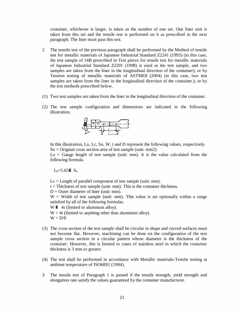
(1) Two test samples are taken from the liner in the longitudinal direction of the container. (2) The test sample configuration and dimensions are indicated in the following
illustration.
In this illustration, Lo, Lc, So, W, t and D represent the following values, respectively. So = Original cross section area of test sample (unit: mm2). Lo = Gauge length of test sample (unit: mm). It is the value calculated from the
following formula. L0=5.65√S0
Lc = Length of parallel component of test sample (unit: mm). t = Thickness of test sample (unit: mm). This is the container thickness. D = Outer diameter of liner (unit: mm). W = Width of test sample (unit: mm). This value is set optionally within a range
satisfied by all of the following formulas. W £ 4t (limited to aluminum alloy). W < 4t (limited to anything other than aluminum alloy). W < D/8 (3) The cross section of the test sample shall be circular in shape and curved surfaces must
not become flat. However, machining can be done on the configuration of the test sample cross section in a circular pattern whose diameter is the thickness of the container. However, this is limited to cases of stainless steel in which the container thickness is 3 mm or greater.
(4) The test shall be performed in accordance with Metallic materials-Tensile testing at
ambient temperature of ISO6892 (1984). 3 The tensile test of Paragraph 1 is passed if the tensile strength, yield strength and
elongation rate satisfy the values guaranteed by the container manufacturer.

22
(External Appearance Test in Batch Test) Article 22 1 The external appearance test shall be performed on each container liner (hereinafter
referred to as "liner" in this article) in accordance with the terms of the next paragraph and Paragraph 3. This test must be passed.
2 The external appearance test of the previous paragraph shall be performed in
accordance with the terms of each of the following items. (1) Visual inspection shall be conducted after rust and other impurities have been removed. (2) Lighting equipment shall be used for internal inspections. (3) The outer diameter and total length of the torso shall be measured. 3 The external appearance test of Paragraph 1 is passed if there are no obstacles to usage
such as corrosion, cracking, streaks, or wrinkles; if there are no gaps, flaws or impurities obstructing usage at the weld part in the liner of a VH4 container that has been welded; and if the outer diameter and total length of the torso satisfy the permissible design values.
(Non-destructive Test in Batch Test) Article 23 1 The non-destructive test shall be performed on the entire surface of each VH3
container liner (hereinafter referred to as "liner" in this article) in accordance with the terms of the next paragraph and Paragraph 3. This test must be passed.
2 The non-destructive test of the previous paragraph shall be carried out by means of the
ultrasonic test, whereby the maximum permissible defects stipulated in Article 19 can be detected, by the dye penetrant test, magnetic particle test, eddy current test or other suitable test.
3 The non-destructive test of Paragraph 1 is passed if the size of any defect is less than
the maximum permissible defect as stipulated in Article 19 and if there are no obstructions to usage due to correlations among flaws.
(Expansion Measurement Test in Batch Test) Article 24 1 The expansion measurement test shall be performed on each container in accordance
with the terms of the next paragraph and Paragraph 3. This test must be passed. 2 The expansion measurement test of the previous paragraph shall be performed in the
following manner. After the container has been filled with fluid so that no gaseous phase component remains inside it, pressure shall be added until it becomes at least 1.5 times the maximum filling pressure (hereinafter referred to as "test pressure" in this article). The container is held in this condition for 30 seconds and allowed to expand adequately. In this case, if the test pressure cannot be held constant because of

23
inadequate testing equipment, the container shall be held for at least 30 seconds after a pressure of 690 kPa or greater has been added to the test pressure, and the container shall be allowed to expand.
3 The expansion measurement test of Paragraph 1 is passed if there are no container
leaks or abnormal expansions, and if the permanent increase rate of the container satisfies the values stipulated by the container manufacturer.
(Leak Test in Batch Test) Article 25 1 The leak test shall be performed on each container (limited to VH4 containers) in
accordance with the terms of the next paragraph and Paragraph 3. This test must be passed.
2 For a container that has passed the expansion measurement test, the leak test of the
previous paragraph shall be carried out as follows. After the container has been dried and pressure has been added to it up to the maximum filling pressure or greater with an inert gas or dried air, including helium or other detection gas, the container is placed in an air-tight chamber and kept there for at least 1 minute. Gas concentration is then measured or gas is detected.
3 The leak test of Paragraph 1 is passed if no gas other than the transmitted gas is
detected. (Ambient Cycling Test in Batch Test) Article 26 1 The ambient cycling test shall be performed on the following container in accordance
with the terms of the next paragraph and Paragraph 3. The containers in question are all of the same type (exclusive of changes from h to k of Item 6, Article 2). When the number of containers provided for the tensile test, ambient cycling test and hydrostatic burst test is added to 200 containers that have been produced continuously, that number of containers, or the number of containers produced in one shift, whichever is larger, is taken as one set. One container is taken from this set and the ambient cycling test is performed on it as prescribed. This test must be passed. However, if five consecutive sets have passed the ambient cycling test, the periodic ambient cycling test of Paragraph 4 can be substituted.
2 The ambient cycling test of Paragraph 1 shall be performed in accordance with the
terms of each of the following items. (1) Pressure equal to or greater than 125% of the maximum filling pressure shall be added
at least 11,250 times at the rate of up to 10 additions per minute. (2) The terms of Item 2, Paragraph 2 of Article 11 shall apply to the ambient cycling test. 3 The ambient cycling test of Paragraph 1 is passed if there are no leaks or ruptures to
the container. 4 As for the periodic ambient cycling test in the proviso of Paragraph 1, the test shall be

24
performed in accordance with Paragraph 2 and Paragraph 3 on one container taken from each set as prescribed below. This test must be passed.
(1) Testing after five consecutive sets have passed the ambient cycling test can be done on
each set up to the 10th consecutive set. However, if 3 months have elapsed since the previous test, the test can be done on the first set after 3 months.
(2) If the ambient cycling test performed on each set up to the 10th consecutive set as
prescribed in the previous section is not passed, the test must be performed on the next consecutive set of 10 containers. If this consecutive set of 10 passes the test, it shall be recognized that the five consecutive sets of the proviso in Paragraph 1 have passed the test, and the periodic ambient cycling test can be performed.
(3) If the ambient cycling test performed on each set up to the 10th consecutive set as
prescribed in Item 1 is not passed, the test shall be performed on one container taken from a set other than the set represented by the container that failed. The set of containers that passed this test shall be regarded as having passed the test.
(Hydrostatic Burst test in Batch Test) Article 27 1 The hydrostatic burst test shall be performed on the following containers in
accordance with the terms of the next paragraph and Paragraph 3. The containers in question are all of the same type (exclusive of changes from h to k of Item 6, Article 2). When the number of containers provided for the tensile test, ambient cycling test and hydrostatic burst test is added to 200 containers that have been produced continuously, that number of containers, or the number of containers produced in one shift, whichever is larger, is taken as one set. One container is taken from this set and the hydrostatic burst test is performed on it. This test must be passed.
2 The terms of Paragraph 2, Article 10 shall apply to the hydrostatic burst test. 3 The terms of Paragraph 3, Article 10 shall apply to the hydrostatic burst test.
CHAPTER 4 TYPE TEST
(Type Test) Article 28 1 The "Type Test" stipulated in Paragraph 2, Article 7 of the Regulations includes the
following tests performed in accordance with the terms from the next paragraph to Paragraph 7: design inspection, plastic liner weld part tensile test, hydrostatic burst test, ambient cycling test, minimum thickness confirmation test, bonfire test, drop test, permeation test , environment test, hydrogen gas cycle test, accelerated stress hydrostatic burst test, flaw tolerance test, interlaminate shear test, tensile test, external appearance test, non-destructive test, expansion measurement test and leak test.
2 The design inspection, plastic liner weld part tensile test, hydrostatic burst test,
ambient cycling test, minimum thickness confirmation test, bonfire test, drop test, permeation test , environment test, hydrogen gas cycle test, accelerated stress

25
hydrostatic burst test, flaw tolerance test and interlaminate shear test, all cited in the previous paragraph, are performed through examples of the design qualification test in Article 8, Article 9, Article 10, Article 11, Article 12, Article 13, Article 14, Article 15, Article 16, Article 17, Article 18, Article 19 and Article 20, respectively.
3 The tensile test of Paragraph 1 shall be performed through examples of the tensile test
in the batch test of Article 21. However, in Paragraph 1 of the same article, it states: "The liner is of the same type (exclusive of changes from h to k of Item 6, Article 2). When the number of liners provided for the tensile test, ambient cycling test and hydrostatic burst test is added to 200 liner units produced continuously, the number of liners obtained, or the number of units produced in one shift of the container liner, whichever is larger, is taken as the number of one set. One liner unit is taken from this set." The phrase, "taken from the same type" is to be read in place of this statement.
4 The external appearance test of Paragraph 1 shall be performed through examples of
the external appearance test in the batch test of Article 22. However, in Paragraph 1 of the same article, it states: "for each liner," but the phrase, "five liners taken from the same type" is to be read in place of this.
5 The non-destructive test of Paragraph 1 shall be performed through examples of non-
destructive test in the batch test of Article 23. However, in Paragraph 1 of the same article, it states: "for each liner," but the phrase, "5 liners taken from the same type" is to be read in place of this.
6 The expansion measurement test of Paragraph 1 shall be performed through examples
of the expansion measurement test in the batch test of Article 24. However, in Paragraph 1 of the same article, it states: "for each container," but the phrase, "five containers taken from the same type" is to be read in place of this.
7 The leak test of Paragraph 1 shall be performed through examples of the leak test in
the batch test of Article 25. However, in Paragraph 1 of the same article, it states: "for each container," but the phrase, "five containers taken from the same type" is to be read in place of this.
(Exceptions to Application of Type Test) Article 29 Despite the terms of the previous article, the type test can be performed as prescribed
below. (1) For changes to types that have passed the type test in the execution of all tests and
inspections (hereinafter "tests, etc." in this article) associated with the type test (hereinafter "basic type" in this article), in accordance with the type of container given in the left column of Attached Table 1 or Attached Table 2 (hereinafter "Attached Table 1, etc."), in the execution of the type test of type applicable to any of the design change categories in type changes in the central column of the same attached table, application of tests, etc., other than applicable tests, etc., in the right column of the same attached table can be omitted.
(2) Of the types which have passed the design qualification test without application of
26
tests, etc., other than applicable tests, etc., given in the right column of Attached Table 1, etc., based on the terms of the previous item, if the reason that the type differs from the basic type is a change in the items given from h to k of Item 6, Article 2, and if the items given from a to g of the same item have not undergone a change in design, the type is regarded as a basic type.
(3) In Item 1, if changes in basic type are associated with any of the items given in h to k
of Item 6, Article 2, and in addition, if the change is applicable to the items given in a to g of the same item, the tests associated with the changes from a to g of the same item need not be applied.

27
Attached Table 1 (Pertaining to Article 7 and Article 29)
Design Qualification Test or Type Test
Container type
Design change category in type change Design
inspection Hydrostatic
burst test Ambient
cycling test
Minimum thickness
confirmation test
Bonfire test Drop test Environment test
Accelerated stress
hydrostatic burst test
Flaw tolerance test
Interlaminate shear test
Fiber material and fiber manufacturer O O O Note 1
O Note 1
O Note 1 O O O
Note 1 O
Note 1 O
Resin material O O O Note 6 O
Note 6 O
Note 6 O O
Liner material O O O O Change of 20% or less Note 4 O O
Note 3 O
Note 3 O O Outer diameter of torso Change in excess of 20%
Note 4 O O O O O O O
Change of 20% or less in maximum filling pressure Note 4
O O Note 3
O Note 3 O O
Change of 50% or less O O Note 3 O
Note 2 Total length Change in excess of 50% O O
Note 3 O O
Valves and/or safety valves O O Note 5
End configuration and dimensions Note 3 O O O
VH3 container
Change to other container from container for cargo room Note 7
O O
Remarks O denotes applicable test. Note 1 Applicable only when there is a change to the type of fiber material. Note 2 Not necessary if the containers that have already passed the bonfire test, safety valves and arrangements thereof are uniform, and if the internal cubic capacity of the container does not become large. Note 3 The number of containers required for testing shall be one. Note 4 Cases of change such that the stresses of compositional material in the container wall become equivalent or below that value when the outer diameter of torso or the maximum filling pressure is changed. Note 5 Applicable in the case of any one of the following changes · Case in which the increase in weight of the valve which comes as a single unit with safety valve, or the increase in weight of the safety valve when the safety valve is installed as a separate unit, is 30% or
more. · Case in which the number of safety valves has diminished. · Case in which the area of the gas discharge path has diminished during safety valve operation. Note 6 Not necessary in cases of material of chemical equivalency. Note 7 Not required in case of container for cargo room.

28
Attached Table 2 (Pertaining to Article 7 and Article 29)
Design Qualification Test or Type Test
Container type
Design change category in type change Design
inspection
Plastic liner weld part
tensile test
Hydrostatic burst test
Ambient cycling test
Minimum thickness
confirmation test
Bonfire test Drop test Gas
permeation test
Environment test
Hydrogen gas cycle test
Accelerated stress burst
test
Interlaminate shear test
Fiber material and fiber manufacturer O O O Note 1
O Note 1
O Note 1 O O O
Note 1 O
Resin material O O O Note 6 O
Note 6 O Note 6 O O
Liner material O O O O O Note 7 O O
Note 7 O
Note 7
Change of 20% or less Note 2, Note 3 O O O O Outer
diameter of torso Change in excess of 20%
Note 3 O O O O O O
Change of 20% or less in maximum filling pressure Note 2, Note 3
O O O O
Change of 50% or less O O Note 2
O Note 4
Total length Change in excess of 50% O O
Note 2 O O
Valves and/or safety valves Note 5 O O Boss Note 2 O O O
VH4 container
Change to other container from container for cargo room
O O
Remarks O denotes applicable test. Note 1 Applicable only when there is a change to the type of fiber material. Note 2 The number of containers required for testing shall be one. Note 3 Cases of change such that the stresses of compositional material in the container wall become equivalent or below that value when the outer diameter of torso or the maximum filling pressure is changed. Note 4 Not necessary if the containers that have already passed the bonfire test, safety valves and arrangements thereof are uniform, and if the internal cubic capacity of the container does not become large. Note 5 Applicable in the case of any one of the following changes · Case in which the increase in weight of the valve which comes as a single unit with safety valve, or the increase in weight of the safety valve when the safety valve is installed as a separate unit, is 30% or
more. · Case in which the number of safety valves has diminished. · Case in which the area of the gas discharge path has diminished during safety valve operation. Note 6 Not necessary in cases of material of chemical equivalency. Note 7 Required only in the case of change to polymer. Note 8 Not required in case of container for cargo room.

29
Attached Table 3 (Pertaining to Article 8) Design Inspection
Item Content Test sample
1. One test sample shall be taken from the boss of the container shown in the illustration or in the vicinity of the boss from the circumferential direction.
2. The test sample configuration and dimensions shall be as stipulated in the
examples of the following: 14A test sample prescribed in Test pieces for tensile test for metallic materials of Japan Industrial Standard Z2201 (1998); standard tensile test sample of circular cross section having a diameter of 12.5 mm, where the gauge distance of Fig 8 under Tension testing of metallic materials (meter method) of ASTM E8M (2004) is five times the diameter; and small-size test sample proportionate to the standard test sample. However, if the retrievable test sample diameter is less than 2.5 mm, the test sample diameter shall be the largest retrievable diameter and the gauge distance shall be five times the diameter or greater.
Test method
1. The test is performed as prescribed in Method of tensile test for metallic materials of Japan Industrial Standard Z2241 (1993), or Tension testing of metallic materials (meter method) of ASTM E8M (2004).
2. It shall be confirmed that the measured yield strength is a value at which there is no yield with a pressure 1.5 times the maximum filling pressure.
Position at which test sample is cut out. (Example)

30
October 19, 2004 Attached Table 4 (Pertaining to Article 16) Outline of Environment Test
Immersion test and environmental test with two containers Immersion test and environmental test with one container
Test limited to containers for cargo room (1 container)
Pretreatment (1)
Pendulum impact · Three locations at bottom portion of
torso · One location each at bottom of both end
mirrors
Pretreatment (2)-2
Pebble impact · Five locations at upper portion of
torso · Diameter at 10 cm
Pretreatment (2)-2 Pebble impact
· Five locations at upper portion of torso · Diameter at 10 cm
Environment Exposure
· Five locations at pretreatment component of torso upper portion
· Environment exposure fluid dropped at 5 ml or more to each location
· P0 x 125%, 40 minutes
Environment Exposure · Five locations at pretreatment
component of torso upper portion · Environment exposure fluid dropped at
5 ml or more to each location · P0 x 125%, 40 minutes
Immersion
· Lower component 1/3 immersion fluid
· Fluid temperature at 21°C
Immersion · Lower component 1/3 immersion fluid · Fluid temperature at 21°C
Cycle (1) · 2 MPa or below « P0 x 125% x 60
seconds, 5,625 sessions · Room temperature
Cycle (1) · 2 MPa or below « P0 x 125% x 60
seconds, 5,625 sessions · Room temperature
Environment Exposure
· Five locations at pretreatment component of torso upper portion
· Environment exposure fluid dropped at 5 ml or more to each location
· P0 x 125%, 40 minutes
Environment Exposure · Five locations at pretreatment
component of torso upper portion · Environment exposure fluid dropped at
5 ml or more to each location · P0 x 125%, 40 minutes
Cycle (2)
· 2 MPa or below « P0 x 80% x 60 seconds, 2,820 sessions
· –40°C ±5°C ambient temperature
Cycle (2) · 2 MPa or below « P0 x 80% x 60
seconds, 2,820 sessions · –40°C ±5°C ambient temperature
Cycle (2) · 2 MPa or below « P0 x 80% x 60
seconds, 2,820 sessions · –40°C ±5°C ambient temperature
Cycle (2) · 2 MPa or below « P0 x 80% x 60
seconds, 2,820 sessions · –40°C ±5°C ambient temperature
Environment Exposure
· Five locations at pretreatment component of torso upper portion
· Environment exposure fluid dropped at 5 ml or more to each location
· P0 x 125%, 40 minutes
Environment Exposure · Five locations at pretreatment
component of torso upper portion · Environment exposure fluid dropped at
5 ml or more to each location · P0 x 125%, 40 minutes
Cycle (3)
· 2 MPa or below « P0 x 125% x 60 seconds, 2,820 sessions
· 85°C ±5°C ambient temperature
Cycle (3) · 2 MPa or below « P0 x 125% x 60
seconds, 2,820 sessions · 85°C ±5°C ambient temperature
Cycle (3) · 2 MPa or below « P0 x 125% x 60
seconds, 2,820 sessions · 85°C ±5°C ambient temperature
Cycle (3) · 2 MPa or below « P0 x 125% x 60
seconds, 2,820 sessions · 85°C ±5°C ambient temperature
Hydrostatic burst test Hydrostatic burst test Hydrostatic burst test Hydrostatic burst test
P0: Maximum filling pressure P0: Maximum filling pressure P0: Maximum filling pressure
Cycle (1) · 2 MPa or below « P0 x 125% x 60 seconds, 5,625 sessions · Room temperature
Cycle (1) · 2 MPa or below « P0 x 125% x 60
seconds, 5,625 sessions · Room temperature
Pretreatment (1) Pendulum impact
· Three locations at bottom portion of torso · One location each at bottom of
both end mirrors
Pretreatment (1) Pendulum impact
· Three locations at bottom portion of torso · One location each at bottom of both
end mirrors
Pretreatment (2)-1 Pebble impact
· Three locations at pendulum impact component
Pretreatment (2)-1 Pebble impact
· Three locations at pendulum impact component
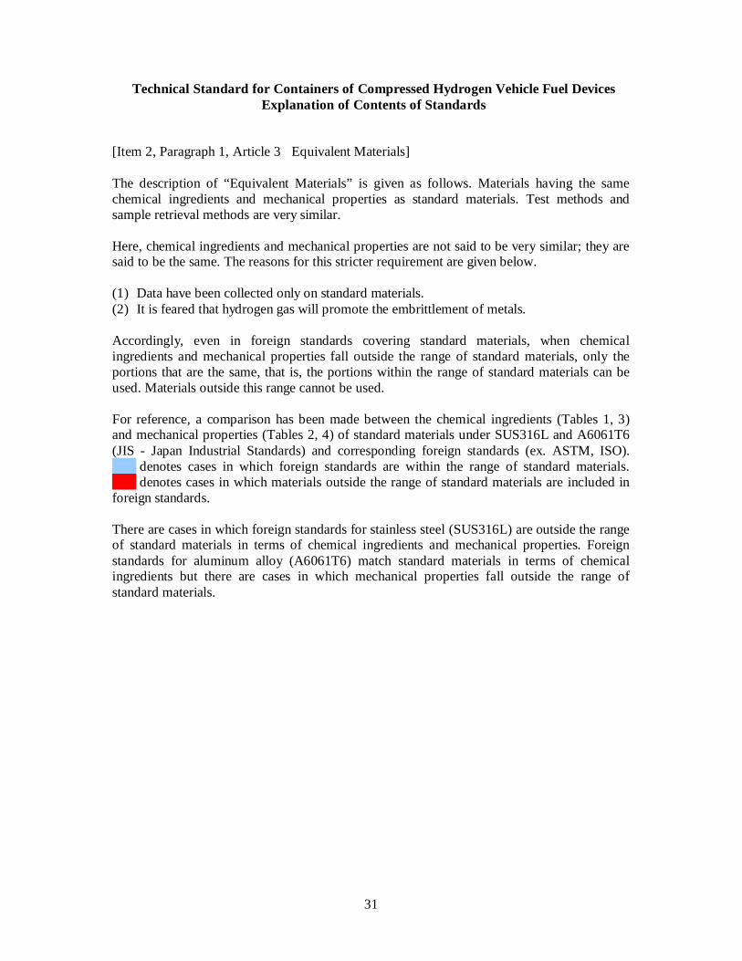
31
Technical Standard for Containers of Compressed Hydrogen Vehicle Fuel Devices Explanation of Contents of Standards
[Item 2, Paragraph 1, Article 3 Equivalent Materials]
The description of “Equivalent Materials” is given as follows. Materials having the same chemical ingredients and mechanical properties as standard materials. Test methods and sample retrieval methods are very similar. Here, chemical ingredients and mechanical properties are not said to be very similar; they are said to be the same. The reasons for this stricter requirement are given below. (1) Data have been collected only on standard materials. (2) It is feared that hydrogen gas will promote the embrittlement of metals. Accordingly, even in foreign standards covering standard materials, when chemical ingredients and mechanical properties fall outside the range of standard materials, only the portions that are the same, that is, the portions within the range of standard materials can be used. Materials outside this range cannot be used. For reference, a comparison has been made between the chemical ingredients (Tables 1, 3) and mechanical properties (Tables 2, 4) of standard materials under SUS316L and A6061T6 (JIS - Japan Industrial Standards) and corresponding foreign standards (ex. ASTM, ISO). denotes cases in which foreign standards are within the range of standard materials. denotes cases in which materials outside the range of standard materials are included in foreign standards. There are cases in which foreign standards for stainless steel (SUS316L) are outside the range of standard materials in terms of chemical ingredients and mechanical properties. Foreign standards for aluminum alloy (A6061T6) match standard materials in terms of chemical ingredients but there are cases in which mechanical properties fall outside the range of standard materials.

32
Table 1 Comparison of standards covering SUS316L (chemical ingredients)
: JIS ³ ASTM, ISO : JIS < ASTM, ISO
Standards C Mn P S Si Ni Cr Mo N G3214 0.030 2.00 0.040 0.030 1.00 12.00-15.00 16.00-18.00 2.00-3.00 G3459 0.030 2.00 0.040 0.030 1.00 12.00-16.00 16.00-18.00 2.003.00 G4303 0.030 2.00 0.040 0.030 1.00 12.00-15.00 16.00-18.00 2.00-3.00 G4304 0.030 2.00 0.040 0.030 1.00 12.00-15.00 16.00-18.00 2.00-3.00
JIS
G4305 0.030 2.00 0.040 0.030 1.00 12.00-15.00 16.00-18.00 2.00-3.00 A182/182M-04 0.030 2.00 0.045 0.030 1.00 10.0-15.0 16.0-18.0 2.00-3.00 A240/240M-04a 0.030 2.00 0.045 0.030 0.75 10.0-14.0 16.0-18.0 2.00-3.00 0.10 A276-04 0.030 2.00 0.045 0.030 1.00 10.0-14.0 16.0-18.0 2.00-3.00 A312/312M-04a 0.035 2.00 0.045 0.030 1.00 10.0-14.0 16.0-18.0 2.00-3.00
ASTM
A666-03 0.030 2.00 0.045 0.030 0.75 10.0-14.0 16.0-18.0 2.00-3.00 0.030 2.00 0.045 0.030 1.00 10.0-13.0 16.5-18.5 2.00-3.00 0.11 TS15510 0.030 2.00 0.045 0.030 1.00 10.5-13.0 16.5-18.5 2.00-3.00 0.11 0.030 2.00 0.045 0.030 1.00 11.0-14.0 16.5-18.5 2.00-2.50 ISO
9327-5 0.030 2.00 0.045 0.030 1.00 11.5-14.5 16.5-18.5 2.50-3.00 * The unit is mass%. Values given outside the range are upper limit values.
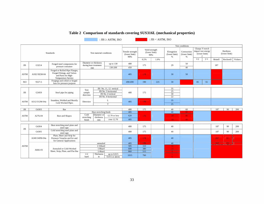
33
Table 2 Comparison of standards covering SUS316L (mechanical properties)
: JIS ³ ASTM, ISO : JIS < ASTM, ISO
Test conditions
Yield strength (lower limit)
MPa
Charpy V-notch impact test energy
(lower limit) J
Hardness (lower limit) Standards Test material conditions Tensile strength
(lower limit) MPa
0.2% 1.0%
Elongation (lower limit)
%
Contraction (lower limit)
% x-y y-x Brinell Rockwell Vickers
up to 130 480 50 JIS G3214 Forged steel components for
pressure container
Diameter or thickness during heat treatment
mm 130-200 450 175 29
40 187
ASTM A182/182M-04
Forged or Rolled Pipe Flanges, Forged Fittings, and Valves
and Parts for High-Tempareture Service
485 170 30 50
ISO 9327-5 Forgings and rolled or forged bars for pressure purpose 490-690 190 225 30 85 55
JIS No. 11, 12 vertical 35
JIS No. 5 horizontal 25 JIS No. 4 vertical 30
JIS G3459 Steel pipe for piping Test
sample direction
JIS No. 4 horizontal
480 175
22
L 35 ASTM A312/312M-04a Seamless, Welded and Heavily Cold Worked Pipes Direction
T 485 170
25
JIS G4303 Bar 480 175 40 60 187 90 200
Heat stretching finish 485 40 50 12.70 or less 620 30 40 ASTM A276-04 Bars and Shapes Cold
stretching finish
Diameter or thickness
mm over 12.70 485
170
30 40
G4304 Heat stretching steel plate and steel tape 480 175 40 187 90 200
JIS G4305 Cold stretching steel plate and
steel tape 480 175 40 187 90 200
A240/240M-04a Plate, Sheet and Strip for
Pressure Vesseles and for and for General Applications
485 170 40 217 95
annealed 485 170 40 217 95 1/16hard 585 310 35 1/8hard 690 380 25 1/4hard 860 515 8
up to 0.015 5
ASTM
A666-03 Annealed or Cold-Worked Sheet, Strip, Plate, and Flat Bar
1/2 hard
Thickness in 0.015 or above
1035 760
6
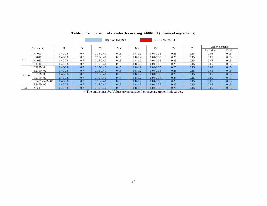
34
Table 3 Comparison of standards covering A6061T1 (chemical ingredients)
: JIS ³ ASTM, ISO : JIS < ASTM, ISO
Other elements Standards Si Fe Cu Mn Mg Cr Zn Ti Individual Total H4000 0.40-0.8 0.7 0.15-0.40 0.15 0.8-1.2 0.04-0.35 0.25 0.15 0.05 0.15 H4040 0.40-0.8 0.7 0.15-0.40 0.15 0.8-1.2 0.04-0.35 0.25 0.15 0.05 0.15 H4080 0.40-0.8 0.7 0.15-0.40 0.15 0.8-1.2 0.04-0.35 0.25 0.15 0.05 0.15 JIS
H4140 0.40-0.8 0.7 0.15-0.40 0.15 0.8-1.2 0.04-0.35 0.25 0.15 0.05 0.15 B209M-04 0.40-0.8 0.7 0.15-0.40 0.15 0.8-1.2 0.04-0.35 0.25 0.15 0.05 0.15 B210M-02 0.40-0.8 0.7 0.15-0.40 0.15 0.8-1.2 0.04-0.35 0.25 0.15 0.05 0.15 B211M-03 0.40-0.8 0.7 0.15-0.40 0.15 0.8-1.2 0.04-0.35 0.25 0.15 0.05 0.15 B211M-02 0.40-0.8 0.7 0.15-0.40 0.15 0.8-1.2 0.04-0.35 0.25 0.15 0.05 0.15 B241/B241M-02 0.40-0.8 0.7 0.15-0.40 0.15 0.8-1.2 0.04-0.35 0.25 0.15 0.05 0.15
ASTM
B247M-02a 0.40-0.8 0.7 0.15-0.40 0.15 0.8-1.2 0.04-0.35 0.25 0.15 0.05 0.15 ISO 209-1 0.40-0.8 0.7 0.15-0.40 0.15 0.8-1.2 0.04-0.35 0.25 0.15 0.05 0.15
* The unit is mass%. Values given outside the range are upper limit values.

35
Table 4 Comparison of standards covering A6061T6 (mechanical properties)
: JIS ³ ASTM, ISO : JIS < ASTM, ISO
Test conditions Elongation
(lower limit) %
Hardness (lower limit) Standards Test material conditions Tensile strength
(lower limit) MPa
Yield strength (lower limit)
Mpa 50mm 5 times the
diameter Brinell
0.4-0.5 8 JIS H4000 Plate and strips Thickness
mm 0.5-6.5 295
245 10
0.15-0.20 4 0.20-0.25 6 0.25-0.50 8
ASTM B209M-04 Sheet and Plate Plate thickness mm
0.50-6.30
290 240
10
-6 JIS H4040 Extrusion rod Diameter or minimum opposite side distance
mm 6- 265
245 10
-6.30 8 ASTM B221M-02 Extruded Bars, Rods, Wire, Profiles, and Tubes
Wall thickness mm 6.30-
260 240 10 9
6.30 or less 8 7 Rod/Bar Diameter mm From 6.3 up to 100
260 240 10 9
6.30 or less 8 7 ISO 6362-2
Profile Thickness mm From 6.3 up to 100
260 240 10 9
-3 8 JIS H4040 Drawn rod and line Diameter or minimum opposite side distance
mm 3-100 295 245
10
-3.20 ASTM B211M-03 Bar, Rod and Wire Diameter or thickness mm 3.20-200.00
290 240 10 9
ISO 6363-2 Rod/Bar Diameter mm 80 or less 290 240 10 9
8 JIS H4080 Seamless extrusion pipe Wall thickness
mm 6 or less over 6 265 245
10
8 ASTM B241/B241M-02 Seamless Pipe and Seamless Extruded Tube
Wall thickness mm
-6.30 6.30- 260 240
10
6.3 or less 8 7 ISO 6362-2 Tube Wall thickness mm From 6.3 up to 25
260 240 10 9
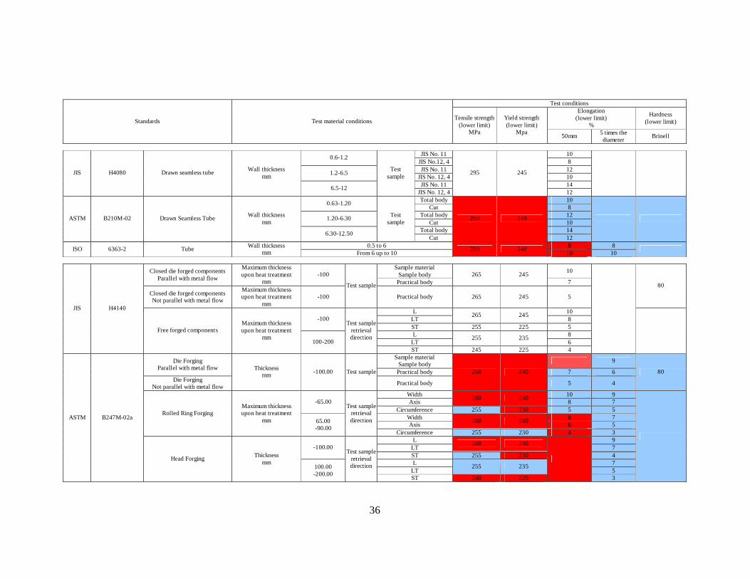
36
Test conditions
Elongation (lower limit)
%
Hardness (lower limit) Standards Test material conditions Tensile strength
(lower limit) MPa
Yield strength (lower limit)
Mpa 50mm 5 times the diameter Brinell
JIS No. 11 10 0.6-1.2
JIS No.12, 4 8 JIS No. 11 12 1.2-6.5
JIS No. 12, 4 10 JIS No. 11 14
JIS H4080 Drawn seamless tube Wall thickness mm
6.5-12
Test sample
JIS No. 12, 4
295 245
12
Total body 10 0.63-1.20 Cut 8
Total body 12 1.20-6.30 Cut 10
Total body 14
ASTM B210M-02 Drawn Seamless Tube Wall thickness mm
6.30-12.50
Test sample
Cut
290 240
12
0.5 to 6 8 8 ISO 6363-2 Tube Wall thickness mm From 6 up to 10
290 240 10 10
Sample material
Sample body 10 Closed die forged components Parallel with metal flow
Maximum thickness upon heat treatment
mm -100
Practical body 265 245
7
Closed die forged components Not parallel with metal flow
Maximum thickness upon heat treatment
mm -100
Test sample
Practical body 265 245 5
80
L 10 LT
265 245 8 -100
ST 255 225 5 L 8
LT 255 235
6
JIS H4140
Free forged components Maximum thickness upon heat treatment
mm 100-200
Test sample retrieval direction
ST 245 225 4
Sample material Sample body 9 Die Forging
Parallel with metal flow Practical body 7 6
Die Forging Not parallel with metal flow
Thickness mm -100.00 Test sample
Practical body
260 240
5 4
80
Width 10 9 Axis
260 240 8 7 -65.00
Circumference 255 230 5 5 Width 8 7 Axis 260 240 6 5
Rolled Ring Forging Maximum thickness upon heat treatment
mm 65.00 -90.00
Test sample retrieval direction
Circumference 255 230 4 3 L 9
LT 260 240
7 -100.00 ST 255 230 4 L 7
LT 255 235
5
ASTM B247M-02a
Head Forging Thickness mm
100.00 -200.00
Test sample retrieval direction
ST 240 220
3
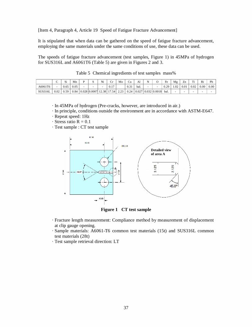
37
[Item 4, Paragraph 4, Article 19 Speed of Fatigue Fracture Advancement] It is stipulated that when data can be gathered on the speed of fatigue fracture advancement, employing the same materials under the same conditions of use, these data can be used. The speeds of fatigue fracture advancement (test samples, Figure 1) in 45MPa of hydrogen for SUS316L and A6061T6 (Table 5) are given in Figures 2 and 3.
Table 5 Chemical ingredients of test samples mass%
C Si Mn P S Ni Cr Mo Cu Al N O Fe Mg Zn Ti Bi Pb A6061T6 - 0.65 0.05 - - - 0.17 0.31 bal. - - 0.29 1.02 0.01 0.02 0.00 0.00 SUS316L 0.02 0.59 0.84 0.028 0.0007 12.38 17.54 2.23 0.24 0.027 0.032 0.0018 bal. - - - - - · In 45MPa of hydrogen (Pre-cracks, however, are introduced in air.) · In principle, conditions outside the environment are in accordance with ASTM-E647. · Repeat speed: 1Hz · Stress ratio R = 0.1 · Test sample : CT test sample
Figure 1 CT test sample
· Fracture length measurement: Compliance method by measurement of displacement
at clip gauge opening. · Sample materials: A6061-T6 common test materials (15t) and SUS316L common
test materials (28t) · Test sample retrieval direction: LT
Detailed view of area A
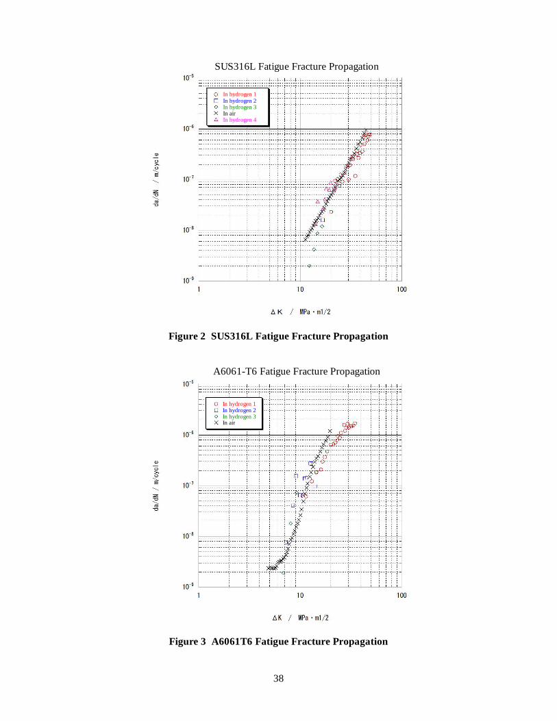
38
SUS316L Fatigue Fracture Propagation
Figure 2 SUS316L Fatigue Fracture Propagation
A6061-T6 Fatigue Fracture Propagation
Figure 3 A6061T6 Fatigue Fracture Propagation
In hydrogen 1 In hydrogen 2 In hydrogen 3 In air In hydrogen 4
In hydrogen 1 In hydrogen 2 In hydrogen 3 In air