technical standard of in-building fibre …mtsfb.org.my/sites/default/files/fttp cabling rev... ·...
TRANSCRIPT
Let’s Collaborate@MTSFB!
TECHNICAL STANDARD OFIN-BUILDING FIBRE CABLING FOR
FIBRE-TO-THE-PREMISEREV 1.0
Mohd Yusairi Abu HassanSept-2017
Let’s Collaborate@MTSFB!Let’s Collaborate@MTSFB!
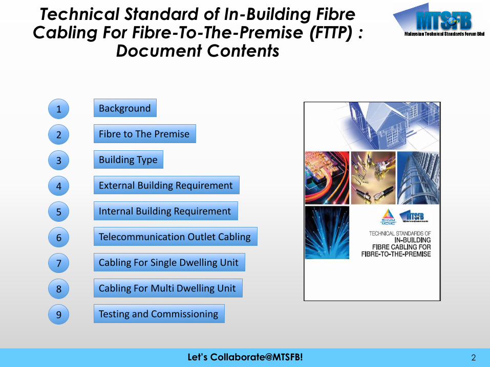
Technical Standard of In-Building Fibre Cabling For Fibre-To-The-Premise (FTTP) :
Document Contents
2
Background1
Fibre to The Premise2
Building Type3
External Building Requirement4
Internal Building Requirement5
Telecommunication Outlet Cabling6
Cabling For Single Dwelling Unit7
Cabling For Multi Dwelling Unit8
Testing and Commissioning9
Let’s Collaborate@MTSFB!Let’s Collaborate@MTSFB!
Document Background
Objectives:
• It outlines the infrastructure requirements to consulting engineers,Property Developers, owners and other responsible parties for theprovisions to be made available in the buildings.
• It also provides the minimum technical specifications necessary for theFixed Network Telephony and Multi broadband distribution system tofunction as require in buildings.
Scope :
• System infrastructure requirement in building (condo/ apartment, low costflats, single dwelling and office buildings).
• Minimum planning and installation planning guidelines and standards.
• Minimum technical and performance specifications for the services
3

Let’s Collaborate@MTSFB!Let’s Collaborate@MTSFB!
Fibre to the Building (FTTP)
Benefit of Fibre Optic Cable (FOC)
• Fibre-optic technology can carry massive amounts of information over long
distances with almost unlimited bandwidth
• An alternate solution to metal type infrastructure as it is capable to offer
faster and more reliable services which require a higher bandwidth.
• Less susceptible to outages caused by weather or electromagnetic
interference
• Future proof technology which has the ability to accommodate any new
technologies and applications that requires higher bandwidth with much
lower maintenance and operational cost.
4
Bundle of Fibre Optic Cable (FOC). i.e 24 cores
2 cores 2 cores 2 cores 2 cores
2 cores FOC Branches Closure
NFP Central Office
End User Premise
Point To Point Fibre Network Design Point To Multi Point (P2MP) Fibre Network Design
Let’s Collaborate@MTSFB!Let’s Collaborate@MTSFB!
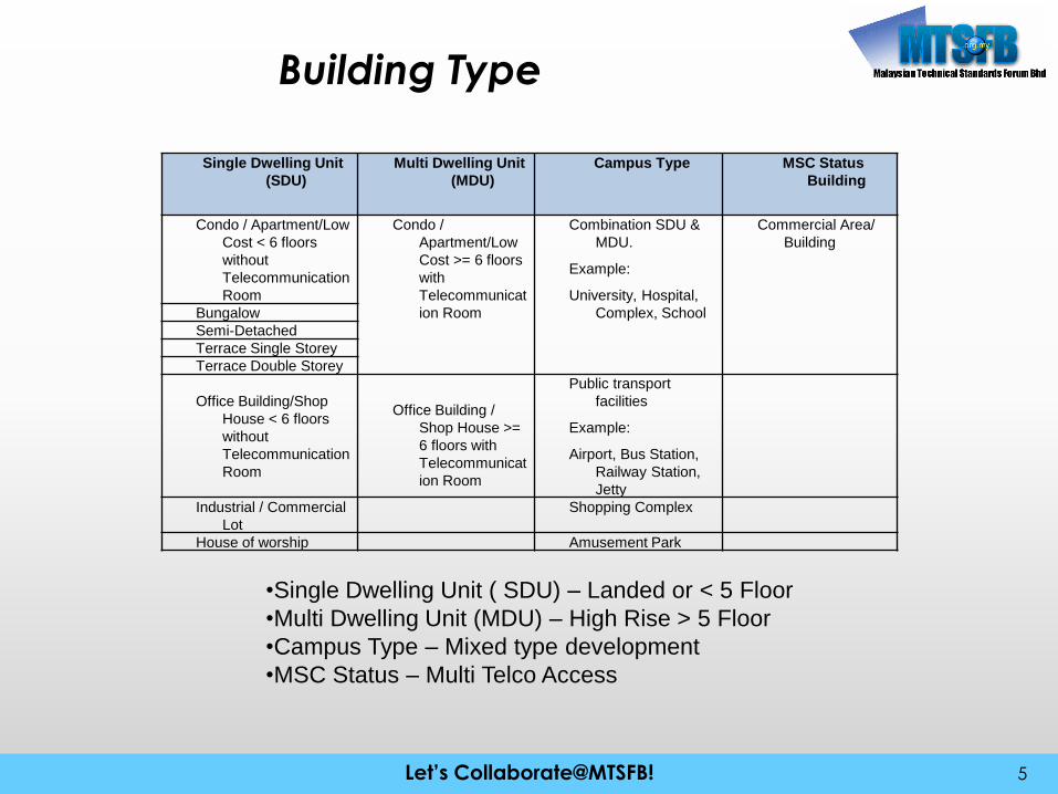
Building Type
5
Single Dwelling Unit
(SDU)
Multi Dwelling Unit
(MDU)
Campus Type MSC Status
Building
Condo / Apartment/Low
Cost < 6 floors
without
Telecommunication
Room
Condo /
Apartment/Low
Cost >= 6 floors
with
Telecommunicat
ion Room
Combination SDU &
MDU.
Example:
University, Hospital,
Complex, School
Commercial Area/
Building
Bungalow
Semi-Detached
Terrace Single Storey
Terrace Double Storey
Office Building/Shop
House < 6 floors
without
Telecommunication
Room
Office Building /
Shop House >=
6 floors with
Telecommunicat
ion Room
Public transport
facilities
Example:
Airport, Bus Station,
Railway Station,
Jetty
Industrial / Commercial
Lot
Shopping Complex
House of worship Amusement Park
•Single Dwelling Unit ( SDU) – Landed or < 5 Floor
•Multi Dwelling Unit (MDU) – High Rise > 5 Floor
•Campus Type – Mixed type development
•MSC Status – Multi Telco Access

Let’s Collaborate@MTSFB!Let’s Collaborate@MTSFB!
External Building Requirement –Demarcation Point
6
During Development:Is referring to development phase of the building or development area which
generally between Property Developer and NFP
Over Build:Is after the completion of the building or development area which generally
between NFP and Building Management
Development area
Development Premise / Building
NFPManhole
NFP Cable
Tab BlockInfrastructure Demarcation Point
CPENFP FTB
Developer/Premise Owner
NFP
PIT
Fence
MH
Infrastructure Demarcation Point
Properties Developer/Premise Owner Responsibility NFP Responsibility
MH
U/G Ducting
Development area
NFP ManholePremise Owner Manhole
Private Property Line (PPL)
Private Property Line (PPL)
Link –Up Infrastructure

Let’s Collaborate@MTSFB!Let’s Collaborate@MTSFB!
External Building Requirement –Demarcation Point
7
MDU Infrastructure
Demarcation Point
SDU Demarcation
Point
Let’s Collaborate@MTSFB!Let’s Collaborate@MTSFB!
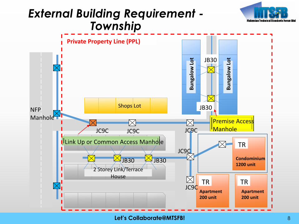
External Building Requirement -Township
8
Private Property Line (PPL)
Bu
nga
low
Lo
t
Bu
nga
low
Lo
t
TR
Condominium1200 unit
TRApartment200 unit
TRApartment200 unit
2 Storey Link/Terrace House
Shops Lot
JC9C JC9C JC9C
Link Up or Common Access Manhole
JC9C
JC9C
JB30
JB30
JB30JB30
Premise AccessManhole
NFPManhole

Let’s Collaborate@MTSFB!Let’s Collaborate@MTSFB!
External Building Requirement –Underground ducting
9
JB30
No. of Duct Way = 2Premise Access Duct Way = 4
Duct Way
JB30
PremiseLinked Duct
Underground Duct Arrangement
Duct depth specification
Sample 8 Ways of Duct Usage Sequence
Cable and Ducting Management
Let’s Collaborate@MTSFB!Let’s Collaborate@MTSFB!
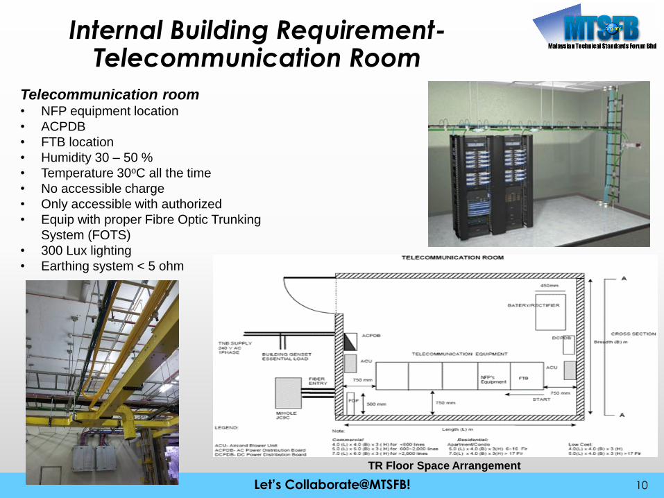
Internal Building Requirement-Telecommunication Room
10
Telecommunication room• NFP equipment location
• ACPDB
• FTB location
• Humidity 30 – 50 %
• Temperature 30oC all the time
• No accessible charge
• Only accessible with authorized
• Equip with proper Fibre Optic Trunking
System (FOTS)
• 300 Lux lighting
• Earthing system < 5 ohm
TR Floor Space Arrangement

Let’s Collaborate@MTSFB!Let’s Collaborate@MTSFB!
Internal Building Requirement-Trunking and Riser
11
Riser and Trunking• Vertical and Horizontal trunking connection TR/FTB to individual FWS
• Riser room at each floor
• Riser/Floor FTB - optional
Let’s Collaborate@MTSFB!Let’s Collaborate@MTSFB!
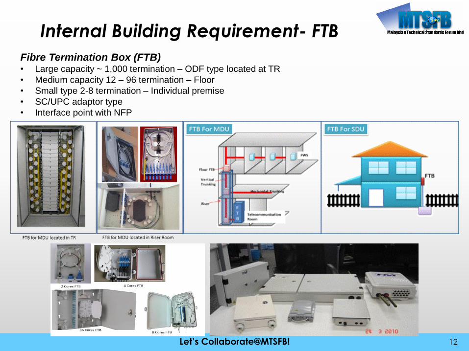
Internal Building Requirement- FTB
12
Fibre Termination Box (FTB)• Large capacity ~ 1,000 termination – ODF type located at TR
• Medium capacity 12 – 96 termination – Floor
• Small type 2-8 termination – Individual premise
• SC/UPC adaptor type
• Interface point with NFP
Let’s Collaborate@MTSFB!Let’s Collaborate@MTSFB!
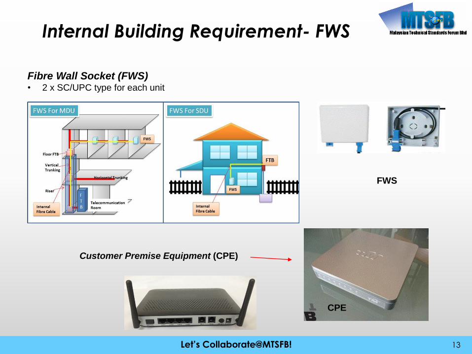
Internal Building Requirement- FWS
13
Fibre Wall Socket (FWS)• 2 x SC/UPC type for each unit
FWS
CPE
Customer Premise Equipment (CPE)

Let’s Collaborate@MTSFB!Let’s Collaborate@MTSFB!
Telecommunication Outlet Requirement
14
RG
CPE
RJ45Ethernet
Wi-Fi
RJ11
Fibre
STB
RJ45
RJ45
RJ45
RJ11
IPTV
PC
IP Phone
AnalogPhone
WirelessDevice
CPE: Customer Premise Equipment, RG: Residential Gateway, IPTV: Internet Protocol TV, STB: Setop Box

Let’s Collaborate@MTSFB!Let’s Collaborate@MTSFB!
Telecommunication Outlet Requirement
15
Cabling Design- CPE Location based on customer preferences
- Flexible terminal cabling
Let’s Collaborate@MTSFB!Let’s Collaborate@MTSFB!
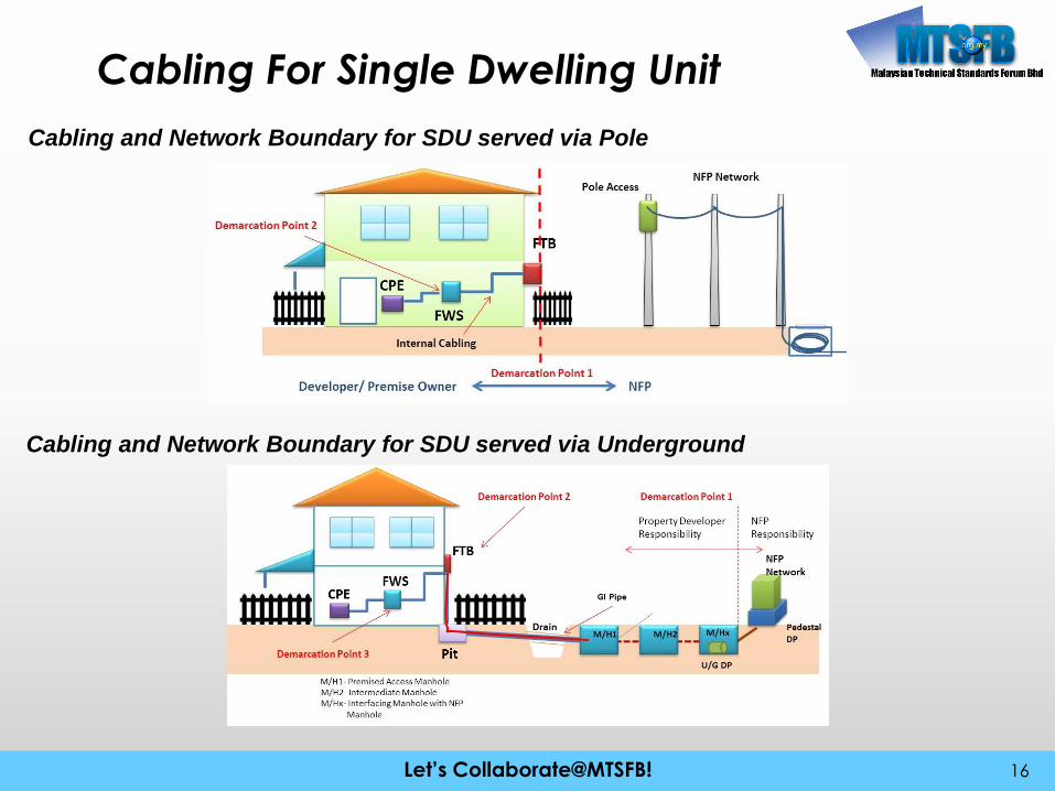
Cabling For Single Dwelling Unit
16
Cabling and Network Boundary for SDU served via Pole
Cabling and Network Boundary for SDU served via Underground

Let’s Collaborate@MTSFB!Let’s Collaborate@MTSFB!
Cabling For Single Dwelling Unit
17
Cabling and Network Boundary for SDU served via Underground

Let’s Collaborate@MTSFB!Let’s Collaborate@MTSFB!
Cabling For Single Dwelling Unit
18
Cabling and Network Boundary for Bungalow Type SDU
Let’s Collaborate@MTSFB!Let’s Collaborate@MTSFB!
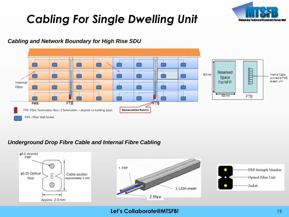
Cabling For Single Dwelling Unit
19
Cabling and Network Boundary for High Rise SDU
Underground Drop Fibre Cable and Internal Fibre Cabling

Let’s Collaborate@MTSFB!Let’s Collaborate@MTSFB!
Cabling For Single Dwelling Unit
20
Power Link Budget for SDU Cabling
Location Item Unit Loss (dB) Unit Total Loss (dB)
Detail
FTB FTB : FA-SC Connector 0.7 1 0.7 FA-SC connector = 0.7 dB
Internal Fibre Cable (1310 =0.4 dB/KM) * 0.4 50m 0.02 Horizontal Cable (50m) = 0.02 dB
Inside Premise FWS: FA-SC Connector 0.7 1 0.7 FA-SC Connector = 0.7 dB
Other Other marginal loss 0.1 1 0.1 Other = 0.1
Total 1.52 Total = 1.52 dB
*Location Item Unit Loss (dB)
Unit Total Loss (dB)
Detail
Drop Fibre end (inside Manhole)
FA-SC Connector 0.7 1 0.7 FA-SC connector = 0.7 dB
Drop Fibre Cable (1310 =0.4 dB/KM)* 0.0004 50m 0.02 Drop Fibre (50m) = 0.02 dB
FTB FTB: FA-SC Connector 0.7 1 0.7 FA-SC connector = 0.7 dB
Internal Fibre Cable (1310 =0.4 dB/KM)* 0.0004 50m 0.02 Internal Fibre (50m) = 0.02 dB
Inside Premise FWS: FA-SC Connector 0.7 1 0.7 FA-SC Connector = 0.7 dB
Other Other marginal Loss 0.16 1 0.16 Other = 0.16
Total 2.3 Total = 2.3 dB
Cabling Power Attenuation Loss for SDU – underground
Cabling Power Attenuation Loss for SDU –pole type
Let’s Collaborate@MTSFB!Let’s Collaborate@MTSFB!
Cabling For Single Dwelling Unit
21
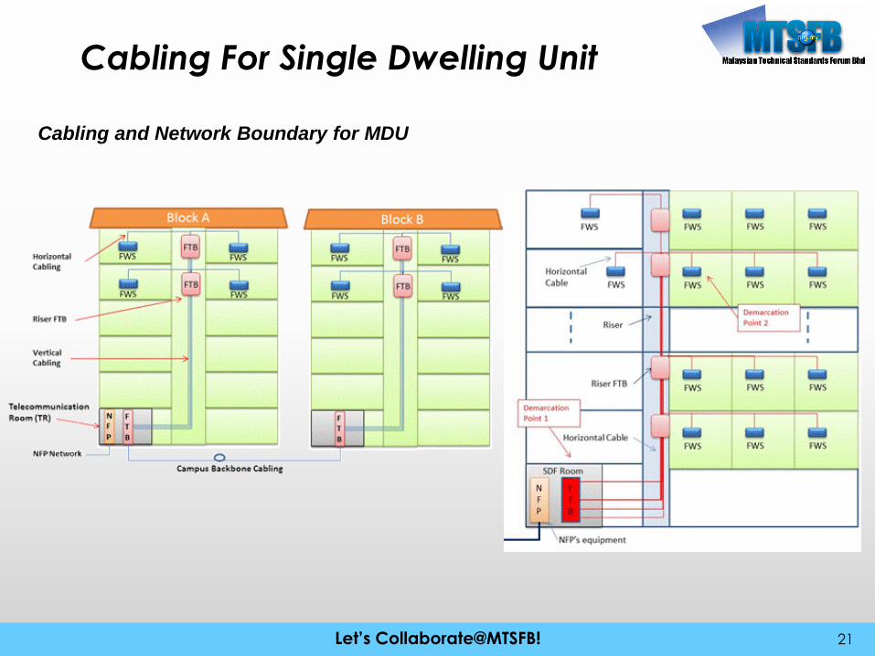
Cabling and Network Boundary for MDU

Let’s Collaborate@MTSFB!Let’s Collaborate@MTSFB!
Cabling For Multi Dwelling Unit
22
Horizontal Cabling Planning
Number of minimum fibre core = 2 x Number Unit in the Building + 30% of Number of unit the Building
Example:
Number Unit in building = 100 units
Min. number of fibre core in Backbone Cable = (2 x 100) + 30% (100)
= 200 + 30
= 230 cores
Number of minimum fibre core = 2 x Number Unit in Linked Building + (30% of total unit in Linked
Building)
Example:
There are 2 blocks in the development area which are Block A and Block B.
Number Unit in Block A (The main building) = 100
Number Unit in Block B (The subsequent building) = 100
Min. number of fibre core in Backbone Cable = (2 x 100) + 30% (100)
= 200 + 30
= 230 cores
Campus Backbone Cabling

Let’s Collaborate@MTSFB!Let’s Collaborate@MTSFB!
Design 1 of Internal Cabling Design for High Rise Building –
High Capacity Vertical
23
1
2
3
4
5
6
7
8
9
10
11
12
GMainFTB
FTB
8 Unit/Floor
8 Unit/Floor
8 Unit/Floor
8 Unit/Floor
8 Unit/Floor
8 Unit/Floor
8 Unit/Floor
8 Unit/Floor
8 Unit/Floor
8 Unit/Floor
8 Unit/Floor
8 Unit/Floor
FTB
FWS FWS FWS
2c 2c 2c
8unit x 2c
Vertical cable= 2 unit x 96 Cores= cores
96 cores
Main FTB Capacity= 8 Unit x 12 Floor x 2 cores= 192 Termination
Sample Bill of Material1. Vertical Cable & Horizontal = 96Core x 22. Riser FTB with 16 termination = 12 unit3. Main FTB with 192 termination = 1 unit
FTB
FTB
FTB
FTB
FTB
FTB
FTB
FTB
FTB
FTB
FTB
Floor FTB with 16 termination withSC/UPC ConnectorOr Splice type
Vertical CableCore #1-16 joint with Horizontal CableCore #17-96 pass thru to above floor
Horizontal CableEach unit FWS = 2 cores in single cable or separate
Let’s Collaborate@MTSFB!Let’s Collaborate@MTSFB!
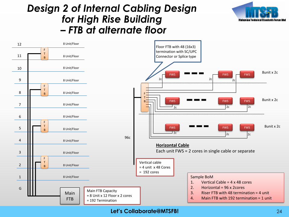
Design 2 of Internal Cabling Design for High Rise Building– FTB at alternate floor
24
1
2
3
4
5
6
7
8
9
10
11
12
GMainFTB
FTB
FTB
FTB
FTB
8 Unit/Floor
8 Unit/Floor
8 Unit/Floor
8 Unit/Floor
8 Unit/Floor
8 Unit/Floor
8 Unit/Floor
8 Unit/Floor
8 Unit/Floor
8 Unit/Floor
8 Unit/Floor
8 Unit/Floor
FTB
FWS FWS FWS
FWS FWS FWS
FWS FWS FWS
2c 2c 2c
2c 2c 2c
2c2c2c
8unit x 2c
8unit x 2c
8unit x 2c
96c
Main FTB Capacity= 8 Unit x 12 Floor x 2 cores= 192 Termination
Sample BoM1. Vertical Cable = 4 x 48 cores2. Horizontal = 96 x 2cores3. Riser FTB with 48 termination = 4 unit4. Main FTB with 192 termination = 1 unit
Horizontal CableEach unit FWS = 2 cores in single cable or separate
Floor FTB with 48 (16x3) termination with SC/UPC Connector or Splice type
Vertical cable= 4 unit x 48 Cores= 192 cores
Let’s Collaborate@MTSFB!Let’s Collaborate@MTSFB!
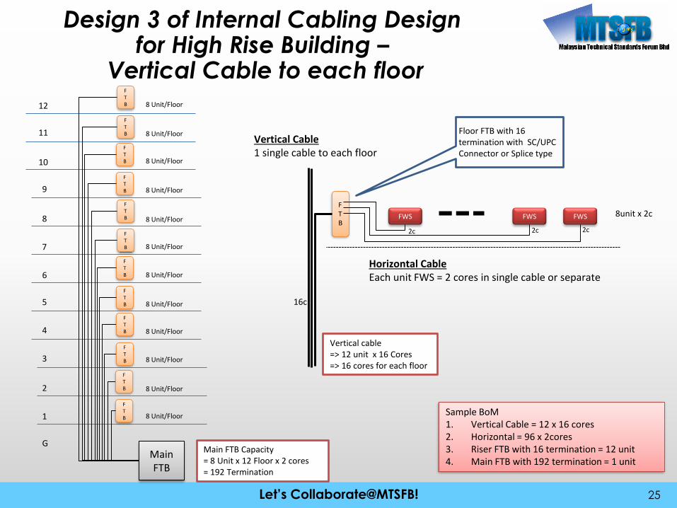
Design 3 of Internal Cabling Design for High Rise Building –
Vertical Cable to each floor
25
1
2
3
4
5
6
7
8
9
10
11
12
GMainFTB
FTB
8 Unit/Floor
8 Unit/Floor
8 Unit/Floor
8 Unit/Floor
8 Unit/Floor
8 Unit/Floor
8 Unit/Floor
8 Unit/Floor
8 Unit/Floor
8 Unit/Floor
8 Unit/Floor
8 Unit/Floor
FTB
FWS FWS FWS
2c 2c 2c
8unit x 2c
Vertical cable=> 12 unit x 16 Cores=> 16 cores for each floor
16c
Main FTB Capacity= 8 Unit x 12 Floor x 2 cores= 192 Termination
Sample BoM1. Vertical Cable = 12 x 16 cores2. Horizontal = 96 x 2cores3. Riser FTB with 16 termination = 12 unit4. Main FTB with 192 termination = 1 unit
FTB
FTB
FTB
FTB
FTB
FTB
FTB
FTB
FTB
FTB
FTB
Horizontal CableEach unit FWS = 2 cores in single cable or separate
Floor FTB with 16 termination with SC/UPC Connector or Splice type
Vertical Cable1 single cable to each floor

Let’s Collaborate@MTSFB!Let’s Collaborate@MTSFB!
Design 4 of Internal Cabling Design for High Rise Building –
Vertical Cable to each floor
26
1
2
3
4
5
6
GMainFTB
FTB
8 Unit/Floor
8 Unit/Floor
8 Unit/Floor
8 Unit/Floor
8 Unit/Floor
8 Unit/Floor
FTB
FWS FWS FWS
2c 2c 2c
8unit x 2c
Vertical cable=> 48 unit x 2 Cores 16 cores for each floor 8 x 2C cable for each floor
8 x 2C
Main FTB Capacity= 8 Unit x 6 Floor x 2 cores= 96 Termination
Sample BoM1. Vertical Cable = 48 x 2cores cable2. Horizontal = 48 x 2 cores cable3. Riser FTB with 16 termination = 6 unit4. Main FTB with 96 termination = 1 unit
FTB
FTB
FTB
FTB
Horizontal CableEach unit FWS = 2 cores in single cable or separate
Floor FTB with 16 termination with SC/UPC Connector or Splice typeVertical Cable
8 x 2C single cable to each floor
FTB
Let’s Collaborate@MTSFB!Let’s Collaborate@MTSFB!
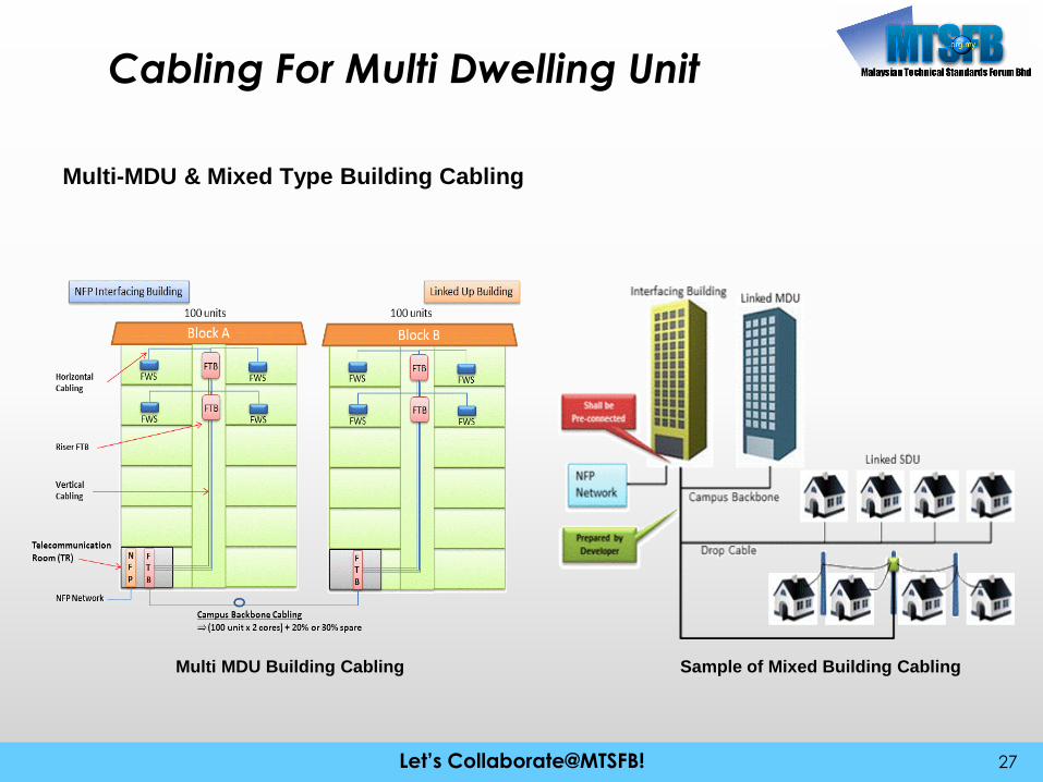
Cabling For Multi Dwelling Unit
27
Multi-MDU & Mixed Type Building Cabling
Multi MDU Building Cabling Sample of Mixed Building Cabling

Let’s Collaborate@MTSFB!Let’s Collaborate@MTSFB!
Cabling For Multi Dwelling Unit
28
Specification of MDU Internal Cabling
Cable Cabling Portion Specification
Campus Backbone Main TR to other building TR Single Mode ITU-T G.652 D
Indoor and Underground Cable
Vertical Cable FTB at TR to each Floor Riser’s
FTB
Single Mode ITU-T G.652 D or
ITU-T G.657 A
Indoor Cable
Horizontal Cable Floor Riser’s FTB to Individual
Unit Premise FWS
Single Mode ITU-T G.657 A
Indoor Cable
Drop Cable SDU in Mixed Building Single Mode ITU-T G.657 A
Underground Cable
Possible Vertical Fibre Cable design – Loose Tube Possible Vertical Fibre Cable design – Ribbon

Let’s Collaborate@MTSFB!Let’s Collaborate@MTSFB!
Cabling For Multi Dwelling Unit
29
Fibre Optic Cable (Foc)
• Fibre Optic Cable Construction
• Strength members:
• Cable Jacket –
• Indoor cables
• Protection Against Water and Moisture –
• Protection Against Crushing or Rodent
Penetration
Type of Cable
• Tight Buffer Cable Types -
• Distribution cables: Distribution Cable
• Breakout cables:
• Loose tube cables
• Ribbon Cable: Ribbon
• Armored Cable:
• Aerial Cables
• Air-Blown Fibre:
Cable Color Codes

Let’s Collaborate@MTSFB!Let’s Collaborate@MTSFB!
Cabling For Multi Dwelling Unit
30
Power Link Budget Calculation and Estimation
No. Item Loss
1 Fibre Optic Cable (FOC) measured at 1310nm wavelength 0.4dB/KM
2 Fusion Splice Loss 0.1dB
3 Mechanical Splice Loss 0.5dB
4 Factory fitted SC-UPC connector 0.2dB
5 Field Assemble SC-UPC (FA-SC) connector 0.5dB
6 Splice on Connector (SOC) 0.3dB
Attenuation Loss Reference
Location Item Detail
Campus Backbone cable Cable (1310 =0.4 db/KM)*
Campus Backbone Cable (200m) =
0.08 dB
Telecommunicatin Room FTB Connector Loss = 0.5 dB
Cable (1310 =0.4 db/KM)* Vertical Cable (100m) = 0.04 dB
FTB Mechanical Splice + Adaptor = 0.7 dB
Horizontal Trunking Cable (1310 =0.4 db/KM)* Vertical Cable (50m) = 0.02 dB
Inside Premise FWS FA-SC Connector = 0.7 dB
Other Marginal Loss Others Other loss = 0.16
Total = 2.2 dB
Riser
Cabling Power Link Budget for MDU

Let’s Collaborate@MTSFB!Let’s Collaborate@MTSFB!
Labelling and Tagging
31
Tagging Material and Specification
Sample of recommended Tagging SystemCable Tag
Labeling and Tagging for SDU with U/G Access

Let’s Collaborate@MTSFB!Let’s Collaborate@MTSFB!
Labelling and Tagging
32
Labeling and Tagging for Premise Internal Cabling
Labeling and tagging for Premise Internal Cabling
Color Code for 2 Cores of Drop Cable
Labeling and Tagging for MDU’s Cabling
Let’s Collaborate@MTSFB!Let’s Collaborate@MTSFB!
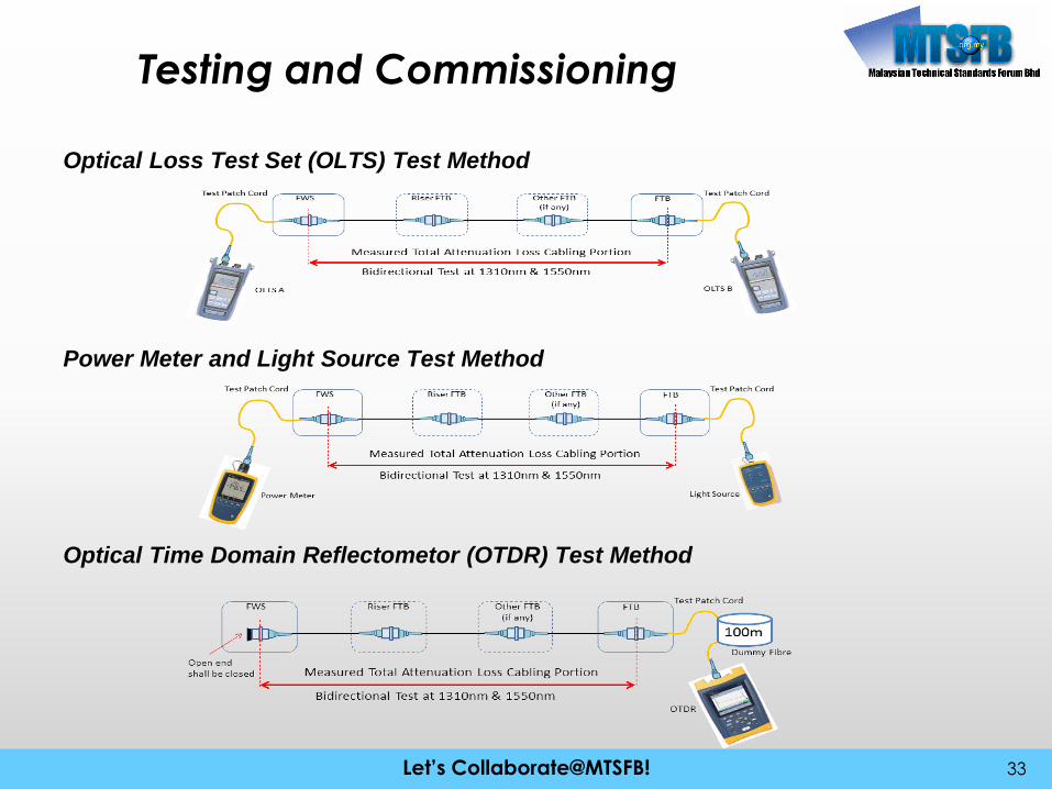
Testing and Commissioning
33
Optical Loss Test Set (OLTS) Test Method
Power Meter and Light Source Test Method
Optical Time Domain Reflectometor (OTDR) Test Method
Let’s Collaborate@MTSFB!Let’s Collaborate@MTSFB!
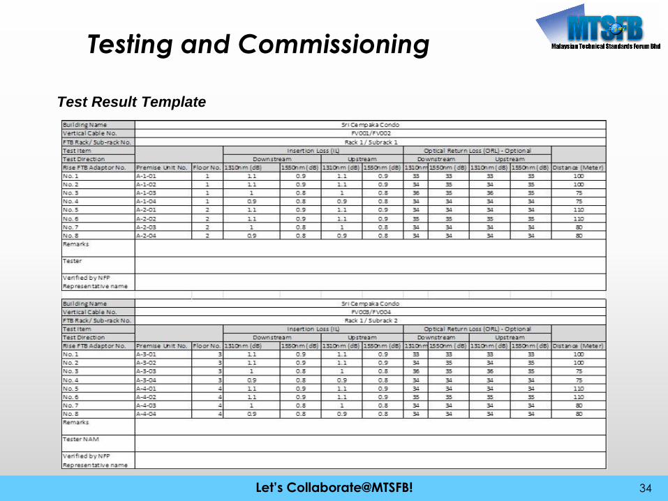
Testing and Commissioning
34
Test Result Template

Let’s Collaborate@MTSFB!Let’s Collaborate@MTSFB!
Testing and Commissioning
35
Let’s Collaborate@MTSFB!Let’s Collaborate@MTSFB!
Testing and Commissioning
36
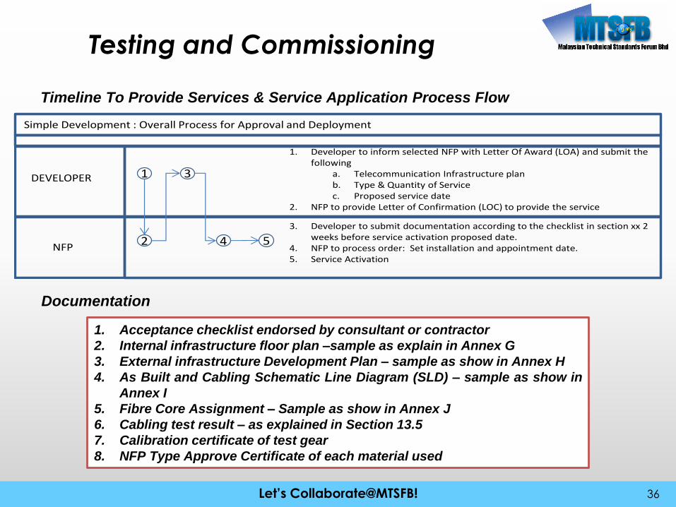
Timeline To Provide Services & Service Application Process Flow
Simple Development : Overall Process for Approval and Deployment
DEVELOPER
NFP
1. Developer to inform selected NFP with Letter Of Award (LOA) and submit the following
a. Telecommunication Infrastructure planb. Type & Quantity of Servicec. Proposed service date
2. NFP to provide Letter of Confirmation (LOC) to provide the service
1
2
3
4 5
3. Developer to submit documentation according to the checklist in section xx 2 weeks before service activation proposed date.
4. NFP to process order: Set installation and appointment date.5. Service Activation
Documentation
1. Acceptance checklist endorsed by consultant or contractor
2. Internal infrastructure floor plan –sample as explain in Annex G
3. External infrastructure Development Plan – sample as show in Annex H
4. As Built and Cabling Schematic Line Diagram (SLD) – sample as show in
Annex I
5. Fibre Core Assignment – Sample as show in Annex J
6. Cabling test result – as explained in Section 13.5
7. Calibration certificate of test gear
8. NFP Type Approve Certificate of each material used
Let’s Collaborate@MTSFB!Let’s Collaborate@MTSFB!
Issue and Concern
37
• Quality of the material – Type approval by TM & SIRIM
• Competency of the cabling contractor

Let’s Collaborate@MTSFB!Let’s Collaborate@MTSFB! 38
Let’s Collaborate@MTSFB!Let’s Collaborate@MTSFB! 39

Let’s Collaborate@MTSFB!Let’s Collaborate@MTSFB! 40

Let’s Collaborate@MTSFB!Let’s Collaborate@MTSFB! 41