technical support manual split system air conditioner n4a3
TRANSCRIPT

421 04 5100 01 October 2006
TECHNICAL SUPPORT MANUALSplit System Air Conditioner
N4A3
DANGER, WARNING, CAUTION, andNOTEThe signal words DANGER, WARNING,CAUTION, and NOTE are used to identify levels ofhazard seriousness. The signal word DANGER isonly used on product labels to signify an immediatehazard. The signal words WARNING, CAUTION,and NOTE will be used on product labels andthroughout this manual and other manuals that mayapply to the product.
DANGER − Immediate hazards which will result insevere personal injury or death.
WARNING − Hazards or unsafe practices whichcould result in severe personal injury or death.
CAUTION − Hazards or unsafe practices whichmay result in minor personal injury or product orproperty damage.
NOTE − Used to highlight suggestions which will result in enhanced installation, reliability,or operation.
Signal Words in Manuals
The signal word WARNING is used throughout thismanual in the following manner:
The signal word CAUTION is used throughout thismanual in the following manner:
Signal Words on Product Labeling
Signal words are used in combination with colorsand/or pictures on product labels.
WARNING
Safety Labeling and Signal Words
!
! CAUTION
WARNING
TABLE OF CONTENTSWiring Diagrams 2 − 3. . . . . . . . . . . . . . . . . . . . . . . . . . . .
Charging Chart 4. . . . . . . . . . . . . . . . . . . . . . . . . . . . . . . . .
Tech Labels (Expanded Data) and Multipying Factors 5 − 11. . . . . . . . . . . . . . . . . . . . . . . . . .
Condenser Only Data 12 − 15. . . . . . . . . . . . . . . . . . . . . .
Exploded Drawings 16 − 18. . . . . . . . . . . . . . . . . . . . . . . .
Parts List 19 − 21. . . . . . . . . . . . . . . . . . . . . . . . . . . . . . . . .
Model Number Identification 22. . . . . . . . . . . . . . . . . . . .
! WARNING
DEATH, PERSONAL INJURY, AND/OR PROPERTYDAMAGE HAZARD
Failure to carefully read and follow this warningcould result in equipment malfunction, propertydamage, personal injury and/or death.
Installation or repairs made by unqualified per-sons could result in equipment malfunction, prop-erty damage, personal injury and/or death.
The information contained in this manual is in-tended for use by a qualified service technician fa-miliar with safety procedures and equipped withthe proper tools and test instruments.
Installation must conform with local buildingcodes and with the National Electrical CodeNFPA70 current edition or Canadian ElectricalCode Part 1 CSA C.22.1.

TE
CH
NIC
AL
SU
PP
OR
T M
AN
UA
LS
plit S
ystem A
ir Co
nd
ition
er: N4A
3
2421 04 5100 01
Model Sizes: 18, 24, 30, 36, 42, 48
1. Symbols are electrical representation only.
2. Compressor and fan motor furnished with inherent thermal protection.
3. To be wired in accordance with National Electric N.E.C. and local codes.
4. N.E.C. class 2, 24 V circuit, min. 40 VA required, 60 VA on units installed with LLS.
5. Use copper conductors only. Use conductors suitable for at least 75°C (167°F).
6. Connection for typical cooling only thermostat. For other arrangements see installation instructions.
7. If indoor section has a transformer with a grounded secondary, connect the grounded side to the BRN/YEL lead.
8. When start capacitor and relay are installed, start thermistor (PTC) is not used.
9. CH not used on all units.
10. If any of the original wire, as supplied, must be replaced, use the same or equivalent wire.
11. Check all electrical connections inside control box for tightness.
12. Do not attempt to operate unit until service valves have been opened.
13. Do not rapid cycle compressor. Compressor must be off 3 minutes to allow pressures to equalize between high and low side before starting.
14. Wire not present if HPS, LPS or CTD are used.

TE
CH
NIC
AL
SU
PP
OR
T M
AN
UA
LS
plit S
ystem A
ir Co
nd
ition
er: N4A
3
421 04 5100 013
Model Size: 60
1. Symbols are electrical representation only.
2. Compressor and fan motor furnished with inherent thermal protection.
3. To be wired in accordance with National Electric N.E.C. and local codes.
4. N.E.C. class 2, 24 V circuit, min. 40 VA required, 60 VA on units installed with LLS.
5. Use copper conductors only. Use conductors suitable for at least 75°C (167°F).
6. Connection for typical cooling only thermostat. For other arrangements see installation instructions.
7. If indoor section has a transformer with a grounded secondary, connect the grounded side to the BRN/YEL lead.
8. When start capacitor and relay are installed, start thermistor (PTC) is not used.
9. CH not used on all units.
10. If any of the original wire, as supplied, must be replaced, use the same or equivalent wire.
11. Check all electrical connections inside control box for tightness.
12. Do not attempt to operate unit until service valves have been opened.
13. Do not rapid cycle compressor. Compressor must be off 3 minutes to allow pressures to equalize between high and low side before starting.
14. Wire not present if HPS, LPS or CTD are used.

TECHNICAL SUPPORT MANUAL Split System Air Conditioner: N4A3
4 421 04 5100 01
R−410A CHARGING CHART� Find the required Subcooling Temperature on the unit Rating Plate. Use the closest column on the chart below
(6, 8, 10, 12, 14 or 16) .
� Add or remove refrigerant until both the Liquid Line Temperature and Liquid Pressure agree with chart data.
Measured Liquid Pressure (psig)
Rating Plate (required) Subcooling Temperature (°F)
6 8 10 12 14 16
Required Liquid Line Temperature (°F)
189 60 58 56 54 52 50
195 62 60 58 56 54 52
202 64 62 60 58 56 54
208 66 64 62 60 58 56
215 68 66 64 62 60 58
222 70 68 66 64 62 60
229 72 70 68 66 64 62
236 74 72 70 68 66 64
243 76 74 72 70 68 66
251 78 76 74 72 70 68
259 80 78 76 74 72 70
266 82 80 78 76 74 72
274 84 82 80 78 76 74
283 86 84 82 80 78 76
291 88 86 84 82 80 78
299 90 88 86 84 82 80
308 92 90 88 86 84 82
317 94 92 90 88 86 84
326 96 94 92 90 88 86
335 98 96 94 92 90 88
345 100 98 96 94 92 90
354 102 100 98 96 94 92
364 104 102 100 98 96 94
374 106 104 102 100 98 96
384 108 106 104 102 100 98
395 110 108 106 104 102 100
406 112 110 108 106 104 102
416 114 112 110 108 106 104
427 116 114 112 110 108 106
439 118 116 114 112 110 108
450 120 118 116 114 112 110
462 122 120 118 116 114 112
474 124 122 120 118 116 114
486 126 124 122 120 118 116
499 128 126 124 122 120 118
511 130 128 126 124 122 120

TECHNICAL SUPPORT MANUAL Split System Air Conditioner: N4A3
421 04 5100 01 5
N4A318AKA
N4A318GKA
N4A318*KA Outdoor With ED*4X18B** Indoor Cooling
Outdoor Ambient Temperature − °F, Dry Bulb
75 85 95 105 115
Entering Indoor Temperature − °F, Wet BulbCFM 72 67 62 57 72 67 62 57 72 67 62 57 72 67 62 57 72 67 62 57
525
MBh † 20.46 18.79 17.27 16.78 19.55 17.95 16.49 16.15 18.59 17.05 15.68 15.48 17.62 16.12 14.83 14.77 16.57 15.13 14.00 14.00
S/T ‡ 0.53 0.71 0.91 1.00 0.53 0.72 0.93 1.00 0.54 0.73 0.95 1.00 0.55 0.75 0.98 1.00 0.56 0.78 1.00 1.00
AMPS^ 5.28 5.30 5.32 5.33 5.93 5.95 5.97 5.97 6.65 6.67 6.68 6.69 7.45 7.46 7.47 7.47 8.31 8.33 8.34 8.34
HI PR 272 269 266 265 314 310 307 307 360 356 353 353 411 407 403 403 466 462 459 459
LO PR 153 140 128 125 155 142 131 128 158 144 133 131 160 147 136 135 163 149 139 139
600
MBh † 20.80 19.10 17.65 17.46 19.83 18.23 16.87 16.79 18.83 17.30 16.06 16.07 17.83 16.35 15.32 15.32 16.76 15.33 14.51 14.51
S/T ‡ 0.54 0.74 0.96 1.00 0.55 0.75 0.98 1.00 0.56 0.77 1.00 1.00 0.57 0.79 1.00 1.00 0.58 0.82 1.00 1.00
AMPS^ 5.40 5.42 5.44 5.44 6.05 6.07 6.09 6.09 6.77 6.79 6.80 6.80 7.56 7.58 7.59 7.59 8.43 8.45 8.45 8.45
HI PR 273 270 267 266 315 311 308 308 361 357 354 354 412 408 405 405 467 463 461 461
LO PR 157 143 132 131 159 145 134 134 161 148 137 137 163 150 141 141 166 152 145 145
675
MBh † 21.04 19.33 18.01 18.01 20.02 18.43 17.30 17.30 19.00 17.48 16.54 16.54 17.97 16.51 15.76 15.76 16.88 15.48 14.92 14.92
S/T ‡ 0.56 0.77 0.99 1.00 0.57 0.79 1.00 1.00 0.58 0.81 1.00 1.00 0.59 0.83 1.00 1.00 0.61 0.86 1.00 1.00
AMPS^ 5.52 5.54 5.55 5.55 6.17 6.19 6.20 6.20 6.88 6.90 6.92 6.92 7.68 7.70 7.70 7.70 8.55 8.56 8.57 8.57
HI PR 274 270 268 268 316 312 310 310 362 358 356 356 412 408 406 406 467 463 462 462
LO PR 159 146 136 136 161 148 139 139 164 150 142 142 166 152 146 146 168 155 150 150
† Total capacities are net (I.D. blower heat substracted) system capacities based on 25’ line set.If additional tubing length and/or indoor unit is located above outdoor unit, a slight variation in capacity may occur.
^ System amps are total of indoor and outdoor amps.‡ Chart data is for 80° F indoor dry bulb. For indoor db temperatures other than 80° F, measure Indoor db and Indoor CFM, and plug these intothe formula below. Measure outdoor db and indoor wet bulb, apply these to the chart above, find MBh and S/T, and plug these into the formulabelow. (Note: if indoor db is the only thing changing, total capacity, MBh, stays the same.)
Sensible Capacity at Indoor db LOWER than 80 °F = ( MBh x S/T ) −( 80 − Indoor db ) x 835 x Indoor CFM
1000( )Sensible Capacity at Indoor db HIGHER than 80 °F = ( MBh x S/T ) +
( Indoor db − 80 ) x 835 x Indoor CFM
1000( )Multiplying Factors for other Indoor Combinations
IndoorModel
FurnaceModel
Capac.(MBh)
Power(AMPS)
IndoorModel
FurnaceModel
Capac.(MBh)
Power(AMPS)
IndoorModel
FurnaceModel
Capac.(MBh)
Power(AMPS)
> ED*4X18B** 1.00 1.00 EL*24B**** 0.97 1.00 FS(M,U)4X18**** 1.01 1.03
ED*4X18B** MV08B15**** 1.03 0.97 EMH24F**** 0.97 1.03 FS(M,U)4X24**** 1.01 1.04
ED*4X24B** 1.02 1.02 EP*18B**** 0.93 1.03 FEM4X18**** 1.02 0.96
ED*4X24B** MV08B15**** 1.04 0.98 EP*18B**** MV08B15**** 0.94 0.93 FEM4X24**** 1.03 0.97
ED*4X24F** 1.02 1.02 EP*24B**** 0.97 1.03 EBP18**** 0.97 1.01
ED*4X24F** MV12F19**** 1.04 0.98 EP*24B**** MV08B15**** 0.99 0.95 EBP24**** 1.01 1.02
EMA4X24D** 1.02 1.02 EP*24F**** 0.97 1.03 FWM18**** 0.97 0.98
EHD4X24A** 1.02 1.02 EP*24F**** MV12F19**** 0.98 0.92 FWM24**** 1.01 1.03
EHD4X24A** *9MPV050 1.03 0.99 EPP024**** 0.90 1.00 EBXX18**** 1.01 1.01
EHD4X24A** MV08B15**** 1.03 0.97 EXX*24B**** 1.02 1.02 EBXX24**** 1.02 1.02
EHD4X24A** MV12F19**** 1.03 0.97 EXX*24B**** MV08B15**** 1.05 0.99 EBV24**** 1.03 0.97
EL*18B**** 0.93 1.03 EXX*24F**** 1.02 1.02 EBV36**** 1.03 0.96
EL*18B**** MV08B15**** 0.94 0.93 EXX*24F**** MV12F19**** 1.05 0.96
> Indicates Tested Indoor Model

TECHNICAL SUPPORT MANUAL Split System Air Conditioner: N4A3
6 421 04 5100 01
N4A324AKA
N4A324GKA
N4A324*KA Outdoor With ED*4X24B** Indoor Cooling
Outdoor Ambient Temperature − °F, Dry Bulb
75 85 95 105 115
Entering Indoor Temperature − °F, Wet BulbCFM 72 67 62 57 72 67 62 57 72 67 62 57 72 67 62 57 72 67 62 57
700
MBh † 27.16 24.77 22.65 22.03 25.93 23.64 21.63 21.21 24.63 22.44 20.56 20.33 23.25 21.17 19.45 19.39 21.76 19.82 18.38 18.38
S/T ‡ 0.53 0.71 0.92 1.00 0.53 0.72 0.94 1.00 0.54 0.74 0.96 1.00 0.55 0.76 0.99 1.00 0.56 0.78 1.00 1.00
AMPS^ 6.99 7.00 7.00 7.00 7.86 7.87 7.87 7.88 8.83 8.83 8.84 8.84 9.89 9.89 9.89 9.89 11.04 11.04 11.04 11.04
HI PR 291 286 282 280 334 329 324 323 381 375 371 370 432 427 422 422 488 482 478 478
LO PR 152 139 127 124 154 141 130 127 156 143 132 131 159 146 135 134 162 148 139 139
800
MBh † 27.64 25.22 23.18 22.95 26.36 24.04 22.15 22.07 25.00 22.80 21.12 21.13 23.57 21.49 20.12 20.13 22.02 20.09 19.04 19.04
S/T ‡ 0.54 0.74 0.96 1.00 0.55 0.76 0.98 1.00 0.56 0.77 1.00 1.00 0.57 0.80 1.00 1.00 0.59 0.83 1.00 1.00
AMPS^ 7.14 7.15 7.16 7.16 8.02 8.02 8.03 8.03 8.98 8.99 8.99 8.99 10.04 10.04 10.05 10.05 11.19 11.19 11.20 11.20
HI PR 292 287 283 283 335 330 326 325 382 377 373 373 434 428 424 424 489 483 480 480
LO PR 155 142 131 130 157 144 133 133 160 146 136 136 162 149 140 140 164 151 144 144
900
MBh † 28.00 25.56 23.69 23.71 26.67 24.35 22.77 22.77 25.27 23.07 21.78 21.78 23.79 21.72 20.72 20.72 22.19 20.28 19.57 19.57
S/T ‡ 0.56 0.77 1.00 1.00 0.57 0.79 1.00 1.00 0.58 0.81 1.00 1.00 0.59 0.84 1.00 1.00 0.61 0.87 1.00 1.00
AMPS^ 7.30 7.30 7.31 7.31 8.17 8.18 8.18 8.18 9.14 9.14 9.14 9.14 10.19 10.20 10.20 10.20 11.35 11.35 11.35 11.35
HI PR 293 288 284 284 336 331 327 327 383 378 375 375 435 429 426 426 490 484 482 482
LO PR 158 145 135 135 160 147 138 138 162 149 141 141 164 151 145 145 167 154 149 149
† Total capacities are net (I.D. blower heat substracted) system capacities based on 25’ line set.If additional tubing length and/or indoor unit is located above outdoor unit, a slight variation in capacity may occur.
^ System amps are total of indoor and outdoor amps.‡ Chart data is for 80° F indoor dry bulb. For indoor db temperatures other than 80° F, measure Indoor db and Indoor CFM, and plug these intothe formula below. Measure outdoor db and indoor wet bulb, apply these to the chart above, find MBh and S/T, and plug these into the formulabelow. (Note: if indoor db is the only thing changing, total capacity, MBh, stays the same.)
Sensible Capacity at Indoor db LOWER than 80 °F = ( MBh x S/T ) −( 80 − Indoor db ) x 835 x Indoor CFM
1000( )Sensible Capacity at Indoor db HIGHER than 80 °F = ( MBh x S/T ) +
( Indoor db − 80 ) x 835 x Indoor CFM
1000( )Multiplying Factors for other Indoor Combinations
IndoorModel
FurnaceModel
Capac.(MBh)
Power(AMPS)
IndoorModel
FurnaceModel
Capac.(MBh)
Power(AMPS)
IndoorModel
FurnaceModel
Capac.(MBh)
Power(AMPS)
> ED*4X24B** 1.00 1.00 EHD4X30A** 1.01 1.01 EP*30F**** *9MPV050 0.95 0.95
ED*4X24B** *8MPV050 1.00 0.98 EHD4X30A** *8MPV050 1.01 0.99 EP*30F**** *9MPV075 0.95 0.95
ED*4X24B** MV08B15**** 1.00 0.96 EHD4X30A** *9MPV050 1.01 0.99 EP*30F**** MV12F19**** 0.96 0.94
ED*4X24F** 1.01 1.01 EHD4X30A** *9MPV075 1.00 0.96 EXX*24B**** 0.99 1.01
ED*4X24F** *9MPV050 1.00 0.96 EHD4X30A** *9MPV100 1.03 0.98 EXX*24B**** *8MPV050 0.99 0.99
ED*4X24F** *9MPV075 0.99 0.97 EHD4X30A** MV08B15**** 1.02 0.96 EXX*24B**** MV08B15**** 0.99 0.95
ED*4X24F** MV12F19**** 1.01 0.95 EHD4X30A** MV12F19**** 1.02 0.96 EXX*24F**** 0.99 1.01
ED*4X30B** 1.02 1.02 EHD4X30A** MV16J22**** 1.04 0.97 EXX*24F**** *8MPV075 1.00 0.98
ED*4X30B** *8MPV050 1.00 0.98 EHD4X30A** MV20N26**** 1.03 0.96 EXX*24F**** *9MPV050 0.98 0.96
ED*4X30B** MV08B15**** 1.01 0.95 EL*24B**** 0.93 1.01 EXX*24F**** *9MPV075 0.99 0.97
ED*4X30F** 1.02 1.02 EL*24B**** *8MPV050 0.93 0.97 EXX*24F**** MV12F19**** 0.99 0.95
ED*4X30F** *9MPV050 1.01 0.96 EL*24B**** MV08B15**** 0.94 0.92 EMH24F**** 0.93 1.01
ED*4X30F** *9MPV075 1.01 0.96 EL*30B**** 0.95 1.01 EMH30F**** 0.95 1.01
ED*4X30F** MV12F19**** 1.01 0.95 EL*30B**** *8MPV050 0.95 0.95 EPP030**** 0.92 1.01
EMA4X24D** 1.00 1.00 EL*30B**** MV08B15**** 0.95 0.93 FS(M,U)4X24**** 0.99 1.01
EHD4X24A** 1.01 1.01 EP*24B**** 0.93 1.01 FS(M,U)4X30**** 1.00 1.00
EHD4X24A** *8MPV050 1.00 0.98 EP*24B**** *8MPV050 0.93 0.96 FEM4X24**** 1.01 0.96
EHD4X24A** *8MPV075 1.02 1.00 EP*24B**** MV08B15**** 0.94 0.92 FEM4X30**** 1.02 0.97
EHD4X24A** *8MPV100 1.03 0.98 EP*24F**** 0.93 1.01 EBP24**** 0.98 1.01
EHD4X24A** *8MPV125 1.02 0.97 EP*24F**** *9MPV050 0.93 0.93 EBP30**** 0.99 1.00
EHD4X24A** *9MPV050 1.02 1.00 EP*24F**** *9MPV075 0.93 0.93 FWM24**** 0.97 1.02
EHD4X24A** *9MPV075 1.00 0.98 EP*24F**** MV12F19**** 0.94 0.92 FWM30**** 0.99 1.02
EHD4X24A** *9MPV100 1.02 0.97 EP*30B**** 0.95 1.01 EBXX18**** 0.98 1.01
EHD4X24A** MV08B15**** 1.02 0.96 EP*30B**** *8MPV050 0.95 0.95 EBXX24**** 0.99 1.00
EHD4X24A** MV12F19**** 1.00 0.94 EP*30B**** MV08B15**** 0.95 0.93 EBV24**** 1.02 0.97
EHD4X24A** MV16J22**** 1.02 0.96 EP*30F**** 0.95 1.01 EBV36**** 1.03 0.98
EHD4X24A** MV20N26**** 1.01 0.95
> Indicates Tested Indoor Model
TECHNICAL SUPPORT MANUAL Split System Air Conditioner: N4A3
421 04 5100 01 7
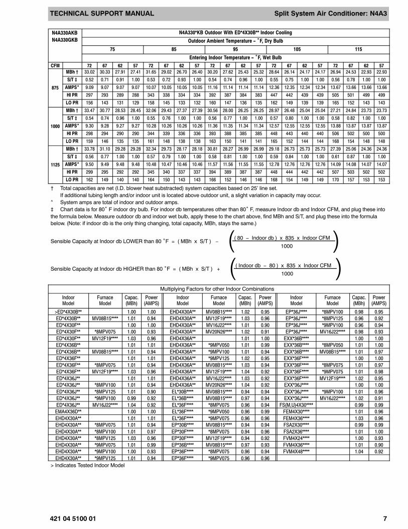
N4A330AKB
N4A330GKB
N4A330*KB Outdoor With ED*4X30B** Indoor Cooling
Outdoor Ambient Temperature − °F, Dry Bulb
75 85 95 105 115
Entering Indoor Temperature − °F, Wet Bulb
CFM 72 67 62 57 72 67 62 57 72 67 62 57 72 67 62 57 72 67 62 57
875
MBh † 33.02 30.33 27.91 27.41 31.65 29.02 26.70 26.40 30.20 27.62 25.43 25.32 28.64 26.14 24.17 24.17 26.94 24.53 22.93 22.93
S/T ‡ 0.52 0.71 0.91 1.00 0.53 0.72 0.93 1.00 0.54 0.74 0.96 1.00 0.55 0.75 1.00 1.00 0.56 0.78 1.00 1.00
AMPS^ 9.09 9.07 9.07 9.07 10.07 10.05 10.05 10.05 11.16 11.14 11.14 11.14 12.36 12.35 12.34 12.34 13.67 13.66 13.66 13.66
HI PR 297 293 289 288 343 338 334 334 392 387 384 383 447 442 439 439 505 501 499 499
LO PR 156 143 131 129 158 145 133 132 160 147 136 135 162 149 139 139 165 152 143 143
1000
MBh † 33.47 30.77 28.53 28.45 32.06 29.43 27.37 27.39 30.56 28.00 26.25 26.25 28.97 26.48 25.04 25.04 27.21 24.84 23.73 23.73
S/T ‡ 0.54 0.74 0.96 1.00 0.55 0.76 1.00 1.00 0.56 0.77 1.00 1.00 0.57 0.80 1.00 1.00 0.58 0.82 1.00 1.00
AMPS^ 9.30 9.28 9.27 9.27 10.28 10.26 10.26 10.26 11.36 11.35 11.34 11.34 12.57 12.55 12.55 12.55 13.88 13.87 13.87 13.87
HI PR 298 294 290 290 344 339 336 336 393 388 385 385 448 443 440 440 506 502 500 500
LO PR 159 146 135 135 161 148 138 138 163 150 141 141 165 152 144 144 168 154 148 148
1125
MBh † 33.78 31.10 29.28 29.28 32.34 29.73 28.17 28.18 30.81 28.27 26.99 26.99 29.18 26.73 25.73 25.73 27.39 25.06 24.36 24.36
S/T ‡ 0.56 0.77 1.00 1.00 0.57 0.79 1.00 1.00 0.58 0.81 1.00 1.00 0.59 0.84 1.00 1.00 0.61 0.87 1.00 1.00
AMPS^ 9.50 9.49 9.48 9.48 10.48 10.47 10.46 10.46 11.57 11.56 11.55 11.55 12.78 12.76 12.76 12.76 14.09 14.08 14.07 14.07
HI PR 299 295 292 292 345 340 337 337 394 389 387 387 448 444 442 442 507 503 502 502
LO PR 162 149 140 140 164 150 143 143 166 152 146 146 168 154 149 149 170 157 153 153
† Total capacities are net (I.D. blower heat substracted) system capacities based on 25’ line set.If additional tubing length and/or indoor unit is located above outdoor unit, a slight variation in capacity may occur.
^ System amps are total of indoor and outdoor amps.‡ Chart data is for 80° F indoor dry bulb. For indoor db temperatures other than 80° F, measure Indoor db and Indoor CFM, and plug these intothe formula below. Measure outdoor db and indoor wet bulb, apply these to the chart above, find MBh and S/T, and plug these into the formulabelow. (Note: if indoor db is the only thing changing, total capacity, MBh, stays the same.)
Sensible Capacity at Indoor db LOWER than 80 °F = ( MBh x S/T ) −( 80 − Indoor db ) x 835 x Indoor CFM
1000( )Sensible Capacity at Indoor db HIGHER than 80 °F = ( MBh x S/T ) +
( Indoor db − 80 ) x 835 x Indoor CFM
1000( )Multiplying Factors for other Indoor Combinations
IndoorModel
FurnaceModel
Capac.(MBh)
Power(AMPS)
IndoorModel
FurnaceModel
Capac.(MBh)
Power(AMPS)
IndoorModel
FurnaceModel
Capac.(MBh)
Power(AMPS)
>ED*4X30B** 1.00 1.00 EHD4X30A** MV08B15**** 1.02 0.95 EP*36J**** *8MPV100 0.98 0.95
ED*4X30B** MV08B15**** 1.01 0.94 EHD4X30A** MV12F19**** 1.03 0.96 EP*36J**** *8MPV125 0.96 0.92
ED*4X30F** 1.00 1.00 EHD4X30A** MV16J22**** 1.01 0.90 EP*36J**** *9MPV100 0.96 0.94
ED*4X30F** *8MPV075 1.00 0.93 EHD4X30A** MV20N26**** 1.02 0.91 EP*36J**** MV16J22**** 0.98 0.93
ED*4X30F** MV12F19**** 1.03 0.96 EHD4X36A** 1.01 1.00 EXX*36B**** 1.00 1.00
ED*4X36B** 1.01 1.01 EHD4X36A** *9MPV050 1.01 0.99 EXX*36B**** *8MPV050 1.01 1.00
ED*4X36B** MV08B15**** 1.01 0.94 EHD4X36A** *9MPV100 1.01 0.94 EXX*36B**** MV08B15**** 1.01 0.97
ED*4X36F** 1.01 1.01 EHD4X36A** *9MPV125 1.02 0.95 EXX*36F**** 1.00 1.00
ED*4X36F** *8MPV075 1.01 0.94 EHD4X36A** MV08B15**** 1.03 0.94 EXX*36F**** *8MPV075 1.01 0.97
ED*4X36F** MV12F19**** 1.03 0.96 EHD4X36A** MV12F19**** 1.04 0.92 EXX*36F**** *9MPV075 1.01 0.98
ED*4X36J** 1.01 1.01 EHD4X36A** MV16J22**** 1.03 0.92 EXX*36F**** MV12F19**** 1.02 0.95
ED*4X36J** *8MPV100 1.01 0.94 EHD4X36A** MV20N26**** 1.04 0.92 EXX*36J**** 1.00 1.00
ED*4X36J** *8MPV125 1.01 0.90 EL*30B**** MV08B15**** 0.94 0.94 EXX*36J**** *9MPV100 1.01 0.96
ED*4X36J** *9MPV100 0.99 0.92 EL*36B**** MV08B15**** 0.97 0.94 EXX*36J**** MV16J22**** 1.02 0.91
ED*4X36J** MV16J22**** 1.04 0.92 EL*36F**** *8MPV075 0.96 0.94 FS(M,U)4X30**** 0.99 0.99
EMA4X36D** 1.00 1.00 EL*36F**** *9MPV050 0.96 0.99 FEM4X30**** 1.01 0.96
EHD4X30A** 1.01 1.01 EL*36F**** *9MPV075 0.96 0.96 FEM4X36**** 1.03 0.96
EHD4X30A** *8MPV075 1.01 0.94 EP*30B**** MV08B15**** 0.94 0.94 FSA2X30**** 0.99 0.99
EHD4X30A** *8MPV100 1.01 0.97 EP*30F**** *8MPV075 0.94 0.96 FSA2X36**** 1.01 1.00
EHD4X30A** *8MPV125 1.03 0.96 EP*30F**** MV12F19**** 0.94 0.92 FVM4X24**** 1.00 0.93
EHD4X30A** *9MPV075 1.01 0.99 EP*36B**** MV08B15**** 0.97 0.93 FVM4X36**** 1.01 0.90
EHD4X30A** *9MPV100 1.00 0.93 EP*36F**** *8MPV075 0.96 0.94 FVM4X48**** 1.04 0.92
EHD4X30A** *9MPV125 1.01 0.94 EP*36F**** *9MPV075 0.96 0.96
> Indicates Tested Indoor Model
TECHNICAL SUPPORT MANUAL Split System Air Conditioner: N4A3
8 421 04 5100 01
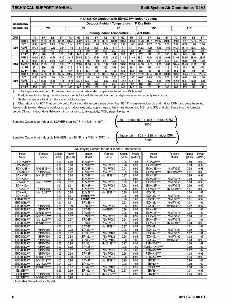
N4A336AKA
N4A336GKA
N4A336*KA Outdoor With ED*4X36F** Indoor Cooling
Outdoor Ambient Temperature − °F, Dry Bulb
75 85 95 105 115
Entering Indoor Temperature − °F, Wet BulbCFM 72 67 62 57 72 67 62 57 72 67 62 57 72 67 62 57 72 67 62 57
1050
MBh † 40.27 36.63 33.48 32.81 38.53 35.02 32.04 31.62 36.70 33.31 30.53 30.36 34.76 31.51 28.97 29.00 32.67 29.57 27.53 27.53S/T ‡ 0.53 0.72 0.93 1.00 0.54 0.73 0.95 1.00 0.55 0.75 0.98 1.00 0.56 0.77 1.00 1.00 0.57 0.79 1.00 1.00
AMPS^ 10.73 10.68 10.65 10.64 11.88 11.84 11.81 11.81 13.17 13.14 13.11 13.11 14.62 14.58 14.56 14.56 16.21 16.18 16.17 16.17HI PR 271 269 267 267 316 314 312 311 364 362 360 360 417 415 413 413 474 472 471 471LO PR 152 140 128 126 154 142 131 129 157 144 133 132 159 146 136 136 161 149 140 140
1200
MBh † 40.92 37.23 34.26 34.10 39.12 35.55 32.78 32.84 37.22 33.80 31.49 31.49 35.21 31.94 30.05 30.06 33.05 29.95 28.49 28.49S/T ‡ 0.55 0.75 0.98 1.00 0.56 0.77 1.00 1.00 0.57 0.79 1.00 1.00 0.58 0.81 1.00 1.00 0.59 0.84 1.00 1.00
AMPS^ 10.98 10.93 10.90 10.89 12.13 12.09 12.06 12.06 13.42 13.38 13.36 13.36 14.86 14.83 14.81 14.81 16.45 16.43 16.42 16.42HI PR 271 270 268 268 316 314 312 312 365 362 361 361 418 415 414 414 475 473 472 472LO PR 155 143 132 132 157 144 134 135 159 146 138 138 162 149 141 141 164 151 145 145
1350
MBh † 41.40 37.68 35.16 35.17 39.55 35.97 33.83 33.83 37.59 34.17 32.42 32.42 35.52 32.27 30.91 30.91 33.31 30.24 29.27 29.27S/T ‡ 0.56 0.78 1.00 1.00 0.57 0.80 1.00 1.00 0.58 0.82 1.00 1.00 0.60 0.85 1.00 1.00 0.61 0.88 1.00 1.00
AMPS^ 11.23 11.18 11.15 11.15 12.38 12.34 12.31 12.31 13.67 13.63 13.61 13.61 15.11 15.07 15.06 15.06 16.69 16.67 16.66 16.66HI PR 272 270 269 269 317 314 313 313 365 363 362 362 418 416 415 415 475 473 472 472LO PR 158 145 136 136 160 147 139 139 162 149 142 142 164 151 146 146 166 153 149 149
† Total capacities are net (I.D. blower heat substracted) system capacities based on 25’ line set.If additional tubing length and/or indoor unit is located above outdoor unit, a slight variation in capacity may occur.
^ System amps are total of indoor and outdoor amps.‡ Chart data is for 80° F indoor dry bulb. For indoor db temperatures other than 80° F, measure Indoor db and Indoor CFM, and plug these intothe formula below. Measure outdoor db and indoor wet bulb, apply these to the chart above, find MBh and S/T, and plug these into the formulabelow. (Note: if indoor db is the only thing changing, total capacity, MBh, stays the same.)
Sensible Capacity at Indoor db LOWER than 80 °F = ( MBh x S/T ) −( 80 − Indoor db ) x 835 x Indoor CFM
1000( )Sensible Capacity at Indoor db HIGHER than 80 °F = ( MBh x S/T ) +
( Indoor db − 80 ) x 835 x Indoor CFM
1000( )Multiplying Factors for other Indoor Combinations
IndoorModel
FurnaceModel
Capac.(MBh)
Power(AMPS)
IndoorModel
FurnaceModel
Capac.(MBh)
Power(AMPS)
IndoorModel
FurnaceModel
Capac.(MBh)
Power(AMPS)
> ED*4X36F** 1.00 1.00 EL*36F**** 0.95 1.01 EPP036**** 0.89 0.99ED*4X36B** 0.96 0.96 EL*36F**** *8MPV075 0.96 0.99 EXX*36B**** 0.99 0.99ED*4X36B** MV08B15**** 0.98 0.96 EL*36F**** *9MPV050 0.94 0.99 EXX*36B**** *8MPV050 0.98 0.98ED*4X36F** *8MPV075 1.02 1.02 EL*36F**** *9MPV075 0.95 1.01 EXX*36B**** MV08B15**** 1.01 0.99ED*4X36F** MV12F19**** 1.02 0.98 EL*36F**** MV12F19**** 0.97 0.97 EXX*36F**** 0.99 0.99ED*4X36J** 1.01 1.01 EL*42F**** 0.98 0.98 EXX*36F**** *8MPV075 1.00 1.00ED*4X36J** MV16J22**** 1.04 0.97 EL*42F**** *8MPV075 0.99 1.00 EXX*36F**** *9MPV050 0.98 0.98ED*4X42J** 1.01 1.01 EL*42F**** *9MPV050 0.96 0.99 EXX*36F**** *9MPV075 0.99 0.99ED*4X42J** *8MPV100 1.04 0.99 EL*42F**** *9MPV075 0.98 0.99 EXX*36F**** MV12F19**** 1.01 0.99ED*4X42J** MV16J22**** 1.04 0.98 EL*42F**** MV12F19**** 0.99 0.98 EXX*36J**** 1.00 1.02ED*4X42L** 1.01 1.01 EMH36F**** 0.95 1.01 EXX*36J**** *8MPV100 1.01 0.99
EMA4X36D** 1.00 1.00 EMH42F**** 0.98 1.00 EXX*36J**** *8MPV125 1.01 0.99EHD4X36A** 1.01 1.01 EP*36B**** 0.93 0.99 EXX*36J**** *9MPV100 1.01 1.01EHD4X36A** *8MPV050 1.01 0.99 EP*36B**** *8MPV050 0.93 0.98 EXX*36J**** MV16J22**** 1.02 0.97EHD4X36A** *8MPV075 1.02 1.00 EP*36B**** MV08B15**** 0.96 0.98 EXX*42F**** 1.01 1.01EHD4X36A** MV08B15**** 1.02 1.00 EP*36F**** 0.95 1.01 EXX*42F**** *8MPV075 1.02 1.02EHD4X36A** MV12F19**** 1.02 0.97 EP*36F**** *8MPV075 0.96 0.99 EXX*42F**** *9MPV050 1.00 1.00EHD4X36A** MV16J22**** 1.03 0.97 EP*36F**** *9MPV050 0.94 0.99 EXX*42F**** *9MPV075 1.01 1.01EHD4X36A** MV20N26**** 1.03 0.97 EP*36F**** *9MPV075 0.95 1.01 EXX*42F**** MV12F19**** 1.03 0.98EHD4X42A** 1.01 1.01 EP*36F**** MV12F19**** 0.97 0.97 EXX*42J**** 1.01 1.01EHD4X42A** *8MPV050 1.00 0.98 EP*36J**** 0.95 1.01 EXX*42J**** *8MPV100 1.02 1.01EHD4X42A** *8MPV075 1.01 0.97 EP*36J**** *8MPV100 0.96 0.96 EXX*42J**** *8MPV125 1.02 1.01EHD4X42A** *8MPV100 1.03 0.98 EP*36J**** *8MPV125 0.96 0.96 EXX*42J**** *9MPV100 1.02 1.02EHD4X42A** *8MPV125 1.03 0.98 EP*36J**** *9MPV100 0.96 1.00 EXX*42J**** MV16J22**** 1.03 0.98EHD4X42A** *9MPV050 1.00 0.98 EP*36J**** MV16J22**** 0.97 0.95 FSU4X36**** 1.00 1.02EHD4X42A** *9MPV075 1.02 1.02 EP*42F**** 0.98 1.00 FS(M,U)4X42**** 1.02 1.02EHD4X42A** *9MPV100 1.01 0.97 EP*42F**** *8MPV075 0.99 1.00 FSM4X36**** 1.02 1.02EHD4X42A** *9MPV125 1.03 0.98 EP*42F**** *9MPV050 0.96 0.99 FEM4X36**** 1.03 0.98EHD4X42A** MV08B15**** 1.02 0.98 EP*42F**** *9MPV075 0.98 0.99 FEM4X42**** 1.04 0.99EHD4X42A** MV12F19**** 1.03 0.98 EP*42F**** MV12F19**** 0.99 0.98 EBP36**** 0.98 1.03EHD4X42A** MV16J22**** 1.04 0.97 EP*42J**** 0.98 1.01 EBP42**** 1.00 1.02EHD4X42A** MV20N26**** 1.04 0.97 EP*42J**** *8MPV100 0.97 0.98 EBXX36**** 1.00 1.02EL*36B**** 0.93 0.99 EP*42J**** *8MPV125 0.97 0.97 EBV36**** 1.01 0.99EL*36B**** *8MPV050 0.93 0.98 EP*42J**** MV16J22**** 0.97 0.95 EBV48**** 1.04 0.99EL*36B**** MV08B15**** 0.96 0.98
> Indicates Tested Indoor Model

TECHNICAL SUPPORT MANUAL Split System Air Conditioner: N4A3
421 04 5100 01 9
N4A342AKA
N4A342GKA
N4A342*KA Outdoor With ED*4X42J** Indoor Cooling
Outdoor Ambient Temperature − °F, Dry Bulb
75 85 95 105 115
Entering Indoor Temperature − °F, Wet BulbCFM 72 67 62 57 72 67 62 57 72 67 62 57 72 67 62 57 72 67 62 57
1225
MBh † 48.54 44.52 40.89 39.81 46.41 42.55 39.11 38.36 44.15 40.47 37.25 36.82 41.78 38.27 35.32 35.18 39.23 35.92 33.39 33.40
S/T ‡ 0.53 0.71 0.91 1.00 0.53 0.72 0.93 1.00 0.54 0.74 0.95 1.00 0.55 0.75 0.98 1.00 0.56 0.78 1.00 1.00
AMPS^ 14.46 14.38 14.31 14.29 16.01 15.93 15.86 15.85 17.72 17.64 17.58 17.58 19.62 19.55 19.50 19.50 21.69 21.64 21.61 21.61
HI PR 279 275 271 270 323 318 314 314 370 365 361 361 421 416 412 412 475 471 467 467
LO PR 152 139 127 124 154 141 130 127 157 143 132 131 159 146 135 134 162 148 138 138
1400
MBh † 49.25 45.21 41.75 41.34 47.04 43.17 39.95 39.79 44.69 41.00 38.08 38.14 42.24 38.74 36.38 36.39 39.60 36.32 34.49 34.49
S/T ‡ 0.54 0.74 0.96 1.00 0.55 0.75 0.98 1.00 0.56 0.77 1.00 1.00 0.57 0.79 1.00 1.00 0.58 0.82 1.00 1.00
AMPS^ 14.80 14.71 14.64 14.64 16.34 16.26 16.20 16.19 18.05 17.97 17.92 17.92 19.95 19.88 19.84 19.84 22.02 21.97 21.94 21.94
HI PR 280 276 272 272 324 319 316 315 371 366 363 363 422 417 414 414 476 472 469 469
LO PR 155 142 131 130 157 144 133 133 160 146 136 136 162 148 140 140 164 151 144 144
1575
MBh † 49.78 45.74 42.59 42.57 47.50 43.63 40.93 40.94 45.08 41.41 39.20 39.20 42.57 39.10 37.35 37.35 39.86 36.63 35.35 35.35
S/T ‡ 0.56 0.77 0.99 1.00 0.57 0.79 1.00 1.00 0.58 0.81 1.00 1.00 0.59 0.83 1.00 1.00 0.61 0.86 1.00 1.00
AMPS^ 15.14 15.05 14.98 14.98 16.68 16.59 16.54 16.54 18.38 18.30 18.26 18.26 20.28 20.21 20.18 20.18 22.35 22.29 22.28 22.28
HI PR 281 277 273 273 325 320 317 317 372 367 364 364 423 418 416 416 477 472 471 471
LO PR 158 145 135 135 160 147 138 138 162 149 141 141 164 151 144 144 167 153 148 148
† Total capacities are net (I.D. blower heat substracted) system capacities based on 25’ line set.If additional tubing length and/or indoor unit is located above outdoor unit, a slight variation in capacity may occur.
^ System amps are total of indoor and outdoor amps.‡ Chart data is for 80° F indoor dry bulb. For indoor db temperatures other than 80° F, measure Indoor db and Indoor CFM, and plug these intothe formula below. Measure outdoor db and indoor wet bulb, apply these to the chart above, find MBh and S/T, and plug these into the formulabelow. (Note: if indoor db is the only thing changing, total capacity, MBh, stays the same.)
Sensible Capacity at Indoor db LOWER than 80 °F = ( MBh x S/T ) −( 80 − Indoor db ) x 835 x Indoor CFM
1000( )Sensible Capacity at Indoor db HIGHER than 80 °F = ( MBh x S/T ) +
( Indoor db − 80 ) x 835 x Indoor CFM
1000( )Multiplying Factors for other Indoor Combinations
IndoorModel
FurnaceModel
Capac.(MBh)
Power(AMPS)
IndoorModel
FurnaceModel
Capac.(MBh)
Power(AMPS)
IndoorModel
FurnaceModel
Capac.(MBh)
Power(AMPS)
> ED*4X42J** 1.00 1.00 EHD4X48A** *8MPV125 1.02 0.98 EP*48L**** 0.99 1.01
ED*4X42J** *8MPV100 1.01 0.99 EHD4X48A** *9MPV075 1.00 0.98 EP*48L**** *9MPV125 1.00 1.01
ED*4X42J** *8MPV125 1.00 0.96 EHD4X48A** *9MPV100 1.01 0.97 EP*48N**** 0.99 1.01
ED*4X42J** MV16J22**** 1.01 0.97 EHD4X48A** *9MPV125 1.02 1.01 EP*48N**** MV20N26**** 1.01 0.99
ED*4X42L** 1.00 1.00 EHD4X48A** MV16J22**** 1.02 0.96 EXX*42F**** 0.99 0.99
ED*4X42L** *9MPV125 1.01 1.01 EHD4X48A** MV20N26**** 1.04 0.99 EXX*42F**** *8MPV075 1.00 1.00
ED*4X48F** 1.01 1.01 EL*42F**** 0.94 0.97 EXX*42F**** *9MPV075 0.98 0.98
ED*4X48F** *8MPV075 1.01 0.99 EL*42F**** *8MPV075 0.95 0.97 EXX*42J**** 0.99 0.99
ED*4X48F** *9MPV075 1.00 1.00 EL*48F**** 0.96 0.99 EXX*42J**** *8MPV100 1.00 1.00
ED*4X48J** 1.01 1.01 EL*48F**** *8MPV075 0.98 1.00 EXX*42J**** *8MPV125 1.00 0.98
ED*4X48J** *8MPV100 1.01 0.97 EL*48F**** *9MPV075 0.95 0.96 EXX*42J**** *9MPV100 0.99 0.99
ED*4X48J** *8MPV125 1.02 0.98 EMH42F**** 0.94 0.97 EXX*42J**** MV16J22**** 1.01 0.97
ED*4X48J** *9MPV100 1.02 1.02 EMH48F**** 0.98 1.00 EXX*48J**** 1.00 1.01
ED*4X48J** MV16J22**** 1.04 0.99 EP*42F**** 0.94 0.97 EXX*48J**** *9MPV125 1.01 1.01
ED*4X48L** 1.01 1.01 EP*42F**** *8MPV075 0.95 0.97 EXX*48L**** 1.00 1.01
ED*4X48L** *9MPV125 1.02 1.01 EP*42F**** *9MPV075 0.94 0.97 EXX*48L**** *9MPV125 1.01 1.01
EMA4X48D** 1.01 1.01 EP*42J**** 0.95 0.99 EXX*48N**** 1.00 1.01
EHD4X42A** 1.00 1.00 EP*42J**** *8MPV100 0.94 0.97 EXX*48N**** MV20N26**** 1.02 1.01
EHD4X42A** *8MPV075 1.00 0.98 EP*42J**** *8MPV125 0.95 0.98 FS(M,U)4X42**** 1.00 1.02
EHD4X42A** *8MPV100 1.01 0.97 EP*42J**** *9MPV100 0.92 0.96 FS(M,U)4X48**** 1.02 1.02
EHD4X42A** *8MPV125 1.01 0.97 EP*42J**** MV16J22**** 0.95 0.95 FSM4X36**** 1.01 1.02
EHD4X42A** *9MPV075 0.99 0.97 EP*48F**** 0.96 0.99 FEM4X42**** 1.01 0.97
EHD4X42A** *9MPV100 0.99 0.94 EP*48F**** *8MPV075 0.98 1.00 FEM4X48**** 1.04 0.97
EHD4X42A** *9MPV125 1.01 0.99 EP*48F**** *9MPV075 0.95 0.95 EBP42**** 0.99 1.03
EHD4X42A** MV16J22**** 1.02 0.96 EP*48J**** 0.99 1.01 EBP48**** 1.00 1.02
EHD4X42A** MV20N26**** 1.04 0.99 EP*48J**** *8MPV100 0.99 0.99 EBXX48**** 1.02 1.02
EHD4X48A** 1.01 1.01 EP*48J**** *8MPV125 0.99 0.97 EBV48**** 1.04 0.99
EHD4X48A** *8MPV075 1.01 0.99 EP*48J**** *9MPV100 0.99 0.99 EBV60**** 1.05 1.00
EHD4X48A** *8MPV100 1.01 0.97 EP*48J**** MV16J22**** 1.00 0.98
> Indicates Tested Indoor Model

TECHNICAL SUPPORT MANUAL Split System Air Conditioner: N4A3
10 421 04 5100 01
N4A348AKA
N4A348GKA
N4A348*KA Outdoor With ED*4X48J** Indoor Cooling
Outdoor Ambient Temperature − °F, Dry Bulb
75 85 95 105 115
Entering Indoor Temperature − °F, Wet BulbCFM 72 67 62 57 72 67 62 57 72 67 62 57 72 67 62 57 72 67 62 57
1400
MBh † 55.04 49.86 45.26 44.65 52.62 47.63 43.30 42.99 50.08 45.27 41.26 41.23 47.38 42.77 39.15 39.35 44.49 40.10 37.27 37.33
S/T ‡ 0.52 0.69 0.90 1.00 0.52 0.70 0.92 1.00 0.53 0.72 0.94 1.00 0.54 0.74 0.97 1.00 0.55 0.76 1.00 1.00
AMPS^ 14.54 14.56 14.57 14.57 16.29 16.31 16.33 16.33 18.27 18.30 18.33 18.33 20.51 20.57 20.62 20.61 23.03 23.15 23.23 23.22
HI PR 267 268 269 270 313 315 316 317 363 366 369 369 417 422 427 426 473 483 489 489
LO PR 151 138 127 125 153 141 129 129 156 143 132 132 158 145 135 136 161 148 140 140
1600
MBh † 56.06 50.79 46.36 46.41 53.54 48.45 44.40 44.64 50.89 46.00 42.52 42.77 48.09 43.40 40.77 40.78 45.09 40.63 38.63 38.63
S/T ‡ 0.53 0.72 0.94 1.00 0.54 0.73 0.96 1.00 0.54 0.75 0.99 1.00 0.55 0.77 1.00 1.00 0.57 0.79 1.00 1.00
AMPS^ 14.86 14.87 14.89 14.89 16.61 16.62 16.64 16.64 18.58 18.61 18.12 18.63 20.81 20.87 20.91 20.91 23.32 23.45 23.50 23.50
HI PR 267 268 269 269 313 314 316 316 362 365 361 367 416 421 424 424 471 481 485 485
LO PR 154 141 130 131 156 143 133 134 159 146 136 137 161 148 141 141 164 151 145 145
1800
MBh † 56.83 51.48 47.45 47.87 54.22 49.06 45.69 46.01 51.49 46.53 44.03 44.04 48.61 43.86 41.94 41.95 45.53 41.00 39.69 39.69
S/T ‡ 0.54 0.74 0.98 1.00 0.55 0.76 1.00 1.00 0.56 0.77 1.00 1.00 0.57 0.80 1.00 1.00 0.58 0.82 1.00 1.00
AMPS^ 15.17 15.19 15.20 15.20 16.92 16.93 16.95 16.95 18.89 18.92 18.94 18.94 21.11 21.17 21.20 21.20 23.61 23.74 23.77 23.77
HI PR 267 268 269 269 312 314 315 315 362 365 366 366 415 420 422 422 470 479 482 482
LO PR 157 144 134 135 159 146 137 138 161 148 142 142 163 150 145 145 166 153 149 149
† Total capacities are net (I.D. blower heat substracted) system capacities based on 25’ line set.If additional tubing length and/or indoor unit is located above outdoor unit, a slight variation in capacity may occur.
^ System amps are total of indoor and outdoor amps.‡ Chart data is for 80° F indoor dry bulb. For indoor db temperatures other than 80° F, measure Indoor db and Indoor CFM, and plug these intothe formula below. Measure outdoor db and indoor wet bulb, apply these to the chart above, find MBh and S/T, and plug these into the formulabelow. (Note: if indoor db is the only thing changing, total capacity, MBh, stays the same.)
Sensible Capacity at Indoor db LOWER than 80 °F = ( MBh x S/T ) −( 80 − Indoor db ) x 835 x Indoor CFM
1000( )Sensible Capacity at Indoor db HIGHER than 80 °F = ( MBh x S/T ) +
( Indoor db − 80 ) x 835 x Indoor CFM
1000( )Multiplying Factors for other Indoor Combinations
IndoorModel
FurnaceModel
Capac.(MBh)
Power(AMPS)
IndoorModel
FurnaceModel
Capac.(MBh)
Power(AMPS)
IndoorModel
FurnaceModel
Capac.(MBh)
Power(AMPS)
> ED*4X48J** 1.00 1.00 EHD4X60A** *8MPV125 1.01 0.97 EP*60J**** *9MPV100 0.97 0.97
ED*4X48F** 0.98 0.98 EHD4X60A** *9MPV100 1.01 1.01 EP*60J**** MV16J22**** 1.00 0.98
ED*4X48J** *8MPV100 1.00 1.00 EHD4X60A** *9MPV125 0.99 0.95 EP*60L**** 0.99 1.03
ED*4X48J** *8MPV125 1.00 1.00 EHD4X60A** MV16J22**** 1.03 0.99 EP*60L**** *9MPV125 0.98 0.98
ED*4X48J** *9MPV100 0.98 0.98 EHD4X60A** MV20N26**** 1.03 0.99 EP*60N**** 0.99 1.03
ED*4X48J** MV16J22**** 1.01 0.99 EL*48F**** 0.93 0.98 EP*60N**** MV20N26**** 1.00 0.98
ED*4X48L** 1.00 1.00 EL*60J**** 0.99 1.03 EXX*48J**** 0.98 1.01
ED*4X48L** *9MPV125 1.00 1.00 EL*60J**** *8MPV100 0.99 1.01 EXX*48J**** *9MPV125 0.98 1.00
ED*4X60J** 1.02 1.02 EL*60J**** *8MPV125 0.99 0.99 EXX*48L**** 0.98 1.01
ED*4X60J** *8MPV100 1.02 1.00 EL*60J**** *9MPV100 0.97 0.97 EXX*48L**** *9MPV125 0.98 1.00
ED*4X60J** *8MPV125 1.02 0.95 EL*60J**** MV16J22**** 1.00 0.98 EXX*48N**** 0.98 1.01
ED*4X60J** *9MPV100 1.02 1.02 EMH48F**** 0.95 0.99 EXX*48N**** MV20N26**** 1.00 0.98
ED*4X60J** MV16J22**** 1.04 1.00 EP*48F**** 0.93 0.98 EXX*60L**** 1.03 1.03
ED*4X60L** 1.02 1.02 EP*48J**** 0.96 1.00 EXX*60L**** *9MPV125 1.02 1.00
ED*4X60L** *9MPV125 1.02 1.00 EP*48J**** *8MPV100 0.97 1.01 EXX*60N**** 1.03 1.03
EMA4X48D** 0.98 0.98 EP*48J**** *8MPV125 0.97 0.99 EXX*60N**** MV20N26**** 1.04 1.00
EHD4X48A** 1.00 1.00 EP*48J**** *9MPV100 0.95 0.97 FS(M,U)4X48**** 1.01 1.04
EHD4X48A** *8MPV100 1.00 1.00 EP*48J**** MV16J22**** 0.98 0.98 FS(M,U)4X60**** 1.02 1.05
EHD4X48A** *8MPV125 1.00 1.00 EP*48L**** 0.96 1.00 FEM4X48**** 1.02 1.02
EHD4X48A** *9MPV100 0.98 0.98 EP*48L**** *9MPV125 0.96 0.99 FEM4X60**** 1.03 1.01
EHD4X48A** *9MPV125 0.99 0.99 EP*48N**** 0.96 1.00 EBP48**** 0.99 1.04
EHD4X48A** MV16J22**** 1.01 0.99 EP*48N**** MV20N26**** 0.98 0.98 EBP60**** 1.01 1.06
EHD4X48A** MV20N26**** 1.01 0.99 EP*60J**** 0.99 1.03 EBXX48**** 1.01 1.04
EHD4X60A** 1.02 1.02 EP*60J**** *8MPV100 0.99 1.01 EBV48**** 1.02 1.02
EHD4X60A** *8MPV100 1.02 1.00 EP*60J**** *8MPV125 0.99 0.99 EBV60**** 1.03 1.01
> Indicates Tested Indoor Model
TECHNICAL SUPPORT MANUAL Split System Air Conditioner: N4A3
421 04 5100 01 11
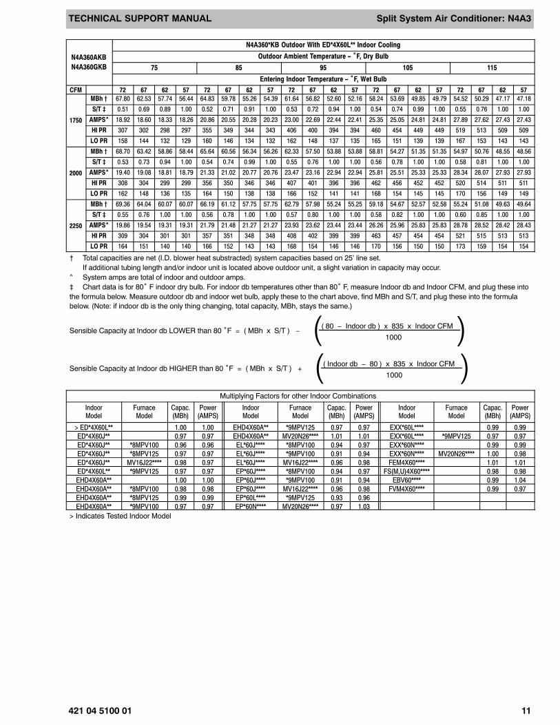
N4A360AKB
N4A360GKB
N4A360*KB Outdoor With ED*4X60L** Indoor Cooling
Outdoor Ambient Temperature − °F, Dry Bulb
75 85 95 105 115
Entering Indoor Temperature − °F, Wet Bulb
CFM 72 67 62 57 72 67 62 57 72 67 62 57 72 67 62 57 72 67 62 57
1750
MBh † 67.80 62.53 57.74 56.44 64.83 59.78 55.26 54.39 61.64 56.82 52.60 52.16 58.24 53.69 49.85 49.79 54.52 50.29 47.17 47.18
S/T ‡ 0.51 0.69 0.89 1.00 0.52 0.71 0.91 1.00 0.53 0.72 0.94 1.00 0.54 0.74 0.99 1.00 0.55 0.76 1.00 1.00
AMPS^ 18.92 18.60 18.33 18.26 20.86 20.55 20.28 20.23 23.00 22.69 22.44 22.41 25.35 25.05 24.81 24.81 27.89 27.62 27.43 27.43
HI PR 307 302 298 297 355 349 344 343 406 400 394 394 460 454 449 449 519 513 509 509
LO PR 158 144 132 129 160 146 134 132 162 148 137 135 165 151 139 139 167 153 143 143
2000
MBh † 68.70 63.42 58.86 58.44 65.64 60.56 56.34 56.26 62.33 57.50 53.88 53.88 58.81 54.27 51.35 51.35 54.97 50.76 48.55 48.56
S/T ‡ 0.53 0.73 0.94 1.00 0.54 0.74 0.99 1.00 0.55 0.76 1.00 1.00 0.56 0.78 1.00 1.00 0.58 0.81 1.00 1.00
AMPS^ 19.40 19.08 18.81 18.79 21.33 21.02 20.77 20.76 23.47 23.16 22.94 22.94 25.81 25.51 25.33 25.33 28.34 28.07 27.93 27.93
HI PR 308 304 299 299 356 350 346 346 407 401 396 396 462 456 452 452 520 514 511 511
LO PR 162 148 136 135 164 150 138 138 166 152 141 141 168 154 145 145 170 156 149 149
2250
MBh † 69.36 64.04 60.07 60.07 66.19 61.12 57.75 57.75 62.79 57.98 55.24 55.25 59.18 54.67 52.57 52.58 55.24 51.08 49.63 49.64
S/T ‡ 0.55 0.76 1.00 1.00 0.56 0.78 1.00 1.00 0.57 0.80 1.00 1.00 0.58 0.82 1.00 1.00 0.60 0.85 1.00 1.00
AMPS^ 19.86 19.54 19.31 19.31 21.79 21.48 21.27 21.27 23.93 23.62 23.44 23.44 26.26 25.96 25.83 25.83 28.78 28.52 28.42 28.43
HI PR 309 304 301 301 357 351 348 348 408 402 399 399 463 457 454 454 521 515 513 513
LO PR 164 151 140 140 166 152 143 143 168 154 146 146 170 156 150 150 173 159 154 154
† Total capacities are net (I.D. blower heat substracted) system capacities based on 25’ line set.If additional tubing length and/or indoor unit is located above outdoor unit, a slight variation in capacity may occur.
^ System amps are total of indoor and outdoor amps.‡ Chart data is for 80° F indoor dry bulb. For indoor db temperatures other than 80° F, measure Indoor db and Indoor CFM, and plug these intothe formula below. Measure outdoor db and indoor wet bulb, apply these to the chart above, find MBh and S/T, and plug these into the formulabelow. (Note: if indoor db is the only thing changing, total capacity, MBh, stays the same.)
Sensible Capacity at Indoor db LOWER than 80 °F = ( MBh x S/T ) −( 80 − Indoor db ) x 835 x Indoor CFM
1000( )Sensible Capacity at Indoor db HIGHER than 80 °F = ( MBh x S/T ) +
( Indoor db − 80 ) x 835 x Indoor CFM
1000( )Multiplying Factors for other Indoor Combinations
IndoorModel
FurnaceModel
Capac.(MBh)
Power(AMPS)
IndoorModel
FurnaceModel
Capac.(MBh)
Power(AMPS)
IndoorModel
FurnaceModel
Capac.(MBh)
Power(AMPS)
> ED*4X60L** 1.00 1.00 EHD4X60A** *9MPV125 0.97 0.97 EXX*60L**** 0.99 0.99
ED*4X60J** 0.97 0.97 EHD4X60A** MV20N26**** 1.01 1.01 EXX*60L**** *9MPV125 0.97 0.97
ED*4X60J** *8MPV100 0.96 0.96 EL*60J**** *8MPV100 0.94 0.97 EXX*60N**** 0.99 0.99
ED*4X60J** *8MPV125 0.97 0.97 EL*60J**** *9MPV100 0.91 0.94 EXX*60N**** MV20N26**** 1.00 0.98
ED*4X60J** MV16J22**** 0.98 0.97 EL*60J**** MV16J22**** 0.96 0.98 FEM4X60**** 1.01 1.01
ED*4X60L** *9MPV125 0.97 0.97 EP*60J**** *8MPV100 0.94 0.97 FS(M,U)4X60**** 0.98 0.98
EHD4X60A** 1.00 1.00 EP*60J**** *9MPV100 0.91 0.94 EBV60**** 0.99 1.04
EHD4X60A** *8MPV100 0.98 0.98 EP*60J**** MV16J22**** 0.96 0.98 FVM4X60**** 0.99 0.97
EHD4X60A** *8MPV125 0.99 0.99 EP*60L**** *9MPV125 0.93 0.96
EHD4X60A** *9MPV100 0.97 0.97 EP*60N**** MV20N26**** 0.97 1.03
> Indicates Tested Indoor Model

TECHNICAL SUPPORT MANUAL Split System Air Conditioner: N4A3
12 421 04 5100 01
Data for Condenser Only (Cooling)
Saturated SuctionTemperature °F
Condenser Entering Air Temperature °F
55 65 75 85 95 105 115 125
N4A318AKA, N4A318GKA
30
TCG 14.80 13.90 13.10 12.20 11.30 10.40 9.40 8.40
SDT 67.80 77.30 86.80 96.30 105.90 115.50 125.10 134.80
kW 0.80 0.92 1.06 1.21 1.37 1.54 1.73 1.93
35
TCG 16.30 15.40 14.40 13.50 12.50 11.60 10.60 9.50
SDT 68.80 78.20 87.70 97.20 106.70 116.20 125.80 135.40
kW 0.80 0.92 1.06 1.21 1.37 1.55 1.74 1.94
40
TCG 17.90 16.90 15.90 14.90 13.90 12.80 11.70 10.60
SDT 69.80 79.20 88.70 98.10 107.50 117.00 126.50 136.10
kW 0.80 0.92 1.05 1.20 1.37 1.55 1.74 1.95
45
TCG 19.50 18.50 17.40 16.30 15.20 14.10 13.00 11.70
SDT 70.90 80.30 89.70 99.10 108.40 117.80 127.20 136.70
kW 0.79 0.91 1.05 1.20 1.37 1.55 1.74 1.96
50
TCG 21.30 20.10 19.00 17.80 16.60 15.40 14.20 12.90
SDT 72.00 81.40 90.70 100.10 109.30 118.70 128.00 137.30
kW 0.79 0.91 1.05 1.20 1.36 1.55 1.74 1.96
55
TCG 23.00 21.80 20.60 19.30 18.00 16.80 15.50 14.10
SDT 73.20 82.50 91.80 101.10 110.30 119.50 128.80 138.00
kW 0.78 0.91 1.04 1.19 1.36 1.54 1.74 1.96
N4A324AKA, N4A324GKA
30
TCG 21.20 20.00 18.80 17.60 16.40 15.10 13.80 12.50
SDT 71.90 81.20 90.60 100.10 109.50 119.00 128.60 138.20
kW 1.04 1.19 1.37 1.56 1.77 2.01 2.26 2.53
35
TCG 23.30 22.10 20.80 19.50 18.20 16.80 15.40 13.90
SDT 73.20 82.50 91.80 101.10 110.50 119.90 129.40 139.00
kW 1.03 1.19 1.37 1.56 1.77 2.01 2.27 2.54
40
TCG 25.60 24.20 22.90 21.50 20.00 18.60 17.10 15.50
SDT 74.60 83.80 93.00 102.30 111.50 120.90 130.30 139.70
kW 1.03 1.19 1.37 1.56 1.78 2.01 2.27 2.55
45
TCG 28.00 26.50 25.00 23.50 22.00 20.40 18.80 17.10
SDT 76.00 85.10 94.30 103.50 112.60 121.90 131.20 140.50
kW 1.03 1.19 1.37 1.56 1.78 2.01 2.27 2.55
50
TCG 30.50 28.90 27.30 25.70 24.00 22.30 20.60 18.80
SDT 77.50 86.60 95.60 104.70 113.80 122.90 132.10 141.20
kW 1.03 1.19 1.37 1.56 1.77 2.01 2.27 2.55
55
TCG 33.00 31.30 29.60 27.80 26.10 24.30 22.40 20.40
SDT 79.00 88.00 97.00 106.00 114.90 124.00 133.00 142.00
kW 1.03 1.19 1.37 1.56 1.77 2.01 2.27 2.55
TCG = Gross Cooling Capacity (x 1000 BTU/hr)SDT = Saturated Temperature Leaving CompressorkW = Outdoor Unit Kilowatts

TECHNICAL SUPPORT MANUAL Split System Air Conditioner: N4A3
421 04 5100 01 13
Data for Condenser Only (Cooling)
Saturated SuctionTemperature °F
Condenser Entering Air Temperature °FSaturated SuctionTemperature °F 1251151059585756555
N4A330AKB, N4A330GKB
30
TCG 26.60 25.50 24.30 23.10 21.80 20.50 19.10 17.70
SDT 63.80 73.30 82.80 92.40 102.00 111.60 121.30 130.90
KW 1.32 1.50 1.71 1.94 2.20 2.48 2.78 3.11
35
TCG 29.30 28.10 26.80 25.50 24.20 22.80 21.30 19.80
SDT 64.80 74.20 83.60 93.20 102.70 112.30 121.90 131.50
KW 1.32 1.50 1.71 1.94 2.20 2.48 2.79 3.13
40
TCG 32.20 30.90 29.50 28.10 26.70 25.20 23.70 22.10
SDT 65.70 75.10 84.50 94.00 103.50 113.10 122.60 132.20
KW 1.32 1.50 1.71 1.94 2.20 2.49 2.80 3.14
45
TCG 35.30 33.90 32.50 30.90 29.40 27.80 26.20 24.50
SDT 66.80 76.10 85.50 94.90 104.40 113.90 123.40 132.90
KW 1.33 1.51 1.71 1.95 2.20 2.49 2.81 3.15
50
TCG 38.70 37.10 35.60 34.00 32.30 30.60 28.80 27.00
SDT 67.90 77.20 86.50 95.80 105.20 114.70 124.20 133.70
KW 1.33 1.51 1.72 1.95 2.21 2.50 2.81 3.16
55
TCG 42.20 40.60 38.90 37.20 35.40 33.60 31.70 29.80
SDT 69.20 78.30 87.50 96.80 106.20 115.60 125.10 134.50
KW 1.34 1.52 1.72 1.95 2.21 2.50 2.82 3.17
N4A336AKA, N4A336GKA
30
TCG 31.50 29.90 28.20 26.50 24.70 22.80 20.90 18.80
SDT 72.10 81.10 90.20 99.30 108.50 117.70 127.00 136.30
kW 1.62 1.82 2.05 2.31 2.59 2.90 3.23 3.58
35
TCG 34.70 32.90 31.10 29.20 27.30 25.30 23.20 21.00
SDT 73.70 82.50 91.50 100.50 109.60 118.70 127.90 137.10
kW 1.63 1.83 2.06 2.32 2.60 2.91 3.25 3.61
40
TCG 38.10 36.20 34.20 32.20 30.10 27.90 25.70 23.30
SDT 75.30 84.00 92.80 101.80 110.70 119.80 128.90 138.00
kW 1.64 1.84 2.07 2.33 2.62 2.93 3.27 3.63
45
TCG 41.70 39.60 37.50 35.30 33.10 30.70 28.30 25.70
SDT 77.00 85.60 94.30 103.10 112.00 121.00 129.90 138.90
kW 1.65 1.86 2.09 2.34 2.63 2.94 3.28 3.65
50
TCG 45.60 43.30 41.00 38.60 36.20 33.70 31.00 28.20
SDT 78.90 87.30 95.90 104.60 113.30 122.20 131.00 139.90
kW 1.67 1.87 2.10 2.36 2.64 2.96 3.30 3.67
55
TCG 49.60 47.10 44.60 42.00 39.40 36.70 33.80 30.80
SDT 80.80 89.10 97.50 106.10 114.70 123.40 132.10 140.80
kW 1.69 1.89 2.12 2.38 2.66 2.97 3.31 3.68
TCG = Gross Cooling Capacity (x 1000 BTU/hr)SDT = Saturated Temperature Leaving CompressorkW = Outdoor Unit Kilowatts

TECHNICAL SUPPORT MANUAL Split System Air Conditioner: N4A3
14 421 04 5100 01
Data for Condenser Only (Cooling)
Saturated SuctionTemperature °F
Condenser Entering Air Temperature °FSaturated SuctionTemperature °F 1251151059585756555
N4A342AKA, N4A342GKA
30
TCG 38.00 36.00 33.90 31.90 29.70 27.60 25.30 22.90
SDT 73.20 82.30 91.40 100.60 109.80 119.10 128.40 137.70
kW 1.95 2.20 2.48 2.80 3.14 3.53 3.95 4.41
35
TCG 41.90 39.70 37.40 35.10 32.80 30.50 28.00 25.50
SDT 74.80 83.70 92.80 101.90 111.00 120.20 129.40 138.60
kW 1.97 2.22 2.50 2.81 3.16 3.54 3.97 4.43
40
TCG 46.00 43.60 41.10 38.70 36.20 33.60 30.90 28.10
SDT 76.40 85.20 94.20 103.20 112.20 121.30 130.40 139.50
kW 1.98 2.23 2.52 2.83 3.18 3.56 3.98 4.44
45
TCG 50.30 47.70 45.10 42.40 39.60 36.80 33.90 30.90
SDT 78.10 86.90 95.70 104.60 113.50 122.50 131.40 140.40
kW 2.01 2.26 2.54 2.85 3.19 3.58 4.00 4.45
50
TCG 54.90 52.10 49.20 46.20 43.20 40.20 37.00 33.60
SDT 80.00 88.60 97.20 106.00 114.80 123.70 132.50 141.30
kW 2.03 2.28 2.56 2.87 3.21 3.60 4.01 4.47
55
TCG 59.70 56.60 53.40 50.20 46.90 43.50 40.10 36.40
SDT 81.90 90.30 98.90 107.50 116.20 124.90 133.60 142.20
kW 2.06 2.30 2.58 2.89 3.23 3.62 4.03 4.48
N4A348AKA, N4A348GKA
30
TCG 41.60 39.30 37.10 34.80 32.40 30.00 27.40 24.80
SDT 73.90 83.20 92.60 101.90 111.30 120.80 130.20 139.70
kW 2.24 2.54 2.87 3.24 3.64 4.08 4.56 5.08
35
TCG 45.80 43.40 40.90 38.50 35.90 33.30 30.60 27.70
SDT 75.40 84.70 93.90 103.20 112.50 121.90 131.30 140.70
kW 2.25 2.55 2.88 3.25 3.66 4.10 4.59 5.11
40
TCG 50.30 47.70 45.10 42.40 39.60 36.80 33.90 30.90
SDT 77.00 86.20 95.30 104.50 113.80 123.00 132.30 141.60
kW 2.26 2.56 2.89 3.26 3.67 4.12 4.61 5.14
45
TCG 55.10 52.30 49.50 46.60 43.60 40.60 37.50 34.20
SDT 78.60 87.70 96.80 105.90 115.00 124.20 133.40 142.60
kW 2.27 2.57 2.90 3.27 3.68 4.13 4.62 5.15
50
TCG 60.20 57.20 54.20 51.10 47.90 44.60 41.20 37.70
SDT 80.30 89.40 98.40 107.40 116.40 125.50 134.50 143.50
kW 2.28 2.59 2.92 3.29 3.70 4.15 4.64 5.17
55
TCG 65.70 62.50 59.20 55.80 52.40 48.90 45.20 41.30
SDT 82.10 91.10 100.00 108.90 117.80 126.80 135.70 144.50
kW 2.30 2.60 2.94 3.30 3.71 4.16 4.65 5.18
TCG = Gross Cooling Capacity (x 1000 BTU/hr)SDT = Saturated Temperature Leaving CompressorkW = Outdoor Unit Kilowatts

TECHNICAL SUPPORT MANUAL Split System Air Conditioner: N4A3
421 04 5100 01 15
Data for Condenser Only (Cooling)
Saturated SuctionTemperature °F
Condenser Entering Air Temperature °FSaturated SuctionTemperature °F 1251151059585756555
N4A360AKB, N4A360GKB
30
TCG 57.30 54.20 51.10 47.90 44.60 41.30 37.80 34.10
SDT 77.40 86.30 95.20 104.30 113.30 122.30 131.30 140.30
KW 2.71 3.05 3.43 3.86 4.33 4.84 5.40 5.99
35
TCG 62.90 59.50 56.10 52.60 49.00 45.40 41.60 37.50
SDT 79.30 88.00 96.90 105.80 114.70 123.70 132.60 141.40
KW 2.76 3.11 3.49 3.92 4.39 4.90 5.46 6.06
40
TCG 68.70 65.00 61.30 57.50 53.60 49.60 45.50 41.00
SDT 81.30 89.90 98.70 107.50 116.20 125.00 133.80 142.50
KW 2.83 3.17 3.56 3.98 4.45 4.96 5.52 6.12
45
TCG 74.80 70.80 66.70 62.60 58.30 54.00 49.40 44.60
SDT 83.40 91.90 100.50 109.20 117.80 126.50 135.10 143.60
KW 2.90 3.24 3.62 4.05 4.52 5.03 5.58 6.18
50
TCG 81.20 76.80 72.30 67.80 63.10 58.40 53.40 48.10
SDT 85.60 94.00 102.50 111.00 119.50 128.00 136.40 144.70
KW 2.97 3.32 3.70 4.12 4.59 5.10 5.65 6.24
55
TCG 87.80 83.00 78.10 73.10 68.10 62.90 57.50 51.70
SDT 88.00 96.20 104.40 112.80 121.10 129.50 137.70 145.80
KW 3.05 3.40 3.78 4.20 4.66 5.17 5.72 6.30
TCG = Gross Cooling Capacity (x 1000 BTU/hr)SDT = Saturated Temperature Leaving CompressorkW = Outdoor Unit Kilowatts

TECHNICAL SUPPORT MANUAL Split System Air Conditioner: N4A3
16 421 04 5100 01
B
L
A
2
32
3
C
F
D E
G
Nut, Acorn
GuardFan
MotorFan
Raceway
Fan
Top Cover
Grille, Inlet
Base, Pan
ServicePanel
ControlBox
ControlBoxCover
NOTE: This illustration is forreference only. Your unit maydiffer in appearance or may notinclude all components shown.Please refer to Parts List forexact parts listing.

TECHNICAL SUPPORT MANUAL Split System Air Conditioner: N4A3
421 04 5100 01 17
6
9
27
35
7
17
1
11
10
N
G
19
8
36
Condenser, CoilAssembly
Blanket ,Sound( When Used )
Compressor
Bolt, SHLDR (4)
Heater, CRKC( When Used )
Switch, LowPressure
Valve ServiceSuction
GrommetCompressor
SupportCoil
BasePan
Switch Temp.CC Heater(When Used)
Valve Service,Liquid
Switch, HighPressure
Plug, Compressor
,
,24Filter Drier
NOTE: This illustration is forreference only. Your unit maydiffer in appearance or may notinclude all components shown.Please refer to Parts List forexact parts listing.

TECHNICAL SUPPORT MANUAL Split System Air Conditioner: N4A3
18 421 04 5100 01
NOTE: This illustration is forreference only. Your unit maydiffer in appearance or may notinclude all components shown.
25
D
21
5
P
433
34
Box, Control
HarnessAssembly
Lug, Ground
Contactor
Strap,Capacitor
Capacitor
CTL, 2 SPD Fan
Module, CompressorDiagnostics
TECHNICAL SUPPORT MANUAL Split System Air Conditioner: N4A3
421 04 5100 01 19
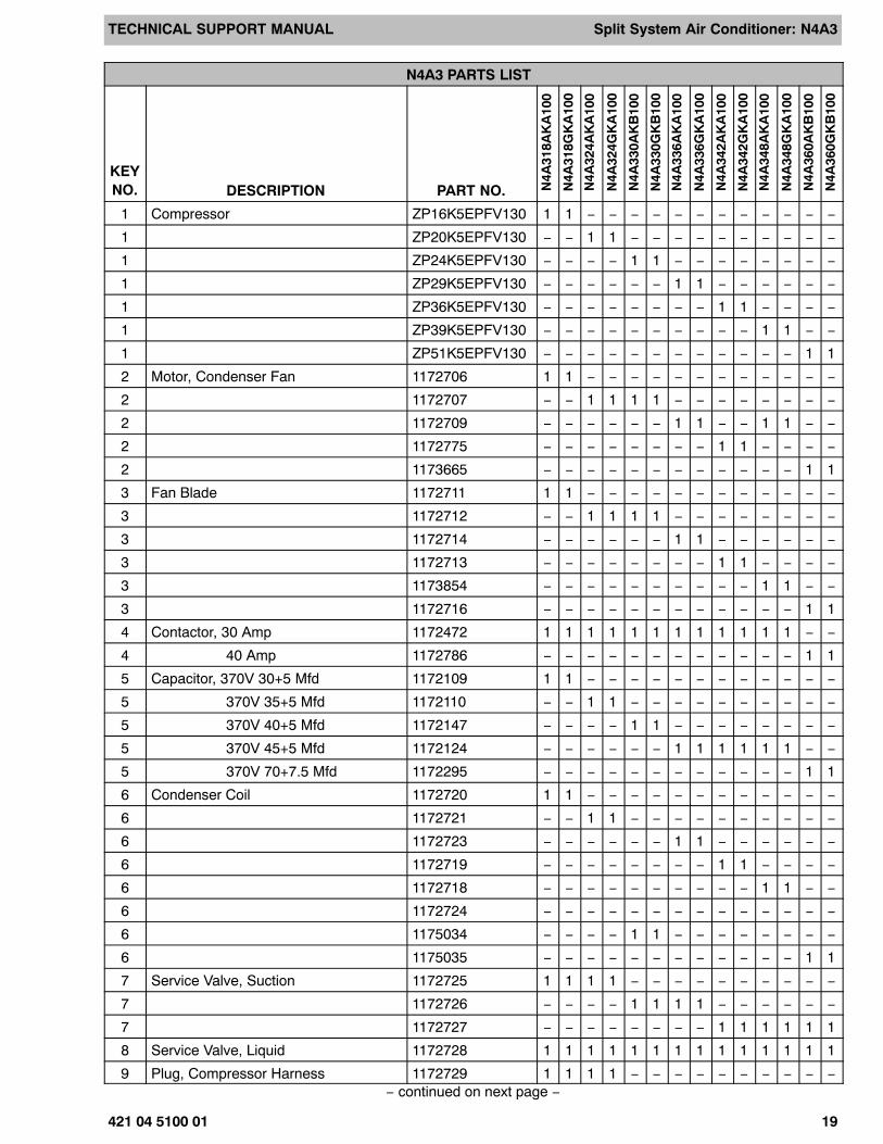
N4A3 PARTS LIST
KEYNO. DESCRIPTION PART NO. N
4A31
8AK
A10
0
N4A
318G
KA
100
N4A
324A
KA
100
N4A
324G
KA
100
N4A
330A
KB
100
N4A
330G
KB
100
N4A
336A
KA
100
N4A
336G
KA
100
N4A
342A
KA
100
N4A
342G
KA
100
N4A
348A
KA
100
N4A
348G
KA
100
N4A
360A
KB
100
N4A
360G
KB
100
1 Compressor ZP16K5EPFV130 1 1 − − − − − − − − − − − −
1 ZP20K5EPFV130 − − 1 1 − − − − − − − − − −
1 ZP24K5EPFV130 − − − − 1 1 − − − − − − − −
1 ZP29K5EPFV130 − − − − − − 1 1 − − − − − −
1 ZP36K5EPFV130 − − − − − − − − 1 1 − − − −
1 ZP39K5EPFV130 − − − − − − − − − − 1 1 − −
1 ZP51K5EPFV130 − − − − − − − − − − − − 1 1
2 Motor, Condenser Fan 1172706 1 1 − − − − − − − − − − − −
2 1172707 − − 1 1 1 1 − − − − − − − −
2 1172709 − − − − − − 1 1 − − 1 1 − −
2 1172775 − − − − − − − − 1 1 − − − −
2 1173665 − − − − − − − − − − − − 1 1
3 Fan Blade 1172711 1 1 − − − − − − − − − − − −
3 1172712 − − 1 1 1 1 − − − − − − − −
3 1172714 − − − − − − 1 1 − − − − − −
3 1172713 − − − − − − − − 1 1 − − − −
3 1173854 − − − − − − − − − − 1 1 − −
3 1172716 − − − − − − − − − − − − 1 1
4 Contactor, 30 Amp 1172472 1 1 1 1 1 1 1 1 1 1 1 1 − −
4 40 Amp 1172786 − − − − − − − − − − − − 1 1
5 Capacitor, 370V 30+5 Mfd 1172109 1 1 − − − − − − − − − − − −
5 370V 35+5 Mfd 1172110 − − 1 1 − − − − − − − − − −
5 370V 40+5 Mfd 1172147 − − − − 1 1 − − − − − − − −
5 370V 45+5 Mfd 1172124 − − − − − − 1 1 1 1 1 1 − −
5 370V 70+7.5 Mfd 1172295 − − − − − − − − − − − − 1 1
6 Condenser Coil 1172720 1 1 − − − − − − − − − − − −
6 1172721 − − 1 1 − − − − − − − − − −
6 1172723 − − − − − − 1 1 − − − − − −
6 1172719 − − − − − − − − 1 1 − − − −
6 1172718 − − − − − − − − − − 1 1 − −
6 1172724 − − − − − − − − − − − − − −
6 1175034 − − − − 1 1 − − − − − − − −
6 1175035 − − − − − − − − − − − − 1 1
7 Service Valve, Suction 1172725 1 1 1 1 − − − − − − − − − −
7 1172726 − − − − 1 1 1 1 − − − − − −
7 1172727 − − − − − − − − 1 1 1 1 1 1
8 Service Valve, Liquid 1172728 1 1 1 1 1 1 1 1 1 1 1 1 1 1
9 Plug, Compressor Harness 1172729 1 1 1 1 − − − − − − − − − −− continued on next page −

TECHNICAL SUPPORT MANUAL Split System Air Conditioner: N4A3
20 421 04 5100 01
N4A3 PARTS LIST (continued)
KEYNO. N
4A36
0GK
B10
0
N4A
360A
KB
100
N4A
348G
KA
100
N4A
348A
KA
100
N4A
342G
KA
100
N4A
342A
KA
100
N4A
336G
KA
100
N4A
336A
KA
100
N4A
330G
KB
100
N4A
330A
KB
100
N4A
324G
KA
100
N4A
324A
KA
100
N4A
318G
KA
100
N4A
318A
KA
100
PART NO.DESCRIPTION
9 1172730 − − − − 1 1 − − 1 1 − − − −
9 1172731 − − − − − − 1 1 − − 1 1 − −
9 1172732 − − − − − − − − − − − − 1 1
10 Grommet, Compressor 1171270 4 4 4 4 4 4 4 4 4 4 4 4 4 4
11 Bolt, Compressor Mounting 1173630 4 4 4 4 4 4 4 4 4 4 4 4 4 4
20 Distributor 1172021 − − − − − − − − − − − − 1 1
24 Drier 1174100 1 1 1 1 − − − − 1 1 1 1 − −
24 1174195 1 1 1 1 − − − − 1 1 1 1 1 1
24 1174727 − − − − 1 1 − − − − − − − −
24 1173955 − − − − − − 1 1 − − − − − −
32 Raceway 1173642 1 1 1 1 1 1 1 1 − − − − − −
32 1173651 − − − − − − − − 1 1 1 1 − −
32 1173664 − − − − − − − − − − − − 1 1
33 Lug, Ground 1172300 1 1 1 1 1 1 1 1 1 1 1 1 1 1
)( Harness, Wire Asy. 1172736 1 1 1 1 1 1 1 1 1 1 1 1 1 1
A Panel, Top 1174064 1 1 1 1 1 1 1 1 − − − − − −
A 1174075 − − − − − − − − 1 1 1 1 − −
A 1174079 − − − − − − − − − − − − 1 1
B Nut, Hex 1172740 4 4 4 4 4 4 4 4 4 4 4 4 4 4
C Grille, Inlet 1172741 1 − 1 − 1 − − − − − − − − −
C 1172747 − 1 − 1 − 1 − − − − − − − −
C 1172742 − − − − − − − − − − − − − −
C 1172748 − − − − − − − − − − − − −
C 1172743 − − − − − − 1 − − − − − − −
C 1172749 − − − − − − − 1 − − − − − −
C 1172744 − − − − − − − − 1 − − − − −
C 1172750 − − − − − − − − − 1 − − − −
C 1172745 − − − − − − − − − − 1 − − −
C 1172751 − − − − − − − − − − − 1 − −
C 1172746 − − − − − − − − − − − − 1 −
C 1172752 − − − − − − − − − − − − − 1
C 1173674 − − − − − − − − − − − − 1 −
C 1173675 − − − − − − − − − − − − − 1
D Box, Control 1172753 1 1 1 1 1 1 1 1 1 1 1 1 1 1
E Cover, Control Box 1174065 1 1 1 1 − − 1 1 1 1 1 1 − −
E 1175036 − − − − 1 1 − − − − − − − −
E 1175037 − − − − − − − − − − − − 1 1− continued on next page −

TECHNICAL SUPPORT MANUAL Split System Air Conditioner: N4A3
421 04 5100 01 21
N4A3 PARTS LIST (continued)
KEYNO. N
4A36
0GK
B10
0
N4A
360A
KB
100
N4A
348G
KA
100
N4A
348A
KA
100
N4A
342G
KA
100
N4A
342A
KA
100
N4A
336G
KA
100
N4A
336A
KA
100
N4A
330G
KB
100
N4A
330A
KB
100
N4A
324G
KA
100
N4A
324A
KA
100
N4A
318G
KA
100
N4A
318A
KA
100
PART NO.DESCRIPTION
F Panel, Service 1172755 1 1 1 1 1 1 − − − − − − − −
F 1174066 − − − − − − − − − − − − − −
F 1174080 − − − − − − 1 1 − − − − 1 1
F 1174071 − − − − − − − − 1 1 − − − −
F 1174777 − − − − − − − − − − 1 1 − −
G Pan, Base 1174067 1 1 1 1 1 1 1 1 − − − − − −
G 1174076 − − − − − − − − 1 1 1 1 − −
G 1174081 − − − − − − − − − − − − 1 1
L Guard, Fan 1172763 1 1 1 1 1 1 1 1 − − − − − −
L 1172764 − − − − − − − − 1 1 1 1 − −
L 1172765 − − − − − − − − − − − − 1 1
N Support, Coil 1173645 3 3 3 3 − − 3 3 5 5 5 5 − −
N 1174068 − − − − 3 3 − − − − − − 5 5
P Strap, Capacitor 1172734 1 1 1 1 1 1 1 1 1 1 1 1 − −
P 1172735 − − − − − − − − − − − − 1 1
)( Manual, Installation 42101510001 1 1 1 1 1 1 1 1 1 1 1 1 1 1
)( Manual, Owners 42102500000 1 1 1 1 1 1 1 1 1 1 1 1 1 1
)( Warranty 40106401000 1 1 1 1 1 1 1 1 1 1 1 1 1 1

TECHNICAL SUPPORT MANUAL Split System Air Conditioner: N4A3
22 421 04 5100 01
OUTDOOR UNIT MODEL NUMBER IDENTIFICATION GUIDE (single phase)Digit Position: 1 2 3 4 5, 6 7 8 9 10 11 12
Example Part Number: N 4 A 3 18 A K A 1 0 0H = Heil Mainline
N = Heil Entry BRANDING2 = R−224 = R−410A REFRIGERANTA = Air ConditionerH = Heat Pump TYPE3 = 13 SEER4 = 14 SEER NOMINAL EFFICIENCY18 = 18,000 BTUH = 1½ tons24 = 24,000 BTUH = 2 tons30 = 30,000 BTUH = 2½ tons36 = 36,000 BTUH = 3 tons42 = 42,000 BTUH = 3½ tons48 = 48,000 BTUH = 4 tons60 = 60,000 BTUH = 5 tons NOMINAL CAPACITYA = Standard GrilleG = Coil Guard GrilleC = Coastal FEATURES
K = 208/230−1−60 VOLTAGE
Sales Code
Engineering Revision
Extra Digit
Extra Digit
ACCESSORIES PART NUMBER IDENTIFICATION GUIDEDigit Position: 1 2 3 4 5 6, 7 8, 9 10, 11
Example Part Number: N A S A 0 0 1 01 C H
N = Non−Branded BRANDING
A = Accessory PRODUCT GROUP
S = Split System (AC & HP) KIT USAGEA = OriginalB = 2nd Generation MAJOR SERIES0 = Generic or Not Applicable
2 = R−22
4 = R−410A REFRIGERANTProduct Identifier Number
Package Quantity
Type of Kit(Example: CH = Crankcase Heater)
International Comfort Products, LLC
Lewisburg, Tennessee 37091