technical training emc monitor - praftec
TRANSCRIPT

PRAF MICROCOMPUTER TECHNOLOGIES LTD. P.O.B. 7209, Holon 5817101, Israel Tel.: +972-3-5031045, Fax: +972-3-5031046 http://www.praftec.com E-mail: [email protected]
POLAR MOHR is a registered trade mark of Polar-Mohr Maschinenvertriebsgesellschaft GmbH & Co. KG
DOC REF: (Reproduction)
POLAR-191110-EMC-MON-TECHNICAL-TRAINING Mon op gb 01 06.02.2006
PRAF Microcomputer Technologies Ltd. Confidential Company Property.POLAR-191110-EMC-MON-TECHNICAL-TRAINING Page 1 of 59 For internal use only.
Technical Training
EMC MONITOR
Optional Equipment

PRAF MICROCOMPUTER TECHNOLOGIES LTD. P.O.B. 7209, Holon 5817101, Israel Tel.: +972-3-5031045, Fax: +972-3-5031046 http://www.praftec.com E-mail: [email protected]
POLAR MOHR is a registered trade mark of Polar-Mohr Maschinenvertriebsgesellschaft GmbH & Co. KG
DOC REF: (Reproduction)
POLAR-191110-EMC-MON-TECHNICAL-TRAINING Mon op gb 01 06.02.2006
PRAF Microcomputer Technologies Ltd. Confidential Company Property.POLAR-191110-EMC-MON-TECHNICAL-TRAINING Page 2 of 59 For internal use only.
Table of contents: EMC – Monitor OPTIONAL EQUIPMENT
Special function (SFM) ……………………………………………………………………………………… 3 SFM Board ……..…………………………………………………………………………………………….. 4 Pin assignment of special functions………………………………………………………………………… 5 Arrangement of limit switches and valves on Autotrim …………………………………………………… 6 Optional Autotrim 80 ………………………………………………………………………………………… 7 Pneumatic Diagram of Autotrim …………………………………………………………………………… 8 Autotrim Wiring Diagram …………………………………………………………………………………… 9 Manual lowering of front table (up to V2.0) ………………………………………………………………… 10 Manual lowering of front table (as of V3.1) ………………………………………………………………… 11 Autotrim Parts List ……..……………………..……………………………………………………………… 12 Special Hydraulic System (SHM) …………………………………………………………………………… 14 SHM Board …………………………………………………………………………………………………… 15 Retractable side gauges on EM/EMC Monitor machines ………………………………………………… 16 New plug-in board “Special Hydraulic System” (SHM) …………………………………………………… 17 Backgauge Lock on EM/EMC – Monitor machines ……………………………………………………… 18 Circuit diagram of special hydraulic system Monitor ……………………………………………………… 19 Special hydraulic system parts list ………………………………………………………………………… 20 Swivel / tilting backgauge / Fixomat (DNF) (SER) ………………………………………………………… 22 DNF Board …………………………………………….……………………………………………………… 23 Basic mechanical adjustment of swivel - tilting backgauge ……………………………………………… 24 Adjustment of DNF Board for swivel backgauge ………………………………………………………… 25 Adjustment of DNF Board for tilting backgauge …………………………………………………………… 26 DNF Block Diagram …………………………………………………………………………………………. 27 DNF Parts List ………………………………………………………………………………………………… 28 Servo Control (optimized high-speed backgauge) ………………………………………………………… 29 Mains connection and block diagram of Servo Control …………………………………………………… 30 Connections at ESR ………………………………………………………………………………………… 32 SERVO Board ………………………………………………………………………………………………… 33 Setting instructions for Servo Board and Servo Amplifier ………………………………………………. 34 Service information for Servo Drive Unit …………………………………………………………………… 36 Automatic clamping pressure regulation (PDR) …………………………………………………………… 51 P1 Control unit for automatic clamping pressure regulation …………………………………………… 53 Functional principle of automatic clamping pressure regulation ………………………………………… 54 PDR setting instructions ……………………………………………………………………………………… 55 Program (V2.0) for automatic clamping pressure regulation …………………………………………… 56 PDR plug-in board …………………………………………………………………………………………… 57 P1 – Oil Cycle with proportional pressure regulating valve ……………………………………………… 58 PDR connecting plan ………………………………………………………………………………………… 59

PRAF MICROCOMPUTER TECHNOLOGIES LTD. P.O.B. 7209, Holon 5817101, Israel Tel.: +972-3-5031045, Fax: +972-3-5031046 http://www.praftec.com E-mail: [email protected]
POLAR MOHR is a registered trade mark of Polar-Mohr Maschinenvertriebsgesellschaft GmbH & Co. KG
DOC REF: (Reproduction)
POLAR-191110-EMC-MON-TECHNICAL-TRAINING Mon op gb 01 06.02.2006
PRAF Microcomputer Technologies Ltd. Confidential Company Property.POLAR-191110-EMC-MON-TECHNICAL-TRAINING Page 3 of 59 For internal use only.
Special function (SFM)
The special functions board (SFM) serves to control the Autotrim table. In connection with the CP1 board the program cycle provides an automatic activation of the solenoid valves for the pneumatic cylinder of the front table. On machines without Autotrim facility, this function must be turned off via switch S1 on the SFM board. The board carries also eight relays, which are energized for 0.5 seconds, each, when the external special functions 1-8 are executed. The potential free contacts of these relays allow to synchronize the peripheral equipments and the cutting sequence. The maximum tolerable load for the contacts is 10 Watts, 48V. Various inputs and outputs of the board allow for an adjustment of the control system to non-standard special versions. LED Color Meaning Ground state V20 Yellow AT - LS monitoring OFF V1 Red Autotrim table CLOSE ON V2 Red Autotrim table OPEN OFF V3 Red Cut OFF V4 Red Automatic backgauge ON OFF V5 Red Ext. special function No. 8 OFF V6 Red Ext. special function No. 7 OFF V7 Red Ext. special function No. 6 OFF V8 Red Ext. special function No. 5 OFF V9 Red Ext. special function No. 4 OFF V10 Red Ext. special function No. 3 OFF V11 Red Autotrim table LIFT No. 2 OFF V12 Red Autotrim table LOWER No. 1 OFF
The special functions 1-4 are carried out before the backgauge goes to the next position. The special functions 5-8 are performed when the size has been reached.

PRAF MICROCOMPUTER TECHNOLOGIES LTD. P.O.B. 7209, Holon 5817101, Israel Tel.: +972-3-5031045, Fax: +972-3-5031046 http://www.praftec.com E-mail: [email protected]
POLAR MOHR is a registered trade mark of Polar-Mohr Maschinenvertriebsgesellschaft GmbH & Co. KG
DOC REF: (Reproduction)
POLAR-191110-EMC-MON-TECHNICAL-TRAINING Mon op gb 01 06.02.2006
PRAF Microcomputer Technologies Ltd. Confidential Company Property.POLAR-191110-EMC-MON-TECHNICAL-TRAINING Page 4 of 59 For internal use only.
Plug-in board SFM

PRAF MICROCOMPUTER TECHNOLOGIES LTD. P.O.B. 7209, Holon 5817101, Israel Tel.: +972-3-5031045, Fax: +972-3-5031046 http://www.praftec.com E-mail: [email protected]
POLAR MOHR is a registered trade mark of Polar-Mohr Maschinenvertriebsgesellschaft GmbH & Co. KG
DOC REF: (Reproduction)
POLAR-191110-EMC-MON-TECHNICAL-TRAINING Mon op gb 01 06.02.2006
PRAF Microcomputer Technologies Ltd. Confidential Company Property.POLAR-191110-EMC-MON-TECHNICAL-TRAINING Page 5 of 59 For internal use only.
Pin assignment of special functions
* Autotrim: lower the front table ** Autotrim: lift the front table *** EXT. special functions 3-8 **** Spare

PRAF MICROCOMPUTER TECHNOLOGIES LTD. P.O.B. 7209, Holon 5817101, Israel Tel.: +972-3-5031045, Fax: +972-3-5031046 http://www.praftec.com E-mail: [email protected]
POLAR MOHR is a registered trade mark of Polar-Mohr Maschinenvertriebsgesellschaft GmbH & Co. KG
DOC REF: (Reproduction)
POLAR-191110-EMC-MON-TECHNICAL-TRAINING Mon op gb 01 06.02.2006
PRAF Microcomputer Technologies Ltd. Confidential Company Property.POLAR-191110-EMC-MON-TECHNICAL-TRAINING Page 6 of 59 For internal use only.
Arrangement of limit switches and valves on Autotrim
S363 limit switch for bypassing the Autotrim light barrier S364 limit switch Autotrim table closed S365 limit switch Autotrim table open
Y366 valve table closed Y367 valve table open Y389 valve sweeper ONY390 valve lower table

PRAF MICROCOMPUTER TECHNOLOGIES LTD. P.O.B. 7209, Holon 5817101, Israel Tel.: +972-3-5031045, Fax: +972-3-5031046 http://www.praftec.com E-mail: [email protected]
POLAR MOHR is a registered trade mark of Polar-Mohr Maschinenvertriebsgesellschaft GmbH & Co. KG
DOC REF: (Reproduction)
POLAR-191110-EMC-MON-TECHNICAL-TRAINING Mon op gb 01 06.02.2006
PRAF Microcomputer Technologies Ltd. Confidential Company Property.POLAR-191110-EMC-MON-TECHNICAL-TRAINING Page 7 of 59 For internal use only.
Optional Autotrim 80
This optional equipment allows to handle waste cuts up to a max. 80 mm. In order to make this function possible, the mechanical construction of the Autotrim table must be widely reworked. The extended travel of the table, the blowing air device for removing cutting waste from the knife bar (stripper flap is dropped) and the movable right-hand side gauge have caused modifications to the pneumatic system and electrical control. The following components of the electrical control unit are required for Autotrim 80:
1. New SFM board id. No. 020172 (replaces obsolete version 020171) 2. Suitable as of software versions V6.1-0, V5.3-0, V4.4-0
The new SFM plug-in board (020172) can be used for all Autotrim machines. For this purpose, the board has DIP switches, which allow the user to select between 25 mm and 80 mm for the waste cut. Switch position S2.5 = OFF - standard Autotrim (25 mm waste cut) Switch position S2.5 = ON - Autotrim 80 (80 mm waste cut) The hardware of the new SFM board has been changed in the following way: when the opening process of the table was interrupted, and the table is then closed, both solenoid valves are briefly activated in order to fill the cylinders. This enables the Autotrim table to be started slowly and without jerks. The time period for activating the solenoid valves can be set on the board. Any unassigned inputs which were only available on the board, have been supplied to a 9-pin D-SUB plug. The software modification of the CP1 board affects also the block program. Once Autotrim 80 is detected, any waste cut that may have been generated is set to 80 mm. New SFM, see IP1/93

PRAF MICROCOMPUTER TECHNOLOGIES LTD. P.O.B. 7209, Holon 5817101, Israel Tel.: +972-3-5031045, Fax: +972-3-5031046 http://www.praftec.com E-mail: [email protected]
POLAR MOHR is a registered trade mark of Polar-Mohr Maschinenvertriebsgesellschaft GmbH & Co. KG
DOC REF: (Reproduction)
POLAR-191110-EMC-MON-TECHNICAL-TRAINING Mon op gb 01 06.02.2006
PRAF Microcomputer Technologies Ltd. Confidential Company Property.POLAR-191110-EMC-MON-TECHNICAL-TRAINING Page 8 of 59 For internal use only.
Pneumatic diagram of Autotrim

PRAF MICROCOMPUTER TECHNOLOGIES LTD. P.O.B. 7209, Holon 5817101, Israel Tel.: +972-3-5031045, Fax: +972-3-5031046 http://www.praftec.com E-mail: [email protected]
POLAR MOHR is a registered trade mark of Polar-Mohr Maschinenvertriebsgesellschaft GmbH & Co. KG
DOC REF: (Reproduction)
POLAR-191110-EMC-MON-TECHNICAL-TRAINING Mon op gb 01 06.02.2006
PRAF Microcomputer Technologies Ltd. Confidential Company Property.POLAR-191110-EMC-MON-TECHNICAL-TRAINING Page 9 of 59 For internal use only.
Autotrim Wiring Diagram

PRAF MICROCOMPUTER TECHNOLOGIES LTD. P.O.B. 7209, Holon 5817101, Israel Tel.: +972-3-5031045, Fax: +972-3-5031046 http://www.praftec.com E-mail: [email protected]
POLAR MOHR is a registered trade mark of Polar-Mohr Maschinenvertriebsgesellschaft GmbH & Co. KG
DOC REF: (Reproduction)
POLAR-191110-EMC-MON-TECHNICAL-TRAINING Mon op gb 01 06.02.2006
PRAF Microcomputer Technologies Ltd. Confidential Company Property.POLAR-191110-EMC-MON-TECHNICAL-TRAINING Page 10 of 59 For internal use only.
Autotrim: Manual lowering of front table (up to V2.0)

PRAF MICROCOMPUTER TECHNOLOGIES LTD. P.O.B. 7209, Holon 5817101, Israel Tel.: +972-3-5031045, Fax: +972-3-5031046 http://www.praftec.com E-mail: [email protected]
POLAR MOHR is a registered trade mark of Polar-Mohr Maschinenvertriebsgesellschaft GmbH & Co. KG
DOC REF: (Reproduction)
POLAR-191110-EMC-MON-TECHNICAL-TRAINING Mon op gb 01 06.02.2006
PRAF Microcomputer Technologies Ltd. Confidential Company Property.POLAR-191110-EMC-MON-TECHNICAL-TRAINING Page 11 of 59 For internal use only.
Autotrim: Programmable lowering of front table (from V3.1)

PRAF MICROCOMPUTER TECHNOLOGIES LTD. P.O.B. 7209, Holon 5817101, Israel Tel.: +972-3-5031045, Fax: +972-3-5031046 http://www.praftec.com E-mail: [email protected]
POLAR MOHR is a registered trade mark of Polar-Mohr Maschinenvertriebsgesellschaft GmbH & Co. KG
DOC REF: (Reproduction)
POLAR-191110-EMC-MON-TECHNICAL-TRAINING Mon op gb 01 06.02.2006
PRAF Microcomputer Technologies Ltd. Confidential Company Property.POLAR-191110-EMC-MON-TECHNICAL-TRAINING Page 12 of 59 For internal use only.
Autotrim Parts List (up to V2.0)
Component Position Function M371 Table Compressor motor for suction and blown air N380 Frame Amplifier for light barrier, Autotrim Q386 Table Overload switch for compressor S361 Frame Button: Autotrim (open) in TR (pushbutton board – right) S362 Frame Button: Autotrim (close) in TR (pushbutton board – right) S363 Table Amplifier for light barrier, Autotrim S364 Table Limit switch Autotrim (close) S365 Table Limit switch Autotrim (open) S368 Table Changeover switch suction air – blown air S384 Tiltable table Tilt table limit switch “Left” S385 Tiltable table Tilt table limit switch “right” S386 Gearbox Control switch for sweeper S388 Table Button for sweeper “ON – OFF” SFM CU Plug-in board: Special function - Monitor SER Switching board Special electrical system carrying the relay unit V361 Frame LED table (open) in TR V383 Frame Flashing diode for light barrier Autotrim V381 Frame Transmitter for light barrier Autotrim V382 Frame Receiver for light barrier Autotrim Y94a Table Solenoid valve “air supply ON/OFF” Y366 Table Solenoid valve Autotrim (close) Y367 Table Solenoid valve Autotrim (open) Y370 Table Solenoid valve suction air Y389 Table Solenoid valve sweeper

PRAF MICROCOMPUTER TECHNOLOGIES LTD. P.O.B. 7209, Holon 5817101, Israel Tel.: +972-3-5031045, Fax: +972-3-5031046 http://www.praftec.com E-mail: [email protected]
POLAR MOHR is a registered trade mark of Polar-Mohr Maschinenvertriebsgesellschaft GmbH & Co. KG
DOC REF: (Reproduction)
POLAR-191110-EMC-MON-TECHNICAL-TRAINING Mon op gb 01 06.02.2006
PRAF Microcomputer Technologies Ltd. Confidential Company Property.POLAR-191110-EMC-MON-TECHNICAL-TRAINING Page 13 of 59 For internal use only.
Autotrim Parts List (from V3.1)
Component Position Function K1 TR Relay Lift the front table K2 TR Relay Lower the front table K3 TR Relay Change-over “blown air/suction air” M371 Table Compressor motor for blown air and suction air N380 Frame Amplifier for light barrier, Autotrim Q386 Table Overload switch for compressor S361 TR Button Autotrim “open” S362 TR Button Autotrim “close” S363 Table Amplifier for light barrier, Autotrim S364 Table Limit switch Autotrim (close) S365 Table Limit switch Autotrim (open) S384 Tiltable table Tilt table limit switch “left” S385 Tiltable table Tilt table limit switch “right” S386 Gearbox Control switch for sweeper “ON–OFF” S388 Table Button for sweeper “ON–OFF” S400 TR Button Autotrim Lift the front table S401 TR Button Autotrim Lower the front table SFM CU Plug-in board: Special function - Monitor SER Switching board Special electrical system carrying the relay unit TR Light barrier Pushbutton plate, right-hand V2 TR Flashing diode for light barrier Autotrim V3 TR LED Autotrim “open” V381 Frame Transmitter for light barrier Autotrim V382 Frame Receiver for light barrier Autotrim Y94a Table Solenoid valve “air supply ON/OFF” Y366 Table Solenoid valve Autotrim (close) Y367 Table Solenoid valve Autotrim (open) Y370 Table Solenoid valve Change-over „blown air - suction air“ Y389 Table Solenoid valve sweeper Y390 Table Solenoid valve Lower the front table

PRAF MICROCOMPUTER TECHNOLOGIES LTD. P.O.B. 7209, Holon 5817101, Israel Tel.: +972-3-5031045, Fax: +972-3-5031046 http://www.praftec.com E-mail: [email protected]
POLAR MOHR is a registered trade mark of Polar-Mohr Maschinenvertriebsgesellschaft GmbH & Co. KG
DOC REF: (Reproduction)
POLAR-191110-EMC-MON-TECHNICAL-TRAINING Mon op gb 01 06.02.2006
PRAF Microcomputer Technologies Ltd. Confidential Company Property.POLAR-191110-EMC-MON-TECHNICAL-TRAINING Page 14 of 59 For internal use only.
Special Hydraulic System (SHM)
The hydraulic valves for the special equipment for - Stack lifts
- Retractable side gauges - Backgauge lock
are activated from the special hydraulic system board. The logic for interlocking the output signals is located on this board. In order to activate the functions “retractable side gauge” and “backgauge lock”, the switches S1 and/or S2 must be turned to “1”. LED Color Meaning Ground state V8 Green +24V ON V9 Green +12V ON V10 Red Valve lift left-hand side Y160 OFF V11 Red Hy switch Y330 OFF V12 Red Valve lift right-hand side Y158 OFF V13 Red Valve VL left-hand side Y155a OFF V14 Red Valve VL right-hand side Y155b OFF V15 Red Valve - backgauge lock fixed Y331 OFF V16 Red Valve - backgauge lock clear Y391 OFF V17 Red Spare OFF V18 Red Spare OFF

PRAF MICROCOMPUTER TECHNOLOGIES LTD. P.O.B. 7209, Holon 5817101, Israel Tel.: +972-3-5031045, Fax: +972-3-5031046 http://www.praftec.com E-mail: [email protected]
POLAR MOHR is a registered trade mark of Polar-Mohr Maschinenvertriebsgesellschaft GmbH & Co. KG
DOC REF: (Reproduction)
POLAR-191110-EMC-MON-TECHNICAL-TRAINING Mon op gb 01 06.02.2006
PRAF Microcomputer Technologies Ltd. Confidential Company Property.POLAR-191110-EMC-MON-TECHNICAL-TRAINING Page 15 of 59 For internal use only.
Special Hydraulic System (SHM) Plug-in Board
VL = retractable side gauge

PRAF MICROCOMPUTER TECHNOLOGIES LTD. P.O.B. 7209, Holon 5817101, Israel Tel.: +972-3-5031045, Fax: +972-3-5031046 http://www.praftec.com E-mail: [email protected]
POLAR MOHR is a registered trade mark of Polar-Mohr Maschinenvertriebsgesellschaft GmbH & Co. KG
DOC REF: (Reproduction)
POLAR-191110-EMC-MON-TECHNICAL-TRAINING Mon op gb 01 06.02.2006
PRAF Microcomputer Technologies Ltd. Confidential Company Property.POLAR-191110-EMC-MON-TECHNICAL-TRAINING Page 16 of 59 For internal use only.
Retractable side gauges on EM/EMC Monitor machines
In the Monitor machine range, the 176 model was the first to introduce a new design of the hydraulically retractable side gauges. Both directions of motion (up/down) are now controlled hydraulically. The relevant limit positions are scanned via limit switches. On this version, the hydraulic pressure is turned off when the gauges are lowered. Besides the mechanical and hydraulic modifications this new model requires a new special hydraulics plug-in board. The new board SHM 020182 replaces the previous version with id. No. 020181. Before using this board with the older VL version, the switches and jumpers on the board need to be set correctly. There are three different variants: 1. Machines 115 to 155 (Programs V1.0 - V6.0) Version with unidirectional hydraulically controlled VL cylinder. Return motion (VL up) by spring power. The VL is retained in its bottom position by a constantly activated special hydraulic system. When employing the new SHM board (020182) the following setting needs to be made:
1. Switch S1 ON = VL available 2. Switch S2 ON = backgauge lock ON 3. Switch S3 ON = old VL version 4. Switch S4 ON = Cut optimization (must be turned on) 5. Jumper JP1 ON 6. Jumper JP2 ON 7. Jumper JP3 ON (Pin 1+2)
2. 176 Machines VL control in both directions through hydraulic system (twin cylinder).
1. Switch S1 ON = VL available 2. Switch S2 ON = backgauge lock ON (176 = OFF) 3. Switch S3 ON = old VL version 4. Switch S4 ON = Cut optimization (must be turned on) 5. Jumper JP1 OFF 6. Jumper JP2 OFF 7. Jumper JP3 ON (Pin 2+3)
3. Machines 115 to 155 (retrofit kit with program V 6.1) Version with unidirectional hydraulically controlled VL cylinder. Return motion (VL up) by spring power. By converting the hydraulic/electrical system, the VL can also be retained in its bottom position without any hydraulic pressure. This prevents excessive heating of the hydraulic system. The setting of switches and jumpers on the SHM board is the same as on the 176 MON machine.

PRAF MICROCOMPUTER TECHNOLOGIES LTD. P.O.B. 7209, Holon 5817101, Israel Tel.: +972-3-5031045, Fax: +972-3-5031046 http://www.praftec.com E-mail: [email protected]
POLAR MOHR is a registered trade mark of Polar-Mohr Maschinenvertriebsgesellschaft GmbH & Co. KG
DOC REF: (Reproduction)
POLAR-191110-EMC-MON-TECHNICAL-TRAINING Mon op gb 01 06.02.2006
PRAF Microcomputer Technologies Ltd. Confidential Company Property.POLAR-191110-EMC-MON-TECHNICAL-TRAINING Page 17 of 59 For internal use only.
Switches and jumper positions on the new SHM board
VL old with recovery spring
The function of the key vor > lower both VL <in the left-hand light barrier housing, can be preselected by removing or inserting the diode V7 on the new SHM board. If the diode is available, both VL are activated by pressing the key “lower both VL”. If there is no diode, only the right-hand VL will be activated. The operation of the left-hand VL remains unchanged.
see IP1/93
VL new with double Cylinder

PRAF MICROCOMPUTER TECHNOLOGIES LTD. P.O.B. 7209, Holon 5817101, Israel Tel.: +972-3-5031045, Fax: +972-3-5031046 http://www.praftec.com E-mail: [email protected]
POLAR MOHR is a registered trade mark of Polar-Mohr Maschinenvertriebsgesellschaft GmbH & Co. KG
DOC REF: (Reproduction)
POLAR-191110-EMC-MON-TECHNICAL-TRAINING Mon op gb 01 06.02.2006
PRAF Microcomputer Technologies Ltd. Confidential Company Property.POLAR-191110-EMC-MON-TECHNICAL-TRAINING Page 18 of 59 For internal use only.
Backgauge Lock on EM/EMC – Monitor machines
Description of functions:
The following solenoid valves are required for the backgauge lock function:
Y330 change-over valve (switch) Y331 needle valve tap (clamping ON) Y391 needle valve tap (clamping OFF)
On all the machines equipped with backgauge lock this function must be turned on with switch S2 on the SHM board. The functioning of individual valves is indicated by LED’s on the SHM board. (see SHM board). When the machine is turned on, no solenoid valve of the backgauge lock is activated, but through a spring storage element, which is integrated into the backgauge lock control unit, the backgauge lock remains activated even when the machine is switched off. With the backgauge at rest, the spring storage element also ensures that the pressure in the hydraulic circuit of the backgauge lock will be maintained even when the solenoid valves Y330 and Y331 are no longer energized. With a volume of approximately 3 cm³ the spring storage element is sufficient to compensate any arising pressure loss. By activating the motor brake of the backgauge drive motor, the solenoid valve Y391 is briefly turned on and provides a direct connection with the hydraulic tank. The oil contained in the backgauge lock control circuit flows off and the backgauge lock is relieved. When the backgauge stops, simultaneously with the shutoff of the motor brake the change-over valve Y330 and the needle valve tap Y331 are briefly turned on by the CP1 computer via the SHM board. In this way the oil circuit of the special hydraulic system is connected with pump P2 through the changeover valve, while the needle valve tap opens the line to the clamping cylinder at the sledge. The backgauge lock function is automatically carried out by CP1 provided that switch S2 on the SHM board is set to “1”. If the backgauge lock function is turned off by switch S2 on the SHM board, Y391 will be shortly activated to relieve the backgauge lock.

PRAF MICROCOMPUTER TECHNOLOGIES LTD. P.O.B. 7209, Holon 5817101, Israel Tel.: +972-3-5031045, Fax: +972-3-5031046 http://www.praftec.com E-mail: [email protected]
POLAR MOHR is a registered trade mark of Polar-Mohr Maschinenvertriebsgesellschaft GmbH & Co. KG
DOC REF: (Reproduction)
POLAR-191110-EMC-MON-TECHNICAL-TRAINING Mon op gb 01 06.02.2006
PRAF Microcomputer Technologies Ltd. Confidential Company Property.POLAR-191110-EMC-MON-TECHNICAL-TRAINING Page 19 of 59 For internal use only.
Circuit diagram of special hydraulic system

PRAF MICROCOMPUTER TECHNOLOGIES LTD. P.O.B. 7209, Holon 5817101, Israel Tel.: +972-3-5031045, Fax: +972-3-5031046 http://www.praftec.com E-mail: [email protected]
POLAR MOHR is a registered trade mark of Polar-Mohr Maschinenvertriebsgesellschaft GmbH & Co. KG
DOC REF: (Reproduction)
POLAR-191110-EMC-MON-TECHNICAL-TRAINING Mon op gb 01 06.02.2006
PRAF Microcomputer Technologies Ltd. Confidential Company Property.POLAR-191110-EMC-MON-TECHNICAL-TRAINING Page 20 of 59 For internal use only.
Parts list No. 1 - Special hydraulic system
Component Position Function CP1 CU Plug-in board: Central Processor CU Frame Control unit motherboard LG CU Air cup – distributor board PS CU Plug-in board: Power Supply +5V/12V/24V SHM CU Plug-in board: Special hydraulic system TL Frame Pushbutton board left-hand side TR Frame Pushbutton plate right-hand side S156a TL Key: Retractable side gauge, left-hand down S156b TL Key: Retractable side gauge, left and right-hand down S156c TL Key: Retractable side gauge, upper position S161a TR Key: Stack lift, right-hand side, up S161b TR Key: Stack lift, right-hand side, down S162a TL Key: Stack lift, left-hand side, up S162b TL Key: Stack lift, left-hand side, down S171 Lift Air cup: left-hand limit switch S173 Lift Air cup: right-hand limit switch SHM.K1 SHM Relay: solenoid valve – lift left-hand side up SHM.K2 SHM Relay: solenoid valve backgauge lock fixed SHM.K3 SHM Relay: solenoid valve - spare SHM.K4 SHM Relay: solenoid valve - retractable side gauge, right-hand SHM.K5 SHM Relay: Spare SHM.K6 SHM Relay: solenoid valve - retractable side gauge, left-hand SHM.K7 SHM Relay: Spare SHM.K8 SHM Relay: solenoid valve – lift right-hand side up SHM.K9 SHM Relay: Spare SHM.K10 SHM Relay: change-over valve ON SHM.K11 SHM Relay: solenoid valve backgauge lock relieved SHM.S1 SHM Changeover switch: Retractable gauge available / not available SHM.S2 SHM Changeover switch: backgauge lock activated / not activated SHM.V8 SHM Indication: Control voltage +12VDC SHM.V9 SHM Indication: Control voltage +24VDC SHM.P10 SHM Indication: solenoid valve – lift left-hand side ON SHM.P11 SHM Indication: change-over valve (switch) ON SHM.V12 SHM Indication: Lift, right-hand side ON SHM.V13 SHM Indication: Retractable side gauge, left-hand ON SHM.V14 SHM Indication: Retractable side gauge, right-hand ON SHM.V15 SHM Indication: backgauge lock fixed SHM.V16 SHM Indication: backgauge lock relieved SHM.V18 SHM Indication: Spare SHM.V19 SHM Indication: Spare SHM.V20 SHM Indication: Spare

PRAF MICROCOMPUTER TECHNOLOGIES LTD. P.O.B. 7209, Holon 5817101, Israel Tel.: +972-3-5031045, Fax: +972-3-5031046 http://www.praftec.com E-mail: [email protected]
POLAR MOHR is a registered trade mark of Polar-Mohr Maschinenvertriebsgesellschaft GmbH & Co. KG
DOC REF: (Reproduction)
POLAR-191110-EMC-MON-TECHNICAL-TRAINING Mon op gb 01 06.02.2006
PRAF Microcomputer Technologies Ltd. Confidential Company Property.POLAR-191110-EMC-MON-TECHNICAL-TRAINING Page 21 of 59 For internal use only.
Parts list No. 1 - Special hydraulic system (continued)
Component Position Function TL.V3 TL Indication: Retractable side gauge, left-hand lowered TL.V5 TL Indication: Retractable side gauge, both lowered Y155a Frame Solenoid valve: Retractable side gauge, left-hand down Y155b Frame Solenoid valve: Retractable side gauge, right-hand down Y158 Frame Solenoid valve: Stack lift, right-hand side, up Y160 Frame Solenoid valve: Stack lift, left-hand side, up Y170 Blower Solenoid valve: air for air cap left-hand side Y172 Blower Solenoid valve: air for air cap right-hand side Y330 Frame Change-over valve (switch) Y331 Frame Solenoid valve: backgauge lock fixed Y391 Frame Solenoid valve: backgauge lock relieved

PRAF MICROCOMPUTER TECHNOLOGIES LTD. P.O.B. 7209, Holon 5817101, Israel Tel.: +972-3-5031045, Fax: +972-3-5031046 http://www.praftec.com E-mail: [email protected]
POLAR MOHR is a registered trade mark of Polar-Mohr Maschinenvertriebsgesellschaft GmbH & Co. KG
DOC REF: (Reproduction)
POLAR-191110-EMC-MON-TECHNICAL-TRAINING Mon op gb 01 06.02.2006
PRAF Microcomputer Technologies Ltd. Confidential Company Property.POLAR-191110-EMC-MON-TECHNICAL-TRAINING Page 22 of 59 For internal use only.
Swivel / tilting backgauge / Fixomat (DNF) (SER)
The DNF Board controls the DC motors of the Fixomat front and side lay marks. The supply voltage of the motors is derived from the secondary voltage 0-15-30VAC of the control transformer. The three-phase motors for the swivel and tilting backgauge are activated through the relays K353-K354-K355-K356 on the SER board. Potentiometers acknowledge the current status of the backgauge setting. The analog voltages of the potentiometers are digitized on board DNF via an analog-digital converter and then signaled to the central processor (CP1). Depending on the machine equipment, the different functions need to be activated by the switches on the DNF board: S1 for tilting backgauge, S2 for swivel backgauge, S3 for Fixomat. LED Color Meaning Ground state V1 Yellow Tilting backgauge activated ON/OFF V2 Yellow Swivel backgauge 0 position S352 ON V3 Yellow Tilting backgauge 0 position S351 ON V4 Red ) V5 Red ) V6 Red indication for the position V7 Red Swivel / tilting backgauge V8 Red ) V9 Red ) V10 Yellow Fixomat side lay mark S341 resting position ON V11 Yellow Fixomat side lay mark activated S342 OFF V12 Yellow Fixomat front lay mark S343 resting position ON V13 Yellow Fixomat side lay mark activated S344 OFF V14 Red Fixomat side lay mark, swivel forward OFF V15 Red Fixomat swivel back the side lay mark OFF V16 Red Fixomat front lay mark swivel forward OFF V17 Red Fixomat swivel back the side lay mark OFF

PRAF MICROCOMPUTER TECHNOLOGIES LTD. P.O.B. 7209, Holon 5817101, Israel Tel.: +972-3-5031045, Fax: +972-3-5031046 http://www.praftec.com E-mail: [email protected]
POLAR MOHR is a registered trade mark of Polar-Mohr Maschinenvertriebsgesellschaft GmbH & Co. KG
DOC REF: (Reproduction)
POLAR-191110-EMC-MON-TECHNICAL-TRAINING Mon op gb 01 06.02.2006
PRAF Microcomputer Technologies Ltd. Confidential Company Property.POLAR-191110-EMC-MON-TECHNICAL-TRAINING Page 23 of 59 For internal use only.
DNF plug-in board

PRAF MICROCOMPUTER TECHNOLOGIES LTD. P.O.B. 7209, Holon 5817101, Israel Tel.: +972-3-5031045, Fax: +972-3-5031046 http://www.praftec.com E-mail: [email protected]
POLAR MOHR is a registered trade mark of Polar-Mohr Maschinenvertriebsgesellschaft GmbH & Co. KG
DOC REF: (Reproduction)
POLAR-191110-EMC-MON-TECHNICAL-TRAINING Mon op gb 01 06.02.2006
PRAF Microcomputer Technologies Ltd. Confidential Company Property.POLAR-191110-EMC-MON-TECHNICAL-TRAINING Page 24 of 59 For internal use only.
Basic mechanical adjustment
= swivel backgauge =
Basic mechanical adjustment = tilting backgauge =

PRAF MICROCOMPUTER TECHNOLOGIES LTD. P.O.B. 7209, Holon 5817101, Israel Tel.: +972-3-5031045, Fax: +972-3-5031046 http://www.praftec.com E-mail: [email protected]
POLAR MOHR is a registered trade mark of Polar-Mohr Maschinenvertriebsgesellschaft GmbH & Co. KG
DOC REF: (Reproduction)
POLAR-191110-EMC-MON-TECHNICAL-TRAINING Mon op gb 01 06.02.2006
PRAF Microcomputer Technologies Ltd. Confidential Company Property.POLAR-191110-EMC-MON-TECHNICAL-TRAINING Page 25 of 59 For internal use only.
Adjustment of board DNF for swivel and tilting backgauges
Swivel backgauge setting: Select swivel backgauge!
1. Move swivel backgauge mechanically to zero position (see page 24). 2. Adjust potentiometer RD in such a way that a voltage of 2.5V +/-0.05V can be measured between the measuring points MP1 and MP5. 3. Use potentiometer R41 to set the voltage between the measuring points MP1 and MP4 to 0V +/-2 mV. 4. Turn the center switching cam at the backgauge, until switch S352 is actuated. LED V2 is on. 5. Set the swivel backgauge to maximum mechanical displacement, using the controls – swivel backgauge right-hand side forward. (Before doing so, attach the dial gauge to the front edge of the rake.)
Swivel backgauge, right-hand (displacement at outside rake)
POLAR 115 1.3 mm POLAR 137 1.5 mm POLAR 155 1.7 mm
6. Turn the switching cam, until delimiting switch S348 is actuated. 7. Use potentiometer R39 (DNF) to set the following LED indications:
V4 OFF V5 OFF V6 ON V7 ON V8 OFF V9 OFF
This setting is equivalent with the value 20 in the indication with swivel backgauge right-hand side forward!
8. Set the swivel backgauge to maximum mechanical displacement, using the controls – swivel backgauge left-hand side forward. (Before doing so, attach the dial gauge to the front edge of the rake.)
Swivel backgauge left-hand side (displacement at outside rake)
POLAR 115 1.3 mm POLAR 137 1.5 mm POLAR 155 1.7 mm
9. Turn the switching cam, until delimiting switch S347 is actuated. After the setting is finished the monitor must display the following values for the final position:
swivel backgauge left + right-hand side = 20

PRAF MICROCOMPUTER TECHNOLOGIES LTD. P.O.B. 7209, Holon 5817101, Israel Tel.: +972-3-5031045, Fax: +972-3-5031046 http://www.praftec.com E-mail: [email protected]
POLAR MOHR is a registered trade mark of Polar-Mohr Maschinenvertriebsgesellschaft GmbH & Co. KG
DOC REF: (Reproduction)
POLAR-191110-EMC-MON-TECHNICAL-TRAINING Mon op gb 01 06.02.2006
PRAF Microcomputer Technologies Ltd. Confidential Company Property.POLAR-191110-EMC-MON-TECHNICAL-TRAINING Page 26 of 59 For internal use only.
Adjustment of board DNF for swivel and tilting backgauges
= Tilting backgauge setting = Select tilting backgauge!
1. Move tilting backgauge mechanically to zero position (see page 24). 2. Adjust potentiometer RN in such a way that a voltage of 2.9V +/-0.05V can be measured between the measuring points MP3 and MP5. 3. Use potentiometer R44 to set the voltage between the measuring points MP3 and MP4 to 0V +/-2mV. 4. Turn the center switching cam at the backgauge, until switch S351 is actuated. LED V3 is on. 5. Set the tilting backgauge to maximum mechanical displacement, using the controls - tilting backgauge backward. (Before doing so, attach the dial gauge to the front edge of the rake.)
Tilting backgauge “backward” (Displacement at upper edge of rake)
1.7 mm 1.7 mm 1.7 mm
6. Turn the switching cam, until delimiting switch S350 is actuated. 7. Use potentiometer R42 (DNF) to set the following LED indications:
V4 OFF V5 OFF V6 ON V7 ON V8 OFF V9 OFF
This setting is equivalent with the value 20 in the display only with tilting backgauge “backward”!
8. Set the tilting backgauge to maximum mechanical displacement, using the controls - tilting backgauge forward. (Before doing so, attach the dial gauge to the front edge of the rake.)
Tilting backgauge “forward” (Displacement at upper edge of rake)
0.5 mm 0.5 mm 0.5 mm
9. Turn the switching cam, until delimiting switch S349 is actuated. After the setting is finished the monitor must display the following values for the final position:
tilting backgauge backward = 20 tilting backgauge forward = 7

PRAF MICROCOMPUTER TECHNOLOGIES LTD. P.O.B. 7209, Holon 5817101, Israel Tel.: +972-3-5031045, Fax: +972-3-5031046 http://www.praftec.com E-mail: [email protected]
POLAR MOHR is a registered trade mark of Polar-Mohr Maschinenvertriebsgesellschaft GmbH & Co. KG
DOC REF: (Reproduction)
POLAR-191110-EMC-MON-TECHNICAL-TRAINING Mon op gb 01 06.02.2006
PRAF Microcomputer Technologies Ltd. Confidential Company Property.POLAR-191110-EMC-MON-TECHNICAL-TRAINING Page 27 of 59 For internal use only.
Detailed wiring diagram DNF

PRAF MICROCOMPUTER TECHNOLOGIES LTD. P.O.B. 7209, Holon 5817101, Israel Tel.: +972-3-5031045, Fax: +972-3-5031046 http://www.praftec.com E-mail: [email protected]
POLAR MOHR is a registered trade mark of Polar-Mohr Maschinenvertriebsgesellschaft GmbH & Co. KG
DOC REF: (Reproduction)
POLAR-191110-EMC-MON-TECHNICAL-TRAINING Mon op gb 01 06.02.2006
PRAF Microcomputer Technologies Ltd. Confidential Company Property.POLAR-191110-EMC-MON-TECHNICAL-TRAINING Page 28 of 59 For internal use only.
Parts List DNF
Component Position Function BIM Frame Control panel BT-DNF Frame Fixomat, swivel and tilting backgauge control unit CP1 CU Plug-in board: Central Processor CU Frame Control unit motherboard DNF Frame Swivel backgauge, tilting backgauge and Fixomat control unit KC Frame Keyboard Computer PM Frame Power supply unit SER Frame Special electrical system carrying the relay unit S341 Backgauge Limit switch: retracted, side lay mark S342 Backgauge Limit switch: extended, side lay mark M345 Backgauge Motor: Fixomat for side lay mark S343 Backgauge Limit switch: retracted, front lay mark S344 Backgauge Limit switch: extended, front lay mark M346 Backgauge Motor: Fixomat for front lay mark swivel backgauge S347 Backgauge Limit switch: backgauge, left-hand S352 Backgauge Limit switch: 0 position S348 Backgauge Limit switch: backgauge, right-hand RD Backgauge Potentiometer: Acknowledgement M357 Backgauge Motor for swivel backgauge K353 SER Relay: backgauge, left-hand K354 SER Relay: backgauge, right-hand Tilting backgauge S349 Backgauge Limit switch: Backgauge at front S351 Backgauge Limit switch: 0 position S350 Backgauge Limit switch: Backgauge at rear RN Backgauge Potentiometer: Acknowledgement M358 Backgauge Motor for tilting backgauge K355 SER Relay: Backgauge at front K356 SER Relay: Backgauge at rear V10 FIX Limit switch S341 actuated (end position side lay mark, rear) V11 FIX Limit switch S342 actuated (end position side lay mark, front) V12 FIX Limit switch S343 actuated (end position front lay mark, rear) V13 FIX Limit switch S344 actuated (end position front lay mark, front) V14 FIX Motor control M345 (retract side lay mark) V15 FIX Motor control M345 (extend side lay mark) V16 FIX Motor control M346 (retract front lay mark) V 17 FIX Motor control M 346 (extend front lay mark)

PRAF MICROCOMPUTER TECHNOLOGIES LTD. P.O.B. 7209, Holon 5817101, Israel Tel.: +972-3-5031045, Fax: +972-3-5031046 http://www.praftec.com E-mail: [email protected]
POLAR MOHR is a registered trade mark of Polar-Mohr Maschinenvertriebsgesellschaft GmbH & Co. KG
DOC REF: (Reproduction)
POLAR-191110-EMC-MON-TECHNICAL-TRAINING Mon op gb 01 06.02.2006
PRAF Microcomputer Technologies Ltd. Confidential Company Property.POLAR-191110-EMC-MON-TECHNICAL-TRAINING Page 29 of 59 For internal use only.
Servo Control
(optimized high-speed backgauge)
Mechanical system: Electrical system: Ball-bearing spindle Servo motor 120VDC (Bautz) Ball bushing Power Amplifier (ESR) Bearing housing (rear) Servo plug-in board (Servo) Spindle bearing block (front) CP1 Computer Board (V...S) Backgauge sledge (bigger bore hole) Rear limit switch S13a (O) * Motor pinion Front limit switch S7/S8 (O) * Spindle pinion Toothed belt Motor console
* In automatic operation the limit switches change over the backgauge speed to “slow“. (= a quarter of the maximum speed) On special versions (Transomat 3 BL, gripper transport system) the S121 switch is used instead of limit switch S13a. Description of Functions Mechanical system: The ball bearing spindle with ball bushing is set during the assembly in the factory. It requires no readjustment even after a longer operation time. The ball bearing spindle always has to be replaced completely, together with the ball bushing. Never turn the ball bushing off the spindle, because all the balls would drop out of the bushing and the bushing could not be used any longer. A mounting sleeve is necessary for installing the ball bushing onto the spindle and also for dismantling it. In dismantled condition, the spindle torque should be 1 Nm. In assembled condition a value of 2.5 Nm should not be exceeded. Electrical system: The ESR Servo power amplifier is mounted to the crosshead under the rear table. The mains connection is made from the machine with a 5-core cable via adapter plug No. 100. The supply voltage can be changed over in the power amplifier from 200-440V three-phase.

PRAF MICROCOMPUTER TECHNOLOGIES LTD. P.O.B. 7209, Holon 5817101, Israel Tel.: +972-3-5031045, Fax: +972-3-5031046 http://www.praftec.com E-mail: [email protected]
POLAR MOHR is a registered trade mark of Polar-Mohr Maschinenvertriebsgesellschaft GmbH & Co. KG
DOC REF: (Reproduction)
POLAR-191110-EMC-MON-TECHNICAL-TRAINING Mon op gb 01 06.02.2006
PRAF Microcomputer Technologies Ltd. Confidential Company Property.POLAR-191110-EMC-MON-TECHNICAL-TRAINING Page 30 of 59 For internal use only.
Power supply from control unit
The servo motor is connected with a shielded two-core cable from the power amplifier’s terminals 1 and 2, shielding terminal 3. The tachometer generator is also connected by a shielded 2-core cable at the power amplifier, terminals 4 and 5, shielding terminal 3. As on the machines without servo control, the motor brake is connected with a two-core cable, plug 104, at the MCM. Data transfer from the Servo board to the Servo power amplifier is performed with a four-core cable with 15-pin plug.
Servo Control block diagram

PRAF MICROCOMPUTER TECHNOLOGIES LTD. P.O.B. 7209, Holon 5817101, Israel Tel.: +972-3-5031045, Fax: +972-3-5031046 http://www.praftec.com E-mail: [email protected]
POLAR MOHR is a registered trade mark of Polar-Mohr Maschinenvertriebsgesellschaft GmbH & Co. KG
DOC REF: (Reproduction)
POLAR-191110-EMC-MON-TECHNICAL-TRAINING Mon op gb 01 06.02.2006
PRAF Microcomputer Technologies Ltd. Confidential Company Property.POLAR-191110-EMC-MON-TECHNICAL-TRAINING Page 31 of 59 For internal use only.
Explanations regarding the block diagram on page 30
(1*) = Enable: Signal „Motor ON“.
For backgauge movement, the enable signal is issued from CP1 via µP bus to PI. PI signals „brake enabled“ and the K1 relay on PI turns on the K1 relay on the Servo board. Zero signal is indicated on terminal 15 of the control unit and power amplifier is activated. Servo LED V9 = brake enabled / V1 = motor ON.
(2*) = Control signal:
Control voltage for motor speed control. Depending on the machine direction there is a voltage between 0 and +10VDC or 0 and -10VDC, 0V with “backgauge Stop”. The control signal is supplied from the CP1 via the µP bus and the „Servo“ board to the control unit (ESR, Terminal 11).
Through voltage control the motor speed is infinitely variable from Vo to Vmax. The motor brake is switched on when the CP1 has the signal Vo. The brake is meant to lock the motor at standstill. The Vmax speed (approximately 31 cm/Sec) is reached after approximately 13.5 cm, and in automatic mode, only. The regulation from Vmax to Vo requires also 13.5 cm. In the service display this value is indicated as a slow down travel. The Vmax speed is only obtained with distances of more than 27 cm. The max current of the control unit is set to 12A. If the current limit is set too low, the motor will not reach its full speed. At Vmax the current is about 5.5A. The motor speed is determined with a tachometer generator. When the speedometer fails, the backgauge will go to Vmax manually and without control. Poor carbon brushes will cause uneven operation! Drift velocity. This velocity is only determined in a reference run. Once the rear table limit switch (S13) has been reached, the backgauge stops its advance movement for approximately 2-3 Sec after about 15 cm. The power glide is measured and the backgauge moves forward to approximately 40 cm. The drift depends on the offset adjustment on the Servo board as well as the zero point in the ESR amplifier. Set the current limit. As of CP1 version V6.0 the error message “No pulses from measuring system” is issued when the backgauge is locked. From this program version, the auxiliary operation must be turned on before the current limit can be set. When the carbon brushes of the tachometer generator are worn or soiled, the motor will not run smoothly or it will approach the positions inaccurately.
Id. No. Brush Length Carbon Brushes for Motor 227361 (4 pcs.) 5 mm min Carbon Brushes for Tachogenerator 227362 (2 pcs.) 3 mm min
Control Signal Motor Tacho Vmax 9.5V 115V 40V Vmanual 4.5V 60V 20V Vslow 2.5V 30V 10V

PRAF MICROCOMPUTER TECHNOLOGIES LTD. P.O.B. 7209, Holon 5817101, Israel Tel.: +972-3-5031045, Fax: +972-3-5031046 http://www.praftec.com E-mail: [email protected]
POLAR MOHR is a registered trade mark of Polar-Mohr Maschinenvertriebsgesellschaft GmbH & Co. KG
DOC REF: (Reproduction)
POLAR-191110-EMC-MON-TECHNICAL-TRAINING Mon op gb 01 06.02.2006
PRAF Microcomputer Technologies Ltd. Confidential Company Property.POLAR-191110-EMC-MON-TECHNICAL-TRAINING Page 32 of 59 For internal use only.
The ESR has the following connections:
Terminal # Wire(s) Color Function
11 Orange +/-10V max, Value commands rotation speed, Polarity commands direction 13 Yellow -14V 14 Brown +14V 15 Red Enable (relay K1 on Servo Board) 20 Black (all) 0V Reference
The table limit switches S13a (S121) and S7 are connected to the Servo board by means of the 9-pin plug. The Servo power amplifier has three LED’s, which indicate different operational conditions. Operation LED# Color Operation/Alarm condition Normal Alarm Remarks LED1 Yellow Limit Switch opened, Enabling actuated OFF ON LED2 Red Overload OFF ON LED3 Green Normal Operation ON OFF All voltages available
Beneath the LED’s there are five trimming potentiometers POT# Function Clockwise trimming rotation remarks P4 Output Current Limit setting Current Limit is increased P3 Feedback adjustment Motor runs more smoothly P8 IxR Adaptive Load Compensation Stronger Compensation, used only w/Speed open loop P2 Zero point adjustment Motor standstill state (Clockwise - Counterclockwise) P1 Speed setting Speed is increased

PRAF MICROCOMPUTER TECHNOLOGIES LTD. P.O.B. 7209, Holon 5817101, Israel Tel.: +972-3-5031045, Fax: +972-3-5031046 http://www.praftec.com E-mail: [email protected]
POLAR MOHR is a registered trade mark of Polar-Mohr Maschinenvertriebsgesellschaft GmbH & Co. KG
DOC REF: (Reproduction)
POLAR-191110-EMC-MON-TECHNICAL-TRAINING Mon op gb 01 06.02.2006
PRAF Microcomputer Technologies Ltd. Confidential Company Property.POLAR-191110-EMC-MON-TECHNICAL-TRAINING Page 33 of 59 For internal use only.
Servo plug-in board

PRAF MICROCOMPUTER TECHNOLOGIES LTD. P.O.B. 7209, Holon 5817101, Israel Tel.: +972-3-5031045, Fax: +972-3-5031046 http://www.praftec.com E-mail: [email protected]
POLAR MOHR is a registered trade mark of Polar-Mohr Maschinenvertriebsgesellschaft GmbH & Co. KG
DOC REF: (Reproduction)
POLAR-191110-EMC-MON-TECHNICAL-TRAINING Mon op gb 01 06.02.2006
PRAF Microcomputer Technologies Ltd. Confidential Company Property.POLAR-191110-EMC-MON-TECHNICAL-TRAINING Page 34 of 59 For internal use only.
SERVO SETTING
!Move backgauge to center of table!
1. Zero balancing of Servo board in CUM module The Servo Board must be plugged onto an adapter. Make sure that the computer has preset a control voltage of 0V (automatic positioning must not be activated). Connect voltmeter to measuring points MP2 and J2 Pin 3. Use potentiometer P1 to set the voltage to 0V. Switch the machine off and remove the adapter board. 2. Zero balancing of Servo power amplifier ESR 2.a. Jumper J2 on the Servo board in such a way that the Pins 2 and 3 are linked. 2.b. Connect terminals 15 and 20 on the power amplifier with a jumper (enable). 2.c. By-pass the S18 switch of the manual precision adjustment at plug CUM 14, contacts 3 and 6, (Motor brake must be activated). Then, switch the machine on. 2.d. Adjust potentiometer P2 at the ESR (zero point adjustment), until servo motor is at a standstill (see “actual value” on the monitor or measure the speedometer voltage).
Switch machine off. 2.e. Plug jumper J2 on Servo board in such a way that the Pins 1 and 2 are linked. Remove bridges between terminals 15 and 20 as well as switch S18 at CUM14.6 and CUM14.3. 3. Setting the number of revolutions at the servo power amplifier (ESR) With the tachometer the number of revolutions is measured direct at the end of the spindle (second person necessary). The potentiometer P1 (speed) is adjusted in such a way that the spindle runs 1800 rpm in automatic operation, and 900 rpm in manual operation (use hand wheel). The motor speed must not exceed 2800 rpm (measured at the motor shaft). 4. Feedback setting procedure The feedback is set at P3 (feedback) in the following way: Turn the potentiometer P3 counterclockwise, until the servo motor runs audibly harsh. Then turn the potentiometer P3 slowly clockwise, until the servo motor runs smoothly over the entire speed range. Then check movement to position without display correction.

PRAF MICROCOMPUTER TECHNOLOGIES LTD. P.O.B. 7209, Holon 5817101, Israel Tel.: +972-3-5031045, Fax: +972-3-5031046 http://www.praftec.com E-mail: [email protected]
POLAR MOHR is a registered trade mark of Polar-Mohr Maschinenvertriebsgesellschaft GmbH & Co. KG
DOC REF: (Reproduction)
POLAR-191110-EMC-MON-TECHNICAL-TRAINING Mon op gb 01 06.02.2006
PRAF Microcomputer Technologies Ltd. Confidential Company Property.POLAR-191110-EMC-MON-TECHNICAL-TRAINING Page 35 of 59 For internal use only.
5. Setting the power limit The current setting at the servo power amplifier is carried out in the factory. It should only be readjusted when the P4 potentiometer (current setting) has been misadjusted or the red LED lights up because of an excessive load on the servomotor. The current can be set from 2-12 Amp. Lock the motor (best at the rear of the table). Switch measuring instrument into motor line (direct current up to 30 Amp). Set current at P4 to max 12 Amp. Note: From CP1 version V6.0 the auxiliary operation must be activated before the current limit can be set. Otherwise, when the backgauge is locked the error message “No pulses from measuring system” would be issued. After any new setting the machine must be initialized in a reference run, because the new machine parameters on the CP1 board must be saved as machine data! The servo board has six LED’s.
LED# Color Function indicating V1 Yellow Enabling of servo control; in operation “ON” V2 Red not assigned V3 Green not assigned V9 Yellow Motor brake active V10 Yellow Table limit switch S13a (S121) V11 Yellow Table limit switch S7
Technical Data:
Accuracy allowance 0.008 cm - 0.100 cm adjustable Slow down travel 13.000 cm approximately Brake afterrun 0-0.004 cm Drift (as of CP1 V6.0) cm/Sec (0, if possible)

PRAF MICROCOMPUTER TECHNOLOGIES LTD. P.O.B. 7209, Holon 5817101, Israel Tel.: +972-3-5031045, Fax: +972-3-5031046 http://www.praftec.com E-mail: [email protected]
POLAR MOHR is a registered trade mark of Polar-Mohr Maschinenvertriebsgesellschaft GmbH & Co. KG
DOC REF: (Reproduction)
POLAR-191110-EMC-MON-TECHNICAL-TRAINING Mon op gb 01 06.02.2006
PRAF Microcomputer Technologies Ltd. Confidential Company Property.POLAR-191110-EMC-MON-TECHNICAL-TRAINING Page 36 of 59 For internal use only.
SERVICE INFORMATION
Optimized high-speed backgauge (servo drive) 1. Servo Boards The following boards have been employed for servo machines by now Id. No. 023184 used up to program version V6.1/A-Z/O, inclusive Id. No. 029176 used from program version V6.2-0 Id. No. 029216 used only with model EMC-G (full graphics) Information regarding servo board id. No. 029176. This board helps to get a more distinct information from the error message “No pulses from measuring system“. There is a hint regarding a defective servo amplifier and backgauge motor. This distinction can only be made provided that program version as of V6.1 and the new set of cables (id. No. 029346 and 029348) are installed. On machines with 2-m table the cable set (id. No. 029346 and 029347) is indispensable. 2. CP1 computer board The following program statuses have been employed for servo machines so far: CP Board Id. No. CP1 V3.0S 020153 no longer available CP1 V3.1S 020157 no longer available CP1 V4.0S 023804 machines without PMS CP1 V4.1S 023611 keyboard computer id No. 020111 CP1 V4.2S 023612 CP1 V4.3S 023613 CP1 V4.4 023774 “S” identification is omitted, because program is also designed for normal
drive CP1 V5.0S 024340 machines with PMS CP1 V5.1S 024341 keyboard computer id No. 023831 CP1 V6.0S 024850 CP1 V6.1-0 a machines with PMS CP1 V6.1-0 b keyboard computer id No. 023832 CP1 V6.1-0 c CP1 V6.1-0 d CP1 V6.1-0 e CP1 V6.2-0 024841 “S” identification is omitted, because program is also designed for normal
drive replaces all programs from V6.1/A-Z/0
3. Cable harness: Servo Board / Servo Amplifier Old version, consisting of two cables with Id. No. 023173 and 023174 New version, consisting of two cables with Id. No. 029346 and 029348 New version of cables for 2-m table with Id. No. 029346 and 029347

PRAF MICROCOMPUTER TECHNOLOGIES LTD. P.O.B. 7209, Holon 5817101, Israel Tel.: +972-3-5031045, Fax: +972-3-5031046 http://www.praftec.com E-mail: [email protected]
POLAR MOHR is a registered trade mark of Polar-Mohr Maschinenvertriebsgesellschaft GmbH & Co. KG
DOC REF: (Reproduction)
POLAR-191110-EMC-MON-TECHNICAL-TRAINING Mon op gb 01 06.02.2006
PRAF Microcomputer Technologies Ltd. Confidential Company Property.POLAR-191110-EMC-MON-TECHNICAL-TRAINING Page 37 of 59 For internal use only.
4. Servo amplifier ESR The following devices have been used by now: ESR Device id. No. Primary Connection a. BN 6454.0715 227014 3x380V b. BN 6454.0890 227153 3x200V to 3x415V c. BN 6454.0950 227153 3x200V to 3x440V
The following PI wiring was selected for the above mentioned units: The wiring applies to the program versions V3.0S to V5.1S
1. R37 52K 2. C13 100nF d. BN 6454.1222 228925 3x200V to 3x440V
The following PI wiring was selected for the above mentioned units: The wiring applies to the program version V6.0S
1. R37 100K 2. C13 33nF e. BN 6454.1439 229229 3x200V to 3x440V
The following PI wiring was selected for the above mentioned unit: The wiring applies to program versions as of V6.1-0
1. R37 110K 2. C13 15nF
The BN 6454.1439 device is equipped with a DIP switch which makes it easy to make the PI adjustment when the device has to be replaced, (see section on PI wiring)
Some of the devices designated as assembly 1222 and 1439 are designed short-circuit proof. You can recognize this feature by a red-colored LED on the base plate of the amplifier. All those defective servo amplifiers sent-in for repair, which do not comply with the technical status of the BN 6454.1439 device will be modified correspondingly. This means that all replaced devices which have been given the new type number 1439 after their conversion, will provide the same configurations, which the new devices provide.

PRAF MICROCOMPUTER TECHNOLOGIES LTD. P.O.B. 7209, Holon 5817101, Israel Tel.: +972-3-5031045, Fax: +972-3-5031046 http://www.praftec.com E-mail: [email protected]
POLAR MOHR is a registered trade mark of Polar-Mohr Maschinenvertriebsgesellschaft GmbH & Co. KG
DOC REF: (Reproduction)
POLAR-191110-EMC-MON-TECHNICAL-TRAINING Mon op gb 01 06.02.2006
PRAF Microcomputer Technologies Ltd. Confidential Company Property.POLAR-191110-EMC-MON-TECHNICAL-TRAINING Page 38 of 59 For internal use only.
5. PI wiring at servo amplifier (PI = Proportional / Integral) The setting for the relevant program status is made with switches S1 to S6. For the current delivery status of the ESR device, please refer to the table.
S1 S2 S3 R37 S4 S5 S6 C13
0 0 0 0 0 0 1 0 0 249K 1 0 0 15nF 0 1 0 200K 0 1 0 33nF 1 1 0 110K 1 1 0 48nF 0 0 1 100K 0 0 1 100nF1 0 1 71K 1 0 1 115nF0 1 1 66K 0 1 1 133nF1 1 1 52K 1 1 1 148nF
LED1 Limit Switch is open LED2 Overload (Current Limit exceeded) LED3 Normal Operation POT4 Output Current Limit setting POT3 Feedback adjustment POT8 IxR Adaptive Load Compensation (open loop) POT2 Zero point adjustment (Motor Standstill State) POT1 Speed setting (Number of Revolutions)

PRAF MICROCOMPUTER TECHNOLOGIES LTD. P.O.B. 7209, Holon 5817101, Israel Tel.: +972-3-5031045, Fax: +972-3-5031046 http://www.praftec.com E-mail: [email protected]
POLAR MOHR is a registered trade mark of Polar-Mohr Maschinenvertriebsgesellschaft GmbH & Co. KG
DOC REF: (Reproduction)
POLAR-191110-EMC-MON-TECHNICAL-TRAINING Mon op gb 01 06.02.2006
PRAF Microcomputer Technologies Ltd. Confidential Company Property.POLAR-191110-EMC-MON-TECHNICAL-TRAINING Page 39 of 59 For internal use only.
Examples for replacing a servo amplifier: Machine 155 EMC - Monitor, S/No: 5821123, Program status V3.1S 1. If the complete servo amplifier of the mentioned machine was defective and has to be replaced, only the DIP switches for PI adjustment need to be fine-tuned. The switch package at amplifier 1439 becomes visible after the plug-in module at the ESR device has been removed (see drawing on page 39). Before putting the machine into service, the motor should also be inspected. (Please observe the maintenance of the motor). 2. Same condition as in item 1, but conversion to new software V6.1/A-Z/V6.2-0
a. New servo amplifier BN 6454.1439b. b. New servo board id. No. 029176c. c. New cable harness id. No. 029346 + 029348/029347d. d. New CP1 board id. No. 024841 (V6.2-0) e. New keyboard computer id No. 023832
These service parts are required for the complete conversion. After the parts have been assembled, the servo drive unit must be re-calibrated (see setting instructions for servo drive unit)
Servo amplifier with optional leakage protection equipment This optional equipment has been integrated into new devices from the model BN 6454.1222 onwards. It can be recognized from the red LED on the amplifier base plate. In normal operation the LED is off. When the LED lights up, the motor and supply line must be checked for accidental ground.
Plug-in module BN 37.1439
Output stages and controller board can be ordered under id. No. 229367 from our spare parts department. In case of a defect in an output stage, you always have to replace both modules. The assembly, id. No. 229367 is suitable for all the servo amplifiers delivered so far.

PRAF MICROCOMPUTER TECHNOLOGIES LTD. P.O.B. 7209, Holon 5817101, Israel Tel.: +972-3-5031045, Fax: +972-3-5031046 http://www.praftec.com E-mail: [email protected]
POLAR MOHR is a registered trade mark of Polar-Mohr Maschinenvertriebsgesellschaft GmbH & Co. KG
DOC REF: (Reproduction)
POLAR-191110-EMC-MON-TECHNICAL-TRAINING Mon op gb 01 06.02.2006
PRAF Microcomputer Technologies Ltd. Confidential Company Property.POLAR-191110-EMC-MON-TECHNICAL-TRAINING Page 40 of 59 For internal use only.
Block Diagram of Servo Drive Unit Forward movement of backgauge via hand wheel (button S10) 1. Input signal to Pl board (LED V23) 2. Information supplied via µP bus to CP1 3. CP1 controls PI board via µP bus a: Brake Y17 (LED V33) b: K1 on Pl (+24V via NO contact LED V9) 4. CP1 controls servo board via µP bus a: K1 on servo board (NC contact), =enabling of servo amplifier= b: Control signal for ESR device (approximately 4.8VDC)

PRAF MICROCOMPUTER TECHNOLOGIES LTD. P.O.B. 7209, Holon 5817101, Israel Tel.: +972-3-5031045, Fax: +972-3-5031046 http://www.praftec.com E-mail: [email protected]
POLAR MOHR is a registered trade mark of Polar-Mohr Maschinenvertriebsgesellschaft GmbH & Co. KG
DOC REF: (Reproduction)
POLAR-191110-EMC-MON-TECHNICAL-TRAINING Mon op gb 01 06.02.2006
PRAF Microcomputer Technologies Ltd. Confidential Company Property.POLAR-191110-EMC-MON-TECHNICAL-TRAINING Page 41 of 59 For internal use only.
Wiring diagram SERVO drive unit
Voltage Control Signal -10V..0..+10V Enabling 0V Feedback -14V..0..+14V Motor Voltage -120V..0..+120V Tacho Voltage -40V..0..+40V
Control signal: Control voltage for motor speed control. Depending on the direction of rotation and number of revolutions there is a voltage between 0 and +/-10VDC, respectively. The control signal is supplied from the CP1 through the µP bus via the “Servo” board to the control unit (ESR) terminal 11. Enable: Control signal “MOTOR ON”. For backgauge movement, the enable signal is issued from CP1 via µP bus to board PI. The PI board responds with the signal “brake Y17 electrically activated” and simultaneously turns on the K1 relay on the servo board with its relay K1. Zero signal is indicated on terminal 15 of the control unit and the power amplifier is activated. Servo LED: V9 ON = brake electrically activated / V1 ON = Motor on. Acknowledgement: Voltage level for CP1 Board for information about current motor speed. Depending on the number of revolutions and direction of rotation there is a voltage between 0 and +/-14V, respectively.

PRAF MICROCOMPUTER TECHNOLOGIES LTD. P.O.B. 7209, Holon 5817101, Israel Tel.: +972-3-5031045, Fax: +972-3-5031046 http://www.praftec.com E-mail: [email protected]
POLAR MOHR is a registered trade mark of Polar-Mohr Maschinenvertriebsgesellschaft GmbH & Co. KG
DOC REF: (Reproduction)
POLAR-191110-EMC-MON-TECHNICAL-TRAINING Mon op gb 01 06.02.2006
PRAF Microcomputer Technologies Ltd. Confidential Company Property.POLAR-191110-EMC-MON-TECHNICAL-TRAINING Page 42 of 59 For internal use only.
Problem solving for machines with servo drive
Zero point and drift cannot be adjusted correctly, or zero point or drift is not stable while machine is in operation. Optimal value for zero point or drift is the value >0.000< with the resulting brake afterrun, which is also >0.000< with optimal zero point or drift. Major variations between positive and negative values of drift and brake afterrun also indicate that there must be an error in the adjustment. Admissible tolerances for: Drift: +/-0.002 cm/Sec
Description of fault:
Brake afterrun: 0.000-0.004 cm maximum Mechanical check: Make sure that there is no mechanical stiffness throughout the backgauge travel. First, remove the toothed belt from the spindle drive unit. Then slowly move the backgauge over the entire travel, using a torque wrench. The max. admissible torque of 2.5 Nm must not be exceeded in this case. If the value is higher on some points, please check the spindle guides, spindle and backgauge support for damages. The permissible torque of the spindle alone (friction value spindle/nut) must not exceed 1 Nm. Moreover, after activation of the motor brake an unimpeded rotation of the motor must be possible. This can be ensured by supplying the brake coil directly with +24VDC. If you notice a partial mechanical stiffness, please re-adjust the brake or replace it. Inspection of the motor control system: As far as the servo control system is concerned, all the conversion steps should be taken to obtain the status BN 6454.1439. This includes modifying the servo board and the amplifier cable. The following measure should be performed: 1. At the servo amplifier, please remove the bridge between the two terminals No. 12 and No. 20. 2. The amplifier (ESR) has a jumper on the base plate, which must be removed. 3. Attach jumpers on the servo board. 4. Modify connection cable of servo amplifier.
(please observe the drawings on pages 47 and 48 when carrying out the conversion) If an additional error differentiation in the display shall be obtained, upgrade the program to version V6.1-0 or higher, and install the new cable harness which has two additional cores. The new servo board id. No. 029176 is also required.

PRAF MICROCOMPUTER TECHNOLOGIES LTD. P.O.B. 7209, Holon 5817101, Israel Tel.: +972-3-5031045, Fax: +972-3-5031046 http://www.praftec.com E-mail: [email protected]
POLAR MOHR is a registered trade mark of Polar-Mohr Maschinenvertriebsgesellschaft GmbH & Co. KG
DOC REF: (Reproduction)
POLAR-191110-EMC-MON-TECHNICAL-TRAINING Mon op gb 01 06.02.2006
PRAF Microcomputer Technologies Ltd. Confidential Company Property.POLAR-191110-EMC-MON-TECHNICAL-TRAINING Page 43 of 59 For internal use only.
Maintenance and repair of the servo motor with holding brake
The DC motor (made by Bautz) employed for driving the ball bearing spindle is composed of three assemblies: 1. DC Motor (carbon brushes id. No. 227361 (4 pcs.)) The maximum voltage allowed to be supplied to the motor is 120VDC. The motor is supplied from the ESR amplifier (terminals 1 & 2) via carbon brushes onto the collector. The max. adjusted voltage in this example is approximately 112VDC at a motor speed of approximately 2,800 rpm. Important! The new carbon brushes are 17 mm long, and must never be shorter than 5 mm. Besides, please make sure that the carbon brushes show an even contact pattern. Since the carbon brushes are abrading and this powdered carbon collects in the motor and at the collector, the motor must be sent-in to the manufacturer for maintenance work after the carbon brushes have been changed for the third time. The motor cannot be cleaned on site, because the relevant cleaning devices (such as ultrasonic cleaning) are not available. Furthermore, when the motor is at the manufacturer’s for maintenance purposes, the bearing will be replaced and the collector re-worked. If the motor is not serviced, the deposit of carbon dust may cause an accidental ground in the motor which results in malfunctions, or may even cause the servo amplifier to be damaged in individual cases. Since the applications of the cutting machines vary greatly it is not possible to indicate a definite period for the change of the carbon brushes. The motor should also be inspected with regard to accidental ground, before new brushes are installed or if there are temporary malfunctions of the servo drive. In that case disconnect the motor, check both lines for connection against the motor housing with an ohmmeter; the collector should also been turned for this purpose). 2. Tachogenerator (carbon brushes id. No. 227362 (2 pcs.)) The tachometer generator is connected with the motor shaft and generates a voltage during the motor run, which is supplied to the generator carbon brushes to the servo amplifier (terminals 4 & 5). This voltage governed by the speed serves to control and stabilize the motor speed. Important! The new carbon brushes are 9 mm long, and must never be shorter than 3 mm. Please observe the contact pattern of the brushes also in this case. The generated voltage with max. speed is approximately 38VDC and can be measured between terminals 4 & 5 of the servo amplifier. 3. Holding brake The servo control positions the backgauge precisely to the nominal position. Therefore the brake performs only a holding function and is consequently smaller than the brake on a machine of the same type, but with a normal drive system. The supply voltage is 24VDC, the brake air gap to be adjusted is 0.2 mm. Since April 1990 Polar uses the brake made by Mayer. This brake is identical with the previously used Lenze brake as far as the function is concerned, but the adjustment of the brake air gap is different. In the past, some motors showed broken locking pins, which caused the machines to break down. This is the reason why we have been gluing the hub of the brake rotor additionally with Loctite 290 on the motor shaft since one year ago. Now, should this particular type of locking pin (DIN 7344-2,5x16 / id. No. 203490) break on older motors, the damage can be eliminated on site by gluing the hub and inserting a new pin.

PRAF MICROCOMPUTER TECHNOLOGIES LTD. P.O.B. 7209, Holon 5817101, Israel Tel.: +972-3-5031045, Fax: +972-3-5031046 http://www.praftec.com E-mail: [email protected]
POLAR MOHR is a registered trade mark of Polar-Mohr Maschinenvertriebsgesellschaft GmbH & Co. KG
DOC REF: (Reproduction)
POLAR-191110-EMC-MON-TECHNICAL-TRAINING Mon op gb 01 06.02.2006
PRAF Microcomputer Technologies Ltd. Confidential Company Property.POLAR-191110-EMC-MON-TECHNICAL-TRAINING Page 44 of 59 For internal use only.
List of error messages for servo amplifier BN 6454.xxxx
for optimized high-speed backgauge Error: Motor turns in neither direction of rotation
Cause No. 1: Soldered fuse of surge limiter BN 1778.715 is open.
Indication: All LED in order, bimetal clip open.
Error cause: Mains transformer badly connected on the primary side? Excessive intermediate
circuit voltage, caused by feedback of excessive braking energy, for example by constant braking action of motor. Surge limiter defective?
Elimination: Re-establish soldered fuse connection by soldering. When doing so, make sure to retain the spring force of the bimetal.
Check: Under normal operational conditions the red LED of the surge limiter PC Board must be OFF. It may only light up briefly when the motor is reversed.
Cause No. 2: Short-to-ground responds.
Indication: Yellow LED (front panel) lights up; red LED on ground plate, or on older devices, red LED on additional board HL 6454.1439 on the first slot of the motherboard lights up.
Error cause: Accidental ground of one or both motor lines to the motor housing. Caused by parting of cable in the motor line and resulting accidental ground to the cable shield. By a worn-through motor cable. By dust of the brushes which caused arcing to the motor housing.
Elimination: In case of parting of cable install a new motor cable, check the motor, take measurement with an ohmmeter or high-voltage tester between motor housing and one motor cable. While doing so turn the motor shaft manually in order to detect a short over an entire rotation of the motor. In case of accidental ground, replace the motor. Important! For these measurements, the device must be turned off and the motor disconnected. In order to reset the stored display messages, the yellow and red LED on the device, turn the mains voltage off and re-connect it.
Check: Under normal operational conditions, the red LED on the motherboard or on supplementary board HL 6454.1439, as well as the yellow LED on the front panel must be OFF.

PRAF MICROCOMPUTER TECHNOLOGIES LTD. P.O.B. 7209, Holon 5817101, Israel Tel.: +972-3-5031045, Fax: +972-3-5031046 http://www.praftec.com E-mail: [email protected]
POLAR MOHR is a registered trade mark of Polar-Mohr Maschinenvertriebsgesellschaft GmbH & Co. KG
DOC REF: (Reproduction)
POLAR-191110-EMC-MON-TECHNICAL-TRAINING Mon op gb 01 06.02.2006
PRAF Microcomputer Technologies Ltd. Confidential Company Property.POLAR-191110-EMC-MON-TECHNICAL-TRAINING Page 45 of 59 For internal use only.
Cause No. 3: Connection error or defective supply line.
Indication: Yellow LED (ESR front side) lights up.
Error cause: - Enable input is open (terminal 15).
- Limit switch input is open (terminals 6 and 7). - Line break at these inputs. - Short-to-ground, simultaneously the red LED lights up.
Elimination: Measure the inputs (terminals 6, 7 and 15) to 0V (terminal 20) with voltmeter. The
inputs must be at 0V, in case of a malfunction the inputs go up to approximately +14V. Eliminate accidental ground in motor line.
Cause No. 4: Maladjustment or fault in motor circuit.
Indication: Red LED (ESR front side) lights up.
Error cause: - Current limit set too low. - Motor locked. - Motor connection lines short connected one against the other.
Elimination: Check motor lines for short circuit. Switch ammeter into motor line. Current limit was
too low and must be redefined. To do so, lock the motor. The pulse current will flow for some seconds. After that the devices switches back to constant current and the red LED lights up. In this condition the current is adjusted to the nominal current of the motor by means of the current limit potentiometer (front panel).
Check: The ammeter should be monitored for some time throughout the intended operation of the machine. In any case the mean current must be sufficiently below the adjusted current limit.
Cause No. 5: Interruption in motor circuit (broken).
Indication: All LED’s (ESR front side) are in order.
Error cause: - Motor line interrupted (broken). - Defective motor. - Defective output stage.
Elimination: - Measure nominal value input (terminals 11 and 12).
- Check carbon brushes of motor, use new ones, if necessary, or replace motor. - In case of defective output stage, replace entire plug-in section.
PRAF MICROCOMPUTER TECHNOLOGIES LTD. P.O.B. 7209, Holon 5817101, Israel Tel.: +972-3-5031045, Fax: +972-3-5031046 http://www.praftec.com E-mail: [email protected]
POLAR MOHR is a registered trade mark of Polar-Mohr Maschinenvertriebsgesellschaft GmbH & Co. KG
DOC REF: (Reproduction)
POLAR-191110-EMC-MON-TECHNICAL-TRAINING Mon op gb 01 06.02.2006
PRAF Microcomputer Technologies Ltd. Confidential Company Property.POLAR-191110-EMC-MON-TECHNICAL-TRAINING Page 46 of 59 For internal use only.
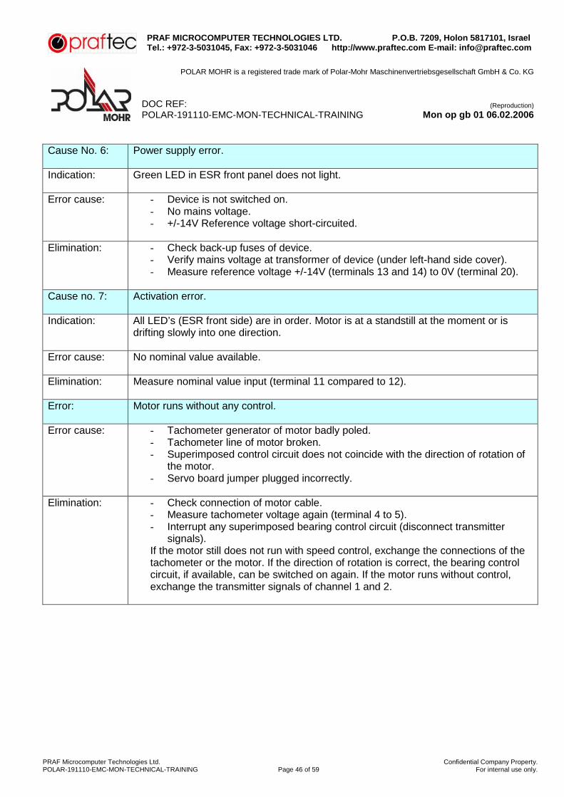
Cause No. 6: Power supply error.
Indication: Green LED in ESR front panel does not light.
Error cause: - Device is not switched on.
- No mains voltage. - +/-14V Reference voltage short-circuited.
Elimination: - Check back-up fuses of device.
- Verify mains voltage at transformer of device (under left-hand side cover). - Measure reference voltage +/-14V (terminals 13 and 14) to 0V (terminal 20).
Cause no. 7: Activation error.
Indication: All LED’s (ESR front side) are in order. Motor is at a standstill at the moment or is
drifting slowly into one direction.
Error cause: No nominal value available.
Elimination: Measure nominal value input (terminal 11 compared to 12).
Error: Motor runs without any control.
Error cause: - Tachometer generator of motor badly poled. - Tachometer line of motor broken. - Superimposed control circuit does not coincide with the direction of rotation of
the motor. - Servo board jumper plugged incorrectly.
Elimination: - Check connection of motor cable.
- Measure tachometer voltage again (terminal 4 to 5). - Interrupt any superimposed bearing control circuit (disconnect transmitter
signals). If the motor still does not run with speed control, exchange the connections of the tachometer or the motor. If the direction of rotation is correct, the bearing control circuit, if available, can be switched on again. If the motor runs without control, exchange the transmitter signals of channel 1 and 2.

PRAF MICROCOMPUTER TECHNOLOGIES LTD. P.O.B. 7209, Holon 5817101, Israel Tel.: +972-3-5031045, Fax: +972-3-5031046 http://www.praftec.com E-mail: [email protected]
POLAR MOHR is a registered trade mark of Polar-Mohr Maschinenvertriebsgesellschaft GmbH & Co. KG
DOC REF: (Reproduction)
POLAR-191110-EMC-MON-TECHNICAL-TRAINING Mon op gb 01 06.02.2006
PRAF Microcomputer Technologies Ltd. Confidential Company Property.POLAR-191110-EMC-MON-TECHNICAL-TRAINING Page 47 of 59 For internal use only.
Error: Motor is running rough and uneven.
Error cause: - Switches of reversible PI wiring are maladjusted or not closed.
- Potentiometer of feedback is badly adjusted (ESR front side).
Elimination: - Verify switch position of PI wiring and set according to preset values. - Adjust potentiometer of feedback. Turn counterclockwise, until the motor runs
perceptibly rough, then turn slowly clockwise until the motor runs smoothly over the complete speed range. Finally check brake afterrun and drift.
Error: Zero point cannot be set.
Error cause: - Zero loop in the wiring.
- There is still one nominal value from the control system.
Elimination:
- Check wiring. - Check activation of differential amplifier in the device (white colored wire on
motherboard) must be separated or removed). Verify nominal value at input (terminals 11 and 12).
Check: Disconnect nominal value from device and bridge terminals 11 and 12. Then adjust
the zero point. To do so, watch the motor shaft or measure the tachometer voltage.

PRAF MICROCOMPUTER TECHNOLOGIES LTD. P.O.B. 7209, Holon 5817101, Israel Tel.: +972-3-5031045, Fax: +972-3-5031046 http://www.praftec.com E-mail: [email protected]
POLAR MOHR is a registered trade mark of Polar-Mohr Maschinenvertriebsgesellschaft GmbH & Co. KG
DOC REF: (Reproduction)
POLAR-191110-EMC-MON-TECHNICAL-TRAINING Mon op gb 01 06.02.2006
PRAF Microcomputer Technologies Ltd. Confidential Company Property.POLAR-191110-EMC-MON-TECHNICAL-TRAINING Page 48 of 59 For internal use only.
Conversion of connecting cable at servo amplifier
Old Version
Connecting cable: 8 cores + shielding id. No. 023173 + 023174 All colored wires are twisted in pairs with a black wire, each. All black wires are combined on terminal 20.
New Version The orange wire, which is twisted in pairs with the orange wire is removed from terminal 20 and supplied to terminal 12. In order to make this quite sure, strip the insulation of the cable, if necessary.

PRAF MICROCOMPUTER TECHNOLOGIES LTD. P.O.B. 7209, Holon 5817101, Israel Tel.: +972-3-5031045, Fax: +972-3-5031046 http://www.praftec.com E-mail: [email protected]
POLAR MOHR is a registered trade mark of Polar-Mohr Maschinenvertriebsgesellschaft GmbH & Co. KG
DOC REF: (Reproduction)
POLAR-191110-EMC-MON-TECHNICAL-TRAINING Mon op gb 01 06.02.2006
PRAF Microcomputer Technologies Ltd. Confidential Company Property.POLAR-191110-EMC-MON-TECHNICAL-TRAINING Page 49 of 59 For internal use only.
Ramp adjustment of servo drive (as of V6.0)
Type of fault: With very smooth paper, error message “position not reached” and brake afterrun
exceeding 0,003 cm.
Possible cause: Mechanical stiffness of spindle or guiding mechanism.
Adjustment: By changing the values for starting (1) and braking stage (2) the ramp of the servo control system is modified. Home setting by factory; start and braking stage 4.
Inspection:
a. Switch off display correction in the Service image. Then select the display Adjust positioning. b. Enter some measurement in function 4 (positioning). c. Verify brake afterrun and drift values in the Service image. Drift value must not exceed +/-0.060 cm/Sec, optimal value: 0.000 cm/Sec. If the value exceeds the maximum, a new servo adjustment (see service documents) must be carried out. d. Check maximum speed in Service image. Nominal: 29.500 cm/Sec - approximately 1800 rpm at the spindle. e. Turn indication correction on.
Adjusting the ramp: Select starting (1) or braking stage (2) in the “Set positioning” image. Use the “+” or “-“ key on the control unit to change the value.
Test: a. Select positioning. b. Enter nominal sizes and confirm by pressing = key two times. c. Backgauge goes to nominal size with re-adjusted starting and braking stages. d. If there have been no errors during the inspection, you can immediately start from the data image. If there are problems, a new adjustment of the stages will be necessary. Press the “C” & “=” keys one after the other and select the new value.
Note: Drift is the value which is set at the servo adjustment at pot P2 (on ESR unit) and designated as zero point. Drift of 0.000 cm/Sec = zero point has been perfectly set, servo motor is at a standstill after the positioning process is terminated.
However, the indicated values of drifting and maximum speed only change after a reference run has been performed!

PRAF MICROCOMPUTER TECHNOLOGIES LTD. P.O.B. 7209, Holon 5817101, Israel Tel.: +972-3-5031045, Fax: +972-3-5031046 http://www.praftec.com E-mail: [email protected]
POLAR MOHR is a registered trade mark of Polar-Mohr Maschinenvertriebsgesellschaft GmbH & Co. KG
DOC REF: (Reproduction)
POLAR-191110-EMC-MON-TECHNICAL-TRAINING Mon op gb 01 06.02.2006
PRAF Microcomputer Technologies Ltd. Confidential Company Property.POLAR-191110-EMC-MON-TECHNICAL-TRAINING Page 50 of 59 For internal use only.
Parts List SERVO Motor
Component Position Function CP1 CU Plug-in board: Central Processor CU Frame Control Unit motherboard ESR Table SERVO control unit G1 SERVO Battery for clock (2.7VDC) J1 SERVO Bridge: Battery (G1) - Voltage ON J2 SERVO Bridge: Nominal value zero for SERVO amplifier K1 SERVO Relay for controller enabling M Table SERVO motor MCM Frame Backgauge motor control PI CU Positioning Interface S7 Table Switches: Changeover of advance speed “fast - slow” S13a Table Switches: Changeover of return stroke “fast – slow” T Motor Tachometer generator for SERVO motor SERVO CU Plug-in board: SERVO control Y17 Table Brake lifting solenoid for backgauge brake motor

PRAF MICROCOMPUTER TECHNOLOGIES LTD. P.O.B. 7209, Holon 5817101, Israel Tel.: +972-3-5031045, Fax: +972-3-5031046 http://www.praftec.com E-mail: [email protected]
POLAR MOHR is a registered trade mark of Polar-Mohr Maschinenvertriebsgesellschaft GmbH & Co. KG
DOC REF: (Reproduction)
POLAR-191110-EMC-MON-TECHNICAL-TRAINING Mon op gb 01 06.02.2006
PRAF Microcomputer Technologies Ltd. Confidential Company Property.POLAR-191110-EMC-MON-TECHNICAL-TRAINING Page 51 of 59 For internal use only.
Automatic clamping pressure regulation (PDR)
The control for automatic clamping pressure regulation is divided into two blocks.
A. Hydraulic control unit: Consisting of control block P1 with proportionally controlled pressure valve, one pressure sensor and two micro filters.
B. Electronic control unit: Consisting of:
1 PDR plug-in board 1 CUM module 8 Light sensors 8 Amplifiers for the light sensors 1 Stepping switch 0 – 10 for pressure presetting 1 Selector switch for sensors On/Off
Description of functions
The hydraulic P1 control unit has been newly conceived for automated clamping pressure regulation. It is composed of:
1. Proportional solenoid valve 2. Pop valve 3. Pressure sensor
The proportional solenoid valve is controlled to open or close at a varying degree by means of the current via the PDR board. The pop valve is set at the factory to a value of 150 bars to protect the pump. The valve seat in the proportional valve can be adjusted from the rear at the P1 control unit and has also been factory set to 25-28 bars. This setting cannot be made when the unit is installed. (From the front, a correction within a range of +/-3 bars can be made). Safety clamping pressure or clamping bar speed are adjusted in the usual way. (Please, refer to the sticker on the frame pillar containing the hydraulic system). The pressure sensor is required for the data acquisition for the electronic system. Its temperature compensation allows a max. pressure deviation of 1.5 bars in the range of 10-100°C. For automatic clamping pressure regulation the following connections are required at the CUM module and the PDR plug-in board.
Sensor amplifier 1-4, plug No. 825 CUM unit Sensor amplifier 5-8, plug No. 826 CUM unit Stepping switch clamping pressure selection and sensors ON/OFF. Both units are accommodated in the control unit.
Proportional Valve plug No. 701 CUM unit
plug No. 702 CUM unit
Pressure sensor control block hydraulic system Diode plug 6 - pin. PDR board

PRAF MICROCOMPUTER TECHNOLOGIES LTD. P.O.B. 7209, Holon 5817101, Israel Tel.: +972-3-5031045, Fax: +972-3-5031046 http://www.praftec.com E-mail: [email protected]
POLAR MOHR is a registered trade mark of Polar-Mohr Maschinenvertriebsgesellschaft GmbH & Co. KG
DOC REF: (Reproduction)
POLAR-191110-EMC-MON-TECHNICAL-TRAINING Mon op gb 01 06.02.2006
PRAF Microcomputer Technologies Ltd. Confidential Company Property.POLAR-191110-EMC-MON-TECHNICAL-TRAINING Page 52 of 59 For internal use only.
The clamping pressure selector switch is used for selecting the desired clamping pressure. If the switch for the sensors is turned off, the clamping pressure regulation works manually, i.e. the clamping pressure is adjusted according to the position of the preselection switch. Clamping pressure selector switch set to 10:
POLAR 115/137 = 4500kP (1 bar = 100 kP) POLAR 155 = 5500kP (1 bar = 100 kP) POLAR 176 = 6000kP (1 bar = 100 kP) (the unclear conversion from bar to kP)

PRAF MICROCOMPUTER TECHNOLOGIES LTD. P.O.B. 7209, Holon 5817101, Israel Tel.: +972-3-5031045, Fax: +972-3-5031046 http://www.praftec.com E-mail: [email protected]
POLAR MOHR is a registered trade mark of Polar-Mohr Maschinenvertriebsgesellschaft GmbH & Co. KG
DOC REF: (Reproduction)
POLAR-191110-EMC-MON-TECHNICAL-TRAINING Mon op gb 01 06.02.2006
PRAF Microcomputer Technologies Ltd. Confidential Company Property.POLAR-191110-EMC-MON-TECHNICAL-TRAINING Page 53 of 59 For internal use only.
P1 Control unit for automatic clamping pressure regulation

PRAF MICROCOMPUTER TECHNOLOGIES LTD. P.O.B. 7209, Holon 5817101, Israel Tel.: +972-3-5031045, Fax: +972-3-5031046 http://www.praftec.com E-mail: [email protected]
POLAR MOHR is a registered trade mark of Polar-Mohr Maschinenvertriebsgesellschaft GmbH & Co. KG
DOC REF: (Reproduction)
POLAR-191110-EMC-MON-TECHNICAL-TRAINING Mon op gb 01 06.02.2006
PRAF Microcomputer Technologies Ltd. Confidential Company Property.POLAR-191110-EMC-MON-TECHNICAL-TRAINING Page 54 of 59 For internal use only.
Functional principle of automatic clamping pressure regulation
When the switch for the sensors is turned on, the clamping pressure regulation works automatically, i.e. the clamping pressure is regulated according to the number of sensors covered. Regardless of the material alignment on the right or left-hand side in the machine: the more sensors are covered by material to be cut, the higher will the clamping pressure be. The control unit has an internal table, which differs for machine types 92 to 176. These tables include all the pressure values (stepping switch 0-10), which are combined with all the sensor conditions possible and the relevant current values for the proportional solenoid valve. This special recording of all the values (teach-in program) is made at the factory for every single type of machine, and will be retained even when the control system is turned off. When the PDR board or the hydraulic block P1 is replaced, the setting must be made according to the setting instructions, items A and B. The 8 sensors integrated in the machine table supply one signal, each, to the control unit via 8 amplifiers (1-4 on the right, 5-8 on the left side). At the factory the sensors are adjusted for dark paper. This can be seen from the red LED’s located at the individual amplifiers. When the sensor is covered, the LED at the relevant amplifier (24VDC) lights up. If no sensor is covered, all the LED’s are OFF (0V). If a readjustment is necessary, because an amplifier or fiber optic cable has been replaced or when extremely dark cutting material has been used, the sensitivity can be modified at the amplifier potentiometer (amplifiers are installed under the machine table) beneath the red LED, with the machine switched on. The sensitivity must not be increased so far that the amplifiers will be turned on by reflexions at the pressure clamp or at the lower side of the false clamp plate when the clamp is in its upper resting position. Cover the sensor with cutting material. Turn the potentiometer clockwise, until the red LED lights up. Take away the cutting material. The LED must go out. If not, repeat this procedure. When replacing a fiber optic cable, make sure that the cable will not be bent. It must be laid with a radius of at least three times the thickness of the cable. A cable is perfectly laid, when all the glass fibers on the amplifier side (unscrew cables from the amplifier) are light when the sensor is not covered. The fiber optic cable is screwed into the sensor bush with threaded sleeve ½ - ¾ turn to the cover plate. Then lock slightly. When mounting the table into the frame, please proceed with utmost care to prevent any damages to the light fiber cables under the table.

PRAF MICROCOMPUTER TECHNOLOGIES LTD. P.O.B. 7209, Holon 5817101, Israel Tel.: +972-3-5031045, Fax: +972-3-5031046 http://www.praftec.com E-mail: [email protected]
POLAR MOHR is a registered trade mark of Polar-Mohr Maschinenvertriebsgesellschaft GmbH & Co. KG
DOC REF: (Reproduction)
POLAR-191110-EMC-MON-TECHNICAL-TRAINING Mon op gb 01 06.02.2006
PRAF Microcomputer Technologies Ltd. Confidential Company Property.POLAR-191110-EMC-MON-TECHNICAL-TRAINING Page 55 of 59 For internal use only.
Instructions for setting the PDR board
Switch machine off. Wait, until main motor is at a standstill. Connect pressure sensor for pressure gauge to the test tap at the P1 control unit. Switch the machine on. A. Zero calibration (= circulation pressure) press RESET button
1. Set mode selector (MOD) on the PDR plug-in board to “2”. 2. Use the “offset” potentiometer to set the mode indication in such a way that the ten’s decade is
“0” and the unit decade jumps from “0” to “1” see illustration, PDR board). B. Adjustment amplification max. pressure V = max / P = max.
1. Leave mode selector on the PDR plug-in board at “2”. 2. Select special function “clamping without cutting” (D). 3. Press both cut buttons and set max. pressure with potentiometer P max.
POLAR 115, 137: 106 bar = 4500 daN (45000 N, decanewton = 10xN) POLAR 155: 130 bar = 5500 daN (55000 N, decanewton = 10xN) POLAR 176: 138 bar = 6000 daN (60000 N, decanewton = 10xN) (the unclear conversion from bar to daN)
4. Press both cut buttons again, and use potentiometer Vmax to set the on-indicator pilot light on
the ten’s decade to “F” and the unit decade to a value between “E” and “F” (junction). Repeat procedures A and B. Set operating mode switch (MOD) to position „0“.
C. Activate teach-in program
1. Set operating mode switch to position “1”. 2. Input cutting program, for example
100,000 cm + D (Special function “clamping without cutting”) ET 0.50 cm + D (Special function “clamping without cutting”) Adjust maximum retarding of cutting cycle with „clamping time“ rotary switch. Turn automatic knife on and trigger a cut.
3. Now all the table values (pressure values), from the minimum to the maximum pressure, stage 0 to stage 10 are now learned one by one. The displays on the PDR board show the following values:
Unit decade = clamping pressure stages 0-A (0-10) Ten’s decade = number of active sensors (0-8)
The training process is finished when the unit decade of 0-A and the ten’s decade of 0-8 have been run through. Once the teach-in program is terminated, set the operating switch to “0” position. The operating program is activated and the display of the PDR board shows the number of activated sensors and the preselected clamping pressure stage.

PRAF MICROCOMPUTER TECHNOLOGIES LTD. P.O.B. 7209, Holon 5817101, Israel Tel.: +972-3-5031045, Fax: +972-3-5031046 http://www.praftec.com E-mail: [email protected]
POLAR MOHR is a registered trade mark of Polar-Mohr Maschinenvertriebsgesellschaft GmbH & Co. KG
DOC REF: (Reproduction)
POLAR-191110-EMC-MON-TECHNICAL-TRAINING Mon op gb 01 06.02.2006
PRAF Microcomputer Technologies Ltd. Confidential Company Property.POLAR-191110-EMC-MON-TECHNICAL-TRAINING Page 56 of 59 For internal use only.
The PDR board is equipped with a battery-backed component with a 10 years life. Every time the machine is turned on, the charging condition of the battery is checked. If the battery is discharged so far that the data cannot be retained over the shut-off period of the machine, the 2-Digit indicator on the PDR board will flash. The clamping pressure regulation function is maintained in this mode. But the clamping forces deviate more from the preset values. In case of an error in the internal control of the PDR board or the pressure sensor (on hydraulic control block) an emergency operation will be switched on. The clamping force will then be set to approximately 80% of the maximum clamping force, irrespective of the position of the preselector switch. On the display of board PDR “FF“ is then flashing.
Program (V2.0) for automatic clamping pressure regulation Since 1988 we use a new program version (V2.0) for the optional “clamping pressure regulation”. The PDR plug-in board, program version V2.0 is suitable for all machines equipped with the optional automatic clamping pressure regulation. Version V2.0 includes all the features of the preceding versions (fully-automatic) and the additional new operating mode “emergency operation”. With this operating mode, the pressure can be manually adjusted, if the sensors in the control block are defective or the input stage of board PDR has failed. Make the necessary setting for emergency operation in the following way:
1. Set the MOD switch from position “0” to “8”. 2. Press the reset key on the PDR board.
3. Turn clamping pressure stepping switch on control unit to “10”.
4. Select special function “D” (=clamping without cutting=) and release the clamping process. Use the
“Pmax” pot to set the maximum value, according to the type of machine.
POLAR 115: 103-106 bar = approx. 4500 dN (450 N, decinewton = 0.1xN) POLAR 137: 103-106 bar = approx. 4500 dN (450 N, decinewton = 0.1xN) POLAR 155: 125-130 bar = approx. 5500 dN (550 N, decinewton = 0.1xN) POLAR 176: 135-138 bar = approx. 6000 dN (600 N, decinewton = 0.1xN) (the unclear conversion from bar to dN)
5. For setting the minimum clamping pressure turn the stepping switch to “0”, then turn the Size switch
to position “1” or “F”. Trigger a clamping action by pressing the cut buttons. With position “1” the pressure is automatically and gradually increased, with “F” position, it is reduced. As soon as the desired value has been reached, release the cut buttons and turn the Size switch to “0” position. The adjusted pressure values are saved and can be activated any time with the clamping pressure stepping switch (0-10). These values remain stored even when the machine is turned off.

PRAF MICROCOMPUTER TECHNOLOGIES LTD. P.O.B. 7209, Holon 5817101, Israel Tel.: +972-3-5031045, Fax: +972-3-5031046 http://www.praftec.com E-mail: [email protected]
POLAR MOHR is a registered trade mark of Polar-Mohr Maschinenvertriebsgesellschaft GmbH & Co. KG
DOC REF: (Reproduction)
POLAR-191110-EMC-MON-TECHNICAL-TRAINING Mon op gb 01 06.02.2006
PRAF Microcomputer Technologies Ltd. Confidential Company Property.POLAR-191110-EMC-MON-TECHNICAL-TRAINING Page 57 of 59 For internal use only.
PDR board

PRAF MICROCOMPUTER TECHNOLOGIES LTD. P.O.B. 7209, Holon 5817101, Israel Tel.: +972-3-5031045, Fax: +972-3-5031046 http://www.praftec.com E-mail: [email protected]
POLAR MOHR is a registered trade mark of Polar-Mohr Maschinenvertriebsgesellschaft GmbH & Co. KG
DOC REF: (Reproduction)
POLAR-191110-EMC-MON-TECHNICAL-TRAINING Mon op gb 01 06.02.2006
PRAF Microcomputer Technologies Ltd. Confidential Company Property.POLAR-191110-EMC-MON-TECHNICAL-TRAINING Page 58 of 59 For internal use only.
P1 Oil Cycle (1-channel) with proportional pressure regulating valve

PRAF MICROCOMPUTER TECHNOLOGIES LTD. P.O.B. 7209, Holon 5817101, Israel Tel.: +972-3-5031045, Fax: +972-3-5031046 http://www.praftec.com E-mail: [email protected]
POLAR MOHR is a registered trade mark of Polar-Mohr Maschinenvertriebsgesellschaft GmbH & Co. KG
DOC REF: (Reproduction)
POLAR-191110-EMC-MON-TECHNICAL-TRAINING Mon op gb 01 06.02.2006
PRAF Microcomputer Technologies Ltd. Confidential Company Property.POLAR-191110-EMC-MON-TECHNICAL-TRAINING Page 59 of 59 For internal use only.
Connecting plan - automatic clamping pressure regulation