technical urban search and rescue, system to locate ... urban search and rescue, system to locate...
TRANSCRIPT
Instruction Report GL-93-1
AD-A26 6 317 May 1993
US Army Corpsof EngineersWaterways ExperimentStation
Technical Urban Search and Rescue,System to Locate Survivors (STOLS)Units, Operator's Manual
DTIC.L r_- CT F 4UD
JUN 2 9 1993
Approved For Public Release; Distribution Is Unlimited
93-14772
93 O l 3 5Prepared for Earthquake Preparedness Cp.nter of Expertise
The contents of this report are not to be used for advertising,publication, or promotional purposes. Citation of trade namesdoes not constitute an official endorsement orapproval of the useof such commercial products.
PRINTED ON RECYCLED PAPER
Instruction Report GL-93-1May 1993
Technical Urban Search and Resue,System to Locate Survivors (STOLS)Units, Operator's Manualby U.S. Army Corps of Engineers
Waterways Experiment Station3909 Halls Ferry RoadVicksburg, MS 39180-6199
Final report
Approved for public release; distribution is unlimited
Prepared for Earthquake Preparedness Center of ExpertiseSan Francisco, CA 94105-1905
US Army Corpsof EngineersWaterways Experiment NStation MFOMATMN
, L
TechnicalUrban SeachTandARecue Syste to Locat Survivor
GM HALLS IIRq o
(STOLS) units, operator's manual / by U.S. Army Corps of EngineersWaterways Experiment Statio'; prepared for Earthquake Prepared-ness Center of Expertise.
54 p.: iii.; 28 cm. -- (instruction report; GL-93-1)Includes bibliographical references.1. Emergency management. 2. United States. Army. Corps of Engi-neers -- Civil functions. 3. Earthquakes. 4. Disaster relief. I. United
States. Army. Corps of Engineers. Earthquake Preparedness Center ofExpertise. t1. U.S. Army Engineer Waterways Experiment Station.ill. Series: Instruction report (U.S. Army Engineer Waterways Experi-ment Station) ; GL-93-1.
PREFACE
Under the Federal Response Plan, (Public Law 93-288, as amended)the U.S. Army Corps of Engineers has been designated by theDepartment of Defense (DoD) as its operating agent for planning,preparedness, and response under Emergency Support Function (ESF)#3 - Public Works Engineering. Under this plan, the Corps alsoprovides support to the DoD for Emergency Support Function #9 -Urban Search and Rescue (US&R).
In December 1990, the Corps was formally tasked by U.S. ForcesCommand (FORSCOM), who serves as Executive Agent for DoD regardingtheir support for domestic natural disasters, to providespecialized (structural) engineers and technical support for UrbanSearch and Rescue (US&R) operations. The Corps as identified inthe Federal Response Plan has agreed to carry out its assignedmission.
Under ESF #9 the Corps as a support agency to DoD is required toprovide as requested: structural or civil engineers capable ofadvising on structure stability and shoring techniques, availablevictim detection equipment and operators, and contract support forthe leasing of heavy equipment.
Also, under the National Security Emergency Preparedness (NSEP)Program, reference USACE ER 500-1-25 or Army Regulation 500-60Military Assistance to Disaster Relief, the Corps may be requestedto provide disaster assistance for victim detection equipment andoperators.
In an effort to fulfill these requirements, the newlyestablished Earthquake Preparedness Center of Expertise (EQPCE) inconjunction with the Waterways Experiment Station (WES) developedthe Systems To Locate Survivors (STOLS) units, a geophysicalinstrument system designed to detect and determine the location ofpersons trapped under debris.
Overall direction at WES was provided by Dr. A. G. Franklin,Chief, WESGH, and Dr. W.F. Marcuson III, Director, GL. At the timeof publication of this report, the Director of WES was Dr. RobertW. Whalin, the Commander of WES was COL Leonard G. Hassell,EN.Overall direction at EQPCE was provided by Ms. Theresa A. Mendoza,Chief, EQPCE. The Commander of SPD was BG Roger F. Yankoupe.
Acoesslon For
J1
Av, L•2.i'lttyv Codes
;Avaj! and/orMoit Special
_~jL ______2
CONTENTS
PREFACE ..................................................... 1
PART I: INTRODUCTION ....................................... 3Purpose and Scope ........................................ 3
Urban Search and the Incident Commander ......... 3Survivor Mortality Rates .......................... 4
System TO Locate Survivors (STOLS) ...................... 5
PART II: SETUP AND OPERATION OF STOLS UNITS ............... 8Setup of SIOtLS Units..................................... 8
Turning on STOLS Units ................... 10Geophone Sensors ................................ 12Microphone ...................................... 13Using Only One Channel ........................... 14Acoustical and Elastic Wave Frequencies .......... 14Adjusting the Amplification or Gain ............. 15Using the Cassette Recorder ....................... 15Repositioning the STOLS Unit ..................... 16
Site Operation of STOLS Teams ........................... 17Disaster Site Operations .......................... 17STOLS Teams Operating in Groups ................. 17Controlling Noise Pollution
and Types of Interfering Noise ................ 18Common Collapse Patterns and Voids .............. 19Placement of Geophcnes on Collapsed Structure
and Debris ...................................... 21STOLS Team and Geophone Spacing ................. 28Challenging the Trapped Person to Tap ........... 28Use of Microphones to Listen
for Voice Response .............................. 30Located Survivor ................................... 30Record Keeping .................................... 32Marking the Site .................................. 32Maintenance and Repair of STOLS Units ........... 33Safety ............................................ 33Personal Gear and Equipment ...................... 34
BIBLIOGRAPHY ................................................... 35
APPENDIX A: SITE MARKING SYMBOLS ............................ Al
APPENDIX B: STOLS MODEL 91 ELECTRONIC COMPONENTS ........... BI
APPENDIX C: OPERATORS CHECKLIST AND TROUBLE SHOOTING ....... Cl
2
TECHNICAL URBAN SEARCH AND RESCUE
SYSTEM TO LOCATE -SURVIVORS (STOLS- UNITS
OPERATORS MANUAL
PART I: INTRODUCTION
Purpose and Scope
I. The US Army Corps of Engineers disaster response can be
classified into three phases: (1) Initial, (2) Sustained, and (3)
Recovery. The Initial phase is described as the Corps' responsein the first 72 hours after the disaster. The Sustained phase
may continue for days to weeks depending upon the severity and
location of the disaster. The Recovery and final effort
continues until the completion of the task. The technical urban
search effort for survivors by the Corps of Engineers is
categorized in the Initial phase. For effective survivor
location, it is necessary to mobilize, deploy, and initialize the
search effort in less than 24 hours. It is also necessary for
technical search teams to be in a constant state of readiness for
this mission.
Urban Search and the Incident Commander
2. The search for, location, and rescue of survivors is oneof the highest priority items for local, state, and federal
governments after a catastrophic event. Assets typically
converging onto the disaster area include: medical response
groups, communications and logistical specialists, public
utilities personnel, structural engineering and shoring crews,
Urban Search and Rescue (US&R) search dogs and handlers, heavy
rescue equipment and personnel, and technical search teams.
3

National volunteer relief, search and rescue, and other nonpayed
professional organizations respond to the disaster to offer
logistical support, humanitarian relief, professional assistance,
medical care, or to assist in the location and extraction of
survivors. The recovery effort is coordinated and organized
through local, state, and federal government emergency management
agencies. The overall search and rescue effort is directed and
lead by the local Incident Commander. The authority level of
this person varies from site to site and disaster to disaster but
may be a local or state emergency manager, national guard
officer, police or fire official, etc. Whom ever the local
Incident Commander is, it is traditional among urban search and
rescue personnel that all activities are coordinated through this
individual or their designated alternate or assistant.
Survivor Mortality Rates
3. A limited number of investigations have been conducted
concerning the number of persons who survive a structural
collapse. After the collapse of a reinforced concrete building,
generally 20 to 80 % of the persons within the building are stillalive. Interviews with persons who have survived and were the
sole person rescued from an area, report hearing multiple persons
asking for assistance in the first few hours after the collapse.
As time progressed, fewer and fewer voices were heard. It is
evident that a substantial number of persons endure beyond the
initial collapse. The majority of survivors however are either
quickly rescued or expire from trauma injuries before any heavy
search and rescue assets reach the site. Three classifications
of survivor rescue are recognized: (1) Self Rescue or Colleague
Rescue. The person is able to free themselves from the debris,
or fellow workers, family members, etc. are able to find,
uncover, and remove the trapped person(s). (2) Light Rescue.
First responder organizations such as fire or police departments
are able with specialized tools and some heavy equipment to find
and rescue trapped persons. (3) Heavy Rescue. Persons are deeply
trapped in the rubble. Specialized teams with US&R search dogs
4
or seismic acoustical "listening" devices are used to locate
survivors. These persons are rescued by highly trained and
equipped experts who with specialized implements, tunnel or cut
into the area where the survivor is located. Trained medical
personnel then assist in the removal of the survivor.
4. Survivor mortality is clearly a race against time. The
number of survivors rescued decreases rapidly every day after the
main shock and the fatality rate of rescued persons also rapidly
increases in relation with the number of entrapment days.
Evidence suggests the first two days (48 hours) are the most
critical. Effects of exposure, dehydration, shock, and numerous
other factors take an increasing toll each hour. Beyond the
first two days after the catastrophic event the number of
survivors decreases dramatically. However, documented cases
exist where persons have been detected and rescued more than a
week after the structural collapse.
System TO Locate Survivors (STOLS)
5. STOLS units and operators are part of the technical
search arena for survivors trapped in debris after a catastrophic
event when federal assistance is requested. This technology is
developed and designed to locate persons trapped relatively deep
within collapsed buildings or other structures who otherwise
cannot be detected or located. The STOLS is a portable
seismic/acoustic monitoring arid recording system. The unit is
designed to aid rescue personnel in locating survivors trapped in
collapsed structures by detecting taps or cries for assistance
emanating from the structure. To facilitate the rapid deployment
of the STOLS, all of the equipment necessary Lo operate the
system is contained in a single transit case. The unit is
supplied with special, highly sensitive geophones and a single
miniature condenser microphone. A stereo cassette tape recorder
is provided to retain significant signals for further analysis.
Extension cables, additional headsets, adapters, and other
5

peripherals are also included to make the STOLS unit more
versatile.
6. The search for trapped survivors deep in collapse
structures has focused on two techniques: (1) Dog teams.
Handlers with trained canines search, smell and indicate the
possibility of a trapped person in the structure. (2) Elastic and
acoustic wave monitoring devices. These devices locate the
trapped person(s) who indicate their presence with shouts or
taps. Studies have shown that acoustic wave responses (cries,
shouts, claps, etc.) do not travel well through the debris, and
often can only be heard a few to ten feet from the trapped
person. This is a result of the long and contorted path that the
sound must travel through the air filled voids in the debris.
Elastic waves are vibrations which travel through solid material
(such as debris) rather than through the surrounding air. In
principle this type of wave generally travels further and is
significantly easier to detect than acoustic waves. Elastic
waves are generated when a person taps with a solid object,
stomps with the heel of a shoe, scrapes with a belt buckle,
squirms around, etc. The elastic waves generated by these
activities can be detected to various distances depending upon
the field conditions. Activities such as light tapping with a
bit of hard debris on something solid can be monitored in quiet
surroundings to a distance of 60 to 80 feet. The harder the
person strikes or taps, the greater the range to which they may
be detected. Persons able to tap on relatively intact steel or
cast iron plumbing, such as typically found in building
basements, can be detected for significantly qreater distances.
7. STOLS units were developed by the US Army Corps of
Engineers at the Waterways Experiment Station. A planned series
of field tests were conducted to research the most effective way
to find trapped persons by technical means. Various types of
tapping devices and speakers were placed in armored boxes and
installed in a multi-story reinforced concrete building of column
and slab construction. The building was then forced to collapse
6
and the signaling boxes were individually activated. Multiple
types of elastic and acoustic wave transducers were used to
monitor the signals from these boxes in order to establish an
optimum sensor(s) for the STOLS system. All data were recorded
and used co configure a simple to operate, yet very portable and
effecr-e signal amplification and processing unit.
7
PART II: SET UP AND OPERATION OF STOLS UNITS
Set Up of STOLS Units
8. The STOLS units can be effectively operated after a short
instruction period. The units are fabricated from relatively
easy-to-locate electronic parts, allowing for expedient field
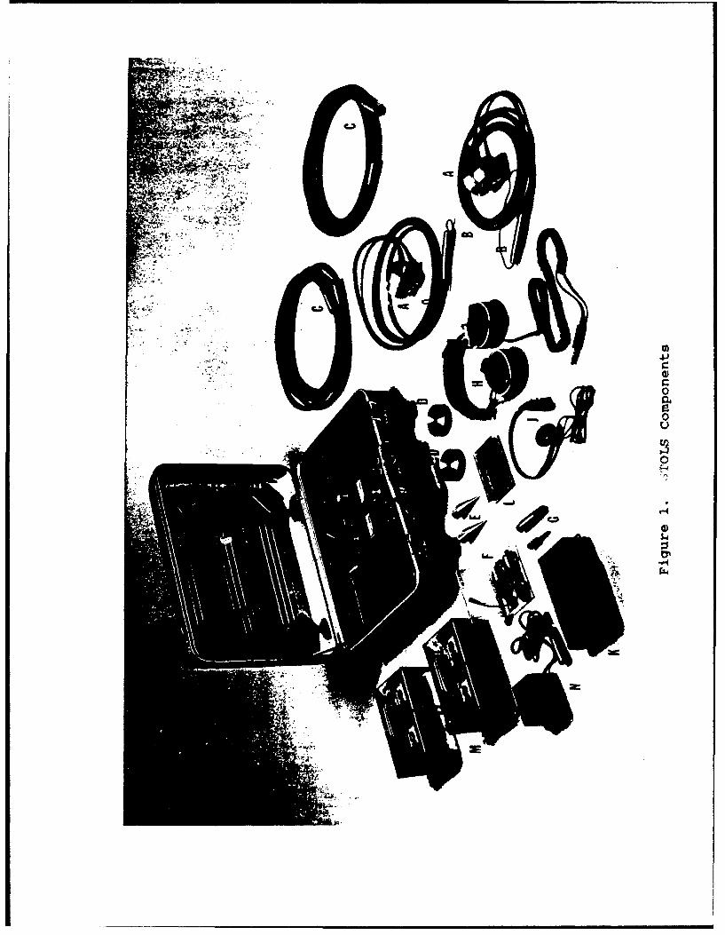
repair if necessary. Each unit conatins (see Figure 1):
A 2 Geophone Transducers w/ 10 feet Cables(Mark Products Li-B's)
B 2 Shorting or Shunting Plugs for the GeophonesC 1 Extension Cable, 20 feet, for Geophones
or a MicrophoneD 2 Brass Geophone Bottom WeightsE 2 Aluminum Geophone Soil SpikesF 1 Miniature Microphone and Pre-Amplifier with BatteryG 1 Adapter Jack to Plug Miniature Microphone
into Extension CableH 1 Large Speaker HeadsetI 1 Small Speaker HeadsetJ 1 Battery ChargerK 1 Two Channel Portable Tape Recorder
w/ Operation InstructionsL . Iron Oxide Cassette TapeM 1 Jel Cell Battery, 6 VoltN 1 XENOTRONIX 24 Volt Fast/Float Battery Charger
NOT SHOWN 4 Extra AA Alkaline Batteries for the Tape Drive2 Extra 1.5 Volt Batteries for the Microphone
The STOLS unit is designed to operate for 24 hours continuously
on one battery charging. If the unit is switched off when not in
use, several days of operation can be expected. The STOLS
battery can be recharged by plugging the charger into any 110 V
60 Hz single phase wall outlet and then plugging the charger
output terminal to either of the ports on the STOLS battery. Any
standard small appliance electrical converter used for
international travel e.g. 208 V, 50 Hz to 110 V, 60 Hz, can be
attached to the transformer and then used to charge the STOLS
battery. Full cycle battery charging takes 8 to 10 hrs. Two
other battery operated devices are in the STOLS system. One is
the tape recorder that operates on 4 AA alkaline batteries. Four
8
9.0
-04
hours of coitinuous operation can be expected with one set of new
alkaline batteries. It is also possible to directly power the
tape recorder from the STOLS battery. When configured in this
manner, the battery adapter cable is plugged into the "AUX TAPE
POWER" port on the STOLS unit and then plugged into the "DC in
6 VI" jack on the tape recorder. The other battery powered device
is the miniature microphone. This unit uses a standard 1.5 Volt
miniature battery available at most electronic supply houses.
Twenty hours of continuous operation is possible with this unit.
Toggle the switch on the pre-amplifier box (the small case before
the microphone) to the "OFF" position when not in use.
9. The STOLS units are specifically designed to be air
transported as "carry-on" baggage. It is not recommended to
check the units as baggage without additional packaging. If a
unit needs to be shipped, it should be packed in a durable
freight box with proper padding such as bubble wrap, or
styrofoam.TurninQ On STOLS Units
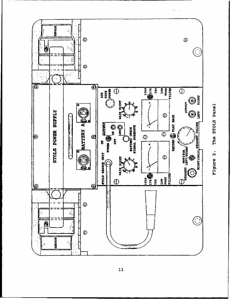
10. The STOLS unit is turned on by first plugging the jack
on the cable coming from the panel below the words "STOLS SEARCH
UNIT" to either port on the STOLS battery. Switch the toggle on
the panel marked "POWER" to "ON", (see Figure 2). The battery
indicator light should be green "OK" or red "LOW". If the
battery is low, it needs to be charged. When the power toggle is
"ON", push the red "BATTERY CHECK" button. The needles on both
VU meters should go way to the right past the red portion of the
dial if the STOLS battery is fully charged. If the VU meter
needle rev.-ins in the black portion of the dial the battery
requires charging. The STOLS 6 Volt jel cell battery should be
charged for 24 hours once every 30 days to maintain the battery
shelf life and keep the unit in a ready-to-operate mode. When
the STOLS unit is not in use, the cable connecting the battery to
the operating panel should be disconnected.
10
ý-: L:3
0a 1
al
0 ,EA0
i9t I
113
4.4" NO v.
ED.in
LEV

Geophone Sensorsii. Two specially manufactured geophones are provided with
each STOLS unit. These instruments are used to monitor elasticwaves. CAUTION: The special geophones supplied with the STOLShave been determined by special studies to be the best sensor forthe task of finding survivors in debris. They are delicate andtherefore must be handled with some care. The following rulesMUST be strictly observed.
a. Never drop or shake a geophone.b. Always ensure that the shorting or shunting plug is
connected to the end of the cable before moving thesensor. It is also acceptable to move a geophoneif it is plugged into a STOLS unit.
c. Always carry the geophone sideways, i.e. with itslong axis perpendicular to the ground.
Remove the two geophones from either the padded compartments onopposite side of the STOLS battery and unwrap the cable. Notethat the end of the cable has a cap or plug. THIS IS IMPORTANT !This cap serves to "shunt" or to short the geophone. When thecap is on the end of the cable, it keeps the internal mechanismin the geophone "braked" or fixed into position. Do not move,carry, or handle the geophones unless this cap is on the end ofthe cable or the geophone is plugged into the STOLS unit. To dootherwise may damage or break this very sensitive instrument.KEEP THE CABLE CAPS ON AT-ALL TIMES WHEN THE GEOPHONES ARE NOTPLUGGED INTO THE STOLS UNITS. Remove the shunt cable caps whenthe geophones are not being handled or jostled and plug thecables into the right and left sockets on the sides of the STOLSunit marked "INPUT RIGHT" and "INPUT LEFT". When the STOLS isfunctioning with both geophones, signals from the right geophonewill be monitored with the right side of the head set and viceversa. When using the headset, speakers marked "RIGHT" and"LEFT" should be placed over the right and left ear. Insert theheadset plug into the receptacle marked "HEADSET". Locate thegeophones in a position that will be used to monitor for survivorresponses. These sensors need to be placed upright for best
12

sensitivity and signal response. The more the sensor tilts from
a vertical axis the lesser the response and sensitivity of the
instrument. An off-vertical tilt of less than 10 degrees is
satisfactory, and "eyeball" leveling is sufficient. When
operating on rubble, the brass geophone base should be snugly
attached to the bottom of the geophone. If the instrument is to
be utilized on soil or sands, the spikes should be screwed onto
the geophone bottom in place of the brass plates. If more
cabling is required for a geophone, attach the 20 foot extension
cable between the STOLS unit and the sensor. Up to three
extension cables may be connected together without a significant
loss of signal.
Microphone
12. The miniature microphone may be used in place of either
geophone if it is desired to monitor acoustic waves. When
utilizing the microphone, be sure that: (1) The battery terminals
are clean (rub with an eraser). (2) The battery is properly
inserted in the pre-amplifier. (3) The exterior switch is in the
"ON" position. To plug the microphone into the STOLS unit or
into the extension cord, use the adapter jack provided. When the
STOLS is in field use, it is useful to tie string, etc. to the
adapter jacks and other small parts to prevent them from "falling
through cracks" in the debris pile. The microphone may also be
used to place messages on the cassette tape by the STOLS operator
or inserted into a debris pile to listen for verbal responses
from survivors. A typical insertion system is to tape the
microphone and cable onto long flexible pole such as a fiber
glass rod or 1/2" PVC pipe. Protect the microphone by not
placing it directly on the tip or end of the pole. As with the
geophones, several extension cables may be linked together to
give a long reach into hard to search places. In addition the
microphone is not water proof, a sacrifice made to increase its
sensitivity.
13
Using Only One Channel
13. It is advantageous in certain instances to use only one
rather than both channels on the STOLS system. A toggle switch
on the panel marked "LEFT ONLY / RIGHT ONLY" and "BOTH" allows
this to be done. This switch allows both left and right sensors
to be simultaneous monitored or only one sensor at a time with
the other sensor switched off. If only one microphone or
geophone is to be monitored, plug the cable into the right side
of the STOLS unit and toggle to "RIGHT ONLY". If the left
channel VU appears to be moving but no sound is reaching the left
headset, it may be due to the fact the toggle was inadvertently
placed in the wrong position.
Acoustical and Elastic Wave Freauencies
14. Rescue experience and field tests have shown that voices
or taps from trapped persons are of specific spectral
frequencies. With this in mind, it is possible to electronically
separate or filter out many unwanted noises or interfering
signals. Elastic wave signals from persons tapping are generally
in the 25 to 50 Hz range. This is near the lower range of human
hearing and often elastic waves from vigorous pounding in the
debris pile will be identified as strong but low pitched thumps.
To monitor elastic wave taps with the geophones, place the right
and left channel toggle switch at 175 (a 175 Hz low pass filter).
This greatly reduces unwanted noises above 175 Hz. Tests andexperience have shown that voices do not travel well from debris
piles. However acoustic responses below 350 Hz appear to
propagate much better than those above 350 Hz. Hardly any voice
generated acoustic waves above 1000 Hz propagate well from debris
or rubble, but if the void space in the debris is fairly large
and continuous from the victim to the STOLS microphone, a voice
response in the range 350 to 1000 Hz should be detectable. Thus
when monitoring with microphones have the frequency toggles set
at 350 or 1000. Remember that more interfering signals will be
heard with the 1000 Hz filter than the 350 Hz filter. Both
filter switches must be set to the same cutoff frequency to
14
preserved matched phase response from each channel. When using
the STOLS geophones start monitoring with the filters set at 175
Hz. The normal setting for the microphone is 1000 Hz. The 350
setting is used with the microphone in the presence of
interfering noises.
Adjustinq the Amplification or Gain
15. The amplification or electronic gain of left and/or
right channel(s) must be set or adjusted. With the power on, the
filters set and sensors placed and connected, increase the
electronic gain by turning the left and right knobs marked "GAIN"
to greater numerical numbers. Monitor the increasing
amplification level on the appropriate VU meter. The needle
should move back and forth but should for the majority of the
time remain in the black colored portion of the dial. If the
needle remains in the red portion of the VU meter, the gain is
too great and needs to be reduced. Plug the headset into either
the jack marked "HEADSET" on the panel or into the external
headset jack adjacent the STOLS carrying handle. Two headsets
can be used simultaneously if desired. Adjust the sound volume
to a comfortable level by increasing the secondary amplification
with the knob marked "HEADSET VOLUME". Test the system now by
very lightly tapping on either the geophones or the microphone.
When this is done, the VU meters should deflect and an audible
sound should be heard in the headset. If this is not the case,
retrace the set-up procedure to identify the cause.
Using the Cassette Recorder
16. Each STOLS unit has a built in stereo cassette recorder.
Collection of signals by tape recording is an important task for
the STOLS operator. Sometimes a signal or noise may be heard
which cannot be identified but should be re examined by a more
seasoned operator. Many times uncertain sounds which were
recorded can be scrutinized using more sophisticated data
processing equipment and clearly identified as to their source.
Data collected on disaster sites can be used to train other STOLS
operators. Once the STOLS amplifier levels have been set so that
15

the VU needles remain in the black colored portion of the dial
most of the time, the STOLS unit can be used with the recorder.
Adjusting the amplifiers by monitoring the VU meters sends nearly
the optimum voltage level of signal from the STOLS to the tape
recorder. This greatly enhances the capability of post
processing weak and uncertain signals and sounds. Adjust the
toggle on the STOLS panel which reads "RECORD/PLAYBACK" to the
"RECORD" positicn. Open the box on the right side of the control
panel which contains the tape recorder. Insert the plug on the
black cable from the STOLS unit into the jack on the tape
recorder marked "INPUT". Turn on the tape recorder in the RECORD
mode. Instructions on the use of the tape recorder will not be
addressed here, as these are covered in the operational guide
provided by the manufacturer and included in the STOLS unit. To
check if the signal is being recorded, the smaller head set can
be plugged into the tape drive or the varying signal intensity
lights on the recorder can be visually monitored. To play back a
tape through the operating STOLS unit, adjust the
"RECORD/PLAYBACK" toggle on the STOLS unit to the "PLAYBACK"
position. Insert the plug on the black cable from the STOLS unit
into the jack on the tape recorder marked "OUTPUT". The tape can
be monitored through the headset and the signal volume adjusted
to an optimum level by turning the "HEADSET VOLUME" knob on the
STOLS panel. If signals are not recorded or cannot be played
back with the tape recorder, retrace the adjusting and connecting
steps with the STOLS units and the operation of the tape recorder
until the problem is identified. Always use normal or iron oxide
cassette tapes with the STOLS recording unit. These are
generally the least expensive type of cassette tape and have
superior frequency range below 100 Hz when compared to chrome
oxide or other types of recording tapes.
Repositioning the STOLS Unit
17. When the STOLS unit is ready to be relocated, first
UNPLUG THE GEOPHONES FROM THE STOLS UNIT AND REPLACE THE SHUNT
CAPS ON THE CABLE ENDS BEFORE THE GEOPHONES ARE HANDLED OR MOVED.
16

Turn all power switches to the "OFF" position and pick up the
gear.
Site Operation of STOLS Teams
18. STOLS teams are organized with each STOLS units. Twoto four persons are normally formed into a team and assigned toeach STOLS unit. This allows a nearly continuous operation atthe disaster site with the STOLS unit handed off from one sectionof the team to the other. The teams are trained to worktogether, with the "off-duty" team members assisting the "on-duty" team in tasks such as securing of rations and potabledrinking water, watching personal belongings, maintenance of teamgear, and administrative tasks. In addition STOLS team membersat the disaster site watch out for each other, remembering thatexcessive physical and mental fatigue can lead to mistakes andinjuries. Safety is a critical part of STOLS operation. Watchout for your buddy and realize teamwork is the key to the successof survivor detection and location.
Disaster Site Operations19. Disaster sites generally are confusing but not
impossible affairs. It is important to work along side and inconcert with the efforts of the Incident Commander at thedisaster location. He or she will designate a location for theSTOLS teams to stage their efforts which is relatively close tothe collapse structures. This may be a school room, spot in anarmory, or a tent in a park. The Incident Commander will thenprovide a reporting procedure as to who in the agency to furnisha daily report and with whom the STOLS teams should coordinate.In past technical search operations acoustic / seismic listeningteams have worked closely and in coordination with US&R dog teamsand medical personnel. It is important that a designated personfrom the STOLS teams coordinate with the dog team leader(s)concerning areas searched, possible live survivor indications,and methods of field markings. It has been standard practice at
17
past disasters that locations in debris where dogs have indicated
a possibility of a survivor are checked by technical search teams
for any indication of the presence of a trapped person.
STOLS Teams ODerating in GrouDs
20. STOLS teams generally operate best in groups. Often
there is a temptation to disperse the teams over a wide area toapparently increase the number of sites investigated. However,by placing only one or perhaps two STOLS units and operators per
building, large areas of the collapsed structure are not
effectively monitored for survivor response. As the STOLS teamwork their way over the structure, survivors can be effectively
"worn out" and unable to give a strong or loud response when a
STOLS team eventually places the sensors within effective
listening range. It is therefore imperative that a sufficient
number of STOLS teams are assigned to monitor a collapsed
structure so that a reasonable survivor response is detected soon
after the STOLS teams are set up and begin listening.
Controlling Noise Pollution and Types of Interfering Noise
21. The STOLS units have extremely sensitive sensors which
respond well to frequencies associated with taps from survivors
in rubble. In a disaster area, many other acoustic and seismic
noises will be present. Some such as background noise, produced
by wind are natural in occurrence. Most others at the disastersite will be the result of cultural activity. These include: (1)
Construction equipment, such as cranes, bulldozers, jackhammers,
pumps, air compressors, generators, etc. (2) -ixed and rotor wing
aircraft overhead. (3) Sirens from various emergency vehicles.(4) Heavy road traffic. Noise levels at an operation site may
reach an order of magnitude greater than those in normal day
activities. Although the STOLS units are designed to remove and
filter as much of these interfering noises as possible, noise
pollution control for a city block or more around the searched
area is generally necessary. In addition, the air space above
the searched area needs to be controlled and restricted for 10
nautical miles around the disaster site. Generally, local law
18

enforcement and disaster response agencies will aid in ground
noise pollution control at coordinated times. The Federal
Aviation Agency under the US Department of Transportation has
upon request, traditionally restricted airspace to aid disaster
operations. Invariably, the overall noise level from cultural
sources greatly abates after sunset and does not increase again
until sunrise. Nighttime is therefore the most effective time
for STOLS unit operation and should be designated as the primary
time for the technical search effort. Although the technical
search for survivors should take place on a 24 hour basis, night
time efforts have proved to be more effective. During such quiet
time operations, footfalls can be easily detected and it may be
necessary to request persons on the site to be seated still while
the monitoring is being conducted.
Common Collapse Patterns and Voids
22. Buildings of differing construction collapse in a
variety of ways. It is important to be able to recognize various
types of these structures and their collapse patterns. An
understanding of these failure patterns will assist the STOLS
operators in determining likely areas where survivors may be
trapped. Voids are created in most collapses into which
survivors either have been able to move, or where some may have
been located when the building failed. In many instances,
buildings have been described to have disintegrated "in slow
motion" during an earthquake. Generally the more prolonged the
destruction of a building the greater the likelihood for voids to
be present and hence the increased chance for survivors.
Particular areas of interest are regions where a building has
strong structural elements such as stairways and elevator shafts.
The walls of basements also represent a solid member and large
voids are often found adjacent to these. Typical failure
patterns which create voids are in indicated in Figure 3. These
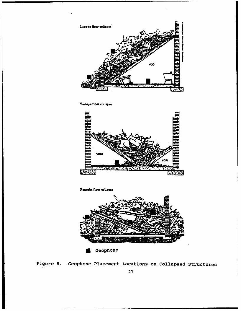
general types of collapses are: (1) The Lean-To. One side of a
floor falls and the other side may be partially supported.
19

LA&D-to floor Collapse
V-shape floor collapse
Pantsiw floor toliapse
Figure 3. Typical Building Failure classification
20
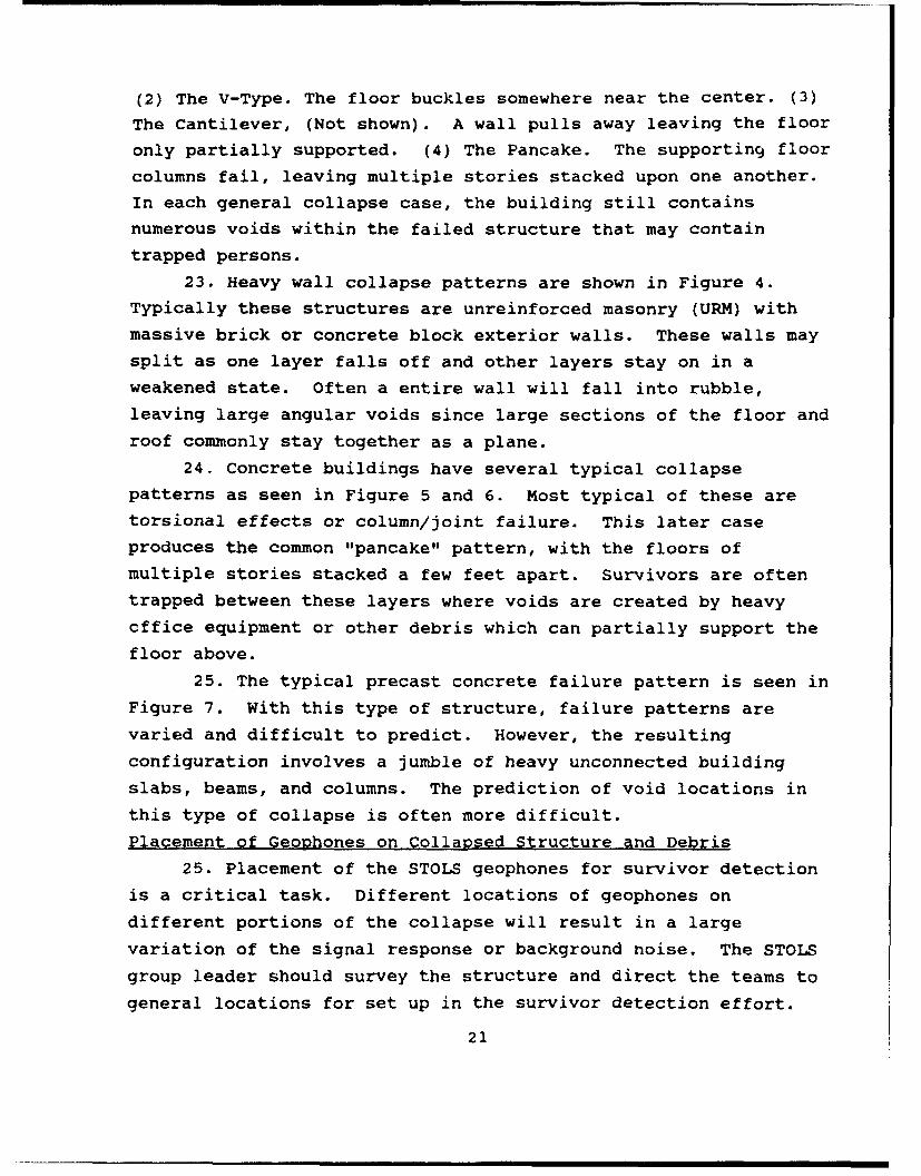
(2) The V-Type. The floor buckles somewhere near the center. (3)
The Cantilever, (Not shown). A wall pulls away leaving the floor
only partially supported. (4) The Pancake. The supporting floor
columns fail, leaving multiple stories stacked upon one another.
In each general collapse case, the building still contains
numerous voids within the failed structure that may contain
trapped persons.
23. Heavy wall collapse patterns are shown in Figure 4.Typically these structures are unreinforced masonry (URM) with
massive brick or concrete block exterior walls. These walls maysplit as one layer falls off and other layers stay on in a
weakened state. Often a entire wall will fall into rubble,leaving large angular voids since large sections of the floor and
roof commonly stay together as a plane.
24. Concrete buildings have several typical collapse
patterns as seen in Figure 5 and 6. Most typical of these are
torsional effects or column/joint failure. This later case
produces the common "pancake" pattern, with the floors of
multiple stories stacked a few feet apart. Survivors are often
trapped between these layers where voids are created by heavy
cffice equipment or other debris which can partially support the
floor above.
25. The typical precast concrete failure pattern is seen in
Figure 7. With this type of structure, failure patterns are
varied and difficult to predict. However, the resulting
configuration involves a jumble of heavy unconnected building
slabs, beams, and columns. The prediction of void locations in
this type of collapse is often more difficult.
Placement of Geophones on Collapsed Structure and Debris
25. Placement of the STOLS geophones for survivor detection
is a critical task. Different locations of geophones on
different portions of the collapse will result in a largevariation of the signal response or background noise. The STOLS
group leader should survey the structure and direct the teams togeneral locations for set up in the survivor detection effort.
21

CONCRETE BUILDING COLLAPSE PATTERNS
SE LTA, ,_MAJOR FORCE IS IN THE I"IMASSIVE FLOOR WEIGHT
LOAD P IS OFFSET SOLARGE A DELTA THAT ITKEEPS GOING OVER
P-DELTA EFFECT
P f CONCRETE IN COLUMNS ISOFTEN NOT WELL ENOUGHCONFINED BY REBAR TIESAND WHEN CONC FALLS OFFTHE VERT REBAR POPS OUT
COLUMN/JOINT FAILURE
P
S"" PROPERTY LINE- " WALLS- ON TWO
p OR THREE SIDES
TORSION EFFECT
Figure 4. Typical Heavy Floor Building Failure Patterns
22
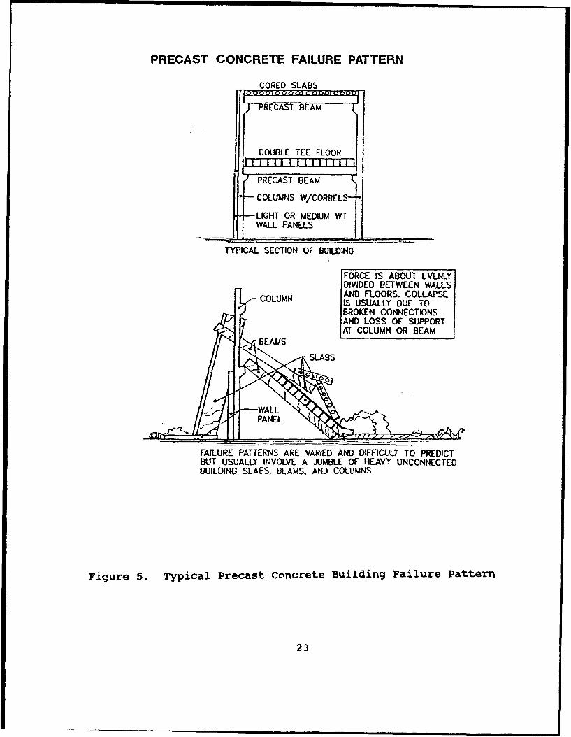
PRECAST CONCRETE FAILURE PATTERN
CORED SLABS
--RCAST BAM
DOUBLE TEE FLOOR
S PRECAST BEAM(
" COLUMNS W/CORBELS-
-LIGHT OR ME.DIUM WTWALL PANELS
TYPICAL SECTION OF BUILDING
FORCE IS ABOUT EVENLYDIVIDED BETWEEN WALLS
SCOLUMN AND FLOORS. COLLAPSEIS USUALLY DUE TOBROKEN CONNECTIONSAND LOSS OF SUPPORTAT COLUMN OR BEAM
BEAMS
FAILURE PATTERNS ARE VARIED AND DIFFICULT TO PREDICTBUT USUALLY INVOLVE A JUMBLE OF HEAVY UNCONNECTEDBUILDING SLABS, BEAMS, AND COLUMNS.
Figure 5. Typical Precast Concrete Building Failure Pattern
23

CONCRETE BUILDING FAILURE PATTERNSWE..iT IS ABOUT EVENLYDISTRIBUTED BETWEENFLOORS AND WALLS
.- . _- _±S A W L
OVERTURNING FAILED HAWLOR
FOUNDATION FAILURE
SOFT 1ST STORY FAILURE OF 1IST STOReY
LCOLUMNS
0:- 0,0. '
SHORT WALL COLUMN FAILURE OF COLUMNS& POSSIBLE COLLAPSEOF STORY
Figure 6. Additional Concrete Building Fail-are Patterns
24
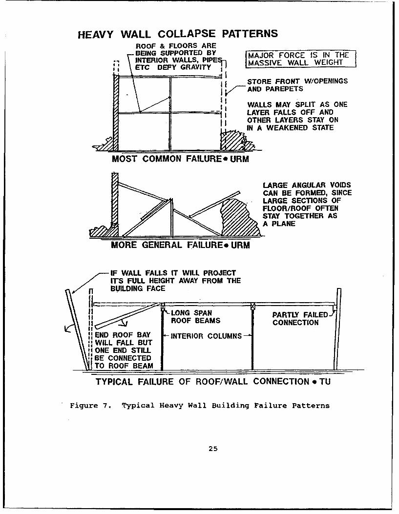
HEAVY WALL COLLAPSE PATTERNSROOF & FLOORS AREBEING SUPPORTED BY MAJOR FORCE IS IN THEINTERIOR WALLS, PIPE IMASSIVE WALL WEIGHT
":; ETC DEFY GRAVITY
STORE FRONT W/OPENINGSAND PAREPETS
-I[ WALLS MAY SPLIT AS ONEI.. LAYER FALLS OFF AND
OTHER LAYERS STAY ONIN A WEAKENED STATE
MOST COMMON FAILURE* URM
LARGE ANGULAR VOIDSCAN BE FORMED, SINCELARGE SECTIONS OFFLOOR/ROOF OFTENSTAY TOGETHER ASA PLANE
MORE GENERAL FAILURE* URM
IF WALL FALLS IT WILL PROJECTITS FULL HEIGHT AWAY FROM THE
, BUILDING FACE
ROOFBEM PARTLY FAILEDROOF BEAMS CONNECTION
" END ROOF BAY INTERIOR COLUMNS:: WILL FALL BUT
ONE END STILL, BE CONNECTED
TO ROOF BEAM
TYPICAL FAILURE OF ROOF/WALL CONNECTION * TU
Figure 7. Typical Heavy Wall Building Failure Patterns
25
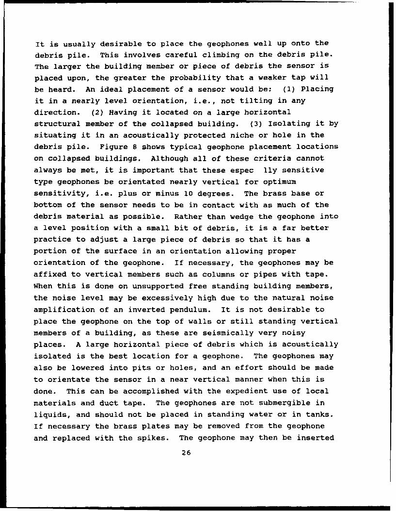
It is usually desirable to place the geophones well up onto the
debris pile. This involves careful climbing on the debris pile.
The larger the building member or piece of debris the sensor is
placed upon, the greater the probability that a weaker tap will
be heard. An ideal placement of a sensor would be: (1) Placing
it in a nearly level orientation, i.e., not tilting in any
direction. (2) Having it located on a large horizontal
structural member of the collapsed building. (3) Isolating it by
situating it in an acoustically protected niche or hole in the
debris pile. Figure 8 shows typical geophone placement locations
on collapsed buildings. Although all of these criteria cannot
always be met, it is important that these espec fly sensitive
type geophones be orientated nearly vertical for optimum
sensitivity, i.e. plus or minus 10 degrees. The brass base or
bottom of the sensor needs to be in contact with as much of the
debris material as possible. Rather than wedge the geophone into
a level position with a small bit of debris, it is a far better
practice to adjust a large piece of debris so that it has a
portion of the surface in an orientation allowing proper
orientation of the geophone. If necessary, the geophones may be
affixed to vertical members such as columns or pipes with tape.
When this is done on unsupported free standing building members,
the noise level may be excessively high due to the natural noise
amplification of an inverted pendulum. It is not desirable to
place the geophone on the top of walls or still standing vertical
members of a building, as these are seismically very noisy
places. A large horizontal piece of debris which is acoustically
isolated is the best location for a geophone. The geophones may
also be lowered into pits or holes, and an effort should be made
to orientate the sensor in a near vertical manner when this is
done. This can be accomplished with the expedient use of local
materials and duct tape. The geophones are not submergible in
liquids, and should not be placed in standing water or in tanks.
If necessary the brass plates may be removed from the geophone
and replaced with the spikes. The geophone may then be inserted
26
ZAnu~to floor collapse
V-shape floor collapse
Pancake floor eColapse
UGeophofle
Figure 8. Geophone Placement Locations on Collapsed Structures
27

into soil or wedged into cracks or joints.
STOLS Team and GeoDhone Spacina
26. The separation and spacing of the STOLS teams and hence
the geophones over and around a collapsed or damaged structure
needs to be chosen so the resulting response of a trapped person
may be identified. Under quiet conditions such as found at night
or with careful daytime noise pollution control a reasonably good
tap can be normally detected with the STOLS unit for a range of
approximately 75 feet. Often taps can be detected for even
greater ranges, but the certainty of identification decreases
with distance. The maximum range that any tap may be monitored
is in the range of 150 to 175 feet. To be conservative the
aeoDhones should be Rlace apDroximately 25 to 40 feet apart.
Conditions vary considerably from site to site and a tap test
should be conducted at each location to determine the effective
distance a reasonably strong tap may be detected. This test is
generally conducted by tapping with a piece of debris on the
ground. A tap test also assures the operator that the STOLS
units are functional and properly adjusted. Once the effective
range for tap detection is established for the site and
conditions, the STOLS teams may be effectively spaced so that no
gaps occur in the coverage. Field tests demonstrate that sound
travels fairly well into the debris pile but poorly out of it.
The range that a trapped person may be able to hear a request
from a megaphone for a tap can be greater than the distance to
which the tap is detectable. Therefore the collapsed structure
needs to be adequately covered with STOLS teams and sensors.
Challenaing the TraDRed Person to Tap
27. It is necessary to challenge the trapped person to
respond once the STOLS teams have been deployed on the structure.
Field tests have demonstrated that taps rather than voice
responses are detectable significantly greater distances through
the debris pile. Two current schools of thought describe the
best way to request a person to tap. One technique is to use a
tapping rod. A series of five quick taps followed by two slower
28
taps is performed at the surface. This will alert the person(s)in the debris to answer with taps. Arguments against using thismethod are that if the debris pile is large, persons located morethan a few tens of feet from the tapping rod may not hear therequest. Another school of thought is to use a megahorn andrequest for taps. It is necessary to challenge the trappedperson their native language. Arguments against using a voicechallenge are that persons trapped may hear a distorted voicethrough the debris pile and not understand the directions. Theymay then try to respond by voice rather than by taps. Until onetechnique clearly displays itself as greatly superior to another,it is advisable to use both techniques, first the tapping rod andthen the megaphone. It is important to try to have the trappedperson respond with taps rather than shouts if they are able.Field tests conclusively demonstrate that a good tap from aperson well into the debris pile can be detected a significantlygreater distance than a voice response. In addition, tests andrescued survivor interviews indicate that a person trapped wellinto a collapse structure can generally hear a voice challengethrough megahorns or other voice amplification devices.
28. The length of time a building site should be monitoredbefore the STOLS teams move onto another location is uncertain,Generally, once the teams have been place and have been activelylistening for survivors for 10 minutes or so it is advisable tomove to another site. Before moving to a new vicinity it isoften advisable to have the STOLS te nas shift to new positions onthe same debris pile and relocate the geophones. Queries shouldbe repeated for survivors to tap. Once a collapsed building orarea has been monitored by the STOLS teams it should be placed ona priority list for a later return. In many instances survivorshave been detected and located after a second or even thirdreturn to a collapse site. Many of these persons were unaware ofearlier search and rescue efforts.
29
Use of Microphones to Listen for Voice Responses
29. Not all survivors in debris have the means to produce
taps. Infants, totally pinned persons, or completely exhausted
individuals do not or may not have the means to tap. Although it
is recognized that voices do not travel well through debris, a
cry for help may be the only means these persons have to request
assistance. To recognize and locate these cases the STOLS units
contain a miniature microphone which may be used on either
channel. Microphones and extension cables from other STOLS units
may be used in conjunction to form one or more dedicated units
just for acoustical search. The most practical way for
monitoring survivor's cries for assistance has been found to tape
the microphone and extension cable(s) onto a long flexible pole
and insert this pole into gaps in the rubble as far as possible.
Field expedient insertion devices may be fabricated from such
sources as PVC pipe, cane fishing poles, fiber glass surf fishing
rods or connectable flexible poles used by chimney sweeps. Note:
It is not recommended to use metal poles unless it is certain
that all electrical power sources are disconnected. In past
search efforts it has been found possible to drive a cast iron or
steel pipe through a portion of the debris into a void and insert
the miniature microphone through the pipe. Other microphones, in
addition to the miniature device supplied with the STOLS units
may be effectively used. The only restriction is that the
microphone have a standard impedance.
Located Survivor
30. A positive response from a survivor should be
authenticated at once. This can be accomplished by playing back
the recorded channels on the tape drive and having other persons
verify the signal. Several steps then need to be taken: (1) The
Incident Commander must be notified a possible survivor has been
located. (2) The supporting rescue and medical teams need to be
alerted. (3) Techniques need to be taken to locate the trapped
person as accurately as possible. However, note that buildings
containing one survivor often contain more. Do not focus the
30

entire search effort on the response of one person, the rest of
the area must be searched for additional survivors. All STOLS
units should recheck their tape recorded efforts to insure that
the same or another survivor's response has not been overlooked.
STOLS units receiving a positive indication of a trapped person
should temporarily stay in place. At least one geophone
definitely receiving a response from a trapped person should
remain in the same position. Those not receiving a signal or
obtaining only having a weak reply should move to a location
which would appear to be more favorable. All STOLS units
tracking a responsive survivor should be adjusted to the same
gain or amplification level and the same filter settings
whereever it is practical. In this manner the strength of the
signal from the trapped persons response may be used to spatially
locate the person(s) within the debris. Generally the stronger
the signal, the closer the person would be to a geophone
location. The relative strength of the signal when the gain
levels are the same can be easily determined by how great the
needle deflects on the VU meter. It is important not to tie up
all the technical search effort for a great deal of time at a
single site where a survivor is located. Once someone has
responded and has been located as accurately as possible, a STOLS
unit(s) should stay to monitor the survivor(s) and to assist the
rescue teams in identifying the location of the survivor(s). The
remainder of the group should move to the next site and continue
the search. It is critical that the STOLS personnel NOT attempt
to immediately uncover any trapped person. Individuals covered
by debris for any length of time and uncovered without on site
medical assistance may develop acute renal failure as a cause of
traumatic rhabdomyolysis or crush syndrome. Survivors should
only be uncovered in the presence or after treatment by trained
medical personnel. Many trapped persons have expired after being
uncovered or removed due to the lack of needed medical assistance
during the extraction effort.
31

31. A typical search procedure with a STOLS unit containing
four geophones would be as follows. The geophone sensors would
be placed in a square pattern at favorable locations on the site
with a 25 to 40 foot spacing between sensors. Survivors would be
challenged to respond with a tapping rod and megahorn. Two
sensors at a time would be monitored. The signal strength of a
answer from a trapped survivor would be compared between
channels. The geophone having the strongest response will remain
in place and the other geophones moved to new locations to "zero-
in" the location of greatest signal level. Two or more STOLS
teams hearing the same person respond would work toward each
other until a final peak response location is achieved.
Record Keeping
32. Each STOLS group leader has the responsibility of
keeping a work diary. Information should include as a minimum:
the names of the STOLS operators, time of day, street addresses
or locations, building or business names if known, sketch map of
the site with the STOLS monitoring locations, indications of any
survivors, and any other observations that the group leader feels
necessary to record. The STOLS teams, if working independently
need to maintain similar records. In addition each STOLS
operator has a responsibility to voice record information onto
the STOLS tape recorder such as: the location, time of day, site
conditions, amplifier gain levels, and any information the
operator feels to be significant.
Marking the Site
33. Many search and rescue efforts are comprised of local,
state, national and international assets which operate under the
local incident commander. Due to the wide diversity of effort,
standard site markings have been established which are spray
painted at each building site. These hieroglyphics have been
developed by agreement among the search and rescue community.
This system is found in Appendix A. It is important that this or
any other marking system at the disaster site be understood and
used by the STOLS operators. It is critical that if additional
32
or different marking systems are used by other search teams,
local search and rescue organizations, or international groups,
that these systems be recognized and interpretable. It is
important that the markings by the STOLS teams be placed on the
buildings so that they represent a fairly permanent record and
are easily seen by other organizations. PainLed symbols on
sheets of plywood or other debris which can be easily erased,
moved, hidden, or altered are discouraged. Attempt to leave a
tamper-resistant indication of the technical search effort
preformed by the STOLS teams. At past disasters persons have
erased search team markings in order to encourage additional
monitoring of a collapsed structure.
Maintenance and Repair of the STOLS UNITS
34. The STOLS units have been developed to be transportable
and operable in a wide variety temperatures and climatic
conditions. Standard and reasonable care and maintenance will
keep the units in good working condition. All dry cell batteries
should be replaced twice a year. The two jel cell batteries
which are the main power source for the STOLS unit should be
charged monthly. These power units should be replaced every two
years. After charging the STOLS unit, it should be set up and
all functions and accessories checked for good performance. This
includes checking the geophones, microphone, tape recorder,
filter functions, indication lights, and accessories. If a unit
needs to be repaired or serviced, it should be shipped to the
Earthquake Engineering and Geoscience Division, US Army Corps of
Engineers Waterways Experiment Station, 3909 Halls Ferry Rd,
Vicksburg, MS, 39180. Emergency field servicing is possible, and
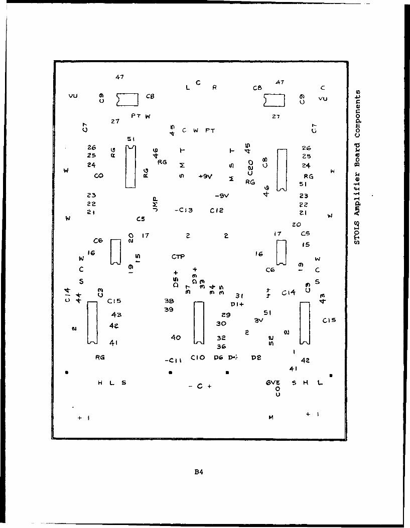
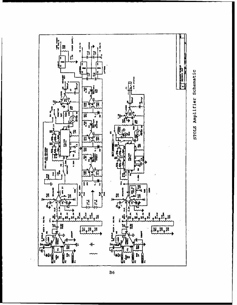
circuit diagrams, board layout, and part lists are included in
Appendix B.
Safety
35. Safety is a continual concern at all disasters. Live
electrical wires may be present. Natural gas lines may be broken
with fire or an explosion a possibility. Unstable and damage
structures may collapse or shed debris during an aftershock.
33
Debris piles may shift during climbing operations. Always
consider safety when operating STOLS units. The buddy system is
used to check on the physical and mental well being of STOLS
team members.
Personal Gear and EquiDment36. STOLS team members need to be ready to go on very short
notice. It is necessary to keep a minimum amount of equipmentready for rapid deployment. The following is the recommended
basic equipment for operation.
List of Required Equipment for STOLS teamsa. Boots (Mountaineering) for Talus Slope Climbingb. Durable Flashlight w/ Additional Batteries and Bulbd. Chemical Light Stickse. Canteen w/ Water Purification Tabletsf. 2-Way FM Radio (with proper frequency)g. Surgical Mask (2)h. Identification Bracelet/Tagi. Pocket Notebook, 100% Rag Paper e.g. Survey Notebookj. Waterproof Ink Pensk. 6 - 8 MRE's (Meal, Ready to Eat)1. 1 Roll Grey and Duct TapeZ. Building Markers i.e. spray paint, lumber crayons,
surveyor tapen. Safety goggleso. First Aid Kitp. Megaphone
Suggested Personal Gear and Equipmentq. Socksr. Seasonal Clothing, two changess. Utility Tool, eg Swiss Army Knifet. Helmet w/ Mountable Lightu. Leather Gloves (2 Pair)v. Extra Safety Eye Glassesw. Compassx. Foul Weather Geary. Sleeping Bagz. Personal Hygiene Accesboriebaa. Insect Repellentbb. Sun Screencc. Mosquito Netting (According to Location)dd. Wrist Watchee. Credit Cards and Telephone Calling Cardsgg. Government Identification Cardff. Cashhh. Pack or Duffle Bag
34

BIBLIOGRAPHY
Chen, Y., T. Kamling, F. Chen, Z. Gao, Q. Zou, and Z. Chen, 1988.The Great Tangshan Earthquake of 1976 - An Anatomy of a DiasterState Seismological Bureau, Beijing, PRC, Pergamon Press, 161 pp.
CINCFOR Catastrophic Earthquake Response Plan, (Federal UrbanSearch and Rescue), 5 April 1991., Volumne 5, Headquaters,US Army Forces Command, Fort McPherson, GA 30330-6000Attn: FCJ5 - MD
De Bruycker, Marc, Donanto Greco, Isidoro Annino, Maria A. Stazi,Nicola De Ruggiero, Maria Triassi, Yves P. De Kettenis, andMichel F. Lechata, 1983. "The 1980 Earthquake in Southern Italy:Rescue of Trapped Victims and Mortality", Bulletin of the WorldHealth Organization, Vol 61, No. 6, pp.1021-1025
Downey, Ray, 1992. "The Rescue Company", Fire Engineering Booksand Videos, Saddle Brook, New Jersey, 328 pp.
McGroarty, Mike, 1989. "Rescue from Collapse Buildings", Rescue,Vol 2, No. 1, pp. 24-30.
Rojahn, Christopher, 1988. "ATC-20, Proceedures forPostearthquake Evaluation of Buildings", Applied TechnologyCouncil, Redwood City, California, 153 pp.
Rojahn, Christopher, 1989. "ATC-20-1, Field Manual:Postearthquake Safety Evaluation of Buildings", AppliedTechnology Council, Redwood City, California, 114 pp.
Rojahn, Christopher, and Chris D. Poland, 1988. "ATC-20-21,Earthquake Damaged Buildings: An Overview of Heavy Debris andExtraction", Applied Technology Council, Redwood City,California, 95 pp.
Rojahn, Christopher, and Chris D. Poland, 1988. "ATC-21, RapidVisual Screening of Buildings for Potential Seismic Hazards",Applied Technology Council, Redwood City, California, 185 pp.
United States Department of Labor Mine Safety and HealthAdministration, 1989. "Report of Collapsed Building Excercise: ACharacterization and Comparison of Life DetectionInstrumentation, Francis Scott Key Medical Center, Baltimore,Maryland, Mine Safety and Health Administration, Pittsburg HealthTechnology Center, Pittsburg, Pennsylvania.
35

APPENDIX A
SITE MARKING SYMBOLS
Al
ASSESSMENT & MARKING SYSTEM
TASK FORCE MARKING SYSTEmAS
Serch Aesnsrnent Mi*u'lna
Search personnel shall use international orange-colored spray paint to mark the exact locationof a vifcm alert. In addition, surveyor's tape may be used as a flag to denote the appropriatearea. In conjunction with the spray paint marking.
As with the Structure/Hazards EvaluatIon, it Is Important that markings are made specific to eacharea of entry or separate part of the building. If an area Is searched and no victims are found,it must be noted with an X It Is ls1o Important that situation updates ie noted as they amavailable, to reduoe needless duplication of search efforts. Previous search markings would becrossed out and a new marking v-uid be placed next to It with the most recent Information.
Personnel using the marking system will be Inundated with additional Information relative to theincident. Extemporaneous Information needs to be acknowiedged and appropriatelydisseminated- In most cases this Information would not be noted on the structure marking.
"ieneramuy, the Search Team Manager will be In a position to pass additional Information received.in "o the appropriate element - rescue, command, medical, technical, etc.
NOTE: it is Important to clearly Identify each separate structure within an area when Importantinformation Is being dissminated to other operational entities. The primary method ofIdentification should be the existing street name and building number, It known. Obviously, suchIdentification Is not aiways possible due to site conditions. In these situatlons, It is Important theAthe task force supervisory personnel establish a workable Identification method for each specicstructure.
A2

ASSESSMENT & MARKING SYSTEM
TASK FORCE MARKING SYSTEMS
StrugtreHaardl Evallatlon Mooln
It should be noted that marking boxes would also be placed In each of the specific arm witnthe structure (i.e., rooms, hallways, stairwells, etc.) to Indicate conditions In separate pears of thebuilding.
Search AIsesmernt Markino
A separate and distinct markdng system Is necessary to conspicuously denote InformsWrelating the victim location determinations In the areas searched. This separ•ae SearchAssessment marking system is dbslgned to be used In conjunction with the 8tncure/lazerdsEvaluation marking system. The Canine Search Specllasts., Technical Search Spedlalossand/or Search Team Manager (or any other task force member performing the search tuncon)will draw an OX that Is 2' X 2' In size with International Orange color spray paint. This X will beconstructed In two operations - one slash drawn upon entry into the structure (or room, hallway.etc.) and a second crossing slash drawn upon exit.
Single slash drawn upon entry to a structure or area Indicates searchoperations are currently In progress.
Crossing slash drawn upon search personnel exit from the stluiuor area.
A3
ASSESSMENT & MARKING SYSTEM
TAIK FORCE MARKING 8STI=MS
Search-Asaummnt Mw'knc
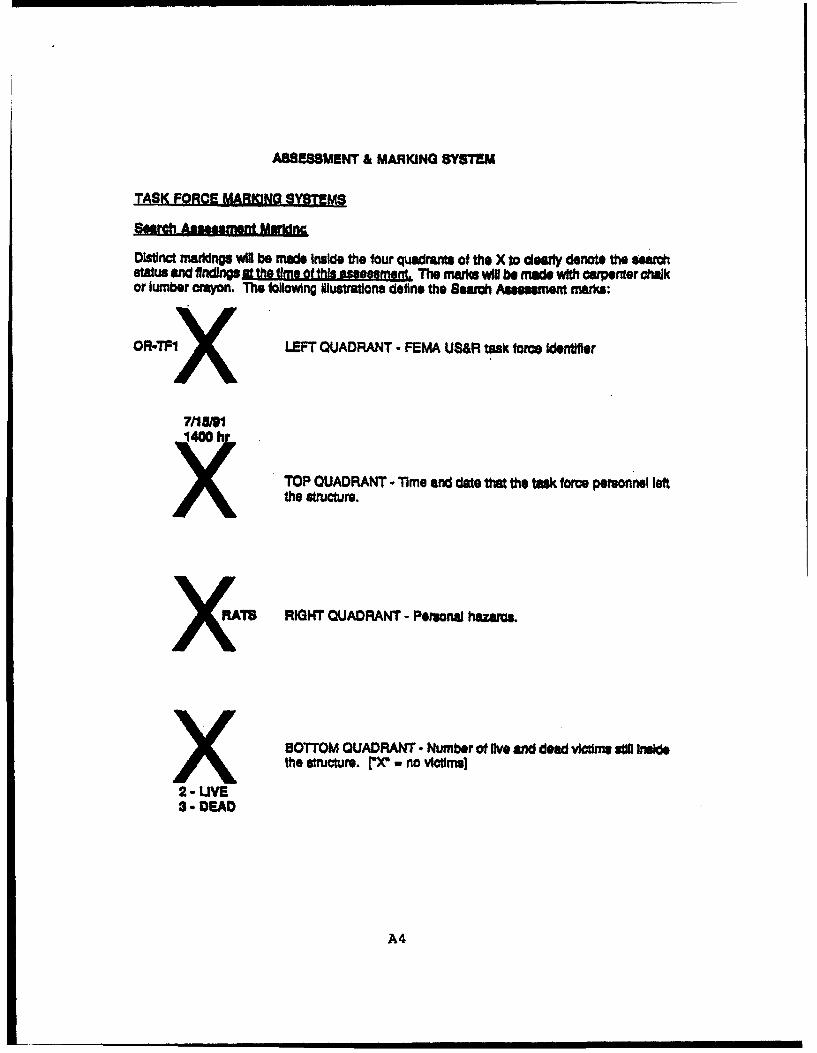
Distinct markings wig be made Inside the four quadrants of the X to ceuwly denote the searchsta and finding st the ime of thlinsmwMgr.' The marks wil be made with carpenter chalkor lumber crayon. The following Illustrattions defilne the Beach Assessment marks:
OR-TPIX LEFT QUADRANT- FEMA US&R task force Wder
X/1 )1TOP QUADRANT -Time and date that the task force personnel leftthe structure,
ATO RIGHT QUADRANT - Personal hazarcs.
X BOTTOM QUADRANT - Number of lve and dead victims stll Insidethe structure. 'X" - no vctims]
2 - UVE3 - DEAD
A4

APPENDIX B
STOLS MODEL 91 ELECTRONIC COMPONENTS
BI
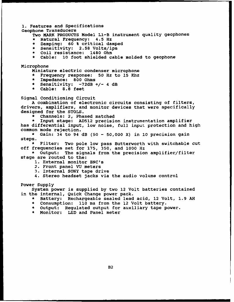
1. Features and SpecificationsGeophone Transducers
Two MARK PRODUCTS Model LI-B instrument quality geophones* Natural Frequency: 4.5 Hz* Damping: 60 % critical damped* Sensitivity: 2.58 Volts/ips* Coil resistance: 1480 Ohm* Cable: 10 foot shielded cable molded to geophone
MicrophoneMiniature electric condenser microphone* Frequency response: 50 Hz to 15 Khz* Impedance: 800 Ohms* Sensitivity: -72dB +/- 4 dB* Cable: 8.8 feet
Signal Conditioning CircuitA combination of electronic circuits consisting of filters,
drivers, amplifiers, and monitor devices that were specificallydesigned for the STOLS.
* Channels: 2, Phased matched* Input stage: AD512 precision instrumentation amplifier
has differential input, low noise, full input protection and highcommon mode rejection.
* Gain: 34 to 94 dB (50 - 50,000 X) in 10 precision gainsteps.
* Filter: Two pole low pass Butterworth with switchable cutoff frequencies set for 175, 350, and 1000 Hz
* Output: The signals from the precision amplifier/filterstage are routed to the:
1. External monitor BNC's2. Front panel VU meters3. Internal SONY tape drive4. Stereo headset jacks via the audio volume control
Power SupplySystem power is supplied by two 12 Volt batteries contained
in the internal, Quick Change power pack.* Battery: Rechargeable sealed lead acid, 12 Volt, 1.9 AH* Consumption: 110 ma from the 12 Volt battery.* Output: Regulated output for auxiliary tape power.* Monitor: LED and Panel meter
B2

Recorder* SONY Model WM-D6C stereo professional cassette recorder* Tape Head: 4-track, 2 channel* Speed Control: Quartz Lock Servo* Filter: Dolby B & C* Line: Output and input* Monitor: LED level meter* Power: 6 Volts, 4 AA dry cells* Frequency Response: 30 Hz to 10 KHz
CaseDeep drawn GUARDIAN aluminum suitcase functions as both a
transit case and instrument housing."* Size: 18.22" X 13.14" X 6.00""* Weight: 32 lbs. fully loaded"* Lock: 3 digit Combination
Accessories* Two Quick Change power packs* Two quality stereo headsets* Two transducer extension cables (20 feet each)* XENOTRONIX battery charger* Two each, Brass Weights and Spike geophone couplers* Two geophone shorting plugs to protect the geophones
during transit* Tape Recorder Adapter
B3
4"7
C AlL R Cc C
vu CO vu 4-0)
PT W 27 0Z7 04
G W CwPT 051u
24 RG 0 0
Wo CI Un + RG $0 44CO U n÷V •R 5
23 -9V It 23
22 xw 21 "; -C13 Cie e1 l
1c I"' a t Czo
017 17 CS 0
-- +4
ISc is 38 0- 1
43 39 E9-5
L 4e 30 3v cis
41 4o 3I
R(S - i I CIO PG P:l- V2 4P.
H L S +- +VE s H L0u
+9 Mi+ I M+
B4

LM
Ono4a
Mom-4
B5p
5-
loi
ISS
' 4 t; t)
B36
0••i i
i
APPENDIX C
OPERATORS CHECKLIST AND TROUBLE SHOOTING
Cl

TROUBLESHOOTING THE STOLS
1.0 Operators can expect few problems from the STOLS as long asthe equipment is operated properly and handled carefully. Sinceunexpected problems can occur, users must be cognizant of basictroubleshooting techniques.
1.1 Equipment problems can be categorized into four basic
groups:
A. Operator Problems
Operator problems occur when the STOLS is incorrectly set upor operates improperly. Even the most experiencedoperators must be ever vigilant for these type ofproblems.
Operator errors can only be reduced with adequate trainingand a good understanding of the STOLS capabilities andlimitations.
Troubleshooters should first eliminate the possibility ofoperator errors before they proceed with an investigationof hardware problems.
B. Mechanical Problems
Since mechanical problems are often difficult if notimpossible to repair in the field, they must be avoided.
The STOLS must be properly packaged for shipment and handledcarefully while in use. The STOLS suitcase was not designedto be shipped or checked as baggage without additionalprotective packing.
The geophones are the most fragile part of the STOLS. Theymust be handled with great care; broken geophon.s can not berepaired in the field.
C. Power Problems
Separate batteries are required to operate the STOLSamplifiers, tape recorder and microphone. A low or badbattery can cause a variety of confusing symptoms. A checkof the STOLS battery should be the first operational andtroubleshooting step.
C2
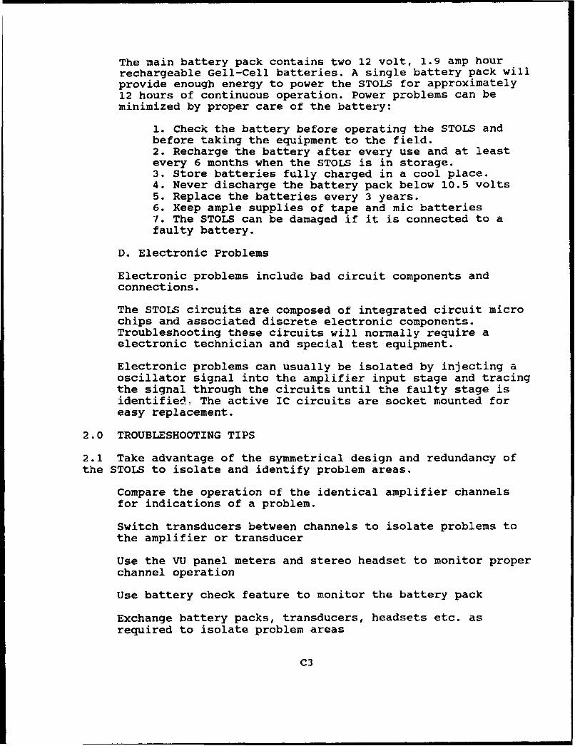
The main battery pack contains two 12 volt, 1.9 amp hourrechargeable Gell-Cell batteries. A single battery pack willprovide enough energy to power the STOLS for approximately12 hours of continuous operation. Power problems can beminimized by proper care of the battery:
1. Check the battery before operating the STOLS andbefore taking the equipment to the field.2. Recharge the battery after every use and at leastevery 6 months when the STOLS is in storage.3. Store batteries fully charged in a cool place.4. Never discharge the battery pack below 10.5 volts5. Replace the batteries every 3 years.6. Keep ample supplies of tape and mic batteries7. The STOLS can be damaged if it is connected to afaulty battery.
D. Electronic Problems
Electronic problems include bad circuit components andconnections.
The STOLS circuits are composed of integrated circuit microchips and associated discrete electronic components.Troubleshooting these circuits will normally require aelectronic technician and special test equipment.
Electronic problems can usually be isolated by injecting aoscillator signal into the amplifier input stage and tracingthe signal through the circuits until the faulty stage isidentified, The active IC circuits are socket mounted foreasy replacement.
2.0 TROUBLESHOOTING TIPS
2.1 Take advantage of the symmetrical design and redundancy ofthe STOLS to isolate and identify problem areas.
Compare the operation of the identical amplifier channelsfor indications of a problem.
Switch transducers between channels to isolate problems tothe amplifier or transducer
Use the VU panel meters and stereo headset to monitor proper
channel operation
Use battery check feature to monitor the battery pack
Exchange battery packs, transducers, headsets etc. asrequired to isolate problem areas
C3
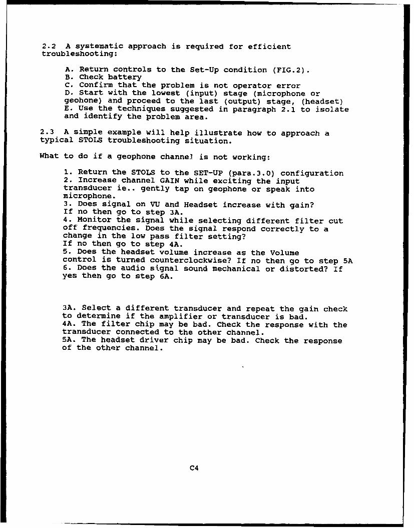
2.2 A systematic approach is required for efficienttroubleshooting:
A. Return controls to the Set-Up condition (FIG.2).B. Check batteryC. Confirm that the problem is not operator errorD. Start with the lowest (input) stage (microphone orgeohone) and proceed to the last (output) stage, (headset)E. Use the techniques suggested in paragraph 2.1 to isolateand identify the problem area.
2.3 A simple example will help illustrate how to approach atypical STOLS troubleshooting situation.
What to do if a geophone channel is not working:
1. Return the STOLS to the SET-UP (para.3.0) configuration2. Increase channel GAIN while exciting the inputtransducer ie.. gently tap on geophone or speak intomicrophone.3. Does signal on VU and Headset increase with gain?If no then go to step 3A.4. Monitor the signal while selecting different filter cutoff frequencies. Does the signal respond correctly to achange in the low pass filter setting?If no then go to step 4A.5. Does the headset volume increase as the Volumecontrol is turned counterclockwise? If no then go to step 5A6. Does the audio signal sound mechanical or distorted? Ifyes then go to step 6A.
3A. Select a different transducer and repeat the gain checkto determine if the amplifier or transducer is bad.4A. The filter chip may be bad. Check the response with thetransducer connected to the other channel.5A. The headset driver chip may be bad. Check the responseof the other channel.
C4
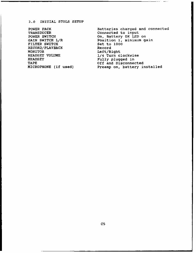
3.0 INITIAL STOLS SETUP
POWER PACK Batteries charged and connectedTRANSDUCER Connected to inputPOWER SWITCH On, Battery OK LED onGAIN SWITCH L/R Position 1, minimum gainFILTER SWITCH Set to 1000RECORD/PLAYBACK RecordMONITOR Left/RightHEADSET VOLUME 1/4 Turn clockwiseHEADSET Fully plugged inTAPE Off and DisconnectedMICROPHONE (if used) Preamp on, battery installed
C5
form Approved
REPORT DOCUMENTATION PAGE oMF No oApp-roedPi ,4c reo•nnq pur.ct to, m t oarcJimon of information 00 etimat"O to a. rige I Nosrpet tt . the t0f r " .ntf o' Se4'ttttq * Qihto xr- -
gate,,q ad ',hth~ g tedtanted ar~td4ctrpvflq A~ th WI',A f ed COrh I legal5t~d-49O thot bvde es~t~rhte rof ot hr :wo orvco~llea*Of of 1nofMtor i~tO, ,nc~k A~ sugg tiOn- for e ;au(tin thl%* o dr•,• to wltshingloh 4*&J40t•aart•r% W,ý,ce, Ovel%'orle for ltfor•-allon~ Ci~petatlCo^ ,4r~ eito. t,, is• ArJtwir'o"
Oaen'4 Hgtwav. SuIte 1204 AZlttot. VA 22102-4302 and t• the O",<e o •a-agen• t nid Sb get..Oqc Pa Retoucli0n P 0• ole (014-0tS6) w. •h.ngtor. OC 2050)
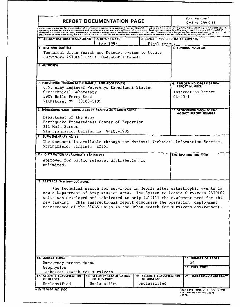
1. AGENCY USE ONLY (Leave blank) 2. REPORT DATE 3. REPORT , Y. -fJi DATES COVERED
May 1993 Final re~rt4. TITLE AND SUBTITLE S. FUNDING NL7.4ABERS
Technical Urban Search and Rescue, System to LocateSurvivors (STOLS) Units, Operator's Manual
6. AUTHOR(S)
7. PERFORMING ORGANIZATION NAME(S) AND ADODRESS(ES) 8. PERFORMING ORGANIZATION
U.S. Army Engineer Waterways Experiment Station REPORT NUMBER
Geotechnical Laboratory Instruction Report3909 Halls Ferry Road GL-93-1Vicksburg, MS 39180-r,199
9. SPONSORING /MONITORING AGENCY NAME(S) AND ADDRESS(ES) 10. SPONSORING/ MONITORING
AGENCY REPORT NUMBER
Department of the ArmyEarthquake Preparedness Center of Expertise211 Main StreetSan Francisco, California 94105-1905
11. SUPPLEMENTARY NOTES
The document is available through the National Technical Information Service,Springfield, Virginia 22161
12a. DISTRIBUTION /AVAILABILITY STATEMENT 12b. DISTRIBUTION CODE
Approved for public release; distribution isunlimited.
13. ABSTRACT (Maximum jO0 words)
The technical search for survivors in debris after catastrophic events isnow a Department of Army mission area. The System to Locate Survivors (STOLS)units was developed and fabricated to help fulfill the equipment need for thisnew tasking. This instructional report discusses the operation, deploymentmaintenance of the STOLS units in the urban search for survivors environment.
"14. SUBJECT TERMS 15. NUMBER OF PAGES
Emergency preparedness 54Geophysics 16. PRICE CODE
Technical search for survivors17. SECURITY CLASSIFICATION 18. SECURITY CLASSIFICATION 19. SECURITY CLASSIFICATION 20. LIMITATION OF ABSTRACT
OF REPORT OF THIS PAGE OF ABSTRACT
Unclassified Unclassified Unclassified
NSN 7540.01-280-5500 Standard Form 298 (Rev 2-89)0 by14 2 ANY Swo Zit