technical vibration characteristics report of oh-58a
TRANSCRIPT

AVSCOM Technical Report 86-C-42
April 1987
. , . . .
I . ,
Vibration Characteristics of OH-58A Helicopter Main Rotor Transmission
David G. Lelvicki and John J. Coy

NASA Tech n ica I Paper 2705
AVSCOM Technical Report 86-C-42
1987
iiatlonal Aeroriaulics and Space Administration
Scientific and Technical information Branch
Vibration Criaracteristics of OH-58A Helicopter Main Rotor Transmission
David G. Lewicki and John J. Coy Propulsion Directorate
Lewis Research Center Cleveland, Ohio
USAAR TA-A VSCOM

Summary Experimental vibration tests were performed on the OH-58A
helicopter main rotor transmission. The tests were conducted in the 500-hp helicopter transmission test stand at NASA Lewis. Seven accelerometers were mounted at various locations on the transmission housing. The testing consisted of a matrix of torque and speed conditions covering transmission input torques of 176 to 352 N-m (1559 to 3119 lb-in.) and trans- mission input speeds of 3000 to 6000 rpm. Accelerometer signals were analyzed by using Fourier spectra, power spectral density functions, and averaging techniques.
The Fourier spectra analysis showed vibration amplitude peaks occurring at the spiral bevel and planetary gear mesh harmonics. The highest magnitude of vibration was at the spiral bevel gear meshing frequency. Harmonic sideband frequencies for both the spiral bevel mesh and the planetary mesh occurred at multiples of the planet passing frequency. Accelerometer root-mean-square (rms) average vibration levels were also determined. Transmission speed had a significant effect on rms vibration levels, but transmission torque had a small effect. At the same speed and torque conditions, measured vibration levels were different at different locations but the same for different measurement directions at the same location. Spiral bevel mesh and planetary mesh vibration contributions were determined by using power spectral density functions. There was, however, no trend as to the effect of torque or speed on spiral bevel mesh or planetary mesh vibration contributions as a percentage of total vibration.
Introduction Helicopter noise and vibration are important topics because
of health and environment concerns, passenger comfort, and pilot efficiency. Both external and internal noise create concern. External noise is due to the rotor blades and the engine inlet and exhaust; internal noise is attributed to transmission vibration, and in particular, to the gears. The standard approach to quieting the helicopter interior is to add cabin acoustic material. The corresponding weight penalty opposes the goal of ever-increasing power-to-weight ratios for helicopter drive systems.
As power increases so does the weight penalty associated with cabin soundproofing materials (ref. 1). This has led to an effort to reduce noise and vibration at their origin.
Transmissions are the main source of noise in today’s helicopter interiors, with the noise originating from the gear mesh (ref. 2). Gear tooth or shaft deflections, gear tooth profile errors, or gear or bearing misalignments can lead to dynamic loads, vibration, and noise (refs. 3 and 4). In addition to the annoyance of transmission noise, lack of vibration control near resonant frequencies can lead to damaging transmission failures (refs. 5 and 6).
Vibration and temperature tests were performed on the main rotor transmission for the OH-58A U.S. Army light observation helicopter (ref. 7). Spectrum analyses showed the dominant sources of vibration to be the spiral bevel gear mesh and the planetary gear mesh. For normal operating conditions the highest vibration amplitude occurred at the spiral bevel meshing frequency. Transmission vibration tests were also performed on larger helicopters (refs. 8 and 9). Quite high vibration levels are associated with these transmissions, and methods to reduce noise and vibration are being developed (refs. 1, 10, and 11).
The objective of the present study was to measure vibration data for the OH-58A main rotor helicopter transmission. The results can serve as baseline data for comparison with measured results from future technological improvements in component and total system design, manufacturing techniques, or materials. Experimental vibration tests were performed on the OH-58A transmission over a range of torque and speed conditions at NASA Lewis. Vibration results are presented as Fourier spectra and average accelerations.
Apparatus OH-58A Main Rotor Transmission
The OH-58A is a single-engine, land-based light observation helicopter. The helicopter serves both military (OH-58A Kiowa) and commercial (Bell Model 206 Jet Ranger) needs. The OH-58A main rotor transmission (fig. 1) is rated for use at an engine output of 210-kW (270-hp) continuous power at 6180 rpm and 236 kW (317 hp) for 5 min at takeoff (ref. 7). The transmission is a two-stage reduction gearbox. For the first stage the input shaft drives a 19-tooth spiral bevel pinion gear, which meshes with a 71-tooth gear. The bevel pinion shaft is mounted on triplex ball bearings and one roller bearing. The bevel gear shaft is mounted on duplex ball bearings and one roller bearing.
1

t
Figure 1 .-0H-58A helicopter main rotor transmission.

A planetary mesh provides the second reduction stage. The bevel gear shaft is splined to a sun gear shaft. The 27-tooth sun gear drives three %-tooth planet gears. The planet gears mesh with a 99-tooth fixed ring gear, which is splined to the top case. The planet gears are mounted on double-row spherical roller bearings; the bearings are attached to the planet carrier. Power is taken out through the planet carrier, which is splined to the mast output shaft. The output shaft is supported by a ball bearing and a roller bearing. The overall reduction ratio of the main power train is 17.44: 1.
The 71-tooth bevel gear also drives a 27-tooth accessory gear. The accessory gear runs an oil pump, and lubrication is supplied through jets located in the top case.
NASA Lewis Test Stand
Vibration tests were performed in the NASA Lewis 500-hp helicopter transmission test stand (fig. 2). The test stand oper- ates on the “four square” or torque-regenerative principle. Mechanical power is recirculated through a closed loop of gears and shafting, one of which is the test transmission. In the test stand the output of the test transmission is attached to the bevel gearbox. The output shaft of the bevel gearbox passes through a hollow shaft in the closing-end gearbox and is connected to the differential gearbox. The output of the differential is attached to the hollow shaft in the closing-end gearbox. The output of the closing-end gearbox is connected to the input of the test transmission, thereby closing the loop.
A 149-kW (200-hp) direct-current (dc) motor powers the test stand and controls the speed. The motor output is attached to the closing-end gearbox. Only losses due to friction are replenished by the motor since power is recirculated around the loop.
An 1 1-kW (15-hp) dc motor provides the torque in the closed loop. The motor drives a magnetic particle clutch. The clutch output does not turn but exerts a torque through a speed reducer gearbox and a chain drive to a large sprocket on the differential gearbox. The torque on the sprocket puts a torque in the differential gearbox, which in turn, provides the torque in the closed loop. The magnitude of torque in the loop is adjusted by changing the electric field strength of the magnetic particle clutch.
The test transmission input and output shafts are equipped with speed sensors, torquemeters, and sliprings. Test trans- mission lubrication is supplied by an internal oil pump. The transmission oil can be cooled by a flight hardware aidoil cooler mounted on the transmission (with forced air provided to the cooler) or by an external oil/water heat exchanger. An external oil-pumping system located in the basement below the test stand room is aiso avaiiabie for the lest transmission.
The 149-kW (200-hp) motor is equipped with a speed sensor and a torquemeter. The magnetic particle clutch is equipped with speed sensors on the input and output shafts and with thermocouples. A facility oil-pumping and cooling system
lubricates the differential gearbox, the closing-end gearbox, and the bevel gearbox. The facility gearboxes are also equipped with accelerometers and thermocouples for health monitoring.
Instrumentation and Testing Procedure
Seven piezoelectric accelerometers were mounted on the OH-58A transmission housing (table I, fig. 3). The accelerometers were located on the right and left trunnion mounts, the input bevel pinion gear housing, and the ring gear
TABLE L-OH-58A TRANSMISSION ACCELEROMETER LOCATIONS
[See also fig. 3.1
Accelerometer Location
Ring gear housing Right trunnion mount Right trunnion mount Right trunnion mount Input bevel gear housing Input bevel gear housing Left trunnion mount
Direction
45” Transverse-longitudinal Transverse
Longitudinal Vertical
Transverse Vertical Vertical
1 Transverse Left trunnion mount-
Right trunnion mount-’,’
I n p u t
OuQut t
1 -I .ongitudinal
Vertical
-Longitudinal I
Figure 3 .-Accelerometer locations on OH-58A transmission.
3
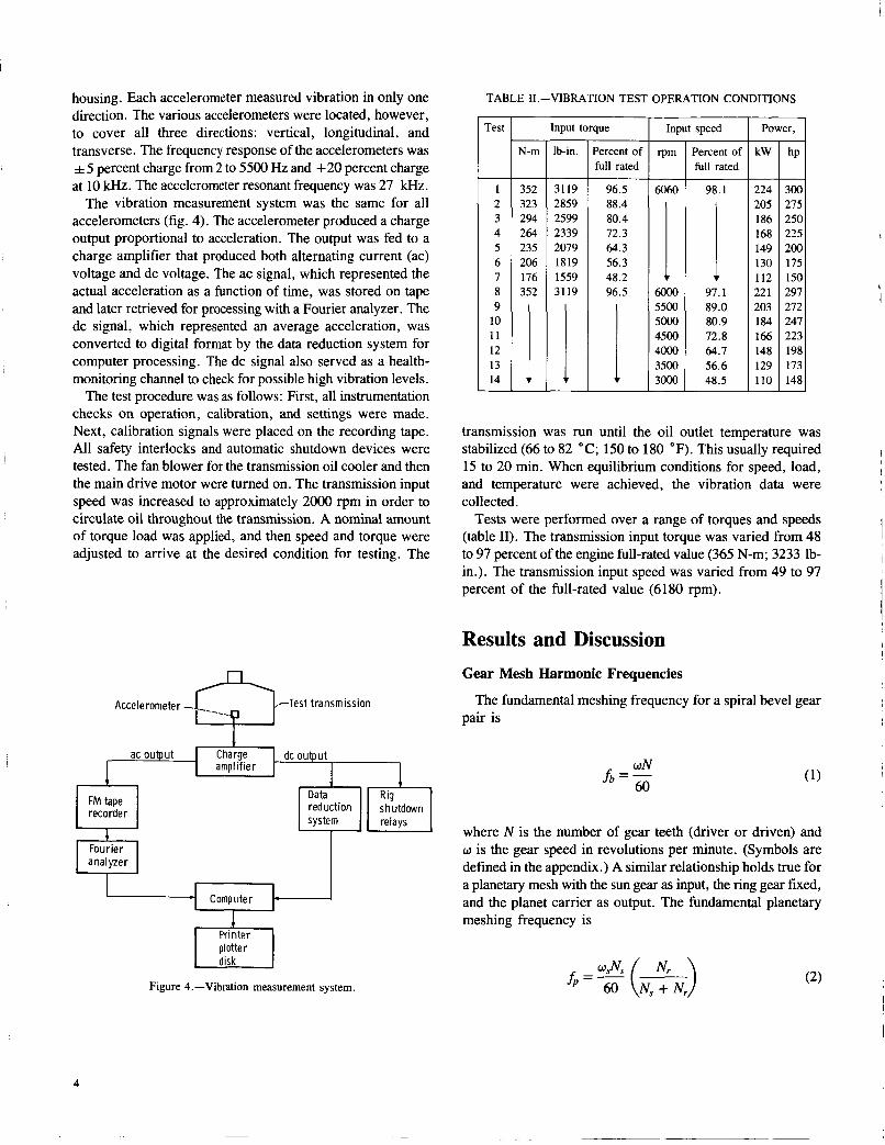
housing. Each accelerometer measured vibration in only one direction. The various accelerometers were located, however, to cover all three directions: vertical, longitudinal, and transverse. The frequency response of the accelerometers was + 5 percent charge from 2 to 5500 Hz and +20 percent charge at 10 kHz. The accelerometer resonant frequency was 27 kHz.
The vibration measurement system was the same for all accelerometers (fig. 4). The accelerometer produced a charge output proportional to acceleration. The output was fed to a charge amplifier that produced both alternating current (ac) voltage and dc voltage. The ac signal, which represented the actual acceleration as a function of time, was stored on tape and later retrieved for processing with a Fourier analyzer. The dc signal, which represented an average acceleration, was converted to digital format by the data reduction system for computer processing. The dc signal also served as a health- monitoring channel to check for possible high vibration levels.
The test procedure was as follows: First, all instrumentation checks on operation, calibration, and settings were made. Next, calibration signals were placed on the recording tape. All safety interlocks and automatic shutdown devices were tested. The fan blower for the transmission oil cooler and then the main drive motor were turned on. The transmission input speed was increased to approximately 2000 rpm in order to circulate oil throughout the transmission. A nominal amount of torque load was applied, and then speed and torque were adjusted to arrive at the desired condition for testing. The
Accelerometer - f i - T e s t t ransmission
dc output
FM tape recorder
Printer plotter
Figure 4.-Vibration measurement system.
TABLE 11.-VIBRATION TEST OPERATION CONDITIONS - Test
_.
1 2 3 4 5 6 7 8 9
10 11 12 13 14 -
N-m
352 323 294 264 235 206 176 352
Input torque
lb-in.
- 3119 2859 2599 2339 2079 1819 1559 3119
Percent of full rated
96.5 88.4 80.4 72.3 64.3 56.3 48.2 96.5
1
Input speed
6060
1 6Ooo 5500 5000 4500 4000 3500 3000 __
Percent of full rated
98.1
! 97.1 89.0 80.9 72.8 64.7 56.6 48.5
Power, I - kW
- 224 205 186 168 149 130 112 22 1 203 184 166 148 129 110 -
272 247 223
173 148
transmission was run until the oil outlet temperature was stabilized (66 to 82 OC; 150 to 180 OF). This usually required 15 to 20 min. When equilibrium conditions for speed, load, and temperature were achieved, the vibration data were collected.
Tests were performed over a range of torques and speeds (table 11). The transmission input torque was varied from 48 to 97 percent of the engine full-rated value (365 N-m; 3233 lb- in.). The transmission input speed was varied from 49 to 97 percent of the full-rated value (6180 rpm).
Results and Discussion Gear Mesh Harmonic Frequencies
pair is The fundamental meshing frequency for a spiral bevel gear
where N is the number of gear teeth (driver or driven) and w is the gear speed in revolutions per minute. (Symbols are defined in the appendix.) A similar relationship holds true for a planetary mesh with the sun gear as input, the ring gear fixed, and the planet carrier as output. The fundamental planetary meshing frequency is
A

~~~~ ~~~~
TABLE III.-OH-%A TRANSMISSION SPIRAL BEVEL MESH AND
PLANETARY MESH HARMONIC FREQUENCIES
[Input speed, 6060 rpm.]
Harmonic
Fundamental 2nd 3rd 4th 5th 6th 7th 8th 9th 10th 11th 12th 13th 14th 15th 16th 17th
Spiral bevel Planetary _ _ _ _ ~ mesh I mesh
Harmonic frequency, Hz
1919 3838 5757 7676 9595
573 1147 1720 2294 2867 3440 4014 4587 5160 5734 6307 6881 7454 8027 8601 9174 9748
where N, is the number of sun gear teeth, N , is the number of ring gear teeth, and w, is the sun gear speed in revolutions per minute. The term in parentheses relates the sun gear rotation to a fixed planet carrier system. This is needed to account for planet gear relative rotation. Note that the meshing frequency of equation (2) applies for a sun gear meshing with a planet gear as well as for a planet gear meshing with a ring gear.
Harmonic frequencies are defined as integer multiples of the fundamental frequency. The second harmonic is two times the fundamental frequency, the third harmonic is three times the fundamental frequency, and so on. For the OH-58A transmission the spiral bevel mesh has 5 harmonics and the planetary mesh has 17 harmonics in the 0- to 10-kHz range at an input speed of 6060 rpm (table 111).
Fourier Spectra
The typical accelerometer response as a function of time was quite irregular (fig. 5). The response was converted from the time domain to the frequency domain by using a Fourier transformation. Thus the erratic vibration was broken down into its harmonic components.
Accelerometer acceleration x ( t ) , a continuous function of time r (fig. 6(a)), can be approximated by xi through use of a discrete number of points (fig. 6(b)), where
6o r 30
P) 0.
0 10 20 30 40 Time. msec
-60
Figure 5.-Time trace of accelerometer 1 (ring gear housing).
t i
fk
(a) Continuous function-time domain. (b) Discrete function-time domain.
(c) Discrete Fourier transform-frequency domain
Figure 6.-Discrete Fourier transform.
5

Tis the time period, and N is the number of intervals. The bandwidth B is defined as
1 B = - T
Assuming xi is periodic with T, the real portion of the discrete Fourier transform (DFT) from reference 12 is
and the imaginary portion of the DFT is
where k is an integer from 0 to N - 1. The magnitude factor X ’ ( f k ) is defined as
X‘( f,) = (a; + b:)1’2
and is a function of frequency fk, where
k f”=5 (9)
as shown in figure 6(c). The data signals were conditioned to avoid aliasing such that
where f, was the maximum frequency component in x ( t ) (aliasing is the production of nonexistent frequency compo- nents in the DFT). Also, k ranged from 0 to K , where
6
The OH-58A accelerometer ac outputs were retrieved from tape and fed to a spectrum analyzer. The spectrum analyzer performed a fast Fourier transform (FFT). The FFT is an efficient computer algorithm for calculating discrete Fourier transforms (ref. 12). The analyzer output was a magnitude factor X ( fk), where
The analyzer was set forfK = 10 kHz. Internally the analyzer used N = 1024 intervals, and for fK = 10 lcHz the analyzer had a time period of T = 0.04 sec. This produced a bandwidth B of 25 Hz, a time interval between samples A of 3.91 X sec, and K = 400 intervals for the frequency domain. The analyzer was also set for Hanning windowing. The windowing function modified the acceleration time waveform xi by weighting the waveform so that the beginning and ending points reduced to zero. The weighting reduced the distortion caused by finite record samples of the FFT process and nonperiodic acceleration waveforms.
The analyzer also performed an rms averaging technique on the magnitude factor to smooth the signal variations with time. At each frequency the average magnitude factor was composed of 50 readings, where
Accelerometer 1 (on the ring gear housing) produced the highest levels of vibration. From the Fourier transformation the dominant vibration sources were the spiral bevel mesh and the planetary mesh (fig. 7(a)).Vibration amplitude spikes occurred at the spiral bevel mesh and planetary mesh harmonic frequencies. The highest vibration amplitude was at the spiral bevel fundamental meshing frequency.
The vibration spectra of accelerometers 2 to 4 (on the right trunnion mount, figs. 7(b) to (d)) were similar in trend to that of accelerometer 1. Spikes occurred at the spiral bevel mesh and planetary mesh harmonics, and the highest amplitude was at the spiral bevel fundamental frequency. Note that figures 7(b) to (d) are rather similar, implying that the measured vibration was not significantly affected by the measurement direction.
The vibration spectra of accelerometers 5 and 6 (on the input bevel gear housing, figs. 7(e) and (0) had lower vibration levels than the other spectra. The spiral bevel harmonics were the dominant vibration sources, but the large amplitude at the spiral bevel fundamental frequency did not occur. Acceler- ometer 7 (on the left trunnion mount, fig. 7(g)) had trends

6
5
4
?
2
1 v)
E VI
m
xE i
_m
0 V c
al 4 -
2
-J
4.- .- c m
3 )
0
IC)
0 3 -
Mesh harmonics 0 Spiral bevel v Planetary
t 0
i l 0 I a
0 B
0 2 4 6 8 10
VI
c k - E U V I 1 - c -m
3 al n
C cn c .-
2 4 6 8 10 2 0 - Frequency, kHz
(a) Accelerometer 1 (ring gear housing). (c) Accelerometer 3 (right trunnion mount, longitudinal). (e) Accelerometer 5 (input bevel gear housing, transverse).
(b) Accelerometer 2 (right trunnion mount, transverse). (d) Accelerometer 4 (right trunnion mount, vertical). (f) Accelerometer 6 (input bevel gear housing, vertical).
(g) Accelerometer 7 (left trunnion mount, vertical).
Figure 7.-Vibration spectra. Input speed, 6060 rpm; input torque, 352 N-m (3119 lb-in.).
7

similar to that of the right trunnion mount. The vibration levels, however, were only about half those of the right trunnion mount.
Gear vibration spectra may possess sidebands about the fundamental and harmonic frequencies (ref. 13). Sidebands result from amplitude modulation and frequency modulation. Amplitude modulation occurs when excitation force amplitudes vary with time, such as for eccentric gears. Frequency modula- tion results when mesh frequencies change with time, such as for gears with tooth spacing errors or torsional vibration. Sidebands usually occur at frequencies of
h i d e = f m * nfS (14)
where f m is a fundamental or harmonic meshing frequency, fs is the gear shaft frequency (driver or driven), and n is an integer (1,2,3 ,... ).
For planetary meshes sidebands may also occur at multiples of the planet passing frequency, where
h i d e = f m n f p (15)
and P is the number of planet gears. Equation (16) is valid for a fixed-ring planetary with the sun gear as input and the planet carrier as output.
The OH-58A planet passing frequency at 6060-rpm input speed is 17 Hz. The sidebands for the spiral bevel mesh and the planetary mesh occurred at multiples of the planet passing frequency (fig. 8). Very few sidebands correlating to amplitude or frequency modulation were found (using a linear scale on the Fourier transformation). This implies high-quality gears and high-accuracy installation. Note that the sideband frequencies were determined by using a zoom feature of the spectrum analyzer. The zoom feature basically increases the time period of the time domain signal (by sampling more points), and this, in turn decreases the bandwidth. In deter- mining the sideband frequencies of figure 8, B = 0.625 Hz was used. Also note that rms averaging was not used.
Average Vibration
The rms average acceleration on the time trace is defined as
8
5
4
VI
m - Y z 3 i 0
" - L
m 'c)
L ._ z z 2
1
O1
I / / I I/ I
3 18M) Frequency, Hz
Figure 8.-Zoom vibration spectrum of accelerometer 1 (ring gear housing, fig. 6(a)). Input speed, 6060 rpm; input torque, 352 N-m (3119 lb-in.); planet passing frequency, 17 Hz.
For a time trace of length T the rms acceleration can be approximated by considering discrete points where
and I is the total number of points. The OH-58A acceleration time traces (fig. 5 as an example)
were retrieved from tape, fed to the spectrum analyzer, and routed to a computer for rms average calculations. The time interval between samples A and the total number of points I were varied in hopes of optimizing the data collection. The analyzer had a finite number of time intervals available (A = 3.906,7.813, 15.625, 19.531 psec, etc.). Atimeinterval of 15.625 psec was chosen. For A > 15.625 psec the digital approximations failed to encompass all the time trace peaks. This led to a lower-than-actual rms calculation, regardless of the total number of points taken. For A < 15.625 psec the rms calculations required more data points for convergence than calculations with A = 15.625 psec.
Data were collected in sets of 3 1 744 points (the maximum allowed for the analyzer-computer software). The rms average based on the cumulation of five sets compared with the rms average based on the cumulation of four sets usually produced

Accelerometer 0 1 0 2 n 3 0 4 n 5
40 50 60 70 80 90 100 Inpu t torque, percent of full rated
Figure 9.-Effect of torque on vibration.
an error of less than 1 percent. Thus for each test condition of table II five sets for each accelerometer were accumulated. Five sets of 31 744 points each and A = 15.625 psec gave total points I of 158 720 and a total time period T of 2.48 sec.
Torque had a small effect on vibration (fig. 9). For all accelerometers the vibration increased with torque for torques from 50 to 65 percent of full rated. Above 65 percent the vibration was fairly constant. Accelerometer 1 (on the ring gear housing) was the only exception. For this accelerometer vibration increased with torque for the full range of torques tested. Note that accelerometers located in the same locations but measuring in different directions (2 to 4 on the right trunnion mount; 5 and 6 on the input bevel gear housing) had similar results. This implies that measurement direction had a small effect on measured vibration. Also, the measured vibration levels were different depending on measurement location as some locations (such as the right trunnion mount, accelerometers 2 to 4) had higher vibration levels than others (such as the left trunnion mount, accelerometer 7). Note that the vibration levels of accelerometers 4 and 7 are different even though the mounting geometry is symmetric. One explanation is the nonsymmetric loading that the transmission sees.
Speed significantly affected vibration (fig. 10). Vibration continued to increase with speed for accelerometer 1 (the ring gear housing, fig. !O(a)). For d l other accelerometerb vibration increased with speed until a resonant point was reached (figs.
12
10
8
6
4
2
VI
E o VI
Accelerometer - 0 1 0 2
c-
E 0 .- c
El
W U U m
El L
-
m 3 a c m
? 2 w
4
2 :I (b)
0
Cl
50 60 70 80 90 100 input speed, percent of full rated
(a) Accelerometer 1 . (b) Accelerometers 2, 3, 4, and 7
(c) Accelerometers 5 and 6.
Figure 10.-Effect of speed on vibration.
10(b) and (c)). Then it usually decreased slightly as speed increased above the resonance. In addition, the measured resonant speed differed with measurement location and direction.
9
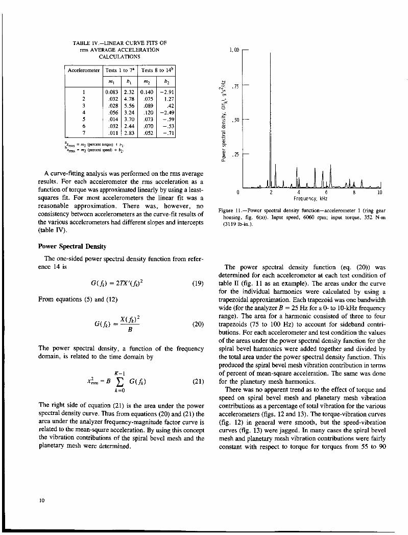
TABLE 1V.-LINEAR CURVE FITS OF rms AVERAGE ACCELERATION
CALCULATIONS
Accelerometer I Tests 1 to 7a I Tests 8 to 14b I ml
0.083 ,032 ,028 .056 .014 ,032 ,011
- -2.91
-2.49 - .59 - .53 -.71
arms = m l (percent torque) + b,. bxms = m2 (percent speed) + b.
A curve-fitting analysis was performed on the rms average results. For each accelerometer the rms acceleration as a function of torque was approximated linearly by using a least- squares fit. For most accelerometers the linear fit was a reasonable approximation. There was, however, no consistency between accelerometers as the curve-fit results of the various accelerometers had different slopes and intercepts (table IV).
Power Spectral Density
ence 14 is The one-sided power spectral density function from refer-
From equations (5) and (12)
The power spectral density, a function of the frequency domain, is related to the time domain by
The right side of equation (21) is the area under the power spectral density curve. Thus from equations (20) and (21) the area under the analyzer frequency-magnitude factor curve is related to the mean-square acceleration. By using this concept the vibration contributions of the spiral bevel mesh and the planetary mesh were determined.
1.00
N I &j- .7! v)
m - Y
L - u >; c ._ g .50
E
%
2 .25
al U - c V al
L
a
0 4 c 8 10 Frequency, kHz
Figure 1 1 .-Power spectral density function-accelerometer 1 (ring gear housing, fig. 6(a)). Input speed, 6060 rpm; input torque, 352 N-m (3119 lb-in.).
The power spectral density function (eq. (20)) was determined for each accelerometer at each test condition of table I1 (fig. 1 1 as an example). The areas under the curve for the individual harmonics were calculated by using a trapezoidal approximation. Each trapezoid was one bandwidth wide (for the analyzer B = 25 Hz for a 0- to 10-kHz frequency range). The area for a harmonic consisted of three to four trapezoids (75 to 100 Hz) to account for sideband contri- butions. For each accelerometer and test condition the values of the areas under the power spectral density function for the spiral bevel harmonics were added together and divided by the total area under the power spectral density function. This produced the spiral bevel mesh vibration contribution in terms of percent of mean-square acceleration. The same was done for the planetary mesh harmonics.
There was no apparent trend as to the effect of torque and speed on spiral bevel mesh and planetary mesh vibration contributions as a percentage of total vibration for the various accelerometers (figs. 12 and 13). The torque-vibration curves (fig. 12) in general were smooth, but the speed-vibration curves (fig. 13) were jagged. In many cases the spiral bevel mesh and planetary mesh vibration contributions were fairly constant with respect to torque for torques from 55 to 90
10

50
40
30
- 20 c 2 L 0
10 2 0) n
L 50
u U m
i? 2 40 z c m
30
20
10
Accelerometer 0 1 0 2 a 3 0 4
-
-
-
-
-
(b)
5 6 7
60
50
40
30
20 - c I 0
2 10 2 0) n
Accelerometer - 0 1
0 2 A 3
- 0 4 n 5
lo t (b)
40 50 60 70 80 90 100 0
Input speed, percentof f u l l rated
(a) Spiral bevel mesh. (b) Planetary mesh.
Figure 13.-Effect of speed on vibration contribution.
bevel mesh or the planetary mesh had contributed more to the vibration (figs. 14 and 15). The spiral bevel mesh contributed more than the planetary mesh in some cases (fig. 15@) at 4500 rpm as an example), but the planetary mesh contributed more in other cases (fig. 15(g) at 3000 rpm as an example).
1 1

1
40
20
0 -
c m
Mesh
Spiral bevel
- Planetary
s L I" 4u
20
0 176 206 235 264 294 323 352 176 206 235 264 294 323 352
Input torque, N-m
176 206 235 764 294 323 352 input torque, N-m
(a) Accelerometer 1 (ring gear housing). (b) Accelerometer 2 (right trunnion mount, transverse).
(c) Accelerometer 3 (right trunnion mount, longitudinal) (d) Accelerometer 4 (right trunnion mount, vertical).
(e) Accelerometer 5 (input bevel gear housing, transverse). (f) Accelerometer 6 (input bevel gear housing, vertical).
(9) Accelerometer 7 (left trunnion mount, vertical).
Figure 14.-Effect of torque on spiral bevel mesh and planetary mesh contributions to vibration.
12

60
40
20
- g o - 0 5 60 2
$ 40 e
al n
.- c
al al - ; 20
7 0 E m =
c m ' 60
40
20
0
- IC)
-
- Planetary
pi I m m
3000 3500 4000 4500 5000 5500 6000 Input speed, rpm
" 3000 3500 4000 4500 5M)o 55M) 6000 Input speed, rpm
(a) Accelerometer 1 (ring gear housing). (b) Accelerometer 2 (right trunnion mount, transverse).
(c) Accelerometer 3 (right trunnion mount, longitudinal). (d) accelerometer 4 (right trunnion mount, vertical).
(e) Accelerometer 5 (input bevel gear housing, transverse). (f) Accelerometer 6 (input bevel gear housing, vertical).
(8) Accelerometer 7 (left trunnion mount, vertical).
Figure 15.-Effect of speed on spiral bevel mesh and planetary mesh contributions to vibration.
13

a *
Summary of Results Experimental vibration tests were performed at NASA Lewis
on the OH-58A helicopter main rotor transmission over a range of torques and speeds. Signals from accelerometers located on the transmission housing were analyzed by using Fourier spectra, power spectral density functions, and averaging techniques. The following results were obtained:
1. Transmission speed and vibration measurement location significantly affected measured rms average vibration. As speed increased, vibration generally increased, reached a maximum, and then remained fairly constant. The speed at which the measured maximum vibration occurred depended on accelerometer location.
2. The magnitude of vibration was highest at the spiral bevel gear meshing frequency.
4
3. Most peaks of the Fourier spectra occurred at spiral bevel gear mesh harmonics or at planetary mesh harmonics. Sideband frequencies for both spiral bevel gear harmonics and planetary harmonics occurred at multiples of the planet passing frequency.
4. Transmission torque and vibration measurement direction had a small effect on measured rms average vibration.
5. There was no trend as to the effect of torque or speed on spiral bevel gear mesh or planetary mesh vibration contribu- tions as a percentage of total vibration.
Lewis Research Center National Aeronautics and Space Administration Cleveland, Ohio, January 26, 1987
Appendix-Symbols
discrete Fourier transform term, g's bandwidth, Hz intercepts discrete Fourier transform term, g's spiral bevel mesh fundamental frequency, Hz maximum frequency, Hz k" frequency, Hz fundamental or harmonic frequency, Hz planetary mesh fundamental frequency, Hz planet passing frequency, Hz gear shaft frequency, Hz sideband frequency, Hz one-sided power spectral density function, g's2/Hz number of points i" point j" point number of intervals, frequency domain k" point
m1.m2 slopes N
Nr NS n integer (1,2,3,. . .) P number of planets T time period, sec t time, sec X ( f k ) analyzer magnitude factor, g's X' (fk) discrete Fourier transform magnitude factor, g's Xms(fk) analyzer rms average magnitude factor, g's rms X acceleration, g's (zero to peak) x,, root-mean-square acceleration, g 's rms A time interval between samples, sec W gear speed, rpm WS sun gear speed, rpm
number of gear teeth; or number of intervals, time domain number of ring gear teeth number of sun gear teeth

References
1. Yoerkie, C.A.; and Chory, A.G.: Acoustic Vibration Characteristics of High Contact Ratio Planetary Gears. 40th Annual Forum, American Helicopter Society, 1984, pp. 19-32.
2. Weden, G.J.; and Coy, J.J.: Summary of Drive Train Component Technology in Helicopters. Gears and Power Transmission Systems for Helicopters and Turboprops, AGARD CP-369, AGARD, 1985, pp. 2-1
3. Cornell, R.W.; and Westervelt, W.W.: Dynamic Tooth Loads and Stressing for High Contact Ratio Spur Gears. J. Mech. Des., vol. 100, no. 1, Jan. 1978, pp. 69-76.
4. Mark, W.D.: Gear Noise Excitation. Engine Noise: Excitation, Vibration, and Radiation, R. Hickling and M.M. Kamal, eds., Plenum, 1982, pp. 55-94.
5. Drago, R.J.; and Brown, F.W.: The Analytical and Experimental Evaluation of Resonant Response in High-speed, Lightweight, Highly Loaded Gearing. J. Mech. Des., vol. 103, no. 2, Apr. 1981, pp.
6. El-Bayoumy, L.E.: Identification and Correction of Damaging Resonances in Gear Drives. AGMA P159.05, American Gear Manufacturers Association, 1983.
7. Townsend, D.P.; Coy, J.J.; and Hatvani, B.R.: OH-58 Helicopter Transmission Failure Analysis. NASA TM X-71867, 1976.
to 2-17.
346-356.
8. Mitchell, A.M.; Oswald, F.B.; and Schuller, F.T.: Testing of YUHdlA Helicopter Transmission in NASA Lewis 2240-kW (3000-hp) Facility. NASA TP-2538, 1986.
9. Mitchell, A.M.; Oswald, F.B.; and Coe, H.H.: Testing of UH-60A Helicopter Transmission in NASA Lewis 2240-kW (3000-hp) Facility.
10. Litvin, F.L., et al.: Spiral Bevel and Circular Arc Helical Gears: Tooth Contact Analysis and the Effect of Misalignment on Circular Arc Helical Gears. AIAA Paper 85-1139, July 1985.
11. Litvin, F.L., et al.: Generation of Spiral Bevel Gears With Zero Kinematical Errors and Computer Aided Tooth Contact Analysis. NASA
12. Newland, D.E.: An Introduction to Random Vibrations and Spectral Analysis. Longman Group Limited, London, 1975.
13. Houser, D.R.: Basis for Spectral Analysis. Fifth Turbomechanics Seminar: Spectral Analysis in Machinery Health Monitoring, National Research Council of Canada, 1978, pp. 1-1 to 1-37.
14. Bendat, J.S.; and Piersol, A.G.: Engineering Applications of Correlation and Spectral Analysis. John Wiley & Sons, 1980.
NASA TP-2626, 1986.
TM-87273, 1986.
15

1. Report No.
NASA TP-2705 AVSCOM TR 86-(2-42
7. Author@)
David G. Lewicki and John J. Coy
2. Government Accession No.
-
9. Performing Organization Name and Address
NASA Lewis Research Center and Propulsion Directorate, U. S. Army Aviation Research and Technology Activity-AVSCOM, Cleveland, Ohio 44135
2. Sponsoring Agency Name and Address
National Aeronautics and Space Administration Washington, D.C. 20546 and U.S. Army Aviation Systems Command, St. Louis, Mo. 63120
21. No of pages I 20. Security Classif. (of this page)
3. Recipient's Catalog No.
22. Price'
5. Report Date
A p r i l 1987 6. Performing Organization Code
Unclassified
8. Performing Organization Report No.
E-3368 IO. Work Unit No.
505-6 3- 51
11. Contract or Grant No.
Unclassified 17 A02
13. Type of Report and Period Covered
Technical Paper
14. Sponsoring Agency Code
5. Supplementary Notes
David G. Lewicki and John J. Coy: Propulsion Directorate , USAARTA-AVSCOM.
6. Abstract
Experimental vibration tests covering a range of torque and speed conditions were performed on the OH-58A helicopter main rotor transmission at the NASA Lewis Research Center. Signals from accelerometers !ocated on the transmission housing were analyzed by using Fourier spectra, power spectral density functions, and averaging techniques. Most peaks of the Fourier spectra occurred at the spiral bevel and planetary gear mesh harmonics. The highest level of vibration occurred at the spiral bevel meshing frequency. Transmission speed and vibration measurement location had a significant effect on measured vibration; transmission torque and measurement direc- tion had a small effect.
~~ ~
7. Key Words (Suggested by Author@))
Helicopters; Transmissions; Vibration; Vibration testing; Gears; Fourier spectra; Power spectral density functions
19. Sscurity C!assif. (of this report)
18. Distribution Statement
Unclassified - unlimited STAR Category 37
i
'For sale by the National Technical Information Service, Springfield, Virginia 22161 NASA-Langley, 1987