technical white paper 7, 2017 v. 1.0 initial version of the technical paper je dec 4, 2017 v. 2.0...
TRANSCRIPT


Technical White Paper:
A Decentralized Mobile Mesh Networking Platform Powered by Blockchain Technology and Tokenization
Authors: Dr. Jason Ernst, Dr. Zehua (David) Wang, Saju Abraham, John Lyotier, Chris Jensen, Melissa Quinn, Aldrin D’Souza
Change Log
Date Version Comments/Edits Editor
Sep 7, 2017 V. 1.0 Initial version of the technical paper JE
Dec 4, 2017 V. 2.0 Updated the Token Model, Added Networking Details, Added some basic assumption calculations
JE
Dec 10, 2017 V. 2.0 Updated Legal Statements JL, SO
Dec 13, 2017 V. 3.0 Updated legal statements and global edits MQ JL
Dec 15, 2017 V. 3.1 Minor Edits JL
Dec 18, 2017 V. 3.2 Updates for channels, networking, concerns related to economics
JE
March 8, 2018 V. 4.0 Added Motivation / Justification. Added Discovery Protocol, Data Transmission Protocol, Micropayment Channel details based on feedback from FCC. Split into local / global / token sections
JE DW JD JM
March 9, 2018 V.5.0 Minor Edits, Diagrams, & Formatting JL, JD, JM
©2018 – RightMesh AG Page | 2 Version 5.0

TABLE OF CONTENTS
1. Introduction 6
2. Technology Overview 6 Centralized Architectures vs Decentralized Application Architectures and the Networks each depends upon 7 Internet-less Data Transmission 10 P2P vs Infrastructure-less 11 Wireless Mesh Networks (WMN) Vs Tradition Wireless Local Area Networks (WLAN), Wireless Personal Area Networks (WPANs), Cellular Networks, Infrastructure Networks 12 “Software Only” Mobile Mesh vs Infrastructure Mesh, Hardware Mesh 16 IP Addressing Limitations on Mobile Phones 19 End-end data transmission limitations 19
Core RightMesh Technology Overview 19 Local Mesh Connectivity 20 Global Connectivity - Linking Meshes Together 23 Micropayment Channels for Incentivization 24 The RightMesh API / SDK / Library 25 RightMesh Reference Apps, Ecosystem 27
3. The Local RightMesh Network 28 MeshID 29 Mesh Ports, Service Architecture, Multiplexing to Multiple Apps 30 Internal roles (MASTER, CLIENT, ROUTER) 32
Wi-Fi 32 Bluetooth 33 Wi-Fi Direct 34
Packet Structure 35 Packet Types and Priorities 36
Acknowledgement Packets (ACK) 36 Control Packets (HELLO, GOODBYE, JOIN, LEAVE) 36 End-to-End Data Acknowledgement (DATA_ACK) 36
Peer Discovery and Mesh Formation 37 Challenges and Fundamentals to Forming a Mesh 37 Wi-Fi Discovery 42 Linking Wi-Fi Hotspots 45 Bluetooth Peer Discovery 49 Linking Together “Bluetooth Islands” 50 Linking Bluetooth and Wi-Fi Networks 51
©2018 – RightMesh AG Page | 3 Version 5.0
Wi-Fi Direct Peer Discovery 52 Autonomous Formation 52
Wi-Fi Formation 52 Bluetooth Formation 54 Wi-Fi Direct Formation 56
Local Routing 56 Data Transmission 58 Encryption 62 Local Multicasting and Broadcasting 62
4. The Global RightMesh Network 63 Adaptations to Autonomous Connectivity in Presence of Internet 64 NAT / Firewall Hole Punching 65 Internet Routing vs Local Routing 65 Additional Roles (GATEWAY, SUPERPEER) 66 Additional Packet Types (INFO) 67 Relaying / Caching Behaviour 67 Internet Multicasting and Broadcasting 68
5. Blockchain/Token Integration 69 Payment Channels 70 RightMesh Token Incentivization System Architecture 71 RightMesh Token Incentivization System Implementation 74
Additional Roles (SELLER, BUYER, RELAY) 75 Changes to the Mesh Discovery Protocol 76 Channel Opening and Closing 78 Changes to the Data Transmission Protocol for Data Accounting 79 Token Superpeer Reference Implementation 84
6. Platform / Ecosystem 84
7. Future Technical Roadmap 87
©2018 – RightMesh AG Page | 4 Version 5.0

THIS IS NOT A PROSPECTUS OF ANY SORT This document does not constitute a prospectus of any sort; it is not a solicitation for investment and does not in any way pertain to an offering of securities in either Canada or the United States, and Canadian and United States residents are expressly excluded from contributing in exchange for any RightMesh Tokens in the public contribution offering. This document constitutes a description of the RightMesh platform and the functionality of the RightMesh tokens; it is for informational purposes only and may change as the RightMesh technology develops over time.
DISCLAIMER: This RightMesh Technical White Paper is for information purposes only. RightMesh AG (a Swiss Incorporation), and all affiliated and related companies do not guarantee the accuracy of the conclusions reached in this paper, and the white paper is provided “as is” with no representations and warranties, express or implied, whatsoever, including, but not limited to: (i) warranties of merchantability, fitness for a particular purpose, title or non-infringement; (ii) that the contents of this white paper are free from error or suitable for any purpose; and (iii) that such contents will not infringe third-party rights. All warranties are expressly disclaimed. RightMesh AG and its affiliates expressly disclaim all liability for and damages of any kind arising out of the use, reference to, or reliance on any information contained in this technical white paper, even if advised of the possibility of such damages. In no event will Left, RightMesh GmbH, or its affiliates be liable to any person or entity for any direct, indirect, special or consequential damages for the use of, reference to, or reliance on this white paper or any of the content contained herein.
Recipients are specifically notified as follows:
● No offer of securities: RightMesh Tokens (as described in this RightMesh Technical White Paper) is not intended to constitute securities in any jurisdiction. This White Paper does not constitute a prospectus nor offer document of any sort and is not intended to constitute an offer or solicitation of securities or any other investment or other product in any jurisdiction.
● No advice: This RightMesh Technical White Paper does not constitute advice to contribute in exchange for any RightMesh Tokens, nor should it be relied upon in connection with, any contract or contribution decision.
● No representations: No representations or warranties have been made to the recipient or its advisers as to the accuracy or completeness of the information, statements, opinions or matters (express or implied) arising out of, contained in or derived from this White Paper or any omission from this document or of any other written or oral information or opinions provided now or in the future to any interested party or their advisers. No representation or warranty is given as to the achievement or reasonableness of any plans, future projections or prospects and nothing in this document is or should be relied upon as a promise or representation as to the future. To the fullest extent, all liability for any loss or damage of whatsoever kind (whether foreseeable or not) which may arise from any person acting on any information and opinions contained in this RightMesh Technical White Paper or any information which is made available in connection with any further enquiries, notwithstanding any negligence, default or lack of care, is disclaimed.
Risk warning: Potential contributors should assess their own appetite for such risks independently and consult their advisors before making a decision to contribute in exchange for any RightMesh Tokens.
©2018 – RightMesh AG Page | 5 Version 5.0

___________________________________________________________________________
1. Introduction This technical paper is intended as a supplement to the RightMesh White Paper
(http://www.rightmesh.io/whitepaper), which more broadly provides an overview of the opportunity for
RightMesh and the RightMesh Token Generating Event. This technical white paper gives more details and
assumes in-depth knowledge of complex systems, networking, encryption, and cryptocurrencies.
Throughout each section, the general high-level architecture is presented, along with justifications for
design decisions. Our progress to date will be presented, and areas where future work is required will be
specified in each section. We will conclude with a summary of the ongoing technical roadmap which we
believe helps to support the original paper.
The document makes the technical case for a tokenized, mobile mesh network where the devices are mostly
smartphones, IoT devices, sensors, automobiles, and other devices that have had difficulty connecting
traditionally since they may move into (or exist in) parts of the world that are connected to infrastructure
poorly--and are likely to remain as such for some time. The token system is designed to incentivize devices
and people to join a network, stay within a network, and act as virtual infrastructure. It has been designed so
that it can work immediately in today’s cryptocurrency environment. That is, the system operates under the
assumption that smartphones are still not capable of participating as full crypto nodes. At the same time,
decisions to “future proof” the technology have been made with the assumption that this will not always be
the case.
2. Technology Overview This section aims to make the case for why mobile wireless mesh networks are important and distinctly
different from infrastructure networks from a technological perspective. It compares other network
architectures, identifies shortcomings, and outlines how a mobile wireless mesh might improve and enhance
infrastructure based networks and architectures. First, an explanation of how most existing devices, apps,
and services communicate is provided. This is framed within a discussion of centralized vs. decentralized
services. There is also a brief overview of why not all p2p services and networks are decentralized enough
(i.e., reliant on infrastructure or not). This discussion provides an overview of why the status quo is a
©2018 – RightMesh AG Page | 6 Version 5.0
problem. Next, an overview on the different relevant architectures is provided so that it is well understood
by the reader what exactly a mobile wireless mesh network is, and how it is different from other similar
networks. Finally, the section is concluded with an overview on the RightMesh core technology in the
context of all of this background on network architectures.
Centralized Architectures vs Decentralized Application Architectures and the Networks each depends upon
The apps and services which run on top of networks have evolved to take advantage of fast, reliable and
expensive infrastructure. Consider typical chat applications today like Facebook Messenger, Slack, Google
Chat, etc. Assume two devices in the same room wish to have a chat with each other using one of these
apps. Suppose both phones are using the same Wi-Fi network (Fig. 1). The data from the first phone will
travel from the phone, to the Wi-Fi network, to the regional Internet Service Provider (ISP), through
potentially several routers on the internet as traffic moves from the regional network to the Internet
backbone (Tier 1) (fibre lines, undersea cables, etc.) until it reaches an Amazon Web Service (AWS), Google
Cloud, or Azure server. In this server, the other phone user is looked up, and the message is relayed back in
the same direction as it originally came from, until it reaches the same Regional ISP and Wi-Fi network that
the data first originated from. Then, it is sent to the second phone. If the ISP agreement doesn’t provide
unlimited data plans, the data was essentially paid for twice: once to be sent and once to be received.
©2018 – RightMesh AG Page | 7 Version 5.0
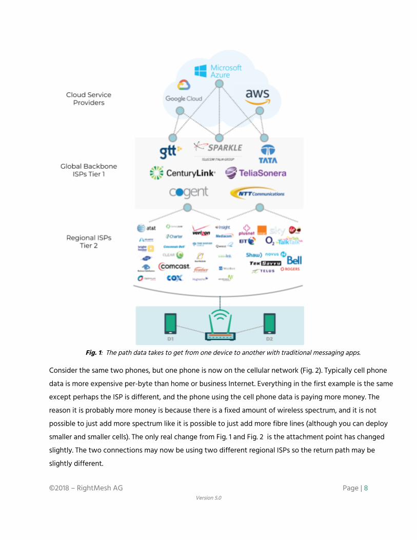
Fig. 1: The path data takes to get from one device to another with traditional messaging apps.
Consider the same two phones, but one phone is now on the cellular network (Fig. 2). Typically cell phone
data is more expensive per-byte than home or business Internet. Everything in the first example is the same
except perhaps the ISP is different, and the phone using the cell phone data is paying more money. The
reason it is probably more money is because there is a fixed amount of wireless spectrum, and it is not
possible to just add more spectrum like it is possible to just add more fibre lines (although you can deploy
smaller and smaller cells). The only real change from Fig. 1 and Fig. 2 is the attachment point has changed
slightly. The two connections may now be using two different regional ISPs so the return path may be
slightly different.
©2018 – RightMesh AG Page | 8 Version 5.0

Fig. 2: The path between two phones where one is on Wi-Fi and the other is on cellular
Companies that operate networks, and the service providers that use them, are motivated to continue with
the status quo. Facebook and Google depend on centralizing data collection. AT&T, Sprint, Verizon, Rogers,
Bell, and others depend on people willing to spend more money consuming data from (and providing data
to) centralized services. These businesses grew up out of the model where people would pay monthly to
consume television and media content: the Internet is just a newer version of the same thing. There is very
little motivation for these companies to embrace any technology which will shift this balance, and this is
©2018 – RightMesh AG Page | 9 Version 5.0

why we as a society continue to spend considerable effort to expand infrastructure. Cells are getting
smaller, more fibre is being laid, and more storage capacity is being brought online.
Infrastructure is good, and having reliable dependable and fast connectivity is extremely useful; however,
there are limits. There is only so much bandwidth available. Wireless channels are getting wider. ISPs are
asking for more licensed spectrum. Unlicensed spectrum is being saturated with networks as people’s home
routers use all of the non-overlapping channels at once with technology like multiple input and multiple
output (MIMO) antennas. As ISPs reserve more and more spectrum, there are areas where the spectrum is
not used efficiently at all and sits idle (for instance, in the countryside). Research efforts, which
opportunistically use licensed spectrum, typically don’t gain traction because the ISPs have no motivation to
change the status quo. Most ISPs would rather let the spectrum sit unused than let someone else make use
of it -- especially if people aren’t forced into their rigid service agreements and payment structures.
Internet-less Data Transmission
Going back to the examples of messaging, an easy solution is to avoid using the Internet for messaging. This
can be done today in apps. We have done this within our own YO! application, which can setup a hotspot
and allow anyone within range to share files, messages, and content without using the Internet. It can also
operate in such a way that if two devices are on the same Wi-Fi network, the messaging will occur using
only the local Wi-Fi network (not the Internet). The biggest drawback with this technology is the limited
range of a single hotspot or Wi-Fi network. The biggest benefit is all three of the layers above the hotspot
are eliminated. There are two ways in which Internet-less data transmission can be deployed over a wide
area. First, one can deploy new infrastructure that is not connected to the Internet, or only uses the Internet
when trying to communicate to devices outside of this newly deployed infrastructure. This is essentially
starting a new Tier 2 ISP. Some cities, communities, and companies are trying this approach currently. This
requires heavy investment in infrastructure.
The second method, is to attempt to enable multi-hop connectivity with the end-devices themselves
(phones, IoT devices, computers, etc.). With this second approach, the biggest drawback is not having
enough density for the devices to form a mesh. This can be addressed by introducing caching and delay
tolerance into the protocols. The other blocker thus far has been the actual difficulty in achieving multi-hop,
ad hoc connectivity with the devices without rooting the device, applying kernel patches, and using only
software.
©2018 – RightMesh AG Page | 10 Version 5.0

With several years of development and a team of PhDs, Scientists, Engineers, and advisors who specialize in
mesh networks, have built companies around mesh networks, and have experience in the telecom industry,
RightMesh has been able to create a library for mobile devices which provides the ability to avoid the upper
layers in Fig. 1 and Fig. 2 and communicate over an arbitrary number of hops without using the Internet. In
the case where density is not high enough—for instance, two neighbourhood meshes which
form—RightMesh continues to use Tier 1 and Tier 2 networks (and optionally can use cloud providers) in
order to link geographically separate meshes. Essentially, this has created a new class of network (a Tier 3
network) whereby individuals can act as their own local ISP.
P2P vs Infrastructure-less
There are other messaging apps or networks which are considered peer-to-peer apps; for example, Telegram
claims to be p2p as do Ethereum Whisper, and many others. This means the centralized aspect of AWS,
Google Cloud, or Azure may be eliminated. Connectivity is done in a peer-to-peer manner, but only if all of
the devices have a direct Internet connection already. This means the devices still have access to a wired
network, Wi-Fi using an ISP, a cellular plan, etc.
In the two devices in one room example, if the app is clever, it will detect that both devices are on the same
local area network (LAN), and use the local IP address to connect to each other and exchange data. If it is
not clever, it may perform a discovery process where the external IP address is used in the discover process
and have to traverse the network address translation (NAT) in the router at the edge of the network. In the
case where one device is on the Wi-Fi network and the other is on the cellular network, the external IP
address of the Wi-Fi network would be used along with the IP address of the cellular phone. There is usually
some added complication to getting around the firewall the cellular companies use to prevent servers
running on phones from being reachable, but hole-punching is a well established technique to get around
this (ie: running an Internet reachable server or connecting through peers which do not have firewalls or
NATs to help negotiate open ports between two peers behind incoming firewalls, or NATs) - this is how
skype, video games, and many apps function and make connections between two peers directly instead of
operating with a relay server in the middle handling the traffic.
©2018 – RightMesh AG Page | 11 Version 5.0

Fig. 3: p2p typically only removes the top layer (cloud service providers) while infrastructure-less removes all three
layers in some cases.
Wireless Mesh Networks (WMN) Vs Tradition Wireless Local Area Networks (WLAN), Wireless Personal Area Networks (WPANs), Cellular Networks, Infrastructure Networks
A Wi-Fi wireless local area network (WLAN) has a central hub called an access point (AP) which is used to
provide infrastructure to the station devices (STA). STA devices could be devices with are stationary or
©2018 – RightMesh AG Page | 12 Version 5.0

mobile such as mobile phones, computers, IoT devices, TVs, or anything that can connect via 802.11 Wi-Fi.
The main function of an 802.11 network is to remove the requirement to plug devices directly into the router.
Devices are free to come and leave and we no longer think about what happens when we return home with
our devices: they just “have Internet” when they are in range.
Fig. 4: 802.11 Wi-Fi WLAN with fixed hardware AP, some fixed and some mobile STA.
In a home router, the AP is fixed and does not move (Fig. 4). Many mobile phones can also provide AP
functionality by setting up a hotspot. This can be used to provide a local network only, or to share Internet
access. Typically, people assume that hotspots always provide Internet access, but this is not necessary. APs
on phones may be used as infrastructure by which one can provide “mobile infrastructure” to other STA
devices. In Fig. 5, a similar network can be provided; however, the wired network connection between the
router and the Internet has been replaced with a cellular Internet connection. In both Fig. 4 and Fig. 5, the
Internet connection is completely optional. The network will still function without it in some ways. For
instance, the laptop could still stream a pre-downloaded video to the television through the AP without the
Internet. The biggest difference between Fig. 4 and Fig. 5 is that if the AP phone leaves, the network will
cease to function. In Fig. 4 this is also true, but it is not so easy to disconnect a stationary router compared
to just walking away with the AP mobile phone.
©2018 – RightMesh AG Page | 13 Version 5.0

Fig. 5: 802.11 Wi-Fi WLAN with fixed hardware AP, some fixed and some mobile STA.
A wireless mesh network is different from a traditional wireless network network like a Wi-Fi WLAN or a
Bluetooth Personal Area Network (PAN). Instead of offering a central hub that offers a circular bubble of
coverage, an 802.11s wireless mesh network provides a cloud of coverage that can span a much larger area. It
does this by linking together many hotspot-like routers to form one continuous network (Fig. 6).
©2018 – RightMesh AG Page | 14 Version 5.0

Fig. 6: 802.11s network with three MPs and one Internet connection
Typically, wireless mesh networks are deployed using hardware, often on street poles or small towers similar
to cellular deployments. The difference between a cellular network and a wireless mesh network is usually
that a cellular network has fibre connecting each tower to infrastructure. In some cases, a cellular network
can be similar to a mesh network if the towers are connected together with a wireless backhaul. This is often
done in more rural / less dense areas since the wireless backhaul may not be able to carry as much traffic as
a fibre line and is affected by things like weather more easily. However, it is much more affordable. When a
wireless backhaul is used, the backhaul is often on a different frequency than the one which the wireless
handsets connect to the towers with. In Fig. 7, the cell towers with yellow lines are connected via fibre,
while the topmost cellular tower uses a wireless backhaul.
©2018 – RightMesh AG Page | 15 Version 5.0

Fig. 7: Cellular network with a mixture of wired and wireless backhaul
A wireless mesh network often has only a small subset of devices which directly provide Internet into the
network. The mesh network devices must then maintain routes / paths towards the Internet. Further a
wireless mesh network is different from a cellular network because wireless mesh networks often operate in
free spectrum, whereas cellular networks operate on licensed spectrum. Cellular networks also have
additional hardware infrastructure to handle billing, handover and other features depending on whether it is
a 2G, 3G, 4G, or other network. In Fig. 6, this would be contained in the outdoor transmission equipment and
radio relay stations. In a mesh network, this logic is typically contained within the mesh hardware itself.
Mesh networks are typically designed to be deployed with less planning than a cellular network. They are
designed to configure themselves automatically while reacting to environmental conditions and congestion.
There are typically more paths available, whereas a cellular network may be designed to minimize
infrastructure cost (i.e., focus on few expensive backhauls).
“Software Only” Mobile Mesh vs Infrastructure Mesh, Hardware Mesh
A mobile wireless mesh network (mWMN) is a variation of the wireless mesh network where the routers are
mobile devices (phones) themselves. This is quite different from the hardware mesh networks for several key
reasons. First, the mobile devices are not in a fixed location. This means network partitioning may occur
(where the network splits) making some portion of nodes unreachable to others for some period of time.
©2018 – RightMesh AG Page | 16 Version 5.0

The mobile devices, which are typically phones, do not often support advanced features that are required to
support meshes in the same way that hardware can. On a hardware router, the manufacturer controls the
chipset and operating system on the device and can apply kernel patches and access the routing table. This
means protocols like 802.11s (a mesh networking standard for Wi-Fi devices) can be supported by patching
the OS kernel as long as the Wi-Fi chipset supports it. 802.11s allows devices which are located many hops
away from each other to appear as if they are located nearby. From a link-layer perspective, they all appear
to the layers above as if they are on the same WLAN (hotspot). Essentially, it converts all devices which
would normally be separate Access Points (APs)/ (hotspots) into Mesh Points (MPs) as in Fig. 6.
In Fig. 4 and Fig. 5, internet protocol (IP) addresses are provided to all of the devices because the device
acting as an AP also provides a dynamic host configuration protocol (DHCP) server typically. The job of this
server software is to map the media access control (MAC) address to an IP address. A MAC address is the
physical address of the Wi-Fi chip in the phone, laptop, or other device and take the form
‘00:00:00:00:00:0X’. These are meant to be unique across all devices; however, these can be faked
sometimes by software and there are no guarantees they will actually be unique since it depends on
cooperation from the manufacturers of Wi-Fi devices. An IP address is used by the routing protocols to
determine how to get packets from one device to another.
Fig. 8: Two APs with different sets of IP addresses
For instance in Fig 8, the phone with IP 192.168.1.4 on the left, may wish to send a data to the the TV on the
right with IP 192.168.1.25. During the DHCP discovery process (when the devices obtain their IP address from
192.168.1.1, they set their default route to 192.168.1.1. When they encounter an IP address they don’t have
stored locally yet, they will send a request to their default route to determine where to find this device.
192.168.1.1 will tell 192.168.1.4 that it it can reach 192.168.1.25 through 192.168.1.1. It is also possible to reach
©2018 – RightMesh AG Page | 17 Version 5.0

192.168.5.4 in a similar way; however, when the data arrives at the router, something special called Network
Address (NAT) is required to determine which device the incoming traffic from the Internet is intended for.
If we were able to link the TV at 192.168.1.25 locally with 192.168.5.4, there would need to be a similar
translation done to convert the IP addresses from the left network to the IP addresses in the right network.
There are protocols which can achieve this type of translation; for example, the border gateway protocol
(BGP) can perform such translations..
Fig. 9: IP Addressing in a 802.11s mesh (all devices in same subnet range)
The alternative is an 802.11s mesh, or something similar using Zigbee or Bluetooth 4.x or higher. In these
types of meshes, the mesh forms at the link layer, meaning that all of the devices appear as if they are all on
one hotspot, or all on one wired network. This means all of the devices can obtain IP addresses in a
consistent manner and routing tables can be built by the operating system quite easily (Fig. 9).
©2018 – RightMesh AG Page | 18 Version 5.0

IP Addressing Limitations on Mobile Phones
On an Android phone, 802.11s cannot be used without rooting the device. So without being able to use
802.11s, the only means to form a mesh on the mobile phone are through technologies which were really
only meant to connect devices in a hotspot model (one hop away from a central device), and technology
must be developed to link these hotspots together. Even if the hotspots are linked together, an IP address
only makes sense within the local hotspot, and not any further beyond. As a result, it would require
something like BGP to be implemented (since it would again require rooting the phone to make
modifications to the routing table).
Since it takes a rooted device to manipulate the routing table directly, it is not possible to tell the routing
table how to reach devices in other hotspots easily. Similarly, a MAC address from a BT connection is
meaningless when trying to route packets using TCP/IP (for an end-to-end connection across the mesh).
Further, even if it were possible to do such a thing, normal TCP does not allow for multiple paths unless the
mTCP protocol is used, again which requires a rooted device to use.
End-end data transmission limitations
One of the biggest challenges with building a mesh using existing TCP on the phones is that of end-to-end
communication and path reliability. As these unreliable links grow in number of hops, the likelihood of a
successful delivery becomes more and more remote. Consider a path that is ten hops long, where each path
has a 99% chance of success on each hop. The probability a packet will reach the destination is 90.4%. If the
success rate of each individual hop drops to 90%, the overall probability drops to 34.9%. In order to improve
the overall success rate, end-to-end protocols must also work with one-hop protocols to increase the
success rate of the individual hops. A complete end-to-end re-transmission must be avoided wherever
possible.
Core RightMesh Technology Overview
The core of RightMesh is comprised of:
1. A local mesh, which aims to build a platform-independent, locally-connected, multi-hop, ad hoc
network between the phones;
©2018 – RightMesh AG Page | 19 Version 5.0

2. A globally-connected network of these local meshes
3. A micropayment channel system that allows for mesh users to sell their Internet data into the mesh,
and other mesh users to purchase this data. Devices along the path on the mesh are rewarded.
Devices which provide reliable, consistent Internet connections, an Ethereum node, and RightMesh
tokens are also rewarded for facilitating Internet transmission between meshes.
4. An API / SDK / Library which allows developers to build RightMesh apps
5. Reference applications for Android, Java, and the cloud to support a growing ecosystem.
The RightMesh networking stack shown in Fig. 10, builds off of the success of existing Internet protocols. The
design is a layered design, so improvements can be made iteratively on each of the layers without having to
do a full redesign of the entire system.
Fig. 10: Layered RightMesh Protocol Stack
Local Mesh Connectivity
The RightMesh protocol in conjunction with the RightMesh Android library handles autonomously forming
connections via Bluetooth, Wi-Fi, and Wi-Fi Direct between devices via a peer discovery / topology creation
©2018 – RightMesh AG Page | 20 Version 5.0

protocol. RightMesh devices are assigned a locally-generated unique identifier in the mesh based on an
Ethereum public address which we call a MeshID. This MeshID maps local and changing IPv4, IPv6 and MAC
addresses to a single, consistent global device identity. The mesh protocols and systems form an
autonomous self-configuring, self-healing, self-optimizing, self-protecting (self-*) system. The locally
connected multi-hop ad hoc network is comprised of a hierarchical layered architecture. This architecture
starts at the lowest layers by abstracting existing network stack one-hop links as if they are link layers in a
traditional network stack. For instance, a Wi-Fi link between a Wi-Fi hotspot and a Wi-Fi client is treated
more closely to how 802.11 treats a MAC layer link rather than as a link that already has an IP address and
could support TCP connections on. On top of this, an end-to-end transmission control protocol is
implemented which takes into account our unique (and patent pending) switching techniques to link
hotspots together, as well as this hierarchical routing table. This transmission protocol ensures reliable
delivery between devices on the mesh since the lower layers use UDP. It also has the ability to send data
across multiple paths at once and recombine at the receiver side. This was influenced by multipath TCP
(mTCP). The protocol also has some limited ability to perform some delay tolerance because it has some
loose coupling with the the lower layer, allowing for limited retransmissions at each single-hop along a
multi-hop path to avoid end-to-end timeout and retransmission. This was motivated partially by protocols
like Licklider Transmission Protocol (LTP).
Bluetooth 2.0 RFCOMM was used as a starting point because it was possible to make a connection with
other peers without requiring pairing. With our Wi-Fi Direct and Wi-Fi implementations, the same is also
possible. RightMesh makes connections programmatically using three different types of next-hop links.
Within our design, RightMesh can add support for higher versions of Bluetooth as we figure out ways to
make the connectivity occur without user intervention. We may be able to do this by making use of some of
the other connectivity pathways we already have as a way to signal information between devices to set up
the faster connections.
The autonomous connectivity layer does the job of assigning internal roles to devices in our network. This
decides whether a device will be in hotspot mode or not, which devices to connect via Bluetooth, whether
to use Wi-Fi, Wi-Fi Direct, both, or all three. The RightMesh approach to autonomous connectivity is
something that will constantly get better, but it was kept simple as a sort of MVP state. In fully-automated
mode, the user will only need to select whether they wish to participate as a forwarding node, and whether
they wish to share their Internet, or not. If they wish to sell their Internet, they will also need to set the price
©2018 – RightMesh AG Page | 21 Version 5.0

they wish to sell it for (in Mesh Tokens). Conversely, if the user wishes to consume Internet, they must set
the price they are willing to purchase Internet for (in Mesh tokens). If they do not wish to pay any mesh
tokens and there are no free paths, the apps will still function, but they will only be able to use a localized
version of the mesh. It is also possible, in advanced mode, for users to control exactly which internal role the
device should use. This capability is packaged automatically with every app that uses the RightMesh library
via the RightMesh Service.
We make use of a clustered routing where hierarchy is imposed on the devices based on the internal roles
the devices are assigned. This means that not every device needs to know the connectivity to every other
device, allowing the RightMesh network to scale significantly higher than competing approaches. This same
cluster-based architecture lends itself well to enabling caching in the network which is also on our roadmap.
For instance, the same nodes that are cluster heads would be ideal candidates to also be a cache of
common apps, ads, and multimedia content.
Combined with the routing layer and the one-hop connectivity layer, multipath end-to-end reliable
communication forms a really unique and valuable part of the RightMesh solution. This is what distinguishes
RightMesh from most of its competition. There are a few ways communication typically occurs in mobile
meshes:
1) Broadcast to everyone (either using UDP + existing broadcast / multicast approaches, or TCP on a
link by link basis - no end-to-end capability)
2) Single-path end-to-end TCP (with many limitations as outlined below)
3) Best-effort UDP communications with no reliability
Many existing mesh approaches simply make use of existing TCP to provide end-to-end connectivity.
However, TCP is not well suited to a mobile mesh network for several reasons:
1. Unless rooted, mobile phones do not let the user customize the version of TCP being used.
2. Mobile mesh networks are made of devices that frequently connect and disconnect. When this
occurs, a TCP connection would require end-to-end reestablishment of a connection, with
something like a 3-way handshake.
3. With IPv4 It is often impossible to make an end-to-end TCP connection because the IP address in
one hotspot means nothing to the neighbours three hotspots away. As such, there is no mechanism
to exchange this information between hotspots and have the routing automatically work. In this
©2018 – RightMesh AG Page | 22 Version 5.0

case, it may be possible to have TCP on each single-hop link, but there are still the same drawbacks
from some of the other bullet points to be aware of. In the case of performing TCP on each link,
there is still no mechanism to prevent an entire end-to-end path from being saturated with traffic
(the congestion control will only work on a link-by-link basis, leaving the queues at the intermediary
nodes to potentially overload).
4. TCP often gets interference and congestion mixed up. It may start a backoff unnecessarily thinking
that congestion is occurring when it is experiencing temporarily poor network conditions due to
external factors (e.g., a vehicle driving through the path of the signal, a microwave being turned on, a
tree being between two people who are moving, etc.).
5. The TCP on most non-rooted phones cannot handle multiple paths. This means even if your device
has a Bluetooth, Wi-Fi, and Wi-Fi Direct connection available, it is only able to use a single one of
them for one data stream. This also applies to Internet connections out of the mesh as well. There are
existing versions of TCP that can do this, notably mTCP; however, it is almost never included in
commercial phones.
RightMesh borrows concepts from delay-tolerant network protocols such as LTP and has combined them
with multipath-TCP to create a delay-tolerant protocol when the network becomes fragmented, but high
performance in the cases where it is well connected. RightMesh also uses concepts from Software Defined
Networks, Overlay networks and self-* networks.
Rightmesh supports end-to-end encryption. More details are provided in the encryption section later in the
document.
Global Connectivity - Linking Meshes Together
While one day it may be possible to link the entire world with one “local” mesh without using any of the
existing infrastructure, this is not practical today. To make RightMesh more practical sooner, and to enable
apps that work like everyone expects, it is necessary to be able to link separate RightMesh meshes together.
Consider a mesh in Vancouver, Canada and a mesh in Dhaka, Bangladesh. If there is at least one device in
each mesh which are willing to share their Internet data into the mesh, then these two geographically
separate meshes together can form one large mesh. The distance between the meshes doesn’t need to be
that extreme: it could be one neighbourhood connecting to another neighbourhood in the same town.
©2018 – RightMesh AG Page | 23 Version 5.0
There are few problems when trying to do this type of linking. First, is that cellular companies and ISPs often
block incoming server ports on mobile devices, making it difficult to make a connection directly from one
phone to another on the Internet. Second, if there are multiple devices behind one router (like at an office,
or home), network address translation (NAT) is required to map outgoing connections back to the device
which made the request. For instance, if your phone and computer both visit the Google website at port
443, and the phone searches the term “hello”, and the computer searched “mesh”, NAT would know to route
the first request to the phone, and the second request to the computer (this is a massive simplification, but
this is the general idea). In order to get around these problems, RightMesh must provide a layer which allows
devices which aren’t behind NATs and Firewalls to facilitate connectivity between devices that are. This
layer is called the superpeer layer, and takes motivation from other p2p protocols, video conferencing, and
other well known apps which use UDP hole-punching.
Currently, global connectivity is limited to connecting multiple separate geographic meshes together, and
does not support “general purpose Internet connectivity”. This means, RightMesh devices can’t yet natively
route Facebook Messenger into the mesh unless Facebook integrates RightMesh into their app. Similarly, the
phone user will not be able to open their web browser and visit the Google homepage. They will be able to
use a RightMesh app in Vancouver, and talk to someone in Bangladesh on the same app as if they were on
one large mesh network. General purpose Internet requires us implementing a proxy on the phone side
which translates Internet traffic into RightMesh traffic towards superpeer devices. At the superpeer devices,
a NAT would be implemented which would also translate the RightMesh traffic back into IP traffic. General
purpose Internet connectivity is on the roadmap for 2019.
Micropayment Channels for Incentivization
With the local mesh connectivity and the global connectivity through the superpeer layer, it is now possible
to link meshes together technically. However, without incentivization the only people who will share their
Internet into the network are those who have low-cost data and a kind-hearted nature. This model works for
some networks like Tor, which operates on a voluntary basis and depends heavily on institutional
participants who encourage free speech, such as universities. The problem with a mesh adopting this model
is that the mesh requires local participants to be willing to share their data into the network. This most often
means individuals. In order to motivate these individuals, we believe they should be able to earn something
for providing their data, their battery life, their storage, their sensor information, and their processing power.
©2018 – RightMesh AG Page | 24 Version 5.0
To enable incentivization, RightMesh has developed a micropayment channel solution based on microRaiden
and implemented at the superpeer layer. This allows devices to sell their data into the network at their own
set price, while allowing other devices to purchase this data at a market rate (the protocol will select the
lowest cost route available). Devices in between the buyers and sellers are incentivized for participating, and
those operating the superpeer layer also have the opportunity to earn tokens for staking their tokens and
facilitating the communication (note: these devices provide UDP hole-punching and payment hub
functionality as well).
The RightMesh API / SDK / Library
The RightMesh API provides developers with an event driven framework enabling simple discovery /
updating / removal of other peers in the mesh running the same app, sending and receiving data, and
end-to-end encryption without the developer being skilled in any of these areas. On top of this discovery
protocol, the API packaged with the protocol handles splitting up datastreams into packets, which are
routed across the multi-hop mesh network using the parts of the protocol responsible for reliable
end-to-end communications and delay tolerance. When a full datastream arrives at the destination, an event
fires at the receiving peer notifying the developer some new data has arrived.
One of the philosophies behind RightMesh is that a user should never have to be involved to pair a phone,
join a Wi-Fi network, setup a hotspot, or otherwise be involved. It should operate similar to how a cellular
network manages handover between cellular towers without the users of the phones knowing that it is
even occurring. However, if the user wishes to use advanced functionality and control this to some extent,
this should still be possible. He or she should be able to disable Wi-Fi or Bluetooth and the mesh should use
whatever is still available to continue operation as best as it can with what is provided by the user.
A second philosophy of RightMesh is that the user should always be in control, not the developers. That is to
say, developers using RightMesh should not be able to control whether the app only participates as Wi-Fi
client, it turns on hotspot mode, or Bluetooth. If this were possible, one could imagine a developer creating
an app which only participates in RightMesh as a “leech” on the network, never providing any service to
others. If a user wishes to operate in this mode, this is perfectly acceptable as they will have fewer
opportunities to earn rewards operating as periphery / leaf nodes in the network. In order to earn tokens by
relaying traffic, one must operate as infrastructure and provide service or virtual infrastructure to others.
©2018 – RightMesh AG Page | 25 Version 5.0

Developers of a RightMesh app get the benefit of having the power of RightMesh built into their apps
natively. RightMesh will send data through the local mesh when possible and fall back to the Internet when
not possible, greatly increasing the efficiency of communications (most apps today are designed to
communicate directly with the Internet even if the person you are sending data towards is in the same room
as you). The increased efficiency may result in lower energy usage in the network as a whole. For instance,
offloading connectivity from a 4G network to Wi-Fi or Bluetooth connectivity for some portion of the
devices could lower energy consumption. It may also result in increased efficiency in terms of bandwidth
costs for app providers. Consider an app like Facebook Messenger or Slack where messages move from the
phone to a cloud service, back down to a second phone in close proximity. There would be Internet costs for
these services providers for the data to move to centralized servers and back to the phones. With
RightMesh, this transmission could occur locally between the two phones. If the phones are farther apart, it
would fall back to a similar model of sending to and from the Internet. However, if there are large groups of
phones for the data to be sent to, RightMesh could help again. In this case, even across the Internet, if some
of the phones exist on a local mesh together, RightMesh would send across the Internet once for the entire
local mesh, where it would then be distributed to all of the receivers using the mesh protocols. The cost
savings here would scale with the number of receivers in the same mesh.
Users of RightMesh apps will also benefit from the same types of cost savings. The limited bandwidth on the
existing infrastructure will be used to obtain new content for a mesh, and existing content can be
distributed locally within the mesh. Existing telcos are motivated to have everyone pay to consume the
same data over and over again. While people should pay something to consume content (to reward the
creators, and the parties that facilitated the transmission), RightMesh believes this cost should be
significantly lower once the data has been distributed into the mesh compared to the initial transmission
(since the first hop from the Internet is where bandwidth is limited by the availability of low cost
infrastructure).
Developers will also get the benefit of all of the other RightMesh enabled apps. Density is often a concern in
mesh networks; however, as a developer it is not required to have high density via a single application. For
example, an emergency app could forward data through a device only running a messaging app (if the app
was built with RightMesh), and that could forward through a device running a game until it eventually
reaches the other device running the emergency app on the other end.
©2018 – RightMesh AG Page | 26 Version 5.0
RightMesh apps are not required to be deployed only on Android devices. It is possible for RightMesh to run
on any device that supports Java runtime. This could be computers, raspberry Pi’s, remote weather stations,
sensors, and other devices. On these devices, there is less autonomous connectivity built-in; however, they
are well-suited to act in a more infrastructure role, providing hotspots for other autonomous mobile phone
devices to automatically make connections with them. It is also possible to run a Java RightMesh app on a
cloud service if one wishes to develop an app that interacts with traditional centralized architectures like
web servers, relational databases, etc. An example of this type of app might be a server app which collects
sensor data from a variety of sensors scattered throughout the RightMesh ecosystem and stores it in a
centralized relational database. There would be a corresponding RightMesh sensor app that would run on
the sensor devices and send its updates to a set of sensor sink apps running on the cloud. RightMesh
protocols would figure out how to get the sensor data there. Corresponding websites could then query the
relational database in the normal fashion and display the sensor data live as it is being returned from the
mesh.
RightMesh Reference Apps, Ecosystem
In order to kickstart the development of RightMesh apps and an ecosystem around RightMesh, we have
begun providing open source reference implementations of various types of apps.
The first and simplest apps are of the “Hello World” variety, including the “Hello Mesh” app. Related to this
we have released a Java version of the same app called “Hello Java Mesh” which can be run on a computer
and interoperate with phones on the same mesh. Phones and computers can send a “Hello Mesh” message
to each other, and the developer can see how similar the code is on either side, even though the Android,
Linux, and Windows platforms are quite different.
During some of our testing, we developed a “ping-like” app called “Reflect” which can be used to send a ping
message from one phone to another, and replay the message back to the sender. This can be used to test
connectivity on the mesh.
We also created an app called “Ripple”, which was used to demonstrate visually how the routing protocols
on RightMesh work. In this app, it is possible to send a “color” to another phone in the mesh. All of the
devices along the path will change to the sent “color” as the packets move across the mesh. This
©2018 – RightMesh AG Page | 27 Version 5.0
demonstrates that RightMesh does not use broadcast routing, and in fact, computes a unicast route
between two peers.
Most recently, we released a messaging app called “MeshIM”, which supports peer discovery, basic user
profiles, and messaging between peers using RightMesh.
To support the general blockchain and Ethereum communities, we have begun an open source port of the
microRaiden project from python into Java (the language that RightMesh is currently written in).
Finally, in order to enable developers to create their own superpeer implementations and control channel
creation and management strategy, we have provided a reference implementation of the RightMesh
superpeer.
3. The Local RightMesh Network
The aim in this section is to explain the details about the local network connectivity protocol in greater
detail, covering internals to the library such as:
1. MeshID which replaces IP addresses, MAC address, and other addressing schemes
2. MeshPorts, which are used to multiplex traffic from the RightMesh service to any number of apps
running at the same time
3. Internal roles which dictate how a device performs requests and responses within the protocol
4. Peer discovery, one-hop transmission, and control packets
5. Autonomous formation
6. Data transmission
7. Routing
8. Encryption,
9. Local multicasting and broadcasting.
In all of these cases, the local aspects of the mesh formation and data communication are emphasized. The
next section goes into detail about Internet communication.
©2018 – RightMesh AG Page | 28 Version 5.0

MeshID Given that RightMesh is able to support connecting together multiple Wi-Fi hotspots—each with their own
set of IP addresses (both IPv4 and IPv6), as well as connecting via Bluetooth (with MAC addresses), and in
the future other networks where there may be even more different addressing schemes—one the first
problems we aimed to solve is how to identify devices in the network uniquely. While building YO! (one of
the company’s first offline apps), this was handled in the typical manner where unique IDs are generated
from an Internet-connected server. In a mesh where the devices may never touch the Internet, or may not
for a long period of time,or the Internet is censored, this makes it impossible to form the identity. It is a
chicken and egg problem. With RightMesh, we needed to generate the ID on the device without requiring
the Internet to do so. Researching this problem led the company into cryptocurrencies, where this problem
had already been addressed and proven to do so in a way where there is almost no chance of ever
generating the same ID twice.
Currently, RightMesh generates an Ethereum account using the Ethereum-j library. The account generated is
compatible with any popular Ethereum client, such as geth, mist, or myetherwallet. This identity is generated
once when the RightMesh library first launches on the device, and remains on the device until the user has
removed it manually. This means if RightMesh apps are installed and uninstalled, the same identity will be
present unless the user removes it. All RightMesh apps that are running at the same time also share the same
identity, similar to how your computer has the same IP address for your web browser, your Slack client, and
your games (unless you leave your house and travel to work with your computer and get a different IP
address at your new location). With RightMesh, despite all the movement and changing IPs while you move,
your RightMesh identity will stay constant. This permanence is how other devices in the mesh will always be
able to deliver data to the right device.
The identity on the mesh is the public Ethereum address that gets generated along with the account. The
generated account is encrypted using a default password that RightMesh provides (as a proof that the
service can do the encryption correctly). It also contains the public and private key associated with the
account to ensure it works on the Ethereum network when executing transactions. At launch time,
RightMesh aims to have the MeshID functioning such that a user will be able to set their own password for
the encryption so that their account is locked and protected by the password as they would expect with an
account generated by any other client.
©2018 – RightMesh AG Page | 29 Version 5.0

Mesh Ports, Service Architecture, Multiplexing to Multiple Apps On Android, the RightMesh library functions as a service. Multiple apps can make use of the service at the
same time, provided they are all listening on different mesh ports. The RightMesh Developer’s Portal (shown
in Fig. 11) allows developers to register keys which are associated with each mesh app they build. When
registering the developer key, they also pick which mesh port(s) the app will be listening on and verify that
no other apps are using the same key. The developer who created the key may share access with other
developers, so teams can collaborate on the same app without sharing login information. If one of the
developers leaves the project, their access to generate valid keys may be removed. Farther down the
technical roadmap, the developer portal will also be used to help developers debug mesh connectivity
through visualisation, file bug reports, deploy updates through the mesh, and as a mesh analytics platform.
Fig. 11: RightMesh Developer’s Portal
When the app connects to the MeshService, the service parses a cryptographically-signed license key that is
generated at compile time and packaged with the app by our RightMesh Gradle plugin. (An example Gradle
file for compiling with RightMesh can be found on our “HelloMesh” project on GitHub. The signed license key
file requires a valid developer account with access to the key at compile time. Inside this license is the
developer key, and mesh ports that the app is allowed to use. Again, similar to the MeshID problem, we tried
to design this system so that apps may form meshes without requiring Internet access to validate the library
(although we make the assumption that Internet access is available at compile time for the developers).
©2018 – RightMesh AG Page | 30 Version 5.0

Fig. 12 shows the RightMesh Service running on a single phone, with three different apps running at the
same time. They are all running on different mesh ports. Each app also comes with a portion of our library we
call the AndroidMeshManager, which performs all of the logic to connect to the service, and to fire events
such as Peers joining or leaving the network, data arriving, or the result of encryption keys being exchanged.
Fig. 12: Multiple Apps running on the same device, using a common service
In Figure 13, a mesh with three devices is shown. Notice that device one has three apps running. Apps are
only notified of peers which are running the same app (the developer does not get access to all of the
devices on the mesh, even though other devices may act as forwarding nodes in order to reach other
devices). For instance, App #1, listening on mesh port 9999 will only “see” peers 1 and 3. App #2, will only
“see” peers 1 and 2. App #3 will “see peers 1 and 3 as well. Data being sent from peer 1 to peer 3 will be sent
through peer 2, even though it isn’t running either of the apps that peer 1 and 3 are using.
On Java, RightMesh does not currently support a service environment, so only a single RightMesh app can
be run on one computer, IoT device, or sensor at a given time, however it still must bind to a MeshPort as
this prevents other apps from sending data to the device, or intercepting data from the device.
©2018 – RightMesh AG Page | 31 Version 5.0

.
Fig. 13: Multiple devices communicate through the service, where each phone may have different sets of apps
Internal roles (MASTER, CLIENT, ROUTER) Internally, RightMesh labels endpoints of links depending on the role the device is playing within that link.
The role depends on the underlying technology (Wi-Fi, Bluetooth, Wi-Fi direct) and how the technology is
being used.
Wi-Fi MASTERs act like traditional network servers and listen for incoming requests and respond to the requests.
MASTERs are also key hubs in the topology. A Wi-Fi device operating in hotspot mode would be a MASTER.
CLIENTs act like typical clients and send outgoing requests and wait for responses. They are also able to
listen to other requests and responses and process them without necessarily responding. A Wi-Fi client
©2018 – RightMesh AG Page | 32 Version 5.0
device would first connect to a RightMesh Wi-Fi hotspot, determine the MASTER IP address using the DHCP
gateway and send requests for topology discovery.
ROUTERs are devices which are linking two different sub networks. For Wi-Fi links, this would be a switching
device (one which is in range of two or more hotspots / MASTERs). This device would be responsible for
communicating topology information about each MASTER subnetwork to all of the other MASTER
subnetworks. Functionally, it is similar to a CLIENT device, in that it is operating as a Wi-Fi client; however, it
virtualizes its connectivity by dividing the time it stays connected to a particular MASTER and then sending
discovery requests to each upon leaving and rejoining other MASTERs.
The connection process in Wi-Fi works as follows. The MASTER devices turn their hotspot on and name the
hotspot with a set RightMesh pattern. This lets RightMesh CLIENTs and ROUTERs filter out trying to connect
to hotspots which may not be running the RightMesh network. CLIENT devices use blacklisting and
manipulation of the Android Wi-Fi configurations settings to force the phone onto a RightMesh hotspot.
Once an IP address is obtained, the RightMesh topology discovery protocol starts by sending a HELLO
request. The MASTER devices respond to the HELLO request which includes some exchange of topology
information. Devices configured with the ROUTER role will act the same way a CLIENT does if there is only a
single MASTER in range. As soon as more than one MASTER is in range, the ROUTER device will change from
operating as a CLIENT to operating as a switching device, and will change the topology discovery protocol
packets it sends. It will also periodically switch between the MASTERs and exchange topology information
from each side.
Bluetooth Roles on Bluetooth work a bit differently as each Bluetooth device simultaneously acts as a MASTER and a
CLIENT. If a device has more than one Bluetooth connection, it acts as a ROUTER since it may be linking two
separate subnets in the same way our switching devices work. Since our philosophy is that the user should
never have to make a pairing with another phone manually, we wanted to use a Bluetooth version on
Android that would support connecting without having to agree to pair, or enter a pin. The way we were
able to make this work was with Bluetooth 2.0 RFCOMM which is intended for connecting to embedded
devices without any input device to provide pairing information on. Android phones are also able to act like
a Bluetooth 2.0 RFCOMM device (in addition to connect out to one), which is why they can act as a MASTER
or a CLIENT.
©2018 – RightMesh AG Page | 33 Version 5.0
On Android, it is possible to support several Bluetooth connections at once. It may be as high as 8 - 10
connections, but in practice it is usually more often that it is 3 - 4. In the case where more than a single
connection is possible, the phone can sit listening for incoming connections at the same time it is making
outgoing connections.
The connection process for Bluetooth devices is a bit different from Wi-Fi devices since a device can act as
both a CLIENT and a MASTER. In one thread, the device acts as a MASTER, which sets the device to be
discoverable and listening on one virtual channel. In another thread, the device acts a CLIENT, performing
Bluetooth scans. When a scan completes, a list of Bluetooth MAC addresses are provided along with the
device names. Similar to the Wi-Fi CLIENTs, Bluetooth CLIENTs can filter out devices that don’t have the
RightMesh device pattern to avoid connecting to Bluetooth devices which aren’t running RightMesh. When
making the connection, once the connection is formed, the device acting in the CLIENT role sends a HELLO
request to the device running in the MASTER role which responds with topology information.
When a device has made a Bluetooth connection to two or more devices, it changes its role slightly to
behave more like a ROUTER. The device still maintains its MASTER or CLIENT behaviour when it comes to
determine which device sends outgoing requests and which answers, however, the topology information
exchanged changes slightly as multiple networks may need to be linked together.
Wi-Fi Direct Wi-Fi Direct works almost the same as with Wi-Fi, with a few key differences. Wi-Fi Direct hotspots are
invisible to the user (in a normal Wi-Fi hotspot there is an icon in Android that shows a hotspot is running).
Wi-Fi Direct hotspots also have the ability to advertise extra data to the Wi-Fi Direct clients. In Android, with
Wi-Fi Direct hotspots it is not possible to change the name of the hotspot: it always takes the name
DIRECT-<something>. However, we can append information in a hashmap which can be advertised to Wi-Fi
Direct clients. In this hashmap, we RightMesh Wi-Fi Direct MASTERs provide a network name similar to
setting the SSID in Wi-Fi or the device name in Bluetooth. We also provide the MeshID of the MASTER
device.
The biggest difference between a Wi-Fi Direct MASTER and a Wi-Fi MASTER is that a Wi-Fi Direct MASTER
can also be a Wi-Fi CLIENT or Wi-Fi Direct CLIENT at the same time. We consider these “outgoing”
©2018 – RightMesh AG Page | 34 Version 5.0

connections or CLIENT connections, while the MASTER connections are incoming connections. One
important note though, is only one outgoing connection may be made at once, unless a device is running in
Wi-Fi Direct ROUTER mode, which would use the switching technology that Wi-Fi ROUTERs use. The reason
that MASTERs advertise their MeshID is so that RightMesh can attempt to create a long chain of
non-switching Wi-Fi Direct MASTER/CLIENT links. Another thing to note is that a normal Wi-Fi CLIENT cannot
connect to a Wi-Fi Direct MASTER, only the opposite direction works. Another important note: a Wi-Fi Direct
MASTER can act as a Wi-Fi client of an external Wi-Fi hotspot at the same time, which makes it a good
candidate to share external Wi-Fi into the RightMesh network.
Similar to the Wi-Fi MASTER / CLIENT behaviour, the MASTER sits waiting for incoming connections from
CLIENTS or ROUTERS. The CLIENT device first inspects the extra information from the MASTER to see if it is in
fact a RightMesh MASTER (does it provide the pattern, the MeshID, etc.). It then attempts to associate with
the MASTER. Once an IP address is received, it proceeds in the same manner as a Wi-Fi client.
Packet Structure The packets are defined using Google Protobuf. There were several reasons for choosing this format.
According to the project page, it is a “language-neutral, platform-neutral extensible mechanism for
serializing structured data”. This way, if we decide at a later date to support c/c++ for embedded devices,
IOS, or other architectures, it will easily be possible. The only part that would need to be re-implemented is
the logic that handles the packet types, rather than having to hand code the packet format as well. The
other main benefit is the efficient encoding of the on-wire, or in the RightMesh case, on-air data. There is
some early evidence that Protobuf performs much better than for example, JSON. There are also more
detailed performance comparisons with other serialization libraries as well. When designing RightMesh, it
was well known that we would be using links such as Bluetooth which provide limited bandwidth. Also, in
dense deployments, bandwidth will also be a luxury. Further, since the protocol is running on mobile
devices, it is important for the phones to be able to quickly parse the packets. So we needed a structure that
supported compacting the data, while also processing quickly, which made Protobuf a good candidate.
While we are not providing more details on the exact packet structure currently, it is because it is still in flux.
Once it is ready, we will collaborate on open standards for interoperability with RightMesh and other
partners.
©2018 – RightMesh AG Page | 35 Version 5.0

Packet Types and Priorities RightMesh packets are delivered to the one-hop neighbours using priority queues. Each one-hop link has its
own set of priority queues. For instance, a device connected to a peer with both Wi-Fi and Bluetooth would
have one set for the Wi-Fi link and one set for the Bluetooth link that are independent of each other. First,
the highest priority queue is emptied. Then, the next priority proceeds one packet at a time, with a check for
a higher-priority queue not being empty. If a higher-priority queue has packets, the higher-priority queue is
emptied and then the lower-priority queues are served in priority order.
Acknowledgement Packets (ACK)
The highest priority queue is ACK. These are one-hop acknowledgements of control packets (and often
contain topology information in them), DATA, and DATA_ACK packets. The reason for making an ACK the
highest priority is that if other control packets or data packets are sent in high numbers at the same priority,
they will overwhelm the ACKs—potentially causing even more control or data packets to be issued.
Control Packets (HELLO, GOODBYE, JOIN, LEAVE)
There are HELLO packets which are used to indicate a device is still connected to (or joining) the mesh using
a CLIENT link, and to request topology information from a MASTER side of the link. GOODBYE packets can be
sent from any role type and indicate that a device is going to leave the mesh. JOIN packets are used to link
together two or more separate sections of mesh together (for instance, linking two hotspot networks
together). These are sent by ROUTERs, Bluetooth, or Wi-Fi Direct links which are linking together sections (in
either MASTER or CLIENT link role). LEAVE packets are used to indicate a switching ROUTER link is about to
temporarily LEAVE one section of mesh and JOIN another. In all of these cases, MASTER sides of the link are
responding with the ACK packet containing particular topology information.
End-to-End Data Acknowledgement (DATA_ACK)
The next priority after ACKS and control packets, is DATA_ACKs. These are a special type of ACK—which is
an end-to-end ACK that is sent from the final destination of the packet and potentially multiple hops away
from the source. Again, if these don’t take a higher priority over DATA packets, the data transmission
protocol may flood the network with DATA packets, causing the DATA_ACK to be lost when actually the
©2018 – RightMesh AG Page | 36 Version 5.0

DATA has arrived successfully, leading to unnecessary retransmissions. We give the DATA and DATA_ACK
packets lower priority from control packets because if these packets overwhelm the topology signalling, it
will cause devices to think entire connections have broken, or updates about connectivity will get ignored
when devices are sending high throughput data through the network. More details regarding when
DATA_ACK packets are sent are provided in the Data Transmission subsection to follow.
Peer Discovery and Mesh Formation The peer discovery process is used to discover local topology of the mesh so that the RightMesh service
knows which nexthop peers may be used to route data packets to the appropriate destination in the
network. This section will describe the RightMesh peer discovery protocol that allows a mesh to form over a
complex set of roles defined earlier in the document. There are two ways in which this can be implemented
practically. The first is where the users of RightMesh apps manually set the roles and link types which should
be active (called manual mode). The second is autonomous formation which will be described in the
following subsection. The remaining discussion in this section will assume that roles have been assigned
either manually, or via autonomous formation.
Challenges and Fundamentals to Forming a Mesh
One of the biggest challenges in forming a mobile mesh network with smartphones is finding ways in which
to link hotspots together. Recall from the role section that it is not possible to be a Wi-Fi hotspot and
simultaneously be a client of another hotspot. One way to link hotspots is with Bluetooth. This requires the
two hotspots to be fairly close to each other (often the Bluetooth range is lower than Wi-Fi).
Fig. 14: Two Access Points (hotspots) connected via Bluetooth.
©2018 – RightMesh AG Page | 37 Version 5.0

In Fig. 14, the circles represent the coverage of the Wi-Fi hotspots, and the blue line represents a bluetooth
link between the APs. In most practical cases, the two devices would need to be closer to each other than
illustrated in the figure since bluetooth range is usually shorter than Wi-Fi range.
Fig. 15: Linking two hotspots with an intermediary device using bluetooth and Wi-Fi together
Figure 15 shows a method to link together two hotspots using a third device which is connected to AP1 with
Wi-Fi and to AP2 with bluetooth. This is because even though it is in Wi-Fi range of both, it can only be a
client of one hotspot at one time. This also extends the distance between the two hotspots as well. These
methods are used by many competitors.
There are a few limitations to these approaches. First, Bluetooth links often have much lower bandwidth
available compared with Wi-Fi. For instance, Bluetooth 2.x uses 1Mhz channels, while 802.11 typically uses
40Mhz or more. Also, if the Bluetooth channel selected by Android overlaps with the Wi-Fi channel either of
the hotspots are using, there will be significant interference causing the bluetooth link to perform even
worse. It is not possible in Android to control the Wi-Fi hotspot or Bluetooth physical channels.
©2018 – RightMesh AG Page | 38 Version 5.0

Fig. 16: Two Access Points (hotspots) which cannot form a Bluetooth connection because they already have too many
other Bluetooth devices connected.
Furthermore, it may be possible that if devices arrange themselves in the incorrect manner, there may be no
Bluetooth channels available to link together the hotspots, resulting in a partitioned network that can never
form a mesh. This is illustrated in Figure 16.
Fig. 17: Another scenario where the critical link is unable to form
Figure 17 shows another example where the critical Bluetooth link may not be able to form due to other
connections already being established. In both of these examples, a critical topology pattern is required
whereby links interleave Wi-Fi and Bluetooth. This also introduces a critical bottleneck into any long path: all
paths longer than a couple of hops will always be limited by the bandwidth available via the Bluetooth links.
Another method which can be used to solve some of these problems is the use of a switching device which
uses time division to multiplex between two or more hotspots at any given time. This is an approach we
filed a US provisional patent to cover. This is illustrated in Fig. 18 whereby two hotspots which already have
maxed out their Bluetooth connections can still be linked together with a Wi-Fi device in range of both,
switching periodically between the two.
©2018 – RightMesh AG Page | 39 Version 5.0

Fig 18: Two hotspots with many Bluetooth connections connected to each other via a Wi-Fi switching “ROUTER”
This approach also has drawbacks - the biggest one is that it introduces significant delay for every switching
device in the path. At best, it takes 200ms to perform the switch. However compared to the limited
bandwidth of Bluetooth links, it may be possible to push enough data on the periodically connected link to
achieve higher overall throughput with increased delay. Strategies for routing can then be developed such
that Bluetooth paths are taken for low-throughput, low-delay applications, and these switching paths are
taken for higher-bandwidth, more-delay-tolerant applications.
Another approach to mitigate both of these limitations is Wi-Fi Direct or Wi-Fi p2p. Recall from the roles
section that Wi-Fi Direct hotspots can also simultaneously connect to one other Wi-Fi hotspot, or Wi-Fi
Direct hotspot (but never more than one at once, unless using a time division switching approach). This is
illustrated in Fig. 19. Note, while a Wi-Fi Direct hotspot can also be a client of a Wi-Fi or Wi-Fi Direct hotspot,
a normal Wi-Fi hotspot cannot be a client at the same time.
©2018 – RightMesh AG Page | 40 Version 5.0

Fig. 19: AP1 is a WiFi Direct hotspot and also a Wi-Fi client of AP2 which could be a Wi-Fi Direct hotspot or a normal
Wi-Fi hotspot
The key to keep in mind with Wi-Fi Direct is that it is beneficial to create as long of a chain of Wi-Fi Direct
links as possible without loops since only one outgoing connection is possible. This is illustrated in Fig. 20.
Note that if AP4 were to connect as a client of AP1, it would close the loop making it impossible to connect
to an AP5 if it existed. RightMesh has built in some mechanisms to prevent loops from forming in the
topology to prevent this.
Fig. 20: A backbone of Wi-Fi Direct hotspots as clients of other Wi-Fi Direct hotspots.
While some competitors support at most one or two of these methods above, the real power of
RightMesh is that it supports all of these methods simultaneously. It gives path diversity to provide
multiple paths between two devices. Having multiple paths can be extremely useful, and is what forms an
actual mesh. Multiple paths allow splitting data across multiple paths in order to achieve higher throughput
than any one path could achieve on its own. It also allows operation of a redundancy mode whereby the
same data is transmitted simultaneously across multiple paths. This way, even if there are losses on some
paths, the data is more likely to get there reliably. There are techniques that are in between both of these
that are possible. An example of one of these mixed topologies is shown in Fig. 21.
©2018 – RightMesh AG Page | 41 Version 5.0

Fig. 21: A RightMesh network topology made of Wi-Fi, Bluetooth, and Wi-Fi Direct with multiple paths available.
Wi-Fi Discovery
Assume that a mesh has not yet formed, and there is one MASTER and one CLIENT device nearby each other
using Wi-Fi. Recall the MASTER would be operating a hotspot and the CLIENT would be attempting to
associate with the MASTER. Currently in Android 7.0 or less, when the hotspot has been created
programmatically by RightMesh, it also causes a DHCP server to startup which provides IP addresses to
connected clients (there is a well-known bug which we have been working at with the Android developer
community to solve in 7.1 and higher where Android has changed the underlying software resulting in a
DHCP server not running or giving out addresses to clients in the same way). Once the CLIENT associates and
obtains an IP address from the MASTER, it automatically sends a HELLO packet with its own MeshID (Fig. 22).
The HELLO packet contains a number of fields such as the protocol version (this way as the protocol
advances compatibility may be maintained), the role of the device, and any MeshPorts the device is listening
on (this is used to generate PEER_CHANGED events for particular apps that may exist on other devices in
©2018 – RightMesh AG Page | 42 Version 5.0

the mesh). For instance, if the MASTER has an app listening on MeshPort 9999 and the client also has an app
listening on this port, a PEER_CHANGED event will be generated in that particular app so that the app
knows a peer has joined the mesh using the same app. If the MASTER device had another app listening on
MeshPort 8888, that particular app would behave as if it was the only device on the network at this point in
time (until another device joined with the app listening on MeshPort 8888 as well, or the CLIENT also started
an app with MeshPort 8888).
Fig. 22: A CLIENT (3) immediately after association with a MASTER (5)
The MASTER adds the CLIENT to its internal routing table, along with the device role, MeshPorts and the IP
address of the CLIENT. IPv4 and IPv6 are treated as two different physical links since some Android phones
support only IPv4, and others support both. The MASTER responds back with an ACK of type HELLO, with
the MASTER MeshID, MASTER MeshPorts, and no additional peers, since there are no other devices in the
network yet (Fig. 23).
©2018 – RightMesh AG Page | 43 Version 5.0

Fig. 23: Simplified routing tables at the MASTER and CLIENT immediately after the CLIENT receives the ACK:HELLO from
the MASTER.
When the CLIENT receives the ACK of type HELLO from the MASTER, it adds the MASTER to its own routing
table. Note: if the CLIENT sends several HELLO packets to a MASTER and receives no response, or a
malformed response, it is likely that MASTER is either not actually a RightMesh MASTER, or it is not behaving
correctly. In this case, the CLIENT can blacklist the Wi-Fi MAC address of the particular MASTER to prevent
being stuck associated with a MASTER which is not actually a valid RightMesh device.
Assume another CLIENT associates with this small hotspot network (which is still not yet a mesh). Again, the
CLIENT sends a HELLO request immediately after obtaining an IP address from the MASTER (Fig. 24).
©2018 – RightMesh AG Page | 44 Version 5.0

Fig. 24: A second CLIENT joining the network
When the MASTER responds, it attaches all of the peers it knows about, which will now actually contain one
peer in it. When the second CLIENT (2) receives the ACK and adds the peers to its table, it only records the IP
address for the MASTER. For the peers it receives attached to the ACK, it adds the nexthop instead, which is
MeshID (5) in this case (Fig. 25).
Fig. 25: After an ACK from the MASTER to the CLIENT after a HELLO packet.
Notice in Fig. 25 that MeshID(3) has not received the ACK yet, so it does not know that MeshID(2) exists in
the network yet. There are two methods for this discovery to occur. With unicast ACKs, it requires that
CLIENTs periodically send a HELLO packet to continually discover updates. The other option is local
broadcast ACKs. In this case, when the MASTER responds to the HELLO request, it responds with a broadcast
that all connected clients could use to update their known peers. If no new peers join for some time, the
MASTER could broadcast an update to account for peers which have left the network uncleanly (without
sending a GOODBYE packet firs).
Linking Wi-Fi Hotspots
So far, all of the topology discovery has only applied in a 1-2 hop hotspot-based network where it is not
necessary because IP addressing already handles everything. However, linking hotspots is why we are
©2018 – RightMesh AG Page | 45 Version 5.0

proposing this topology discovery. Assume we change the role of device with MeshID(2) in Fig. 25 to be a
ROUTER, and that it is in range of two MASTERs.
Fig. 26: Linking together two hotspots to form the beginning of a Wi-Fi mesh
In Fig 26, MeshID (2) has just detected a second hotspot in range (which would be detected by a second
RightMesh patterned SSID). To prepare for leaving to join the second hotspot, the ROUTER device (2) sends a
LEAVE packet. This has several functions. First, it requests one final topology update from the MASTER in
case devices have joined or left that it has not yet discovered. It also causes the MASTER to mark in the
routing table that this particular device is temporarily disconnected. This will prevent DATA and DATA_ACK
packets from the upper layers from being queued in the priority queues temporarily. They will be held at the
upper layers until this device rejoins. At the lowest level priority queues for the link between the MASTER
and the ROUTER, the queues will all be emptied. The ACK for the LEAVE is then enqueued and sent to the
ROUTER. When the ACK:LEAVE is received, the ROUTER (2) knows it is free to disassociate from (5) and
associate with (19).
Fig. 27 shows the situation immediately after the ACK:LEAVE has been received. Note: the ROUTER also adds
the MAC address of the previous MASTER to the routing table as well. This is necessary because it is possible
that both MASTERs have the same IP address. Also note, the IP address that the ROUTER (2) obtained from
the new MASTER (192.168.1.10) is not the same as the previous IP address it had from the old MASTER
(192.168.1.17). One other note is that the new IP address conflicts with an IP address from the old subnet -
MeshID (3) also has 192.168.1.10. All of these IP address issues illustrate some of the difficulties in linking
©2018 – RightMesh AG Page | 46 Version 5.0

hotspots. An IP address only makes sense in the particular hotspot—there is not translation between
hotspots. This is one of the problems this protocol is solving.
Fig. 27: Joining two hotspots, after the 1st hotspot has left and immediately after an IP address has been obtained
Fig. 28 shows the state of the network after the reception of the ACK: JOIN packet at the ROUTER (2). The
second MASTER (19) has now learned about all of the devices on the left side of the network. The ROUTER
has learned about the new MASTER (and if there were any connected CLIENTs at this point in time, it would
also know about them). The left side of the network still needs to learn about the new MASTER. It will
require another switch to occur before this is possible. At this point in time, however, the MASTER on the
right (19) is able to start sending DATA packets to all of the devices on the left. These packets would be
queued at the ROUTER (2) until the switch occurs for them to be delivered. In some early experiments we
have found that ROUTERs are able to switch as quickly as 200ms from the time they receive the ACK: LEAVE
to when they receive the ACK: JOIN from the second MASTER. The duration with which they remain
connected to any particular master is currently bounded between a minimum and maximum time period of
up to a couple of seconds, where the actual time connected is uniformly, randomly sampled from within this
interval. This could also be updated such that the more the queue fills up, the more likely a ROUTER may
switch.
©2018 – RightMesh AG Page | 47 Version 5.0

Fig. 28: After a ROUTER receives an ACK:JOIN from the MASTER
The state of the network after the ROUTER performs a LEAVE of the right side of the network, and a new
JOIN of the left side of the network is displayed in Fig. 29. Notice that the IP address of the ROUTER has
changed back to the original IP (depending on if the MASTER gave the same IP. It is also possible that a new
IP would be assigned at which point it would be updated in the MASTER table). If the ACK: JOIN is a
broadcast packet, all of the CLIENTs learn instantly of the new MASTER (19); otherwise, they will more
gradually learn when their next HELLO packet is broadcast and they receive an ACK: HELLO.
Fig. 29: After the ROUTER has rejoined the left side of the network
©2018 – RightMesh AG Page | 48 Version 5.0

Bluetooth Peer Discovery
Recall from the role section, that Bluetooth devices operate as both MASTERs and CLIENTs—and in some
ways, ROUTERs—depending on if they are making an outgoing connection, waiting for an incoming
connection, or if they are linking different sides of a network. More details on how the actual link forms will
be provided in Autonomous Formation. This section will focus on how the protocol operates assuming the
connection has already been made between the bluetooth devices.
In Fig. 30, the bluetooth connection has been established between two phones. Both phones continue to
search for other outgoing bluetooth connections and will accept new incoming connections as long as there
are enough virtual channels remaining to do so. Immediately after the connection is made, the device which
made the outgoing connection (MeshID(5)) acts as CLIENT and sends a HELLO packet to the device which
accepted the incoming connection (MeshID(19)).
Fig. 30: A outgoing connection has been from MeshID(5) TO MeshID(19) using virtual channel 3
Similar to the Wi-Fi case, the device acting as a MASTER responds the same way. The difference is that on
each side, in the routing tables, the MAC address of the Bluetooth devices on each side of the link are
recorded. This is so that when there are multiple Bluetooth connections to manage, the device knows which
Bluetooth MAC address corresponds to which MeshID.
©2018 – RightMesh AG Page | 49 Version 5.0

Fig. 31: After the ACK: HELLO is received by the CLIENT device in the Bluetooth connection
Linking Together “Bluetooth Islands” Typically what will happen as more Bluetooth devices join this type of network, the nodes will congeal around devices that are acting as MASTERs. Eventually, there will be some devices that will be both a MASTER and a CLIENT.
Fig. 32: A Bluetooth island forming around MeshID (19) - just before it acts as both CLIENT and MASTER
In Figure 32, a Bluetooth island has formed around MeshID(19). Similar to Wi-Fi discovery, nexthops are
recorded as HELLO packets and ACKs are sent during discovery. Eventually MeshID(19) detects MeshID(22)
during a Bluetooth scan and has a channel match on its outgoing channel, which will cause it to act as both
©2018 – RightMesh AG Page | 50 Version 5.0

a CLIENT and MASTER simultaneously. In this case, it needs to act like a ROUTER since it is operating in both
roles together and needs to convey information about its island to a new island.
Fig. 33: MeshID(19) sends a JOIN packet instead of a HELLO packet to convey that the left side needs to be merged
with the right side.
Instead of sending a HELLO packet from MeshID(19) to MeshID(22), in this situation a JOIN packet is sent.
This affects what is sent back. Only links which do not share the JOIN source as a nexthop will be returned.
This prevents duplicate entries in each routing table where the router is listed as the nexthop. The difference
with acting as a Wi-Fi router is that there is no need for a LEAVE packet since switching is not necessary in
this linking.
Linking Bluetooth and Wi-Fi Networks
Similar to the case where a Bluetooth devices begins acting like a ROUTER and sending JOIN packets, when a
device is acting in both a Wi-Fi role and a Bluetooth role, the Bluetooth link JOIN packets will only be sent to
convey the difference from the Bluetooth side to the Wi-Fi side. On the Wi-Fi side, a JOIN packet is not sent.
©2018 – RightMesh AG Page | 51 Version 5.0

However, extra peers are added to the HELLO, JOIN, or ACK packets depending on the role of the Wi-Fi link
in the case where a Bluetooth link also exists on the same device.
Wi-Fi Direct Peer Discovery
Wi-Fi Direct discovery works as a hybrid of Wi-Fi and Bluetooth. Any devices which are acting as both a
Wi-Fi Direct hotspot and either a Wi-Fi client or Wi-Fi Direct client at the same time end up acting the same
way as Bluetooth devices in dual roles. If a device has both a Wi-Fi Direct link and a Bluetooth link at the
same time, it again changes what peers it appends to the HELLO, JOIN, and ACK packets depending on the
role of the Wi-Fi link. On the Bluetooth side, it sends JOIN packets.
Autonomous Formation The autonomous connectivity layer does the job of assigning internal roles to devices in our network. This
decides whether a device will be in hotspot mode or not, which devices to connect via Bluetooth, whether
to use Wi-Fi, Wi-Fi Direct, two modes, or all three. In this section, we break down the self-* functionality into
the underlying technologies that make up RightMesh one-hop links, Wi-Fi, Bluetooth, and Wi-Fi direct.
Wi-Fi Formation Consider a network starting completely from scratch with no devices connected whatsoever. With devices
using Wi-Fi, the first thing to do is automatically find other nearby devices. This must be done without user
intervention. The user should not need to browse for hotspots or setup a hotspot themselves. The first time
a user starts up a RightMesh app, they are prompted to allow permissions for Wi-Fi / Bluetooth scanning,
location services (which are also required on newer devices for Wi-Fi / Bluetooth scans, and on newer
phones, permission to write to the settings - which allows us to change the Wi-Fi settings file (save Wi-Fi
networks, blacklist, turn on hotspots). Once this permission is given, RIghtMesh can programmatically turn
on / off hotspots and attempt to connect to RightMesh hotspots.
The strategy to make a connection with the first other nearby Wi-Fi device is as follows:
1. Start in either MASTER or CLIENT mode.
2. Remain in this mode for a random period of time bounded by a small maximum wait
3. If a Wi-Fi association is made:
©2018 – RightMesh AG Page | 52 Version 5.0

a. If the device is in CLIENT mode, start discovery protocol. If no response after a number of
retries, disconnect and blacklist the MAC address of the potential MASTER (Fig. 35). If
response, lock mode as CLIENT and continue normal operation.
b. If the device is in MASTER mode a HELLO should be received. If it is not, do not consider the
device connected and let timeout occur. If HELLO is successfully received, lock operation as
MASTER and continue normal operation.
4. If timeout happens, switch to opposite mode. Every time a switch is issued increase the maximum
wait period. (Fig. 34).
Fig. 34: Alternately waiting as a MASTER and CLIENT
Fig. 35: Avoid connecting to potential MASTERs which aren’t operating correctly.
©2018 – RightMesh AG Page | 53 Version 5.0

Once a connection is made, devices which are operating as CLIENTs, have one additional autonomous
property. These devices are easily able to continue to perform Wi-Fi scans while they are associated and
connected to Wi-Fi MASTERs, while the MASTERs themselves are not. If a CLIENT obtains another MASTER
SSID during a scan, the mode should switch to ROUTER mode.
Fig. 36: Originally operating as CLIENT, detect SSID of second potential MASTER, switch operation to ROUTER
If a device is in ROUTER mode and there is a failure on rejoining a MASTER, it should switch back to CLIENT
mode since it means the MASTER likely moved out of range. This should also trigger removal of the MASTER
from its routing table, and the removal of all peers which depend on the MASTER as the nexthop.
Bluetooth Formation The first stage of making a Bluetooth connection is matching virtual channels (uuids). Currently we use
Android Bluetooth 2.0 RFCOMM which requires a fixed uuid (virtual channel). This is used because it avoids
needing a pairing process or any user involvement. We assign one of this fixed uuids to each connection.
Android seems to support 8 simultaneous connections using this type of scheme.
The biggest issue to tackle is that a device cannot make an outgoing connection with the same uuid it is
awaiting an incoming connection on. Further, it cannot use the same uuid twice—once a connection is
©2018 – RightMesh AG Page | 54 Version 5.0

established with that uuid it cannot be used again for another incoming or outgoing connection. If two
devices nearby are both listening on the same incoming channel, they can’t make a connection since the
same device cannot make an outgoing connection on the same uuid.
To solve this, RightMesh assigns each device a random uuid to listen for incoming connections on. It
continually switches this uuid after some amount of random time so that two nearby devices don’t get stuck
with the same uuid for listening. At the same time, it is also making outgoing connection attempts on each
other possible channel. Fig. 37 shows two devices in the midst of the negotiation process which have not
found a match of uuids yet.
Fig. 37: two bluetooth devices negotiating uuid connections
Eventually, the two devices will form a connection when the incoming uuid on one device matches the
outgoing uuid of the other nearby device. To prevent a device from being doubly connected and waste an
extra set of uuids, we prevent devices from forming both an incoming and outgoing connection to the same
device.
Fig. 38: Two Bluetooth devices which have made a connection by matching incoming and outgoing uuids
Fig. 38 shows two devices which have matched uuids and made a connection. After they have made a
connection, they continue the process with any remaining uuids left and continue to try to connect to more
nearby Bluetooth devices.
©2018 – RightMesh AG Page | 55 Version 5.0

Wi-Fi Direct Formation Wi-Fi Direct formation is very similar to Wi-Fi except switching between modes is not required since a Wi-Fi
Direct hotspot can act as a Wi-Fi client as well. As mentioned in the topology discussion, it is very important
for Wi-Fi direct devices to avoid creating a loop in their backbone since that will prevent any further Wi-Fi
Direct masters from being added without performing switching. This is possible because as part of the
discovery process, the Wi-Fi Direct master devices advertise extra information along with the SSID including
the MeshID of the particular Wi-Fi Direct MASTER so that Wi-Fi Direct CLIENTs can make a decision about
joining before they even attempt to associate.
Fig. 39: Wi-Fi Direct MASTERs which are also CLIENTs avoiding loops
When it comes to prioritizing which technology should be used in autonomous mode, Wi-Fi Direct
backbones should have the highest priority since they offer high throughput and low latency compared with
Bluetooth and Wi-Fi switching. After that, the priority is essentially improving link diversity, creating several
different types of paths between devices so the failure of one path does not cause the network to partition.
Local Routing Routing in RightMesh uses a “hopcount” metric presently. This means that in addition to conveying what the
nexthop is when the discovery protocol is operating, the protocol also appends the number of hops to reach
the destination as well.
©2018 – RightMesh AG Page | 56 Version 5.0
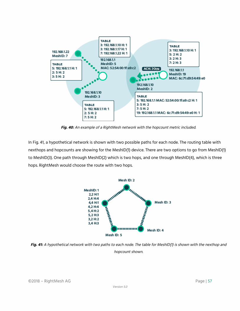
Fig. 40: An example of a RightMesh network with the hopcount metric included.
In Fig. 41, a hypothetical network is shown with two possible paths for each node. The routing table with
nexthops and hopcounts are showing for the MeshID(1) device. There are two options to go from MeshID(1)
to MeshID(3). One path through MeshID(2) which is two hops, and one through MeshID(4), which is three
hops. RightMesh would choose the route with two hops.
Fig. 41: A hypothetical network with two paths to each node. The table for MeshID(1) is shown with the nexthop and
hopcount shown.
©2018 – RightMesh AG Page | 57 Version 5.0

We recognize this is a naive approach; however, our aim was for bare minimal proof of concept at this stage.
It is possible to take into account the underlying link types, delay and capacity constraints, signal strength,
and many other factors. This type of optimization is well understood by the networking community and will
improve over time.
Data Transmission Combined with the routing layer and the one-hop connectivity layer, multipath end-to-end reliable
communication forms a really unique and valuable part of the RightMesh solution. This is what distinguishes
RightMesh from most of its competition. There are a few ways communication typically occurs in mobile
meshes:
1) Broadcast to everyone (either using UDP + existing broadcast / multicast approaches, or TCP on a
link by link basis - no end-to-end capability)
2) Single-path end-to-end TCP (with many limitations as outlined below)
3) Best-effort UDP communications with no reliability
Many existing mesh approaches simply make use of existing TCP to provide end-to-end connectivity.
However, TCP is not well suited to a mobile mesh network for several reasons:
1. Unless rooted, mobile phones do not let the user customize the version of TCP being used.
2. Mobile mesh networks are made of devices that frequently connect and disconnect. When this
occurs, a TCP connection would require end-to-end reestablishment of a connection, with a 3-way
handshake.
3. With IPv4 It is often impossible to make an end-to-end TCP connection because the IP address in
one hotspot means nothing to the neighbours three hotspots away. As such, there is no mechanism
to exchange this information between hotspots and have the routing automatically work. In this
case, it may be possible to have TCP on each single-hop link, but there are still the same drawbacks
from some of the other bullet points to be aware of. In the case of performing TCP on each link,
there is still no mechanism to prevent an entire end-to-end path from being saturated with traffic
(the congestion control will only work on a link-by-link basis, leaving the queues at the intermediary
nodes to potentially overload).
4. TCP often gets interference and congestion mixed up. It may start a backoff unnecessarily thinking
that congestion is occurring when it is temporarily poor network conditions due to external factors
©2018 – RightMesh AG Page | 58 Version 5.0
(e.g., a vehicle driving through the path of the signal, a microwave being turned on, a tree being
between two people who are moving, etc.).
5. The TCP on most non-rooted phones cannot handle multiple paths. This means even if your device
has a Bluetooth, Wi-Fi, and Wi-Fi Direct connection available, it is only able to use a single one of
them for one data stream. This also applies to Internet connections out of the mesh as well. There are
existing versions of TCP that can do this, notably mTCP; however, it is almost never included in
commercial phones.
RightMesh uses a combination of end-to-end acknowledgements and one-hop acknowledgements built on
top of UDP in order to ensure reliable data transmission. This protocol is based on mTCP and LTP. Since we
have implemented our own data transmission protocol, it is possible to split a datastream and send part of it
on one path, and part of it on another path, and then have the receiver recombine the packets in the correct
order. This would allow higher throughput than any one of the paths might obtain on its own. It is also
possible to operate in redundant mode where rather than split the traffic among the links, it is sent across
multiple links at the same time.
Keep in mind how the RightMesh packets work. There are DATA packets and DATA_ACK packets. There are
also ACK: DATA and ACK: DATA_ACK packets. The ACK packets are one-hop ACKs and the DATA_ACK is an
end-to-end ACK packet. There are also single-hop ACKs for the DATA_ACK packet, so the end-to-end ACK is
not lost.
Originally, in the proof-of-concept phase, every packet had both a single-hop ACK and an end-to-end (e2e)
ACK. This worked reliably; however, the throughput was very low. It was also low because the original
protocol waited for the e2e ACK before proceeding to the next packet. We have since improved this
protocol in two ways—both based off of lessons learned in traditional TCP.
First, we used sliding windows. We start with a single packet being transmitted. When the e2e ACK is
received, this doubles. The next transmision time, two packets are sent. When these two packets are
successfully received, four packets are sent in the next transmission, and so on. On the receiver side, e2e
ACKs are sent for batches of packets as well and not for every single packet. The ACK specifies the next
expected packet. If some packets are received with a missing packet between, the missing packet can be
filled in, and then an ACK is sent for the entire group of contiguous packets.
©2018 – RightMesh AG Page | 59 Version 5.0

Secondly, there is an adjustable timeout mechanism for backing off when the link becomes congested,
similar to TCP.
©2018 – RightMesh AG Page | 60 Version 5.0
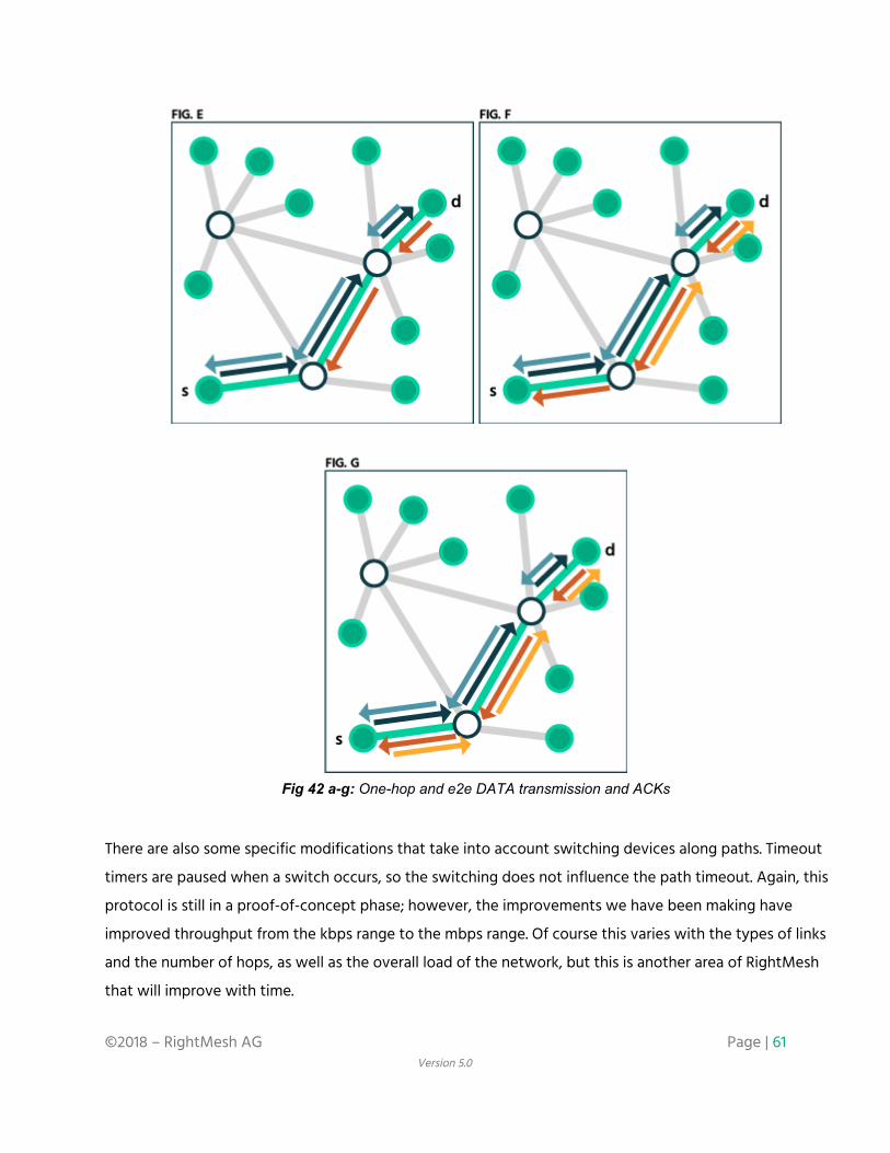
Fig 42 a-g: One-hop and e2e DATA transmission and ACKs
There are also some specific modifications that take into account switching devices along paths. Timeout
timers are paused when a switch occurs, so the switching does not influence the path timeout. Again, this
protocol is still in a proof-of-concept phase; however, the improvements we have been making have
improved throughput from the kbps range to the mbps range. Of course this varies with the types of links
and the number of hops, as well as the overall load of the network, but this is another area of RightMesh
that will improve with time.
©2018 – RightMesh AG Page | 61 Version 5.0

Encryption
Rightmesh supports end-to-end encryption using the Open Whisper/Signal library (whispersystems.org). The
default library involves a server portion which requires Internet access, so we have modified the library to
remove it. RightMesh offer two levels of security: one where the key is directly exchanged in one hop (this is
the more secure option). The second, where the key exchange occurs through the mesh over several hops, is
less secure because it may be subject to a man-in-the-middle attack.
RightMesh does not store any keys in any server, so any key exchange that occurs securely means only the
recipients can decrypt the data. For the company, there is no way RightMesh can be compelled to give up
the keys because none are stored. We are working on ways to improve this process (e.g., sending the key
split up across multiple paths so that attackers would need to compromise many devices at the same time).
We are also working on ways to improve the user-friendliness of a secure key exchange such as with a 2-D
barcode or NFC. Compared to other mesh platforms which broadcast to every device, RightMesh only
forwards directly on a routing path. As as result, fewer devices have data flowing through them, making it
much harder to attack.
Local Multicasting and Broadcasting
There are some competing mobile mesh technologies which take the strategy that it is too difficult to
maintain any end-to-end connectivity across multiple hops and aim for more of an opportunistic one-hop
p2p technology (and then call it a mesh). It is our view this is less of a mesh and more of a delay tolerant
network (DTN). Even among those which do attempt some form of end-to-end connectivity, some take the
strategy of broadcasting all data around the network. As mentioned in the routing section, and with the help
of the topology discovery protocol, RightMesh is able to compute paths to delivery data through specific
devices along the path, rather than a broadcast approach. It is our belief that this will enable RightMesh to
be a much more scalable mesh than these types of competitors since broadcasting with only a few devices
can quickly overwhelm the capacity available.
©2018 – RightMesh AG Page | 62 Version 5.0

Fig. 43: broadcast, unicast and multicast
That being said, RightMesh can support more efficient multicasting and broadcasting in addition to the
typical unicast operation that is the default transmission style. Similar to IP multicasting, RightMesh
multicasting works by devices joining a multicast group. This allows RightMesh to construct a minimum
spanning tree of all of the devices in a group while ensuring the minimum number of unicast transmissions
are performed in order to reach all of the devices in the tree, rather than unicasting one-by-one to each
member of the group. Fig. 43 shows visually the three different approaches and how the links are used in
each of the cases.
4. The Global RightMesh Network This section will be somewhat briefer than the local connectivity section, but it is not because this is less
well developed. Most of the principles that apply to the local connectivity also apply in the global context as
well. This section will be used to highlight the key differences and innovations on top of the local
connectivity that allow RightMesh to link together two separate meshes across the Internet. The reason for
doing this is for a couple of reasons. First, it is unlikely that a mesh across the entire world would scale
without involving some infrastructure, particularly at this early stage. There is likely some magic number of
hops that a local mesh can support well, and beyond that, we must use existing infrastructure to offset it.
Furthermore, in many places—particularly at launch of RightMesh—the density of devices will not support
very large meshes. In order to provide some expectation of how people are used to apps working, it should
©2018 – RightMesh AG Page | 63 Version 5.0
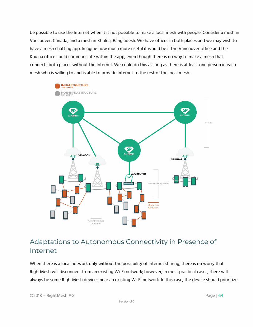
be possible to use the Internet when it is not possible to make a local mesh with people. Consider a mesh in
Vancouver, Canada, and a mesh in Khulna, Bangladesh. We have offices in both places and we may wish to
have a mesh chatting app. Imagine how much more useful it would be if the Vancouver office and the
Khulna office could communicate within the app, even though there is no way to make a mesh that
connects both places without the Internet. We could do this as long as there is at least one person in each
mesh who is willing to and is able to provide Internet to the rest of the local mesh.
Adaptations to Autonomous Connectivity in Presence of Internet
When there is a local network only without the possibility of Internet sharing, there is no worry that
RightMesh will disconnect from an existing Wi-Fi network; however, in most practical cases, there will
always be some RightMesh devices near an existing Wi-Fi network. In this case, the device should prioritize
©2018 – RightMesh AG Page | 64 Version 5.0

being connected to the Internet with its Wi-Fi connection. This would mean that the Internet sharing device
would only be able to act as a Wi-Fi direct MASTER or a Bluetooth device in order to still participate in the
mesh. It would be left up to the user of the device to decide whether or not they would like to actually
share their Internet data into the mesh. Even if they did not choose to do so, the device would still be able
to maintain an Internet connection and a mesh connection at the same time.
NAT / Firewall Hole Punching
There are often difficulties when trying to connect phones that may share the same Wi-Fi router (using
Network Address Translation [NAT]) or that may be on a cellular network which is often firewalled. Cellular
companies typically block the phones from listening for any incoming connection. They only allow a
connection to be made in reverse of the outgoing connection. For example, suppose you make an outgoing
UDP connection to port 5000. It will also open a random high-numbered port to receive a response on. This
will function from behind the firewall; however, if you tried to listen directly on port 5000, it would be
blocked from receiving anything incoming. Similarly with NAT, there may be the case that both phones are
trying to listen on the same port. They would also have the same external IP address, so it would be
impossible for both to listen to the same port externally. This would prevent any direct connections to both
of them from the outside. This is a well-known problem that has been solved previously by video game
companies, chat apps, voice and video communication apps, p2p systems, and many other Internet services.
The way in which we get around these difficulties is with a set of nodes which we classify as Superpeers.
These nodes are also running RightMesh, but do so with reliable, stable Internet connections where they
have the control to make sure the correct ports are open and available. These Superpeer nodes facilitate the
linking of separate meshes by acting as a forwarder between the meshes. These Superpeer nodes keep track
of the random, high-numbered port that gets assigned by the operating system of the phones with Internet
connections. It performs the mapping of these pairs (port, external IP address) to MeshIDs, so separate
meshes know how to reach each other.
Internet Routing vs Local Routing
The biggest change between Internet routing and local routing is extra paths to be maintained. This changes
the routing table and the discovery protocol slightly. There is a new boolean field that gets added to the
discovery process for peers that indicates whether a peer provides Internet or not. Internet routing still
©2018 – RightMesh AG Page | 65 Version 5.0

generally takes the lowest-hop count metric the same way local routing does; however, there are some user
preferences that are possible as well. The user may prefer to always use local routing, despite having a
lower-hop count Internet route available. They may choose to use the Internet despite having a shorter local
path available. Or they may choose the balanced approach which is the lowest-hop count—either Internet
or local. Finally, the user may wish to never use the Internet and only use local routing. These preferences
may be set by the user in the RightMesh settings which are packaged in the RightMesh service (Fig. 44).
These preferences would affect the behaviour of all apps running with RightMesh. Initially, there is no
app-level granularity for behaviour when it comes to routing.
Fig 44: The bottom of the wallet settings allows setting the routing preferences
Another change to the routing involving the Internet is the addition of this pair (port, external IP address) to
the routing table in the Superpeer layer. Rather than just routing towards the IP address of the Internet
Sharing Devices, the Superpeer must also account for the random high port that gets assigned in the case
that several Internet-connected devices exist behind the same NAT.
Additional Roles (GATEWAY, SUPERPEER)
There are two additional roles that appear in the routing table with the addition of Internet sharing. The
GATEWAY role is assigned to devices when they have—and are willing to provide—Internet access to other
©2018 – RightMesh AG Page | 66 Version 5.0

peers in the mesh. When making routing decisions towards separate meshes through the Internet, the
RightMesh library looks for routes towards gateways. There may be multiple GATEWAYs which lead towards
a single or many SUPERPEERs.
The SUPERPEER role is assigned to devices which provide the hole punching and forwarding capabilities to
other devices in the mesh. SUPERPEERs are currently used to determine how to route traffic to another
connected mesh. They contain the routing next-hop entries (random high port, IP address, MeshID) mapping.
The RightMesh library running on a device within the mesh would need to discover at least one GATEWAY
and one SUPERPEER in order to relay traffic to another mesh.
Additional Packet Types (INFO)
INFO packets are used to convey topology information to Superpeers. Any device which is directly
connected to the Internet sends these packets to help with the hole-punching capabilities. By periodically
sending these packets, it maintains the open state on firewall / NAT for the return direction of the UDP
packets.
INFO packets are also sent from any device sending JOIN packets (joining two or more separate sections of
mesh together). By having these devices—which are key links between connected “islands”—relaying local
topology information to the superpeers, they can make a logical connectivity graph that allows for routing
optimizations to occur. This also allows us to debug and troubleshoot bottlenecks and connectivity
problems more easily.
Relaying / Caching Behaviour
It is also possible for app developers to provide their own SUPERPEERs. These are special RightMesh Java
apps which run on a computer (or cloud instance) which has reliable, consistent, and fast Internet access. In
this scenario, the app superpeer would act as a trusted device that has been trusted only by the app which
is making use of it. For instance, an app which allows people to play geocaching may also deploy a
geocaching superpeer. While the app lets people discover geocaching locations, where the location is
actually a remote sensor, which relays data into the mesh eventually towards the geocaching superpeer,
where the data may be stored and presented on normal traditional websites. This “data-mule” behaviour is
demonstrated in Figure 45.
©2018 – RightMesh AG Page | 67 Version 5.0

The app superpeer would be able to provide some further infrastructure needs that a normal mesh app
could not provide. For instance, consider a mesh app where there are remote sensors, but in a location
where people occasionally pass (e.g., in the mountains or in northern Canada). An app superpeer would be
used as a collection point where the data would be stored for visualization, analysis, etc., and the RightMesh
library would handle routing, despite the phones not always being connected to the Internet. In our remote
sensor example, as a hiker passes by, it would forward the collected data the next time the phone had a
connection to the app superpeer through RightMesh automatically.
Fig 45: An example of a data mule application where an out of range sensor uses mobility patterns and caching to relay
data to an app SUPERPEER
Internet Multicasting and Broadcasting Some interesting possible applications emerge when it comes to Internet-connected RightMesh devices,
particularly when involving the Superpeer layer. Consider a device which is running the RightMesh superpeer
layer on an Amazon instance. This device would be partly to support linking RightMesh meshes together and
forwarding packets. It could also be running a traditional web server, database server, and other more
typically centralized architecture. Suppose this device runs a web service that allows large corporations to
push advertisements out to people on apps running on RightMesh.
©2018 – RightMesh AG Page | 68 Version 5.0
5. Blockchain/Token Integration While there have been some technologically strong mesh networks, and even some mobile mesh network
frameworks which may prove to be great solutions, there are none which are both technologically strong
and provide incentives to users to participate in the network. A user with a monthly data plan may be
paying $50 per month for their data, so why would she share it into the mesh for free? Similarly, why should
other users leave their Wi-Fi, Wi-Fi direct, and Bluetooth on and connected to other people? Why should
people use their battery faster to participate in this network?
Today, we all have grown to trust that ISPs will charge us the correct amount of money for the data we
consume; however, there is no real transparent process which lets us see on a granular basis how much data
we have consumed from where. Pricing structures are also quite unclear, particularly when roaming, causing
some countries and regions to issue maximum fee limits in regulations, or even banning roaming fees all
together to prevent consumer gouging.
Any successful mobile mesh should combine strong mobile mesh technology with an ability to support
incentives for the network users, providing services critical to the function of the network. This cannot be
accomplished with a centralized solution. Otherwise, it risks becoming just another ISP. To fully realize the
decentralized vision of a mobile mesh network, it is required that the incentives must be built using
decentralized technology.
The RightMesh Token (RMESH)
RightMesh chose to build its RMESH token on top of the Ethereum blockchain, and it is an ERC-20
compatible token. From a technical perspective, while one could use another ERC-20 token within the
RightMesh ecosystem, we believed it essential to the user experience of people using the mesh that the
payment currency being used to incentivize the technology would be valued based on its utility to perform
mesh related tasks.
For instance, suppose someone is using Ethereum to purchase data on the mesh. The value of Ethereum may
fluctuate widely during the process of actually consuming the data, so it is very difficult for users to want to
spend their Ethereum to purchase data. Ethereum’s value is tied to greatly different ideas than those of a
mesh network. Ethereum values being able to facilitate and settle transactions, to support some level of
©2018 – RightMesh AG Page | 69 Version 5.0
general purpose computation, and some basic messaging with its whisper features. However, it does not
consider devices which are remote or intermittently connected particularly well. It doesn’t value energy
expended relaying data through a network, it doesn’t value the price of data geographically, it doesn’t value
the storage price of a cache on a phone, or it doesn’t consider the mobility of a user to transport digital
goods to a remote community without reliable internet access. A mesh token would have value tied to all of
these factors: the utility of the token within the mesh.
Payment Channels
Similar to “Bitcoin + Lightning”, “Ethereum + Raiden” is the comparable micropayment channel solution.
Raiden lets two parties set up a channel using the smart contract mechanism in Ethereum whereby two
parties create a channel with an initial balance on each side of the channel. As transactions occur, rather
than executing the contract, each party exchanges signed transactions, so either party can use these
signatures with the agreed upon updated channel balance to close the channel at any point in time in the
future. If one party tries to cheat the other, it is possible to produce the signed transaction proving the other
party was lying resulting in penalties for the liar. There are still some technical challenges to be solved in the
mesh network case, particularly when devices become disconnected from the Internet when a channel is
being closed; however, there are solutions such as third-party observer services which can mitigate these
risks.
There are some criticisms of Ethereum + “Lightning-like” networks like Raiden, but this is a misunderstanding
of how to design these solutions. In the example of an AirBnB or Uber running on Ethereum + Raiden, the
customers would establish a payment channel between themself and the decentralized organization, which
would act like a payment hub. You would then load Ether or Tokens into the payment channel, sort of like a
gift card. This would be the only transaction. You could conceivably pay for rides many times before you had
to reload. All of this could occur without the channel being closed. The driver would only close their channel
when they want to extract Ether or tokens — maybe once a month like a pay cheque — or less often if
they wanted to conserve the fees.
In the RightMesh case, you can have many, many transactions occurring in the channel. When a buyer of
data runs out of tokens in the channel it is fairly cheap (compared to re-establishing a channel) to reload the
existing channel. The only person motivated to close is the seller; however, there may be creative solutions
to avoid channel closing even on the seller side.
©2018 – RightMesh AG Page | 70 Version 5.0
RightMesh Token Incentivization System Architecture
Managing limited resources is a known hurdle for RightMesh, whether in regards to battery life, network
capacity, or memory and storage limits. Because of these constraints, it is currently not feasible to run a full
crypto node on the mobile phone itself.
Since devices on RightMesh have an identification based on an Ethereum account (including the private and
public key), using the Ethereum-j library, it is possible to generate signed transactions from the account and
pass them through RightMesh to devices reliably and permanently connected to the Ethereum network. We
call these devices token SUPERPEERs since these devices are running both the RightMesh library and
providing the SUPERPEER layer, and running the the full Ethereum node which enables our Token to operate
(or at least are passing the transaction from the mesh to another Ethereum node using IP networks). The
benefit of this is that none of the RightMesh devices need to worry about finding the Ethereum network
from within the mesh. It is built into the discovery protocol. SUPERPEERs will just appear in the routing table
within the library. App developers do not need to even know of the existence of any of this: they only deal
with peers, whether they are local, or across the Internet. The reason we distinguish the token SUPERPEERs
is because it is also possible to have devices which run the SUPERPEER functions of hole-punching and
internet relaying without providing incentivization.
©2018 – RightMesh AG Page | 71 Version 5.0
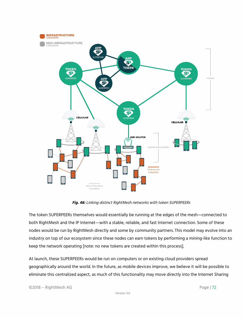
Fig. 46: Linking distinct RightMesh networks with token SUPERPEERs
The token SUPERPEERs themselves would essentially be running at the edges of the mesh—connected to
both RightMesh and the IP Internet—with a stable, reliable, and fast Internet connection. Some of these
nodes would be run by RightMesh directly and some by community partners. This model may evolve into an
industry on top of our ecosystem since these nodes can earn tokens by performing a mining-like function to
keep the network operating [note: no new tokens are created within this process].
At launch, these SUPERPEERs would be run on computers or on existing cloud providers spread
geographically around the world. In the future, as mobile devices improve, we believe it will be possible to
eliminate this centralized aspect, as much of this functionality may move directly into the Internet Sharing
©2018 – RightMesh AG Page | 72 Version 5.0
Devices themselves. At present, the biggest limitation is hardware, as it is not feasible for phones to act as
full Ethereum nodes. The SUPERPEER functions as a a hole-punching aid, a translator between the IP-based
Internet and our mesh protocols, and an Ethereum full-node.
When the SUPERPEER recognizes that a remotely signed transaction is being passed to it, the SUPERPEER
executes the transaction on its local geth instance and waits for the confirmation. It then passes the result
back to the device in the network which executed the transaction. This means that any device within a
RightMesh network is able to send an ERC-20 compatible token to another device, query its own token
balance, and execute contracts on the Ethereum network from potentially many hops away from the
Internet. At best, as far as we know, thin clients exist on mobile phones which can perform similar
capabilities when the device is connected to the Internet directly. However, nothing exists that allows for
cryptocurrency transactions from outside of the range of traditional IP-based Internet access.
All of the code that for micropayment channels using microRaiden and Ethereum have been open sourced
(along with any contracts), so that the community can verify and improve upon the stability of the platform
and to encourage the users to trust that things are operating correctly. RightMesh has also open sourced
some of its own created apps to demonstrate possible implementations of the Mesh SDK:
https://github.com/RightMesh. The company will explore open sourcing its core mesh technology once the
network becomes hardened and the network established.
From a developer's perspective, they simply need to define the transaction they wish to make within their
RightMesh application, and issue a call to our library. RightMesh will perform the transaction signing and
optimize how to route the packet out of the mesh and into the Ethereum network. The full Ethereum node
at the edge of the mesh is also running a Java version of our library. It uses the local remote procedure call
(RPC) mechanisms to relay the transaction to a locally-running Geth client. The Geth client verifies the
transaction and executes it. The result of the verification and execution will then be relayed back to the
mesh node which originated the transaction. Using a similar approach, RightMesh could adapt to support
other cryptocurrencies as well, such as Bitcoin.
©2018 – RightMesh AG Page | 73 Version 5.0

Fig. 47: RightMesh Token Incentivization System Architecture
Fig. 47 shows four distinct local RightMesh networks with two participating token SUPERPEERs. There could
also be non-token SUPERPEERs involved - which we call “app” SUPERPEERs, however, we have left them out
of this figure for simplicity. In this figure, the left SUPERPEER has two geographically separate meshes
attached to it while the right SUPERPEER has two different geographically separate meshes attached to it.
The SUPERPEERs may be deployed all around the world, similar to how AWS instances are deployed in
different places based on geography and demand. The left superpeer may be deployed in Canada, and have
a mesh in Vancouver and a mesh in Toronto, while the right SUPERPEER may be deployed in Bangladesh and
have a mesh in Dhaka and a mesh in Khulna. The green line represents a fast internet connection between
the two SUPERPEERs. This is important because in the initial implementation, the data will be relayed
directly between the superpeers to reach the farther meshes. In addition, the SUPERPEERs are running full
Ethereum nodes. On the Ethereum network, the two token SUPERPEERs may also be peers of each other. In
addition, there may be many public peers on the Ethereum network.
RightMesh Token Incentivization System Implementation Now that the architecture has been outlined, the remainder of this section will focus on specific changes to
support the functioning implementation. This includes additional roles, changes to the discovery protocol,
©2018 – RightMesh AG Page | 74 Version 5.0

the data transmission protocol, channel opening and closing, and also a short discussion on the reference
implementation of the token superpeer.
Additional Roles (SELLER, BUYER, RELAY) Some portion of the devices provide supply of resources (bandwidth, storage, processing, battery) to the
network. In the case of bandwidth for sharing data, these are the Internet sharing devices or SELLERs. In Fig.
48 and Fig. 49, these are the devices connected directly to the token superpeers. Devices which aid in
delivering the supply of resources to the consumers (BUYERs) are called forwarders or RELAYs. The BUYERs
may be scattered throughout the mesh, and at times they may be both BUYERs and RELAYs.
Fig. 48: The network topology we will consider as the simplest case
For the remainder of the discussion on RightMesh token channels, we will focus on a simple topology (Fig.
48) which shows a single SUPERPEER and two distinct mesh networks, each with one buyer and one seller.
We will not consider RELAYs initially; however, they would exist between the BUYER and SELLER. All peers
which are not on the SUPERPEER side of the network are called REMOTEPEERs for this discussion.
©2018 – RightMesh AG Page | 75 Version 5.0

Fig. 49: Simple BUYER / SELLER topology with payment channels for simplest case
Incentivization is currently possible when a device wants to send traffic from one separate mesh to another
through the Internet Sharing Devices via the SUPERPEERs. In order to support this, RightMesh would need to
provide general purpose Internet functionality, which is on the roadmap for 2019 as previously mentioned. In
this case, a PROXY role would also be required which would be a new class of SUPERPEER. SUPERPEERs
would then be able to charge higher fees to provide more services. Mesh-to-mesh relaying could be a lower
fee than Mesh-to-Mesh and General Purpose activity.
Changes to the Mesh Discovery Protocol
One of the biggest changes to the discovery protocol is that extra fields which provide pricing details from
the Internet Sharing Devices (SELLERs) to the rest of the local mesh. This is set by users of the SELLER
devices. The user simply opens the settings for the RightMesh service and sets the price. This has the effect
of propagating this change to all devices in the local mesh. Similarly, potential BUYER devices can use the
same settings interface to set the maximum rate they are willing to purchase data for.
Fig. 50 shows the wallet built into the RightMesh service. This lets users set the price for which they are
willing to buy or sell data. This UI hooks into the discovery protocol, so when a user changes the price they
are willing to sell, it updates all other devices nearby. If data packets continue to arrive before the change
©2018 – RightMesh AG Page | 76 Version 5.0

has propagated, the SELLER device will be able to tell. This is because the data packets contain the balance
proof, and a signature indicates how much is being paid for the data that is about to be sent. If the BUYER
has not received the updated price yet, the packet will be dropped by the SELLER. By the time a re-transmit
occurs, the price should be updated in the BUYER device and operations will continue as normal. In order to
speed up this process, instead of dropping the packet, the SELLER could send a modified DATA_ACK packet
to the BUYER indicating that the price has changed. This would trigger a retransmit of the data immediately
with updated pricing attached to the data.
Fig. 50: Example of the Wallet functionality built into the RightMesh service.
©2018 – RightMesh AG Page | 77 Version 5.0

Channel Opening and Closing
In order for a payment to actually occur between nodes, payment channels must be established. RightMesh
makes use of the token SUPERPEERs acting as payment hubs. The reason for this is because if payment
channels were established between every device pairwise in the mesh, there would be more data flowing to
create and manage channels than there would be any real data. Furthermore, pairwise channels between all
possible nodes would be very sensitive to changes in topology which is common in a mobile mesh network.
A new type of packet, called GET_ALL, on top of the reliable data transmission has been created to help
with establishment and closing of payment channels. When a REMOTEPEER device discovers a token
SUPERPEER in its local mesh for the first time, it sends out this GET_ALL packet which is relayed to the token
SUPERPEER. The token SUPERPEER then queries the payment channel smart contract to determine if an
outgoing channel from the SUPERPEER and REMOTEPEER exists. If one does not exist, the SUPERPEER
creates one. This part requires no remote transactions from the REMOTEPEER side, just the MeshID. It also
checks if an incoming channel exists from the REMOTEPEER to the SUPERPEER.
In the response, the SUPERPEER returns whether the channel exists from the REMOTEPEER to the
SUPERPEER, the RightMesh Token balance of both of the channels and the Ethereum balance of the MeshID.
The REMOTEPEER will examine the response, and if the channel does not exist from the REMOTEPEER to the
SUPERPEER, the REMOTEPEER will prepare a follow-up packet with two signed transactions: one approving
funding of a new channel, and one for creation of the channel.
The first transaction is to approve the payment channel smart contract to transfer a number of tokens from
remote peer's account. This will be the deposit amount. The function called in the first transaction is defined
in ERC-20 RightMesh token smart contract. The second transaction is to create a payment channel. The
function called in the second transaction is defined in payment channel smart contract (based off of micro
Raiden).
Generally speaking, after a unidirectional payment channel is created, either payer (token sender) or payee
(token receiver) can close the payment channel as long as one has both the balance-proof and closing-hash
signatures created with a same balance. After closing the channel, the balance amount of token will be sent
to the payee's account. The rest of the tokens not yet spent by the payer will be reimbursed to the payer.
©2018 – RightMesh AG Page | 78 Version 5.0
Changes to the Data Transmission Protocol for Data Accounting
The data transmission protocol depends on a Raiden micropayment channel being established from the
BUYER device and the token SUPERPEER. Similarly, for a SELLER we assume a channel has been established
from the token SUPERPEER to the SELLER. As part of the packetization and routing process, the RightMesh
library is able to compute the price of each packet from BUYER to the SUPERPEER based on the cost of the
route set by the SELLER.
The balance-proof is a signature signed/created by the payer. The closing-hash is signed/created by the
payee. So, to enable the above the functionality, we include balance-proof and/or closing-hash in the packet
header of DATA and DATA_ACK packet.
Consider again the topology outlined in Fig. 48 and Fig. 49, the simplest case for data transmission and
tokens. Buyer1 and Buyer2 wish to communicate over a long distance and they do not have cellular network
or WiFi. As such, they would like to communicate over the Internet by using RightMesh service. Each remote
peer is a buyer buying Internet data from a seller (the gateway peers who have Internet access) on each
side. Without loss of generality, we assume buyer1 acquires data from seller1 and buyer2 acquires data from
seller2. Both seller1 and seller2 can access a superpeer in the middle.
Unidirectional payments are created as follows:
● From buyer1 to SUPERPEER
● From SUPERPEER to seller1
● From buyer2 to superpeer
● From SUPERPEER to seller2
Now, assume buyer1 is sending an Internet data packet to buyer2. The library will first check if the
aforementioned payment channels are ready to use. If not, the channels have to be created first.
Then, as shown in Fig. 51, according to the data selling price of seller1 listed in the routing table (e.g., 2 tokens
per byte), buyer1 will sign the first balance-proof signature (BPS) and add the signature in the packet header
(purple signature in Fig. 51). Buyer1 will save the balance and BPS in a table at its memory. This BPS is used to
pay the superpeer. When seller1 receives the packet from buyer1, since it knows that it is a seller and get
paid by superpeer, so seller1 will add a closing-hash signature (CHS), the left yellow signature in Fig. 51, to
©2018 – RightMesh AG Page | 79 Version 5.0

acknowledge the previous BPS received from superpeer. As we are transmitting the first packet, and the
superpeer has not paid seller1 before, the CHS is with zero balance. The target of the CHS, signed by seller1,
is the superpeer.
Fig. 51: Balance proof signatures being attached to DATA and DATA_ACK packets
In Fig. 51, when the superpeer receives the DATA packet, it finds out first if there are BPS from buyer1 and
the CHS from seller1 sending to it. The superpeer takes out both signatures from the packet header and
saves/updates corresponding signatures in the table. Whenever a BPS is received by the payee, the CHS will
be created by the payee automatically. In our situation, the superpeer receives the BPS from buyer1, so a
CHS is created/signed by the superpeer. The CHS will not send back to buyer1 immediately. It will be added
in the packet header of DATA_ACK when the acknowledge is sent from buyer2 to buyer1. We are going to
revisit this part later.
The superpeer is responsible to forward the packet to its destination (buyer2). Note that the BPS and CHS
from buyer1 and seller1 have been removed from the packet header. Now, the superpeer needs to include a
©2018 – RightMesh AG Page | 80 Version 5.0

new BPS to pay seller2 (the right yellow signature in Fig. 51) and a new CHS (blue signature in Fig. 51) to
acknowledge the payment sent by buyer2 along with the previous packets. Since we are delivering the first
DATA, the CHS to buyer2 has a balance equal to zero. The balance in the BPS from superpeer to seller2 is
calculated according to the data selling price of seller2 given by the routing table (e.g., 3 tokens per byte).
Both these signatures will also be saved in the table of the superpeer.
In Fig. 51, when the DATA packet reached seller2, the seller2 finds out if there is a BPS sending to it. Seller2
takes out the BPS. Seller2 creates/updates the CHS with respect to the superpeer, but it will not send the
CHS directly. The CHS will be contained in the header of DATA_ACK (we are going to revisit this later).
Seller2 continually forwards the DATA packet to buyer2. Note that CHS is signed by the superpeer to
acknowledge the payment from buyer2 to superpeer is still in the packet header. When the DATA packet
eventually reaches buyer2, buyer2 takes out the CHS (which has zero-balance since buyer2 has never paid
superpeer before) and updates it in its table.
Fig. 52: Balance proof signatures being attached to DATA and DATA_ACK packets
According to the size of DATA packet received and the data selling price of seller2 from routing table,
buyer2 creates BPS to pay for superpeer. As shown in Fig. 52, the BPS (blue signature in Fig. 52) will be
©2018 – RightMesh AG Page | 81 Version 5.0

included in the header of DATA_ACK sending back to buyer1. The created BPS for the payment channel from
buyer2 to superpeer will be saved in the table at buyer2.
When DATA_ACK reaches seller2, the seller2 will first add its CHS (created upon the DATA reception from
superpeer previously, the yellow signature at right of Fig. 52) in the DATA_ACK header, then forward the
DATA_ACK to the superpeer.
In Fig. 52, the superpeer takes out the BPS sent by buyer2 and the CHS sent by seller1. Both signatures are
logged or used to update the existing entries. The superpeer also creates a CHS to acknowledge the
received BPS for the payment channel from buyer2 to superpeer and keeps that in its memory. These two
signatures are removed and replaced by two new signatures: one is the BPS to pay for seller1 (the left yellow
signature, created upon the DATA reception from seller1 previously) ; one is the CHS to acknowledge the
BPS received from buyer1 (the purple signature, superpeer had created the closing-hash when it received
the DATA packet). The DATA_ACK is then forwarded to seller1.
Seller1 receives DATA_ACK and finds out there is a BPS sending to it. It takes the BPS out (the left yellow
signature in Fig. 52) and saves it in the memory for the payment channel from superpeer to seller1. Seller1
creates a CHS to acknowledge the BPS, and holds it in the memory for now. Seller1 then forwards the
DATA_ACK towards buyer1.
Buyer1 receives DATA_ACK and knows that DATA packet has been successfully sent. Buyer1 finds that there
is a CHS (purple signature in Fig. 52) sent from superpeer which acknowledges the BPS sent along with the
previous DATA. The CHS is logged and used to update the existing one in its memory.
It is worth mentioning that:
1. The BPS from superpeer to seller1 was received by seller1 and a corresponding CHS was created, but
the CHS had not yet sent it back to the superpeer.
2. The BPS from buyer2 to superpeer was received by the superpeer and a corresponding CHS was
created, but the CHS has not yet sent it back to buyer2.
These two signatures will be added in the packet header of the next DATA packet from buyer1 to buyer2.
©2018 – RightMesh AG Page | 82 Version 5.0
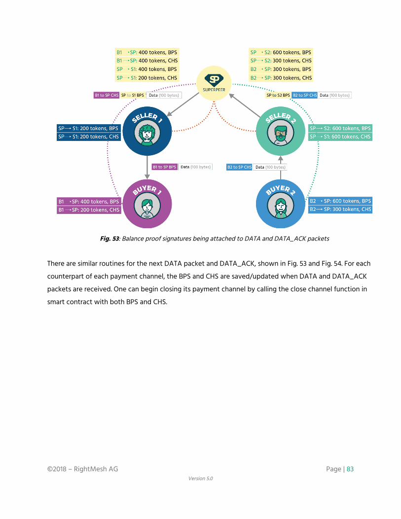
Fig. 53: Balance proof signatures being attached to DATA and DATA_ACK packets
There are similar routines for the next DATA packet and DATA_ACK, shown in Fig. 53 and Fig. 54. For each
counterpart of each payment channel, the BPS and CHS are saved/updated when DATA and DATA_ACK
packets are received. One can begin closing its payment channel by calling the close channel function in
smart contract with both BPS and CHS.
©2018 – RightMesh AG Page | 83 Version 5.0
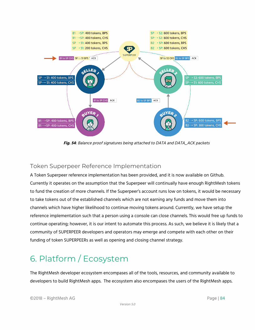
Fig. 54: Balance proof signatures being attached to DATA and DATA_ACK packets
Token Superpeer Reference Implementation A Token Superpeer reference implementation has been provided, and it is now available on Github.
Currently it operates on the assumption that the Superpeer will continually have enough RightMesh tokens
to fund the creation of more channels. If the Superpeer’s account runs low on tokens, it would be necessary
to take tokens out of the established channels which are not earning any funds and move them into
channels which have higher likelihood to continue moving tokens around. Currently, we have setup the
reference implementation such that a person using a console can close channels. This would free up funds to
continue operating; however, it is our intent to automate this process. As such, we believe it is likely that a
community of SUPERPEER developers and operators may emerge and compete with each other on their
funding of token SUPERPEERs as well as opening and closing channel strategy.
6. Platform / Ecosystem The RightMesh developer ecosystem encompases all of the tools, resources, and community available to
developers to build RightMesh apps. The ecosystem also encompases the users of the RightMesh apps.
©2018 – RightMesh AG Page | 84 Version 5.0

Furthermore, the ecosystem includes parties operating key pieces of the RightMesh network: the people
acting as SELLERs, SUPERPEERs, and RELAYs. Finally, the ecosystem contains partnerships with people
building out particular components of the RightMesh architecture.
The place where developers should start is within the developers’ portal. This is the place where developers
can sign up for an account and obtain app keys. App keys will help the RightMesh team map bug reports,
crashes, performance issues, and gather feedback and give support to the teams working on the RightMesh
apps. Once a developer has signed up for an account, they are able to access the Java API documentation, as
well as a reference section which describes some of the key pieces to building a RightMesh app.
Fig. 55: RightMesh Developers Portal
We have also built a growing repository of sample RightMesh apps on GitHub, including the usual “Hello
Mesh” app, but also a “ping” type of app called “Reflect”, a an app which shows of how data routing follows
a unicast path called “Ripple”, our reference implementation of a “token Superpeer” and a messaging app
called “MeshIM”. Our Bangladesh team has been developing an emergency app called “Flare” which is not
yet open source. MeshIM and Flare are the first apps which are moving towards becoming commercial apps,
while the others are mostly demonstration apps. This is just a small snapshot of what is possible within
RightMesh and we are working with key partners to build out further commercial and real-life applications
as well as innovating on applications that take advantage of the unique properties and capabilities that
RightMesh provides.
©2018 – RightMesh AG Page | 85 Version 5.0

Furthermore, the involvement of the Superpeer in RightMesh opens the door for many interesting
applications within the ecosystem. App developers could use it as the translation point between mesh apps
and non-mesh portions. Services to push content out to users could be created that are much more efficient
to the partners operating the services. For example, when someone wants to push out a 200MB video
advertisement to 1M people. Unless they are using IP multicasting, a single video may be sent 1M times x
200MB, which with simple math equates to 200TB of data. Integrating this “push” outwards with a
RightMesh superpeer, the push could occur more strategically (perhaps once per mesh) dramatically
lowering the amount of data required. The bandwidth costs of the push is significantly lowered, and the
efficiency of the Internet links are significantly improved.
Similarly in the opposite direction, similar gains can be made by collecting up sensor readings, aggregating
the results at local superpeers and then pushing them out onto the Internet strategically.
The last part of the RightMesh ecosystem is the opportunity to interoperate with many complimentary
distributed systems. There are several mesh initiatives that are more infrastructure and hardware focused
which are complementary to RightMesh, and even other mesh initiatives on mobile phones which may be
able to interoperate with RightMesh. The goal of all of these projects should be to free people from the
centralized infrastructure and corporations controlling it, and as such we should be strongly motivated to
work together.
While RightMesh users are pseudo-anonymous when they are acting as buyers and relays, they are less so
when they acting as sellers, where they may have public IP addresses. Partnering with systems such as
ORCHID Labs (Orchid Protocol) at the edges of the mesh would allow for devices to become anonymous in
mesh even at the edges.
When it comes to incentivizing resources, RightMesh currently focuses on incentives for data; however,
interoperability with decenctralized storage systems (e.g., Filecoin or Storj) may help with incentivizing
on-device caching and storage. Similarly, individuals can be incentivized for on-device processing (Golem) or
on-device data/sensor information (SingularityNET).
©2018 – RightMesh AG Page | 86 Version 5.0

7. Future Technical Roadmap While there are details and hints at our roadmap scattered through this document, this section collects the
most important milestones and future roadmap elements to come in one spot, so that readers can
understand clearly what has been built, what will be built, and what needs to be fleshed out.
Users are encouraged to read the full product roadmap in the RightMesh White Paper for additional details
on our roadmap approach and lifecycle stages.
What Works Today:
As of March, 2018, RightMesh has a basic mesh networking platform developed for Android devices. The
platform as it stands now is a library that supports multihop connectivity between many devices (we have
had up to 30 so far on a single mesh) and can cover long distances (we have achieved about 1000 feet with
only 5 devices. We will need to do further experimentation to cover longer distances). We have done initial
pilot projects and tests in Rigolet, Labrador in Northern Canada, as well as tests with our team in
Bangladesh, and in Vancouver, Canada.
There are several sample apps available on our public GitHub repository: https://github.com/RightMesh
including a “hello mesh” app which gives an introduction to developers, a colour changing demo that
illustrates how our library forms routes compared to the broadcasting libraries, a “ping test” type of app
which is good for coverage testing, and soon there will be a simple “hello Java” app which shows the same
type of code running on a something like a personal computer, Raspberry Pi, or other device running Java.
The mesh portion of the library is becoming quite mature. The connectivity aspect supports Wi-Fi, Wi-Fi
Direct, and Bluetooth and has two provisional patents covering it. A third patent has also been filed. It is
partially autonomous right now, in that once the user selects which technologies to enable and which role
they wish to be in (hotspot, switching, or client) the network will self form. We are working on what we call
“fully autonomous” mode where the library can figure out the best mixture of these roles and technologies
to enable.
©2018 – RightMesh AG Page | 87 Version 5.0

We have put quite a lot of time into a Developer's Portal, so our library is easy to program with, and well
documented. This includes Javadocs, a step-by-step Getting Started Guide, and information about what to
include in Gradle. In the future, we intend to add more tools to support developers such as bug reporting
and collection from the RightMesh library automatically into the developer portal. We will also support
deploying test cases and performance stress testing directly from the developer portal, so developers can
determine if there app is causing a problem or if the mesh protocol is not performing correctly.
More recently, we have made great progress on the token incentivization. We can now automatically open
micropayment channels between devices when they first obtain an Internet connection, attach tokens to
data transfers, and close the token channel which effectively enables payments from one device to another
for bandwidth. This is operational on the Kovan testnet.
What is Next to Come:
The next major milestone on the mesh side is real performance analysis. While we don’t have official
performance numbers we can stand by yet, we have small scale evidence over a small number of hops that
we can achieve high performance (on the order of Mbps). It is our intent to obtain future performance
numbers using a scientifically rigorous process., As we go farther down this road, we will release further
apps that allow for throughput and delay measurement testing, so the community can try out the mesh and
perform their own tests to see where and how it works best.
Along with the performance analysis, it will be important to get a clear idea on how the network
performance changes as the network grows. Where are the bottlenecks, how does performance degrade
over hops, and how many Internet sharing devices can one superpeer support? How many consumers can
one internet sharing device support? Also, with <x> devices consuming data, how quickly will <y> data be
consumed? After we answer some of these questions, there will be lots of opportunities to improve the
performance as we will learn a significant amount about where the network is weak, while helping us
generate ideas on how to improve.
One of the biggest challenges for us on the network side is automated testing of the library. Given that
much of the operation of the library depends on complex connection topologies between groups of phones,
it is difficult to simulate effectively. There is some portion of the library that we have applied unit testing
and limited offline testing to; however, some of it requires real device testing as there are aspects that need
©2018 – RightMesh AG Page | 88 Version 5.0
to be tested that are specific to particular Android versions, the orientation of the phones near to each
other, and the order in which the devices discover each other. We would like to support phones from
Android 4.x to present; however, with the wide range of capabilities, the way Android handles permissions,
and other differences between devices, this means there is a huge scaling problem to automating the whole
process since the number of testing possibilities grows exponentially as the mesh size grows. We are looking
at ways to automate as a much of this as possible so future builds are stable across a wide range of devices.
Since acquiring Dr. Lucien Louiseau, who is an expert in delay tolerant networks, we will be working towards
adding some specific delay-tolerant APIs to RightMesh, so app developers can create apps with either
end-to-end transmission, delay-tolerant transmission, or both.
There is still more work to be done the incentivization side. Our current proof of concept supports a simple
topology; however, we would like to extend this to multiple superpeers, and provide tokens to relay devices
in between. We are almost at the state where the relay devices may be provided tokens, but are still a few
weeks away from supporting multiple superpeers. We also would like to put more concentrated thought
into the economics and incentive structures to ensure that tokens move around the system in a stable
manner. Once the basic data sharing incentive structure is in place and well understood, the next step will
be apps for ad and app distribution, “data mule” incentives, storage/caching, processing, and more.
We are also rapidly growing our team, and are on the lookout for more talent. We do not discriminate based
on location, nationality, religion, or sexual orientation, and have a culture based on an award winning
workplace culture. So if you have experience (either academic or professional), passion, and a commitment
to doing things right, we would appreciate hearing from you.
We welcome feedback via Git, Telegram, and more methods identified below.
©2018 – RightMesh AG Page | 89 Version 5.0

Additional Resources & Links
● RightMesh White Paper: https://www.rightmesh.com/whitepaper ● Website: https://www.rightmesh.io ● Developer Portal: https://www.rightmesh.io/developers/ ● Corporate Blog: https://www.rightmesh.io/news/ ● Twitter: https://twitter.com/Right_Mesh ● Telegram: https://telegram.me/RightMesh_Official ● GitHub: https://github.com/rightmesh ● Careers: https://www.left.io/careers
©2018 – RightMesh AG Page | 90 Version 5.0