technicalreview 1981-1
DESCRIPTION
The Fundamentals of Balancing MachinesBrüel & KjœlTechnical Review (Brüel & Kjœl)To advance Techniques in acoustical electrical and mechanical measurement1981 nro1TRANSCRIPT


PREVIOUSLY ISSUED NUMBERS OF , BRUEL & KJ/ER TECHNICAL REVIEW
T
4 - 1 9 8 0 Selection and Use of Microphones for Engine and Aircraft Noise Measurements.
3 -1980 Power Based Measurements of Sound Insulation. Acoustical Measurement of Auditory Tube Opening.
2 - 1 9 8 0 Zoom-FFT. 1-1980 Luminance Contrast Measurement. 4 - 1 9 7 9 Prepolarized Condenser Microphones for Measurement Pur
poses. Impulse Analysis using a Real-Time Digital Filter Analyzer.
3 -1979 The Rationale of Dynamic Balancing by Vibration Measurements. Interfacing Level Recorder Type 2306 to a Digital Computer.
2 -1979 Acoustic Emission. 1-1979 The Discrete Fourier Transform and FFT Analyzers. 4 - 1 9 7 8 Reverberation Process at Low Frequencies. 3 -1978 The Enigma of Sound Power Measurements at Low Frequen
cies. 2 -1978 The Application of the Narrow Band Spectrum Analyzer Type
2031 to the Analysis of Transient and Cyclic Phenomena. Measurement of Effective Bandwidth of Filters.
1 -1 978 Digital Filters and FFT Technique in Real-time Analysis. 4-1 977 General Accuracy of Sound Level Meter Measurements.
Low Impedance Microphone Calibrator and its Advantages. 3 -1977 Condenser Microphones used as Sound Sources. 2 -1977 Automated Measurements of Reverberation Time using the
Digital Frequency Analyzer Type 2 1 3 1 . Measurement of Elastic Modulus and Loss Factor of PVC at High Frequencies.
1 -1 977 Digital Filters in Acoustic Analysis Systems. An Objective Comparison of Analog and Digital Methods of Real-Time Frequency Analysis.
4 - 1 9 7 6 An Easy and Accurate Method of Sound Power Measurements. Measurement of Sound Absorption of rooms using a Reference Sound Source.
3-1 976 Registration of Voice Quality. Acoustic Response Measurements and Standards for Motion-Picture Theatres.
2-1 976 Free-Field Response of Sound Level Meters. High Frequency Testing of Gramophone Cartridges using an Accelerometer.
1 -1 976 Do We Measure Damaging Noise Correctly? 4 - 1 9 7 5 On the Measurement of Frequency Response Functions. 3-1 975 On the Averaging Time of RMS Measurements (continuation).
(Continued on cover page 3)

TECHNICAL REVIEW
No. 1 — 1981

Contents
The Fundamentals of Industrial Balancing Machines and their Applications
by J . F. G. Wort 3
News f rom the Factory 29

The Fundamentals of Industrial Balancing Machines and their Applications
by
J. F. G. Wort, MSc*
ABSTRACT An introduction to the principles of rigid rotor balancing facilitates description and comparison of dynamic balancing machine types. Many factors influence the choice of machine to suit a given task and are discussed briefly. The extension of the technology to field balancing and to flexible rotor balancing is also outl ined.
SOMMAIRE Une introduction aux principes d'equiiibrage des rotors rigides, facilite la description et la comparaison des differents types de machines d'equiiibrage dynamique. Plusieurs facteurs influencent le choix d'une machine pour un travail donne; Ms sont discutes brievement. L'ex-tension des techniques d'equiiibrage sur le terrain et d'equiiibrage de rotors flexibles est ega-lement soulignee.
ZUSAMMENFASSUNG Eine Einfuhrung in die verschiedenen Wuchtmetoden mit Beschreibung und Vergleich ver-schiedener Wuchtmaschinentypen. Viele Faktoren spielen bei der Wahl der Maschine eine Roile und werden kurz beschrieben. Ebenso ist die Erweiterung der Technologie auf Betrieb-swuchten und flexible Rotoren erwahnt.
Introduction Unbalance is a major source of vibration in all types of equipment with rotating elements. Typical examples are crank-shafts, cardan shafts, electric armatures, turbo-machinery, domestic equipment printing rollers, centrifuges, and gear wheels. Some common causes are machining error, cumulative assembly tolerances distortions due to heat treatment, blow holes or inclusions in castings, material non-homogeneity,
i . . — . . . . . . — . . . . - ^ . . ^ . j i i ' ■ *
* Turbine Division Boving Co. Ltd. 41 -47 STRAND; London W. C. 2N 5LB.
3

and asymmetric components (e .g . camshafts). The increase in operational speed of many machine designs in recent years has exacerbated the problem, and has made a careful evaluation of unbalance factors vita l .
The prime advantages to be gained by improving the balance quality of a rotating element, or rotor, in terms of its consequences on the assembled product can be summarised:
Reduced internal wear of machine seals and bearings, Reduced likelihood of fatigue failure in ancill iary housings and brackets, or loosening of fastenings, Reduced transmission of vibrations to the foundations, and consequent radiated noise Reduced requirements for structural sturdiness, w i th consequent material saving Lengthened product life Improved customer relations in the face of increasingly severe consumer protection laws and environmental pollution legislation
Modern electronics and transducer techniques have greatly improved the efficiency and precision of industrial balancing machines, but the selection of appropriate equipment for a new balancing installation, or for updating existing facil i t ies, can be bewildering. This article attempts to give an introduction to balancing technology, and to explain the functions of common types of industrial balancing machines used for dynamic balancing.
Defining unbalance The classic unbalance model comprises a perfect disc, homogeneous and isotropic, on a slim axle. Any small uncompensated mass located in the plane of the disc, but offset from the shaft axis, represents unbalance. In practice, permissible unbalance is related to the mass of the disc, so it is convenient to introduce the term specific unbalance, e, expressed as:
_ rrfF e = — g mm/kq (1)
M
where e, T are vectors and m = mass of uncompensated mass in g r = radius of uncompensated mass in mm M = mass of disc in kg
4

The uncompensated mass, m, produces unbalance forces when the shaft rotates, such that for a rotation speed of co rad/s the centripetal force required to resist the unbalance force may be expressed as:
F = rr\Tto2 g mrm/s2 (2)
Considering expression (1), (2) can be rewrit ten in terms of e, which is also seen to have units of length, fjm, and represents the displacement of the centre of mass. Thus:
F = Me" to2 g mm/s2 (3)
Expressions (2) and (3) illustrate a duality in the description of unbalance in a rotating body or rotor * Unbalance effects may be reacted by elastic forces in the support bearings, by inertia forces in the rotor itself, or by some combination of the two. The unbalance force acts radially and always occurs at the rotation speed. It can be seen from (2) that the unbalance can be measured directly as a force or from (3) indirectly by the resulting displacement at the centre of mass, under suitable constraint conditions discussed in section 'The Rotor Support System" .
The simple unbalance model, i l lustrated in Fig. 1(a) is called static unbalance. In principle its presence can be detected by placing the rotor shaft on a pair of knife edges to locate the heavy spot.
Most practical rotors are not discs, but have mass distributed along a length of their shafts. Such rotors may appear balanced when placed on the knife edges, yet produce unbalance forces in service. Pure couple unbalance produces a wobbling effect about the centre of mass, and may be considered as an inclination of the inertia axis as shown in Fig.Kb).
The general condition when both static and couple unbalance are present is called dynamic unbalance, as shown in Fig. 1(c). The principal inertia axis is now inclined to the geometric shaft axis but there is also an eccentricity at the centre of mass. This condition requires correction in two planes. Balancing describes the procedure by which the mass distribution of the rotor is adjusted so that its principal inertia axis is aligned wi th the axis of its shaft.
* Terms in italic type are those recommended in ISO-1 925 "Balancing Vocabulary".
5

Fig. 1. Unbalance types
Recognising the empirical observation that the physical consequences of unbalance are proportional to speed, it may be deduced further that for any given unbalance severity:
eco = const. (4)
This relat ionship, also based on the specific unbalance or centre of mass eccentricity concept al lows the requirements for similar rotor types to be grouped together in different balance quality grades. ISO-1 9 4 0 "Balancing Quality of Rotating Rigid Bodies" is typical of current
Quality grade Example w i th service speed Equivalent CG G (ISO-1 940) (RPM) eccentricity (/vm)
0,4 Reference gyro 2 4 0 0 0 0 ,15 1 Precision electric motors 6 0 0 0 1,6 2,5 Fractional HP electric motors 3 0 0 0 8 6,3 Larger electric motors 1 5 0 0 4 0
4 0 Vehicle engine crankshaft 6 0 0 0 60
Table 1. Concept of unbalance quality*
* As quoted in ISO-1 9 4 0 , VDI -2060. Many national standards have been based on ISO-1940 , either directly or in the language of the respective country. Examples are ASA std. 2 -1975 (ANSI S2 .19-1975) and BS 5 2 6 5 , Pt. 1 .
6
Quality grade G (ISO-1 940)
Example wi th service speed (RPM)
Equivalent CG eccentricity (/vm)
0,4 1 2,5 6,3
40
Reference gyro 2 4 0 0 0 Precision electric motors 6 0 0 0 Fractional HP electric motors 3 0 0 0 Larger electric motors 1 500 Vehicle engine crankshaft 6 0 0 0
0,15 1,6 8
40 60
standards using such a categorisation: in this standard the grades are given the designation G. The requirement for balance quality differs widely for different types of machine. Some examples are shown in Table 1 , related to typical service speeds.
The concept of a balancing machine A dynamic balancing machine consists essentially of a base plate assembly and an associated console or display unit. Instrumented support pedestals carry the rotor which is driven at constant speed by a motor and drive system.
Unbalance effects are sensed at the support bearings and the electrical signals derived are transmitted to the console unit. Here the state of unbalance is analyzed to enable calibrated correction values to be displayed on" the front panel. The console unit is the nerve centre of the system: it should give the operator sufficient information to enable the residual unbalance to be reduced wi th in target unbalance acceptability or tolerance l imits. Typical recommended residual unbalance levels for common types of rotating machines are listed in VDI -2060 and ISO-1 940 "Balance Quality of Rotating Rigid Bodies".
For a rigid rotor, measurements made on any two transverse measuring planes are sufficient for derivation of the information required for unbalance correction by addition (or removal) of mass in any two convenient correction planes. If the rotor can be balanced to wi th in the required tolerance at any convenient balancing speed, it can be expected to remain wi th in these tolerances up to maximum service speed. (The requirements for "balancing" or "dynamic straightening" of flexible rotors operating at service speeds above 50% of their first critical speed is introduced briefly later — in this state the balance condition becomes speed dependent due to bending deformation of the rotor itself.) There is not usually any merit in separating components of static and couple unbalance, thus the description dynamic balancing machine is used to describe a machine wi th two support bearings to enable two-plane balancing; it can also be used for single plane balancing. Many two-plane machines operate wi th the rotor axis horizontal, and are described as "universal " . The support pedestals can be locked at any convenient position along the baseplate to suit different rotor geometries wi th in the mass range, and the console is designed to accomodate any likely combination of measuring and correction planes presented to it.
7

For practical rotors the correction planes selected wi l l depend on the physical form and on constructional features of an individual rotor. Thus the range of adjustment available for the support pedestals, and the way in which the amount and angle of unbalance is displayed w i l l , to a large extent, govern the application and utility of a balancing machine.
Vertical axis balancing machines are also in common use for single-plane balancing of disc-shaped rotors, such as brake-drums, brake-discs, f lywheels, clutch assemblies etc. The basic measuring philosophy is as discussed for dynamic balancing machines, whi lst the analysis is simplif ied considerably as couple effects are not considered, so this type is not discussed specifically.
The advantage of constructing a balancing machine of these types is that the measurement and correction of unbalance can be optimised for one (or more) rotor type using a standard procedure. A high work rate can be achieved, particularly where all rotor handling and correction (e .g . dri l l ing, milling) is fully automated. Such installations are to be found in car production plant for crankshafts, cardan shafts and brake components, and mass production of electric motors. Rates of up to 4 0 / h o u r might be achieved for smaller rotors such as turbocharger elements. At the other end of the scale there remains the individual order and series production situation for which a simpler manual or semi-automatic system is quite adequate.
The rotor support system The two pedestals which support the rotor journals must incorporate some kind of hearing. Typical types in use include V-blocks, open rollers, or plain half-bearings; alternatively, the supports may be designed to accept the rotors own bearings. The supports have a defined radial direction, usually vertical or horizontal, in which the measurements are made to derive the unbalance information.
Considering the mass acting at one bearing, the rotor/support assembly may be modelled as a single degree of freedom system. The differential equation of motion can be expressed:
(M + mp)x + Cx + Kx = mlr lco 2 (5)
For sinusoidal motion the displacement x can be wr i t ten:
x - X sin (cot - 0) (6)
8

which gives the solution:
mr £,)2 X = ^ z z ^ - (7|
,M + mpV H ^ T +4D2 (l-j where
f K = C __ W ° ~ V TM~+ mp) 2 v K (M + m p r
and: m p = parasitic mass (support system, bearings, transducers, etc.) OJ0 = natural frequency of rotor K = stiffness of support system in N /m C = damping of support system in N/ms~~1
X = zero to peak motion in /jm 0 = phase lag between | r| and X.
The rotor motion in the bearings can be expressed as a proportion of the specific unbalance to give:
M ( - ) 2
_X = ^ (8)
,M+m"V ' - u + 4 D 2 y
tan 0 = —
I1" (I) I This solution indicates that there are different regimes of interest, depending on the relative values of the rotor rotation velocity (co), and the natural frequency of the suspension system (co0).
Where normal balancing speeds are much lower than the support system resonance {co < OJ0), the balancing machine is described as having hard bearings. The unbalance forces in the rotor are reacted elastically
9

at the pedestals and are in phase wi th the displacement, whi lst the l inear motion is restrained to such an extent that inertia and damping terms may be neglected. In a hard bearing machine sensors are installed to give an output proportional to the force required to resist the motion of the rotor. Equation (8) is simplif ied to give:
M lei co2 = KX (9)
Where normal balancing speeds are much higher than the resonance frequency of the rotor and suspension system, the machine is described as having soft bearings. The inertia forces in the system are now much larger than the elastic restraint exerted by the suspension, which may be neglected. The unbalance force in the rotor and the inertia force m x XOJ2 = m x a are in anti-phase. In a soft bearing machine, sensors are installed to measure the linear motion of the support bearing whi lst offering the min imum restraint to radial motion. The lower l i mit on the measuring capability of this type of machine is governed by the parasitic mass (mp), which comprises all the moving elements of the support pedestal, including springs, bearings and transducers, wi th the exception of the rotor mass itself. Neglecting the damping term (D), equation (8) can be expressed as:
X_ = 1 iei /M + mp\ / t ^ \ 2 _ 1 (10)
This can be further simplif ied assuming OJ0 « to to give:
X 1 ^ _
I M )
It can be seen that if the sensors measure bearing motion (X), as representative of centre of mass eccentricity (|e|), then the ratio between parasitic mass and the rotor mass ( m p / M ) should be minimised to achieve the highest sensitivity.
Where the balancing speed coincides wi th the rotor/suspension natural frequency (to = co0), the elastic and inertia forces which are in antiphase are of equal magnitude. The magnitude of the radial displacement is now governed by the damping term (D). Where damping is low, the dynamic magnification effect can produce large radial displace-
10
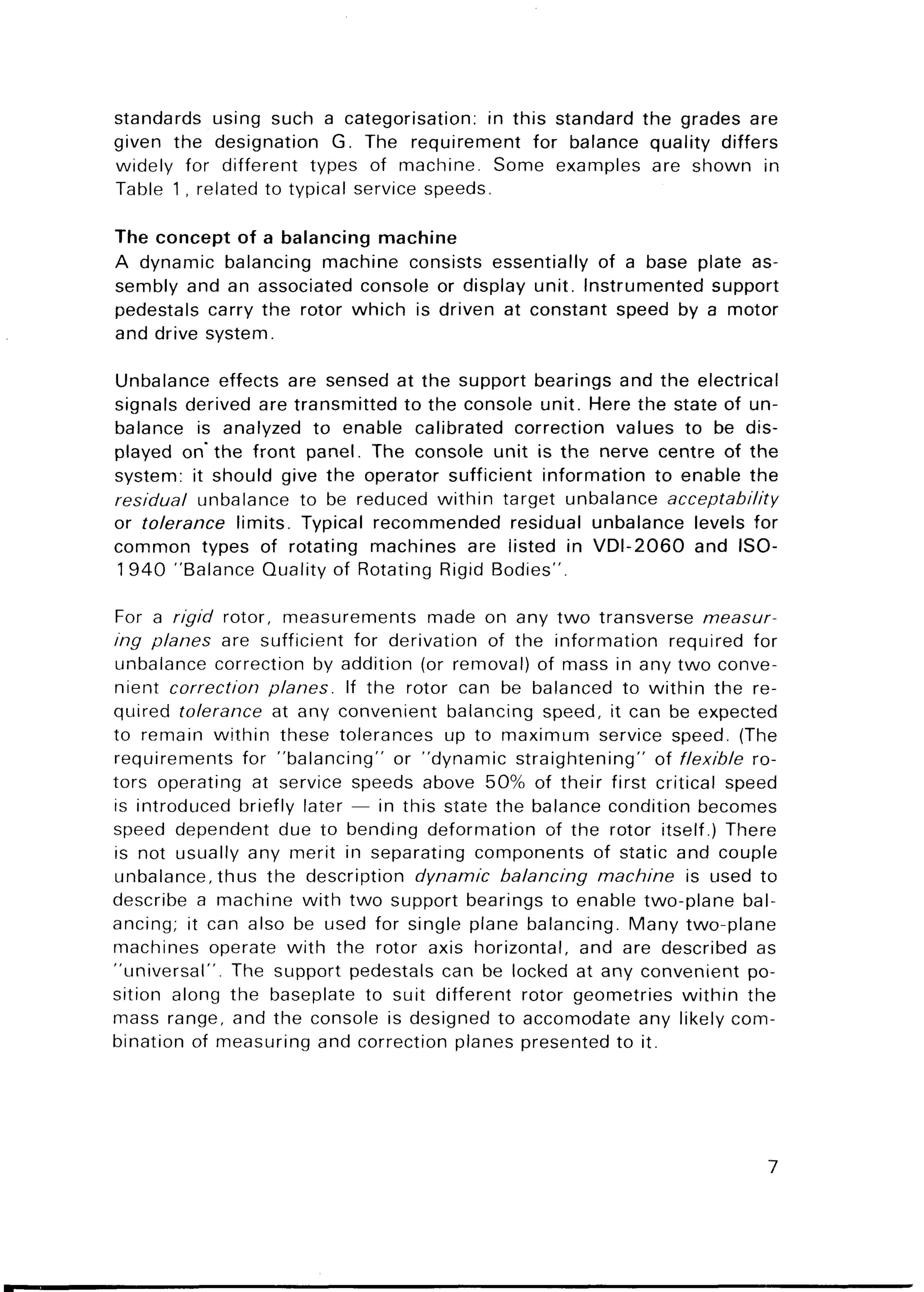
merits. In the past, resonance machines have offered the advantage that these displacements can be measured directly using mechanical measuring instruments. The considerable difficulty in ensuring stability and repeatability in this regime, together wi th the improved performance and stability of electronic instrumentat ion, has focused modern design on the more stable above- or below-resonance designs. Note that the descriptions of the various machine types refer to the dynamics of the suspension system supporting the work-piece and not to the type of journal bearings used. The different operating regimes are shown in Fig.2.
Fig. 2. Operating regions of balancing machines
1 1
The measuring system The type of transducer available, the type of rotor to be balanced, the work rate, and required residual unbalance are all factors which have influenced the development of modern soft- and hard-bearing machines.
The types of transducer used have been various. The first electronic machines of the 1930s used moving coil pick-ups, developed from loudspeakers, mounted on soft bearing support systems: these machines were themselves developments of existing balancing equipment. The large displacements could be measured relatively easily by connecting the pick-ups to modified wireless amplif iers. The development of the soft-bearing machine has been a logical one from the first patent registered by Henry Martinson in Canada in 1 8 7 0 .
There remained the problem of devising support systems which were sufficiently strong to support large rotors, yet sufficiently flexible to cope wi th the large amplitude excursions when balancing large rotors: these problems are particularly severe in cases of high initial unbalance and low rotation speed. Design focussed on hard-bearing construction, though the velocity pick-up remained widely used: a lever ratio was used to give mechanical amplif ication to the linear elastic motion of the journal bearing support members. To ensure that the motion of the rotor was restrained, and the unbalance force measured, a stronger, heavier machine evolved.
The high levels of precision required in industry, currently, taken wi th the increased availability of refined transducers and low-noise electronic circuitry, has fostered successive generations of balancing machine, of both types, which offer exceptional ruggedness and reliability in the industrial environment.
In the modern soft-bearing machine, the use of modern design techniques and lightweight materials enables the parasitic mass of the moving elements to be minimised for high sensitivity. Such a machine is shown in Fig.3. In this machine piezo-electric sensors measure absolute rather than relative motion, and are decoupled from external vibration effects through the support system. These elements have a wide dynamic range, have no moving parts, and are stable over a wide range of operating conditions. A secondary effect arising from the decoupling of the rotor system is that the baseplate and support posts can be of relatively l ightweight construct ion, resulting in a transportable machine offering high sensitivity over its mass range.
12

Fig. 3. Bruel & Kjaer direct drive soft-bearing production Balancing Machine Type 3905 — capacity 10 kg
For ease of construction, the support system allows for essentially unidirectional motion, usually in the horizontal, whi lst being relatively stiff in the orthogonal direction. Special conditions for fine balancing, of gyros for example, may require an isotropic suspension to be used; this type of rotor is balanced in its own bearings, and unnecessary loading of the bearings by the use of a hard support systems would affect the delicate balance of the rotor system.
Correspondingly, modern hard bearing machines use sensors which measure force at the bearing directly, or else the linear elastic motion of the support members. Piezo-electric elements or electrodynamic devices are commonly used to produce the output proportional to force. To restrain the rotor adequately a stronger, heavier form of construction is necessary for the baseplate and support members, thus offering the high mechanical impedance required at the bearings. To minimise the transmission of extraneous effects through the base bed to the sensors, a concrete foundation block is frequently included in the installation as a seismic mass.
Drive methods Belt drive is often used for small rotors, because individual drive connections are not required, rotors are changed quickly, and a high work rate achieved. The drive motor is typically mounted below the rotor wi th some form of overslung or tangential belt-drive arrangement to turn the rotor. Reference positions for the unbalance are obtained reSa-
13
tive to marks on the rotor itself, using a stroboscope and angle datum marks, or by using a tachometric pulse derived f rom a suitable probe unit. The penalty of using this system is that positive control of the rotor, and absolute f ixing of the unbalance angie, is forfeited; a quali f ied decision is required by the operator to determine the correct location for unbalance correct ion.
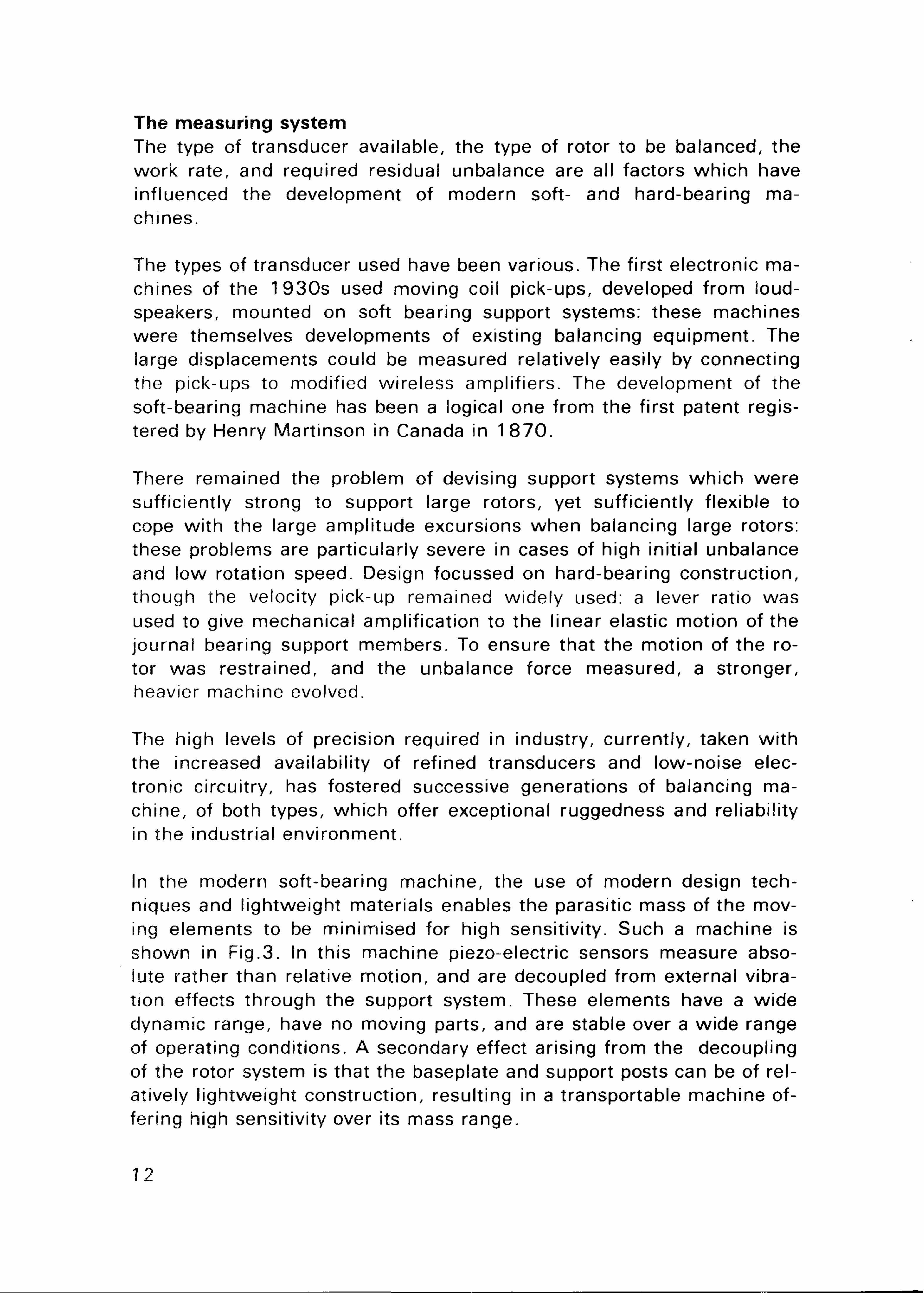
Direct drive through a connecting shaft and some form of universal coupl ing, w i th the component elements arranged axially, is also a common conf igurat ion. It is wel l -sui ted to the balancing of heavy rotors wh ich can then be run up to speed under the positive control of the motor to minimise overall measuring t ime. For all rotor types this system al lows direct recognition of the angle for unbalance correction and lends itself to automatic control w i th min imum supervision. In modern machines, careful attention to the design of the dr ive/coupl ing assembly ensures that machining tolerances and component misal ignment do not restrict the capability of the machine, whi ls t al lowing rapid change-over of rotors in a production series. Axial symmetry of screws and clamps on the coupling is important: by indexing the rotor by 9 0 ° or 1 8 0 ° , depending on the coupling design, it is possible to check that it is the rotor itself, and not the coupling elements whose unbalance has been compensated. These drive types are shown in Fig.4.
Fig.4. Drive configurations
For special applications, it is sometimes preferable to use other methods. Gyros which may require to be balanced successively at speeds up to their service speed — typically 2 0 0 0 0 — 2 4 0 0 0 rpm — to achieve the precision necessary (e. g. G 0 ,4 as recommended in ISO-1 940) , can be run up using their own drive. Electric or air-driven types are common. Similarly certain types of fans and turbocharger rotors are best
14

driven by air to simulate the service condition more closely. This criterion becomes increasingly important for balancing to fine quality grades better than G1 , due to the increasing significance of "quasi-unbalance" effects transmitted through the bearings which must also be reduced.
Instrumentation console Whichever type of transducer is used to measure unbalance, the task of analysis and display remains. The balancing machine console may be considered as a "dedicated" computer which processes the raw unbalance signals to yield calibrated correction values. The balancing bench and the console unit operate as complementary items of equipment; used correctly an unbalance reduction ratio of 80 — 90% should be achieved regularly in a single run.
In practice, the signals f rom the sensors do not have the simple s inusoidal form arising from cyclic effects of unbalance at the fundamental frequency, but also contain spurious signals from extraneous vibration, eccentricity of journals, air turbulence, etc. The measuring system must suppress higher order effects and noise to al low the unbalance to be analysed. Frequency discrimination is an important feature, and is effected using electronic fi lters or multiplier devices. The finer the balance quality required, the better the rejection characteristics of the f i l ter must be. The resulting unbalance signal is processed through a network of sensitivity- and mixing potentiometers so that appropriate calibrated correction values for the correction planes to be used, appear on the front panel. These corrections should be selectable by a switch as to mass addit ion, or mass removal, to suit individual applications.
In the production situation, simultaneous display of the unbalance corrections for the two planes is desirable; the use of a selector switch necessitates note taking as an intermediate step. The displays should also incorporate a memory facility so that they are maintained when the machine is stopped. Various forms of unbalance indicator are in use: these include all analogue displays, digi tal /analogue displays and all digital displays, as wel l as vector displays which give a direct polar representation of the unbalance. Analogue displays always involve some interpretation by the operator, and have meter movements which are relatively vulnerable and sensitive to environmental vibrat ion. Digital displays offer the potential for unambiguous interpretation of readings, periodic update of display to verify consistent operation, and high levels of repeatability and stability through the use of digital electronics.
15

In more specialized applications where components of unbalance have to be separated into vertical and horizontal components, or where a pictorial display is an advantage, the vectormeter display is useful; again the precision of the readings is limited by the divisions on the display graticule.
Calibration and operation Both soft- and hard-bearing machines must be calibrated to suit different rotor types. The procedure is one of plane separation or setting. The front panel controls are adjusted to enable the unbalance measurements made at each bearing to be related directly to a mass value required on an associated correction plane, without this mass affecting the display relating to the second correction plane. Basically, the controls are adjusted to mix the signal from one sensor, wi th part of the signal from the other, to derive a signal which is referred to its correction plane rather than to its measuring plane. In this way the operator can obtain independent readings for each correction plane, and the confusing correction plane interference or cross-effects, as shown in Fig.5, are minimised. The details of calibration differ for the two types, and reflect their fundamentally different operating principles.
Fig.5. Interaction between planes for unbalance on Plane A
In the soft-bearing machine, the measuring system senses motion at the bearing journal as developed in (11). The machine must be calibrated dynamically for each rotor type as the motion detected in the measuring plane is consequent upon the location of the centre of mass, the moment of inertia, and the mass of the rotor, as well as on its geometric configuration. The calibration procedure is carried out on a prototype rotor, usually the first in a production series; it consists of running
16

the rotor up to speed to investigate the effect of adding a trial mass to each of the two correction planes to be used, in tu rn , at the radius to be used for correction. Thus:
1 . The interaction between mass addition (or removal) on one correction plane and the display referred to the opposite correction plane can be minimised. Plane separation controls are used.
2. The displays for each correction plane can be adjusted to read directly in practical correction units, or convenient units for the production workshop. Typical units might be mass of a correction weight (g), length of a standard section of steel stock (mm), depth of a bore hole (mm), number of rivets, etc. These adjustments are made using calibration potentiometers.
Calibration is greatly accelerated when the console unit is equipped wi th compensators, as a balanced rotor is not required as the prototype. Compensator controls enable rotor balance to be simulated electronically before calibration: the compensators are switched out when calibrated measurements are to be made.
With the panel controls set, unbalance corrections can be found for any subsequent rotor in the series in a single balancing run. Where the calibration potentiometers are fitted wi th counters, the settings can be f i led, and recovered for future balancing on rotors of the same type.
Fig.6. Bruel & Kjaer Balancing Machine Console Type 2504 with two channel all digital display
17

In fact, the requirement for preliminary calibration runs is little penalty in series production situations. The runs are performed just once, and thereafter correction values are displayed in terms of any locally convenient units to be used in the production workshop. The calibration achieved is unique for a given rotor configuration, and has been made at the level of unbalance anticipated in production. Alternatively, the unbalance might be displayed in values of vibration velocity for direct comparison wi th unbalance quality grades recommended in ISO-1940 or VDI -2060 . A console wi th these features is il lustrated in Fig.6.
The same console unit, when connected to appropriate vibration transducers, is equally suitable for equipping in-house constructed balancing machines. The operating principle requires only that bearing response is linear over the range of unbalance experienced by the machine, and that the characteristics of the two supports is similar. Where these characteristics do not pertain, the effect of damping wi l l be to introduce a complex response coefficient between support bearings and correction planes such that the correction plane interference circuits can no longer adequately eliminate cross-effects.
For a hard-bearing machine, the measuring system senses force at the bearing journals as developed in (8). In this configuration the rotor system is statically determinate, and the usual rules of statics apply. By measuring the forces at the bearings, these can be referred to any other planes by geometric calculation. Thus the machine is permanently calibrated wi th in its capacity and speed range, but the panel controls must be pre-set according to the geometry of the rotor, and the relative location of measuring and correction planes. The dimensions to be set might include:
1 . Distance from left measuring plane to left correction plane. 2. Distance between measuring planes. 3. Distance between correction planes. 4 . Left and right plane correction radii.
The unbalance corrections are obtained on the first run; the accuracy achieved now depends on the accuracy w i th which the dimensions have been measured and the controls set. This procedure is particularly convenient in one-off balancing situations, or where balancing small numbers of large rotors at low speeds: the possibility of introducing unexpectedly high unbalance effects during a trial run is also el iminated. However, for series production there remain advantages in calibrating in a similar mode to the soft-bearing machine to ensure precision re-
18

suits in a particular plant installation. The hard bearing system is generally preferred for balancing of heavy rotors and in cases where the calibration by geometric setting gives a significant t ime saving. This is particularly useful when many different rotors are balanced as one-offs or in small numbers and handling time becomes an important proportion in overall balancing t ime. This system is also suitable in cases where aerodynamic effects are significant (e .g . certain types of large fan) and for balancing supercritical shafts where the bearings might provide a better simulation of operating conditions.
Additional factors The selection of balancing machine and display unit is clearly governed by many engineering factors relating to the intended application. Some of these are considered briefly here.
Where individual components are balanced on a mandrel (e .g . small fans and flywheels), prior to final assembly on a shaft, concentricity of diameters must be ensured, as wel l as adequate balance quality for the mandrel itself. Equally important is that a consistent approach is adopted to items such as locating keys and pegs: in US it is common to balance using a 1/2-key (flush wi th shaft) whi lst in Europe a full-key standard has been widely adopted. If possible all set screws should be arranged wi th axial symmetry such that the possibility of introducing mass eccentricity of the assembled element is minimised. The importance of evaluating the cumulative effects of the maximum eccentricity of machining tolerances on an assembly of individual components can be seen from Table 2. This shows typical and obtainable tolerances for radial cast obtained by various machining operations. It is advisable, where practical, to balance at successive stages of assembly to prevent a build up of unbalance.
— 1 Typical Obtainable
Turning 2 5 0 30 Boring 60 30 (fjm)
Precision Drill ing 40 20 Grinding 35 15
Table 2. Examples of typical and obtainable radial cast tolerances fpm) for various machining methods under ideal conditions
19
!
Typical Obtainable
Turning Boring Precision Drilling Grinding
250 60 40 35
30 3 0 (Aim) 20 15

Fans and compressor elements often suffer greatly from aerodynamic effects influencing the indicated correction values. For cylindrical fans it is sometimes convenient to use a paper shroud around the circumference, or to tape a paper disc over the exposed intake, to reduce these effects: turbine discs may be spun up in the contra service direction to ensure the blades adopt a similar position as when in service. On larger elements a vacuum chamber may be necessary to achieve good quality grades.
Certain rotating elements may be subject to plastic deformation in the early stages of service, until suitable work-hardening has occurred. To avoid the necessity to strip down and to rebalance a second t ime, it may be convenient to overspeed the rotor on the balancing machine so that the component is work-hardened and may be balanced before being put in service.
Wherever temperature, magnetic, or reciprocating phenomena affect the unbalance in the assembled machine, every attempt should be made to ensure that either the unbalance tolerances achieved on the balancing machine are adequate, or that these physical conditions can be duplicated in the balancing workshop. Experience shows that due to the complex behaviour of rotor-bearing systems, empirical work is usually necessary to ensure that the balance quality achieved on the balancing machine is maintained wi th the support conditions experienced in service.
The production engineer must also consider the human factors relating to the acceptability of a balancing machine. Amongst the features which might be considered important are:
1 . Ease of use after min imum instruction. 2. Clear, unambiguous display of unbalance. 3. Rapid interchangeability of rotors. 4 . Security system to minimise the danger to the operator during nor
mal operation and to prevent mechanical damage in cases of unsuspected high initial unbalance.
By consideration of these criteria it is most likely that the ful l advantages of improved balance quality of a product wi l l be obtained. Guidance as to a formal evaluation of balancing machines is outl ined in ISO-2953 "Balancing Machines — Description and Evaluation".
20

Portable instruments Many manufacturers offer field balancing equipment of the type illustrated in Fig.7. This equipment is particularly useful for in-situ balancing of assembled machines at the commissioning stage, or for use as a maintenance tool: it can also f ind application in the production shop.
Fig. 7. Bruel & Kjaer Type 9500. Typical battery operated portable vibration measuring set for field balancing
The method of measuring unbalance is very similar to that described for the soft-bearing machine in Section "Calibration and Operat ion", as for retro-fit of measurement sensors, vibration transducers are the logical choice. The technique was first described by Thearle and Schectaly in their paper "Dynamic Balancing of Rotating Machinery in the Field" in 1 956 . (APM-56-1 9). The dynamics of the rotor system and its associated parasitic masses must be evaluated by introducing known " t r i a l " unbalance in each correction plane, and observing the effects in the two measuring planes. This is necessary as the characteristics of the supports of an assembled machine are almost invariably unknown: in principle they could be anywhere between the " h a r d " and "sof t " regimes shown in Fig.2 as well as being different end for end. In fact, the unfortunate case of resonance on a lightly damped support may make balancing impractical until the service speed or support characteristics are changed.
Measurements of vibration amplitude, and phase relative to a geometric trigger reference point on the rotor (using a stroboscope or phase meter) for two measuring points, are taken. Two test or trial runs wi th a known unbalance placed in turn in each of the selected correction
21

planes enable the characteristics to be established. Analysis of the resulting twelve values (six vector quantit ies comprising both amplitude and phase) is very readily performed by the current generation of programmable pocket calculators on the market, such as HP-67 and TI59. Where full portability is not necessary, any available computing facility might be used to enable the two correction values to be calculated.
This equipment tends to require more know-how on the part of the user than the balancing machines mentioned earlier, but its key feature is its versatility. Not only is it, wi th a pocket calculator, fully portable, but transducer sensitivities and analysis program can be selected appropriate to the given measuring task. It is also used for analysis of other potential sources of vibrat ion, major culprits being misalignment at twice rotational speed, and loose elements or drive belts which may cause disturbance at various multiples of the fundamental .
Typical uses for this equipment are:
Extremely low production rate of large or specialized rotors which have to be run up in their own bearings and housings. "Cont ro l " of rotors where balancing is only necessary infrequently. Extremely large rotors, or where use of a conventional balancing machine would be impractical. Assembled machines whose mode of operation due to air-, hydraulic-or magnetic influences could not be simulated adequately on a balancing machine. Specialized investigations where these instruments, wi th their associated f i l ters, calculators etc., offer features not available on a conventional balancing machine console. Very wide range of maintenance balancing where corrosion, erosion, wear, and relative re-location of mating parts introduces unbalance in service.
Flexible rotors A rotor is said to be " f lex ib le" at operating speeds above 50% of its first natural bending mode. Whilst the balancing of a rigid rotor may be achieved by arbitrary selection of two axially separated correction planes, the unfortunate selection of these planes in the flexible condition can cause excitation of one or more natural bending modes. Stated simply, the rigid- or low-speed balancing operation does not al low for point by point axial correction of the unbalance. The forced vibrations associated wi th initial unbalance and lack of straightness are very important, and balancing machines are often used in this application.
22

For rotors w i th their mass concentrated at discrete axial positions (e .g . simple turbine assemblies), adequate balance quality can, in many cases, be achieved using low-speed techniques. In these cases the unbalance can be assumed to arise in these discrete axial locations, the discs, wh ich are the same as used for placing of corrections. Suitable design of correction planes, one at each end and one at the centre, is increasingly common for turbine and electric armature assemblies, as careful selection of planes may avoid the necessity for more complex, t ime-consuming high-speed balancing.
Distributed mass rotors, such as cardan shafts, have to be treated rather differently. For a generalized rotor, whose f lexural rigidity and mass per unit length are a funct ion of their axial posit ion, El (x) and m (x) respectively, the deformation y (x) at any rotation speed to may be wr i t ten:
[E l ( x )y " ] " - GJ2 m(x)y = F (12)
where F is the sum of forces due to unbalance, and the prime designat ion ' represents the differential operator d /dx . For unbalance having a "cont inuous" axial distr ibution u(x), mass eccentricity about the axis of rotat ion, its form may be expressed as:
u(x) = \ cn m (x) 0 n (x) n - 1,2,3 (1 3)
n
where cn is a constant and 0 n (x) is a solut ion, for the principal mode n, of differential equation (12) w i th F = 0 . By combinat ion of (1 2) and (13) and using the principle of orthogonali ty, principal modes can be predicted to occur at critical frequencies a>n, according to:
con = I m(x) 0 n2 (x) dx (1 4)
Knowledge about the principal modes of the rotor, either calculated or est imated, enables optima! correction planes to be selected. So called "h igh-speed" balancing techniques may then be used to perform the "dynamic s t ra ightening" operation. Each mode may be balanced close to its critical speed, cjn, balancing successive modes unti l the service speed lies at least 5 0 % below the subsequent crit ical speed. At each stage correction weights are applied in sets so that correction of one mode does not excite lower modes already balanced.
23

Fig. 8. Rotor Mode Shapes
24

The actual critical speeds wi l l depend on the support conditions. The first three principal modes for free-free, and rigid-rigid support systems are shown in Figs.8a and 8b respectively, whi lst the effects of using supports of interim stiffness is shown in Fig.8c. It wi l l be noted that since many soft-bearing balancing machines may be assumed rigid in the direction orthogonal to the "so f t " direction, two sets of critical frequencies arise: it is sometimes convenient to achieve the rigid-rigid modes and to use a displacement transducer to measure the amplitude excursion at the associated anti-node(s). In the case of both hard- and
Fig. 9. Exciting first three flexible modes of uniform rotor. (Sets chosen not to influence static or couple unbalance). Bending moment diagram and shape
25
soft- support systems the signal occurring at the measuring supports is not a simple function of unbalance force, but also of the flexural rigidity and mass distribution of the rotor: thus both types require a test run using a known trial mass set to enable subsequent estimation of the corrections. This correction may be shown quite simply for the first three, V-, S-, W-modes of a uniform cylindrical shaft in Figs.9 (a), (b), (c): it may be noted that these mass sets do not affect the static- or couple-unbalance condition of the shaft. For each subsequent bending mode one extra correction plane is required. This technique, described as modal balancing, may not necessarily require rigid-rotor balancing at all: however, where the flexibil ity in service arises from characteristics of the foundation rigid-rotor balancing fol lowed by high-speed balancing, or vice,versa, may be preferable. [Refs. 1 , 2].
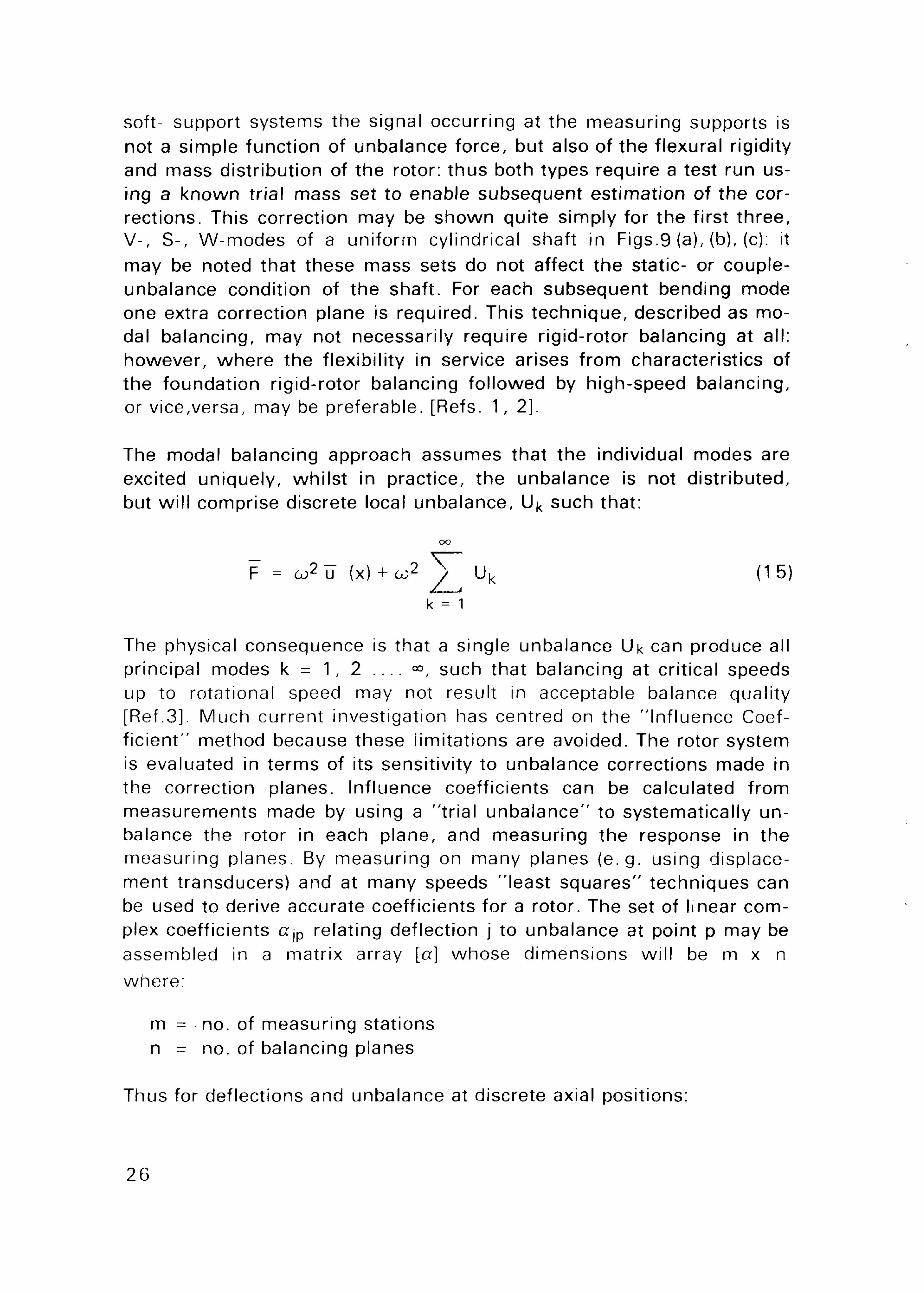
The modal balancing approach assumes that the individual modes are excited uniquely, whi lst in practice, the unbalance is not distr ibuted, but wi l l comprise discrete local unbalance, U^ such that:
oo
F = a;2 u (x) + co2 V " Uk (15)
k = 1
The physical consequence is that a single unbalance Uk can produce all principal modes k = 1 , 2 », such that balancing at critical speeds up to rotational speed may not result in acceptable balance quality [Ref.3]. Much current investigation has centred on the "Influence Coeff ic ient" method because these limitations are avoided. The rotor system is evaluated in terms of its sensitivity to unbalance corrections made in the correction planes. Influence coefficients can be calculated from measurements made by using a "tr ial unbalance" to systematically unbalance the rotor in each plane, and measuring the response in the measuring planes. By measuring on many planes (e .g . using displacement transducers) and at many speeds "least squares" techniques can be used to derive accurate coefficients for a rotor. The set of linear complex coefficients aiP relating deflection j to unbalance at point p may be assembled in a matrix array [a] whose dimensions wi l l be m x n
where:
m = no. of measuring stations n = no. of balancing planes
Thus for deflections and unbalance at discrete axial positions:
26
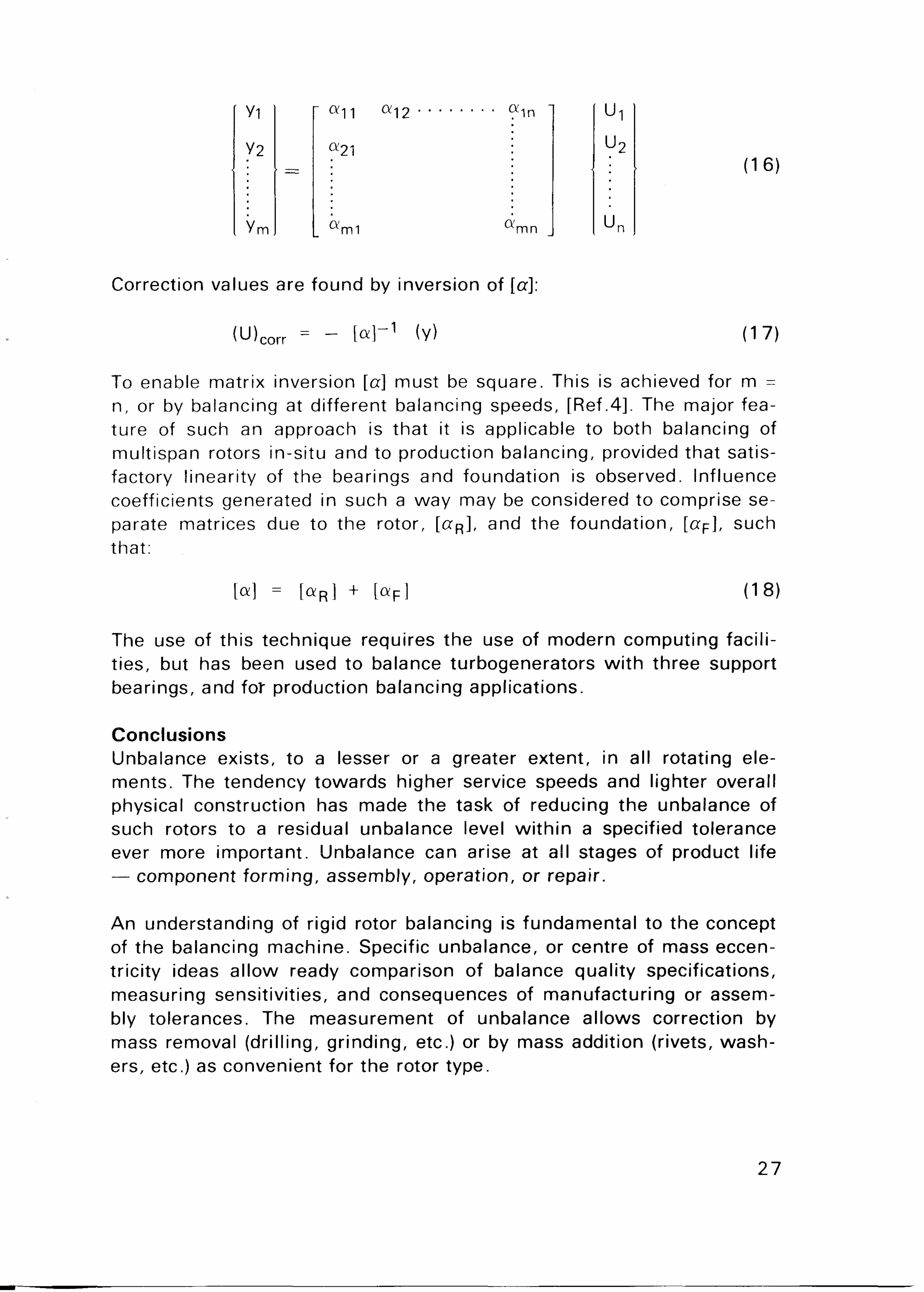
Correction values are found by inversion of [a]:
(U)corr = ~ N ~ 1 (V) (17)
To enable matrix inversion [a] must be square. This is achieved for m = n, or by balancing at different balancing speeds, [Ref.4]. The major feature of such an approach is that it is applicable to both balancing of multispan rotors in-situ and to production balancing, provided that satisfactory linearity of the bearings and foundation is observed. Influence coefficients generated in such a way may be considered to comprise separate matrices due to the rotor, [ a R ] , and the foundation, [a F ] , such that:
[a] = [<*R] + [ « F ! <18>
The use of this technique requires the use of modern computing facil it ies, but has been used to balance turbogenerators wi th three support bearings, and for production balancing applications.
Conclusions Unbalance exists, to a lesser or a greater extent, in all rotating elements. The tendency towards higher service speeds and lighter overall physical construction has made the task of reducing the unbalance of such rotors to a residual unbalance level wi th in a specified tolerance ever more important. Unbalance can arise at ail stages of product life — component forming, assembly, operation, or repair.
An understanding of rigid rotor balancing is fundamental to the concept of the balancing machine. Specific unbalance, or centre of mass eccentricity ideas al low ready comparison of balance quality specifications, measuring sensitivit ies, and consequences of manufacturing or assembly tolerances. The measurement of unbalance allows correction by mass removal (dril l ing, grinding, etc.) or by mass addition (rivets, washers, etc.) as convenient for the rotor type.
27
(16)
The trend in high-volume balancing is fol lowing the pattern of current machine tool technology, wi th increasing use of fully automated balancing systems dedicated to a specific task. In contrast, the series- or one-off balancing installation has prime requirements for versatil ity and ease of use: work-rate in itself is not the overriding factor.
In recent years it has been found necessary to consider the interaction between the rotor and its bearings and foundation used in service. Where balancing on a balancing machine does not provide adequate unbalance quality fol lowing final assembly, portable balancing equipment is often used for the " t r im"-balancing task. As an extension of this work computer techniques are currently under investigation for balancing of flexible rotors, and for flexible rotors w i th multiple support systems.
References [1] BISHOP R. E. D. & "On the Use of Balancing Machines for
PARKINSON A. G. Flexible Rotors". ASME 71-Vibr . -73.
[2] KELLENBERGER W. "Should a Flexible Rotor be Balanced in N or (N + 2) planes. ASME 71-Vibr . -55.
[3] MOORE L. S. & "Mass Balancing of Large Flexible Ro-D O D D E . G . tors" . GEC Journal Vol. 3 1 , No. 2.
1964 .
[4]TESSERZIK J . M. "Flexible Rotor Balancing by the Exact BADGLEY R. H. & Point-Speed Influence Coefficient ANDERSON W. J . Method" . ASME 71 -Vibr.-91 .
r
-
-.■ - ■■
- - " ■ ^
28

News from the Factory
Building Acoustics Analyzer Type 4 4 1 7
The Building Acoustics Analyzer Type 4 4 1 7 is designed for the automatic measurement and subsequent calculation of the common quantities of interest in the sphere of building acoustics, and for precision sound power measurements. These quantities (e .g . reverberation t ime, impact and airborne insulation, sound power, normalised and standardised levels) are determined in 20 third octave bands covering the frequency range 1 00 Hz to 8 kHz (centre frequency). The results can be presented digitally on the Type 441 7's display, graphically via a level recorder, printed via an alphanumeric printer or stored on a digital cassette recorder.
The Type 4 4 1 7 is a portable (weight 7 kg), battery-powered instrument suitable both for on site measurements and for permanent laboratory arrangements. All the controls of the Type 4 4 1 7 , access to the battery box and all inputs and outputs (except the digital output) are on the front panel. This makes the Type 4 4 1 7 eminently suitable for portable use and for installing in the practical Carrying Case KA 2 0 0 0 . The Type 4 4 1 7 contains a random noise generator and is capable of producing third octave band limited random noise so that in conjunction wi th a microphone and a loudspeaker system (or other sound source or even a vibration exciter) the Type 4 4 1 7 constitutes a complete measurement and computational system. List of the measurement and calculation capabilities of the Type 4 4 1 7 is given in the Table. When both the two inputs (channel A and Channel B) and the two outputs (Channel A and Channel B) of the Type 441 7 are employed, a completely automatic system for measuring insulation and reverberation times is obtained. The
29

Type 4417 wil l retain in its memory measurement data for 3 level-spectra and 1 reverberation-time spectrum. From these data and the entered values of the room's volume and the room's (or wall's) surface area, the Type 4417 wil l calculate any or all of 9 important spectra (see Table).
Calculation Equation
Background Noise Level Correction L2 <a n d calculations using L2)
corrected for Background Noise Level L2B
Level Difference D = L1 " L 2
D n T = D + 1 0 l o g i n ( — ) (ISO 140) -Standardised n l 1 U ' 0 , 5 ^
/6,15 S T \ -Normalised R = D + 1 0 l o g 1 0 ( — — j (ISO 140)
— Index la = Insulation Index (ISO R 717)
Impact Level L, = L2
-Standardised Ln T - L , - 1 0 l o g 1 0 ( ) (ISO 140)
/ 61,5 T \ -Normalised Ln - Lj - 10 log1 0 ^ — — J (ISO 140)
— Index lj = Impact Index (ISO R 717)
/ V + 4^A-\ / ISO 3741 v Sound Power Lw = L2 + 10 log, n ( — 1 _ ) - 14 & 3742
V T / \ Method 1/
790793
Miniature Accelerometers Types 4 3 7 4 and 4 3 7 5
These accelerometers are well suited for measurements on lightweight structures where relatively high level, high frequency vibrations are commonly encountered, and where the use of heavier transducers would alter the mode of vibration, invalidating measurements. Typical application areas are measurements on thin vibrating panels including
30
Calculation Equation
Background Noise Level Correction \_2 (and calculations using L2)
corrected for Background Noise Level L2B
Level Difference D = !_! - L2
—Standardised D n T = D + 1 0 l o g 1 0 ( ^ - ) (ISO 140)
—Normalised /6,15 S T \
R - D + 10 log1 0 ( v j (ISO 140)
—Index L = Insulation Index d
(ISO R 717)
Impact Level Li = L2
—Standardised Ln T = L i - 1 0 l o g 1 0 ( o 5 ) (ISO 140)
—Normalised / 61,5 T \
Ln = L; - 1 0 l o g 1 0 ( v ) (ISO 140)
—Index lj = Impact Index (ISO R 717)
( y +4 3
fs ^ / ISO 3741 v
Sound Power I = L i + 1 n loa in l ) - 1 4 & 3 7 4 2 \ Method 1/
Sound Power L w *-/ ' w i wy 10 \ T ) ) - 1 4 & 3 7 4 2
\ Method 1/
790793

aircraft and automobile bodies, model testing, work in confined spaces and measurement of moderately high level shock.
Type 4374 is of planar shear construction, weighs approximately 0,65 grams and is suitable for measurement at frequencies up to 27 kHz, whilst Type 4375 is of delta shear construction, weighs approximately 2 grams and can be used for measurements of frequencies up to 18 kHz. Both accelerometers have an integral 40 cm long connection cable with miniature coaxial plug attached — Type 4374 having a plane base for wax or cement mounting and Type 4375 having an M3 screw thread for stud mounting.
31

PREVIOUSLY ISSUED NUMBERS OF BRUEL & KJ/ER TECHNICAL REVIEW
(Continued from cover page 2)
2-1 975 On the Averaging Time of RMS Measurements. Averaging Time of Level Recorder Type 2 3 0 6 and "Fast" and "S low" Response of Level Recorders 2 3 0 5 / 0 6 / 0 7 .
1 -1 975 Problems in Telephone Measurements. Proposals for the Measurement of Loudness Ratings of Operator's Headsets. Comparison of Results obtained by Subjective Measuring Methods. Repeatabilities in Electro-Acoustic Measurements on Telephone Capsules. Stable Subset Measurements w i th the 73D. Vibration Testing of Telephone Equipment.
4-1 9 7 4 Underwater Impulse-Measurements. A Comparison of ISO and OSHA Noise Dose Measurements. Sound Radiation from Loudspeaker System wi th the Symmetry of the Platonic Solids.
3-1 9 7 4 Acoustic Investigation of an Impact Dri l l . Measurement of the Dynamic Mass of the Hand-arm System.
2-1 9 7 4 On Signal/Noise Ratio of Tape Recorders. On the Operating Performance of the Tape Recorder Type 7 0 0 3 in a Vibrating Environment.
SPECIAL TECHNICAL LITERATURE
|As shown on the back cover page, Bruel & Kjaer publish a variety of "Technical literature which can be obtained from your local B & K repre
sentative. The fol lowing literature is presently available:
Mechanical Vibration and Shock Measurements (English, German, Russian) Acoustic Noise Measurements (English), 3 edition Acoustic Noise Measurements (Russian), 2 edition Architectural Acoustics (English) Strain Measurements (English, German, Russian) Frequency Analysis (English) Electroacoustic Measurements (English, German, French, Spanish) Catalogs (several languages) Product Data Sheets (English, German, French, Russian)
Furthermore, back copies of the Technical Review can be supplied as shown in the list above. Older issues may be obtained provided they are still in stock.
Printed in Denmark by Naerum Offset
