technicearch -...
TRANSCRIPT

TABLE OF CONTENTS
1
2
2.1
2.2
3 Description of activities and discussion ....................................................................................... 11
3.1 Experimental work................................................................................................................ 11
3.1.1 Tests performed by VTT ..................................................................................................... 11
3.1.2 Tests performed by CTICM ................................................................................................ 14
3.1.3 Tests performed by TNO..................................................................................................... 16
3.2 Development of a model intended to predict transient thermal actions to external
structure ............................................................................................................................................. 17
3.2.1 Validation of numerical tools .............................................................................................. 18
3.2.2 Study of main parameters affecting external flames characteristics ................................... 19
3.2.2.1 Effect of opening ......................................................................................................... 19
3.2.2.2 Effect of fuel................................................................................................................ 19
3.2.2.3 Effect of compartment characteristics ......................................................................... 21
3.2.2.4 Effect of external obstructions..................................................................................... 22
3.2.2.5 Effect of wind .............................................................................................................. 22
3.2.3 Development of a simple model for predicting thermal actions to external structure......... 23
3.2.3.1 Simplifying assumptions ............................................................................................. 23
3.2.3.2 Strategy........................................................................................................................ 23
3.2.3.3 Sub models description................................................................................................ 24
3.2.3.4 Global model validation .............................................................................................. 24
3.3 Steel structures exposed to unconfined localized fire......................................................... 25
3.4 Thermal response of bare and composite steel structures ................................................. 26
3.4.1 Model description................................................................................................................ 26
3.4.2 Model validation.................................................................................................................. 27
3.4.3 Conclusion........................................................................................................................... 28
3.5 Thermal response of protected steel structures .................................................................. 28
3.5.1 Introduction ......................................................................................................................... 28
3.5.2 Use of intumescent coating ................................................................................................. 28
3.5.3 Determination of equivalent thermal properties .................................................................. 28
3.5.4 Validation ............................................................................................................................ 29
3.5.5 Conclusion........................................................................................................................... 30
3.6 Thermal response of encased structures and balconies ..................................................... 30
3.6.1 Experimental tests description............................................................................................. 30
3.6.1.1 Encased elements......................................................................................................... 30
3.6.1.2 Previous tests concerning balconies ............................................................................ 30
3.6.1.3 Previous tests concerning steel emissivity................................................................... 30
3.6.2 Numerical simulations description ...................................................................................... 30
3.6.3 Model development description .......................................................................................... 31
3.6.3.1 Encased elements......................................................................................................... 31
3.6.3.2 Balconies ..................................................................................................................... 31
3.7 Methodology for evaluating the heating of external structures ........................................ 31
3.7.1 Transient method for thermal actions.................................................................................. 32
3.7.1.1 Level 1: simple geometry and openings a the same height ......................................... 33
3.7.1.2 Level 2: multiple opening with different heights ........................................................ 34
3.7.1.3 Level 3: complex geometry and specific fluid flows................................................... 34
3.7.2 Thermal response and mechanical behaviour...................................................................... 35
3
Objectives of the project ................................................................................................................. 5
Comparison of initially planned activities and work accomplished ........................................... 7
Management of the project..................................................................................................... 7
Communication ....................................................................................................................... 9

3.8 Example of application of the methods developed during this project............................. 35
3.8.1 Introduction ......................................................................................................................... 35
3.8.1.1 Building configuration................................................................................................. 35
3.8.1.2 External members configuration ................................................................................. 36
3.8.1.3 Mechanical loads ......................................................................................................... 36
3.8.1.4 Critical temperature of the columns ............................................................................ 36
3.8.1.5 External members temperatures .................................................................................. 37
3.8.1.6 Fire stability of unprotected columns .......................................................................... 37
3.8.2 Application of the PR380 methods to protect columns ....................................................... 38
3.8.2.1 Estimation of the design HRR curve ........................................................................... 38
3.8.2.2 Concrete filled section................................................................................................. 39
3.8.2.3 Protected steel section ................................................................................................. 42
3.8.2.4 Encased section ........................................................................................................... 46
4
5
6
6.1
6.2
7
8
4
Conclusions .................................................................................................................................... 53
Exploitation and impact of the research results ......................................................................... 55
List of figures and tables............................................................................................................... 57
Figures .................................................................................................................................... 57
Tables...................................................................................................................................... 58
List of references ........................................................................................................................... 59
Technical Annex ............................................................................................................................ 65

1 OBJECTIVES OF THE PROJECT
The objectives of the present research are recalled below. This work in intended:
‚ To improve the existing model for determining the thermal actions on external bare, insulated
or shielded structural elements, taking into account radiative and convective heating by external
flames and by the opening of the compartment in fire itself
‚ To extend the existing physical model for temperature development within structural elements
(steel or composite) by including transient state conditions and, when necessary, the effects of
fire protection systems such as fire insulation and thermal shielding, taking into account heat
transfer across air gaps
‚ To verify the developed models on the basis of experimental results and to adapt the models,
where appropriate
‚ To develop simple rules on the heating of bare or protected external steel sections, steel section
away from a localized fire and balconies, in case of fire
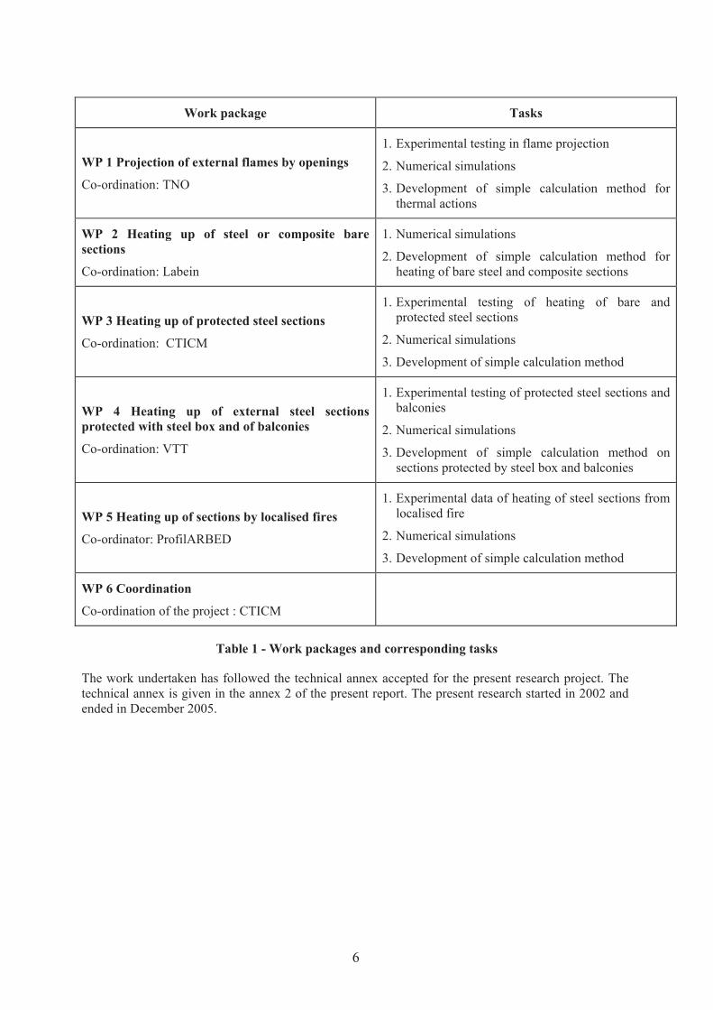
The effort has been divided in 6 work packages. A single work package is about the coordination of the
activities. The first work package is devoted to the estimation of thermal actions to structural elements.
The others deal with the temperature response of specific types of structural elements or specific fire
protection conditions. Within each work package, three types of work are considered. These types are:
‚ adjustment and development of models, on the basis of literature and numerical tools results
‚ experimental verification of models predictions
‚ development of simple rules to estimate the heating of external members during a fire
The title and the tasks associated with each work package are summarized in the table below.
5
Work package Tasks
WP 1 Projection of external flames by openings
Co-ordination: TNO
1. Experimental testing in flame projection
2. Numerical simulations
3. Development of simple calculation method for
thermal actions
WP 2 Heating up of steel or composite bare
sections
Co-ordination: Labein
1. Numerical simulations
2. Development of simple calculation method for
heating of bare steel and composite sections
WP 3 Heating up of protected steel sections
Co-ordination: CTICM
1. Experimental testing of heating of bare and
protected steel sections
2. Numerical simulations
3. Development of simple calculation method
WP 4 Heating up of external steel sections
protected with steel box and of balconies
Co-ordination: VTT
1. Experimental testing of protected steel sections and
balconies
2. Numerical simulations
3. Development of simple calculation method on
sections protected by steel box and balconies
WP 5 Heating up of sections by localised fires
Co-ordinator: ProfilARBED
1. Experimental data of heating of steel sections from
localised fire
2. Numerical simulations
3. Development of simple calculation method
WP 6 Coordination
Co-ordination of the project : CTICM
Table 1 - Work packages and corresponding tasks
The work undertaken has followed the technical annex accepted for the present research project. The
technical annex is given in the annex 2 of the present report. The present research started in 2002 and
ended in December 2005.
6

2 COMPARISON OF INITIALLY PLANNED ACTIVITIES AND
WORK ACCOMPLISHED
2.1 Management of the project
Responsible partner: CTICM
Objectives: Overall management of the project.
The project has been coordinated by CTICM. This coordination has consisted in holding meetings
during the research, and ensuring that the work schedule was respected as far as possible1. For every
meeting, minutes have been written in order to give a summary of actions to be performed by each
partner. The coordinator was also in charge of the semestrial, annual and final reports, and presentations
to the TGS8 committee.
During this research, communication has been established with Margaret Law. She has given her
opinion about the weakness of her model and about recent literature on external flames.
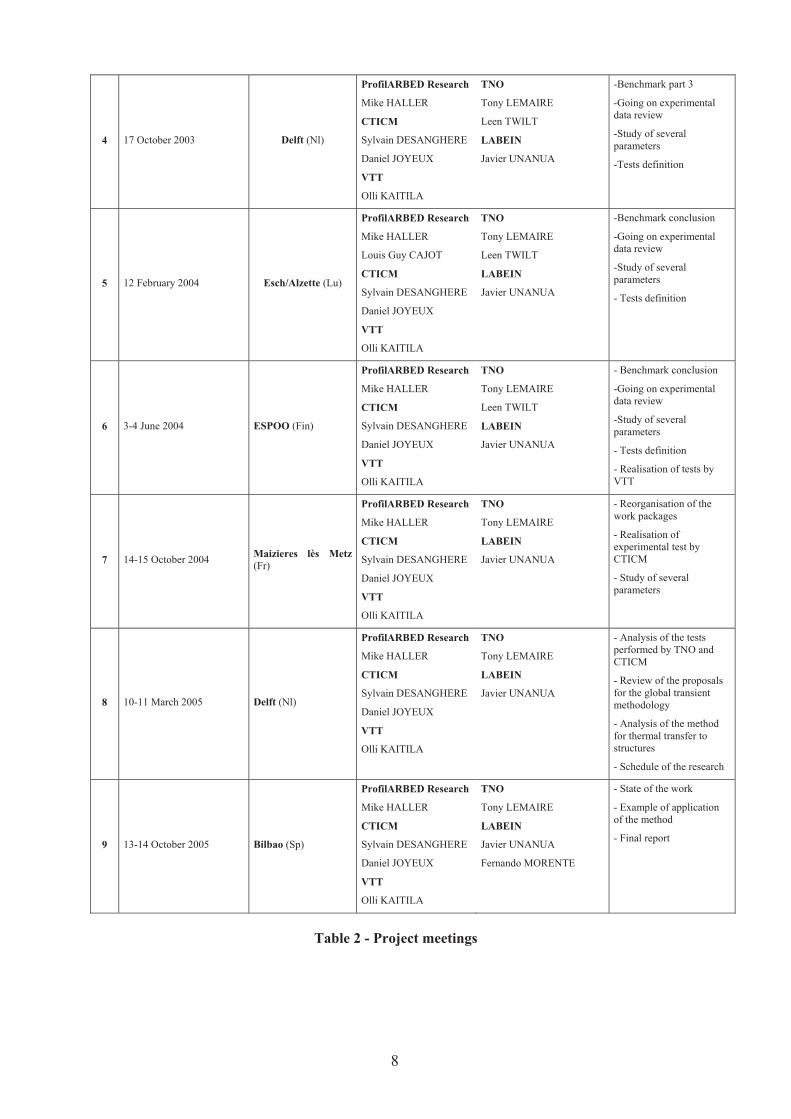
The meetings held since the beginning of the research are summarized in the table below.
N° DATE PLACE ATTENDANT ACTIONS
1 20 September 2002 Paris (Fr)
ProfilARBED Research
Olivier VASSARD
Louis Guy CAJOT
CTICM
Daniel JOYEUX
Joel KRUPPA
VTT
Jukka MYLLYMAK
TNO
Tony LEMAIRE
Leen TWILT
LABEIN
Jesus De La QUINTANA
Javier UNANUA
-Presentation of the project
-Literature review
2 16 January 2003 Paris (Fr)
ProfilARBED Research
Mike HALLER
Louis Guy CAJOT
CTICM
Sylvain DESANGHERE
Daniel JOYEUX
Joel KRUPPA
VTT
Jukka MYLLYMAK
TNO
Tony LEMAIRE
LABEIN
Jesus De La QUINTANA
Javier UNANUA
-Benchmark definition
-Review on experimental
data
-Literature review
3 28 June 2003 Bilbao (Sp)
ProfilARBED Research
Mike HALLER
CTICM
Sylvain DESANGHERE
Daniel JOYEUX
VTT
Olli KAITILA
TNO
Tony LEMAIRE
Leen TWILT
LABEIN
Jose Miguel FERNANDEZ
Javier UNANUA
-Benchmark part 2
-Going on experimental
data review
-Study of several
parameters
1 An extension of 6 months has been requested due to delay about experimental works and was accepted
by European Commission.
7
4 17 October 2003 Delft (Nl)
ProfilARBED Research
Mike HALLER
CTICM
Sylvain DESANGHERE
Daniel JOYEUX
VTT
Olli KAITILA
TNO
Tony LEMAIRE
Leen TWILT
LABEIN
Javier UNANUA
-Benchmark part 3
-Going on experimental
data review
-Study of several
parameters
-Tests definition
5 12 February 2004 Esch/Alzette (Lu)
ProfilARBED Research
Mike HALLER
Louis Guy CAJOT
CTICM
Sylvain DESANGHERE
Daniel JOYEUX
VTT
Olli KAITILA
TNO
Tony LEMAIRE
Leen TWILT
LABEIN
Javier UNANUA
-Benchmark conclusion
-Going on experimental
data review
-Study of several
parameters
- Tests definition
6 3-4 June 2004 ESPOO (Fin)
ProfilARBED Research
Mike HALLER
CTICM
Sylvain DESANGHERE
Daniel JOYEUX
VTT
Olli KAITILA
TNO
Tony LEMAIRE
Leen TWILT
LABEIN
Javier UNANUA
- Benchmark conclusion
-Going on experimental
data review
-Study of several
parameters
- Tests definition
- Realisation of tests by
VTT
7 14-15 October 2004 Maizieres lès Metz
(Fr)
ProfilARBED Research
Mike HALLER
CTICM
Sylvain DESANGHERE
Daniel JOYEUX
VTT
Olli KAITILA
TNO
Tony LEMAIRE
LABEIN
Javier UNANUA
- Reorganisation of the
work packages
- Realisation of
experimental test by
CTICM
- Study of several
parameters
8 10-11 March 2005 Delft (Nl)
ProfilARBED Research
Mike HALLER
CTICM
Sylvain DESANGHERE
Daniel JOYEUX
VTT
Olli KAITILA
TNO
Tony LEMAIRE
LABEIN
Javier UNANUA
- Analysis of the tests
performed by TNO and
CTICM
- Review of the proposals
for the global transient
methodology
- Analysis of the method
for thermal transfer to
structures
- Schedule of the research
9 13-14 October 2005 Bilbao (Sp)
ProfilARBED Research
Mike HALLER
CTICM
Sylvain DESANGHERE
Daniel JOYEUX
VTT
Olli KAITILA
TNO
Tony LEMAIRE
LABEIN
Javier UNANUA
Fernando MORENTE
- State of the work
- Example of application
of the method
- Final report
Table 2 - Project meetings
8
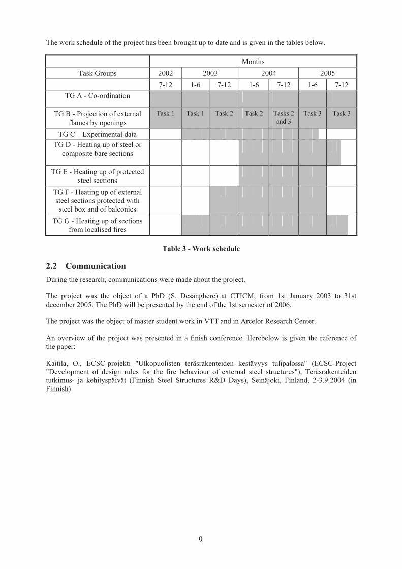
The work schedule of the project has been brought up to date and is given in the tables below.
Months
Task Groups 2002 2003 2004 2005
7-12 1-6 7-12 1-6 7-12 1-6 7-12
TG A - Co-ordination
TG B - Projection of external
flames by openings
Task 1 Task 1 Task 2 Task 2 Tasks 2
and 3
Task 3 Task 3
TG C – Experimental data
TG D - Heating up of steel or
composite bare sections
TG E - Heating up of protected
steel sections
TG F - Heating up of external
steel sections protected with
steel box and of balconies
TG G - Heating up of sections
from localised fires
Table 3 - Work schedule
2.2 Communication
During the research, communications were made about the project.
The project was the object of a PhD (S. Desanghere) at CTICM, from 1st January 2003 to 31st
december 2005. The PhD will be presented by the end of the 1st semester of 2006.
The project was the object of master student work in VTT and in Arcelor Research Center.
An overview of the project was presented in a finish conference. Herebelow is given the reference of
the paper:
Kaitila, O., ECSC-projekti "Ulkopuolisten teräsrakenteiden kestävyys tulipalossa" (ECSC-Project
"Development of design rules for the fire behaviour of external steel structures"), Teräsrakenteiden
tutkimus- ja kehityspäivät (Finnish Steel Structures R&D Days), Seinäjoki, Finland, 2-3.9.2004 (in
Finnish)
9

3 DESCRIPTION OF ACTIVITIES AND DISCUSSION
3.1 Experimental work
Within the project, a review of many tests performed from 1970 to now has been done.
The analysis was mainly focussed on tests integrating added value for the present project:
‚ balconies tests from VTT used within the TG F about the improvement of the Eurocode 1
model concerning the effect of balconies on flame deviation (ref n°15, VTT)
‚ external flaming tests performed with protected steel elements (more recent tests performed at
CTICM), (ref n°59 to n°67 – CTICM)
‚ external flaming tests performed with hollow core steel sections filled of concrete (recent tests
performed, ref n°71- CTICM)
‚ External flaming with wall properties effect (ref n°5 and 6, CTICM tests)
‚ External flaming with lateral wind effect (German study)
Nevertheless, additional tests were necessary for validation of the global methodology. So,
experimental work has been performed as presented in the technical annex. Several tests have been
realized by VTT, CTICM and TNO.
The objectives of the tests were:
‚ validation of parameters effects of the eurocode model relevant to the WP1
‚ validation of the heating response model for composite structures (WP2)
‚ validation of the heating response model for protected steel sections by intumescent coating
(WP3)
‚ validation of the heating response model for encased structures (WP4)
All the results are provided in a CDROM joined to the final reports, in terms of analysis of the results,
reports and excel results. The results are also used for each WP work, presented as comparison in their
appendix reports. The following chapters are just short presentations of the tests performed by the three
partners.
It can be noticed that Arcelor gave freely the steel sections used during the different tests.
3.1.1 Tests performed by VTT
Four structural fire tests have been carried out in 2004 as part of the ECSC research project PR380
"Development of design rules for the fire behaviour of external steel structures". The test data is used in
the development of numerical calculation methods for the evaluation of the fire resistance of external
steel structures.
The fire tests were carried out using the VTT Building and Transport facade apparatus. The columns
were placed in front of the 3000 mm · 1200 mm large fire room window in order to study the heating
up of external steel columns with different types of fire protection. A total of 12 columns were tested -
three columns in each of the four tests. In each test, two columns were placed symmetrically in front of
the fire room window and one column was placed at the level of the side of the window.
11
The results can be used to provide basic data on the influence of a selection of different fire protection
methods on the temperatures of the columns and to study the differences in the temperature
development between structural steel columns and stainless steel columns.
The fire load consisted of wood cribs (made with 38 mm · 40 mm · 800 mm wood battens) and
particle boards with total weights of approximately 375 kg and 260 kg, respectively, corresponding to
an approximate fire load density of 180 MJ/m2 calculated for the total room area and 986 MJ/m2
calculated for the floor area, when the heat of combustion of wood is 14 MJ/kg. The fire load was
designed so as to have flames coming out of the fire room window for about 30 minutes.
Six column types with different fire protection materials were tested as summarized in Table 4. These
column types were also tested in fire resistance testing conditions according to standard ISO fire for
comparison in the Horizontal Furnace. All columns were of 4500 mm length. The stainless steel grade
was AISI 304 (EN 1.4301) and the structural steel grade for columns was S355 (EN 10025) and DX51
(EN 10142) for PVDF-coated casings.
Column
type tag
Number of
tested
specimens
Column
profile
Column material F/V
[1/m]
Fire protection
M-RHS-Paint 1 RHS 150x150x5 S355 Structural steel 206 Intumescent paint
S-RHS-Sbox 3 RHS 150x150x5 AISI 304 Stainless steel 206 Stainless steel casing
M-RHS-Sbox 3 RHS 150x150x5 S355 Structural steel 206 Stainless steel casing
S-RHS-Unp 1 RHS 150x150x5 AISI 304 Stainless steel 206 None
M-RHS-MBox 2 RHS 150x150x5 S355 Structural steel 206 PVDF-coated structural steel
casing
M-HEA-Mbox 2 HEA 200 S355 Structural steel 212 PVDF-coated structural steel
casing
Table 4 - Description of test specimen types
One structural steel RHS column was protected with intumescent paint UNITHERM 38091 External,
one stainless steel RHS column was left bare and the remaining columns were protected with a thin
steel sheet casing made of either stainless steel or structural steel with PVDF-coating. An air gap of
approximately 12 mm was left between the column and the casing. The ends of the columns were
closed using welded steel plates and stone wool insulation in order to prevent the flow of hot gases
through the ends.
To get a general overview of the results, the maximum temperatures reached for each column specimen
during the tests are collected in Table 5.
12

Test # -
Column # Specimen type
Maximum
temperature
reached during
the test
Time from ignition to
reaching maximum
temperature
Thermocouple
number
Thermocouple
location
T1-C1 M-RHS-Sbox 989°C 26 min 1031 h = 3560 mm,
toward window
T1-C2 S-RHS-Sbox 911°C 27 min 1076 h = 3560 mm,
toward window
T1-C3 M-RHS-Mbox 548°C 33 min 1091 h = 1960 mm,
toward window
T2-C1 S-RHS-Unp 971°C 14 min 30 s 2016 h = 2760 mm,
toward window
T2-C2 M-RHS-Sbox 789°C 22 min 2061 h = 2760 mm,
toward window
T2-C3 S-RHS-Sbox 484°C 35 min 2091 h = 1960 mm,
toward window
T3-C1 S-RHS-Sbox 866°C 20 min 3016 h = 2760 mm,
toward window
T3-C2 M-HEA-Mbox 808°C 31 min 3077 h = 3560 mm,
toward window
T3-C3 M-RHS-Sbox 493°C 35 min 40 s 3091 h = 1960 mm,
toward window
T4-C1 M-RHS-Mbox 821°C 34 min 4001 h = 1960 mm,
toward window
T4-C2 M-RHS-Paint 479°C 32 min 4079 h = 3560 mm,
right side
T4-C3 M-HEA-Mbox 549°C 35 min 4092 h = 1960 mm,
toward window
Table 5 - Maximum temperatures reached for each specimen during the tests
Figure 1 - Overview of VTT test 1
13
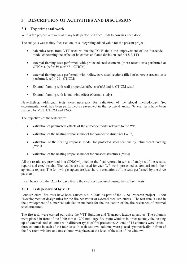
Figure 2 - Flames bursting out the window during Test 1
A small test series for the evaluation of the emissivity of stainless steel has started in May 2004. The
results were used in the WP4 for assessing the radiating heat exchange between the structural element
and the encasing element.
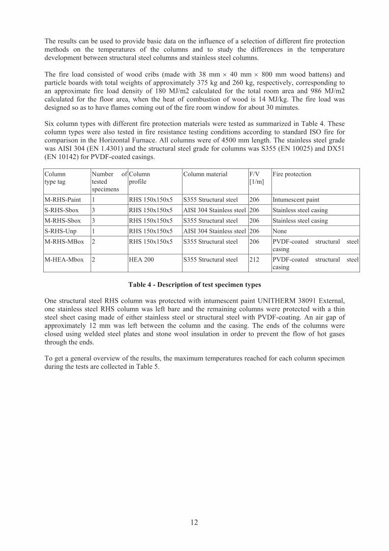
3.1.2 Tests performed by CTICM
A series of 6 experimental tests has been performed by CTICM within the framework of the research, in
order to study the effect of wind on external flames and on the heating of external elements. These
experiments have been carried out using a calorimeter hood described in Figure 3.
Plenum pre chamber
Blowing wall
Guide
Ventilator
Side view Plan view
14

Figure 3 - Overview of experimental tests (3 and 4) performed by CTICM
The fire load was made of wood cribs (leading to natural fire) and the same compartment was used for
each test. This one was made of cellular concrete. A ventilator and a plenum pre chamber constitute a
system of blowing used to simulate the effect of the wind.
The speed of the flow has been recorded using bidirectional probes [1, 2] at several locations. The
furnace’s dimensions are 5.40 m by 2.40 m, with an elevation of 2.50 m. A weigh platform is also used
to record the mass loss of the fire load. In order to simulate the presence of a second floor above the
compartment, the facade wall is higher than the ceiling.
Several fire loads and two kinds of opening have been employed. The main characteristics of the tests
are given in Table 6.
Test Fire load (kg) Opening (w*h) Wind speed (m/s)
1 940 1.80*1.40 0
2 450 1.80*1.40 0
3 600 1.80*1.40 0
4 620 1.80*1.40 2
5 620 1.40*1.40 6
6 620 1.40*1.40 10
Table 6 - Characteristics of the tests
The tests chronology is the following:
‚ Test 1: first test designed to check the experimental device, with only one element
‚ Test 2: second test, same as the first one but using a different fire load
‚ Test 3: reference test with all element placed and in blowing configuration but without wind
‚ Test 4: Blowing at 2 m/s but with bad quality of flow
‚ Test 5: Blowing at 6 m/s with a new blowing configuration
‚ Test 6: Blowing at 10 m/s with the same configuration
Facade view Plan view
15

Figure 4 - CTICM Test 1: One column located in front of the opening - Facade view
3.1.3 Tests performed by TNO
A fire compartment was built at the TNO Centre for Fire Safety for the purpose of carrying out full-
scale experiments of external flaming acting on unloaded steel structures. Four tests were carried out for
various compartment and opening dimensions (henceforth denoted Test 1 to Test 4).
Main objectives of the fire tests performed at TNO were:
‚ To study the effect of the compartment geometry on:
o the thermal action (compartment temperature and flame properties) on the external steel
structures
o the thermal response of the external steel structures
‚ To study the effect of the window geometry on the thermal action and thermal response
‚ To compare the measured thermal actions with available theoretical models
‚ To provide experimental data for verification of numerical models of the thermal response of
hollow core steel columns filled with concrete
In order to systematically study the effect of the compartment and window geometry only one
parameter was changed per test, with the external structures fixed on the same position (in front of the
facade with the windows) during all four tests. Unprotected steel profiles and composite (hollow core
steel section filled of concrete) were used closed to the opening for measuring the temperature reached
in the column.
The following parameter variation was carried out:
‚ Test 1: short compartment with one wide window of standard height
‚ Test 2: short compartment with two small windows of standard height
‚ Test 3: deep compartment with two small windows of standard height
16
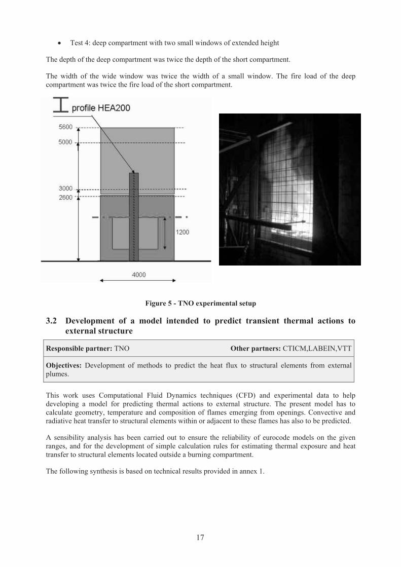
‚ Test 4: deep compartment with two small windows of extended height
The depth of the deep compartment was twice the depth of the short compartment.
The width of the wide window was twice the width of a small window. The fire load of the deep
compartment was twice the fire load of the short compartment.
Figure 5 - TNO experimental setup
3.2 Development of a model intended to predict transient thermal actions to
external structure
Responsible partner: TNO Other partners: CTICM,LABEIN,VTT
Objectives: Development of methods to predict the heat flux to structural elements from external
plumes.
This work uses Computational Fluid Dynamics techniques (CFD) and experimental data to help
developing a model for predicting thermal actions to external structure. The present model has to
calculate geometry, temperature and composition of flames emerging from openings. Convective and
radiative heat transfer to structural elements within or adjacent to these flames has also to be predicted.
A sensibility analysis has been carried out to ensure the reliability of eurocode models on the given
ranges, and for the development of simple calculation rules for estimating thermal exposure and heat
transfer to structural elements located outside a burning compartment.
The following synthesis is based on technical results provided in annex 1.
17
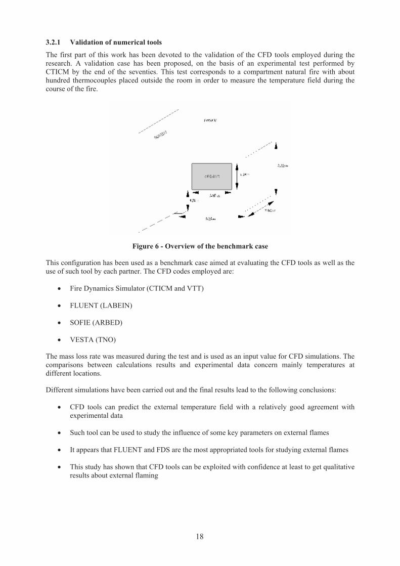
3.2.1 Validation of numerical tools
The first part of this work has been devoted to the validation of the CFD tools employed during the
research. A validation case has been proposed, on the basis of an experimental test performed by
CTICM by the end of the seventies. This test corresponds to a compartment natural fire with about
hundred thermocouples placed outside the room in order to measure the temperature field during the
course of the fire.
Figure 6 - Overview of the benchmark case
This configuration has been used as a benchmark case aimed at evaluating the CFD tools as well as the
use of such tool by each partner. The CFD codes employed are:
‚ Fire Dynamics Simulator (CTICM and VTT)
‚ FLUENT (LABEIN)
‚ SOFIE (ARBED)
‚ VESTA (TNO)
The mass loss rate was measured during the test and is used as an input value for CFD simulations. The
comparisons between calculations results and experimental data concern mainly temperatures at
different locations.
Different simulations have been carried out and the final results lead to the following conclusions:
‚ CFD tools can predict the external temperature field with a relatively good agreement with
experimental data
‚ Such tool can be used to study the influence of some key parameters on external flames
‚ It appears that FLUENT and FDS are the most appropriated tools for studying external flames
‚ This study has shown that CFD tools can be exploited with confidence at least to get qualitative
results about external flaming
18

3.2.2 Study of main parameters affecting external flames characteristics
The study of several important parameters affecting external flames characteristics has been performed
in order to check if the current models take them correctly into account. The use of CFD makes it
possible to study such particular effects with a good accuracy. Some experimental tests also allowed to
verify numerical results and to conclude about the need to modify current Eurocode models.
The flames are described using several parameters characterizing their shape, the temperature, the
absorption and the convection coefficient within them. The external flame zone is by convention the
area of space outside the room where the temperature exceeds 500 °C. The temperature is supposed to
be constant through the section of the flame and the absorption and convection coefficients are
supposed to be constant within the flame. Although the absorption coefficient depends on the nature of
fuel and on the conditions of ventilation, the use of a value close to 0.3 is recommended. The
convective coefficient is based on the heat release rate of the fire and the dimensions of the structural
element.
3.2.2.1 Effect of opening
The opening has an effect on the incoming air flux as well as external flames characteristics
(dimensions and temperature inside). The multi-openings configuration is of interest because many
buildings present such openings.
Several CFD simulations have shown that the incoming air flux can be estimated by the classical
approach
HAma 5.0?% ( 1)
This relation is only valid when the opening is relatively small compared to the façade. When the
opening occupies all the frontage of the burning compartment, it is recommended to multiply the
previous result by 0.6. A linear decrease according to the percentage of the opening compared to the
facade is proposed. This relation starts from 1 when the opening is 80% of the facade and is equal to 0.6
when the opening occupies 100% of the facade.
The dimensions of external flames also depend on the shape of the opening. CFD simulations have
shown that the current approach used in Eurocode seems acceptable to estimate flames dimensions from
opening ones, even in transient conditions.
On the other hand, the temperature distribution along the axis of external flames is not strongly
modified by the opening width in CFD calculations, contrary to the Eurocode assumption.
The multi-opening configuration seems correctly taken into account in Eurocode model when the
openings are similar in shape and located at the same level. This is not so obvious when very different
openings are involved. In this case, it is difficult to provide an estimation of the external flames
characteristics. The use of a zone model is then recommended, in order to know the condition of
ventilation for each opening.
A test series performed by TNO has also been used to validate the trends deduced from the numerical
simulations.
3.2.2.2 Effect of fuel
The fuel has obviously an important effect on external flames. Firstly, the fuel release rate resulting
from the pyrolysis of the fire load has a determining influence on the quantity of unburnt fuel gases
leaving the room through the opening. So, the external flames closely depend on that parameter.
Secondly, the nature of the fuel can play an important part on the characteristics of external flames.
The effect of fuel release rate is significant on incoming air mass flux by reducing it. The recommended
correlation is then
19
fuela mHAm %% 5.05.0 /? ( 2)
This outcome can be important only if the fuel release rate takes very high values compared to the
opening factor.
The main effect of fuel release rate on external flames is to increase their length. It is useful to introduce
the global equivalence ratio (GER):
air
fuel
airfuelm
mrGER
%
%/? ( 3)
This ratio represents the amount of fuel produced by pyrolysis in comparison with the amount of
incoming air into the room. It is theoretically greater than 1 when the fire is ventilation controlled. It is
theoretically lower than 1 when the fire is fuel controlled. When the GER is unity, combustion takes
place in stoichiometric conditions. CFD calculations and current Eurocode model are in relatively good
agreement to conclude that the overall flames length is linked to the GER by a linear relation. This can
be written
]40
)800;0max(65.1;5.0max[
/-©?
TGER
h
X ( 4)
X is the length of the flames, h is the opening height and T is the average temperature within the room.
Other dimensions such as flames width or flames depth (horizontal projection) are assumed to be
correctly estimated by current Eurocode model. In other words, the latter expression can be converted
into an expression for the flame height above the upper part of the opening.
The temperature along the axis of the external flame takes a different form according to the GER. The
Eurocode model gives coherent results only for relatively high values of GER. When the GER is low,
the temperature decrease approaches the results corresponding to external plumes without strong
flames. The temperature decreases like power -1 of the position on the axis. When the GER is more
important, the decrease follows rather a power -1/2 law.
To conclude, the Eurocode correlation concerning temperature along flame axis seems realistic only for
ventilation controlled fires, for which the GER is much greater than unity. During the growing phase of
the fire, this relation underestimates the decrease of temperature.
According to the numerical results, it is recommended to use the modified relation
));max(
027.01)(()(,
0,
stfuelfuel
afazmm
wlTTTlT
%%
©//-? ( 5)
In this relation, stfuelm ,% is the fuel flow rate corresponding to a unit GER.
The distribution of the fire load has been investigated using CFD. Numerical simulations have been
performed in order to assess the effect of the localization of the fuel emitting surfaces on the external
flames. Several configurations have been studied and are presented in annex 1. The conclusion drawn
from this work is that it is possible to systematically place the fire load near the opening in order to
predict external flames characteristics. This assumption seems to lead to safe conditions for external
elements. This is interesting especially when the compartment is very large compared to its opening. It
will be shown further that it is also possible to reduce the size of the compartment in such case. Thus, it
might be possible to extend the application of results from cubic compartment to long enclosures having
the same opening. So, the conclusion drawn about the fire load distribution is important when dealing
with large compartment.
20

Most often, experimental tests for the study of external flames use wood cribs as fire load. However,
there is an increasing use of plastics for furniture or coatings. So, we might wonder about the effect of
the nature of fuel on the characteristics of the produced flames. It is well known that a fire can reach
higher reaction rates with a non cellulose fuel than with wood cribs. Plastics can continue to produce
combustible elements, even in a very fuel rich environment. In order to study the effect of the nature of
the fuel, several numerical simulations have been performed. The conclusion of this work is that the use
of the global equivalence ratio makes it possible to estimate external flames length in the same way for
non cellulosic fuels or for wood cribs. Indeed, the correlation between GER and flame length remains
quite unchanged. The nature of the fuel has an influence on the amount of air incoming into the room.
The consequence is that higher heat release rates inside can be achieved with fuels having high
stoichiometric ratio. The average temperature is thus higher and the external flames seem longer
because they are defined by temperature.
3.2.2.3 Effect of compartment characteristics
The study of modern buildings raises the problem of the fire development in large enclosures. This
configuration thus constitutes an important case usually met in practice. Two different effects have been
numerically studied here: the case of a long compartment and the case of a wide compartment.
Comparisons have been made with a reference cubic shaped compartment. The dimensions of that latter
compartment are linked to the dimensions of the opening.
It appeared that the problem is not the same for the two configurations. The long, corridor-like,
compartment leads to external temperature field very close to the temperature field resulting from the
cubic shape compartment. The flows are also very similar between the two compartments. The entering
air can’t reach the rear of the long compartment, due to a strong recirculation established there. Indeed,
it seems that all combustion processes take place near the opening for the long compartment, quite at
the same location as for the cubic compartment. So, we can conclude that the depth of the compartment
has no sensible effect on external fields. These calculations show that in these cases the external
conditions are very lightly related to the compartment geometry.
In the wide compartment, the situation is somewhat different. It seems that the entering air manages to
reach side volumes more easily. It results in a better mixing especially in the upper part of the
compartment, which suggests that the temperature field is relatively homogeneous there. A reduction of
the flame length has been shown, mainly due to the difference in average temperature of gases
contained in the compartment.
By combining the results concerning the distribution of the fire load with the present results, the
following conclusion can be drawn. The geometry of the compartment has a different influence
according to the width on depth ratio. The long compartment leads to almost the same external flames
as an equivalent cubic shaped compartment, whatever the distribution of the fire load on the ground.
The configuration of a wide compartment is more complicated. It leads to truly three-dimensional
flows, which involves more important thermal losses because the exposed surface to hot gases is
increased compared to the cubic compartment. In all the cases, it seems that the characteristics of the
flames emerging from the cubic compartment leads to slightly overestimate thermal actions to external
members. This observation is important because it makes it possible to justify the use of an equivalent
compartment of reduced size for the analysis of large buildings.
The effect of wall thermal properties has also been investigated. Two numerical simulations have been
exploited with two values of thermal conductivity in order to study the influence of the thermal losses
through the walls on external flames characteristics. Obviously, the wall thermal properties result in a
different average temperature within the room.
This study has shown that the length of the external flames follows well the linear dependence with the
GER already established, whatever the properties of walls. The effect of increasing the temperature of
gases contained in the room thus results in a lengthening of the flames. So, the corresponding curve is
only translated. It is noticed that the values estimated by Eurocode model are comparable with the
simulations results but they seem a little bit under estimated in the case of insulating walls.
21
3.2.2.4 Effect of external obstructions
Two kinds of external obstruction have been studied. The first one is the presence of a prolongation of
the facade above the opening, whereas the second one is the presence of a balcony. The prolongation of
the facade above the opening exerts an influence on the flames shape by restricting the air entrainment
into them. So, the horizontal projection is strongly modified. The flames are brought back to the facade
when there is a wall above the opening, whereas they extend more easily without this wall. This
behaviour has been reproduced by numerical simulation and results are in relatively good agreement
with current Eurocode model. The main conclusion is that the shape of the external flames depends on
the opening geometry mainly when there is a wall above.
The presence of balconies is also an important parameter to take into account. It is assumed here that
the balconies are fire proof and completely prevent the flames to circumvent them on both sides. The
simulations have shown that, in the presence of a balcony, the temperature decrease along the flame
axis is modified, contrary to the recommendations of Eurocode model. Indeed, it seems that the
temperature remains roughly constant below the balcony. The behaviour of the external flames at the
edge of the balcony seems to be similar to the behaviour of external flames without prolongation of the
frontage, whereas the Eurocode model suggests that the flame "pulls back" over the balcony slab
towards the wall of the building. The agreement between Eurocode model and CFD concerning flame
length seems to be sufficiently good, and also the temperatures seem to decrease very quickly after the
hot gases are released from under the balcony and reach the level predicted by Eurocode model at the
end of the flame. Only the balcony's lower surface is subjected to higher temperatures than those
predicted by the Eurocode model, which places it on the unsafe side for this case. However, on the basis
of the available data, it is difficult to make a very accurate estimate of the temperature under the
balcony in all practical cases. Therefore a suggestion was formulated so that it will lead to conservative
results. It consists on keeping the temperature constant below the balconies (see annex 1).
3.2.2.5 Effect of wind
Almost all buildings are subjected to non negligible wind speeds in normal conditions of use. The
interaction of the flows generated by wind with the roughness of the ground modifies the velocity field
close to the ground by reducing its intensity. On the other hand, the openings located high are likely to
be subjected to more important winds. With the presence of strong winds, the external flames are
deviated and stretched by the external flow. There is also an effect on the existing flows through the
opening of the compartment, which can have an influence on the combustion reactions inside.
An experimental study of wind affect has been carried out by CTICM. A series of six tests using
different wind speeds have be performed using natural wood cribs fire in a compartment. These tests
have allowed investigating the effect of wind on external flames shape as well as on heat release rates
achieved within the compartment. The heating and cooling of columns located outside the room as a
function of wind speed have also been emphasized.
A complementary numerical study has revealed the main features observed during the tests. In
particular, the effect of external flow on the velocity field at the opening has been highlighted. Indeed, it
seems that the forced flow restricts the air intake in the compartment, and thus disturbs the mechanisms
of combustion within it. So, the blowing significantly restricts the heat release rate of the fire. This
point has been established experimentally and numerically.
In fact, the existence of a cross-wind involves a significant disturbance of the flow of air entering the
compartment which can certainly modify the fire development. Consequently, the heat release rate of
the fire may be less important. This would lead to less severe conditions outside the room. In addition,
the cooling of the external elements by convection seems enhanced by the wind.
22
Finally, it appears that only low speeds of cross-wind have a little effect little on the fire. So, the choice
a low wind speed constitutes a priori a safe assumption. In this case, the effect on external flames shape
remains moderate. Thus, it seems that the approximation of a deviation of 45° made in the Eurocode
model is sufficiently safe, even it is not fully realistic. As it has been shown experimentally, the flame
shape should be larger than the width of the opening. Thus the 45° deflection allows taking into account
the oscillation of the flame geometry around the average width which is equal to the opening width
according to the eurocode model.
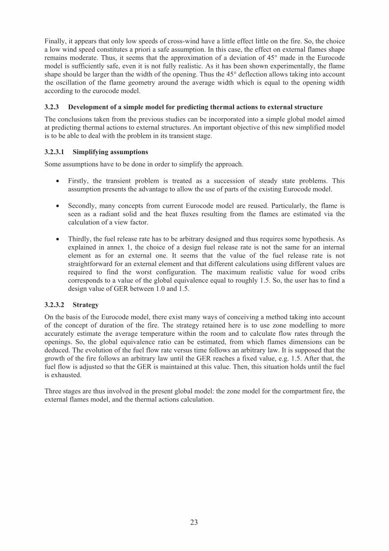
3.2.3 Development of a simple model for predicting thermal actions to external structure
The conclusions taken from the previous studies can be incorporated into a simple global model aimed
at predicting thermal actions to external structures. An important objective of this new simplified model
is to be able to deal with the problem in its transient stage.
3.2.3.1 Simplifying assumptions
Some assumptions have to be done in order to simplify the approach.
‚ Firstly, the transient problem is treated as a succession of steady state problems. This
assumption presents the advantage to allow the use of parts of the existing Eurocode model.
‚ Secondly, many concepts from current Eurocode model are reused. Particularly, the flame is
seen as a radiant solid and the heat fluxes resulting from the flames are estimated via the
calculation of a view factor.
‚ Thirdly, the fuel release rate has to be arbitrary designed and thus requires some hypothesis. As
explained in annex 1, the choice of a design fuel release rate is not the same for an internal
element as for an external one. It seems that the value of the fuel release rate is not
straightforward for an external element and that different calculations using different values are
required to find the worst configuration. The maximum realistic value for wood cribs
corresponds to a value of the global equivalence equal to roughly 1.5. So, the user has to find a
design value of GER between 1.0 and 1.5.
3.2.3.2 Strategy
On the basis of the Eurocode model, there exist many ways of conceiving a method taking into account
of the concept of duration of the fire. The strategy retained here is to use zone modelling to more
accurately estimate the average temperature within the room and to calculate flow rates through the
openings. So, the global equivalence ratio can be estimated, from which flames dimensions can be
deduced. The evolution of the fuel flow rate versus time follows an arbitrary law. It is supposed that the
growth of the fire follows an arbitrary law until the GER reaches a fixed value, e.g. 1.5. After that, the
fuel flow is adjusted so that the GER is maintained at this value. Then, this situation holds until the fuel
is exhausted.
Three stages are thus involved in the present global model: the zone model for the compartment fire, the
external flames model, and the thermal actions calculation.
23

Figure 7 - Main steps in the global model
3.2.3.3 Sub models description
3.2.3.3.1 Zone model for compartment fire
Any zone model able to simulate fully developed fire can be used to estimate the evolution of the
temperature within the compartment. This model should allow calculating the GER and the flowing
rates through the opening.
3.2.3.3.2 External flame model
Concerning the external flames description, the Eurocode model can be used with the following
arrangements:
The overall length of the flames X is given by the correlation (T in °C)
]40
)800;0max(65.1;5.0max[
/-©?
TGER
h
X ( 6)
This value is then employed to calculate the flame height above to top of the corresponding opening.
The temperature along the axis of the flame follows the relation
));max(
027.01)(()(,
0,
stfuelfuel
afazmm
wlTTTlT
%%
©//-? ( 7)
In this expression, stfuelm ,% is the fuel flow rate corresponding to a unit GER.
3.2.3.3.3 Heat flux calculation
The Eurocode approach is conserved. The calculation of heat flux is done by considering the view
factor between the solid flame and the considered target. As a first approximation, parallelepipedal
shapes from Eurocode model flames are reused.
3.2.3.4 Global model validation
A comparison between model predictions and experimental measurement is given in annex 1. This
comparison shows that the simplified model achieve a relatively good agreement with experimental
data despite its simplicity. This work also reveals that an error on the flame dimension can obviously
have a significant effect on local temperature value.
On the whole, it is interesting to note that the current Eurocode model can be used in transient state
without much modification of its sub-models.
24
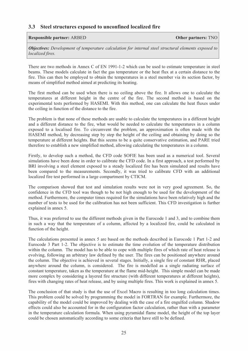
3.3 Steel structures exposed to unconfined localized fire
Responsible partner: ARBED Other partners: TNO
Objectives: Development of temperature calculation for internal steel structural elements exposed to
localized fires.
There are two methods in Annex C of EN 1991-1-2 which can be used to estimate temperature in steel
beams. These models calculate in fact the gas temperature or the heat flux at a certain distance to the
fire. This can then be employed to obtain the temperatures in a steel member via its section factor, by
means of simplified method aimed at predicting its heating.
The first method can be used when there is no ceiling above the fire. It allows one to calculate the
temperatures at different height in the centre of the fire. The second method is based on the
experimental tests performed by HASEMI. With this method, one can calculate the heat fluxes under
the ceiling in function of the distance to the fire.
The problem is that none of these methods are usable to calculate the temperatures in a different height
and a different distance to the fire, what would be needed to calculate the temperatures in a column
exposed to a localised fire. To circumvent the problem, an approximation is often made with the
HASEMI method, by decreasing step by step the height of the ceiling and obtaining by doing so the
temperature at different heights. But this seems to be a quite conservative estimation, and PARE tried
therefore to establish a new simplified method, allowing calculating the temperatures in a column.
Firstly, to develop such a method, the CFD code SOFIE has been used as a numerical tool. Several
simulations have been done in order to calibrate the CFD code. In a first approach, a test performed by
BRI involving a steel element exposed to a steady localized fire has been simulated and results have
been compared to the measurements. Secondly, it was tried to calibrate CFD with an additional
localized fire test performed in a large compartment by CTICM.
The comparison showed that test and simulation results were not in very good agreement. So, the
confidence in the CFD tool was though to be not high enough to be used for the development of the
method. Furthermore, the computer times required for the simulations have been relatively high and the
number of tests to be used for the calibration has not been sufficient. This CFD investigation is further
explained in annex 5.
Thus, it was preferred to use the different methods given in the Eurocode 1 and 3, and to combine them
in such a way that the temperature of a column, affected by a localized fire, could be calculated in
function of the height.
The calculations presented in annex 5 are based on the methods described in Eurocode 1 Part 1-2 and
Eurocode 3 Part 1-2. The objective is to estimate the time evolution of the temperature distribution
within the column. The model has to be able to cope with multiple fires of which rate of heat release is
evolving, following an arbitrary law defined by the user. The fires can be positioned anywhere around
the column. The objective is achieved in several stages. Initially, a single fire of constant RHR, placed
anywhere around the column, is considered. The fire is modelled as a single radiating surface of
constant temperature, taken as the temperature at the flame mid-height. This simple model can be made
more complex by considering a layered fire structure (with different temperatures at different heights),
fires with changing rates of heat release, and by using multiple fires. This work is explained in annex 5.
The conclusion of that study is that the use of Excel Macro is resulting in too long calculation times.
This problem could be solved by programming the model in FORTRAN for example. Furthermore, the
capability of the model could be improved by dealing with the case of a fire engulfed column. Shadow
effects could also be accounted for in the configuration factor calculation, rather than with a parameter
in the temperature calculation formula. When using pyramidal flame model, the height of the top layer
could be chosen automatically according to some criteria that have still to be defined.
25

3.4 Thermal response of bare and composite steel structures
Responsible partner: LABEIN Other partners: ARBEB, CTICM,TNO
Objectives: Development of temperature calculation methods for bare and composite external
elements.
The current Eurocode model of heat transfer to external steel structures is depicted in the annex B of the
EN 1993 – 1 – 2. This model takes as simplified inputs flame shape and properties which are defined in
the annex B of the EN 1991 – 1 – 2. The main features of the heat transfer model to external steel
structures are the following:
‚ It uses steady state approach: there is no time evolution of the temperature.
‚ The calculation procedure is different in case of the profile being engulfed or not, to account for
the differences in heat transfer due by radiation and convection.
‚ It considers a constant temperature within the section.
‚ Heat flux is calculated on a bounding box around the profile. Therefore shadow effects are not
accounted for.
‚ Composite sections are not considered.
So, a new model has been developed to tackle with these limitations. The proposed new model features
are:
‚ Transient calculation method allowing calculating temperature time evolution.
‚ For open sections, it is allowed to calculate heating of webs and flanges independently.
‚ For open sections, it is allowed to consider shadow effect in the heating of webs and flanges.
‚ It is also allowed to calculate radiation heat transfer between parts of the sections (flanges and
webs)
3.4.1 Model description
The model is based on the current model of Eurocode 3 with some modifications. For example, heat
transfer within structural members is treated as a 2D calculation.
The radiation from the fire compartment is calculated using the fire compartment temperature
evolution. The openings are considered as emitting surfaces at the temperature of the fire compartment
and a view factor need to be calculated. One of the main new features of the present model is the ability
to account for shadow effect in open sections concerning radiation from openings and, for not engulfed
members, concerning radiation from flames. Indeed, in the Eurocode model, heat flux is simply
calculated on four sides of a bounding box around the profile. In the present model, radiation heat
transfer is calculated from any emitting surface to the part of the receiving surface that effectively
receives radiation, by considering shadow effect. Hence, radiation is calculated in every face of the
parts of the open section.
It was shown by calculations that supposing that the whole radiation on the web or flange is estimated
by calculating the radiation received at the mid point instead of a series of points on it is a fair
assumption. So, the hypothesis of a simple point analytical method was acceptable, because the results
provided by that model are not very different from the results provided by more complex models.
26
Other modification of current Eurocode model is that the present model is able to take into account
radiation exchange between every surface (web and flanges). This refinement can be of interest for non-
engulfed members, when exposed flanges are exposed to much higher radiation fluxes than web and
non-exposed flange, leading to a redistribution of heat within the steel section enhanced by radiation.
The temperature evolution of webs and flanges is then obtained at every time step, by using the
expression from Eurocode 3 aimed at calculating steel temperature evolution as a function of heat flux.
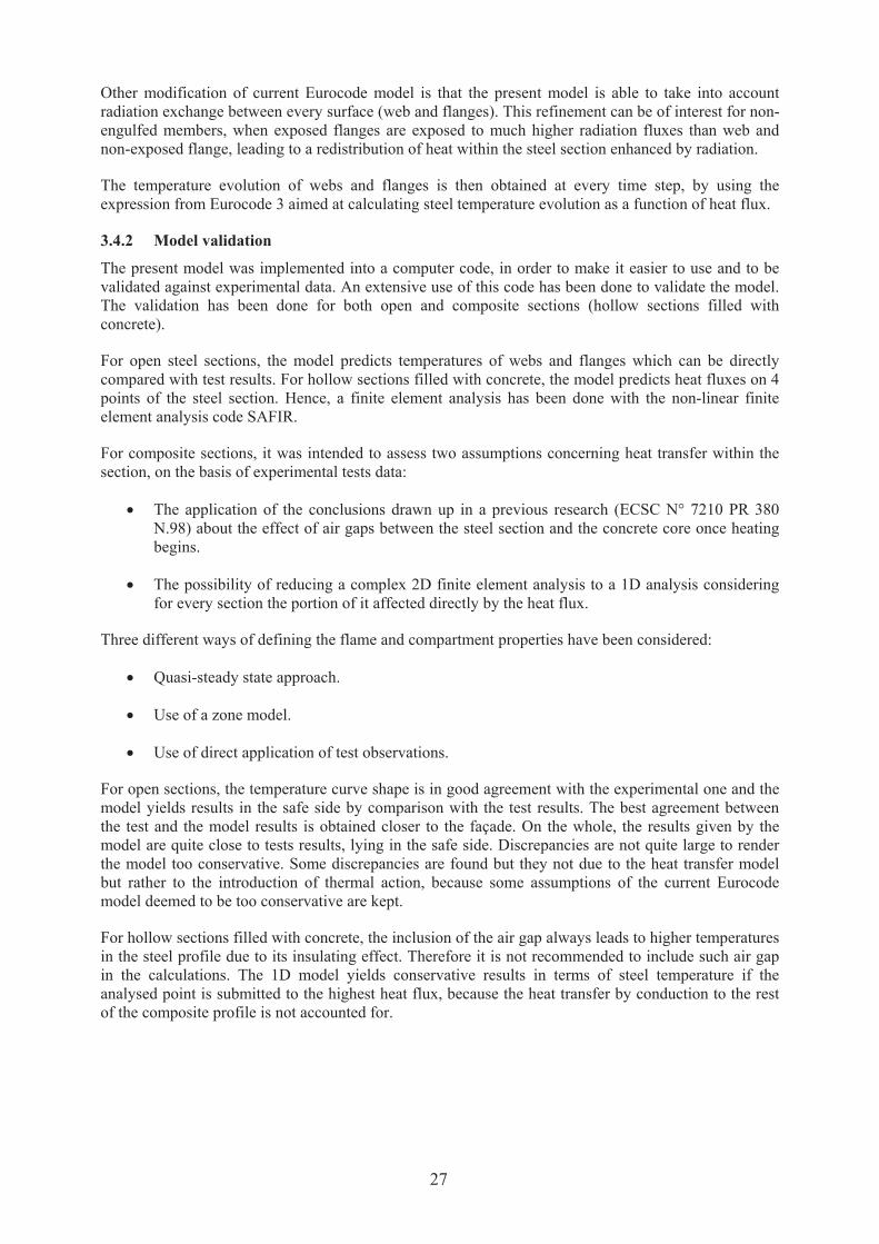
3.4.2 Model validation
The present model was implemented into a computer code, in order to make it easier to use and to be
validated against experimental data. An extensive use of this code has been done to validate the model.
The validation has been done for both open and composite sections (hollow sections filled with
concrete).
For open steel sections, the model predicts temperatures of webs and flanges which can be directly
compared with test results. For hollow sections filled with concrete, the model predicts heat fluxes on 4
points of the steel section. Hence, a finite element analysis has been done with the non-linear finite
element analysis code SAFIR.
For composite sections, it was intended to assess two assumptions concerning heat transfer within the
section, on the basis of experimental tests data:
‚ The application of the conclusions drawn up in a previous research (ECSC N° 7210 PR 380
N.98) about the effect of air gaps between the steel section and the concrete core once heating
begins.
‚ The possibility of reducing a complex 2D finite element analysis to a 1D analysis considering
for every section the portion of it affected directly by the heat flux.
Three different ways of defining the flame and compartment properties have been considered:
‚ Quasi-steady state approach.
‚ Use of a zone model.
‚ Use of direct application of test observations.
For open sections, the temperature curve shape is in good agreement with the experimental one and the
model yields results in the safe side by comparison with the test results. The best agreement between
the test and the model results is obtained closer to the façade. On the whole, the results given by the
model are quite close to tests results, lying in the safe side. Discrepancies are not quite large to render
the model too conservative. Some discrepancies are found but they not due to the heat transfer model
but rather to the introduction of thermal action, because some assumptions of the current Eurocode
model deemed to be too conservative are kept.
For hollow sections filled with concrete, the inclusion of the air gap always leads to higher temperatures
in the steel profile due to its insulating effect. Therefore it is not recommended to include such air gap
in the calculations. The 1D model yields conservative results in terms of steel temperature if the
analysed point is submitted to the highest heat flux, because the heat transfer by conduction to the rest
of the composite profile is not accounted for.
27

3.4.3 Conclusion
To conclude, the calculation of the steel temperature for open sections is made by considering the
flanges and web independently accounts for thermal gradients within the sections. This phenomenon
has been often observed during fire test of external steel members. The model is based on 3D
geometries for definition of configuration factors, but a 2D (reduced to 1D within the sections)
calculation is performed (no conduction along the profile axe is considered). For composite sections,
due to the low conductivity of concrete, larger gradients occur, and a finite element calculation is
addressed after calculation of heat fluxes on steel perimeter. A simplified 1D model has been checked,
and in some cases it is a good estimate of heat transfer within the section. If the peak temperature is the
target of the calculation, this approach trends to overestimate the temperature of hottest point of the
section, because it neglects the conduction to colder parts of steel perimeter. Otherwise, if a full
description of temperature rise is of interest, it tends to underestimate temperature rise of coldest points.
This leads to an overestimation of thermal gradient within the section. If the bending moment induced
by this thermal gradient sums up to the initial bending moment this result is not unsafe, otherwise, in
the first stages of the fire exposure, it leads to a reduction of the actual bending moment acting on the
member. This effect may be neglected once high temperatures are reached within the section so that
accidental induced actions do not play the main part in collapse mechanism.
3.5 Thermal response of protected steel structures
Responsible partner: CTICM Other partners: ARBEB, VTT
Objectives: Development of temperature calculation methods for protected external elements.
3.5.1 Introduction
The WP3 is intended to develop a model aimed at calculating the temperature of protected external
elements. Particularly, the case of interest is sections insulated by protection materials such as
intumescent coatings.
This work package also contains a method designed to obtain equivalent thermal characteristics of
intumescent coating, on the basis of test using conventional temperature curve. These values can then
be reemployed under natural fire conditions for external members to predict their heating. All the
results are shown in the appendix 3 report.
3.5.2 Use of intumescent coating
According to the study done in WP3, one can say that the use of intumescent coating for the protection
of external elements has to fulfil the following conditions:
‚ It has to be tested in order to know its fire resistance according to the European ISO Fire testing
conditions described in the ENV13381-4 for steel elements.
‚ It has to be submitted to aging test with different weather conditions.
‚ The fire resistance according to the European ISO Fire testing conditions described in the
ENV13381-4 for steel elements has to be checked, using the intumescent coating that has been
employed during the aging tests. The resulting performance has to be almost as good as the
initial fire resistance test.
‚ A natural fire tests with external elements has to be done to ensure that the intumescent coating
behaviour is acceptable with such kind of thermal actions.
3.5.3 Determination of equivalent thermal properties
Once the ability of intumescent coating to protect external members is verified, the equivalent thermal
properties can be determined with:
28

‚ The assumption of an equivalent thickness equal to 10 times the real applied thickness.
‚ The determination of the thermal properties using comparison with the:
o ISO Fire test results.
o Natural fire test results for external use.
There are several methods used to evaluate thermal properties, mainly based on a comparison between
the measured times to reach a certain design steel temperatures and calculation results. The various
assessment methods differ in the way the time to reach a certain design steel temperature is determined.
Nevertheless, the application of these ones is restricted to the context of standard fire. So, these thermal
properties are not valid for external structures.
The methodology developed by CTICM to have a better characterisation of thermal properties of the
intumescent materials is based on a parametric numerical study, using a finite element code. The
varying coefficients are the thermal conductivity and the specific heat. The principle of the parametric
study is to compare experimental and numerical results concerning temperature. This study permits to
determine the thermal conductivity and the specific heat of the intumescent product in order to obtain a
good correlation with all the experimental results. The conditions under which these characterisations
were carried out correspond to the normalized fire ISO 834. In order to take into account the expansion
effect of the intumescent coating during its heating, the method assumes that the thickness of the
coating is 10 times its initial value.
3.5.4 Validation
The numerical simulations are in good agreement with the thermocouple measurements, in particular
during the heating of the element. However, the cooling effect is not well simulated. But the focus is not
put on the decay of the fire. The maximum temperature and the time to reach it are the main parameters.
The following figure gives an example of comparison between prediction using equivalent thermal
properties and experimental data.
0
50
100
150
200
250
300
350
400
450
500
550
600
650
0 10 20 30 40 50 60Time (min)
Tem
pera
ture
(°C
)
thermocouple 1
thermocouple 2
numerical simulation
Figure 8 - Example of validation against experimental measurement
29
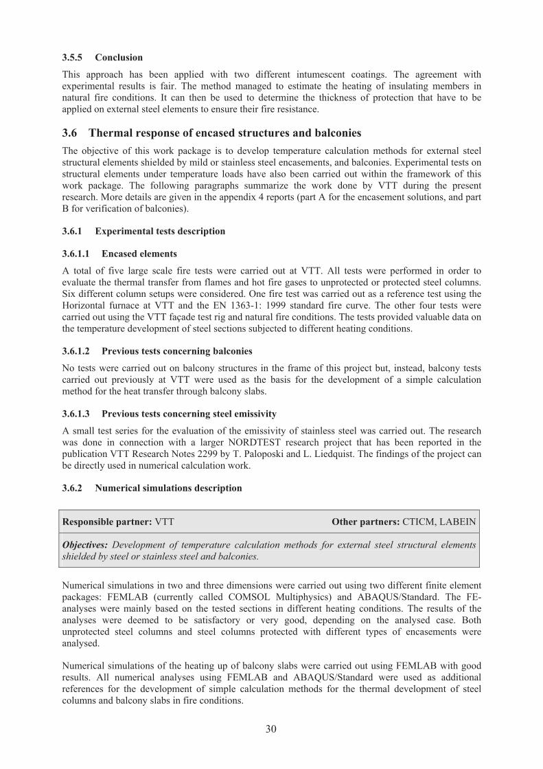
3.5.5 Conclusion
This approach has been applied with two different intumescent coatings. The agreement with
experimental results is fair. The method managed to estimate the heating of insulating members in
natural fire conditions. It can then be used to determine the thickness of protection that have to be
applied on external steel elements to ensure their fire resistance.
3.6 Thermal response of encased structures and balconies
The objective of this work package is to develop temperature calculation methods for external steel
structural elements shielded by mild or stainless steel encasements, and balconies. Experimental tests on
structural elements under temperature loads have also been carried out within the framework of this
work package. The following paragraphs summarize the work done by VTT during the present
research. More details are given in the appendix 4 reports (part A for the encasement solutions, and part
B for verification of balconies).
3.6.1 Experimental tests description
3.6.1.1 Encased elements
A total of five large scale fire tests were carried out at VTT. All tests were performed in order to
evaluate the thermal transfer from flames and hot fire gases to unprotected or protected steel columns.
Six different column setups were considered. One fire test was carried out as a reference test using the
Horizontal furnace at VTT and the EN 1363-1: 1999 standard fire curve. The other four tests were
carried out using the VTT façade test rig and natural fire conditions. The tests provided valuable data on
the temperature development of steel sections subjected to different heating conditions.
3.6.1.2 Previous tests concerning balconies
No tests were carried out on balcony structures in the frame of this project but, instead, balcony tests
carried out previously at VTT were used as the basis for the development of a simple calculation
method for the heat transfer through balcony slabs.
3.6.1.3 Previous tests concerning steel emissivity
A small test series for the evaluation of the emissivity of stainless steel was carried out. The research
was done in connection with a larger NORDTEST research project that has been reported in the
publication VTT Research Notes 2299 by T. Paloposki and L. Liedquist. The findings of the project can
be directly used in numerical calculation work.
3.6.2 Numerical simulations description
Numerical simulations in two and three dimensions were carried out using two different finite element
packages: FEMLAB (currently called COMSOL Multiphysics) and ABAQUS/Standard. The FE-
analyses were mainly based on the tested sections in different heating conditions. The results of the
analyses were deemed to be satisfactory or very good, depending on the analysed case. Both
unprotected steel columns and steel columns protected with different types of encasements were
analysed.
Numerical simulations of the heating up of balcony slabs were carried out using FEMLAB with good
results. All numerical analyses using FEMLAB and ABAQUS/Standard were used as additional
references for the development of simple calculation methods for the thermal development of steel
columns and balcony slabs in fire conditions.
Responsible partner: VTT Other partners: CTICM, LABEIN
Objectives: Development of temperature calculation methods for external steel structural elements
shielded by steel or stainless steel and balconies.
30

3.6.3 Model development description
3.6.3.1 Encased elements
Simple calculation methods were developed for the thermal analysis of steel columns that are
unprotected, or protected with thin steel encasements. The developed 1D-calculation method can be
used when both the structure and the fire exposure are cylindrically symmetric. This is also valid for
RHS-sections, which are not quite cylindrically symmetric. The developed 2D-calculation methods are
more general and can be used for CHS-, RHS-, H- and I-sections subjected to either symmetric or
asymmetric fire exposure.
The calculation methods were validated against test results and compared to finite element modelling
results. The methods were programmed using MATLAB and full instructions for their use have been
given.
3.6.3.2 Balconies
A simple 1D-calculation method for the thermal analysis of layered structures was developed. The
foremost application of the method is for layered steel sheet balcony slab structures, but the method can
be used for any layered structure, which can be approximated in 1D. The method was validated against
available balcony test results and finite element analyses. It was programmed using MATLAB and full
instructions for its use have been given.
Sensitivity analyses were carried out along the validation processes for all the above calculation models
within the essential ranges. Suitable material parameters and modelling practices for the attainment of
conservative results were established.
3.7 Methodology for evaluating the heating of external structures
The Eurocode model has been developed on the basis of empirical assumptions. Even if this model is
analytical, its use can be done by hand. Different software have been developed in many countries in
order to simplified its application restricted to unprotected steel structures from a steady state
assumptions.
One aim of the present project was to develop a method for transient condition in order to extend the
current model to protected steel structures or composite structures. The results of the method are the
determination of the thermal actions from the external flaming to the structural elements. Then,
methodology for determination of the thermal response of protected steel structure, composite structure
and encased steel structure has been developed.
When application has to be made, the verification of the fire stability for an unprotected steel structure
has to be made first.
If the fire stability is not achieved, several parameters may be changed to obtain the required fire
stability:
‚ the section of the structural element should be increased (increasing thus the critical
temperature)
‚ the geometry of the compartment should be modified, and mainly the opening closed to the
steel structure
‚ a protection or a composite section can be involved: then the transient method has to be used:
31

Structural design
Architectural design
Selection of scenarios
(compartement, openings)
Selection of structural element
Determination of the temperature
reached by the element ss
according EC3-1-2
Selections of the fire design-
thermal actions to stuctural
elements according EC1-1-2Calculations of the
Critical Temperature sc
according EC3 part 1.2
sc<ss
Possible modification
of the section
Fire stability verified
NO
YES
Application of the transient model
NO
Possible modification
of the position of
the structural elements
YES
Application of the transient model
NO
YES
Figure 9 - Steps to verify the fire stability of structural elements using the current eurocode model
An example of application of the method presented in the present chapter is given in the following
chapter.
3.7.1 Transient method for thermal actions
The transient method consists on the following steps:
‚ Step 1 : selecting design fire scenarios and design fires
‚ Step 2 : determining the thermal actions to the structural elements
‚ Step 3 : determining the thermal response of the structural elements
‚ Step 4 : determining the fire behaviour of the structural elements
The two main steps should be summarized by the following graphs giving the main data.
To determine the thermal actions to the structural elements, the first step (1) is similar than the current
Eurocode Model. Only additional recommendations have been given, by using two design-fires, the
first with a global equivalence ratio (GER) of 1, and the second with a GER of 1,5.
Then from these design-fires, the thermal actions have to be calculated according to the methodology
developed in the present project. In fact, three levels of complexity of the method are proposed as
mentioned in the following figure:
32
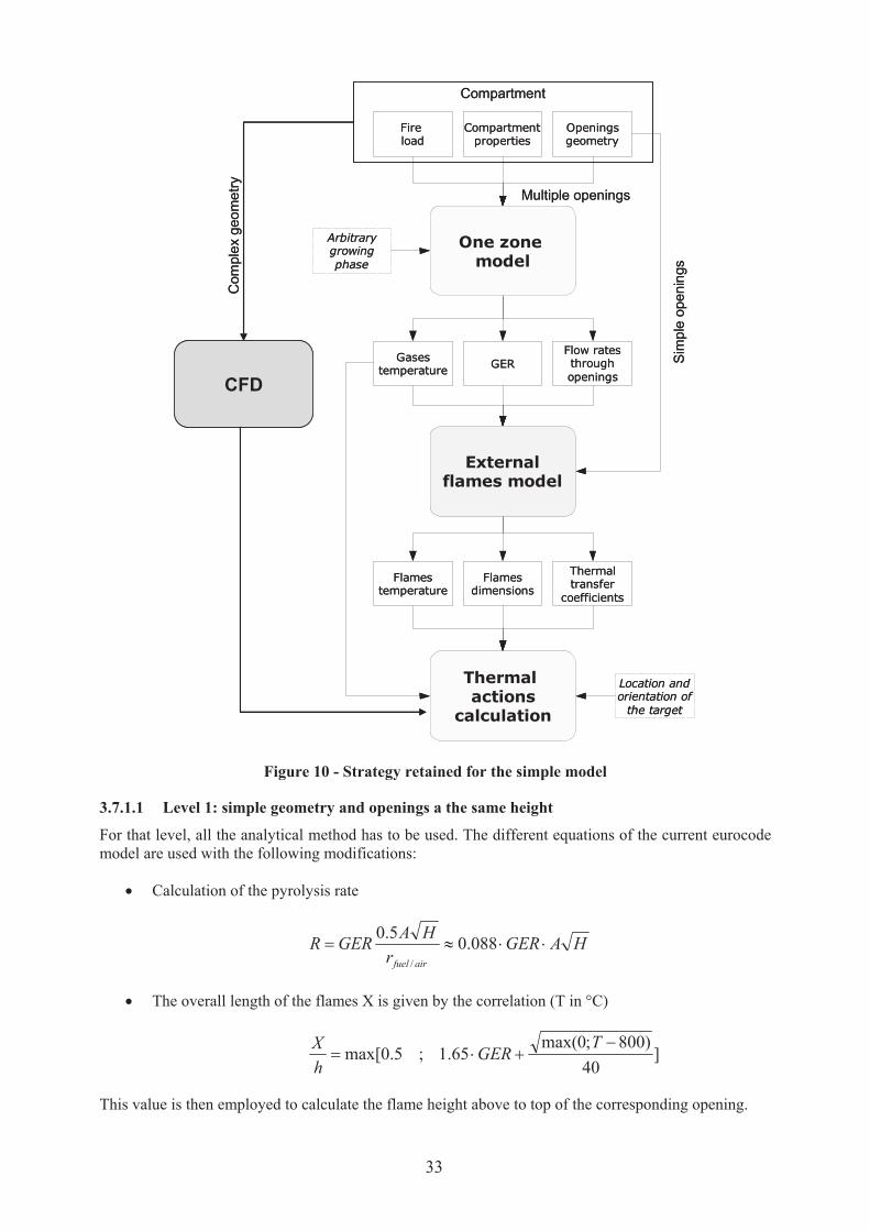
One zone
model
External
flames model
Thermal
actions
calculation
Openingsgeometry
Compartmentproperties
Fire load
Arbitrarygrowing phase
Gasestemperature
GERFlow rates through openings
Flames temperature
Flames dimensions
Thermal transfer
coefficients
Location and orientation of
the target
Sim
ple
open
ings
Multiple openings
Compartment
Com
ple
xgeo
me
try
CFD
Figure 10 - Strategy retained for the simple model
3.7.1.1 Level 1: simple geometry and openings a the same height
For that level, all the analytical method has to be used. The different equations of the current eurocode
model are used with the following modifications:
‚ Calculation of the pyrolysis rate
HAGERr
HAGERR
airfuel
©©…? 088.05.0
/
‚ The overall length of the flames X is given by the correlation (T in °C)
]
40
)800;0max(65.1;5.0max[
/-©?
TGER
h
X
This value is then employed to calculate the flame height above to top of the corresponding opening.
33

‚ The temperature along the axis of the flame follows the relation
));max(
027.01)(()(,
0,
stfuelfuel
afazmm
wlTTTlT
%%
©//-?
In this expression, stfuelm ,%
is the fuel flow rate corresponding to a unit GER.
‚ Using balconies needs to use the modification proposed in the present report and in the
appendix report 1 (WP1) and appendix report 4 part A describing the effect of a balcony
‚ Compared to the current eurocode model, shielding effect of the steel profiles may be taken into
account using the tools developed in the present research for H or I profiles
‚ The temperature inside the compartment is given by the parametrical fires of eurocode as a
function of time
From these applications, a thermal action is determined. This thermal action is then applied on
structural elements during the external flaming duration Te-f that can be assessed by:
Te-f =(Qf,d A)/ (R FHc)
where
Qf,d is the design fire load (MJ/m²)
A the surface of the compartment (m²)
R the pyrolysis rate (kg/s)
FHc is the net combustion heat (MJ/kg)
3.7.1.2 Level 2: multiple opening with different heights
This second level of complexity is the same application as the level 1, but a one zone model is used for:
‚ determining the temperature-time curve in the compartment with better accuracy than the
parametrical fires
‚ determining the neutral plane to define an equivalent opening according to the conditions of air
entrance and external flaming
3.7.1.3 Level 3: complex geometry and specific fluid flows
The third level is relevant to complexity of
‚ the geometry of compartment
‚ the structural elements
‚ the characteristics of the type of protection used (e.g. deflector)
In that conditions the fluid mechanisms can not be simplified, and a complete modelling of the external
flaming and its interaction with structural elements has to be made.
34

Figure 11 - Example of external columns protected by deflectors
Recommendations of the use of the CFD for that verification is given along the report, as for example
the use of two main design-fires defined by a GER of 1 for smaller thermal actions with a larger
duration, or a GER of 1.5 for larger thermal actions with a small duration.
3.7.2 Thermal response and mechanical behaviour
From the thermal actions as a function of time, the thermal response and mechanical behaviour has to
determine.
Methods for the thermal response of the 3 types of elements are given in the present report:
‚ hollow core steel sections filled of concrete, with or without rebars
‚ steel sections protected by intumescent coatings
‚ steel sections encased in a steel box
For the temperature distribution in the profile, the mechanical behaviour can be assessed with the
eurocode 3 part 1.2 “fire behaviour of steel structures” or eurocode 4 part 1.2 “fire behaviour of
composite structures (steel and concrete), or with a finite element model (FEM) when the temperature
distribution is not homogeneous or if the structural element is out of the scope or the application domain
of the eurocode.
3.8 Example of application of the methods developed during this project
3.8.1 Introduction
An example is treated now, in order to show an application of the methods developed within the
framework of the PR380 project. The case of a real building is used here to show how the simplified
methods can be involved to define a solution in a realistic context for which external members have to
be protected.
3.8.1.1 Building configuration
The considered building has 9 levels of 2.80 m height. Its facade is made of glazed frontage, so the
entire facade of each room can be opened during fire. The level studied here is composed of offices and
libraries. Compartment studied in level 1 is 30.0 m width and 23.0 m depth, whereas compartments of
level 2 to 4 are 23.0 m on 23.0 m.
35
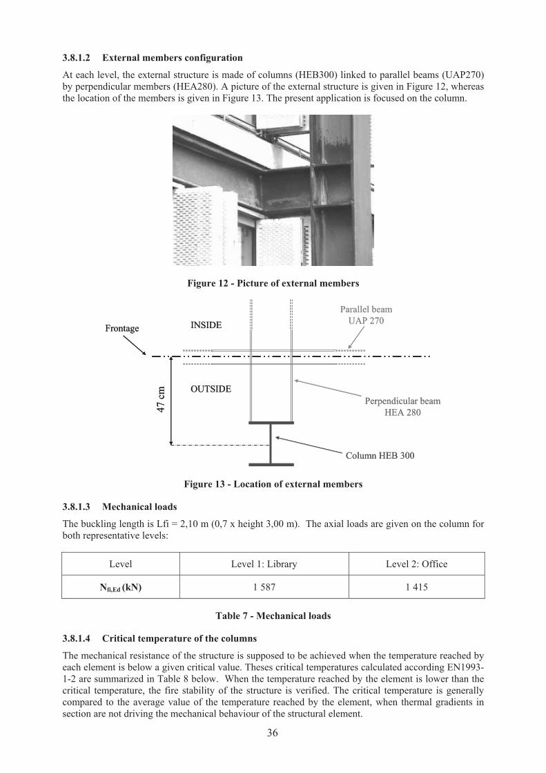
3.8.1.2 External members configuration
At each level, the external structure is made of columns (HEB300) linked to parallel beams (UAP270)
by perpendicular members (HEA280). A picture of the external structure is given in Figure 12, whereas
the location of the members is given in Figure 13. The present application is focused on the column.
Figure 12 - Picture of external members
Perpendicular beam
HEA 280
Parallel beam
UAP 270
Column HEB 300
Frontage INSIDE
OUTSIDE
47 c
m
Perpendicular beam
HEA 280
Parallel beam
UAP 270
Column HEB 300
Frontage INSIDE
OUTSIDE
47 c
m
Figure 13 - Location of external members
3.8.1.3 Mechanical loads
The buckling length is Lfi = 2,10 m (0,7 x height 3,00 m). The axial loads are given on the column for
both representative levels:
Level Level 1: Library Level 2: Office
Nfi,Ed (kN) 1 587 1 415
Table 7 - Mechanical loads
3.8.1.4 Critical temperature of the columns
The mechanical resistance of the structure is supposed to be achieved when the temperature reached by
each element is below a given critical value. Theses critical temperatures calculated according EN1993-
1-2 are summarized in Table 8 below. When the temperature reached by the element is lower than the
critical temperature, the fire stability of the structure is verified. The critical temperature is generally
compared to the average value of the temperature reached by the element, when thermal gradients in
section are not driving the mechanical behaviour of the structural element.
36

Level 1 Level 2
Critical temperature (°C) 563 727
Table 8 - Critical temperatures for external members
3.8.1.5 External members temperatures
3.8.1.5.1 Room geometry
A parametrical study has been performed to find the worst opening configuration concerning external
members. The conclusion of this study leads to the compartment geometry shown in Figure 14. Two
values of fire load density are used: 100 kg/m² representative of the library and 30 kg/m² of wood
representative of the office. The member is supposed to be located in the center of the opening: no fire
resistance mullion is defined in the building.
Figure 14 - Overview of the reference compartment
3.8.1.5.2 Heat fluxes to external elements
The application of eurocode model leads to the following results given in table 2. The axes are shown in
Figure 14.
fx+
(kW/m²)
fx-
(kW/m²)
fy+
(kW/m²)
fy-
(kW/m²)
fz+
(kW/m²)
fz-
(kW/m²)
T (°C)
Column 81.2 81.2 0.0 0.0 34.2 88.5 764
Table 9 - Heat fluxes and temperatures reached by unprotected members according to eurocode
method (fz- corresponds to the face facing the opening)
3.8.1.6 Fire stability of unprotected columns
Regards to the critical temperatures and the temperatures reached by the columns according the
Eurocode 3 part 1.2, it can be concluded that the columns are the level 3 are fire resistant and could stay
unprotected, while the columns at the level 1 and 2 are not and should be protected.
It is then proposed to apply the method and tools developed within the present research to design the
protection or chose new column section to be fire resistant, using an unsteady approach.
2.80 m
7.00 m
23.00 m
14.00 m
OPENING
MEMBER
y
x
z
37
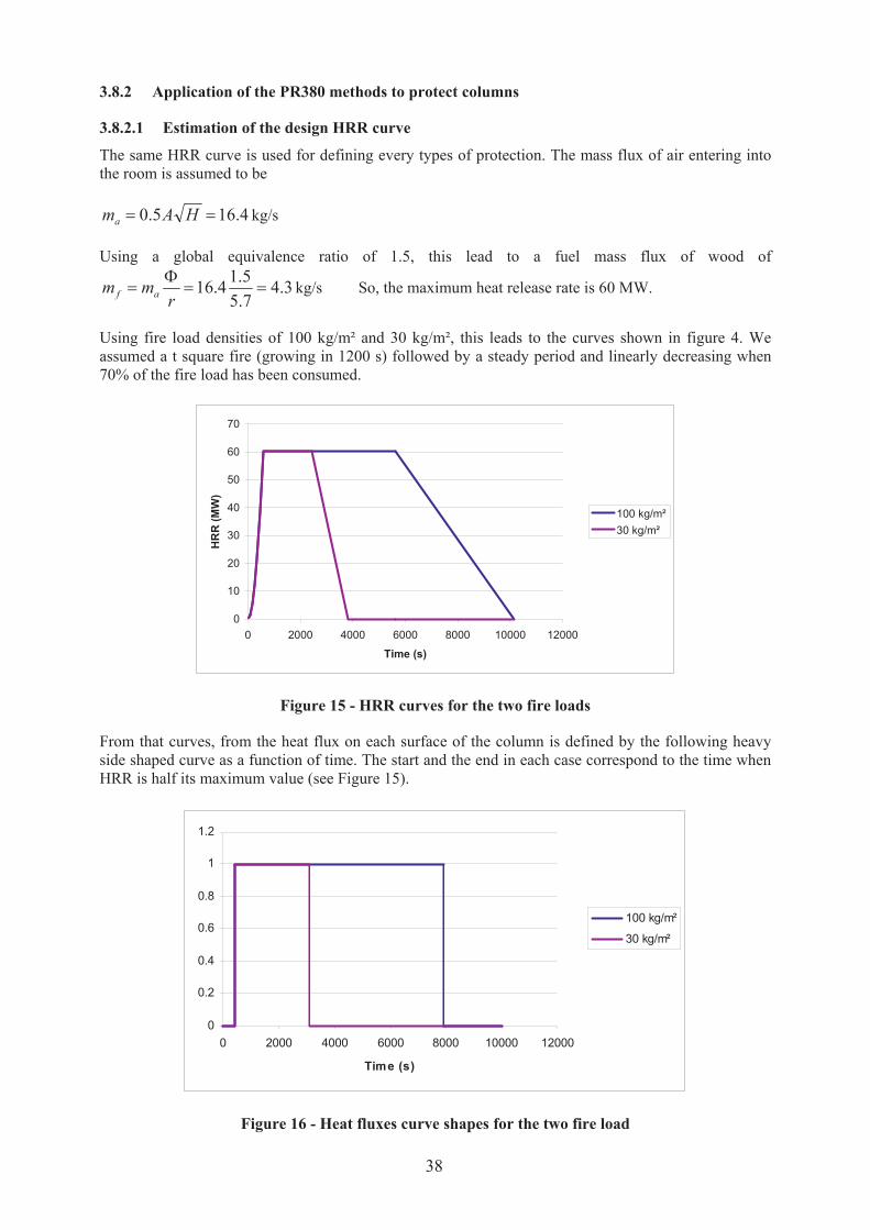
3.8.2 Application of the PR380 methods to protect columns
3.8.2.1 Estimation of the design HRR curve
The same HRR curve is used for defining every types of protection. The mass flux of air entering into
the room is assumed to be
4.165.0 ?? HAma kg/s
Using a global equivalence ratio of 1.5, this lead to a fuel mass flux of wood of
3.47.5
5.14.16 ??
H?
rmm af kg/s So, the maximum heat release rate is 60 MW.
Using fire load densities of 100 kg/m² and 30 kg/m², this leads to the curves shown in figure 4. We
assumed a t square fire (growing in 1200 s) followed by a steady period and linearly decreasing when
70% of the fire load has been consumed.
0
10
20
30
40
50
60
70
0 2000 4000 6000 8000 10000 12000
Time (s)
HR
R (
MW
)
100 kg/m²
30 kg/m²
Figure 15 - HRR curves for the two fire loads
From that curves, from the heat flux on each surface of the column is defined by the following heavy
side shaped curve as a function of time. The start and the end in each case correspond to the time when
HRR is half its maximum value (see Figure 15).
0
0.2
0.4
0.6
0.8
1
1.2
0 2000 4000 6000 8000 10000 12000
Time (s)
100 kg/m²
30 kg/m²
Figure 16 - Heat fluxes curve shapes for the two fire load
38
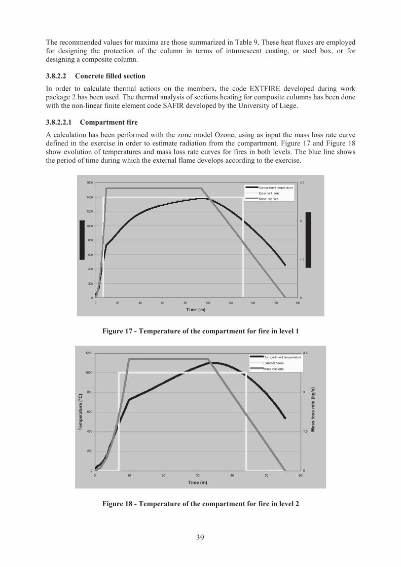
The recommended values for maxima are those summarized in Table 9. These heat fluxes are employed
for designing the protection of the column in terms of intumescent coating, or steel box, or for
designing a composite column.
3.8.2.2 Concrete filled section
In order to calculate thermal actions on the members, the code EXTFIRE developed during work
package 2 has been used. The thermal analysis of sections heating for composite columns has been done
with the non-linear finite element code SAFIR developed by the University of Liege.
3.8.2.2.1 Compartment fire
A calculation has been performed with the zone model Ozone, using as input the mass loss rate curve
defined in the exercise in order to estimate radiation from the compartment. Figure 17 and Figure 18
show evolution of temperatures and mass loss rate curves for fires in both levels. The blue line shows
the period of time during which the external flame develops according to the exercise.
0
200
400
600
800
1000
1200
1400
1600
0 20 40 60 80 100 120 140 160 180
T ime ( m)
0
1.5
3
4.5
Compar tment temper atur e
Exter nal f lame
Mass loss r ate
Figure 17 - Temperature of the compartment for fire in level 1
0
200
400
600
800
1000
1200
0 10 20 30 40 50 60
Time (m)
Tem
pera
ture
(ºC
)
0
1.5
3
4.5
Mass l
oss r
ate
(kg
/s)
Compartment temperature
External flame
Mass loss rate
Figure 18 - Temperature of the compartment for fire in level 2
39

3.8.2.2.2 Results for external members
3.8.2.2.2.1 Level 2: fire scenario in an office
The figure below shows the evolution of temperature within the flanges and web of the HEB 300 profile
in front of the office at the height of the soffit of the opening.
The peak temperature in the exposed flange is 576º C. If the Eurocode 3 part 2 is used to calculate
resistance of the sections it should be considered the highest temperature of the section. The critical
temperature (727 ºC) is higher than the peak temperature, so it results that the columns does not
collapse.
The steady state calculated in the exercise (blue line in Figure 19) is much higher than the transient one,
above the critical temperature, leading to conservative conclusions. The exposure time is not long
enough to make the profile reach the steady state temperature. To summarize, if a transient calculation
is done, the profile does not need to be protected with passive protection, because collapse does not
occur if the member remains unprotected.
0
100
200
300
400
500
600
700
800
0 10 20 30 40 50 60
T ime (m)
Steady - state temper atur e
Cr i tical temper atur e
Exposed f lange - Bar e HEB 300
Non exposed f lange - Bar e HEB 300
Web - Bar e HEB 300
Figure 19 - Temperatures within the HEB 300 profile in front of the office
3.8.2.2.2.2 Level 1: fire in a library
Figure 20 shows temperature evolution in flanges and web of the HEB 300 in front of the library. As
foreseen, the critical temperature is reached firstly in the exposed flange at 37 minutes and later in the
non-exposed flange and the web. So, a design of composite column is proposed as shown in Figure 21
to provide insulation to the steel section. A concrete partial encasement is proposed only for insulation
purposes not for structural resistance. The concrete is made of siliceous aggregate with content of 100
kg/ m3 of water.
40

0
100
200
300
400
500
600
700
800
900
0 20 40 60 80 100 120 140 160 180
Time (m)
Tem
pe
ratu
re (
ºC)
Steady - state temperature
Exposed flange - Bare HEB 300
Web - Bare HEB 300
Critical temperature
Non exposed flange - Bare HEB 300
Figure 20 - Evolution of temperature in the bare HEB 300 section for fire in the library
Figure 21 - Composite section design proposed for the HEB 300 section
Figure 22 shows a comparison of temperature evolution in the flanges and in the web for the bare HEB
section and for steel in the composite column.
0
100
200
300
400
500
600
700
800
900
0 20 40 60 80 100 120 140 160 180
Time (m)
Te
mp
era
ture
(ºC
)
Exposed flange - Encased HEB 300
Steady - state temperature
Exposed flange - Bare HEB 300
Web - Bare HEB 300
Critical temperature
Non exposed flange - Bare HEB 300
Non exposed flange - Encased HEB 300
Web - Encased HEB 300
Figure 22 - Comparison of temperature evolution in the steel section
41

Figure 23 shows a temperature distribution within the section at 110 minutes of exposure when the peak
temperature is reached in the exposed flange.
As a result of the concrete insulation, the exposed flange undergoes an increase of temperature by
comparison with the bare section. This is due to the fact that in the composite section, the concrete core
acts as a barrier that hinders the exposed flange to evacuate heat to the rest of the section. However the
non-exposed flange and the web reach much lower temperatures in the composite section than in the
bare section.
Figure 23 - Temperature distribution within the section at 110 minutes
If the simplified Eurocode 3 rules are used, the result is that the column collapses, because the higher
temperature is used to verify the stability. However, a great part of the section is under the critical
temperature.
As a conclusion, according to the current steady state approach of the Eurocode, the columns should be
protected with a passive fire protection in both cases. In case of the least severe fire it is demonstrated
that the bare section is capable to resist the full duration of the fire, because the steady temperature is
not reached, and peak temperature is lower than the critical one. In case of the most sever fire; the fire
resistance is 37 minutes. If the structure has to resist the full duration of the fire, it is proposed to encase
with concrete between flanges the column in the first three storeys. The insulation provided by this
solution results in lower temperatures in the web and the non-exposed flange that retains structural
stability.
3.8.2.3 Protected steel section
The heat fluxes curves given above in the definition of the exercise have been used as boundary
conditions for heat transfer calculation, using finite element modelling. This procedure is employed
here to find the thickness of the intumescent coating that has to be applied on the structure to prevent it
to reach its critical temperature. Two kinds of coatings are studied here.
3.8.2.3.1 Thermal properties of intumescent coatings
The apparent thermal properties of two kind of coating have been deduced from experimental tests as
described in annex 3. Using these values, several calculations can be performed to find the minimum
required thickness to ensure that the steel temperature stay below the critical temperature of the
considered element.
42
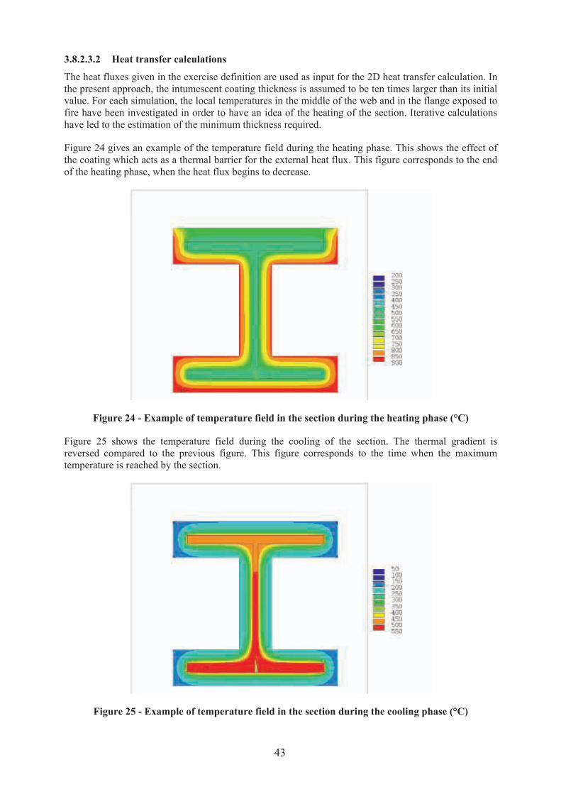
3.8.2.3.2 Heat transfer calculations
The heat fluxes given in the exercise definition are used as input for the 2D heat transfer calculation. In
the present approach, the intumescent coating thickness is assumed to be ten times larger than its initial
value. For each simulation, the local temperatures in the middle of the web and in the flange exposed to
fire have been investigated in order to have an idea of the heating of the section. Iterative calculations
have led to the estimation of the minimum thickness required.
Figure 24 gives an example of the temperature field during the heating phase. This shows the effect of
the coating which acts as a thermal barrier for the external heat flux. This figure corresponds to the end
of the heating phase, when the heat flux begins to decrease.
Figure 24 - Example of temperature field in the section during the heating phase (°C)
Figure 25 shows the temperature field during the cooling of the section. The thermal gradient is
reversed compared to the previous figure. This figure corresponds to the time when the maximum
temperature is reached by the section.
Figure 25 - Example of temperature field in the section during the cooling phase (°C)
43

3.8.2.3.3 Determination of the thickness of the coating
3.8.2.3.3.1 Level 1: Fire in a library
Several calculations have been performed with different values of coating thickness for this scenario
with the two coatings. The maximum temperatures reached by steel are given in Figure 26 and Figure
27.
1,76 mm 2 mm 2,5 mm
0
50
100
150
200
250
300
350
400
450
500
550
600
650
Maximum temperature
Flange (°C)
Web (°C)
2,5 mm 3 mm
0
50
100
150
200
250
300
350
400
450
500
550
600
Maximum temperature
Flange (°C)
Web (°C)
Figure 26 - Maximum temperatures reached
within the section for coating 1
Figure 27 - Maximum temperatures reached
within the section for coating 2
This study shows that a thickness of 2.5 mm for coating 1 and 3.0 mm for coating 2 is sufficient to
maintain the section below its critical temperature. Figure 28 gives an example of the evolution of
temperature within the section.
0
100
200
300
400
500
600
0 50 100 150 200 250 300 350 400
Time (min)
Flange
Web
Critical temperature
Figure 28 - Evolution of temperature during fire in a library in the section insulated with 2.5 mm
of coating 1 (°C)
44
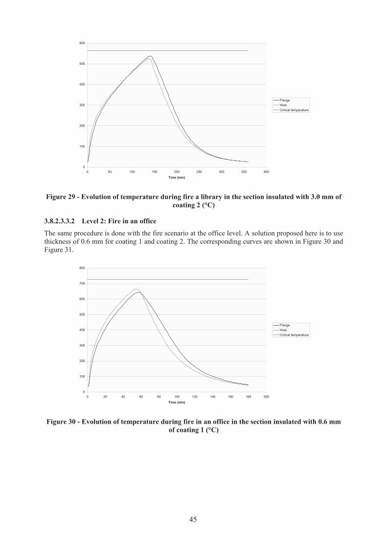
0
100
200
300
400
500
600
0 50 100 150 200 250 300 350 400
Time (min)
Flange
Web
Critical temperature
Figure 29 - Evolution of temperature during fire a library in the section insulated with 3.0 mm of
coating 2 (°C)
3.8.2.3.3.2 Level 2: Fire in an office
The same procedure is done with the fire scenario at the office level. A solution proposed here is to use
thickness of 0.6 mm for coating 1 and coating 2. The corresponding curves are shown in Figure 30 and
Figure 31.
0
100
200
300
400
500
600
700
800
0 20 40 60 80 100 120 140 160 180 200
Time (min)
Flange
Web
Critical temperature
Figure 30 - Evolution of temperature during fire in an office in the section insulated with 0.6 mm
of coating 1 (°C)
45
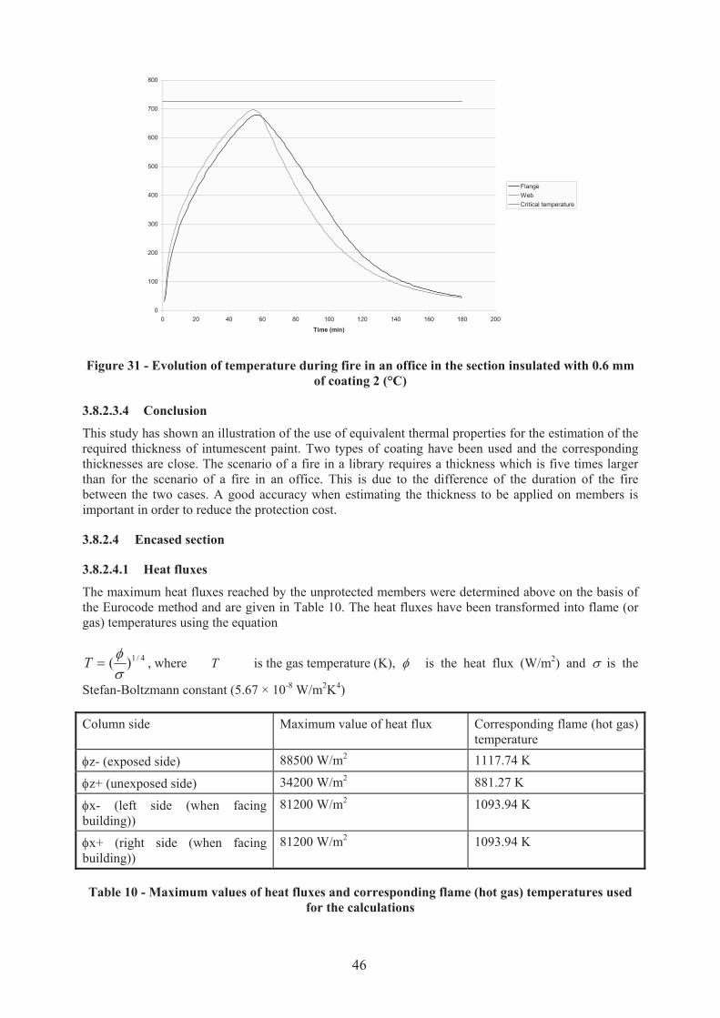
0
100
200
300
400
500
600
700
800
0 20 40 60 80 100 120 140 160 180 200
Time (min)
Flange
Web
Critical temperature
Figure 31 - Evolution of temperature during fire in an office in the section insulated with 0.6 mm
of coating 2 (°C)
3.8.2.3.4 Conclusion
This study has shown an illustration of the use of equivalent thermal properties for the estimation of the
required thickness of intumescent paint. Two types of coating have been used and the corresponding
thicknesses are close. The scenario of a fire in a library requires a thickness which is five times larger
than for the scenario of a fire in an office. This is due to the difference of the duration of the fire
between the two cases. A good accuracy when estimating the thickness to be applied on members is
important in order to reduce the protection cost.
3.8.2.4 Encased section
3.8.2.4.1 Heat fluxes
The maximum heat fluxes reached by the unprotected members were determined above on the basis of
the Eurocode method and are given in Table 10. The heat fluxes have been transformed into flame (or
gas) temperatures using the equation
4/1)(uh
?T , where T is the gas temperature (K), h is the heat flux (W/m2) and u is the
Stefan-Boltzmann constant (5.67 × 10⁻⁸ W/m2K4)
Column side Maximum value of heat flux Corresponding flame (hot gas)
temperature
hz- (exposed side) 88500 W/m2 1117.74 K
hz+ (unexposed side) 34200 W/m2 881.27 K
hx- (left side (when facing
building))
81200 W/m2 1093.94 K
hx+ (right side (when facing
building))
81200 W/m2 1093.94 K
Table 10 - Maximum values of heat fluxes and corresponding flame (hot gas) temperatures used
for the calculations
46
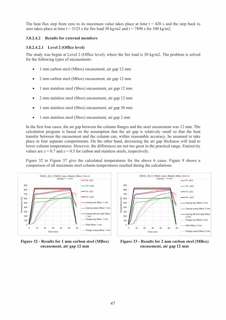
The heat flux step from zero to its maximum value takes place at time t = 420 s and the step back to
zero takes place at time t = 3125 s for fire load 30 kg/m2 and t = 7890 s for 100 kg/m2.
3.8.2.4.2 Results for external members
3.8.2.4.2.1 Level 2 (Office level)
The study was begun at Level 2 (Office level), where the fire load is 30 kg/m2. The problem is solved
for the following types of encasements:
‚ 1 mm carbon steel (Mbox) encasement, air gap 12 mm
‚ 2 mm carbon steel (Mbox) encasement, air gap 12 mm
‚ 1 mm stainless steel (Sbox) encasement, air gap 12 mm
‚ 2 mm stainless steel (Sbox) encasement, air gap 12 mm
‚ 1 mm stainless steel (Sbox) encasement, air gap 30 mm
‚ 1 mm stainless steel (Sbox) encasement, air gap 2 mm
In the first four cases, the air gap between the column flanges and the steel encasement was 12 mm. The
calculation program is based on the assumption that the air gap is relatively small so that the heat
transfer between the encasement and the column can, within reasonable accuracy, be assumed to take
place in four separate compartments. On the other hand, decreasing the air gap thickness will lead to
lower column temperatures. However, the differences are not too great in the practical range. Emissivity
values are g = 0.7 and g = 0.5 for carbon and stainless steels, respectively. "
Figure 32 to Figure 37 give the calculated temperatures for the above 6 cases. Figure 9 shows a
comparison of all maximum steel column temperatures reached during the calculations.
EXCOL_2D_H_TABLE_input_30kgm2_Mbox_1mm.m
Casing t = 1 mm
0
100
200
300
400
500
600
700
800
900
0 10 20 30 40 50 60
Time (min)
Tem
pera
ture
(oC
)
Tz- (oC)
Tz+ (oC)
Tx- (oC)
Tx+ (oC)
Casing exp Mbox 1 mm
Casing unexp Mbox 1 mm
Casing left and right Mbox
1 mm
Flange exp Mbox 1 mm
Web Mbox 1 mm
Flange unexp Mbox 1 mm
EXCOL_2D_H_TABLE_input_30kgm2_Mbox_2mm.m
Casing t = 2 mm
0
100
200
300
400
500
600
700
800
900
0 10 20 30 40 50 60
Time (min)
Tem
pera
ture
(oC
)
Tz- (oC)
Tz+ (oC)
Tx- (oC)
Tx+ (oC)
Casing exp Mbox 2 mm
Casing unexp Mbox 2 mm
Casing left and right Mbox
2 mm
Flange exp Mbox 2 mm
Web Mbox 2 mm
Flange unexp Mbox 2 mm
Figure 32 - Results for 1 mm carbon steel (MBox)
encasement, air gap 12 mm
Figure 33 - Results for 2 mm carbon steel (MBox)
encasement, air gap 12 mm
47

EXCOL_2D_H_TABLE_input_30kgm2_Sbox_1mm.m
Casing t = 1 mm
0
100
200
300
400
500
600
700
800
900
0 10 20 30 40 50 60
Time (min)
Tem
pera
ture
(oC
)
Tz- (oC)
Tz+ (oC)
Tx- (oC)
Tx+ (oC)
Casing exp Sbox 1 mm
Casing unexp Sbox 1 mm
Casing left and right Sbox
1 mm
Flange exp Sbox 1 mm
Web Sbox 1 mm
Flange unexp Sbox 1 mm
EXCOL_2D_H_TABLE_input_30kgm2_Sbox_2mm.m
Casing t = 2 mm
0
100
200
300
400
500
600
700
800
900
0 10 20 30 40 50 60
Time (min)
Tem
pera
ture
(oC
)
Tz- (oC)
Tz+ (oC)
Tx- (oC)
Tx+ (oC)
Casing exp Sbox 2 mm
Casing unexp Sbox 2 mm
Casing left and right Sbox
2 mm
Flange exp Sbox 2 mm
Web Sbox 2 mm
Flange unexp Sbox 2 mm
Figure 34 - Results for 1 mm stainless steel (SBox)
encasement, air gap 12 mm
Figure 35 - Results for 2 mm stainless steel (SBox)
encasement, air gap 12 mm
EXCOL_2D_H_TABLE_input_30kgm2_Sbox_1mm_gap30.m
Casing t = 1 mm
0
100
200
300
400
500
600
700
800
900
0 10 20 30 40 50 60
Time (min)
Tem
pera
ture
(oC
)
Tz- (oC)
Tz+ (oC)
Tx- (oC)
Tx+ (oC)
Casing exp Sbox 1 mm
Casing unexp Sbox 1 mm
Casing left and right Sbox
1 mm
Flange exp Sbox 1 mm
Web Sbox 1 mm
Flange unexp Sbox 1 mm
EXCOL_2D_H_TABLE_input_30kgm2_Sbox_1mm_gap2.m
Casing t = 1 mm
0
100
200
300
400
500
600
700
800
900
0 10 20 30 40 50 60
Time (min)
Tem
pera
ture
(oC
)
Tz- (oC)
Tz+ (oC)
Tx- (oC)
Tx+ (oC)
Casing exp Sbox 1 mm
Casing unexp Sbox 1 mm
Casing left and right Sbox 1
mm
Flange exp Sbox 1 mm
Web Sbox 1 mm
Flange unexp Sbox 1 mm
Figure 36 - Results for 1 mm stainless steel (SBox)
encasement, air gap 30 mm
Figure 37 - Results for 1 mm stainless steel (SBox)
encasement, air gap 2 mm
Level 2 (Office level): Comparison of maximum column temperatures
0
100
200
300
400
500
600
700
800
0 10 20 30 40 50 60
Time (min)
Tem
pera
ture
(oC
)
Mbox_1mm_gap12
Mbox_2mm_gap12
Sbox_1mm_gap12
Sbox_2mm_gap12
Sbox_1mm_gap30
Sbox_1mm_gap2
Figure 38 - Comparison of maximum column temperatures in different calculation cases
at Level 2
48
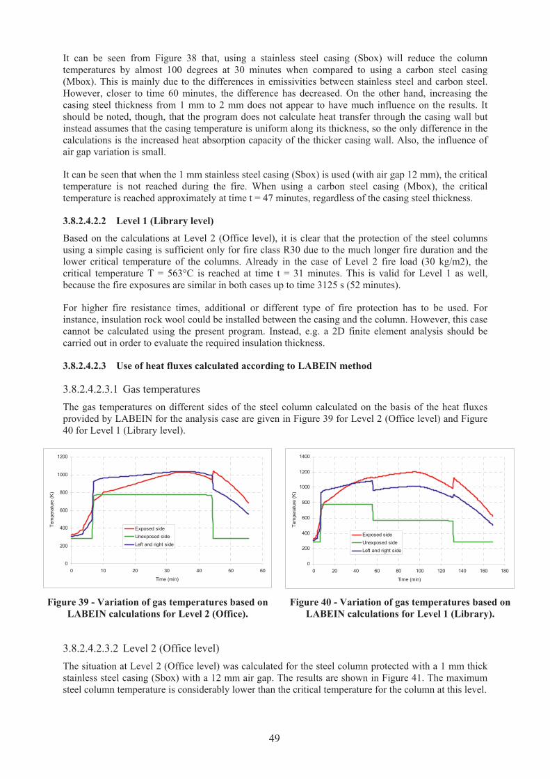
It can be seen from Figure 38 that, using a stainless steel casing (Sbox) will reduce the column
temperatures by almost 100 degrees at 30 minutes when compared to using a carbon steel casing
(Mbox). This is mainly due to the differences in emissivities between stainless steel and carbon steel.
However, closer to time 60 minutes, the difference has decreased. On the other hand, increasing the
casing steel thickness from 1 mm to 2 mm does not appear to have much influence on the results. It
should be noted, though, that the program does not calculate heat transfer through the casing wall but
instead assumes that the casing temperature is uniform along its thickness, so the only difference in the
calculations is the increased heat absorption capacity of the thicker casing wall. Also, the influence of
air gap variation is small.
It can be seen that when the 1 mm stainless steel casing (Sbox) is used (with air gap 12 mm), the critical
temperature is not reached during the fire. When using a carbon steel casing (Mbox), the critical
temperature is reached approximately at time t = 47 minutes, regardless of the casing steel thickness.
3.8.2.4.2.2 Level 1 (Library level)
Based on the calculations at Level 2 (Office level), it is clear that the protection of the steel columns
using a simple casing is sufficient only for fire class R30 due to the much longer fire duration and the
lower critical temperature of the columns. Already in the case of Level 2 fire load (30 kg/m2), the
critical temperature T = 563°C is reached at time t = 31 minutes. This is valid for Level 1 as well,
because the fire exposures are similar in both cases up to time 3125 s (52 minutes).
For higher fire resistance times, additional or different type of fire protection has to be used. For
instance, insulation rock wool could be installed between the casing and the column. However, this case
cannot be calculated using the present program. Instead, e.g. a 2D finite element analysis should be
carried out in order to evaluate the required insulation thickness.
3.8.2.4.2.3 Use of heat fluxes calculated according to LABEIN method
3.8.2.4.2.3.1 Gas temperatures
The gas temperatures on different sides of the steel column calculated on the basis of the heat fluxes
provided by LABEIN for the analysis case are given in Figure 39 for Level 2 (Office level) and Figure
40 for Level 1 (Library level).
0
200
400
600
800
1000
1200
0 10 20 30 40 50 60
Time (min)
Tem
pera
ture
(K
)
Exposed side
Unexposed side
Left and right side
0
200
400
600
800
1000
1200
1400
0 20 40 60 80 100 120 140 160 180
Time (min)
Tem
pera
ture
(K
)
Exposed side
Unexposed side
Left and right side
Figure 39 - Variation of gas temperatures based on
LABEIN calculations for Level 2 (Office).
Figure 40 - Variation of gas temperatures based on
LABEIN calculations for Level 1 (Library).
3.8.2.4.2.3.2 Level 2 (Office level)
The situation at Level 2 (Office level) was calculated for the steel column protected with a 1 mm thick
stainless steel casing (Sbox) with a 12 mm air gap. The results are shown in Figure 41. The maximum
steel column temperature is considerably lower than the critical temperature for the column at this level.
49
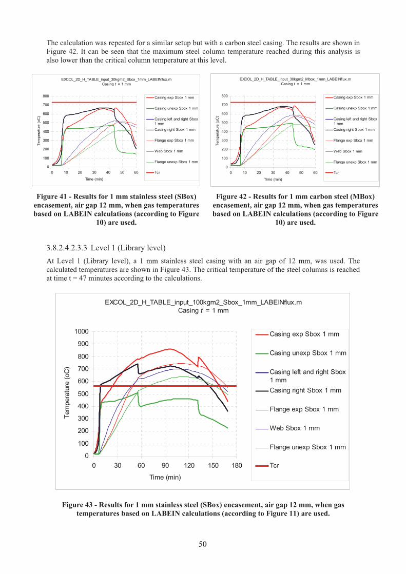
The calculation was repeated for a similar setup but with a carbon steel casing. The results are shown in
Figure 42. It can be seen that the maximum steel column temperature reached during this analysis is
also lower than the critical column temperature at this level.
EXCOL_2D_H_TABLE_input_30kgm2_Sbox_1mm_LABEINflux.m
Casing t = 1 mm
0
100
200
300
400
500
600
700
800
0 10 20 30 40 50 60
Time (min)
Tem
pera
ture
(oC
)
Casing exp Sbox 1 mm
Casing unexp Sbox 1 mm
Casing left and right Sbox
1 mm
Casing right Sbox 1 mm
Flange exp Sbox 1 mm
Web Sbox 1 mm
Flange unexp Sbox 1 mm
Tcr
EXCOL_2D_H_TABLE_input_30kgm2_Mbox_1mm_LABEINflux.m
Casing t = 1 mm
0
100
200
300
400
500
600
700
800
0 10 20 30 40 50 60
Time (min)
Tem
pera
ture
(oC
)
Casing exp Sbox 1 mm
Casing unexp Sbox 1 mm
Casing left and right Sbox
1 mm
Casing right Sbox 1 mm
Flange exp Sbox 1 mm
Web Sbox 1 mm
Flange unexp Sbox 1 mm
Tcr
Figure 41 - Results for 1 mm stainless steel (SBox)
encasement, air gap 12 mm, when gas temperatures
based on LABEIN calculations (according to Figure
10) are used.
Figure 42 - Results for 1 mm carbon steel (MBox)
encasement, air gap 12 mm, when gas temperatures
based on LABEIN calculations (according to Figure
10) are used.
3.8.2.4.2.3.3 Level 1 (Library level)
At Level 1 (Library level), a 1 mm stainless steel casing with an air gap of 12 mm, was used. The
calculated temperatures are shown in Figure 43. The critical temperature of the steel columns is reached
at time t = 47 minutes according to the calculations.
EXCOL_2D_H_TABLE_input_100kgm2_Sbox_1mm_LABEINflux.m
Casing t = 1 mm
0
100
200
300
400
500
600
700
800
900
1000
0 30 60 90 120 150 180
Time (min)
Tem
pera
ture
(oC
)
Casing exp Sbox 1 mm
Casing unexp Sbox 1 mm
Casing left and right Sbox
1 mm
Casing right Sbox 1 mm
Flange exp Sbox 1 mm
Web Sbox 1 mm
Flange unexp Sbox 1 mm
Tcr
Figure 43 - Results for 1 mm stainless steel (SBox) encasement, air gap 12 mm, when gas
temperatures based on LABEIN calculations (according to Figure 11) are used.
50
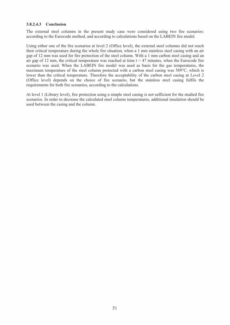
3.8.2.4.3 Conclusion
The external steel columns in the present study case were considered using two fire scenarios:
according to the Eurocode method, and according to calculations based on the LABEIN fire model.
Using either one of the fire scenarios at level 2 (Office level), the external steel columns did not reach
their critical temperature during the whole fire situation, when a 1 mm stainless steel casing with an air
gap of 12 mm was used for fire protection of the steel column. With a 1 mm carbon steel casing and an
air gap of 12 mm, the critical temperature was reached at time t = 47 minutes, when the Eurocode fire
scenario was used. When the LABEIN fire model was used as basis for the gas temperatures, the
maximum temperature of the steel column protected with a carbon steel casing was 589°C, which is
lower than the critical temperature. Therefore the acceptability of the carbon steel casing at Level 2
(Office level) depends on the choice of fire scenario, but the stainless steel casing fulfils the
requirements for both fire scenarios, according to the calculations.
At level 1 (Library level), fire protection using a simple steel casing is not sufficient for the studied fire
scenarios. In order to decrease the calculated steel column temperatures, additional insulation should be
used between the casing and the column.
51


4 CONCLUSIONS
The present report has been written after a research project of 42 months, by 5 European partners. It
was based on the real need within the building community for refurbishment of buildings, but also for
the design of new buildings. The project management has consisted on verifying the conformity with
the technical annex of the contract, and verifying that all conclusions were made in scientific and
consistent approach.
The present work has been based on numerical and experimental analysis performed within the project,
but also based on the existing experimental data. It has been also based on the knowledge used for the
development of the current eurocode model given in the annexes of the Eurocode 1 “actions in case of
fire” part 1.2 and Eurocode 3 part 1.2 “fire behaviour of steel structures”.
From all these works, development of methodologies has been made for:
‚ determination of thermal actions of external elements in case of fire inside the building as a
function of time
‚ thermal response of composite sections
‚ thermal response of steel structures protected by intumescent coatings
‚ thermal response of steel structure encased by the steel box
Three levels of complexity for determining the thermal actions as function of time should be used:
‚ a simplified analytical method
‚ a simplified analytical method using zone models results:
o for temperature-time curves inside the compartment
o for neutral axis within the compartment leading to the determination an equivalent
opening
‚ a global model based on CFD’s to deal with complex geometry or specific protection system
(as deflectors).
Many recommendations are given along the report. As a scientific and consistent approach, all the
results given have been verified with testing results comparison. The present work has then to be
valorised with publication and standardization documents (standards or guidelines).
53


5 EXPLOITATION AND IMPACT OF THE RESEARCH RESULTS
The introduction of the method of the verification of fire stability for unprotected steel sections within
the ENV1991-2-2 “actions in case of fire” and ENV1993-1-2 “fire behaviour of steel structures” had a
real impact for convincing fire brigade, and more generally fire authorities to use steel structures
outside a building without protection when the geometry of the building, the loading factors, the
localization of the structural elements allowed it.
Nevertheless, in many case, these parameters did not lead to a verification of the fire stability of the
structural elements. Few solutions existed to satisfy the fire stability, and no method, other than the
application of the standard ISO Fire was available.
So, on one hand, the requirements in terms of standard ISO Fire level applied to internal structures were
generally applied for the external elements. From this observation, solutions were limited and
expensive.
On the other hand, several building, as high rise building or at least building with several levels erected
before 80ies have used external steel structures without protected. Now, fire authorities asked to verify,
with current method of eurocode, their fire stability. When the results show that the structure and the
geometry of the built do not fulfil the fire stability, ISO Fire rating is required.
The development of a simplified transient method for determining the thermal actions to external
structural elements was thus necessary. The transient methodology developed within the present project
allows extending the current eurocode method for protected steel structures.
The present work allows to verify and clarify but also to modify when necessary the current eurocode
method as for example the effect of balconies.
Nevertheless, the determination of the thermal actions to external steel structures as a function of time
needs to calculate the thermal response of the structural elements. In fact, in term of ISO Fire rating
requirements, the level of protection of steel structures are given by graphs formulating the thickness of
protection as a function of the massivity factor of the section and ISO Fire rating. This approach could
not be applied for heat flux as a function of time. Moreover, lot of solution used for internal elements
are not possible for external elements, as for example sprays, rockwool or plasterboard encasement.
So methods to determine the thermal response of different solutions of protection or design of external
structural elements have been developed in the project.
Three main solutions are available for structural elements for which the fire stability is not verified by
the current eurocode model. These approaches can be used for refurbishment, but also may reduce the
cost of construction. These are for instance:
‚ composite columns, that contrary the ISO Fire Rating, can often be verified with rebars in, but
only filled of concrete
‚ Encasement solutions for beams and columns that generally can not fulfilled ISO Fire rating
higher than 30 minutes
‚ Intumescent coating for beams and columns with adapted thickness: solutions that are
appreciated in case of refurbishment keeping the initial architectural design
Also, the methodology allows different level of complexity: it gives some recommendations for the
third level using CFD’s. This third level may also be necessary for refurbishment or specific designs
when the 3 solutions given here above can not be used. For example, the use of simple steel deflector
protecting the unprotected steel sections needs to verify the conditions external flaming deviation by the
deflector.
55

For global view, the work performed within the research project will help the designers and the fire
engineers to find solutions for verifying the fire stability of the external steel or composite structure.
In order to valorise the present work, the methodology developed within the project should be introduce
in standardization, either in European standardization as next versions of Eurocodes, or in International
Standardization as ISO/TC92/SC4 Fire Safety Engineering.
In the future, articles will be published or presented in national, European or international conferences
for valorisation by the different partners.
56

6 LIST OF FIGURES AND TABLES
6.1 Figures
FIGURE 1 - OVERVIEW OF VTT TEST 1 .................................................................................................... 13
FIGURE 2 - FLAMES BURSTING OUT THE WINDOW DURING TEST 1 ......................................................... 14
FIGURE 3 - OVERVIEW OF EXPERIMENTAL TESTS (3 AND 4) PERFORMED BY CTICM ............................ 15
FIGURE 4 - CTICM TEST 1: ONE COLUMN LOCATED IN FRONT OF THE OPENING - FACADE VIEW.......... 16
FIGURE 5 - TNO EXPERIMENTAL SETUP .................................................................................................. 17
FIGURE 6 - OVERVIEW OF THE BENCHMARK CASE .................................................................................. 18
FIGURE 7 - MAIN STEPS IN THE GLOBAL MODEL ..................................................................................... 24
FIGURE 8 - EXAMPLE OF VALIDATION AGAINST EXPERIMENTAL MEASUREMENT .................................. 29
FIGURE 9 - STEPS TO VERIFY THE FIRE STABILITY OF STRUCTURAL ELEMENTS USING THE CURRENT
EUROCODE MODEL................................................................................................................................... 32
FIGURE 10 - STRATEGY RETAINED FOR THE SIMPLE MODEL ................................................................... 33
FIGURE 11 - EXAMPLE OF EXTERNAL COLUMNS PROTECTED BY DEFLECTORS....................................... 35
FIGURE 12 - PICTURE OF EXTERNAL MEMBERS ....................................................................................... 36
FIGURE 13 - LOCATION OF EXTERNAL MEMBERS .................................................................................... 36
FIGURE 14 - OVERVIEW OF THE REFERENCE COMPARTMENT.................................................................. 37
FIGURE 15 - HRR CURVES FOR THE TWO FIRE LOADS ............................................................................. 38
FIGURE 16 - HEAT FLUXES CURVE SHAPES FOR THE TWO FIRE LOAD ..................................................... 38
FIGURE 17 - TEMPERATURE OF THE COMPARTMENT FOR FIRE IN LEVEL 1.............................................. 39
FIGURE 18 - TEMPERATURE OF THE COMPARTMENT FOR FIRE IN LEVEL 2.............................................. 39
FIGURE 19 - TEMPERATURES WITHIN THE HEB 300 PROFILE IN FRONT OF THE OFFICE ......................... 40
FIGURE 20 - EVOLUTION OF TEMPERATURE IN THE BARE HEB 300 SECTION FOR FIRE IN THE LIBRARY 41
FIGURE 21 - COMPOSITE SECTION DESIGN PROPOSED FOR THE HEB 300 SECTION................................. 41
FIGURE 22 - COMPARISON OF TEMPERATURE EVOLUTION IN THE STEEL SECTION ................................. 41
FIGURE 23 - TEMPERATURE DISTRIBUTION WITHIN THE SECTION AT 110 MINUTES ............................... 42
FIGURE 24 - EXAMPLE OF TEMPERATURE FIELD IN THE SECTION DURING THE HEATING PHASE (°C)..... 43
FIGURE 25 - EXAMPLE OF TEMPERATURE FIELD IN THE SECTION DURING THE COOLING PHASE (°C) .... 43
FIGURE 26 - MAXIMUM TEMPERATURES REACHED WITHIN THE SECTION FOR COATING 1..................... 44
FIGURE 27 - MAXIMUM TEMPERATURES REACHED WITHIN THE SECTION FOR COATING 2..................... 44
FIGURE 28 - EVOLUTION OF TEMPERATURE DURING FIRE IN A LIBRARY IN THE SECTION INSULATED
WITH 2.5 MM OF COATING 1 (°C) ............................................................................................................. 44
FIGURE 29 - EVOLUTION OF TEMPERATURE DURING FIRE A LIBRARY IN THE SECTION INSULATED WITH
3.0 MM OF COATING 2 (°C) ...................................................................................................................... 45
FIGURE 30 - EVOLUTION OF TEMPERATURE DURING FIRE IN AN OFFICE IN THE SECTION INSULATED
WITH 0.6 MM OF COATING 1 (°C) ............................................................................................................. 45
FIGURE 31 - EVOLUTION OF TEMPERATURE DURING FIRE IN AN OFFICE IN THE SECTION INSULATED
WITH 0.6 MM OF COATING 2 (°C) ............................................................................................................. 46
57

FIGURE 32 - RESULTS FOR 1 MM CARBON STEEL (MBOX) ENCASEMENT, AIR GAP 12 MM ..................... 47
FIGURE 33 - RESULTS FOR 2 MM CARBON STEEL (MBOX) ENCASEMENT, AIR GAP 12 MM ..................... 47
FIGURE 34 - RESULTS FOR 1 MM STAINLESS STEEL (SBOX) ENCASEMENT, AIR GAP 12 MM ................... 48
FIGURE 35 - RESULTS FOR 2 MM STAINLESS STEEL (SBOX) ENCASEMENT, AIR GAP 12 MM ................... 48
FIGURE 36 - RESULTS FOR 1 MM STAINLESS STEEL (SBOX) ENCASEMENT, AIR GAP 30 MM ................... 48
FIGURE 37 - RESULTS FOR 1 MM STAINLESS STEEL (SBOX) ENCASEMENT, AIR GAP 2 MM ..................... 48
FIGURE 38 - COMPARISON OF MAXIMUM COLUMN TEMPERATURES IN DIFFERENT CALCULATION CASES
AT LEVEL 2 .............................................................................................................................................. 48
FIGURE 39 - VARIATION OF GAS TEMPERATURES BASED ON LABEIN CALCULATIONS FOR LEVEL 2
(OFFICE). ................................................................................................................................................. 49
FIGURE 40 - VARIATION OF GAS TEMPERATURES BASED ON LABEIN CALCULATIONS FOR LEVEL 1
(LIBRARY). .............................................................................................................................................. 49
FIGURE 41 - RESULTS FOR 1 MM STAINLESS STEEL (SBOX) ENCASEMENT, AIR GAP 12 MM, WHEN GAS
TEMPERATURES BASED ON LABEIN CALCULATIONS (ACCORDING TO FIGURE 10) ARE USED............... 50
FIGURE 42 - RESULTS FOR 1 MM CARBON STEEL (MBOX) ENCASEMENT, AIR GAP 12 MM, WHEN GAS
TEMPERATURES BASED ON LABEIN CALCULATIONS (ACCORDING TO FIGURE 10) ARE USED............... 50
FIGURE 43 - RESULTS FOR 1 MM STAINLESS STEEL (SBOX) ENCASEMENT, AIR GAP 12 MM, WHEN GAS
TEMPERATURES BASED ON LABEIN CALCULATIONS (ACCORDING TO FIGURE 11) ARE USED. ................50
6.2 Tables
TABLE 1 WORK PACKAGES AND CORRESPONDING TASKS ........................................................................ 7
TABLE 2 PROJECT MEETINGS..................................................................................................................... 9
TABLE 3 WORK SCHEDULE...................................................................................................................... 10
TABLE 4 DESCRIPTION OF TEST SPECIMEN TYPES ................................................................................... 12
TABLE 5 MAXIMUM TEMPERATURES REACHED FOR EACH SPECIMEN DURING THE TESTS ..................... 13
TABLE 6 CHARACTERISTICS OF THE TESTS.............................................................................................. 15
TABLE 7 MECHANICAL LOADS ................................................................................................................ 36
TABLE 8 CRITICAL TEMPERATURES FOR EXTERNAL MEMBERS .............................................................. 37
TABLE 9 HEAT FLUXES AND TEMPERATURES REACHED BY UNPROTECTED MEMBERS ACCORDING TO
EUROCODE METHOD (fZ- CORRESPONDS TO THE FACE FACING THE OPENING)...................................... 37
TABLE 10 MAXIMUM VALUES OF HEAT FLUXES AND CORRESPONDING FLAME (HOT GAS)
TEMPERATURES USED FOR THE CALCULATIONS ...................................................................................... 46
58
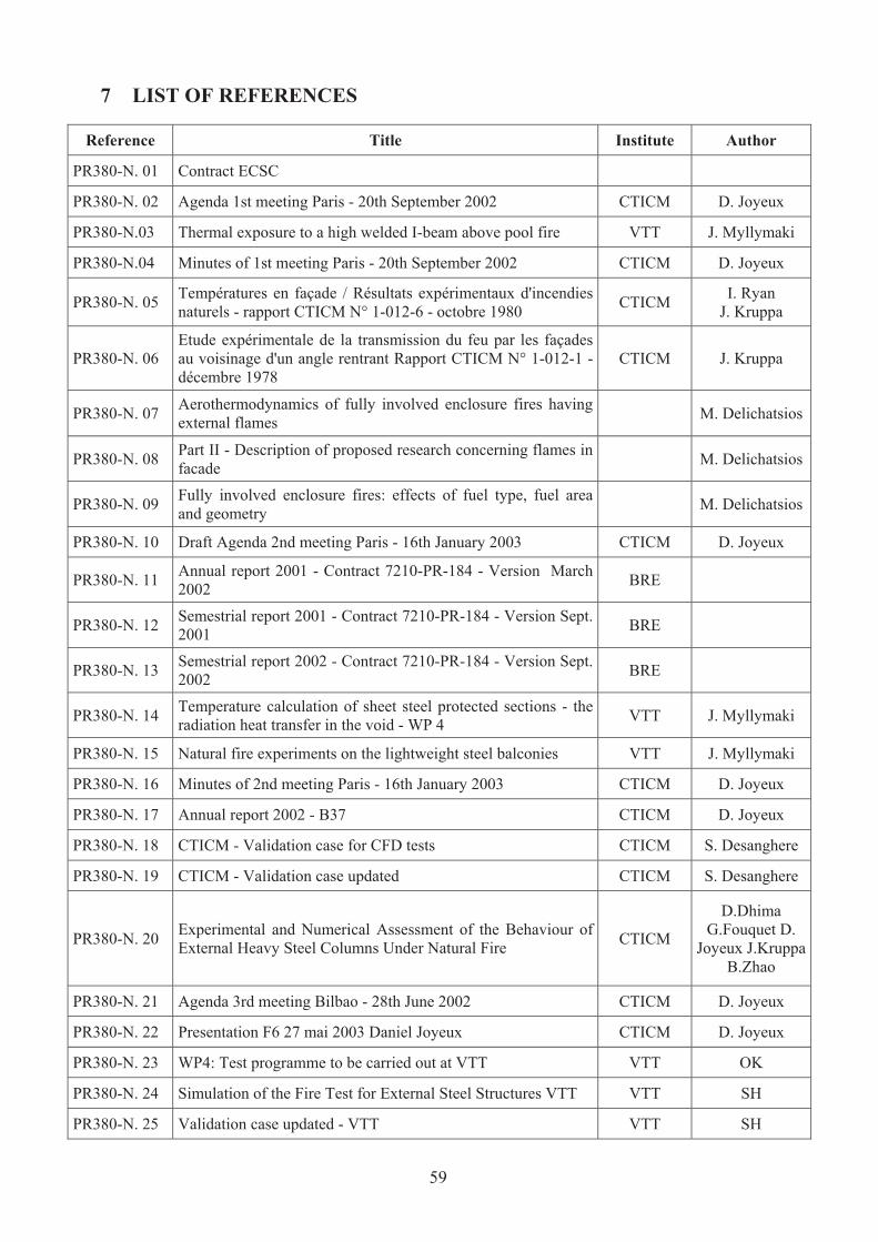
7 LIST OF REFERENCES
Reference Title Institute Author
PR380-N. 01 Contract ECSC
PR380-N. 02 Agenda 1st meeting Paris - 20th September 2002 CTICM D. Joyeux
PR380-N.03 Thermal exposure to a high welded I-beam above pool fire VTT J. Myllymaki
PR380-N.04 Minutes of 1st meeting Paris - 20th September 2002 CTICM D. Joyeux
PR380-N. 05 Températures en façade / Résultats expérimentaux d'incendies
naturels - rapport CTICM N° 1-012-6 - octobre 1980 CTICM
I. Ryan
J. Kruppa
PR380-N. 06
Etude expérimentale de la transmission du feu par les façades
au voisinage d'un angle rentrant Rapport CTICM N° 1-012-1 -
décembre 1978
CTICM J. Kruppa
PR380-N. 07 Aerothermodynamics of fully involved enclosure fires having
external flames M. Delichatsios
PR380-N. 08 Part II - Description of proposed research concerning flames in
facade M. Delichatsios
PR380-N. 09 Fully involved enclosure fires: effects of fuel type, fuel area
and geometry M. Delichatsios
PR380-N. 10 Draft Agenda 2nd meeting Paris - 16th January 2003 CTICM D. Joyeux
PR380-N. 11 Annual report 2001 - Contract 7210-PR-184 - Version March
2002 BRE
PR380-N. 12 Semestrial report 2001 - Contract 7210-PR-184 - Version Sept.
2001 BRE
PR380-N. 13 Semestrial report 2002 - Contract 7210-PR-184 - Version Sept.
2002 BRE
PR380-N. 14 Temperature calculation of sheet steel protected sections - the
radiation heat transfer in the void - WP 4 VTT J. Myllymaki
PR380-N. 15 Natural fire experiments on the lightweight steel balconies VTT J. Myllymaki
PR380-N. 16 Minutes of 2nd meeting Paris - 16th January 2003 CTICM D. Joyeux
PR380-N. 17 Annual report 2002 - B37 CTICM D. Joyeux
PR380-N. 18 CTICM - Validation case for CFD tests CTICM S. Desanghere
PR380-N. 19 CTICM - Validation case updated CTICM S. Desanghere
PR380-N. 20 Experimental and Numerical Assessment of the Behaviour of
External Heavy Steel Columns Under Natural Fire CTICM
D.Dhima
G.Fouquet D.
Joyeux J.Kruppa
B.Zhao
PR380-N. 21 Agenda 3rd meeting Bilbao - 28th June 2002 CTICM D. Joyeux
PR380-N. 22 Presentation F6 27 mai 2003 Daniel Joyeux CTICM D. Joyeux
PR380-N. 23 WP4: Test programme to be carried out at VTT VTT OK
PR380-N. 24 Simulation of the Fire Test for External Steel Structures VTT VTT SH
PR380-N. 25 Validation case updated - VTT VTT SH
59

PR380-N. 26 Minutes of 3rd meeting Bilbao - 18th June 2003 CTICM D. Joyeux
PR380-N. 27 ProfilArbed - Backgroung document on advanced fire models
according to 3.3.2 of prEN1991-1-2 (24-08-2001) ProfilArbed M. Haller
PR380-N. 28 LABEIN : Semestrial report September 2003 LABEIN J. Unanua
PR380-N. 29 ProfilArbed : PARE contribution to the semestrial report ProfilArbed M. Haller
PR380-N. 30 Semestrial report Period 01 January - 30 June 2003 CTICM D. Joyeux
PR380-N. 31 Progress report WP1 : Projection of external flames by
openings TNO T. Lemaire
PR380-N. 32 AGENDA : 4th meeting - 17th October 2003 CTICM D. Joyeux
PR380-N. 33 Fire Safety Journal : A comprehensive of externally venting
flames - Parts 1 and 2 LABEIN J. Unanua
PR380-N. 34 Fire-Safe Structural Steel - A design guide
American
Iron and
Steel
Institute
M. Law
PR380-N. 35
Engineering Fire Safety : Some selected papers by Margaret
Law - Published by ARUP
http://www.arup.com/fire/pdfs/papers1.htm
M. Law
PR380-N. 36 Minutes of the 4th meeting held on the 17th October in Delft CTICM S. Desanghere
PR380-N. 37 NIST-GCR-98-751 : Window breakage induced by exterior
fires (contract Nr COMMIP4024)
NIST
(National
Institute of
Standards
and
Technology)
F.W. Mowrer
PR380-N. 38 ACTIONS FOR THE BENCHMARK CTICM S. Desanghere
PR380-N. 39 AGENDA : 5th meeting - 12 February 2004 CTICM S. Desanghere
PR380-N. 40 Compte-rendu d'essai 76 R5 / T1 - Essai de réchauffement d'un
assemblage métallique protégé, soumis à un feu naturel CTICM D.Joyeux
PR380-N. 41 Compte-rendu d'essai 76 R6 / T2 - Essai de réchauffement d'un
assemblage métallique protégé et soumis à un feu naturel CTICM D.Joyeux
PR380-N. 42 Minutes of the fifth meeting held on 12 February 2004 in
Esch/Alzette CTICM D.Joyeux
PR380-N. 43 VTT Test report VTT O. Kaitila
PR380-N. 44 Second annual report - Contract 7210-PR-380 - Version March
2004 CTICM S. Desanghere
PR380-N. 45 Annual report Labein LABEIN J. Unanua
PR380-N. 46 Annual report ARBED ARBED M. Haller
PR380-N. 47 Annual report VTT VTT O. Kaitila
PR380-N. 48 Eurocode 1 Part 1.2 CEN
PR380-N. 49 Eurocode 3 Part 1.2 CEN
60
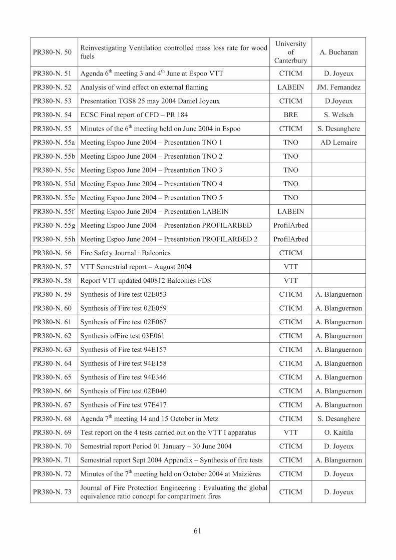
PR380-N. 50 Reinvestigating Ventilation controlled mass loss rate for wood
fuels
University
of
Canterbury
A. Buchanan
PR380-N. 51 Agenda 6th meeting 3 and 4th June at Espoo VTT CTICM D. Joyeux
PR380-N. 52 Analysis of wind effect on external flaming LABEIN JM. Fernandez
PR380-N. 53 Presentation TGS8 25 may 2004 Daniel Joyeux CTICM D.Joyeux
PR380-N. 54 ECSC Final report of CFD – PR 184 BRE S. Welsch
PR380-N. 55 Minutes of the 6th meeting held on June 2004 in Espoo CTICM S. Desanghere
PR380-N. 55a Meeting Espoo June 2004 – Presentation TNO 1 TNO AD Lemaire
PR380-N. 55b Meeting Espoo June 2004 – Presentation TNO 2 TNO
PR380-N. 55c Meeting Espoo June 2004 – Presentation TNO 3 TNO
PR380-N. 55d Meeting Espoo June 2004 – Presentation TNO 4 TNO
PR380-N. 55e Meeting Espoo June 2004 – Presentation TNO 5 TNO
PR380-N. 55f Meeting Espoo June 2004 – Presentation LABEIN LABEIN
PR380-N. 55g Meeting Espoo June 2004 – Presentation PROFILARBED ProfilArbed
PR380-N. 55h Meeting Espoo June 2004 – Presentation PROFILARBED 2 ProfilArbed
PR380-N. 56 Fire Safety Journal : Balconies CTICM
PR380-N. 57 VTT Semestrial report – August 2004 VTT
PR380-N. 58 Report VTT updated 040812 Balconies FDS VTT
PR380-N. 59 Synthesis of Fire test 02E053 CTICM A. Blanguernon
PR380-N. 60 Synthesis of Fire test 02E059 CTICM A. Blanguernon
PR380-N. 61 Synthesis of Fire test 02E067 CTICM A. Blanguernon
PR380-N. 62 Synthesis ofFire test 03E061 CTICM A. Blanguernon
PR380-N. 63 Synthesis of Fire test 94E157 CTICM A. Blanguernon
PR380-N. 64 Synthesis of Fire test 94E158 CTICM A. Blanguernon
PR380-N. 65 Synthesis of Fire test 94E346 CTICM A. Blanguernon
PR380-N. 66 Synthesis of Fire test 02E040 CTICM A. Blanguernon
PR380-N. 67 Synthesis of Fire test 97E417 CTICM A. Blanguernon
PR380-N. 68 Agenda 7th meeting 14 and 15 October in Metz CTICM S. Desanghere
PR380-N. 69 Test report on the 4 tests carried out on the VTT I apparatus VTT O. Kaitila
PR380-N. 70 Semestrial report Period 01 January – 30 June 2004 CTICM D. Joyeux
PR380-N. 71 Semestrial report Sept 2004 Appendix – Synthesis of fire tests CTICM A. Blanguernon
PR380-N. 72 Minutes of the 7th meeting held on October 2004 at Maizières CTICM D. Joyeux
PR380-N. 73 Journal of Fire Protection Engineering : Evaluating the global
equivalence ratio concept for compartment fires CTICM D. Joyeux
61

PR380-N. 74
Modification suggested for law model in EN 1991-1-2: 2002
Annex B: Influence of Balcony or awning above window on
flame temperatures
VTT O. Kaitila
PR380-N. 75 Agenda meeting 10-11 March in TNO CTICM D. Joyeux
PR380-N. 76
Report Simple Calculation Methods for the determination of
the temperature increase of steel sections protected with steel
casings
VTT O. Kaitila
PR380-N. 77 Annual report Period 01 January to 31 December 2004 CTICM D.Joyeux
PR380-N. 78 Minutes TGS8 May 2005 CTICM D.Joyeux
PR380-N. 79 USER’S MANUAL OF THE CODE EXTFIRE LABEIN F.Morente
PR380-N. 80 Minutes of the 8th meeting held on 10 and 11 March 2005 in
Delft CTICM D. Joyeux
PR380-N. 81 Simple calculation method for the determination of the
temperature increase of balcony slabs in fire conditions VTT
H. Biström, T.
Korhonen, O.
Kaitila
PR380-N. 82 Agenda – 8th Meeting Bilbao – 12 th and 13th October 2005 CTICM D. Joyeux
PR380-N. 83 Semestrial report (period : 01/01/2005 – 30/06/2005) CTICM D. Joyeux
PR380-N. 84
Proposal for methods to predict: Thermal actions on external
steel structures in the growing phase of a compartment fire,
version 2 (final) May 2004
TNO AD Lemaire
PR380-N. 85 Shadow: User guide and background, Version 1.1 (in progress)
Nov 2004 TNO AD Lemaire
PR380-N. 86
Study of the relation between the burning rate and heat flux in
compartment fires based on the law method. (final) March
2005
TNO I. Naus, AD
Lemaire
PR380-N. 87
A CFD study of non-uniform behaviour of external flaming
through multiple openings in compartment fires (final) March
2005
TNO YM Kenyon,
AD Lemaire
PR380-N. 88
Fire tests with external flaming on unprotected steel columns
including concrete filled columns (version 1.0) (in progress)
May 2005
TNO
A.D. Lemaire,
Y.M. Kenyon,
P. B. Reijman,
R. D. Scheepe
PR380-N. 89 Rapport d’essai 05K043 CTICM MZE
PR380-N. 90 Rapport d’essai 05K075 CTICM MZE
PR380-N. 91 Rapport d’essai 05K100 CTICM MZE
PR380-N. 92 The Global Equivalence Ratio Concept and the Prediction of
Carbon Monoxide Formation in Enclosure Fires
NIST
(National
Institute of
Standards
and
Technology)
WM Pitts
62

PR380-N. 93
The applicability of correlations between the species formation
and the global equivalence ratio in a 1/2 scaled ISO
compartment with nongaseous fuel
NIST
(National
Institute of
Standards
and
Technology)
C. Wieczorek,
U. Vandsburger,
C. McKay & S.
Sathyamoorthy
PR380-N. 94 Mintues of 8th Meeting Bilbao – 12 th and 13th October 2005 CTICM D. Joyeux
PR380-N. 95 USE OF SIMPLIFIED METHODS FOR EXTERNAL
MEMBERS: EXERCISE CTICM S. Desanghere
PR380-N. 96
HEAT TRANSFER MODEL ON EXTERNAL STEEL
ELEMENTS AND EXTERNAL HOLLOW SECTIONS
FILLED WITH CONCRETE
LABEIN J Unanua F
Morente
PR380-N. 97
VALIDATION OF THE HEAT TRANSFER MODEL ON
EXTERNAL STEEL ELEMENTS AND EXTERNAL
HOLLOW SECTIONS FILLED WITH CONCRETE
LABEIN J Unanua F
Morente
PR380-N. 98
CIDECT Research Project 15 Q April 1999 "Improvement and
extension of the simple calculation method for fire resistance
of unprotected oncrete filled hollow sections"
CTICM
C. Renaud
D. Joyeux
J. Kruppa
PR380-N. 99 Fire tests of protected steel columns heated by external flaming
with and without wind CTICM
D. Joyeux
S. Desanghere
PR380-N. 100 External steel structures research - Synthesis of fire test n° 92-
E-094 CTICM A. Blanguernon
PR380-N.
101
External steel structures research - Synthesis of fire test n° 92-
E-080 CTICM A. Blanguernon
PR380-N. 102 External steel structures research - Synthesis of fire test n° 92-
E-093 CTICM A. Blanguernon
PR380-N. 103
FIRE TESTS WITH EXTERNAL FLAMING ON
UNPROTECTED STEEL COLUMS INCLUDING
CONCRETE FILLED COLUMS
TNO
A.D. Lemaire
Y.M. Kenyon
P. B. Reijman
R. D. Scheepe
PR380-N. 104
Zur thermischen beanspruching von aussenstützen im
brandfall. Technical report, Technischen Universität
Braunschweig, 1977. HEFT 37
R. Bechtold
PR380-N. 105 Fire spread on exterior walls. Technical report, University of
Canterbury, 2000. ISSN 1173-5996 F. N. P. Bong
PR380-N. 106 Numerical simulations of fire exposed facades. Technical
report, Lund, 2001
J. Carlsson & B.
Carlsson
PR380-N. 107 Mass pyrolysis rates and excess pyrolysate in fully developed
enclosure fires. Fire Safety Journal, 39 : 1–21, 2004
M. Delichatsios,
G. Silcock, X.
Liu, M.
Delichatsios, &
Y. Lee
PR380-N. 108
Fully involved enclosure fires : Effects of fuel, type, fuel area
and geometry. IAFSS - Proceedings of the 7th International
Symposium, pages 59–74, 2002
M. A.
Delichatsios &
G. W. H.
Silcock
63
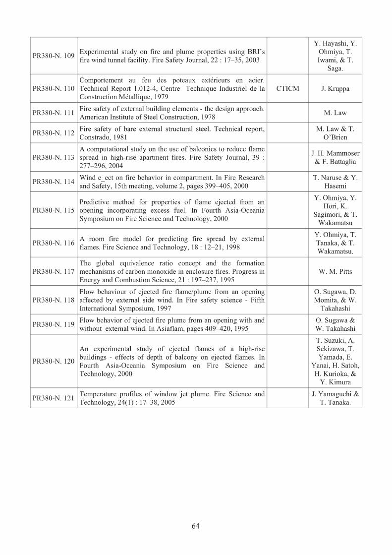
PR380-N. 109 Experimental study on fire and plume properties using BRI’s
fire wind tunnel facility. Fire Safety Journal, 22 : 17–35, 2003
Y. Hayashi, Y.
Ohmiya, T.
Iwami, & T.
Saga.
PR380-N. 110
Comportement au feu des poteaux extérieurs en acier.
Technical Report 1.012-4, Centre Technique Industriel de la
Construction Métallique, 1979
CTICM J. Kruppa
PR380-N. 111 Fire safety of external building elements - the design approach.
American Institute of Steel Construction, 1978 M. Law
PR380-N. 112 Fire safety of bare external structural steel. Technical report,
Constrado, 1981
M. Law & T.
O’Brien
PR380-N. 113
A computational study on the use of balconies to reduce flame
spread in high-rise apartment fires. Fire Safety Journal, 39 :
277–296, 2004
J. H. Mammoser
& F. Battaglia
PR380-N. 114 Wind e_ect on fire behavior in compartment. In Fire Research
and Safety, 15th meeting, volume 2, pages 399–405, 2000
T. Naruse & Y.
Hasemi
PR380-N. 115
Predictive method for properties of flame ejected from an
opening incorporating excess fuel. In Fourth Asia-Oceania
Symposium on Fire Science and Technology, 2000
Y. Ohmiya, Y.
Hori, K.
Sagimori, & T.
Wakamatsu
PR380-N. 116 A room fire model for predicting fire spread by external
flames. Fire Science and Technology, 18 : 12–21, 1998
Y. Ohmiya, T.
Tanaka, & T.
Wakamatsu.
PR380-N. 117
The global equivalence ratio concept and the formation
mechanisms of carbon monoxide in enclosure fires. Progress in
Energy and Combustion Science, 21 : 197–237, 1995
W. M. Pitts
PR380-N. 118
Flow behaviour of ejected fire flame/plume from an opening
affected by external side wind. In Fire safety science - Fifth
International Symposium, 1997
O. Sugawa, D.
Momita, & W.
Takahashi
PR380-N. 119 Flow behavior of ejected fire plume from an opening with and
without external wind. In Asiaflam, pages 409–420, 1995
O. Sugawa &
W. Takahashi
PR380-N. 120
An experimental study of ejected flames of a high-rise
buildings - effects of depth of balcony on ejected flames. In
Fourth Asia-Oceania Symposium on Fire Science and
Technology, 2000
T. Suzuki, A.
Sekizawa, T.
Yamada, E.
Yanai, H. Satoh,
H. Kurioka, &
Y. Kimura
PR380-N. 121 Temperature profiles of window jet plume. Fire Science and
Technology, 24(1) : 17–38, 2005
J. Yamaguchi &
T. Tanaka.
64
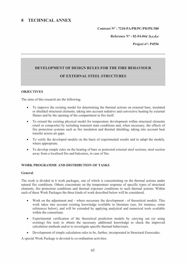
8 TECHNICAL ANNEX
Contract N° : 7210-PA/PB/PC/PD/PE/380
Reference N° : 02-F6.04a’,b,c,d,e
Project n°: P4556
DEVELOPMENT OF DESIGN RULES FOR THE FIRE BEHAVIOUR
OF EXTERNAL STEEL STRUCTURES
OBJECTIVES
The aims of this research are the following:
‚ To improve the existing model for determining the thermal actions on external bare, insulated
or shielded structural elements, taking into account radiative and convective heating by external
flames and by the opening of the compartment in fire itself.
‚ To extend the existing physical model for temperature development within structural elements
(steel or composite) by including transient state conditions and, when necessary, the effects of
fire protection systems such as fire insulation and thermal shielding, taking into account heat
transfer across air gaps.
‚ To verify the developed models on the basis of experimental results and to adapt the models,
where appropriate.
‚ To develop simple rules on the heating of bare or protected external steel sections, steel section
away from a localised fire and balconies, in case of fire.
WORK PROGRAMME AND DISTRIBUTION OF TASKS
General
The work is divided in 6 work packages, one of which is concentrating on the thermal actions under
natural fire conditions. Others concentrate on the temperature response of specific types of structural
elements, fire protection conditions and thermal exposure conditions to such thermal actions. Within
each of these Work Packages the three kinds of work described below will be considered.
‚ Work on the adjustment and – where necessary the development - of theoretical models. This
work takes into account existing knowledge available in literature (see, for instance, some
references below), and will be extended by applying analytical and numerical tools available
within the consortium.
‚ Experimental verification of the theoretical prediction models by carrying out (or using
existing) fire tests to obtain the necessary additional knowledge to check the improved
calculation methods and/or to investigate specific thermal behaviours.
‚ Development of simple calculation rules to be, further, incorporated in Structural Eurocodes.
A special Work Package is devoted to co-ordination activities.
65

Work content
The 6 work packages (WP) are covering the various areas needed in the whole development work and
management. The detailed contents of work packages (including estimated costs) are presented in the
following tables.
66

WP 1 - Projection of external flames by openings
Responsible partner: TNO Other partners: CTICM, LABEIN, VTT
Objectives: Development of methods to predict the heat flux to structural elements from external
plumes
Description:
The tasks are:
Introduction of literature data on external and façade fires gathered since the development of the present
model by M. Law in the seventies. Emphasis is on :
- Application of recent developments in natural compartment fire analysis to predict the source of
thermal radiation by openings.
- Development of a numerical “scanning technique” to predict radiative heat flux to structural
elements more accurately than in the present models.
- Application of Computational Fluid Dynamics modelling techniques to predict geometry,
temperature and composition of flames projecting from openings, with or without balconies and to
predict convective and radiative heat transfer to structural elements within or adjacent to the flames.
The theoretical model will be verified by carrying out a limited number of well-conditioned experiments
in conjunction with similar work within the other work packages. These experiments will provide also
data on steel sections, unprotected and protected by shielding.
The work will be completed by sensitivity analysis to ensure reliability of the models on the given
ranges and the development of simple calculation rules for thermal exposure and heat transfer
characteristics on structural elements for inclusion in the Structural Eurocodes.
Activity:
Theoretical work
Experimental testing
67

WP 2 - Heating up of steel or composite bare sections
Responsible partner: LABEIN Other partners: ARBED, CTICM, TNO
Objectives: Development of temperature calculation methods for composite external elements
Description:
For bare steel the existing simplified model to calculate the steel temperature described in ENV
1993-1-2 will be updated to take into account transient radiative and convective heat flux produced
by external flame or by localised fires. The view factor governing the radiative heat exchange will
be investigated in details because its influence is relevant in the heating of external elements made
with mild or stainless steel.
For composite sections, numerous numerical analyses calculating the temperature field in composite
elements, when exposed to natural fires, will be performed in order to deduce simplified models to
be incorporated in Structural Eurocodes.
Results of tests performed within other work packages will be taken into consideration for checking
the accuracy of the simplified calculation methods developed.
Activity:
Theoretical work
68

WP 3 - Heating up of protected steel sections
Responsible partner: CTICM Other partners: ARBED, VTT
Objectives: Development of temperature calculation methods for protected external elements
Description:
Based on the improved calculation methods developed within WP 2, further developments will be
performed in order to cover the case of sections insulated by protection materials as intumescent
paints. Additionally, a proposal will be made to obtain the necessary thermal characteristics of
protection materials to be used under natural fire conditions. The following steps will be carried out :
- assessment by numerical simulations of the heating up of external steel section insulated by a
protection material;
- experiments, on a limited number of cases, under natural fire conditions, to obtain the necessary
data to check the accuracy of the numerical simulations for insulated steel and composite external
elements, as well as to provide data for WP1 (temperatures for external flames) and WP 2
(temperatures of bare steel and composite elements);
Activity:
Theoretical work
Experimental testing
69
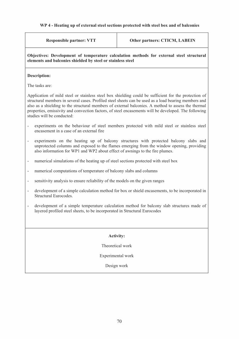
WP 4 - Heating up of external steel sections protected with steel box and of balconies
Responsible partner: VTT Other partners: CTICM, LABEIN
Objectives: Development of temperature calculation methods for external steel structural
elements and balconies shielded by steel or stainless steel
Description:
The tasks are:
Application of mild steel or stainless steel box shielding could be sufficient for the protection of
structural members in several cases. Profiled steel sheets can be used as a load bearing members and
also as a shielding to the structural members of external balconies. A method to assess the thermal
properties, emissivity and convection factors, of steel encasements will be developed. The following
studies will be conducted:
- experiments on the behaviour of steel members protected with mild steel or stainless steel
encasement in a case of an external fire
- experiments on the heating up of balcony structures with protected balcony slabs and
unprotected columns and exposed to the flames emerging from the window opening, providing
also information for WP1 and WP2 about effect of awnings to the fire plumes.
- numerical simulations of the heating up of steel sections protected with steel box
- numerical computations of temperature of balcony slabs and columns
- sensitivity analysis to ensure reliability of the models on the given ranges
- development of a simple calculation method for box or shield encasements, to be incorporated in
Structural Eurocodes.
- development of a simple temperature calculation method for balcony slab structures made of
layered profiled steel sheets, to be incorporated in Structural Eurocodes
Activity:
Theoretical work
Experimental work
Design work
70

WP 5 - Heating up of sections by localised fires
Responsible partner: ProfilARBED Other partners: TNO
Objectives: Development of temperature calculation methods for internal steel structural
elements exposed localised fires
Description:
The tasks are:
Based on fire engineering methodology, simple tools will be developed to determine the temperature
of an unprotected steel section submitted to unconfined (localised) fires, with no accumulation of
smoke. The work on the view factor, governing the radiative heat exchange, to be made within WP 2,
will be taken into consideration within this WP 5.
The following studies will be conducted:
- research of experimental data on the temperature of steel members located in the vicinity of
localised fires
- numerical simulations of the heating up of these steel sections
- sensitivity analysis to ensure reliability of the model on the given ranges
- development of a simple temperature calculation method for these elements, to be incorporated in
Structural Eurocodes
Activity:
Theoretical work
Design work
71

WP 6 - Project coordination.
Responsible partner: CTICM Other partners: Coordinators of sub-work
packages
Objectives:
CTICM will be responsible for the overall management of the project. It will be responsible
for preparing a detailed project plan indicating the key dates. It will organise 2 or 3 meetings a
year among the partners and co-ordinate the semestrial and annual reports to the
Commission.
Description:
This work package covers all management and co-ordination activities required to keep the project
on schedule and to cost. This includes:
- Planning of work packages and their inter-relationships;
- Liaison with partners and sub-contractors to monitor progress and identify difficulties;
- Adoption of measures to rectify any problems;
- Progress reporting;
- Organization and running of progress meetings;
- Liaison with ECSC;
- Project administration
Activity
Project management
Final report
72
