technique and safety of performing eeg/fmri … and safety of performing eeg/fmri measurements ......
TRANSCRIPT

Technique and Safety of performing EEG/fMRI measurementsperforming EEG/fMRI measurements
by Pierluigi Castellone, Electronics Engineer
Brain Products‘ General Manager
Contents of the presentation
� Why recording simultaneous EEG and fMRI?
� Challenges in recording EEG in the MRI: Safety issues
� Challenges in recording EEG in the MRI: Technical issues� Challenges in recording EEG in the MRI: Technical issues
� Brain Products solutions and recommendations
� Four steps to successful EEG/fMRI measurement
Reading (UK), July 7th to 8th, 2010 Workshop on EEG & TMS and EEG & fMRI
Why recording EEG?
� The activation of neurons produces an electrical signal which can be
detected by using electrodes placed on the scalp.
� Being an electrical signal, any change in the neural activation is
detected very quickly. The EEG has time resolution in the order of
milliseconds but bad spatial resolution (inverse problem not solvable).
Reading (UK), July 7th to 8th, 2010 Workshop on EEG & TMS and EEG & fMRI
Why recording fMRI?
� Stimulation of the brain causes a local increase in blood flow. To the
increase of oxygen in the activated areas does not correspond an
increase of the used oxygen. This results in a net increase of oxygen in
the area activated.
� We can recognize two phases related to the brain activation:
(1) Deoxygenated blood (Paramagnetic – distortions in the MRI signal)
increases due to areas activated. T2 and T1 are shorter.
(2) Oxygenated blood (Diamagnetic – no distortions in the MRI signal)
flows in the activated areas. T2 and T1 are longer.
� By scanning the brain over time repeatedly, it’s possible to detect the
BOLD (Blood Oxygenation Level Dependent) signal.
Reading (UK), July 7th to 8th, 2010 Workshop on EEG & TMS and EEG & fMRI
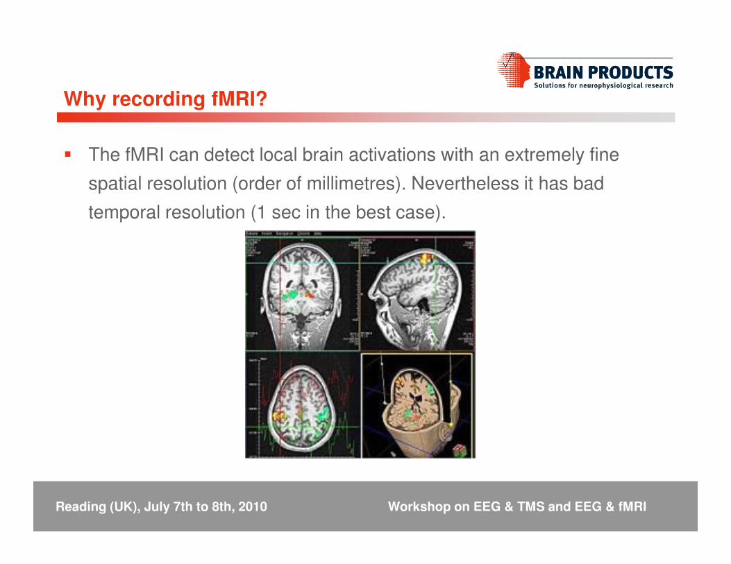
Why recording fMRI?
� The fMRI can detect local brain activations with an extremely fine
spatial resolution (order of millimetres). Nevertheless it has bad
temporal resolution (1 sec in the best case).
Reading (UK), July 7th to 8th, 2010 Workshop on EEG & TMS and EEG & fMRI
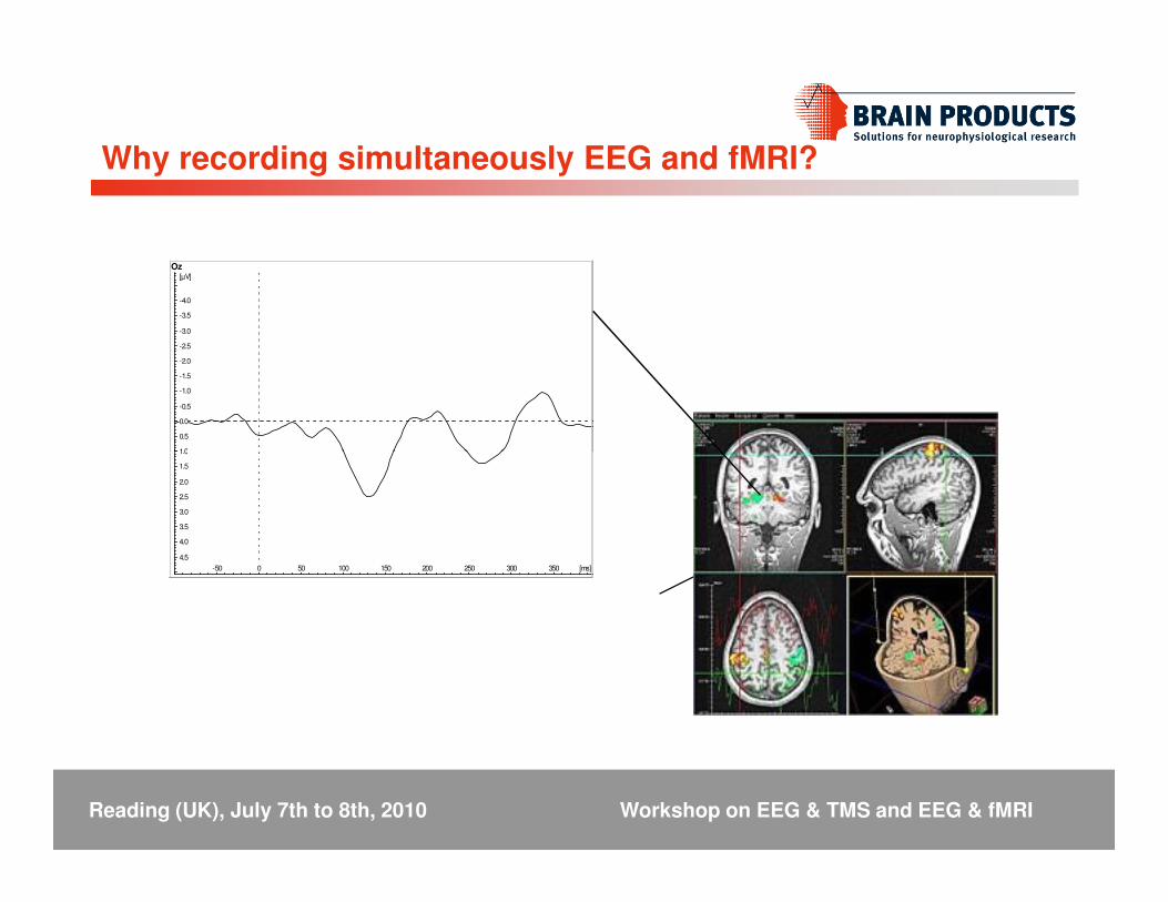
Why recording simultaneously EEG and fMRI?
1.0
0.5
0.0
-0.5
-1.0
-1.5
-2.0
-2.5
-3.0
-3.5
-4.0
[µV]
Oz
4.5
4.0
3.5
3.0
2.5
2.0
1.5
1.0
-50 0 50 100 150 200 250 300 350 [ms]
Reading (UK), July 7th to 8th, 2010 Workshop on EEG & TMS and EEG & fMRI
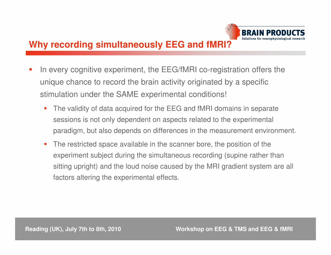
Why recording simultaneously EEG and fMRI?
� In every cognitive experiment, the EEG/fMRI co-registration offers the
unique chance to record the brain activity originated by a specific
stimulation under the SAME experimental conditions!
� The validity of data acquired for the EEG and fMRI domains in separate
sessions is not only dependent on aspects related to the experimental
paradigm, but also depends on differences in the measurement environment. paradigm, but also depends on differences in the measurement environment.
� The restricted space available in the scanner bore, the position of the
experiment subject during the simultaneous recording (supine rather than
sitting upright) and the loud noise caused by the MRI gradient system are all
factors altering the experimental effects.
Reading (UK), July 7th to 8th, 2010 Workshop on EEG & TMS and EEG & fMRI

Why recording simultaneous EEG and fMRI?
� In every cognitive experiment, the EEG/fMRI co-registration offers the
unique chance to record the brain activity originated by a specific
stimulation under the SAME experimental conditions!
� To reduce the costs related to the experiments� To reduce the costs related to the experiments
� To reduce the working time
Reading (UK), July 7th to 8th, 2010 Workshop on EEG & TMS and EEG & fMRI
Challenges in recording EEG in the fMRI: Safety IssuesEEG in the fMRI: Safety Issues

The MRI scanner
Reading (UK), July 7th to 8th, 2010 Workshop on EEG & TMS and EEG & fMRI

The MRI scanner
Reading (UK), July 7th to 8th, 2010 Workshop on EEG & TMS and EEG & fMRI
EPI sequence design

Challenges in recording EEG in the MRI: Safety issues
(1) Static magnetic field
(2) Gradients
(3) Radio frequency pulses
The strength of the magnetic field of a scanner is measured in units of
Reading (UK), July 7th to 8th, 2010 Workshop on EEG & TMS and EEG & fMRI
The strength of the magnetic field of a scanner is measured in units of
“Tesla”. Today, a normal magnet would be a 1.5 or 3T scanner, where 3T
means that the magnetic field is roughly 60.000x stronger than the earth’s
natural magnetic field of .00005T!
This static magnetic field is ALWAYS on!

It is normally not possible to
remove such an object since
simple human power and force is
insufficient for removal.
Challenges in recording EEG in the MRI: Safety issues
Complete patient monitoring system wedged in the opening of a 1.5 T MR scanner system
In most of the cases the scanner
has to be “quenched”, completely
shutting off the power and the
Helium cooling system.
The cost of this is approximately
250.000 $!
Reading (UK), July 7th to 8th, 2010 Workshop on EEG & TMS and EEG & fMRI

Challenges in recording EEG in the MRI: Safety issues
� Acoustic noise:
During MR imaging, the slowly-varying gradient fields
are continuously turned on and off at variable rates and cause a loud
noise (mechanical resonance) .
Ear plugs and passive noise reduction are needed.
Reading (UK), July 7th to 8th, 2010 Workshop on EEG & TMS and EEG & fMRI
� Neural activation:
The gradients being switched are so strong that they can lead to
peripheral nerve stimulation and peripheral muscle contraction.
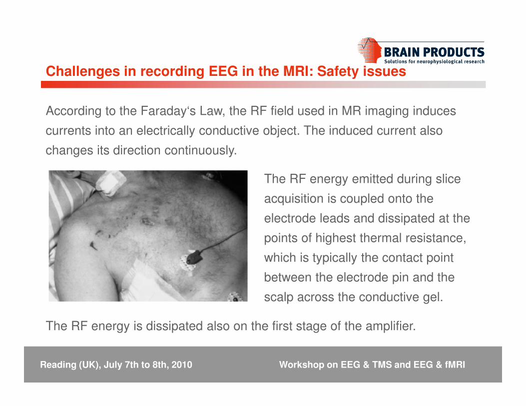
According to the Faraday‘s Law, the RF field used in MR imaging induces
currents into an electrically conductive object. The induced current also
changes its direction continuously.
Challenges in recording EEG in the MRI: Safety issues
The RF energy emitted during slice
acquisition is coupled onto the acquisition is coupled onto the
electrode leads and dissipated at the
points of highest thermal resistance,
which is typically the contact point
between the electrode pin and the
scalp across the conductive gel.
Reading (UK), July 7th to 8th, 2010 Workshop on EEG & TMS and EEG & fMRI
The RF energy is dissipated also on the first stage of the amplifier.

Challenges in recording EEG in the MRI: Safety issues
Reading (UK), July 7th to 8th, 2010 Workshop on EEG & TMS and EEG & fMRI
Brain Products solutions and recommendations
BrainAmp MR systems are the only commercially available solutions
designed to work directly INSIDE the MRI bore:
� There is no ferrite in the amplifier
� The system is powered by MRI-compatible batteries
� The first stage of the amplifier filters out high frequencies potentially � The first stage of the amplifier filters out high frequencies potentially
very dangerous for the hardware
� Most of the more sensitive electronics circuitry needed to operate the
system are in the control room (USB interface)
Reading (UK), July 7th to 8th, 2010 Workshop on EEG & TMS and EEG & fMRI
Brain Products solutions and recommendations
� The electrical connections from the cap to the amplifier’s input stage are
shorter and thereby the influence of the MRI gradient switching system
on the acquired data is minimized.
� Furthermore, shorter cables massively reduce the likelihood to spoil the
data acquisition with artifacts induced by cable motion and other types
Reading (UK), July 7th to 8th, 2010 Workshop on EEG & TMS and EEG & fMRI
of noise in the MRI environment.
Brain Products solutions and recommendations
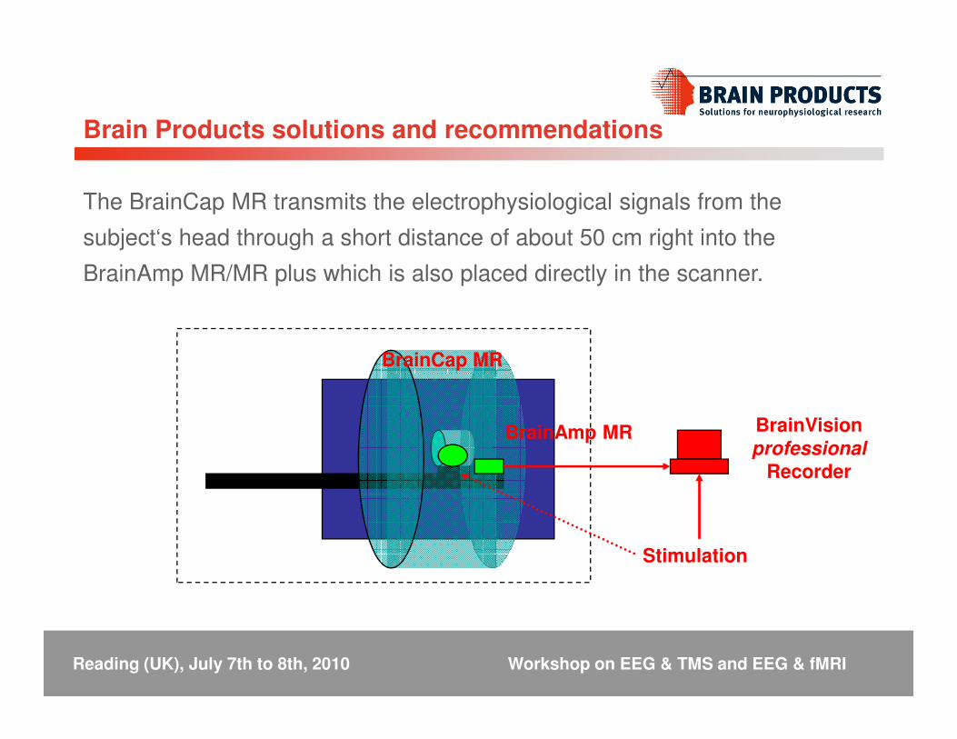
The BrainCap MR transmits the electrophysiological signals from the
subject‘s head through a short distance of about 50 cm right into the
BrainAmp MR/MR plus which is also placed directly in the scanner.
BrainCap MRBrainCap MR
BrainAmp MR BrainVisionprofessional
Recorder
Stimulation
Reading (UK), July 7th to 8th, 2010 Workshop on EEG & TMS and EEG & fMRI

Brain Products solutions and recommendations
BrainCap MR features (1):
� In the combined EEG/fMRI acquisition the electrodes should never touch the skin.
Our electrodes are pin type sensors which are placed inside a plastic holder
mounted on the cap. Gel will be filled into the holder to reduce skin conductance
and to establish a contact between the sensor and the subject's skin.
� Every electrode contains safety resistors between the sensor and the connection � Every electrode contains safety resistors between the sensor and the connection
wire. Connection between the components is performed by gluing, not soldering.
� Additional safety resistors are placed inside the cap connector, acting like an
additional RF-filter.
� Wires are located at the outside of the cap to ensure isolation between skin and
wire according to the FDA patient safety regulations.
Reading (UK), July 7th to 8th, 2010 Workshop on EEG & TMS and EEG & fMRI

Brain Products solutions and recommendations
BrainCap MR features (2):
� High temperature isolating tubes wrapped around the ECG electrode cable avoid
creating contact between skin and wire.
� Drop-down electrodes contain higher resistors than normal electrodes to
compensate the technical characteristics of longer wires.
� All wires are fixed onto the cap to avoid loops.
� Wire length from electrode to the amplifier’s input is fixed to a maximum of 1.5m
not to match the Larmor frequency.
� Wire outlets for the cable tree at central positions avoid creating loops due to
cable routing.
Reading (UK), July 7th to 8th, 2010 Workshop on EEG & TMS and EEG & fMRI
Brain Products solutions and recommendations
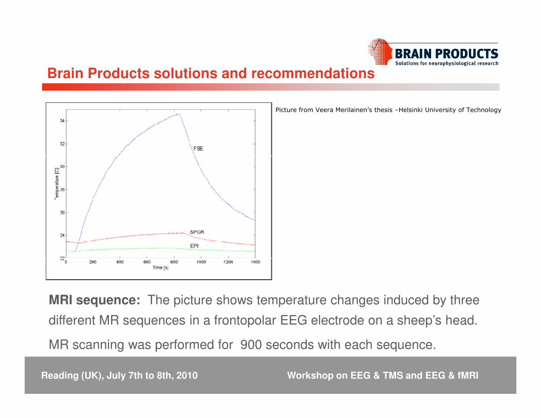
Picture from Veera Merilainen’s thesis –Helsinki University of Technology
MRI sequence: The picture shows temperature changes induced by three
different MR sequences in a frontopolar EEG electrode on a sheep’s head.
MR scanning was performed for 900 seconds with each sequence.
Reading (UK), July 7th to 8th, 2010 Workshop on EEG & TMS and EEG & fMRI

Brain Products solutions and recommendations
� Strict restriction to low SAR sequences
� GE-Localizer
� GE-Structural sequences (MP-RAGE)
� GE-EPI
� Whenever the subject wears a EEG cap:� Whenever the subject wears a EEG cap:
� No Spin-Echo
� No Turbo-Spin-Echo
� No Spiral-EPI
� Avoid Body-Coil Tx !!
� Use whenever available head coil TxRx
Reading (UK), July 7th to 8th, 2010 Workshop on EEG & TMS and EEG & fMRI

What not to do…
Reading (UK), July 7th to 8th, 2010 Workshop on EEG & TMS and EEG & fMRI

Otherwise…
Reading (UK), July 7th to 8th, 2010 Workshop on EEG & TMS and EEG & fMRI

Challenges in recording EEG in the fMRI: Technical IssuesEEG in the fMRI: Technical Issues

Challenges in recording EEG in the MRI: Technical issues
� When an object with the susceptibility* different from that of surrounding
tissues is placed in a homogeneous magnetic field, it distorts the field
and causes local inhomogeneties.
*In physics and electrical engineering, the magnetic susceptibility is the degree of magnetization
of a material
Reading (UK), July 7th to 8th, 2010 Workshop on EEG & TMS and EEG & fMRI

� Two clear artifacts are visible in the EEG during the combined
experiment:
(1) Gradient artifact
(2) Pulse artifact
Challenges in recording EEG in the MRI: Technical issues
Reading (UK), July 7th to 8th, 2010 Workshop on EEG & TMS and EEG & fMRI
Fp1Fp2F3F4C3C4P3P4O1
Challenges in recording EEG in the MRI: Technical issues
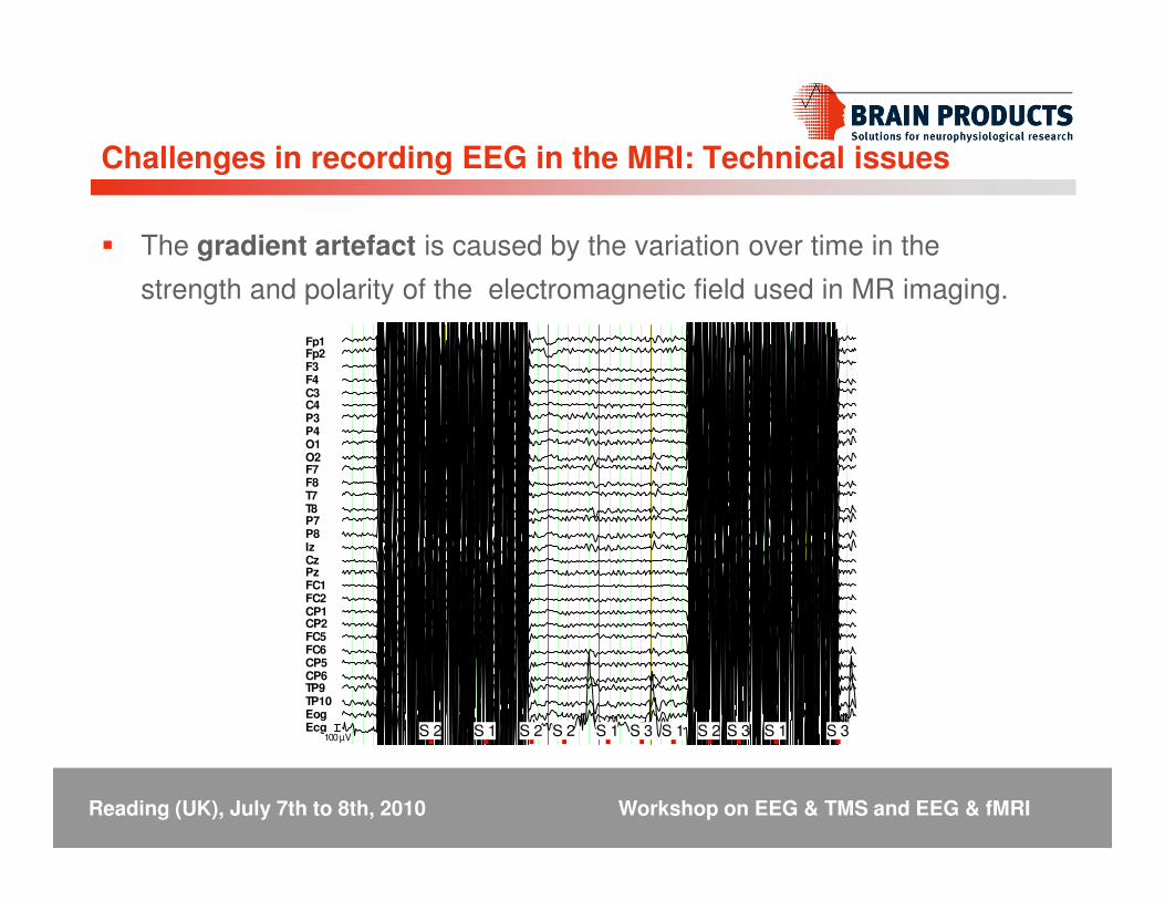
� The gradient artefact is caused by the variation over time in the
strength and polarity of the electromagnetic field used in MR imaging.
O1O2F7F8T7T8P7P8IzCzPzFC1FC2CP1CP2FC5FC6CP5CP6TP9TP10EogEcg S 2 S 1 S 2 S 2 S 1 S 3 S 1 S 2 S 3 S 1 S 3100 µV
Reading (UK), July 7th to 8th, 2010 Workshop on EEG & TMS and EEG & fMRI
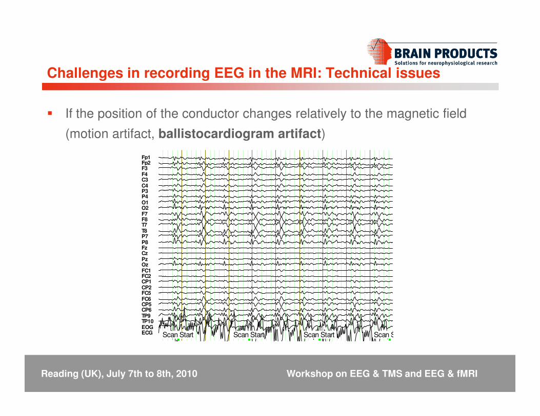
� If the position of the conductor changes relatively to the magnetic field
(motion artifact, ballistocardiogram artifact)
Fp1Fp2F3F4C3C4P3P4O1O2
Challenges in recording EEG in the MRI: Technical issues
O2F7F8T7T8P7P8FzCzPzOzFC1FC2CP1CP2FC5FC6CP5CP6TP9TP10EOGECG Scan Start Scan Start Scan Start Scan Start
Reading (UK), July 7th to 8th, 2010 Workshop on EEG & TMS and EEG & fMRI
Challenges in recording EEG in the MRI: Technical issues
Four steps to successful EEG/fMRI measurement …
(1) Safe Subject Preparation
(2) Trigger Setup / Synchronization
(3) Proper Measurement Settings
(4) Correct Data Preparation(4) Correct Data Preparation
Reading (UK), July 7th to 8th, 2010 Workshop on EEG & TMS and EEG & fMRI

Challenges in recording EEG in the MRI: Technical issues
(1) Safe subject preparation
� Informed consent must be obtained from all subjects!
� It must be established that the subject does not have any implants that are
ferrous or magnetizable.
� The subject must be free from claustrophobia.
� The subject has to fully understand the procedure and also any potential
causes of harm such as the ambient noise, gradient induced peripheral
effects and the difficulty of fast exiting.
Reading (UK), July 7th to 8th, 2010 Workshop on EEG & TMS and EEG & fMRI

Challenges in recording EEG in the MRI: Technical issues
(2) Trigger Setup
� Scanner artifacts are technical in nature, meaning that they are always the
same from acquisition to acquisition. In order to correct the EEG data for
these artifacts we must find the onset of each of these episodes very exactly.
� This can either be done in software by detecting features or values or it can
be done with the help of the scanner system, which can normally issue a
Reading (UK), July 7th to 8th, 2010 Workshop on EEG & TMS and EEG & fMRI
be done with the help of the scanner system, which can normally issue a
trigger at the exact time point of slice or volume acquisition.
� On BrainAmp MR systems, the normal stimulation system trigger cable is
complemented with a BNC trigger input that is internally connected to Bit 15,
thus giving a trigger of type “Response” and with the code “R128” for every
pulse the scanner sends.
� Most scanners are set up to send such a pulse with every slice or with every
volume onset by default.
Challenges in recording EEG in the MRI: Technical issues
(2) Synchronization
� Most scanners provide the service technicians with a diagnostic output that is
phase synchronous with the gradient clock itself.
� This mechanism allows for easy synchronization between the scanner
gradient system and the BrainAmp sample clock.
Reading (UK), July 7th to 8th, 2010 Workshop on EEG & TMS and EEG & fMRI
� The scanner has to provide a signal that is an integer multiple of 5000 Hz,
such as 20 kHz, 1 MHz, 20 MHz, …

Challenges in recording EEG in the MRI: Technical issues
Reading (UK), July 7th to 8th, 2010 Workshop on EEG & TMS and EEG & fMRI

Challenges in recording EEG in the MRI: Technical issues
(3) Proper Measurement Settings
� The sample rate has to be set to 5000.
� The amplifier bandwidth should be adjusted according to the characteristics
of the system used [DC or 0.1 - 250 Hz].
� The vertical resolution should be set at 0.5 µV/LSB.
Reading (UK), July 7th to 8th, 2010 Workshop on EEG & TMS and EEG & fMRI
Only if it is known that the system has weak and low gradients 0.1µV/LSB
should be used.