techniques for measurement of dynamic stability derivatives in ground test facilities
TRANSCRIPT
8/10/2019 Techniques for Measurement of Dynamic Stability Derivatives in Ground Test Facilities
http://slidepdf.com/reader/full/techniques-for-measurement-of-dynamic-stability-derivatives-in-ground-test 1/236
l
AGARDograph 121
n
a.
(m
V .
Q
<
<
Techniques for Measurement
of Dynamic Stability Derivatives
in Ground Test Facilities
by C. J . Schueler, L. K. Ward and
A.
E. Hodapp, J r
•
OCTOBER 1967
ROYAL AIRCRAFT
ESTA3L?SHM
r
Nr
1
8
APR
m s
LIBRARY

8/10/2019 Techniques for Measurement of Dynamic Stability Derivatives in Ground Test Facilities
http://slidepdf.com/reader/full/techniques-for-measurement-of-dynamic-stability-derivatives-in-ground-test 2/236
8/10/2019 Techniques for Measurement of Dynamic Stability Derivatives in Ground Test Facilities
http://slidepdf.com/reader/full/techniques-for-measurement-of-dynamic-stability-derivatives-in-ground-test 3/236
AGARDograph
121
NORTH ATLANTIC TREATY ORGANIZATION
ADVISORY GROUP
FOR
AEROSPACE RESEARCH
AND
DEVELOPMENT
( O R G A N I S A T I O N
DU
T R A I T E
DE L'
ATLANTIQU E NORD)
TECHNIQUES FOR MEASUREMENT
OP DYNAMIC STABILITY DERIVATIVES
IN GROUND TEST FACILITIES
by
C.J.Schueler, L.K.Ward and A.E.Hodapp, Jr
October 1967
This is o ne of a series of publications by the AGARD-NA TO Fluid Dynamics Panel.
Professor Wilbur C.Nelson
of
The University
of
Michigan
is
the editor.
8/10/2019 Techniques for Measurement of Dynamic Stability Derivatives in Ground Test Facilities
http://slidepdf.com/reader/full/techniques-for-measurement-of-dynamic-stability-derivatives-in-ground-test 4/236
8/10/2019 Techniques for Measurement of Dynamic Stability Derivatives in Ground Test Facilities
http://slidepdf.com/reader/full/techniques-for-measurement-of-dynamic-stability-derivatives-in-ground-test 5/236
PREFACE
T he au t h o r s w is h t o ex p r e s s t h e i r ap p r ec i a t i o n t o t h e n u mero u s
o r g an i za t i o n s an d i n d i v i d u a l s who s u p p o r t ed t h e p r e p a r a t i o n o f t h i s
AGARDograph by making infor ma t ion and m at er ia l av a i l ab le .
I n p a r t i cu l a r , t h e au t h o r s a r e i n d eb t ed t o t h e A r no ld E n g i n ee r i n g
Development Ce nte r , Arnold Air Force S ta t i on , Tenn essee, USA, fo r
approva l o f the use of AEDC m at er i a l and as s i s t a nc e in pr ep ar a t io n
o f t h e f i g u r e s .
Per sona l thank s a re ex tended to James C .Usel ton fo r c omp i l ing
in fo rm ati on on Magnus fo rc e and moment t e s t i n g , Dr W.S.Norman f or
h i s co n s u l t a t i o n o n s ev e r a l o f t h e s e c t i o n s , A r t h u r R . W all ace f o r
checking p or t io ns of th e m anu scr ip t s , Mrs L .P . Dean, Mrs J.A .Y oung,
and Mrs W.C.Scott fo r typ ing t he manu scr ip t and r e f er en ce r es ea rch
an d t o Mrs T . R . H e st e r f o r c o o r d i n a t i n g t h e p r e p a r a t i o n o f i l l u s t r a t i o n
work.
i l l
8/10/2019 Techniques for Measurement of Dynamic Stability Derivatives in Ground Test Facilities
http://slidepdf.com/reader/full/techniques-for-measurement-of-dynamic-stability-derivatives-in-ground-test 6/236
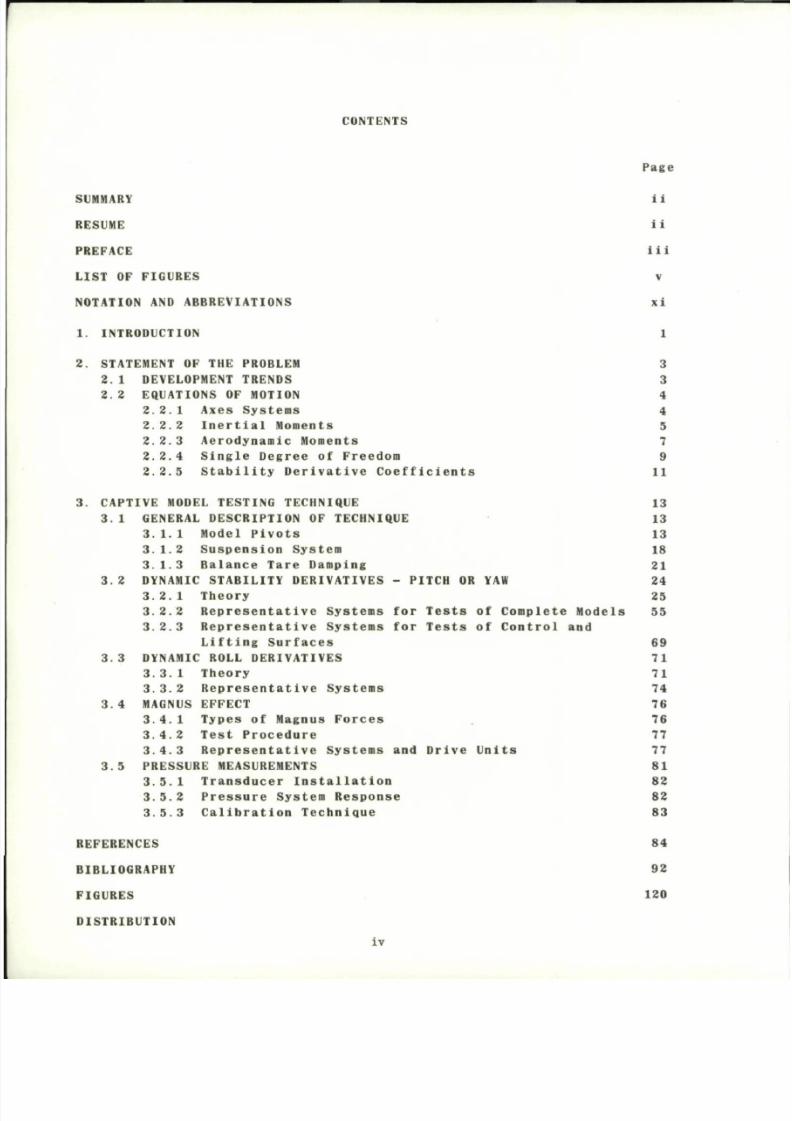
C O N T E N T S
P a g e
SUMMARY II
R E S U M E i i
P R E F A C E i i i
LIST OF FIGURE S V
NOTATION AND ABBREVIATIONS xi
1. INTROD UCTION 1
2. S T A T E M E N T O F T H E P R OBL E M 3
2.1 DEVELOP MEN T TRE NDS 3
2.2 EQUA TION S OF MOTION 4
2.2.1 Axes Sys tem s 4
2.2.2 Inerti al Mo me nts 5
2.2.3 Aero dynamic Mom ents 7
2.2.4 Single Degree of Freedom 9
2.2.5 Stabil ity Deri vati ve Coe ffic ients 11
3. CAP TIVE MODE L TESTING TEC HNIQUE 13
3.1 GENER AL DESCR IPTION OF TEC HNIQUE 13
3.1.1 Model Piv ots 13
3.1.2 Sus pensi on Syst em 18
3.1.3 Balance Tar e Dam ping 21
3.2 DYNAM IC STA BILITY DE RIVATIVES - PITCH OR YAW 24
3.2.1 Th eo ry 25
3.2.2 Rep rese ntative Syst ems for Test s of Comp lete Mode ls 55
3.2.3 Rep rese ntativ e Syst ems for Test s of Control and
Lifting Sur fac es 69
3.3 DYNAM IC ROL L DE RIVATIVES 71
3.3.1 The ory 71
3.3.2 Repr ese ntative Syst ems 74
3.4 MAG NUS EFFE CT 76
3.4.1 Type s of Magnus For ces 76
3.4.2 Test Pro ced ure 77
3.4.3 Repr esentat ive Syst ems and Drive Units 77
3.5 PRES SURE MEA SUR EME NTS 81
3.5.1 Tra nsduc er Insta lla tio n 82
3.5.2 Pres sure System Resp onse 82
3.5.3 Cal ib rat ion Te chnique 83
R E F E R E N C E S 84
BIBLIOGRAPHY 92
FIGURES 120
DISTRIBUTION
iv
8/10/2019 Techniques for Measurement of Dynamic Stability Derivatives in Ground Test Facilities
http://slidepdf.com/reader/full/techniques-for-measurement-of-dynamic-stability-derivatives-in-ground-test 7/236
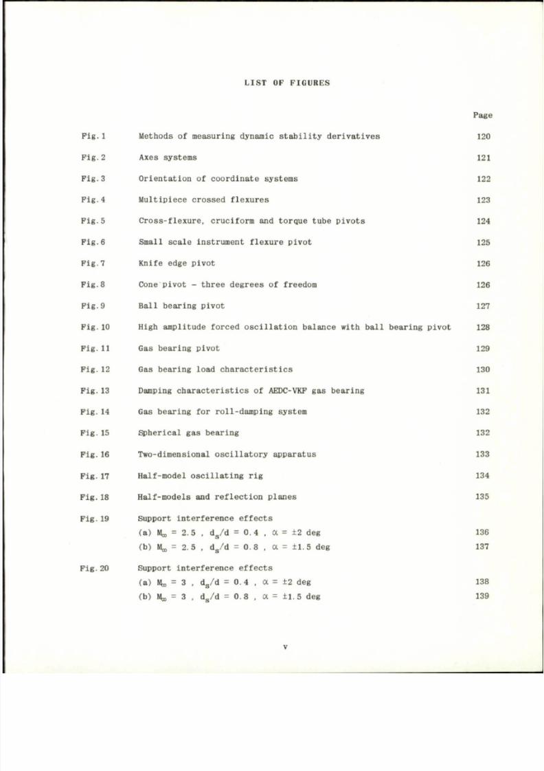
LI S T O F FI G U R E S
Page
Fig.1 Meth ods of measuring dynamic stability derivati ves 120
Fig .2 Axes syst ems 121
Fig.3 Orientation of coordinate systems 122
Fig.4 Multipiec e crossed flexures 123
Fig.5 Cross-flexure, cruciform and torque tube pivot s 124
Pig .6 Small scale instrument flexure pivo t 125
Pig .7 Knife edge pivot 126
Fig.8 Cone pivot - three degre es of freedom 126
Fig.9 Ball bear ing pivo t 127
Fig.10 High amplitude forced oscillat ion balance with ball bearing pivot 128
Fig .11 Gas bearing pivot 129
Pig. 12 Gas bearing load charac terist ics 130
Fig.13 Damping charact eristics of AEDC-VKF gas bearing 131
Pig .14 Gas beari ng for roll- damping system 132
Pig.15 Spherical gas bearing 132
Pig.16 Two-dimensional oscillator y apparatus 133
Fig.17 Half-m odel oscillating rig 134
Fig.18 Half-m odels and reflection planes 135
Pig.19 Support interference effects
(a) Ik = 2.5 . d
s
/d = 0.4 , a = ±2 deg 136
(b) Ik = 2.5 . d
s
/d = 0.8 , a = ±1.5 deg 137
Pig.20 Support interference effect s
(a) Ho = 3 , d
s
/d = 0. 4 , a = ±2 deg 138
(b) H,, = 3 . d
s
/d = 0.8 . a = ±1.5 deg 139
8/10/2019 Techniques for Measurement of Dynamic Stability Derivatives in Ground Test Facilities
http://slidepdf.com/reader/full/techniques-for-measurement-of-dynamic-stability-derivatives-in-ground-test 8/236
Page
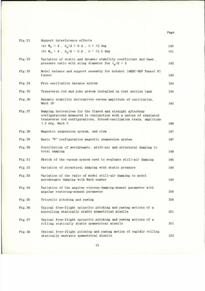
Pig. 21 Support interference effect s
(a) Ik = 4 , d
s
/ d = 0 . 4 . a = ± 2 d eg 140
(b) Ik = 4 , d
s
/d = 0.8 . a = ±1.5 deg 141
Pig. 22 Variation of static and dynamic stability coefficient and base
pressure ratio with sting diameter for Z
s
/d = 3 142
Fig. 23 Model balance and support assembly for hotshot (AEDC-VKP Tunnel P)
tunnel 143
Fig.
24 Free oscilla tion balance system 143
Pig.
25 Transverse rod and yoke system installed in test section tank 144
Pig.
26 Dynamic stability derivatives versus amplitude of oscillation,
Mac h 10 145
Fig.27 Damping derivatives for the flared and straight afterbody
configurations measured in conjunction with a series of simulated
transverse rod configurations, forced-oscillation tests, amplitude
1.5 deg , Mac h 5 146
Pig. 28 Mag netic suspe nsion system, end view 147
Fig. 29 Basic "V" configu rati on magnet ic suspe nsion system 147
Pig. 30 Contribution of aerodynamic, still-air and structural damping to
tota l dampi ng 148
Fig. 31 Sketch of the vacuum system used to evaluate still-air damping 148
Pig.
32 Variation of structural damping with static pressu re 149
Fig.
33 Variation of the ratio of model still-air damping to model
aerodynamic damping with Mach number 149
Fig. 34 Variation of the angular viscous- damping-moment paramete r with
angular restoring-moment para meter 150
Fig.
35 Tric ycli c pitc hing and yawing 150
Fig.
36 Typical free-flight epicyclic pitching and yawing moti ons of a
nonrolling statically stable symmetrical missi le 151
Pig.
37 Typical free-flight epicyclic pitching and yawing moti ons of a
rolling statically stable symmetrical missi le 151
Pig.
38 Typical free-flight pitching and yawing motion of rapidly rolling
statically unstable symmetrica l missile 152
vi
8/10/2019 Techniques for Measurement of Dynamic Stability Derivatives in Ground Test Facilities
http://slidepdf.com/reader/full/techniques-for-measurement-of-dynamic-stability-derivatives-in-ground-test 9/236
Page
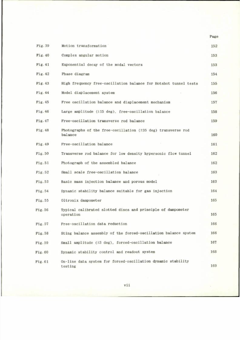
Fig.39 Moti on transformatio n
152
Pig.40 Comp lex angular motio n
153
Pig .41 Exponentia l decay of the modal vectors 153
Pig.42 Phase diagram 154
Pig.43 High frequency free-os cillat ion balance for Hotshot tunnel tests 155
Fig.44 Model displacement system
156
Pig.45 Free oscillati on balance and displac ement m echanism 157
Pig.46 Large amplitude
(±15
d e g ) ,
free-oscillation balance
158
Fig.47 Free-os cillat ion transvers e
rod
balance
159
Pig.48 Photographs of the free-oscillation (±35 deg) transverse rod
balance
160
F i g . 4 9 F r e e - o s c i l l a t i o n b a l a n c e 16 1
Pig .50 Tra nsv er se rod ba lan ce for low de ns i ty hyp er so nic f low tun nel 162
Fig .51 Photograph of the as sembled ba la nce 162
F i g . 5 2 S m a ll s c a l e f r e e - o s c i l l a t i o n b a l a n c e 163
Fig .53 Bas ic mass in je c t io n ba lan ce and porou s model 163
P i g . 5 4 D ynamic s t a b i l i t y b a l an ce s u i t a b l e f o r g a s i n j ec t i o n 164
Fi g. 55 O ltr on ix dampometer 165
F i g . 5 6 T y p i ca l c a l i b r a t e d s l o t t e d d i s c s and p r i n c i p l e o f d ampo mete r
opera t ion 165
F i g . 5 7 F r e e - o s c i l l a t i o n d a t a r e d u c t i o n 166
F i g . 5 8 S t i n g b a l an ce a s semb ly o f t h e f o r c ed - o s c i l l a t i o n b a l an ce s y st em 166
F i g . 5 9 S ma ll amp l i t u d e ( ±3 d eg ) , f o r c ed - o s c i l l a t i o n b a l an ce 167
Fig .6 0 Dynamic s t a b i l i t y co nt ro l and r ead out sys tem 168
F i g . 6 1 O n - l i n e d a t a s ys te m f o r f o r c e d - o s c i l l a t i o n d yn am ic s t a b i l i t y
t e s t i n g 1 6 9
v i i
8/10/2019 Techniques for Measurement of Dynamic Stability Derivatives in Ground Test Facilities
http://slidepdf.com/reader/full/techniques-for-measurement-of-dynamic-stability-derivatives-in-ground-test 10/236
Page
P i g . 6 2 C o n t r o l p a n e l f o r f o r c e d - o s c i l l a t i o n s y s te m 170
F i g . 6 3 F o r c e d - o s c i l l a t i o n b a l a n c e 1 71
P i g . 6 4 S ys te m b l o c k d i ag r am f o r f o r c e d - o s c i l l a t i o n b a l a n c e 172
F i g . 6 5 P h o t o g ra p h o f t h e f o rw a r d p o r t i o n o f t h e f o r c e d - o s c i l l a t i o n
ba la nc e mechanism 173
Pi g.6 6 Schem at ic v iew of model and dr iv in g- sy st em components 174
P i g . 6 7 D e t a i l s o f o s c i l l a t i n g m e ch an is m 175
F i g . 6 8 B l oc k d i ag r a m o f e l e c t r o n i c c i r c u i t s u s e d t o m e a su r e m od el
dis pla ce m en t of ap pl i ed moment 176
F i g . 6 9 F o r c e d - o s c i l l a t i o n d yn am ic s t a b i l i t y b a l a n c e 177
F i g . 7 0 Y a w - r o l l b a l a n c e a nd a c c e l e r o m e t e r s 178
F i g . 7 1 F o r c e d - o s c i l l a t i o n b a l a n c e w i t h e l e c t r o m a g n e t i c e x c i t a t i o n 179
P i g . 7 2 C uta wa y v ie w o f t o r s i o n a l f l e x u r e p i v o t w i t h s t r a i n g a g e s f o r
f o r c e d - o s c i l l a t i o n b a l a n c e w i th e l e c t r o m a g n e t i c e x c i t a t i o n 179
Fi g . 73 Mag net ic model sus pen sion system 180
Pi g.7 4 Cone model for ma gnet ic sus pe nsio n 181
P i g . 7 5 B a s i c L c o n f i g u r a t i o n m a g n e t i c s u s p e n s i o n s y s te m 1 81
P ig .76 Magne t i c susp ens ion sys t em 182
P ig .77 Magne t i c suspe ns ion work ing se c t io n . 7 i n . x 7 i n . hyp er son ic
wind tu nn el 183
F ig .78 Schemat i c d i ag ram o f t he susp ens ion magnet a r r ay o f a s i x -
component mag net ic wind tu nn el ba lan ce and sus pen sion system 184
F i g . 7 9 M odel s u b j e c t e d t o a f o r c e d o s c i l l a t i o n i n r o l l w h i l e s u sp e n de d
in th e s ix - componen t ba l a nce 185
F ig .80 View o f co n t ro l su r f ac e d r iv e 186
F i g . 8 1 A p p a r a tu s f o r e l e v a t o r o s c i l l a t i o n 187
F i g . 8 2 A p p a r at u s f o r e l e v a t o r o s c i l l a t i o n 188
F ig .83 Ske tch o f co n t ro l su r f ace p luc k ing mechan ism 189
v m
8/10/2019 Techniques for Measurement of Dynamic Stability Derivatives in Ground Test Facilities
http://slidepdf.com/reader/full/techniques-for-measurement-of-dynamic-stability-derivatives-in-ground-test 11/236
Page
P i g . 8 4 E l a s t i c mod el s u s p en s i o n and e l ec t r o m ag n e t i c o s c i l l a t o r f o r
o s c i l l a t i o n i n p i t c h 190
P i g . 8 5 F r e e o s c i l l a t i o n w i th a u t o m a t i c a l l y r e c y c l e d f ee d ba ck e x c i t a t i o n 191
P i g . 8 6 H a l f- mo d e l o s c i l l a t i n g r i g 192
Fig .87 Rol l -dam ping sys tem 193
Fig .88 Ai r be ar in g ro l l - dam pin g mechanism 193
F i g . 8 9 A i r b ea r i n g r o l l - d am p i n g b a l an ce 194
Fig .90 Dynamic s t ea dy - r o l l ba la nce 195
P i g . 9 1 F o r c e d - o s c i l l a t i o n b a l a n c e 196
P i g . 9 2 P i c t o r i a l d ra w in g , f o r c e d - o s c i l l a t i o n b a l a n c e 197
F i g . 9 3 I l l u s t r a t i o n s o f t h e v a r i o u s M agnus e f f e c t s
(a) Magnus for ce at low an gl es of at ta ck 198
(b) Magnus for ce at la rg e an gl es of at ta ck 198
(c) Magnus ef fe c ts on ca nte d f i n s 198
(d) Magnus ef fe c ts on dr ive n f i n s 198
F i g . 9 4 E f f ec t o f s p i n p a r ame t e r o n t h e M agnus c h a r a c t e r i s t i c s 199
Fi g. 95 Eff ect of boundary la ye r on th e Magnus for ce 200
Fig .9 6 E le c t r i c motor dr i ve Magnus force sys tem 201
Pig .97 Magnus force sys tem, tu rb in e dr ive w i th in th e model 201
Fig .98 Magnus force sys tem, tu rb in e dr ive w i th in th e model 202
Pi g.9 9 Magnus for ce ba lan ce 203
Fig .10 0 Magnus ro l l -da mp ing ba lan ce w i th a i r be ar i ng s 203
F i g . 1 0 1 V a r i a t i o n o f b ea r i n g t emp e r a t u r e w i t h s p i n r a t e f o r b y p as s
a i r co ol in g 204
P i g . 1 0 2 O i l m i s t l u b r i c a t i n g s y st em and o t h e r i n s t r u m en t a t i o n 2 05
Pig .10 3 Two typ es of Magnus ba lan ce gage se c t io ns
(a) Sandia s t r a in gage ba lan ce 206
(b) AEDC-VKP s t r a i n gage ba la nc e 206
i x
8/10/2019 Techniques for Measurement of Dynamic Stability Derivatives in Ground Test Facilities
http://slidepdf.com/reader/full/techniques-for-measurement-of-dynamic-stability-derivatives-in-ground-test 12/236
Page
Pig. 104 Compar ison of semiconductor and conventional gage outpu ts 207
Pig.105 Experimental response magnitude and phase- angle calibratio n for
1.38 in. of
0.030
in. nominal-diam eter tubing connected to a gage
3
vol ume of 0.02 in. for air at sea-lev el condit ions 208
Pig.106 Pump for sinusoidal oscilla ting pressur e 209
Fig.107 Cam-ty pe pulsat or calibra tor 209
8/10/2019 Techniques for Measurement of Dynamic Stability Derivatives in Ground Test Facilities
http://slidepdf.com/reader/full/techniques-for-measurement-of-dynamic-stability-derivatives-in-ground-test 13/236
NOTATION AND ABBREVIATIONS
N o t a t i o n
A r e f e r e n ce a r ea o r g en e r a l co n s t an t
C t o t a l d amp in g co e f f i c i en t o r g en e r a l co n s t an t
C
x
t a r e d ampin g co e f f i c i en t
C
A
(- C
X
) t o t a l a x i a l - f o r c e c o e f f i c i e n t , - 2F
x
/yq
D
V
(
2
;
A
C
c
c r o s s - w i n d co e f f i c i e n t , 2P
Y
/Po>VpA , (C
y
= C
c
)
C
D
t o t a l d rag co e f f i c i en t , 2D/Po,VgA
C
L
l i f t c o e ff ic ie n t , I h / p ^ K
C j r o l li n g - mo men t co e f f i c i en t , 2M
x
/Pa)VpAd
C
l p
BCj/B(Pd/2V
c
)
C
/ r
B C j / 3 ( r d / 2 V
c
)
C
l / 3
dC,/dyS
C
t/
g BCj /3(5d/2V
c
)
C j g * 3 C j / 3 S *
C„ pitching moment coefficient o f a mode l which
h a s
trlagonal o r greater
symmetry, 2M
y
-/
/
o
a
,VgAd
C
« p a
C
n p a
=
C
n r
C
m a
C
m a
—
=
s
=
C
mp/3
C
mq
"
C
n /3
"
C
n 4
C
M a
C
B
p i t c h i n g moment c o e f f i c i e n t , 2M
y
//Oa>V*Ad
C
mpr = 3 V
5
(
P d / 2 V
c '
3
'
r d / 2 V
c >
C
mp /
3 = 3
2
C
m
/ 3 ( P d / 2 V
c
)B ^
C
m p
4 = 3
2
C
m
/ 3 ( P d / 2 V
c
) 3 C f i d / 2 V
c
)
C .
a
= dC
ff l
/3(qd/2V
c
)
8/10/2019 Techniques for Measurement of Dynamic Stability Derivatives in Ground Test Facilities
http://slidepdf.com/reader/full/techniques-for-measurement-of-dynamic-stability-derivatives-in-ground-test 14/236
J
m/3
= 3C
m
/3/3
ma
ma
c
N
(-c
z
)
C
N ,
C
Na
C
N a
C
n
C
np
C
npq
C
n p a
C
npa
C
n r
C
n/3
C
n/3
= 3c
m
/Ba
= d C
m
/ d ( ad /2V
c
)
n o rm a l f o r c e c o e f f i c i e n
= BC
N
/B(qd/2V
(J
)
= dC
N
/Boc
= 3 c
N
/ 3 ( a d / 2 V
c
)
yawing moment c o ef f i c i e
= 3 C
n
/ d ( P d / 2 V
c
)
= d
2
C
n
/ d ( P d / 2 V
c
) d ( q d / 2 V
c
)
= 3
2
C
n
/ d ( P d / 2 V
c
) B a
= d
2
C
n
/d(Pd/2V
c
)d (6cd /2V
c
)
= 3 c
n
/ d ( r d / 2 V
c
)
= 3c
n
/3/?
= 3C
n
/BC3d/2V
c
)
'yR
D
d
d.
P
X
(-
P
A>
F
Y
.
V - ° »
V
c '
'z/AoV^
side force coeffi cient, 2P
y
/
/
c
a
,V
2
A
cycles
t o
damp
to a
given amplitude ratio
R
velocity o f sound in a cylindrical tube
drag force
o r
general constant
model reference length, base diameter
sting diameter
voltage
forces along
t h e XYZ axes,
respectively
frequency o f oscillation
xii
8/10/2019 Techniques for Measurement of Dynamic Stability Derivatives in Ground Test Facilities
http://slidepdf.com/reader/full/techniques-for-measurement-of-dynamic-stability-derivatives-in-ground-test 15/236
f ( 0 ) v i s c o u s d a m p i n g
a s a
f u n c t i o n
o f
0
f ( 0
o
) v i s c o u s d a m p i n g a s a f u n c t i o n o f 0
Q
H
x
, H
y
, H
z
m o m e n t s o f m o m e n t u m a b o u t t h e X , Y a n d Z
a x e s ,
r e s p e c t i v e l y
H a n g u l a r m o m e n t u m v e c t o r
I
x
, I
y
, I
z
m a s s m o m e n t s o f i n e r t i a a b o u t t h e X , Y a n d Z
a x e s ,
r e s p e c t i v e l y
i = / ( - I )
T ,
J , k
u n i t v e c t o r s
i n t h e X , Y a n d Z
d i r e c t i o n s , r e s p e c t i v e l y
i . j * , k
u n i t v e c t o r s
i n t h e X , Y a n d Z
d i r e c t i o n s , r e s p e c t i v e l y
J
z x
. J
x y
, J
y z
p r o d u c t s
o f
i n e r t i a
K t o t a l s t i f f n e s s
K j f l e x u r e s t i f f n e s s
L l i f t f o r c e
I m o d e l l e n g t h
o r
t u b i n g l e n g t h
l
3
s t i n g l e n g t h
o f
c o n s t a n t d i a m e t e r
H v e c t o r r e s u l t a n t
o f t h e
e x t e r n a l m o m e n t s a c t i n g
o n t h e
m o d e l ,
( M
X
T
+ M
y
J +
M
z
k )
o r ( M
x
t + M
y
5 + M
z
£ )
M m o m e n t a b o u t
Y
a x i s
( M
y
)
M j o u t - o f - p h a s e m o m e n t
M
r
i n - p h a s e m o m e n t
M
x
, M
y
, M
z
m o m e n t s a b o u t
t h e X , Y a n d Z
a x e s , r e s p e c t i v e l y
M
X p
=
d M
x
/ d P
M
x S
*
= B M
X
/ B S *
M
&
=
B M
y
/ B < 5 c
U
e
= BM
y
/B0
U g = BM
y
/B(9
I L ^ , f r e e - s t r e a m M a c h n u m b e r
x l i i
8/10/2019 Techniques for Measurement of Dynamic Stability Derivatives in Ground Test Facilities
http://slidepdf.com/reader/full/techniques-for-measurement-of-dynamic-stability-derivatives-in-ground-test 16/236
n number
P.Q.R scalar components
of cd in
the
X
,
Y and Z
directions
(P = P
0
+ P, Q = q
0
+
q.
R
= r
0
+ r)
P =
P d / 2 V
C
P
s
s t e a d y - s t a t e r o l l i n g v e l o c i t y
p , q , r p e r t u r b a t i o n s of P.Q.R
P
t
i n p u t p r e s s u r e
p,,,
m e a su re d p r e s s u r e at gage
P
b
mode l base p r es su re
Pa,
free-stream static pressure
p m e a n p r e s s u r e
O o ,
f r e e - s t r e a m d y n a m i c p r e s s u r e
R r a t i o
o f
f i n a l a m p l i t u d e
t o
I n i t i a l a m p l i t u d e
R e f r e e - s t r e a m u n i t R e y n o l d s n u m b e r
r t u b i n g r a d i u s
o r
r a d i a l d i s t a n c e
t t i m e
U . V . W s c a l a r c o m p o n e n t s
o f
V
c
in th e
X
,
Y
a n d
Z
d i r e c t i o n s
( U
= u
Q
+
u ,
V = v
0
+
v ,
W - w
0
+ w)
u , v , w p e r t u r b a t i o n s of U,V,W
V
c
or V
v e l o c i t y
o f t h e
m o d e l c e n t e r - o f - g r a v i t y w i t h r e s p e c t
t o t h e
m e d i a
(Ul + v j + wk, v
0
=
w
0
=
0)
V volume
of
pressure gage
V
t
volume of tube
XYZ body-fixed axes system (Pig.3)
or
components
of
external forces
X
e
Y
e
Z
e
earth-fixed axes system (Fig.2)
X Y Z nonrolllng axes system (Fig.3)
X.Y
Z„
stability axes system (Fig.2)
o S S
xiv
8/10/2019 Techniques for Measurement of Dynamic Stability Derivatives in Ground Test Facilities
http://slidepdf.com/reader/full/techniques-for-measurement-of-dynamic-stability-derivatives-in-ground-test 17/236
X
T
Y
T
Z
T
tunnel-fixed axes system (Inertial refe rence. Fig ure 3)
X
W
Y
W
Z
W
wind axes system (Fig.2)
x,z transfer distance
x
c g
distance from
the
model nose
to the
model piv ot axis (rearward po sit ive)
a angle
o f
attack
/3 a n g l e o f s i d e s l i p
y r e f e r e n c e p h a s e a n g l e
A
log
d e c r e m e n t
B *
c o n t r o l s u r f a c e d e f l e c t i o n a n g l e
0 I n s t a n t a n e o u s a n g u l a r d i s p l a c e m e n t f r o m t h e r e f e r e n c e f l i g h t c o n d i t i o n
0± o u t - o f - p h a s e p o s i t i o n
0
Q
o s c i l l a t i o n p e a k a m p l i t u d e
o r
i n i t i a l a m p l i t u d e
0
T
i n - p h a s e p o s i t i o n
A. d a m p i n g r a t e
p
v i s c o s i t y
p
w
f r ee - s t r e am o r amb i en t d en s i t y
£ complex ang le of at ta ck (v + iw)/V
c
o r , f o r s ma l l an g u l a r d i s p l a ce
m en ts, /3 + ioc
< p a r b i t r a r y p h a se a n g l e o r r o l l p e r t u r b a t i o n
X
H,0 ,$ Eule r ang les ; ang les of yaw, p i t c h and ro l l . F ig ure 2(b)
(? = 0
O
+ 0 . 0 = 0
O
+ 0. $ = 0
O
+ cp)
ip,0.4> p e r t u rb at io n s of * , 0 , $
H v ec t o r an g u l a r v e l o c i t y o f t h e n o n - r o l l i n g co o r d i n a t e s y st em w i t h
r e s p ec t t o i n e r t i a l s p ace (O i + q j + r k )
c o an g u l a r c i r c u l a r f r eq u en cy
co. n a t u r a l damped c i r c u l a r f r eq u en cy
lo v ec t o r an g u l a r v e l o c i t y o f t h e b od y co o r d i n a t e s y st em w i t h r e s p e c t t o
i n e r t i a l s p ace (P i + q j + r k , q
0
= r
0
= 0)
xv
8/10/2019 Techniques for Measurement of Dynamic Stability Derivatives in Ground Test Facilities
http://slidepdf.com/reader/full/techniques-for-measurement-of-dynamic-stability-derivatives-in-ground-test 18/236
<ad/2V„
( ' ). C )
(")
n
Subscripts
a
t
E
i
i o r 2
Abbreviations
AEDC
PWT
VKF
AGARD
BRL
DTMB
HSD
LRC
LTV
reduced frequency parameter
first
a nd
second derivati ves with respect
t o
time
t
vector notation
nonrolling coordinate system notation
aerodynamic
tare
effective values
initial conditions
local values
Initial pitch axis
o r
refer ence flight conditi ons
new pitch a x e s , times,
o r
nutatio n
and
precession mode s
wind
on
vacuum
free-stream
Arnold Engineering Development Center
( U S A i r F o r c e ) ,
Arnold Center,
Tennessee.
Propulsion Wind Tunnel Facility, AEDC.
von Karman
G a s
Dynamics Facility, AEDC.
Advisory Group
f o r
Aerospace Research
and
Development,
a
Division
o f
the North Atlantic Treaty Organization, NATO.
Ballistic Research Laboratory, Aberdeen Proving Ground, Maryland.
David Taylor Model Basin (US N a v y ) , Carderock, Maryland.
Hawker Siddeley Dynamics Ltd, Coventry, England.
Langley Research Center ( N A S A ) , Langley Field. Virginia.
Ling-Temco-Vought A erospace Corporati on, Dallas, Texas.
xv 1
8/10/2019 Techniques for Measurement of Dynamic Stability Derivatives in Ground Test Facilities
http://slidepdf.com/reader/full/techniques-for-measurement-of-dynamic-stability-derivatives-in-ground-test 19/236
MIT Massachus etts Institute of Technology, Cambridge , Massachuse tts.
NACA National Advisory Commit tee on Aeronautic s (now the National Aero
nautics and Space Agency,
N A S A ) .
NAE National Aeronautical Establi shment, Ottawa, Canada.
NASA National Aeronautical and Space Agency, Washington, DC.
NOL Naval Ordnance Laboratory, White Oaks , Maryland.
OAL Ordnance Aerophy sics Laboratory, Dangerfield, Texas.
ONERA Off ice National d'Etudes et de Rec her che s Ae'rospatiales (National
Bureau of the Aerospace
Research),
Paris, France.
PU Princeton University, Princeton, New Jersey.
RAE Royal Aeronautical Establish ment, Farnborough, Hants, England.
SU Southampton University, Southampt on, England.
UC University of California, Berkeley, California.
UM University of Michigan, Ann Arbor, Michigan.
WADD Wright Air Development Division, Wright-Patters on Air Force Base,
Ohio.
xvli

8/10/2019 Techniques for Measurement of Dynamic Stability Derivatives in Ground Test Facilities
http://slidepdf.com/reader/full/techniques-for-measurement-of-dynamic-stability-derivatives-in-ground-test 20/236
8/10/2019 Techniques for Measurement of Dynamic Stability Derivatives in Ground Test Facilities
http://slidepdf.com/reader/full/techniques-for-measurement-of-dynamic-stability-derivatives-in-ground-test 21/236
S E C T I O N 1
INTRODUCTION
Analysis o f aircraft and missile aerodynamic performance and stability requires
knowledge o f t h e forces and mome nts which act under conditions o f steady and unsteady
flight. One of the first studies o f aircraft stability wa s that of Lanchester
1
around
1900, followed later by more complete and rigorous analysis by Bryan
2
, which is still
the basis for much of the dynamic stability work today.
Requirements for supplying a erodynamic charact eristic s for perfor mance analysis
have been met, to some extent, by relying on theories supported by experimental m easure
ments t o establish t he validity o f t h e theories. In some cases, th e theory h a s only
limited application especially when viscous flow h a s a pro nounced influence on the
flow field, as in the case o f high speed flow (hypersonic speeds and above) and low
Reynolds numbers. There are some situations for which the phenom ena cannot be described
adequately by theory. In other cases theory is not applicable because th e configuration
and flow field are so complex that t h e many approximations required invalidate a wholly
theoretical approach.
Thus,
in prac tice , strong reliance is placed on experimental
results for use in analyzing th e modes of motion o f t h e aircraft o r missile.
Early experimental techniques making u s e o f oscillating models to dynamically simulate
rigid modes o f motion for determining stability derivati ves are well summari zed by
Jones
3
.
It is of interest t o note that no fundamental changes in the basic experimental
methods ha ve taken place since that ti me, 1934, although much work h a s been done toward
refinement o f t h e metho ds, equipment and instrumentation. Little emphasis wa s placed
on dynamic stability experiments until about 1940, a nd from that time to 1945 experi
mentation wa s primar ily concerned with subsonic flow and tests were made for small
perturbat ions. Wind tunnel experiments and flight tests within t h e early forties were
directed more toward static stability and control problem s. With t h e advent of high
speed aircraft, missiles, rockets, and re-entry vehicles , increased emp hasis h a s been
placed
on
performance
and
dynamic stabil ity pro blem s since missions demand precis e
control
no t
only
in
small disturba nces from level flight,
but
also
in
large scale
maneuvers. A s a result, dynamic stabil ity measu rements have become increasingly important
at supersonic, hypersonic and hypervelocity speeds and at large perturbations. T h e
experimental methods suggested by earlier experiments have been used in different forms,
and many improvements have been made in the experimental techniques since about 1950.
These improvements have been in the areas o f balance system, model and support system
design, instrumentation, data acquisition, and data reduction.
In 1954 Valensi
4
presented a review o f t h e techniques primari ly in use in Europe for
measuring oscillatory aerodynamic forces and moments o n models oscillating in wind
tunnels.
Th e following year AGARDograp h 11
(Ref. 5)
by Arnold wa s published on the
subject of dynamic me asurements in wind tunnels. T he most recent summary o f techniques
8/10/2019 Techniques for Measurement of Dynamic Stability Derivatives in Ground Test Facilities
http://slidepdf.com/reader/full/techniques-for-measurement-of-dynamic-stability-derivatives-in-ground-test 22/236
for measuring oscillatory derivatives in wind tunnels was published by Bratt
6
in 1963
as a part of the AGARD Manual on Aeroelasticity. The paper discus ses the basic principles
employed in measuring derivat ives and gives some account of the associated instrumentation.
Much of the report deals with the methods and instrumentation employed in England.
Since these earlier works, the emphasis on dynamic stability testing has increased,
and many reports have been prepared on the subject, so there exists a need for a review
and summary of the current dynamic stability testing techniques in use at supersonic
speeds and above.
There are many experimental techniques which are suitable for measuring dynamic
stability d erivati ves; however, only those techniques that are in most common use in
wind tunnels will be described. In addition, many different systems exist for measuring
the same quantities and, since they differ primarily in the specific application, no
attempt will be made to describe all systems; only systems considered to be representa
tive and those having unique features will be discussed. The report is organized
primarily around the aspects of dynamic stability testing in wind tunnels at supersonic
speeds and abov e, although m uch of the report is pertinent to aspec ts of testing at
transonic and subsonic speeds. Although free -flight testing in ground test facilities
encompasses the use of the wind tunnel and aeroballistlc range for measurements of
dynamic stability derivative s, these t echniques are not included as a part of th is
AGARDograph because other publications on these subjects have been published and are
in preparat ion
7, 8
.
8/10/2019 Techniques for Measurement of Dynamic Stability Derivatives in Ground Test Facilities
http://slidepdf.com/reader/full/techniques-for-measurement-of-dynamic-stability-derivatives-in-ground-test 23/236
S E C T I O N 2
S T A T E M E N T O F T H E P R O B L E M
2. 1 D E V E L O P M E N T T R E N D S
Aircraft or missiles in high speed flight are free to respond to disturbances with
motio ns involving many degrees of freedom. During vari ous stages of aerodynamic design
of a vehicle, as the configuration is developed, dynamic chara cteristics must be known
and progressiv ely refined to a high degre e for the final configura tion performa nce
specification. The designer must necessarily be concerned with the interpretation of
aerodynamic stability data and with the evaluation of the influence of their accuracy
on an integrated system design.
There are three methods of obtaining stability data:
(i) Theory and empirical data,
(li) Wind tunnel and aer oballistic range model testi ng,
(iii) Sub- or full-s cale flight testi ng.
During the preli minary design stage, it is most expedient to rely primar ily on theory
and empirical data for performance evaluation whereas, in the later stages, design
concepts inevitably require evaluation through the use of some scale model tests. As
a final phase in the design development, sub- or full-scale flight tests are required
to verify performance and obtain in-flight measurements for verification of theory and
prediction methods.
There are certain speed regimes where theoretical results may be inaccurate due to
insufficient or inaccurate basic data. For example, in the transonic speed regime
(0.9 < Mo, < 1. 5) theoretical meth ods for dete rmining dynamic stab ility deriv ative s are
very limited, and, therefore, reliance is place d on methods involving the use of
empirical data on similar configurations and correlation plots showing the manner in
which the stability derivatives vary with Mach number for similar configurations.
Within the superso nic and hypers onic regio n (1.5 < M^, < 10), theoreti cal met hods
are available for estimating der ivatives for bodies of revolution and relatively simple
lifting configuratio ns. At Mach numbers above 10 in the hypervelocit y speed regime,
theories generally fail to predict the derivatives because visc ous effects have a
strong influence on the vehicle aerodynamic characteristics.
In order to Improve the accuracy of aerodynamic de rivat ives that are used in per
formance pre dic tions and to validate theoret ical estima tes, model tes ts in ground test
facilities are recognized as being essential to the development of aircraft, missiles
and re -entry vehic les.
8/10/2019 Techniques for Measurement of Dynamic Stability Derivatives in Ground Test Facilities
http://slidepdf.com/reader/full/techniques-for-measurement-of-dynamic-stability-derivatives-in-ground-test 24/236
Study of vehicle motions in flight involves consideration of many degrees of freedom.
When the vehicle is considered as a rigid body, six degrees of freedom are required.
Since the vehi cle is not a rigid stru cture, additional relati ve motio ns of components
such as aeroelastic deflection of lifting surfaces and movable controls constitute
additional degrees of freedom.
The vehicle motions may be separated into high frequency and low frequency motions,
where high frequency motio ns studies such as flutter are primarily concerned with
structural elastici ty and unsteady aerodynamics. At low frequencies the moti ons involve
rigid body motions and are studied as dynamic stability using quasi-static aerodynamics.
The mode of model testing discusse d in the present A GARDog raph is concerned with this
latter type motion and the determination of rotary damping derivatives.
In scaling down a vehic le for model t ests the paramet er tha t must be considered in
addition to the Mach number and Reynolds number is the angular velocity or frequency
of model oscillat ion in relation to full-scal e conditions. The scaling param eter,
called the reduced frequency, in the form cdd/2Va, contains the frequency of oscilla tion
and represents the ratio of some characteristic dimension of the vehicle to the wave
length of the oscillation. This type of scaling parameter also applies to dynamic roll
tests and has the form Pd/2Vo, .
Experimental techniques for measuring dynamic stability derivatives in ground test
facili ties may be classified in many different ways. The classifica tion that will be
followed here is presented in Figur e 1. The two major classi ficati ons are derived on
the basis of whether the model is free to move in all basic degrees of freedom or
whether it is restricted in several degre es of freedom. The sub topics shown in Figure 1
for discussion were selected as those methods currently being employed for most high
speed testing; however, it should be emphasized that the outline does not show the case
of the model fixed in the test section with pert urba tions generated in the flow. As
noted in the Introduction, only those methods which apply to captive model testing
techniques will be discussed in this AGARDograph since free-flight tests in the wind
tunnel and range are the subject of AGARDographs published and now in preparation
7, 8
.
Additional general information on meth ods not described herein may be found in Reference 9.
2. 2 E Q U A T I O N S O F M O T I O N
In order to place the role of dynamic stability testing in perspective, it is helpful
to examine the equations of motion. Although the mathe matica l treatment of vehicle
dynamics is well known and found in many te s t s
10
'
12
, a brief derivation of the equations
of motion is included to illustrate the basis for the experimental techniques used in
the study of dynamic stability.
2.2.1 Axes Sys tem s
The equations of motion will be developed using the axes systems shown in Figures 2
and 3. Model orientation is determined relati ve to the tunnel fixed axes X
T
Y
T
Z
T
(inertial reference). The XYZ axes are fixed in the model with the X and Z axes
in the model's plane of symmetry. When the origin of this system lies at the center
of gravity, these axes are then defined as the body axes. The angular orientation of
the XYZ system with respect to the X
T
Y
T
Z
T
system and inertial space is given by the
8/10/2019 Techniques for Measurement of Dynamic Stability Derivatives in Ground Test Facilities
http://slidepdf.com/reader/full/techniques-for-measurement-of-dynamic-stability-derivatives-in-ground-test 25/236
Euler angles ¥ , 0 , and $ . Somet imes it is convenient to use the nonrolli ng axes
system (XYZ). Thes e are special body axes whose angular orientation in space relative
to the X
T
Y
T
Z
T
system is determined by the angles ? and 0 . This axis system can
be used even though the model is rotating about the X
axis.
The origins of all
systems are assumed to occupy the same point in space
(Pig.3).
2.2.2 Inertial Mom ents
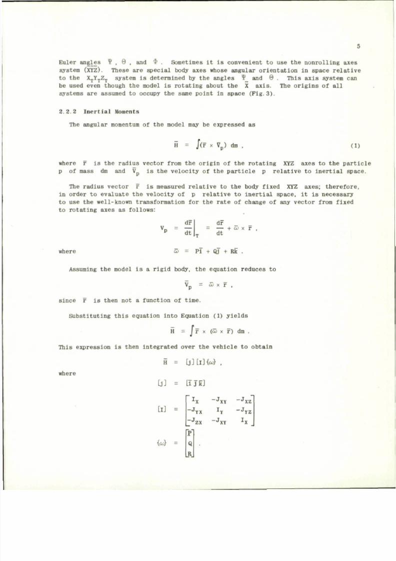
The angular momentum of the model may be expressed as
H = /(r x V
p
) dm ,
(1)
where r is the radius vector from the origin of the rotating XYZ axes to the parti cle
p of mass dm and V is the velocity of the particle p relative to inertial space.
The radius vector r is measured relative to the body fixed XYZ
axes;
therefore,
in order to evaluate the velocity of p relative to inertial space, it is necessary
to use the well-known transformation for the rate of change of any vecto r from fixed
to rotating axes as follows:
dr
V
P
= dT
dF
= — + co x r ,
dt
where
Pi + Qj + Rk
Assuming the model is a rigid body, the equation reduces to
V = co x r ,
since r is then not a function of time.
Substituting t his equation into Equation (1) yie lds
H = J F x (co x F) dm .
This expression is then integrated over the vehicle to obtain
fi = L j ] [ i ] W .
where
[j]
=
LiJkJ
[I] -
{co} =
-J
-J
P"
Q
R
YX
ZX
-J
XY
-J
Y
-J
- J
xz
yz
8/10/2019 Techniques for Measurement of Dynamic Stability Derivatives in Ground Test Facilities
http://slidepdf.com/reader/full/techniques-for-measurement-of-dynamic-stability-derivatives-in-ground-test 26/236
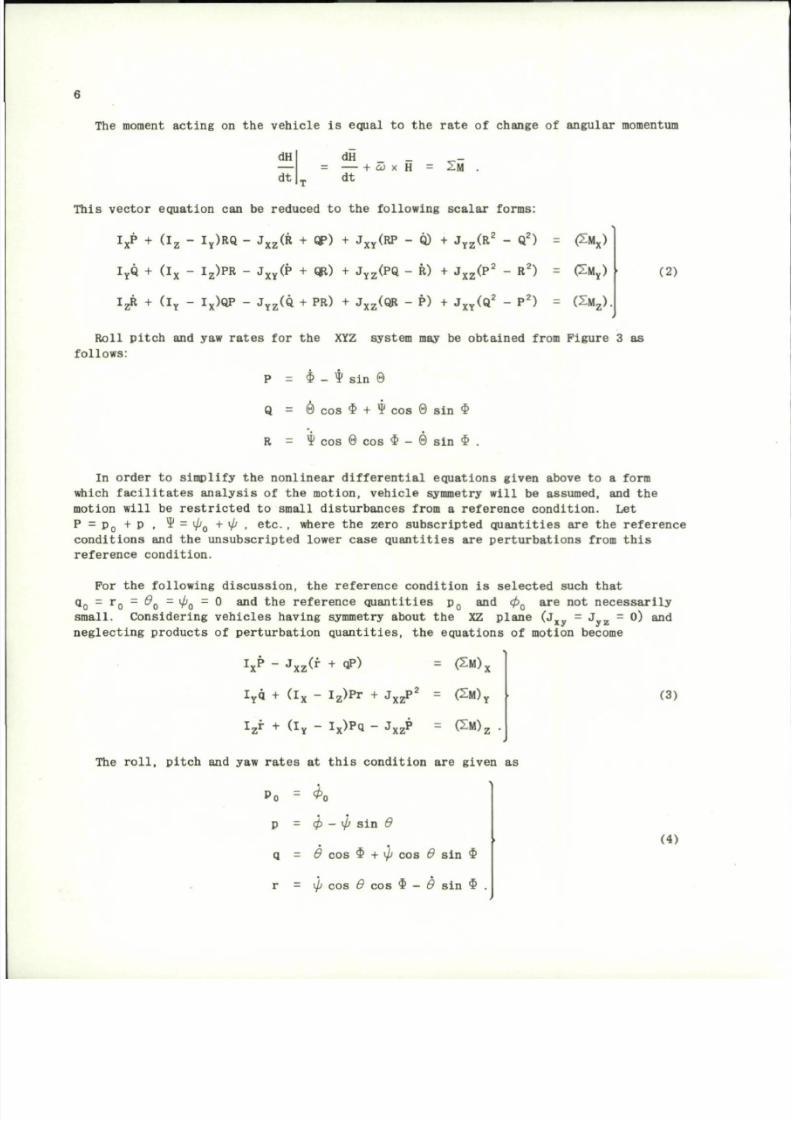
The moment ac t i ng on th e ve hi cl e i s eq ual to th e r a te of change of angu lar momentum
2M .
H
d t
dH _ _
= — + w x H
d t
Th i s ve c to r equa t io n can be r educed to t he fo l low ing s ca l a r f o rms:
I
X
P + ( I
z
- I
y
)RQ - J
X Z
(R + QP) + J
X Y
(RP - 0) + J
Y Z
(R
2
- Q
2
) = £ M
X
)
I
Y
Q + ( I
x
- I
Z
)PR - J
X Y
(P + QfO + J
Y Z
(PQ - R) + J
X Z
( P
2
- R
2
) = £M
Y
)
I
Z
R + ( I
Y
- I
X
)QP - J
V 7
(Q + PR) + J
Y 7
(QR - P) + J
Y V
(Q
2
- P
2
) (2M
7
) .
'YZ
V
'xz
N
'XY'
(2)
Roll pitch
and ya w
rates
for the XYZ
system
may be
obtained from Figure
3 as
follows:
P
= $ - * sin 0
Q = 0 cos $ + ¥ cos 0 s in $
R
=
y cos
0 cos $ - 0 sin $ .
In orde r
to
simplify
t h e
nonlinear differential equations given above
to a
form
which facilitates analysis o f t he motio n, vehicle symmetry will be assumed, and the
motion will be restricted to small dist urbances from a reference condition. L e t
P = P
0
+ P ,
¥ =
0 + 0 .
e
t c. , where
th e
zero subscripted quantities
a r e t h e
reference
conditions and the unsubscripted lower case quantities are perturbations from this
reference c ondition.
For t h e following discuss ion, the reference condition is selected such that
q
0
= r
0
=
0
Q
=
0
O
= 0 and the
reference quantities
p
0
and
cp
Q
are not
necessarily
small. Considering vehic les having symmetry about t h e X Z plane ( J
w
„ = J „ „ = 0) and
xy y z
n e g l e c t i n g p r o d u c t s o f p e r t u r b a t i o n q u a n t i t i e s , t h e e q u a t i o n s o f m o t io n beco me
V "
J
x z< r + QP)
= £M),
I
y
q + ( l
x
- I
z
) P r + J
X Z
P
2
= ( 2 M )
Y
I
z
r + ( I
Y
- I
x
)Pq - J
X Z
P = (2M)
Z
T he r o l l , p i t c h a nd yaw r a t e s a t t h i s c o n d i t i o n a r e g i v e n a s
Po = ^o
p = cp - \p s in 0
q = 0 co s $ + 0 cos 0 s i n $
r = yi co s 0 co s $ - 0 si n $ .
(3)
(4)
8/10/2019 Techniques for Measurement of Dynamic Stability Derivatives in Ground Test Facilities
http://slidepdf.com/reader/full/techniques-for-measurement-of-dynamic-stability-derivatives-in-ground-test 27/236
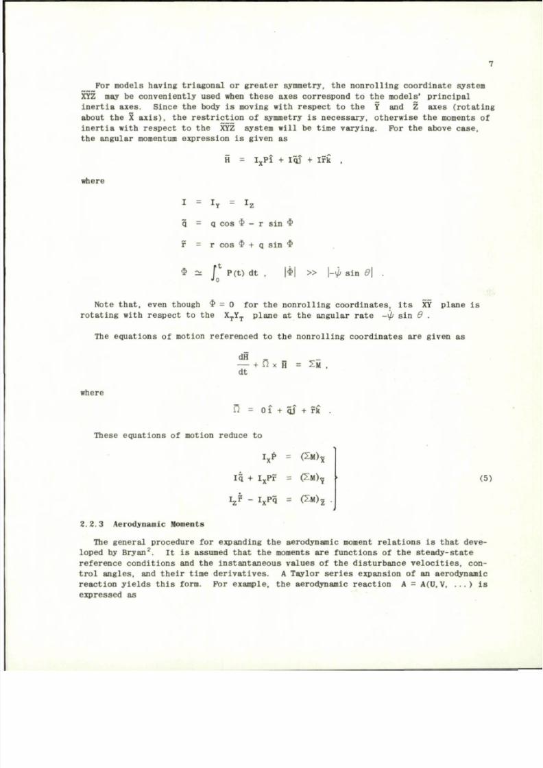
For models having triagonal or greater symmetry, the nonrolling coordinate system
XYZ may be conveniently used when these axes correspond to the mode ls' principal
inertia axes. Since the body is moving with respect to the Y and Z axes (rotating
about the X axis), the restriction of symmetry is necessary, otherwise the moments of
inertia with respect to the XYZ system will be time varying. For the above case,
the angular momentum expression is given as
H
I
Y
Pi + Iqj + Irk ,
where
I = I
Y
= I
z
q - q cos $ - r sin $
r = r cos $ + q sin $
$ ~ f P(t) dt , 1*1 » \-\b sin 0\
Jo
Note that, even though $ = 0 for the nonrolling coordi nates, its XY plane is
rotating with respect to the X
T
Y
T
plane at the angular rate -xft sin 0 .
The equations of motion referenced to the nonrolling coordinates are given as
dH .
— + n x
H
=
S M
,
dt
where
M
O i + qj + rk .
These equations of motion reduce to
13 +
l i * -
I * *
I
X
PF
I
x
P q
=
=
=
(2M)
X
( 2 M )
?
( 2 M )
2
(5)
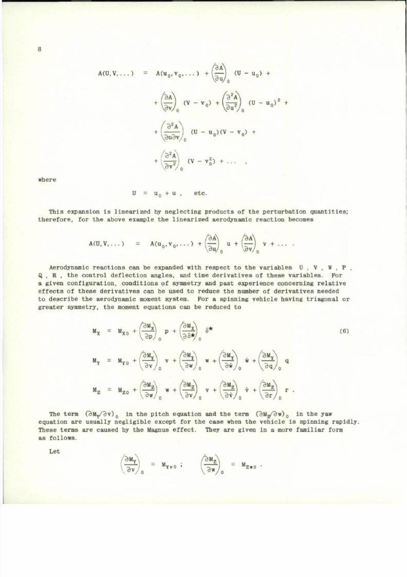
2.2.3 Aerod ynamic Mome nts
The general pr ocedure for expanding th e aerodynamic moment relat ions is that deve
loped by Bryan
2
. It is assumed that the moments are functions of the steady-state
reference conditions and the instantaneous value s of the distur bance veloci ties, con
trol angles, and their time derivatives. A Taylor series expansion of an aerodynamic
reaction yields this form. For example, the aerodynamic reaction A = A(U.V, ... ) is
expressed as
8/10/2019 Techniques for Measurement of Dynamic Stability Derivatives in Ground Test Facilities
http://slidepdf.com/reader/full/techniques-for-measurement-of-dynamic-stability-derivatives-in-ground-test 28/236
A(U,V,...)
=
A (u
0
, v
0
. . . . )
+ — (U - u
0
) +
i
Buy
o
+
( B T )
0
( V
-
V
°
) +
( S )
0
( U
-
U
O >
2 +
B
2
A \
(U
- u
Q
)(V -
v
Q
)
+
\ B u B v /
0
2
^
2 I
v
' ' 0 '
B
2
A \
where
\Bv
U
= u
0
+ u , etc.
This expansion is linearized by neglecting products of the perturb ation quantities;
therefore,
for the
above example
the
linearized aerodynamic reaction be comes
A(U,V,...) A(u
n
. v
n
, . . . ) f (—
1
u + I — I v + ... .
Aerodynamic reactions
can be
expanded with respect
t o t h e
variables
U
,
V , W
,
P ,
Q , R , the control d eflecti on angles, and time derivatives o f these variables. For
a given configuration, conditions
of
symmetry
and
past experience concerning relative
effects o f these derivatives can be used to reduce the number of derivatives needed
to describe
the
aerodynamic moment system.
F o r a
spinning vehicle having t riagonal
or
greater symmetry, the moment equations can be reduced to
M
x =
M
xo + l - ~ \ P + (r r r ) 8*
VWo w
)M
Y
\ /B M
Y
\ / 3 M
Y
\ /BM
Y
The term (BM
Y
/Bv)
0
in th e p i t c h equ at io n and th e term (BMg/Bw),, in th e yaw
e q u a t i o n a r e u s u a l l y n e g l i g i b l e e x c e p t f o r t h e c a s e w hen t h e v e h i c l e i s s p i n n i n g r a p i d l y .
These term s are caused by th e Magnus ef fe ct . They ar e g iven in a more fa m i l ia r form
a s f o l l o w s .
Let
< * ) ,
'
YV
° ' W o "
Z
'°
8/10/2019 Techniques for Measurement of Dynamic Stability Derivatives in Ground Test Facilities
http://slidepdf.com/reader/full/techniques-for-measurement-of-dynamic-stability-derivatives-in-ground-test 29/236
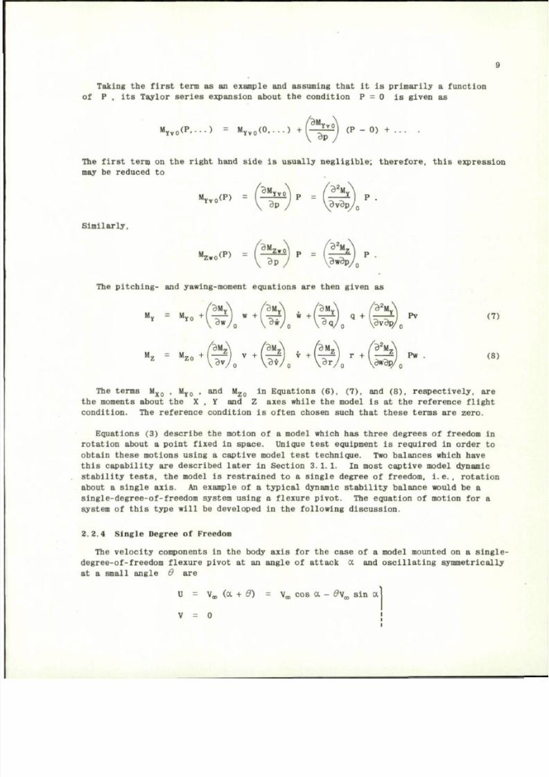
Taking th e first term as an example and assuming that it is primar ily a function
of P , its Taylor series expansion about the condition P = 0 is given as
'BM
M
Yv 0
( P....) = M
Yv 0
( 0. . . . ) +( - ^ ) (P - 0) +
v O l
Bp
The first term on the right hand side is usually negligible; therefore, this expression
may be reduced to
BM
Y
T
P
M
Yvo<
p
) -rr^J
Similarly,
The pitching- and yawing-moment equatio ns are then given as
/ B M
Y
\
/ BM
Y
\ / B M
V
\ /B
2
M
V
"•
= M
K I 7 ) /
+
( l r )
0
i +
^ '
r + l
^' "•
m
The terms M
x o
, M
Y 0
, and M
z o
in Equations ( 6), (7), and (8), respectively, are
the moments about the X , Y and Z axes while the model is at the reference flight
condition. The reference condition is often chosen such that these terms are zero.
Equations (3) describe the motion of a model which has three degrees of freedom in
rotation about a point fixed in space . Unique test equipment is required in orde r to
obtain these moti ons using a captive model test technique. Two balances which have
this capability are described later in Section 3.1.1. In most capti ve model dynamic
stability tests, the model is restrained to a single degree of freedom, i.e., rotation
about a single
axis.
An example of a typical dynamic stability b alance would be a
single-degree-of-freedom system using a flexure pivot. The equation of motion for a
system of this t ype will be developed in the following discussion.
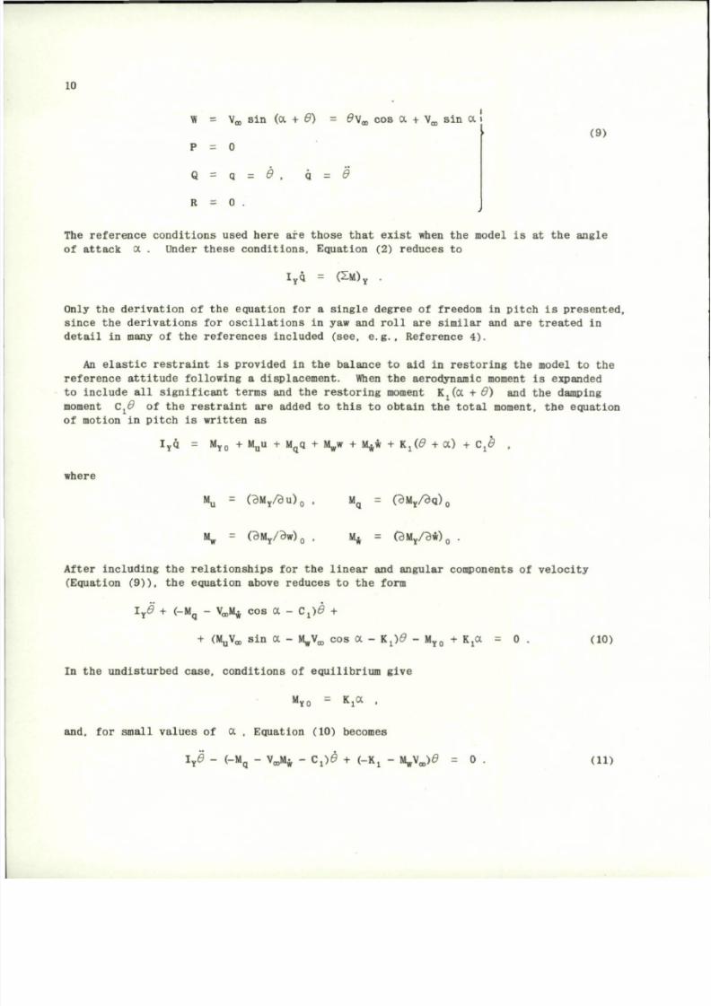
2.2.4 Single Degree of Freedom
The velocity components in the body axis for the case of a model mounted on a single-
degree-of- freedom flexure pivot at an angle of attack a and oscilla ting symm etrically
at a small angle 0 are
u - \
w
(a + d ) = Va , cos a - d \
m
sin a
V = 0
i
8/10/2019 Techniques for Measurement of Dynamic Stability Derivatives in Ground Test Facilities
http://slidepdf.com/reader/full/techniques-for-measurement-of-dynamic-stability-derivatives-in-ground-test 30/236
10
W
s
Vo,
sin (a + d) - d v
w
cos a + V^ sin a
i
(9)
P = 0
Q = a = £ . ii = 0
R = 0 .
The reference conditions used here
are
those that exist when
the
model
is at the
angle
of attack oc . Under these conditions. Equation (2) reduces to
I
Y
q =
( 2 M )
Y
.
Only the derivation of the equation for a single degree of freedom in pitch is presented,
since the derivations for osci llations in yaw and roll are similar and are treated in
detail
in
many
of the
refere nces included (see,
e.g.,
Reference 4) .
An elastic restraint
is
provided
in the
balance
to aid in
restori ng
the
model
to the
reference attitude following a displac ement. When the aerodynamic moment is expanded
to include all significant terms and the resto ring moment Kj((X +
0 )
and the damping
moment C.6 of the restra int are added to this to obtain the total moment, the equation
of motion in pitch is written as
I
Y
q = M
Y0
+ M
u
u + M
q
q +
\ v +
M^w + Kj(0 + a ) +
C
x
0
.
where
M
u
=
(BM
Y
/ d u )
0
, M
q
=
(BM
Y
/3q)
0
M
w
= (BM
Y
/Bw)
0
, M* = (BM
Y
/Bw)
0
.
After including the relationships for the linear and angular compo nents of velocity
(Equation (9)), the equation above reduc es to the form
I
Y
0 + (-M
q
- Va,M£ cos a - C . ) 6 +
+ (MjjVa,
sin a -
i^Va,
cos a - i . ) 6 - M
yo
+
KjOC
= 0 . (10)
In
the
undisturbed case, conditions
of
equilibrium give
M
y o
= KjOC ,
and, for small va lu es of a , Equation (10) becomes
I
Y
0 - (-M
q
- V ^ - C,)0 + (-Kj - M
w
V
eo
)t9 = 0 . (11)
8/10/2019 Techniques for Measurement of Dynamic Stability Derivatives in Ground Test Facilities
http://slidepdf.com/reader/full/techniques-for-measurement-of-dynamic-stability-derivatives-in-ground-test 31/236
M
0a
Met
M
0a
M
(9t
=
=
=
(Mq + V„,M*) ,
Cj .
VL/fc.
K j .
11
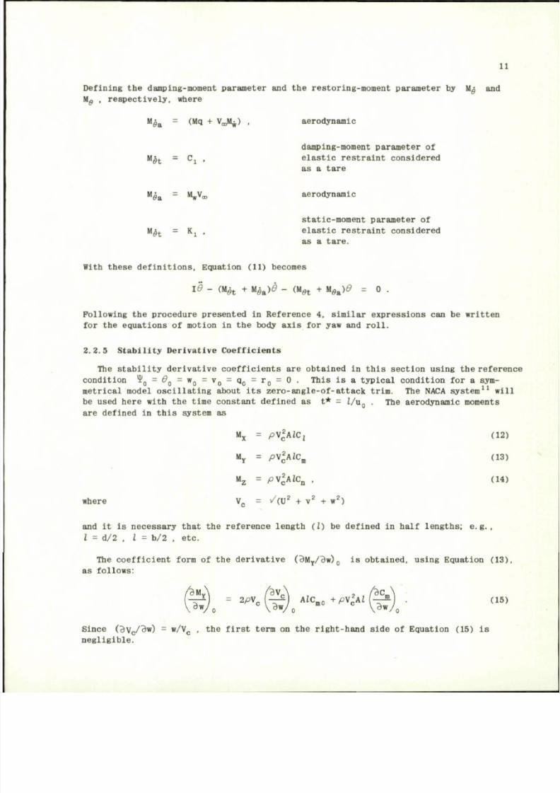
Defining th e damping-moment pa ram ete r and th e res tor in g-m om ent para m ete r by Mg and
Wg , r es pe c t iv e l y , where
aerodynamic
damping-moment parameter of
e l a s t i c r e s t r a i n t c o ns id e r e d
as a t a r e
aerodynamic
s ta t i c -moment parameter o f
e l a s t i c r e s t r a i n t c o n s id e r e d
as a t a r e .
With the se d e f i n i t io n s , Equat ion (11) becomes
id - m
h
+ m\
e&
)d - ( M
M
+ m\
ea
)d = 0 .
Following
the
procedure presented
in
Reference
4,
similar expressions
can be
written
for t he equations o f motion in the body axis for ya w and roll.
2.2.5 Stability Derivat ive Coeff icients
The stability derivative coefficients
are
obtained
in
this section using the refere nce
condition
?
0
= d
Q
= w
Q
= v
0
= q
0
= r
Q
= 0
. This
is a
typical condition
for a
sym
metrical model oscillating about
its
zero-angle-of -attack trim.
T h e
NACA system
11
will
be used here with
t he
time constant defined
as t* = i/ u
0
. The
aerodynamic moments
are defined
in
this system
as
, 2
M
x
= pV
2
A*C
z
(12)
M
y
= p\
2
c
A lC
m
(13)
M
z
= p \
2
c
A lC
n
. (14)
where V
c
= / ( U
2
+ v
2
+ w
2
)
and it is necessary that the refere nce length ( I ) be defined in half lengths; e.g.,
I = d/2
,
I = b/2 , etc.
The coefficient form
of the
derivative
( BM
y
/Bw)
0
is
obtained, using Equation (13),
as follows:
Since (Bv
c
/Bw)
= w/V
c
, the
first term
on the
right-hand side
o f
Equation (15)
i s
negligible.
8/10/2019 Techniques for Measurement of Dynamic Stability Derivatives in Ground Test Facilities
http://slidepdf.com/reader/full/techniques-for-measurement-of-dynamic-stability-derivatives-in-ground-test 32/236
12
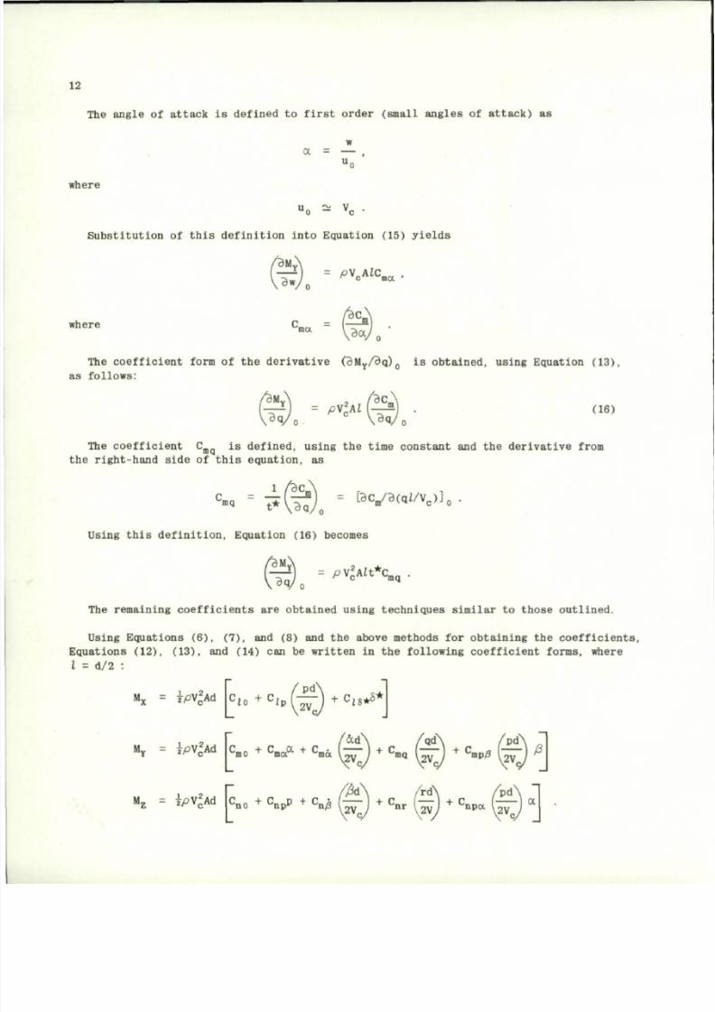
T he a n g l e o f a t t a c k i s d e f i n e d t o f i r s t o r d e r ( s m a l l a n g l e s o f a t t a c k ) a s
ot
where
u ^ V
o — "c
Substitution of this definition into Equation (15) yie lds
^BM'
^
:
'VIC. ,
where
J S .
Ba
The coefficient form of the derivative (BM
Y
/Bq) is obtained, using E quation (13),
as fo l lows:
©..-*-ft
(16)
T he c o e f f i c i e n t C i s d e f i n e d , u s i n g t h e t i m e c o n s t a n t a nd t h e d e r i v a t i v e f rom
t h e r i g h t - h a n d s i d e o f t h i s e q u a t i o n , a s
3
"«
=
t*(^)
=
l 9 V 3 ( q Z A
c
) ]
0
.
Using t h i s d e f in i t i o n , Equa t ion (16 ) becomes
^ M
v
,
= P ^
A l t
^
T he r e m a i n i n g c o e f f i c i e n t s a r e o b t a i n e d u s i n g t e c h n i q u e s s i m i l a r t o t h o s e o u t l i n e d .
Us ing Eq ua t io ns (6 ) , ( 7 ) , and (8 ) and th e above methods fo r ob ta in i ng the co e f f i c i en t s ,
Eq ua t ion s (12 ) , ( 13 ) , and (14 ) can be w r i t t en in t he fo l lowing c oe f f i c i en t f o rms , where
I = d /2 :
M
x
= |
P
V
2
A d C ,
0
+
C / P
S )
+ C
8
*
S
*
['
A d |c
m0
+ C.JX + c
mo
v
ina
ma
v2V„
+ c
mq
^2V„
+ C,
M
z
=
j p V
2
A d
C
n 0
+
C
n p
p
+ C
n /
g ( - - 1 + B L - ( -
9
\
2 V
9
\2Vm
>2V,
n p a
v2V„
a
8/10/2019 Techniques for Measurement of Dynamic Stability Derivatives in Ground Test Facilities
http://slidepdf.com/reader/full/techniques-for-measurement-of-dynamic-stability-derivatives-in-ground-test 33/236
13
S E C T I O N 3
C A P T I VE M O D E L T E S T I N G T E C H N I Q U E
3.1 G E N E R A L D E S C RI P T I O N
O F
T E C H N I Q U E
Methods for obtaining rotary deriv ative s in pitch, yaw or roll involve restraint of
the model
in
several degrees
o f
freedom
and
measurement
of
mome nts required
to
sustain
an oscillation
for
specified conditions
o f
frequency
and
amplitude (forced o scillation
technique)
or
measurement
of
model motion after
it has
been disturbed (free oscilla tion
technique).
The basic units
in the
captive model testing system
are the
pivots,
the
support
system and,
in the
forced oscilla tion t echnique, mecha nisms
for
forcing
the
model
oscillation. T h e pivot is a very important part o f a dynamic stability test system,
and
the
selection
of the
type
o f
pivot
and
desi gn will depend
on
several fac tors, some
of which have
a
direct bearing
on the
quality
of
data that
may be
obtained with
t h e
system. Also o f importa nce is the suspe nsion system and the influence it may have on
the aerodynamic measurements. Detailed descriptions
o f
model pivots, suspension systems,
and balance tare damping characteristics
are
presented
in
Sec tions 3.1.
1 to
3.1.3.
3. 1. 1 Model Piv ots
Pivots
of
various types which
are
employed
in
dynamic stability balances include
ball bearings,
g a s
bearings, knife edges, cones,
and
crossed flexures.
The
selection
of a particul ar type pivot will dep end on the system operating requirements and the
environment
in
which
it
will
be
used.
One of the
most important factors that must
be
considered
in the
design
of a
dynamic s tability balance
for
aerodynamic damping measur e
ments
is the
damping that
the
system contribute s
to the
meas ured wind
on
damping.
Aerodynamic damping decreases with increased Mach number
and
becomes
a
small per centage
of the measured damping at the hypers onic Mach numbers. O ne exception that will be
discussed
in
Section
3,1.3 are g as
beari ngs which generally have negligibl e tare
damping. Because
o f i ts
importance, ta re damping will us ually
be one of the
principal
considerations
for
selection
of the
pivot type
o r
bearing
for
roll damping balance
systems.
3.1.1.1 F l ex u r e
High pivot friction
may be
avoided
by
employing crossed flexures
o f th e
general
type shown
in
Figure
4.
These bend
in
such
a way
that
the
center
of
rotation remai ns
at essentially a fixed position. T h e crossed flexure provides stiffness, which is
necessary
to
overcome static moments
o n
models tested
at
angles
o f
attack
by the
free-
oscillation technique. Flexure piv ots
are
used
in
many applica tions,
in
particular
scientific instruments, because they have many favorable characteristics. They
a r e
simple
in
desig n,
yet
rugged
in
constructio n
for
their flexibility; they
do not
8/10/2019 Techniques for Measurement of Dynamic Stability Derivatives in Ground Test Facilities
http://slidepdf.com/reader/full/techniques-for-measurement-of-dynamic-stability-derivatives-in-ground-test 34/236
14
introduce hysteresi s
o r
backlash
in the
system; they
do not
require lubrication;
and
they
are not
susceptible
to
wear. Their main disad vantage
is
that they
are not
suitable
for large angles o f rotation because of stres s considerati ons, especially under com
bined loadings.
The
design
of
flexure piv ots
for a
particular application requires
consideration
of the
model loads, mom ents,
and
oscill ation frequency
for
dynamical
similitude. Experience
at the
AEDC-VKF
h a s
shown that crossed flexures have linear
stiffness characteristics and structural damping that is repeatable even though the
flexure
is of
multipiece construction. This method
of
construction
is
desirable because
the flexures can be machines as a single unit and then cut into sect ions for the in
dividual flexures.
The
theory
for
design
of
symmetrical crossed-flexure piv ots
is
given in References 13 through 16.
Examples o f flexure piv ots, including cruciform and torsion tube pivot s, that have
been used
in
various applications
are
shown
in
Figure
5. For
each
o f
these,
t he
pivot
tare damping varies inversely with the frequency o f oscillat ion. Strain gage s mounted
to
o ne
member
of the
crossed flexure
are
employed
to
obtain
a
signal v oltage which
is
proportional
to the
angular dis placeme nt.
For some applications, such as tests in very small tunnels or low density tunnels
which have
a
small test core,
it may be
impractical
to
machine flexure pivots
of the
type shown in Figure 5. Th e AEDC-VKF h a s developed a small dynamic stability balance
using
a
commerc ially available instrument fl exure pivot
of the
type shown
in
Figure
6.
The characteristics o f this pi vot were found to be repeatable and linear. Angular
motion time histories
are
measure d with
an
angular transducer described
in
Section
3.2.2. 1.
3 .1 .1 .2 Kn ife Edge and Cone
Knife edge and cone p iv o ts of th e typ e shown in F ig ur es 7 and 8 have rec en t l y been
u s e d i n d yn am ic s t a b i l i t y b a l a n c e s y s t e m s b e c a u s e t h e y a r e n e a r l y f r i c t i o n l e s s .
T he p r i n c i p a l d i s a d v a n t a g e o f e i t h e r t h e k n i f e e d ge o r c on e p i v o t i s t h a t som e
method o f r e s t r a in t must be employed to ho ld the p iv o t s i n con t ac t and f ine ad jus tme n t s
a r e n e c e s s a r y t o e l i m i n a t e b i n d i n g .
The s ln g le - de gre e -o f - f r e edo m kn i f e edge p i vo t shown in F igu re 7 was used in a s i n g l e -
degree-of-
f reedom f r e e -o s c i l l a t i o n ba l a nce sys t em deve loped a t DTMB. Here kn i f e edges
a r e used to cons t r a in t he mode l and a l so fo rm the ax i s o f r o t a t i on .
A s i m i l a r t ec hn iq ue ha s a l so been used by DTMB fo r a t h r e e -d egr ee - o f - f r eed om ba la nce
system; however , i n th i s ca se , th e model mount ing system i s a cone on the end of t he
s t i n g i n s e r t e d i n a c o n i c a l d e p r e s s i o n c o n t a c t w i t h i n t h e m od el ( F i g . 8 ) . T he m od el
i s f r e e t o r o l l , p i t c h , and yaw abou t t he cone and i s he ld on th e p iv o t by mode l d r ag .
In each o f t hese cases , mode l a t t i t ude i s measu red f rom pho tograph ic r eco rds o f mode l
mot ion.
3 . 1 . 1 . 3 B a l l B e a r i n g
Ball bearing pivots may be used in a dynamic stabil ity balance system for pitch and
yaw derivative measurements if high resultant model loads are to be supported and if
aerodynamic damping
is
large
so
that bearing dampi ng constitut es
a
small part
of the
8/10/2019 Techniques for Measurement of Dynamic Stability Derivatives in Ground Test Facilities
http://slidepdf.com/reader/full/techniques-for-measurement-of-dynamic-stability-derivatives-in-ground-test 35/236
15
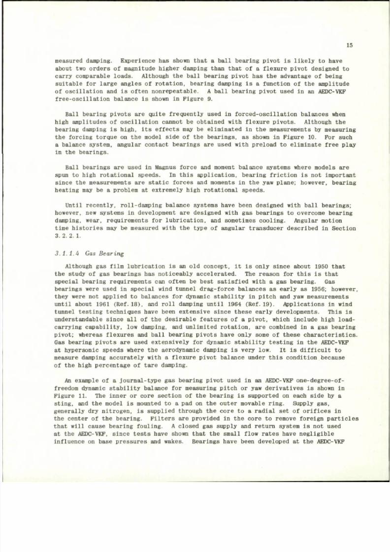
measured damping. Experience h a s shown that a ball bearing pi vot is likely to have
about two orders o f magnitude higher damping than that of a flexure pivot designed to
carry comparable loads. Although th e ball bearing pivot h a s t h e advantage o f being
suitable for large angles of rotation, bearing dam ping i s a function of the amplitude
of oscillation
and is
often nonrepeatable.
A
ball bearing pivot used
in an
AEDC-VKF
free-oscillation balance is shown in Figure 9.
Ball bearing pivots are quite fre quently used in forced-os cillation balances when
high amplitudes o f oscilla tion cannot b e obtained with flexure pivots. Although t h e
bearing damping is high, its effects may be eliminated in the measurements by measuring
the forcing torque on the model side of the bearings, a s shown in Fig ure 10. For such
a balance system, angular contact bearings are used with preloa d t o eliminate free play
in t he bearings.
Ball be arings are used in Magnus force and moment ba lance s ystems where mod els are
spun to high rotational speeds. In this application, b earing friction is not important
since
the
measurements
are
static forces
and
moments
in the yaw
plane; however, bearing
heating may be a problem at extremely high rotational speeds.
Until recently, roll-damping balance systems have been designed with ball bearings;
however, ne w systems in development are designed with g a s bearings to overc ome bearing
damping, wear, requirements for lubrication, and sometime s cooling. Angular motion
time histories may be measured with t he type o f angular transducer described in Section
3.2.2. 1.
3.1.1.4 Gas Be ar ing
Although g a s film lubrication is an old concept, it is only since about 1950 that
the study
o f g a s
bearings
h a s
noticeably accelerated.
T h e
reason
for
this
is
that
special bearing requirements can often be best satisfied with a g a s bearing. G a s
bearings were used in special wind tunnel drag-fo rce balances a s early as 1956; howe ver ,
they were no t applied to balances for dynamic stability in pitch and yaw measurements
until about 1961 (Ref.
1 8 ) ,
and roll dampi ng until 1964 (Ref.
1 9 ) .
Applications in wind
tunnel testing techniques have been extensive since these early developments. This is
understandable since all of the desirable features o f a pivo t, which include high load-
carrying capability, low damping, and unlimited rotation, a re combined in a gas bearing
pivot; whereas flexures and ball be aring pivot s have only some o f these characteristics.
Gas bearing pivots are used extensively for dynamic stability testing in the AEDC-VKF
at hypersonic speeds where th e aerodynamic damping i s very low. It is difficult to
measure damping accurately with a flexure pivot ba lance under this condition becaus e
of
the
high percentage
o f
tare damping.
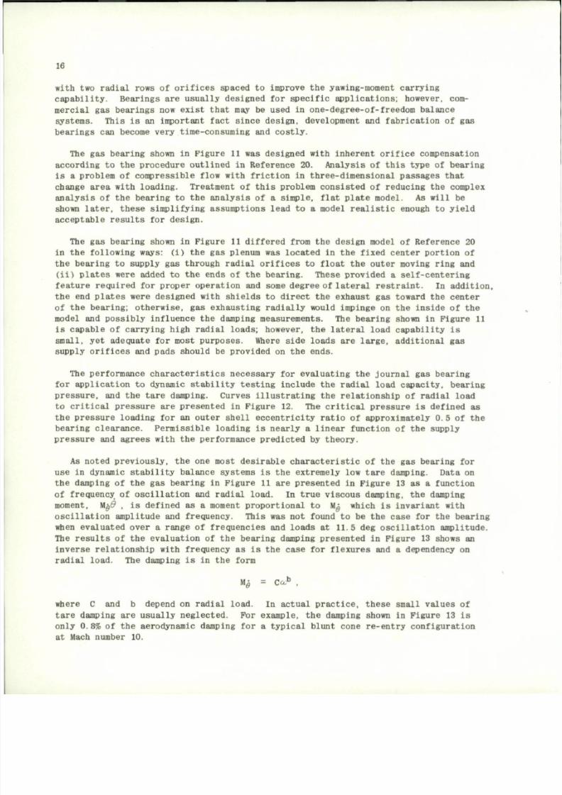
An example o f a journal-typ e g a s bearing pivot used in an AEDC-VKF one-degree-of-
freedom dynamic stability balance for measuring pitch o r y a w derivatives is shown in
Figure 11. Th e inner o r core section o f t h e bearing is supported on each s ide by a
sting, and the model is mounted to a pad on the outer movable ring. Supply g a s ,
generally dry nitrogen, is supplied through th e core to a radial set of orifices in
the center o f t he bearing. Filter s are provided in th e core to remove foreign particles
that will cause bearing fouling. A closed g a s supply and retur n system is not used
at th e AEDC-VKF, since test s have shown that t h e small flow rates have negligible
influence on base pressur es and wakes. Bearings have been developed at the AEDC-VKP
8/10/2019 Techniques for Measurement of Dynamic Stability Derivatives in Ground Test Facilities
http://slidepdf.com/reader/full/techniques-for-measurement-of-dynamic-stability-derivatives-in-ground-test 36/236
16
with two radial rows o f orifices spaced to improve t h e yawing-moment carrying
capability. Bearings
are
usually designed
for
specific applications; however, com
mercial gas bearings now exist that may be used in one-degree-of-freedom balance
systems.
This
is an
important fact since design, development
and
fabrication
of gas
bearings
can
become v ery time-c onsuming
and
costly.
The gas bearing shown in Figure 11 was designed with inherent orifice compensation
according
to the
procedure outlined
in
Refere nce 20. Analysi s
o f
this type
o f
bearing
is a problem of compres sible flow with friction in three-dimensional passages that
change area with loading. Treatm ent
of
this problem consisted
of
reducing
the
complex
analysis o f t h e bearing to the analysi s o f a simple, flat plate model. A s will be
shown later, these simplifying assumptions lead
to a
model realistic enough
to
yield
acceptable results for design.
The
ga s
bearing shown
in
Figure
11
differed from
the
design model
o f
Reference
20
in t he follo wing ways: ( i) the gas plenum wa s located in the fixed center port ion of
the bearing
to
supply
gas
through radial orific es
to
float
t he
outer moving ring
and
(ii) plat es were added t o t h e ends o f t h e bearing. These provided a self-centering
feature required
for
proper operation
and
some degree
of
lateral restraint.
In
addition,
the end plat es were designed with shields t o direct the exhaust gas toward the center
of
the
bearing; other wise,
gas
exhausting ra dially would impinge
o n the
inside
of the
model
and
possib ly influence
the
damping measur ements.
The
beari ng shown
in
Figure
11
is capable o f carrying high radial lo ads; however, the lateral load cap ability i s
small, y et
adequate
for
most purposes. Where side loads
are
large, additional
gas
supply orifices and pads should be provided on the
ends.
The performance characteristics necessary for evaluating th e journal g as bearing
for application
to
dynamic sta bility te sting include
the
radial load capa city, bearing
pressure,
and the
tare damping. Cur ves illustrating
the
relationship
of
radial load
to critical pressure
are
presented
in
Fig ure 12.
T h e
critical pressure
is
defined
a s
the pressure loading for an outer shell eccentricity r atio o f approximately 0.5 of the
bearing clearance. Perm issi ble loading
is
nearly
a
linear function
of the
supply
pressure
and
agrees with
the
performa nce predicted
by
theory.
As noted previ ously, the one most desirable characteristic of the gas bearing for
use
in
dynamic stability balance sys tems
is the
extremely
low
tare damping. Dat a
on
the damping of the gas bearing in Figure 11 ar e presented in Figure 13 as a function
of frequency
of
oscillation
and
radial load.
In
true viscous damping,
the
damping
moment, M
0
d , is defined as a moment pr oportio nal to Mg which i s invariant with
oscillation amplitude
and
frequency. This
was not
found
to be the
case
for the
bearing
when evaluated over
a
range
o f
frequencies
and
loads
at 11.5 de g
oscillat ion amplitu de.
The results
of the
evaluation
o f t h e
bearing damping pre sented
in
Figure
13
shows
an
inverse relationship with frequency as is the case for flexures and a dependency on
radial load.
T he
damping
is in the
form
Mg =
Cc o
b
,
w h ere C a nd b d e pe n d o n r a d i a l l o a d . I n a c t u a l p r a c t i c e , t h e s e s m a l l v a l u e s o f
ta r e damping ar e us ua l ly ne gl ec te d . For example , th e damping shown in F ig ure 13 i s
on ly 0 . 8% of t h e ae rodynamic damping fo r a t y p i ca l b lun t cone r e - e n t ry co nf i gu ra t ion
at Mach number 10.
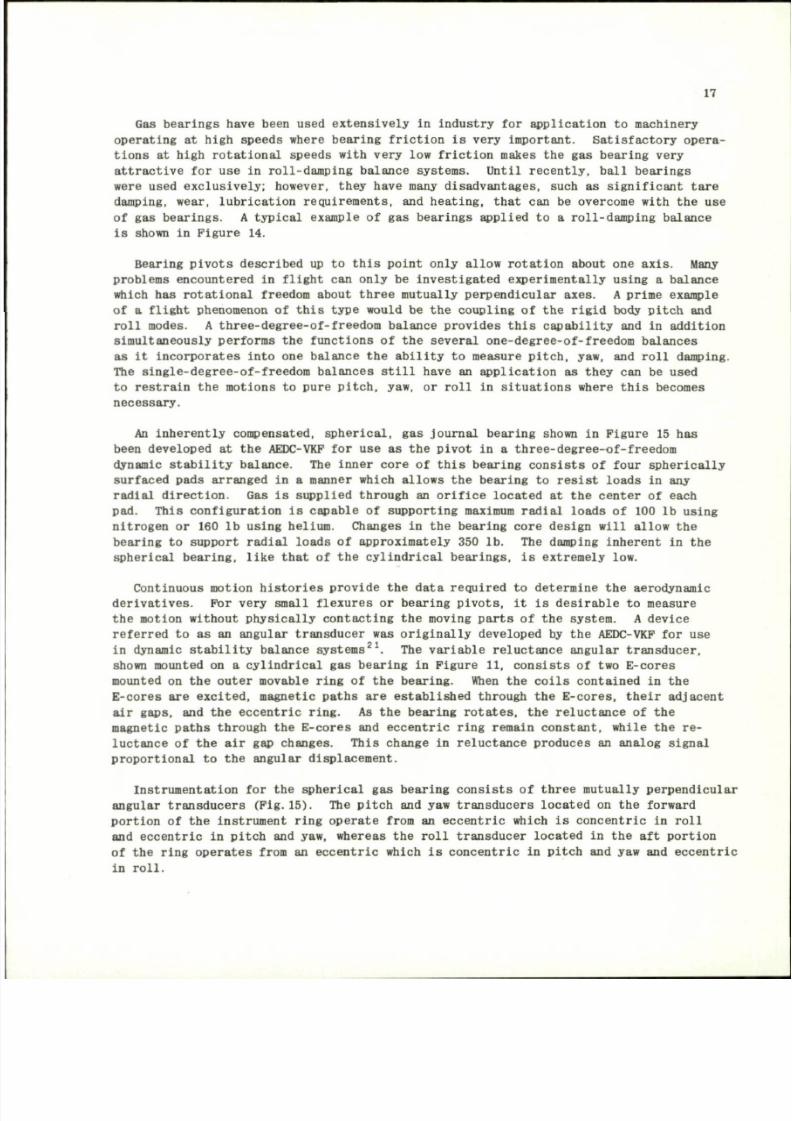
8/10/2019 Techniques for Measurement of Dynamic Stability Derivatives in Ground Test Facilities
http://slidepdf.com/reader/full/techniques-for-measurement-of-dynamic-stability-derivatives-in-ground-test 37/236
17
Gas beari ngs have been used extensively in industry for appl ication to machinery
operating at high spee ds where bearing friction is very important. Satisfa ctory opera
tions at high rotational speeds with very low friction makes the gas bearing very
attractive for use in roll-damp ing balance systems. Until recently, ball bear ings
were used exclusively; however, they have many disadvantages, such as significant tare
damping, wear, lubrication requirements, and heating, that can be overcome with the use
of gas bearings. A typical example of gas bearings applied to a roll-da mping balance
is shown in Figu re 14.
Bearing pivots described up to this point only allow rotation about one axis. Many
problems encountered in flight can only be investigated experimentally using a balance
which has rotational freedom about t hree mutually perpendicular axes. A prime example
of a flight phenomenon of this type would be the coupling of the rigid body pitch and
roll modes. A three-degree-of-freedom balance provide s this capability and in addition
simultaneously perfo rms the functions of the several one-degree-of-freedom balances
as it incorporates into one balance the ability to measure pitch, yaw, and roll damping.
The single-degree-of-freedom balances still have an application as they can be used
to restrain the motions to pure pitch, yaw, or roll in situations where this becomes
necessary.
An inherently compensated, spheri cal, gas journal bearing shown in Figur e 15 has
been developed at the AEDC-VKF for use as the pivot in a three-degree-of-freedom
dynamic stabilit y balance. The inner core of this bearing consists of four spherically
surfaced pad s arranged in a manner which allows the bearing to resi st loads in any
radial direction. Gas is supplied through an orifice located at the center of each
pad. This configuration is capab le of supporting maximum radial l oads of 100 lb using
nitrogen or 160 lb using helium. Changes in the bearing core design will allow the
bearing to support radial loads of approximately 350 lb. The damping inherent in the
spherical bearing, like that of the cylindrical bearings, is extremely low.
Continuous motion histories provide the da ta required to determine the aerodynamic
derivatives. For very small flexures or bearing pivots, it is desirable to measure
the motion without physically contacting the moving parts of the system. A device
referred to as an angular transducer was originally developed by the AEDC-VKP for use
in dynamic stability balance s yst ems
2
. The variable reluctance angular transducer,
shown mounted on a cylindrical g as beari ng in Figure 11, consists of two E-c ores
mounted on the outer movabl e ring of the bearing. When the coils contained in the
E-cores are excited, magnetic paths are established through the E-cores, their adjacent
air gaps, and the eccentric ring. As the bearing rotat es, the reluc tance of the
magnetic path s through the E-core s and eccentric ring remain constant, while the re
luctance of the air gap changes. Thi s change in relucta nce pro duc es an analog signal
proportional to the angular displacement.
Instrumentation for the spherical ga s bearing consists of three mutuall y perpe ndicular
angular transducers
(Pig.15).
The pit ch and ya w transducer s located on the forward
portion of the instrument ring operate from an eccentric which is concentric in roll
and ecce ntric in pitc h and yaw, whereas the roll transducer located in the aft portio n
of the ring oper ates from an eccentric which is concentric in pitch and yaw and e ccentric
in roll.
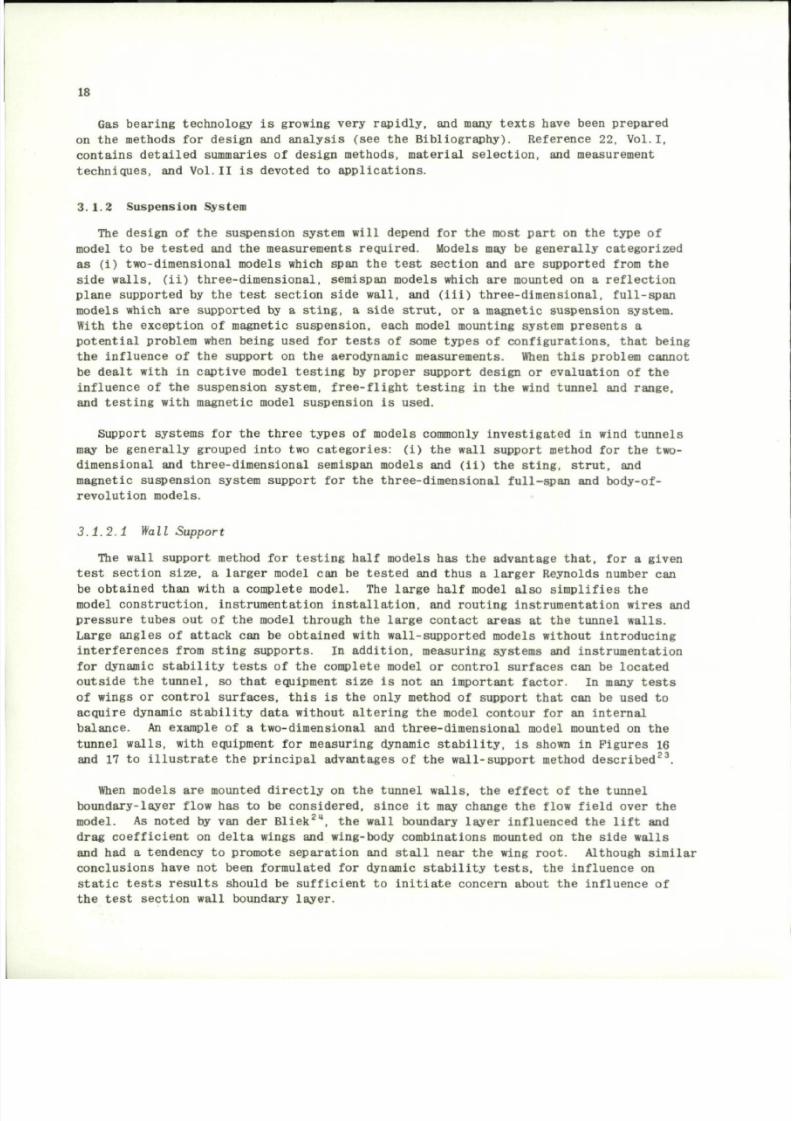
8/10/2019 Techniques for Measurement of Dynamic Stability Derivatives in Ground Test Facilities
http://slidepdf.com/reader/full/techniques-for-measurement-of-dynamic-stability-derivatives-in-ground-test 38/236
18
Gas bearing technology is growing very rapidly, and many texts have been prepared
on
the
methods
for
design
and
analysis
(see the
Bibliography). Refer ence 22, Vol.1,
contains detailed summaries o f design methods, material selection, and measurement
techniques,
and
Vol.II
is
devoted
to
applications.
3.1.2 Sus pensio n Syste m
The de sig n of th e susp ens ion sys tem wi l l depend for the most p a r t on th e type of
mode l t o be t e s t e d and the measuremen t s r eq u i r ed . Mode ls may be ge ne ra l ly ca t eg or i ze d
as (1 ) two-d imens iona l mode l s wh ich span the t e s t sec t ion and a r e suppor t ed f rom the
s i d e w a l l s , ( i i ) t h r e e - d i m e n s i o n a l , s e m is p an m o de ls w hic h a r e m o un te d o n a r e f l e c t i o n
p l a n e s u p p o rt e d by t h e t e s t s e c t i o n s i d e w a l l , a nd ( i i i ) t h r e e - d i m e n s i o n a l , f u l l - s p a n
mode l s wh ich a r e supp or t ed by a s t i n g , a s id e s t r u t , o r a magn e t i c susp ens io n sys t em.
Wi th th e exc ep t ion o f magne t i c susp ens ion , each mode l moun t ing syst em p r es en t s a
p o t e n t i a l p r ob l em when b e i n g u s ed f o r t e s t s o f s om e t y p e s of c o n f i g u r a t i o n s , t h a t b e i n g
th e in f lu en ce o f t he sup por t on th e ae rodynamic measuremen t s . When th i s p rob lem canno t
b e d e a l t w i t h i n c a p t i v e mo de l t e s t i n g b y p r o p e r s u p p o r t d e s i g n o r e v a l u a t i o n o f t h e
i n f l u e n c e o f t h e s u s p e n s i o n s y st e m , f r e e - f l i g h t t e s t i n g i n t h e win d t u n n e l an d r a n g e ,
and t e s t i n g wi th magne t i c mode l susp ens io n i s u sed .
Suppor t sys t em s fo r t he t h r e e t yp es o f mode l s commonly in ve s t ig a t ed in wind tun ne l s
may be ge ne ra l ly g rouped in to two ca t e go r i e s : ( i ) t he wa l l suppo r t method fo r t he two-
d i m e n s i o n a l a nd t h r e e - d i m e n s i o n a l s e m is p a n m o d e ls a nd ( i i ) t h e s t i n g , s t r u t , a nd
m a g n e t i c s u s p e n s i o n s y s te m s u p p o r t f o r t h e t h r e e - d i m e n s i o n a l f u l l - s p a n a nd
body-of-
r e v o l u t i o n m o d e l s .
3 . 1 . 2 . 1 W all S u p p o r t
The wa l l sup por t me thod fo r t e s t i n g ha l f mode l s has t h e advan tage tha t , f o r a g iven
t e s t s ec t io n s i z e , a l a rg e r model can be t e s t ed and thu s a l a rg e r Reyno lds number can
be ob ta in ed than wi th a comple t e mode l. The l a rg e ha l f model a l s o s im p l i f i e s t h e
m od el c o n s t r u c t i o n , i n s t r u m e n t a t i o n i n s t a l l a t i o n , a nd r o u t i n g i n s t r u m e n t a t i o n w i r e s and
p r e s s u r e t u b e s o u t of t h e m od el t h r o u g h t h e l a r g e c o n t a c t a r e a s a t t h e t u n n e l w a l l s .
L a r g e a n g l e s of a t t a c k c a n b e o b t a i n e d w i th w a l l - s u p p o r t e d m o d e ls w i t h o u t i n t r o d u c i n g
i n t e r f e r e n c e s from s t i n g s u p p o r t s . I n a d d i t i o n , m e a s u r in g s y s t e m s a nd i n s t r u m e n t a t i o n
f o r d yn am ic s t a b i l i t y t e s t s o f t h e c o m p l e t e m od el o r c o n t r o l s u r f a c e s c a n b e l o c a t e d
o u t s i d e t h e t u n n e l , s o t h a t e q ui pm e n t s i z e i s n o t a n i m p o r t a n t f a c t o r . I n m any t e s t s
o f wings o r con t ro l s u r f ac es , t h i s i s t he on ly method o f suppo r t t h a t can be used to
a c q u i r e dy na m ic s t a b i l i t y d a t a w i t h o u t a l t e r i n g t h e m od el c o n t o u r f o r an i n t e r n a l
ba l a nce . An example o f a two-d imen s iona l and th r ee -d im en s io na l mode l mounted on th e
tun ne l w a l l s , w i th equ ipmen t f o r measu r ing dynamic s t a b i l i t y , i s shown in F ig ure s 16
and 17 t o i l l u s t r a t e t h e p r i n c i p a l a d v a n t a g e s o f t h e w a l l - s u p p o r t me th od d e s c r i b e d
2 3
.
When mode l s a r e moun ted d i r e c t l y on the t un ne l wa l l s , t h e e f f e c t o f t h e t u nn e l
bou nda ry - l a ye r f l ow has t o be con s ide r ed , s in ce i t may change the f l ow f i e ld o ver t h e
model . As note d by van der Bl ie k
2 4
, t he wa l l boundary l ay e r i n f lue nce d the l i f t and
drag co e f f i c i en t on d e l t a wings and wing-body com bina t ion s mounted on the s ide wa l l s
and had a t endenc y to p romote se pa ra t io n and s t a l l nea r t h e wing ro o t . Al though s im i l a r
c o n c l u s i o n s h av e n o t be en f o r m u l a t e d f o r dy na m ic s t a b i l i t y t e s t s , t h e i n f l u e n c e on
s t a t i c t e s t s r e s u l t s sh o u ld b e s u f f i c i e n t t o i n i t i a t e c o n ce r n a b o ut t h e i n f l u e n c e o f
t h e t e s t s e c t i o n w a l l b o u nd a ry l a y e r .
8/10/2019 Techniques for Measurement of Dynamic Stability Derivatives in Ground Test Facilities
http://slidepdf.com/reader/full/techniques-for-measurement-of-dynamic-stability-derivatives-in-ground-test 39/236
19
In order t o alleviate the influence o f the'wall boundary layer, several m etho ds
have been used with success
at
subsonic speeds
by
vario us investigators. These include
boundary-layer removal through porous walls o r slots ahead o f t h e model and th e in
stallation o f V-shaped vortex generators on the tunnel wall ahead o f t h e attachment.
Formation
o f
large disturbed areas
o n the
model close
t o t h e
wall
may be
prevented
by
using fences attached to the model o r displacing t h e model from th e tunnel wall by
inserting shims between the model and walls. Each of these meth ods h a s t h e disadvantage
of altering t h e shape o f t h e model configuration and not completely eliminating t h e
influence o f th e wall bo undary layer.
Tests have shown that wall boundary-layer effects are largely eliminated by using
reflection planes o f th e types illustrated in Figure 18. With this method, a reflection
plane is introduced a s t h e longitudinal plane o f symmetry and is displaced from t h e
wall to allow passage of the wall bo undary layer flow. Fo r some mounting method s,
contouring in the flow pa ssage may be necessar y to eliminate choking o f t h e flow and
the resultant ineffectiveness o f t h e reflection plane. T h e reflection plane can be
fixed
to the
wall
and the
model rotated,
o r t h e
model
can be
fixed
to the
plate
and
rotated as a unit. When t he model i s rotated on the reflection plate , as is generally
done in dynamic stability tests, a gap must be allowed, which ma y introduce leakage
around the model reflection-plane junction and change the local flow field. Tests o f
very blunt models on reflection planes will produce significant boundary-layer separa
tions and thus alter th e mode l flow field. Informa tion on reflection pla ne design i s
given in Reference 26.
3 . 1 . 2 . 2 S t i n g S u p p o r t
Sting supports are principally used in tests o f complete ve hicle configur ations and
are inserted into t h e model base through t he center o f t h e wake to minimize their in
fluence
o n the
model flow field. Careful attention must
be
given
to the
design
of
the sting to insure that it provides a stiff support; however, modifica tion o f t h e
model contour may be necessary to accommodate the sting. Such a modification is a
compromise between a small diameter sting o f constant length for a distance behind
the model and one which will ca rry th e aerodynamic loads without significant movement
of the pivot axis. Often t he consequences o f t h e compromise are not clear, and there
fore tests are required to evaluate t h e influence.
Static tests
27
have shown that both th e sting diameter and sting length hav e an
influence on force and base pressure data for most configurations. Some forced-
oscillation systems have shaker motors in enlarged sections o f t he sting support, to
simplify t he overall design and reduce the complexity o f t h e driving linkages. In
these cases it is important that t he enlarged section be located an ample distance
downstream o f t h e model base to permit proper formation o f t h e wake. Very few experi
ments have been conducted to investigate specifically t h e influence o f th e sting
diameter and length o n dynamic stabilit y measureme nts.
A series o f tests have been conducted at the AEDC-VKP (Ref.28), over a range o f
Reynolds numbers, to investigate the influence o f t he sting diameter and length o n
the dynamic stability o f a 10-deg half-angle cone with a flat
base.
To determine t h e
relative effects o f sting length, distu rbances downstream o f t h e model base were
introduced by placing a 20-deg conical windshield at vario us stations along the sting
from
0.75d
to 3d. Relati ve interference caused by the sting diameter size wa s created
8/10/2019 Techniques for Measurement of Dynamic Stability Derivatives in Ground Test Facilities
http://slidepdf.com/reader/full/techniques-for-measurement-of-dynamic-stability-derivatives-in-ground-test 40/236
20
by repeating
t he
tests with diameters
o f
0.4,
0.6, and
0.8d.
The
test result s i ncluded
dynamic stability, static stability,
and
base pressure data, since base pressure s
are
very sensitive to the degree of Interference t hat t h e support presents to the base
flow.
Representative results
are
shown
in
Fig ure s 19,
20, 21, and 22 for
Mach numbers
2.5,
3, and 4
over
a
range
o f
Reynolds numbers
and
sting l engths using thr ee sting
diameters.
Evidence
of
interference caused
by the
support length
may be
judged
by the
deviation of the base pressure ratio from the reference curve corresponding to the
longest sting length
(i
s
/d =
3).
Boundary-layer transition
is
generally
at the
model base,
at a
Reynolds number which
is slightly less than the value where t he minimum base pressur e occurs. An analysis
of
the
results based
on the
base pressure data
and
schlieren photo graphs
f or L / d = 3
shows that the Reynold s number range wa s sufficient for a transitional and fully turbulent
wake. There
i s
evidence
in the
data presented
in
Figure
19 to
confirm that some support
geometry configurations can have an influence on the dynamic stability derivatives.
However, it
appears that
if the
support
is
designed usi ng crit eria
f or
static force
and base pressure
t e s t s
27
,
it is
unlikely that
the
dynamic stability data will
be in
fluenced. This observation does
no t
apply
to
configur atio ns which have contoured bases,
since these
are
more critical with regard
to the
Influence
of the
support because
t h e
wake condition h a s a direct influence on the pres sure distribu tion around the base. A
further complication ar ises
in
this case because
the
base must
be
partially removed
to
allow movement of the model over the sting. In cases where the relative influence o f
the support system
on
damping resu lts cannot
be
assessed
by
capti ve model testing, wind-
tunnel, free-flight, and aeroballistic range tests are necessary to obtain compara tive
results.
Some examples
o f a
very rigid sting
and
support
for a
high frequency, free-os cillat ion,
dynamic stability balance system are shown in Figure 23 and a more conventional support
for
a l o w
frequency system
is
shown
in
Figure
24.
3 . 1 . 2 . 3 S t r u t S u p p o rt
Where limitations
o n
model amplitudes
are
imposed
by
mechanical interference between
the model base
and
sting, these
may be
overcome
by
mou nting
the
model
on a
transverse
rod support system
so
that
it is
free
to
rotate
on the rod
with
no
restraints.
An
example of one such system us ed in the AED C-VKF 50-in. M ach 10 tunnel is shown in Figure
25.
The balance, consisting o f a gas-bearing pivot, model lock, and position
trans
ducer, is
contained within
the
model; nitrogen
gas for the
bearing
and the
model posi
tion lock and instrumentation leads pas s through the transverse rods.
Extension
of the
transverse
rod
into
the
model will affect
the
flow over
the
model
primarily
in the
region
aft of the rod and
along
the
sides
of the
model.
A
region
of
flow separation will exist on the model ahead o f t h e rod. Since th e interference flow
field caused
by the rod
will depe nd
on the
boundary-laye r flow
and the
position
of the
interference on the model surface, it is to be expected that meas urements obtained with
a transverse
rod
support system will
be
dependent upon
t he
oscillation amplitude
and
the Rey nolds number
of the
flow.
An
example
o f
such
a
dependence
is
shown
in
Figure
26,
where data obtained with
a
sting support
are
included
for
comparison.
It is
apparent
from these results, for a 10-deg half-angle cone at Mach number 10, that both Reynolds
number
and
oscillation amplitude
are
important parameters.
It
should
be
noted t hat
when
the
Reynolds number
is
large
t he
influence
of
Reynolds number
and
amplitude
dis
appear
and the
resul ts obt ained with
a
sting support
and
transverse
rod
support
are
8/10/2019 Techniques for Measurement of Dynamic Stability Derivatives in Ground Test Facilities
http://slidepdf.com/reader/full/techniques-for-measurement-of-dynamic-stability-derivatives-in-ground-test 41/236
21
in agreement. Howeve r, at low Reynolds numbers, very large differences can exist in
results obtained by the two metho ds, t hus indicating significant adverse effect s from
the transverse rod.
The Influence
o f t h e
size
o f t h e
transverse
rod
supports
at
Mach
5 is
shown
in
Figure 27 for a blunt c one cylinder m odel with and without a base flare. A cylindrical
ro d and double-wedge rod were tested with roughness on the model nose to produce
turbulent flow and thus to eliminate separation ahead o f t h e base flare. The results
show no significant effects caused by rod size for diameters up to 30 % of the model
diameter and no effect s caused by rod configuration, i.e., a cylindrical rod as com
pared to a double- wedge rod. A significant reduction of the damping occurr ed when
roughness and the transverse rods were eliminated for the configuration with th e flared
base, because o f t h e r o d wake influence on the region o f separated flow ahead o f t h e
flare.
Although very fe w systematic investigations h ave been conducted to investigate t h e
effects
o f
transverse
rod
geometry
on
dynamic da mping ove r
a
range
of
model configura
tions,
Mach numbers, Reynolds numbers, and amplitudes, t h e data available tend to in
dicate that (i) rod influence becom es negligib le at the high Reynolds numbers when t h e
flow is turbulent and (ii) rod size effects are small pr ovided the rod is small com
pared to the model
size.
Tests with transverse rod support s should be supplemented
with te sts employing a sting support balance system to provide comparative data at
low amplitudes, where the influence o f t h e transverse rod is most pronounced.
3. 1 . 2 . 4 Magnet i c Model Suppor t
Magnetic suspension provides a means for suspending a model in a test unit without
any physical support, and thereby eliminates any questions about the experim ental
results being influenced
by the
method
o f
physical support (sting
or
strut).
T h e
magnetic suspension system consists o f a series o f electr omagnets which prod uce magnetic
fields and gradients o f magnetic fields to provide forces and moments o n a
model.
T h e
model h a s a mag netic moment which may be a part of the model if a permanent magnet i s
used in the model construction. Other metho ds for providing a magnetic moment are
described in Ref ere nce 29. Included in the system for control is an optical system
which monitors t h e position o f t h e model by light bea ms passing through t he test
section and focused onto sensors. When t h e system is in equilibrium, forces and
moments caused by gravity, aerodynamics, and inertial effects, for the case o f a moving
model, balance o u t t h e applied mag netic forces and moments. Changes in model position
activate th e control system, and curre nts flow through t h e magnetic coils to produce
forces and moments o n the model t o hold it in equilibrium.
A magnetic susp ension system with V-magnet o rientation d eveloped at the AEDC-VKF
(Ref. 30)
for static force, mom ent, and wake me asurem ents is shown in Figures 28 and
29.
A similar system, but with L orientation o f t h e magnets h a s been develo ped by
MIT (Ref. 31) to obtain static force, moment, and dynamic stability measurements.
3.1.3 Balance Tar e Damp ing
3 . 1 . 3 . 1 D e s c r i p t i o n o f D ampin g
Wind tunnel m odel s have to be mechanically suspended on a bearing o r spring to
pro
vide oscillatory motion. Exceptions to this are recent develo pments o f magnetic model
8/10/2019 Techniques for Measurement of Dynamic Stability Derivatives in Ground Test Facilities
http://slidepdf.com/reader/full/techniques-for-measurement-of-dynamic-stability-derivatives-in-ground-test 42/236
22
suspension systems which have been refined to the degree that damping data have been
obtained
29
. Mechanical susp ension introduces damping which must be accounted for in
the analysis.
Aerodynamic damping as a rule cannot be measured directly with most balance systems,
since it is a part of the measure d total damping; theref ore it must be obtained in
directly as the difference between the total and tare damping. With gas bearing pivot s
this is generally not necessary , since they usually hav e a negligible amount of tare
damping. It is customa ry in writing the linear differe ntial equations expressing an
oscillatory motion to assume that the total damping, which is the aerodynamic plus tare
damping, is propo rtional to
0 .
Therefore the motion in pitch for a free oscillation
may be expressed by
I
¥
0 - (M
5a
+
U
h
) 0
- ( M
5a
+
W
e t
) 6
= 0 .
where the subscript a identifies the aerodynamic term and t identifies the tare
term.
The term tare damping is applied here to denote the operation of non-aerodynamic
influences which, by r esisting t he motion and absorbing energy from the system,, reduce
the amplitude of motion. A constant-amplitu de oscilla tion would continue to exist if
damping forces of vari ous kinds did not exist. Damping forc es arise from the mechanical
system damping, damping capacity of the materials used in the system, and air damping.
Although it is convenient to classify the contributing factors in this manner in dis
cussing tare damping as applied to dynamic stability testing, the mechanical system
damping and damping capacity of the materials are inseparable in the measurements and
constitute the term M^
t
. Air damping is important only insofar as determining the
magnitude of M^
t
from air-off tests.
Mechanical system damping involves distinguishable part s of the system and arises
from slip and other boundary shear eff ects at mating surfa ces, interfaces, or joints.
Energy dissipation here may occur as the result of dry sliding (Coulomb friction)
lubricated sliding (viscous forces ) or both.
The damping capacity of materials, or material damping, refers to the energy dis
sipation that occur s within the material when the structure is undergoing cyclic stress
or strain. These internal energy los ses may be considered as being due to imper
fections in the elastic properti es of the material. In a truly elastic member, not
only is strain proportional to stress but also, on removal of the stress, the material
retraces the stress-strain relationship that existed during the application of the
stress. Even if mate rial s are stressed within the elastic limit, some energy is lost.
Energy dissip ation in a material during a stress cycle leads to a hyste resis loop in
the stress-strain curve and the a rea of the loop denotes the energy lost per cycle.
Air damping resu lts from a loss of energy caused by restrictive effects as a mass
moves through a medium such as air. The damping may result from dynamic pressure,
vis cou s effects, and vort ex formation and shedding; however, the relative ef fects of
each are not known. Theore tical studies of the visc ous damping force on a sphere and
cylinder oscillating in a fluid
3 2 , 3 3
show that each will experience forces proportional
to the velocity and square root of the fluid density. Experimental air-damping data
for circular and rectangular plates, cylinders, and spheres are presented in Reference
34 and show the effect of pres sure , vibrator y a mplitude , frequency, shape, and surface
8/10/2019 Techniques for Measurement of Dynamic Stability Derivatives in Ground Test Facilities
http://slidepdf.com/reader/full/techniques-for-measurement-of-dynamic-stability-derivatives-in-ground-test 43/236
23
area on the air damping for models that a re mounted on the end of a cantilever beam.
The results show that air damping associated with plat es is directly proporti onal t o
the ambient pressure and amplitude i s indicative o f t h e influence o f dynamic press ure.
Low amplitude results for cylinders oriented p erpendicular to the plane o f oscillatory
motion
are in
agree ment with
a
theory
by
S t o k e s
33
and are
proportional
to the
square
root of the density but show no vari ati on with frequency.
It is preferable to design dynamic-stabi lity balance system s in such a way that t h e
tare damping is small compared t o t h e aerodynamic damping. F o r some classes o f models
at hypersonic and hyperveloci ty speeds, where t he aerodynamic damping is low, the tare
damping can approach, or even exceed, t h e aerodynamic damping. An example o f t h e
contribution o f t h e mechanical system and air damping relative to aerodynamic damping
is shown in Figu re 30. It is apparent from this example that, a s t h e Mach number Is
increased, extreme care must be taken to obtain me asure ments o f tare damping with a
high degree o f accuracy, so that t he difference constitute s an accurate measurement
of t he aerodynamic damping.
3 . 1 . 3 . 2 E v a l u a t i o n of S t i l l - A i r Dam ping
Mechanical and material damping can be determined by tests in still air at
atmos
pheric pressure; however, this can introduce large errors in some cases, since t h e
damping th us obtained includes air damping. To determine t h e magnitude of air damping,
tests are made in a chamber o f t h e type shown in Figure 31 to permit variation in the
ambient pr essure. Th e wind tunnel can also be used for this test; however, i t s
environment must be free o f even sma ll amou nts o f airflow and turbulence. A typical
set of tare dam ping meas urements for a blunt cone model are shown in Figure 32 for a
range of pressure s from atmosphere to vacuum. T he level o f damping at a vacuum re
presents the mechanical system and material damping, since the air damping is essen
tially zero.
An
example
o f th e
magnitude
of the air
damping
a s a
percentage
o f t h e
aerodynamic damping is shown in Figure 33 for a series o f model shapes. At supersonic
speeds the air damping is on the order of 2 to 4%, but increases significantly with
Mach number, even approaching 100% o f t h e aerodynamic damping at Mach 10.
The necessity for accurate tare da mping resu lts h a s been mentioned and specific
reference made t o some o f t h e sources o f damping in a mechanical system, o ne being
energy dissipation in joints o f multiple piece systems. To ensure that t are damping
is repeatable and co nsistent, a number o f tare damping re cordings are usually made
following removal and replacement of the model and flexure o r pivot system until tare
damping is shown to be repeatable.
In cases where
t h e
axial and/or normal forces
are
large, measurements
are
made with
the pivot loaded to determine i t s influence on the mechanical damping and pivot
stiffness. In most cases the pivot static loading will have little effect on the tare
damping characteristics.
Since th e model undergoing test will oscillate at a frequency different from that
of th e tare damping tests at a wind-off condition, it is necessary to establish how
the energy loss o r tare, M g
t
, at a vacuum , will va ry with frequency. Fo r flexure-
type pivots Smi th
35
notes that the tare damping p e r cycle is a constant fraction of
the energy stored in the spring at the be ginning o f t h e cyc le, independent o f t h e
frequency. This is equivalent t o M ^
t
=
C/co ,
which wa s found earlier in experiments
by Welsh and Ward
36
.
8/10/2019 Techniques for Measurement of Dynamic Stability Derivatives in Ground Test Facilities
http://slidepdf.com/reader/full/techniques-for-measurement-of-dynamic-stability-derivatives-in-ground-test 44/236
24
3 . 1 . 3 . 3 D am pin g C h a r a c t e r i s t i c s o f D i f f e r e n t M e t a l s
Damping characteristics
of
mater ials exposed
to
cyclic stress
are
affected
by
several
factors, which must
be
considere d
in th e
selection
o f
materials
for
flexure pivo ts.
Some
of the
factors
are
(1) condition
of the
material
-
composition
and
effect
o f
heat treatment,
(ii) state
o f
internal s tress
-
effect
o f
machi ning
and
changes
in
stress
due to
cyclic motion
and
temperature h istories,
(iii) stress Imposed
by
service conditions
-
type
o f
stress, magnitude, stress
variations, and environmental conditions.
Factors which include
the
magnitude
of the
stress, stre ss history,
and
frequency
may
be si gnificant at one operati ng condition and unimportant at another. Final selection
of
a
material should
be
based
on
tests
o f a
specimen
in th e
configurat ion
in
which
the
material will
b e
used
and
under si mulated operat ing conditions.
It should
be
recognized that,
in
most systems where oscillations
o r
vibrations
occur, the damping introduced by the properties of the materials employed is, in general,
only one factor contributing to the total damping. Nevertheless, a knowledge of the
characteristics
of
structural material s
is
important
and the
choice
o f
material should
be guided by its damping characteristics.
Materials having
a
Young's modu lus which ranged from
6.2 x 10
s
for
magnesium
to
28.5 x 10
6
lb/in.
2
f or Armco 17.4 stainless steel have been tested in the VKF to provide
material damping data
for use as a
guide
in
selecting materials
for
flexure-pivot
designs.
An
example
o f t h e
material damping results
for a
range
o f
frequencies
and
beam stiffnesses
is
shown
in
Figure 34. Additional information
on
material damping
may
be found
in
Reference
37.
3. 2 D Y N A M I C S T A BI L I T Y D E R IV A T IV E S - P I T C H O R Y A W
The basic methods
for
obtaining dynamic stability meas urements
are
well known, dat ing
back to early 1920 when Briti sh r ep ort s o n the subject began to appear. It was found
that aerodynamic pitch damping derivatives consisted of two parts, M and M
a
, and
experiments were devised
to
account
for
these terms separately. These experiments were
successful; however,
it was
concluded that
the
technique
was not
satisfactory
for de
ducing M
a
at high speeds (transonic) or high frequencies. Some mode s o f oscillation
such
as
short-period damping
can be
evaluated satisfactorily
if the sum of the
damping
derivatives,
for
example
(c +
C
m ( 3 t
) ,
is
known, even t houg h
the
separate val ues
of
C a nd C ^ a re unknown. Insta nces m ay exist at supersonic speeds in which the
application
of
test d ata
t o
calculations
m ay
require
the
damping derivatives
in
some
way other than
the
combined form; however,
the
general practice
h a s
been
to
measure
the derivatives in combi ned form. Wind tunnel techniques that are in most general u s e
at supersonic speeds and above can be summarized as the free-oscillation and forced-
oscillation methods.
The free-oscillation method is one of the earliest used and is considered to be th e
simplest from
the
vie wpoint
o f
equipment
and
instrumentation.
The
model, restrained
by
a
pivot,
is
deflected
to an
initial a mplitude
and
released,
and the
decaying motion
is observed.
8/10/2019 Techniques for Measurement of Dynamic Stability Derivatives in Ground Test Facilities
http://slidepdf.com/reader/full/techniques-for-measurement-of-dynamic-stability-derivatives-in-ground-test 45/236
25
W ith t h e f o r c ed - o s c i l l a t i o n t e ch n i q u e , a r e s t r a i n e d mo de l i s f o r ced t o p e rf o rm
s i mp l e h a rmo n i c mo t io n by mean s o f an o s c i l l a t o r , t r a n s m i t t i n g f o r c e s t h r o u g h a l i n k ag e
to a to rqu e member which i s r i g id ly c onnected to the model. Normal ly th e s t ru c tu ra l
damping of ba la nce sy s tems used a t sup er so nic and hyp er so nic speeds i s very low and
the to rq ue member s t i f fn es s i s a l so low . Thi s r e qu i r es th e sys tem to be ope ra ted a t
or near i t s r eso na nt f r equency . In ord er to ob ta i n da ta over a w ide f r equency rang e ,
t h e mod el moment o f i n e r t i a o r t h e s t i f f n e s s o f t h e s t r u c t u r a l r e s t r a i n t may b e v a r i ed .
An a l t e r n a t i v e me th od t h a t may b e u s ed f o r t e s t s o v e r a w id e r an g e o f o s c i l l a t i o n
f req ue ncie s i s r e fe r re d to as ine xo rab le forc in g ; and as th e name im pl ie s , t he model
i s d r i v en i n a co n t r o l l e d man ne r by r i g i d l i n k ag e .
M ost f o r c ed - o s c i l l a t i o n s y s tems emp lo y s p e c i a l i n s t r u m en t a t i o n t e ch n i q u es wh ich
u t i l i z e a f e ed back co n t r o l s y st em f o r co n t r o l l e d o s c i l l a t i o n o f t h e mod el when n e g a t i v e
d amp in g i s p r e s en t . I n ad d i t i o n , t h e s e co n t r o l s y st ems p r o v i d ed amp l i t u d e co n t r o l f o r
measur ing p o s i t i v e damping .
B oth f r e e - o s c i l l a t i o n and f o r c e d - o s c i l l a t i o n b a l a n c e s may b e f u r t h e r c a t e g o r i z e d a s
e i t h e r s ma l l - am p l i t u d e o r h i g h - a mp l i t u d e s y st ems . A s ma l l - amp l i t u d e b a l an ce meas u r e s
lo ca l va lu es of damping and p i t c h in g moment s lop e , s in ce the model o s c i l l a t e s a t
am pl i tudes of about one or two de gre es , and i s o f t en used to ob ta in da ta a t a ng les of
a t t a ck o t h e r t h an ze r o . The b a l an ce s t i f f n e s s o r r e s t o r i n g moment f o r l a r g e - am p l i t u d e
b a l an c es i s n o r ma l l y ze r o o r n ea r z e r o . F o r ce d - o s c i l l a t i o n s y s tems may b e o p e r a t ed a t
about ±15 de gre es , as compared to am pl i tu des which are on ly l i m i te d by the ba lan ce
s u p p o rt f o r f r e e - o s c i l l a t i o n b a l a n c e s .
Th e ma t h ema t i ca l t r e a t m en t o f s y s t ems w i t h f r ee - o r f o r c ed - o s c i l l a t i o n mo t io n may
be found in many t e x t s ; however , th e methods a re t r e a t e d in th e next s ec t io n for th e
sake of comple teness .
3 .2 .1 Theory
T he t h eo r y f o r l i n ea r an d n o n - l i n e a r o n e - d eg r ee - o f - f r eed o m and t h r e e - d eg r ee s - o f -
fre ed om f r e e - o s c i l l a t i o n s y st e m s w i l l be t r e a t e d . The f o r c e d - o s c i l l a t i o n t h e o r y w i l l
be developed , fo l lowed by a br i e f t r e a tm en t o f lo ca l and ef fe c t iv e v a lu es of damping
an d f i n a l l y t h e ae r o d y n ami c t r an s f e r eq u a t i o n s w i l l b e d ev e l o p ed .
3 . 2 . 1 . 1 F r ee O s c i l l a t i o n ( O n e- D eg ree -O f -F r eed om)
The eq ua t ion of motion for a body in pi tc h was de r iv ed in Se ct io n 2. 2 and has th e
same ge ne ral form as th e equ at i on s of motion for a body in yaw and r o l l . For f re e-
o s c i l l a t i o n s y s tems h av i n g s t r u c t u r a l s t i f f n e s s , t h e eq u a t i o n o f mo t io n h a s t h e fo rm
1,0 - (M
0a
+ \A
e t
)0 - (M
ea
+ H
B t
)9 = 0 . (17)
After introducing ne w nomenclature for simplification o f t h e derivation o f t h e solution
to Equation (17), it becomes
l
y
d + c d + K d = 0 . (18)
8/10/2019 Techniques for Measurement of Dynamic Stability Derivatives in Ground Test Facilities
http://slidepdf.com/reader/full/techniques-for-measurement-of-dynamic-stability-derivatives-in-ground-test 46/236
26
T he g e n e r a l s o l u t i o n o f t h i s e q u a t i o n d e s c r i b i n g f r e e - o s c i l l a t i o n m o ti on c an b e
w r i t t e n a s
6
r t r t
Aj6 + A
2
e
(1 9 )
where Aj and A
2
a r e a r b i t r a r y c o n s t a n t s and v
1
and r
2
a r e t he ro o t s o f t he
c h a r a c t e r i s t i c s e q u a t i o n . T h es e a r e o b t a i n e d a s
21,
' C
2r[
(20)
bu t , s i n ce the undamped na tu r a l c i r c u l a r f r equency i s co = i / (K / I
y
) , a n d l e t t i n g
C / 2 I
y
= a , Equ atio n (20) becomes
r
1 > 2
= - a ± / ( a
2
- co
2
) .
The case o f Interest is a <
co ,
where the roots are complex, representing the condition
where th e system will oscillate. The general solution t o Equation (19) for this case
is
where
i.
2
d = A j e ^ " ) * + A ^ * " "
1
^ .
a ± bi
a - c/2I
v
(21)
b
=
f
C
c o ^ (undamped natural frequency)
Equation (21) ca n also b e written as
d
- ( C / 2 I
y
) t
&
0
e c o s (aj
d
± -cp)
(22)
d
Q
and cp
being arbitrary constants. Equation (22) represents
a
harmonic oscillation
with damping. When cos
(co^t
-
cp)
= 1 , the envelope encompassing the points of tangency
with the displacement
i s
described
by
d
=
d
0
e
( C / 2 I
y
) t
From thi s relationship, the logarithmic decrement
l o g
e
( 9 / 0
l
) i s
used
t o
obtain
t h e
damping term C . An often used parame ter for measuring the damping coefficient is
the time required
to
damp
t o a
particular amplitude ratio. Letting
d \ and 0
2
re
present a mplitudes occurring at times tj and t
2
, respectively, and letting
6*
2
/(9j = R , we obtain the following equation for the damping moment:
s i n c e
C = - 2 I
y
f l o g
e
R / C
y r
* 2
_
*l
c
yR
f
•
(23)
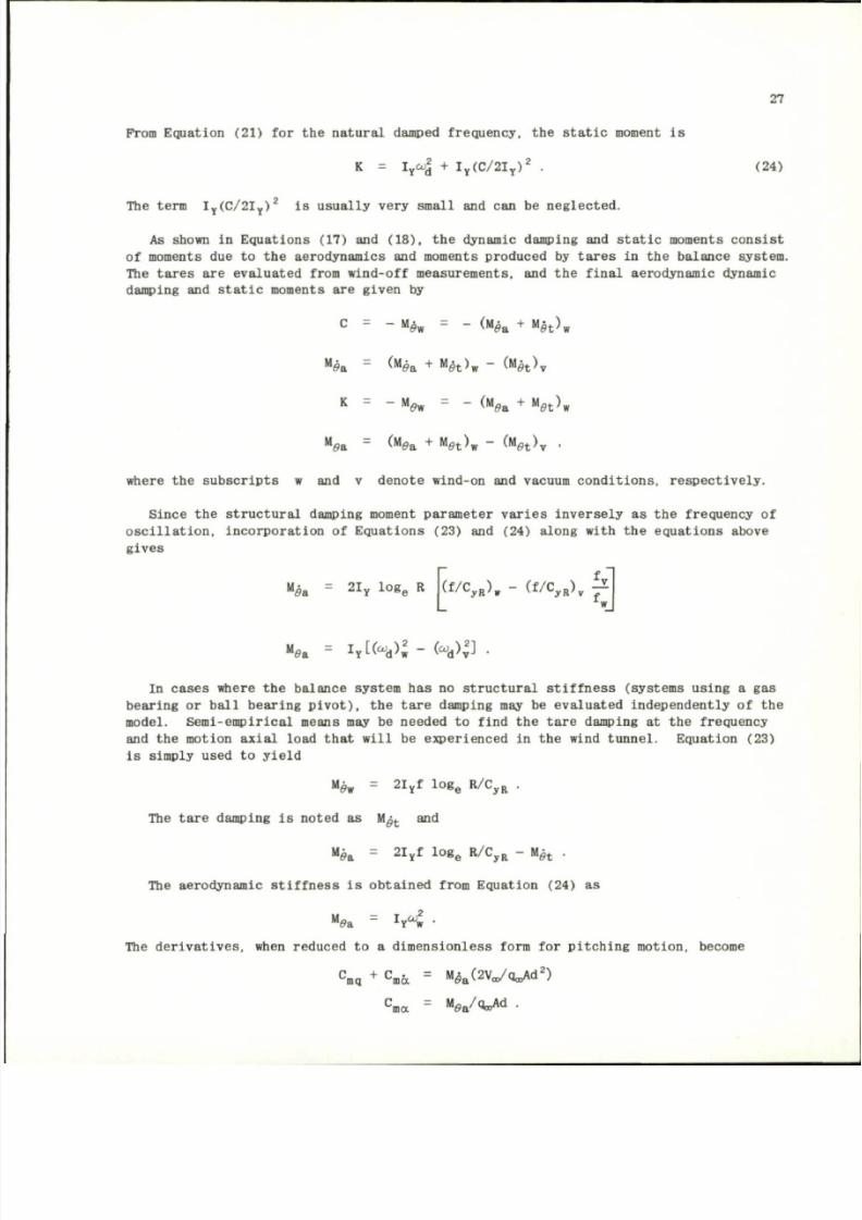
8/10/2019 Techniques for Measurement of Dynamic Stability Derivatives in Ground Test Facilities
http://slidepdf.com/reader/full/techniques-for-measurement-of-dynamic-stability-derivatives-in-ground-test 47/236
27
Prom Equat ion ( 2 1 ) f o r t h e na tu ra l damped f r eque ncy , t h e s t a t i c moment i s
K = I
Y
OJ2 + i
Y
( c / 2 I
y
)
2
. (24 )
The term I
y
( C / 2 I
y
)
2
i s
u s u a l l y v e r y s m a l l
an d can b e
n e g l e c t e d .
As shown i n E q u a t i o n s ( 1 7 ) a n d ( 1 8 ) , t h e dynamic damping and s t a t i c m om en ts c o n s i s t
of moments d u e t o t h e a e r o d y n a m i c s a n d moments produced by t a r e s i n t h e ba l anc e s ys tem .
T h e t a r e s a r e ev a l ua ted f rom w ind-o f f m eas u remen ts , a n d t h e f i na l ae rodynam ic dynamic
damping and s t a t i c m om en ts a r e g i v e n by
C = -
M
0w
=
~ ^
M
0a
+
M
0t^w
M
0a
=
<
M
(?a +
M
£t>w " ^
U
h \
K = _ M
0w
=
- <
M
ea
+
M
6»t^w
M
0a
=
(
M
0a
+ M
0t^w ~ (
K
e t \ '
where th e su bs cr ip t s w and v den ote w ind-on and vacuum co nd i t io ns , r e sp ec t iv e l y .
S ince th e s t r u c t u ra l damping moment param eter va r i es in ve r se ly as th e f r equency of
o s c i l l a t i o n , i n c o r p o r a t i o n o f E q u a t i o n s ( 2 3) an d ( 24 ) a l o n g w i th t h e eq u a t i o n s abo ve
g i v es
M
ffa
= 2 I
y
l o g
e
R
(f/C
yR
)
w
-
(f/C
yR
)
v
£
"(9a
= i i W * ) : - « * > j ] •
I n c a s e s w he re t h e b a l an ce s y s tem h as n o s t r u c t u r a l s t i f f n e s s ( s y st ems u s i n g a g a s
b ea r i n g o r b a l l b ea r i n g p i v o t ) , t h e t a r e d amp in g may b e ev a l u a t ed i n d ep en d en t l y o f t h e
model . Se m i-em pir ic al means may be needed to f ind t he ta re damping at th e f requency
and the mot ion ax ia l load th a t w i l l be expe r ience d in the w ind tu nn el . Equat ion (23)
i s s imply used to y ie ld
M
5w
= 2 I
y
f l o g
e
R /C
yR
.
The ta re damping is noted as M^
t
and
Mg
a
= 21
Y
f log
e
R /C
yR
- Mg
t
.
The aerodynamic s t i f fn e s s i s ob ta in ed f rom Equat ion (24) as
M
0a = h
w
l •
The de r i va t i ve s , when reduced to a d im ens ion les s form for p i t ch in g mot ion , become
C
mq
+ C
ma = U^MjoJid
2
)
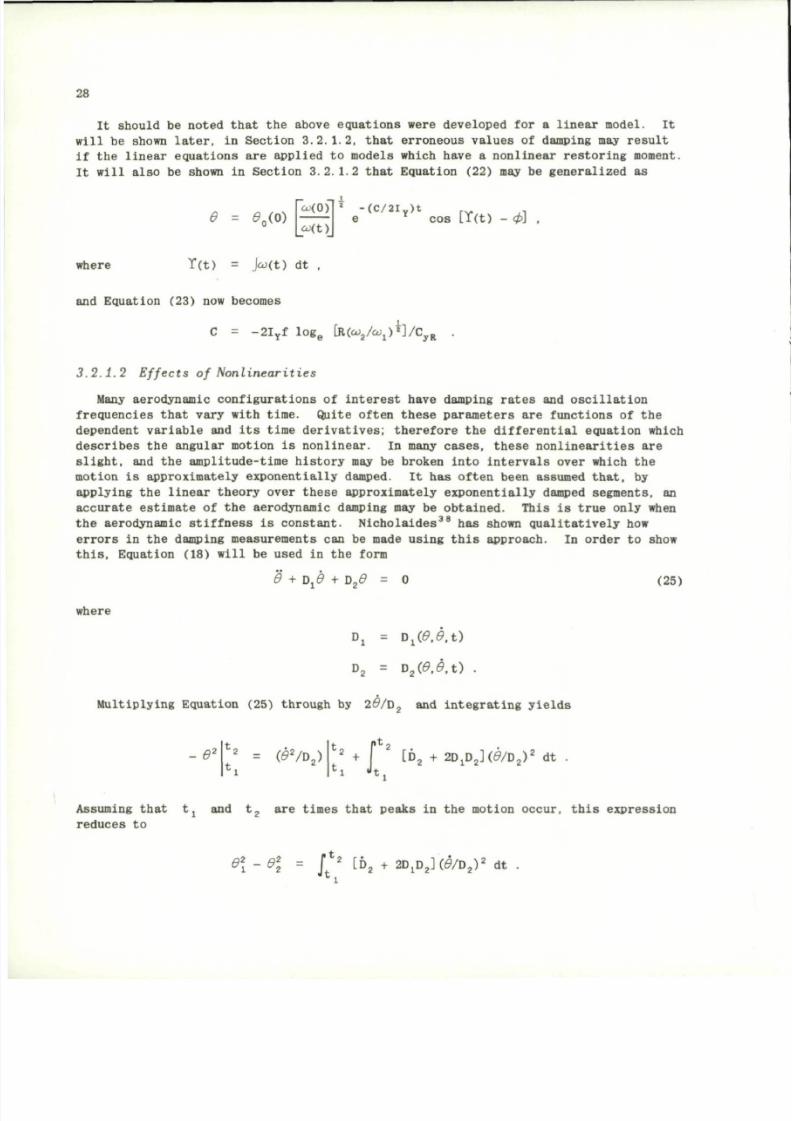
8/10/2019 Techniques for Measurement of Dynamic Stability Derivatives in Ground Test Facilities
http://slidepdf.com/reader/full/techniques-for-measurement-of-dynamic-stability-derivatives-in-ground-test 48/236
28
It should be noted that the above equations were developed for a linear model. It
will be shown later, in Section 3.2.1.2, that erroneous values of damping may result
if the linear equations are applied to model s which have a nonlinear restoring moment.
It will also be shown in Section 3.2.1.2 that Equation (22) may be generalized as
0 =
* o < ° >
co(0)
co(t)
-(C/2I
Y
)t
r v
..
e
Y
cos [T(t) -
cp]
where T(t) = jco(t) dt
and E quation (23) now becom es
C = -2I
y
f l o g
e
[R(OJ
2
/O;J)*]/C
.VR
3 . 2 . 1 . 2 E f f e c t s o f N o n l i n e a r i t i e s
Many aerodynamic configurations of interest have damping rates and oscillation
frequencies that vary with time. Quite often these paramete rs are functions of the
dependent variable and its time derivatives; therefore the differential equation which
descr ibes the angular motion is nonlinear. In many cases, these nonlinearities are
slight,
and the amplitude-time history may be broken into intervals over which the
motion is approximately exponentially damped. It has often been assumed that, by
applying the linear theory over these a pproximately exponentially damped segments, an
accurate estimate of the aerodynamic damping may be obtained. This is true only when
the aerodynamic stiffness is constant. Ni ch ol ai de s
38
has shown qualitatively how
errors in the damping measurements can be made using this approach. In order to show
this,
Equation (18) will be used in the form
9
+ Dj0 + D
2
£ =
(25)
where
Dj = Dj(0.r?.t)
D
2
=
D
2
( 0 . 0 . t )
.
Multiplying Equation (25) through by 2#/ D
2
and integrating yiel ds
- 0 ' ( S
2
/ D
2
)
|t
2
P*
2 ..
n
J
t.
+ 2DjD
2
]((9/D
2
)
2
dt
Assuming th a t t j and t
2
a r e t i me s t h a t p eak s i n t h e mo t io n o ccu r , t h i s ex p r e s s i o n
r ed u ces t o
d \ - 0 \ - J '
2
[D
2
+ 2 D j D
2
] ( ^ / D
2
)
2
d t
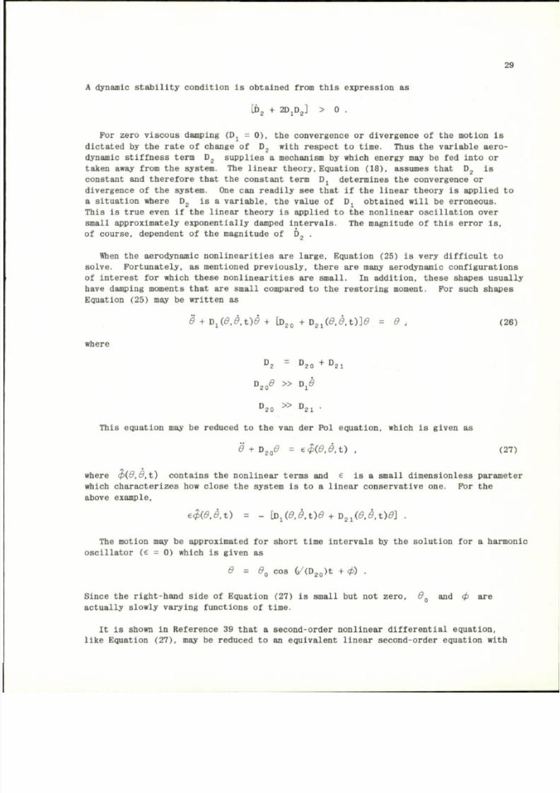
8/10/2019 Techniques for Measurement of Dynamic Stability Derivatives in Ground Test Facilities
http://slidepdf.com/reader/full/techniques-for-measurement-of-dynamic-stability-derivatives-in-ground-test 49/236
29
A dynamic stability condition is obtained from this expression as
[ t
2
+ 2DjD
2
] > 0 .
For zero viscous damping (Dj = 0 ) , the convergence or divergence o f the motion is
dictated b y the rate of change o f D
2
with respect t o time. Thus the variable aero
dynamic stiffness term
D
2
supplies
a
mechanism
by
which energy may
be fed
into
or
taken away from the system. The linear theory, Equation (18), assumes that D
2
is
constant and therefore that the constant term D j determines the convergence or
divergence
o f
the system. One can readily see that
if
the linear theory
is
applied
t o
a situation where
D
2
is a
variable, the value
o f Dj
obtained will
b e
erroneous.
This is true even if the linear theory is applied t o the nonlinear oscillation over
small approximately exponentially damped intervals. The magnitude o f this error i s ,
of course, dependent
of
the magnitude
o f D
2
.
When the aerodynamic nonlinearities are large, Equation (25)
is
very difficult
to
solve. Fortunately, as mentioned previously, there are many aerodynamic configurations
of interest for which these nonlinearities are small. In addition, these shapes usually
have damping moments that are small compared
to
the restoring moment.
For
such shapes
Equation (25)
may be
written
as
6 + V ^ 0 , 0 . t )0 + [D
20
+ D
2 l
( d . e . t ) ] 6 = d . (26)
where
D
2
= D
2 0
+ D
2 1
D
2 0
# » D.e
D
20 » °2l •
This equation may
b e
reduced
t o
the van der Pol equation, which
is
given
as
6 + D
20
d = e $ ( 0 . 0 . t ) . (27)
where < p ( 0 , 0 , t ) contains the nonlinear terms and e is a small dimensionless parameter
which characterizes how close the system
is to a
linear conservative one. For
the
above example,
e $ ( 0 . 0 . t )
= -
\D . (6 . e . t )d + D
2 1
(0 ,0 . t )0 ]
The motion may
b e
approximated for short time intervals
by
the solution
for a
harmonic
oscillator (e = 0) which is given as
0 = 0
O
co s (/(D
20
)t + cp) .
Since the right-hand side of Equation (27) is small but not zero, 0 and cp are
actually slowly varying functions
of
time.
It i s shown in Reference 39 that a second-order nonlinear differential equation,
like Equation (27), may be reduced to an equivalent linear second-order equation with
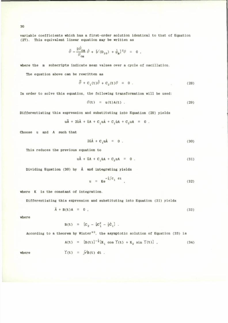
8/10/2019 Techniques for Measurement of Dynamic Stability Derivatives in Ground Test Facilities
http://slidepdf.com/reader/full/techniques-for-measurement-of-dynamic-stability-derivatives-in-ground-test 50/236
30
v a r i a b l e c o e f f i c i e n t s w h ic h h a s a f i r s t - o r d e r s o l u t i o n i d e n t i c a l t o t h a t of E q u at io n
(27).
T h i s eq u i v a l en t l i n ea r eq u a t i o n may b e w r i t t e n a s
a 20
- r ^ 0
+
[/(D
20
)
+
c p
m
]
2
0 = 0 .
om
where the m subscripts indicate mean values over a cycle o f oscillation.
The equation above can
be
rewritten
as
0 + Cj(t)(9 + C
2
( t ) 0 = 0 . (28)
In order t o solve this equation, the following transformation will b e used:
0 ( t ) = u(t)A(t) . (29)
Differentiating this expression
and
substituting into Equation (28) yields
uA + 2uA + iiA + CjUA + CjUA + C
2
uA = 0 .
Choose u and A such that
2uA + CjUA = 0 . (30)
This reduces the previous equation to
uA
+ UA +
CjUA
+
C
2
uA
= 0
.
(31)
Dividing Equation (30)
by A and
integrating yie lds
-i/c dt
u = K e
1
, (32)
where K is the constant of integration.
Differentiating this expression and substituting into Equation (31) yields
A + B(t)A = 0 . (33)
where
B(t) = [C
2
- i p \ - jCj] .
According to a theorem by Winter
40
, the asymptotic solution of Equation (33) is
A(t) = [B(t)]'*[Kj cos Y(t ) + K
2
sin T(t )] , (34)
where T ( t ) = J"/B(t) dt .
8/10/2019 Techniques for Measurement of Dynamic Stability Derivatives in Ground Test Facilities
http://slidepdf.com/reader/full/techniques-for-measurement-of-dynamic-stability-derivatives-in-ground-test 51/236
31
This solution applies after a finite length of time has elapsed, such that the oscilla
tory motion approaches being periodic.
It is interesting to note that for certain forms of B(t) , Equation (33) may be
reduced to Bessel' s dif ferential equation.
Equations (29), (32), and (34) may be combined and manipulated algebraically to
yield
0( t) = 0(0)
B(0)
B(t)
-ijc,(t) dt
e cos [T(t) + cp] , (35)
where 9 ( 0 ) and B(0) are the values of envelope amplitude and C(t ) respectively
at t = 0 .
For the case being considered, where Cj varies slowly and is small compared to
C
2
, B(t) given in Equation (33) may be reduced to
B = co
2
~ C
2
.
The following form of Equation (35) may be applied over intervals of the d ata where
Cj is approximately constant:
l i i
— ' e '
T C l t
cos [Y(t) + cp] ,
co(t)j
where
T(t)
= f co ( t ) dt
J
o
Cj = C/I
Y
.
In order to use this solution to determine Cj . co and y must be known as functions
of time. •
3 . 2 . 1 . 3 F r ee O s c i l l a t i o n ( T hr ee D eg r ee s o f F r eed om)
Solutions of the equations of motion referenced to the nonrolling coordinates will
be obtained in this section*. For this development it is assumed that the model has
triagonal or greater symmetry and that the XYZ axes correspond to the principal
inertia axes of the model. The effects of slight asymmetries of the model will be
considered, i.e., asymmetries which have a negligib le effect on the above assumptions.
3 . 2 . 1 . 3 . 1 E q u a t i o n o f P i t ch i n g an d Y awing M o t io n s
For a model of the above type rotating about a point fixed in space, Equations (5)
describe the motion.
• These methods have been extracted from References 38 and 41.
8/10/2019 Techniques for Measurement of Dynamic Stability Derivatives in Ground Test Facilities
http://slidepdf.com/reader/full/techniques-for-measurement-of-dynamic-stability-derivatives-in-ground-test 52/236
32
Iq + I
Y
Pr
(SM)« =
p
V
2
Ad
(36)
Ir - I
Y
Pq = (2M)ar =
p
V„Ad
~
(37)
where I = Is = Ig .
For motion about
a
point fixed
in
space,
= a
* * - f l .
The angular rates in the nonrolling coordinate system are given as
q = q cos $ - r sin $
r = r cos $ + q sin $ ,
where
$
~ f P(t) dt .
Jo
Substituting
the
angular rate s gi ven in Equatio ns ( 4 ) , these expressions reduce
to
q
= e
r = y/ co s
d .
When the motion is restricted to small angular excursions
( d «
l ) , Equations (39)
reduce
t o
(38)
(39)
q =
0
(40)
Multiplying Equation (36) by i and subtracting Equation (37) from it, these equations
may
be
combined
to
form
a
single diffe rential equation
I(-r + iq) - iI
x
P(-r + iq) = iqo,Ad(C
m
+ i C
n
) .
Assuming small angular excursions
and
substituting
the
time derivatives
of
Equations
(38) and (40) into the equation above yields
1 0
+
la) - iI
x
PC§ + lot) = iqa,Ad(C
m
+ i C
n
)
8/10/2019 Techniques for Measurement of Dynamic Stability Derivatives in Ground Test Facilities
http://slidepdf.com/reader/full/techniques-for-measurement-of-dynamic-stability-derivatives-in-ground-test 53/236
33
The complex angle of attack may be reduced to
v + iw
S = ~ p + i a ,
V
c
w here i t i s a ss umed t h a t / 3 ~ v / V
c
and 6c ~ w/V
c
. S u b s t i t u t i n g t h e t im e d e r i v a t i v e s
of th i s complex angle in to the equat ion of mot ion ,
I < f - i I
x
P g - = iq^AdCC,,, + i C
n
) . (41 )
Assuming that first-order linear aerodynamics
are
adequate
and
that
t he
motion
is
described by oc , /3 , cc , /3
,
P , q , a nd r , t h e pitching- and yawing-raoment c o
efficients a r e given in th e body coordinates XYZ as
C
« =
C
mo
+
V
+
C
mq
g ©
+
c
ma
W
+
C
m p
/ ^
c
n = c
n0
+ V ? + c
nr
( ^ + c
n/
g (~J +
c
npa
a ( ^ J .
The terms C
m 0
and C
n 0
were Include d in this expansion o f t h e coefficients t o account
fo r th e assumed slight asymmetry o f t h e model*. A s outlined by Murphy"
1
, th e Magnus
coefficients,
C
n
• , C
A ,
C „
p
, and C ,
have
a
negligible effect
on the
motion;
therefore they were not included.
Fo r
a
missi le with triagonal
o r
greater symmetryt.
C
n/3
C
n £
C
n r
-
=
=
ma
ma
mq
-
=
=
~
C
M a
-
C
M a
C
M q
C
np a
C
»p/3 ~
C
np a •
Substitute these relations into t h e yawing-moment equation, then mult iply t he result
by
i and add it to the
pitchi ng-moment equation
t o
obtain
K C , + ic
n
) = i ( c
B 0
+ ic
n0
) + c
Ma
(/3 + ia ) +
+ (c
Mq
+
c
u 6
) 0 + id)
— +
c
Mpa
(/3
+
ia)p
,
•
This approach was first used
by
Nicolaides
42
in
his development
o f
the "Tricyclic" theory,
t See References 38 and 41 for a discussion of symmetry.
8/10/2019 Techniques for Measurement of Dynamic Stability Derivatives in Ground Test Facilities
http://slidepdf.com/reader/full/techniques-for-measurement-of-dynamic-stability-derivatives-in-ground-test 54/236
34
where
P = Pd/2V
C
.
Substituting
the
complex angle
o f
attack referenced
to the
body coordinates,
£ 2. fi +
ia ,
into t he above relation yields
1
<
C
.
+
i c
n> = i ^ m o
+
i c
no )
+
C
Ma
<f
+
_£d
2V„
+
<
C
Mq
+
< W
—
+
C
M p a
^ P
. (42)
It
now
becomes necessary
to
transform these coe fficie nts from
the
body coordinates
to t he nonrolling coordinates. Thi s transformation is given as
i(C
m
+ i C
n
) e
1 $
= i ( C
m
+ i C
n
) .
The t r a ns f orm at i on for the complex ang le of a t t a ck i s g iven as
T h i s i s e a s i l y p ro v ed b y ex p an d in g t h i s r e l a t i o n an d eq u a t i n g r ea l and i mag i n ar y
p a r t s a s f o l l o w s
/v + iw \ v + iw
(co s $ + 1 s in $) =
\ \ J
v = v co s $ + w si n $
w = w co s $ - v si n $ .
T h e s e r e l a t i o n s a r e t h e n o n r o l l i n g v e l o c i t y c o m p o n e n t s
4 1
Murphy
41
us ed t h e ab ov e t r an s f o r ma t i o n t o t ran s f o r m E q u a t i o n ( 4 2 ) t o t h e n o n r o l l i n g
co o r d i n a t e s . T he r e s u l t may b e w r i t t e n a s
i( C
m
+ C
n
) = i(C
m Q
+ i C
n 0
) e
1 $
+ C
M
J +
+
(
C
M q
+
<W j f
+
U *
D
JP •
S u b s t i t u t i n g t h i s r e l a t i o n i n t o E q u a ti o n (4 1 ) r e s u l t s i n
| + (G + 1 H ) | + ( J + 1 K ) | = L e
i p t
, (43)
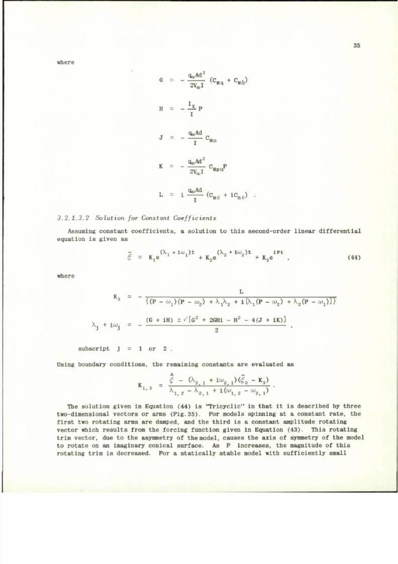
8/10/2019 Techniques for Measurement of Dynamic Stability Derivatives in Ground Test Facilities
http://slidepdf.com/reader/full/techniques-for-measurement-of-dynamic-stability-derivatives-in-ground-test 55/236
35
where
^
M 2
/ x
G =
-
i n
(c
»*
+
^
H = - P
QooAd
J
= ~ —
C
M a
K - ^ C P
2 V . I
M p a
L
= i ~ <
C
mo
+ i C
no) •
3 . 2 . 1 . 3 . 2 S o l u t i o n f o r C o n s ta n t C o e f f i c i e n t s
Assuming constant coefficients, a solution to this sec ond-order linear diff erential
equation
is
given
a s
~ (X
+ l<a,)t (X ,
+
ico
)t iPt
<f = Kje
l 1
+ K
2
e
2 2
+ K
3
e . (44)
where
K
3 = "
X..,
+ i w,
{(P -
e o . ) ( P
- co
2
) + \ j \
2
+ i[Xj(P -
o>
2
)
+ X
2
( P -
c o . ) ] }
(G
+
iH)
±
/ [ G
2
+
2GHi
- H
2
- 4(J + IK)]
subscript
j = 1 or 2 .
Using boundary conditions, t he remaining constants are evaluated as
I ~ <
k
2 1
+ l a
V l ) ^ 0 -
R
3
)
K
1 ,2 X
l , 2
-
k
2 .
1
+
i K . 2
W
2 . 1>
The solution given
in
Equation
(44) is
"Tricyclic"
in
that
it is
described
by
three
two-dimensional vectors
or
arms
(Fig.35). For
mod els spinning
at a
constant rate,
t h e
first two rotating arms a re damped, and the third is a constant a mplitude rotating
vector which results from the forcing function given in Equation (43). Thi s rotating
trim vector,
d u e t o t h e
asymmetry
o f
the
model,
causes
t he
axis
o f
symmetry
of the
model
to rotate o n an imaginary conical surface. A s P increases, the magnitude of this
rotating trim is decreased. For a statically stable model with sufficiently small
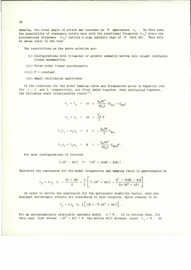
8/10/2019 Techniques for Measurement of Dynamic Stability Derivatives in Ground Test Facilities
http://slidepdf.com/reader/full/techniques-for-measurement-of-dynamic-stability-derivatives-in-ground-test 56/236
36
damping, the total angle of attack may increase as P approaches co^ . In this case,
the possibility of resonance exists only with the nutational frequency
(co
x
)
since the
precessional frequency
(co
2
)
car ries a sign opposite that of P ( R e f . 3 8 ) . This will
be shown later in the text.
The restrictions on the above solution are:
(i) Configurat ions with triagonal or greater symmetry having only slight configura-
tional asymmetries.
(ii) First-order linear aerodynamics.
(iii) P = constant.
(iv) Small oscillation amplitudes.
If the relations for the modal damping rates and frequencies given in Equation (44)
for j = 1 and 2, respectively, are first added together, then multiplied together,
the following exact relationships result"
1
:
k
*
+
K =
"
G =
l £ j
( C
«
+
° ^
x
x
co, + com
= -H = — P
1 2
I
\A.
2
- co.co. = J = — c
M a
aa,Ad
V
2
+ K.CO. = K = - ^ — C
M p a
P
For most configurations of interest
I ( - H
2
- 4 J ) | » |(G
2
+ 21GH - 41K)
Therefore the expression for the modal frequencies and damping rates is approximated by
v/{-(H
2
+ 4J)} +
, (G + iH) 1
X-4 + ico. ~ ± -
J J o o
G
2
+ 2iGH - 4iK
2iv(H
2
+ 4J)
In order to derive the expression for the gyroscopic stability factor, only p r e
dominant aerodynamic effects are considered in this relation, which reduces it to
Xj + l&)j ~ |[-i H ± i/{-(H
2
+ 4J)}] .
For an aerodynamically statically unstable model, J < 0 . It is obvious then, for
this case, that unless - (H
2
+ 4J) < 0 the motion will diverge, since Xj > 0 . If
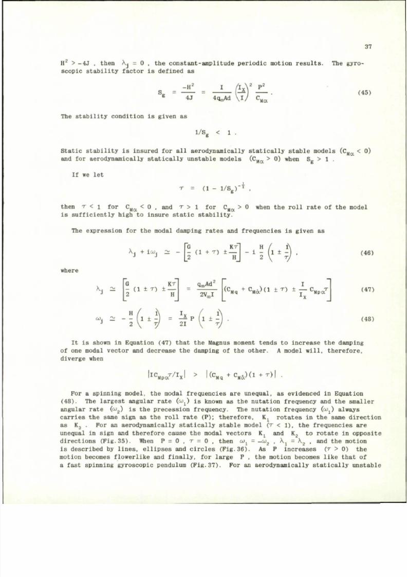
8/10/2019 Techniques for Measurement of Dynamic Stability Derivatives in Ground Test Facilities
http://slidepdf.com/reader/full/techniques-for-measurement-of-dynamic-stability-derivatives-in-ground-test 57/236
37
H
2
> - 4 J , t h en X , = 0 , t h e co n s t a n t - am p l i t u d e p e r i o d i c mo ti on r e s u l t s . T he g y r o
s c o p i c s t a b i l i t y f a c t o r i s d e f in e d a s
-H '
4J
n
x
V P
2
4q
C0
Ad \ I / C
(45)
'MO
The stability condition is given as
1/S
g
< 1 .
Static stability
is
insured
for all
aerodynamlcally statically stable models ( C
H a
< 0)
and for aerodynamically statically unstable models ( C
M a
> 0) when S > 1 .
If
we let
T
= (i -
i/ s
g
r*,
then T < i f o r C
u
„ < 0 , and T > 1 for C
u
„ > 0 when the roll rate of the model
Ma
Ma
is sufficiently high
to
insure static stability.
The expression for the modal damping rates and f requencies is given a s
Xj
+ i^j - -
G K r
- (1 + T ) ± _
2
H
H
f
1
- 1 ±
2 V T,
(46)
where
K
i ~
G
KT
- (1 ±
T)
±
—
2 H
2V
m
I
<
C
Mq
+ C
M a > d ±
T
>
±
-
C
H
P 0
7
(47)
H
2
J
I
1 1
; ;
=
n
p {
(48)
It
is
shown
in
Equation (47) that
t he
Magnus moment tends
to
increase
the
damping
of o ne modal vector and decrease the dampi ng of the other. A model will, therefore,
diverge when
I^Mpa^xl
(C
Mq
+
c
M&
)(i
+ r ) |
For a spinning model, the modal frequencies are unequal, as evidenced in Equation
( 4 8 ) .
The
largest angular rate (co^)
is
known
as the
nutation frequency
and the
smaller
angular rate
(c o
2
)
is the prec ess ion frequency. The nutation frequency
( c o j
always
carries t he same sign as the roll rate (P); therefore, K j rotates in the same direction
as
K
3
. For an
aerodynamically statically stable model ( r < \ ) ,
th e
frequencies
are
unequal
in
sign
and
therefore cause
t he
modal vectors
K
x
and K
2
to
rotate
in
opposite
directions (Fig.
3 5 ) .
When P = 0 , T = 0 , then ojj = _o;
2
, X., = X_ , and the motion
is described by lines, ellipses and circl es (Pig. 3 6 ) . A s P increases ( T > 0) the
motion becomes flowerlike
and
finally,
for
large
P
,
the
motion becomes like that
of
a fast spinning gyroscopic pendulum (Pig. 3 7 ) .
For an
aerodynamically statically unstable
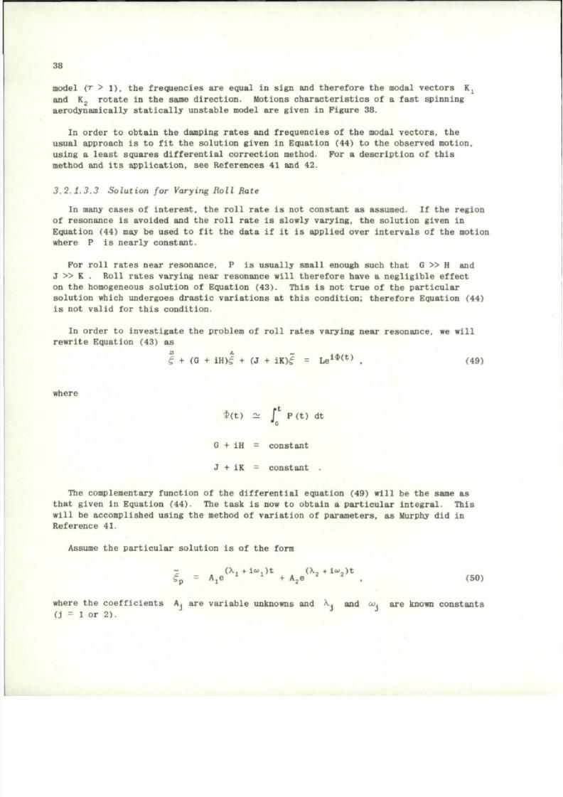
8/10/2019 Techniques for Measurement of Dynamic Stability Derivatives in Ground Test Facilities
http://slidepdf.com/reader/full/techniques-for-measurement-of-dynamic-stability-derivatives-in-ground-test 58/236
38
model (r > l ) , th e frequencies are equal in sign and therefore t he modal vectors K j
and
K
2
rotate
in the
same direction. Motions characteristics
of a
fast spinning
aerodynamically statically unstable model
are
given
in
Figure
38.
In orde r
to
obtain
the
damping rates
and
frequencies
of the
modal vectors,
t h e
usual approach
is to fit the
solution given
in
Equati on (44)
to the
observed motion,
using a least squares differential correcti on method. For a description of this
method and its application, see References 41 and 42.
3 . 2 . 1 . 3 . 3 S o l u t i o n f o r V a ry in g R o l l R at e
In many cases
of
interest,
the
roll rate
is not
constant
as
assumed.
If the
region
of resonance is avoided and the roll rate is slowly varying, the solution given in
Equation (44) may be used to fit the data if it is applied over intervals of the motion
where
P is
nearly constant.
For roll rates near resonance,
P is
usually small enough such that
G » H and
J
» K
. Roll rates varying near resonance will therefore have
a
negligible effect
on
th e
homog eneous solution
of
Equation (43). This
is not
true
of the
particular
solution which undergoes drastic variations at this co ndition; therefore Equation (44)
is no t valid for thi s condition.
In orde r to investigate the problem of roll rates varying near resonance, we will
rewrite Equation
(43) as
1 + (G +
i H ) |
+ (J +
1 I ) |
s
L e
i $ ( t )
, (49)
where
$(t )
2 . / P ( t ) dt
"o
G
+ iH =
constant
J
+ IK =
constant
The complementary function
of the
diff erential equation (49) will
be the
same
as
that given
in
Equation (44).
T he
task
is now to
obtain
a
particul ar integral. This
will be accomplis hed using the method of variation of parameters, as Murphy did in
Reference
41.
Assume
the
particular solution
is of the
form
~ (X +lo. )t (X,+i<u)t
<f
p
= Aje
x J
+ A
2
e
2 2
. (50)
where th e coefficients Aj are varia ble unknowns and X . and
oo .
are known consta nts
(j
= 1 or
2).
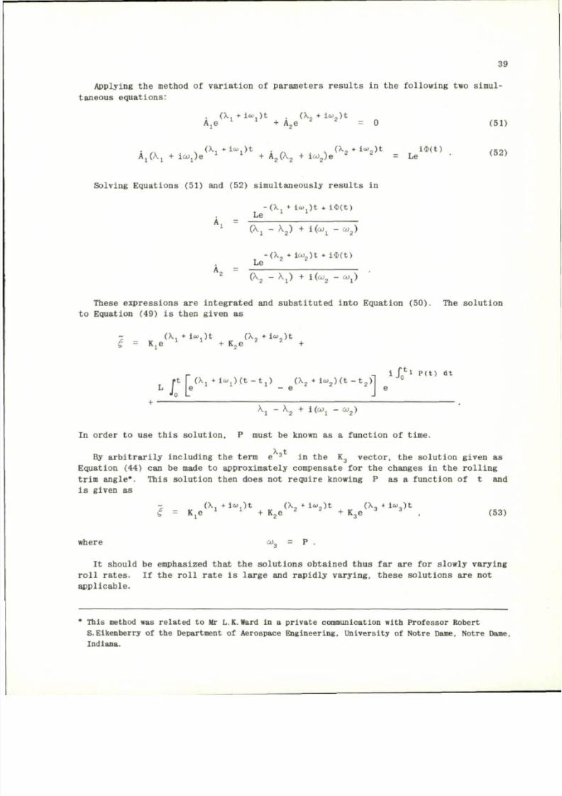
8/10/2019 Techniques for Measurement of Dynamic Stability Derivatives in Ground Test Facilities
http://slidepdf.com/reader/full/techniques-for-measurement-of-dynamic-stability-derivatives-in-ground-test 59/236
39
A p p l y i n g t h e me t h o d o f v a r i a t i o n o f p a r ame t e r s r e s u l t s i n t h e f o l l o w i n g t w o s i mu l
t an eo u s eq u a t i o n s :
( X , * l « . ) t (X • lo> ) t
Aje
x 1
+ A
2
e
2 2
= 0 (5 1)
. (X • « ) t (X + 1« )t i<P(t) ,- n s
A j ( X j + i o ; j ) e
x J
+ A
2
(X
2
+ io;
2
)e
2
= Le
( 5 2 )
S o l v i n g E q u a t i o n s ( 5 1 ) an d ( 5 2 ) s i mu l t an eo u s l y r e s u l t s i n
- (X , + i<a ,) t + l $ ( t )
Le
1 :
1
(Xj - X
2
) + i (co. -c o
2
)
- (X, • ico ) t * i$( t )
Le
2 2
A
2
( X
2
- X j ) + 1 ( 0 J
2
- CDj)
T h es e ex p r e s s i o n s a r e i n t eg r a t e d and s u b s t i t u t ed i n t o E q u a t i o n ( 5 0 ) . T he s o l u t i o n
to Equat ion (49) is then given as
- ( X , + l « j ) t ( X , + l « . ) t
£ = Kje
x :
+ K
2
e
2 2
+
r -i i / n *
1 P ( t ) d t
r t | (Xj • l »
1
) ( t - t
1
) (X
2
• l «
2
) ( t - t
2
) l
' o
e
^ 1 -
x
2
+ K ^j - ^
2
)
In ord er to use t h i s so l u t io n , P must be known as a fun c t io n of t ime.
By a r b i t r a r i l y i n c l u d i n g t h e t er m e
3
in th e K
3
v ec t o r , t h e s o l u t i o n g i v en a s
Equat ion (44) can be made to appro xim ate ly compensa te for the changes in th e ro l l in g
t r im angle* . Thi s so lu t io n then does no t r e qu i re knowing P as a func t ion of t and
is given as
- (X. * l » . ) t ( \ , * i c o ) t ( X . + i o O t
<f = Kje
i 1
+ K
2
e
2 2
+ K
3
e
3 3
(53)
where co
3
= P .
I t s h o u ld be emp h asi zed t h a t t h e s o l u t i o n s o b t a i n ed t h u s f a r a r e f o r s l o w l y v a r y i n g
r o l l r a t e s . I f t h e r o l l r a t e i s l a r g e an d r a p i d l y v a r y i n g , t h e s e s o l u t i o n s a r e n o t
a p p l i c a b l e .
* This method was re la te d to Mr L.K.Ward in a p ri v a te communication with Pr ofe sso r Robert
S.Eikenberry of the Department of Aerospace Engineering, University of Notre Dame, Notre Dame,
Indiana.
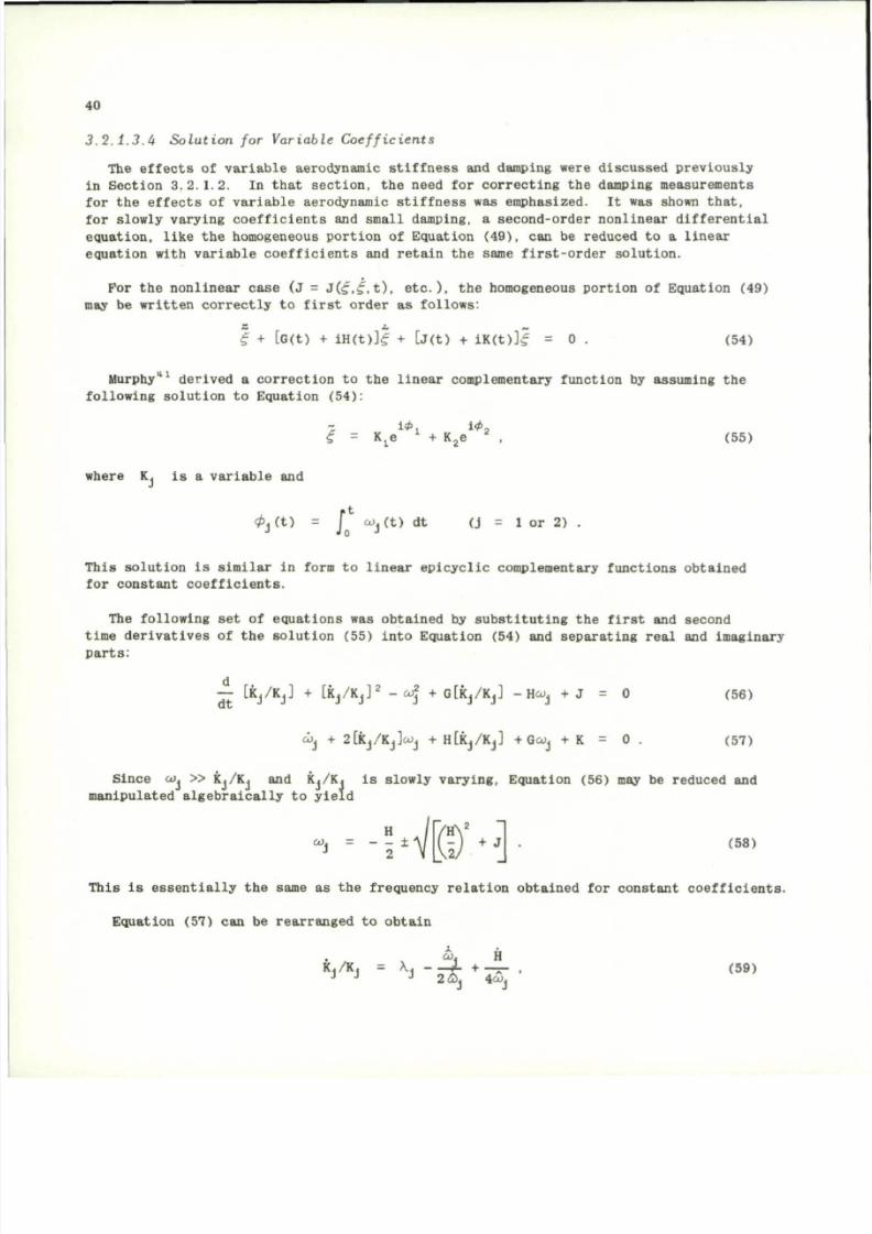
8/10/2019 Techniques for Measurement of Dynamic Stability Derivatives in Ground Test Facilities
http://slidepdf.com/reader/full/techniques-for-measurement-of-dynamic-stability-derivatives-in-ground-test 60/236
40
3 . 2 . 1 . 3 . 4 S o l u t i o n f o r V a r i a b l e C o e f f i c i e n t s
The effects o f variable aerodynamic stiffness and damping were discussed previously
in Section 3.2.1.2.
In
that section,
the
need
for
correcti ng
the
damping measurements
for
t he
effects
o f
variable aerodynamic stiffness
was
emphasized.
It was
shown th at,
for slowly varying coefficients and small damping, a second-order nonlinear differe ntial
equation, like t h e homogeneous portion of Equation (49), can be reduced to a linear
equation with variable coefficients and retain the same f irst-order solution.
For the nonlinear case (J = J(£,s,t), etc.), the homogeneous portion of Equation (49)
may be written correct ly t o first or der a s fol lows:
£ + [G(t) + iH(t)]£ + [J(t) + l K ( t ) ] | = 0 . (54)
Murphy"
1
derived a correction to the linear compl ementary function b y assuming the
following solution to Equati on (54):
i*j i4 >
2
<f = K je
l
+ K
2
e
2
, (55)
where
K, is a
variable
and
c p
s
( t )
= j
o)j(t) dt (j = 1 or 2) .
T h i s s o l u t i o n i s s i m i l a r i n form t o l i n ea r ep i cy c l i c co mp lemen ta ry f u n c t i o n s o b t a i n e d
f o r c o n s t a n t c o e f f i c i e n t s .
T he f o l l o w i n g s e t o f eq u a t i o n s was o b t a i n ed b y s u b s t i t u t i n g t h e f i r s t and s eco n d
t i me d e r i v a t i v e s o f t h e s o l u t i o n ( 5 5 ) i n t o E q u a t i o n ( 5 4 ) and s ep a r a t i n g r ea l an d imag i n a r y
p a r t s :
—
[ K J / K J ]
+ [K j /K j ]
2
- c o
2
+ G[k j/Kj] -H ojj + J = 0 (56)
cJj + 2[k
j
/K
j
] a )
J
+ H [k j/ K j] + Goij + K = 0 . (57)
S in ce co »
KJ/KJ
and Kj/Kj i s s lowly va ryi ng , Equa t ion (56) may be reduc ed and
m a n i p u l a t e d a l g e b r a i c a l l y t o y i e l d
. 2
H
C O , = ±
J
2
H
+ J
2.'
(58)
This is essentially the same as the frequency relation obtained for constant coeff icients.
Equation (57) ca n be rearranged to obtain
c o , H
K./K, = X . (L + _ _ , ( 59)
2 <
%
4aJ
J
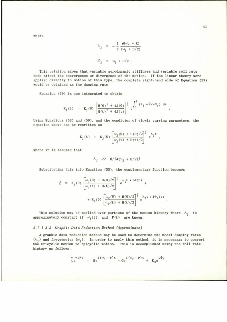
8/10/2019 Techniques for Measurement of Dynamic Stability Derivatives in Ground Test Facilities
http://slidepdf.com/reader/full/techniques-for-measurement-of-dynamic-stability-derivatives-in-ground-test 61/236
where
41
. 1 (Geo. + K)
2 (o)j + H /2)
J
Wj + H/2
This relation shows that variable aerodynamic stiffness and variable roll rate
both affect the convergence or divergence of the motion. If the linear theory were
applied directly to motion of this type, the complete right-hand side of Equation (59)
would be obtained as the damping rate.
Equation (59) is now integrated to obtai n
Kj(t) = Kj(0)
H ( 0 )
2
+ 4J(0)
11 J (Xj
+ H / 4 & J )
dt
H ( t )
z
+ 4J(t)
Using Equations (58) and (59), and t he condition of slowly varying para meter s, the
equation above can be rewritten as
Kj(t) = Kj(0)
c o ^ O ) + H(0)/2
«.(t) + H(t)/2
X.t
where it is assumed that
V, » H/{4(^j + H/2)} .
Substituting th is into Equation (55), the compl ementary function become s
Kj(0)
ojj(O) + H (0)/ 2
c o
x
( t ) + H(t) /2
X.t +l*(t )
e +
+ K
2
(0)
O J . ( O )
+ H(0)/2
- i '
c o
2
( t ) + H(t )/2
2
X
2
t + l *
2
( t )
e
This solution may be applied over portions of the motion history where X. is
approximately c onstant If c o . ( t ) and P(t ) are known.
3. 2 . 1 . 3 . 5 Graphic Data Red uct ion Method (Approximate)
A graphic data reduction method may b e used to determine the modal damping rates
(Xj) and f requencies (^j)- In order to apply thi s method, it is necessar y to convert
the tricyclic motion to epicyclic motion. This is accomplished using the roll rate
history as follows:
— ipt
f e
= Be
l(a>j-P)t l ( «
8
- P ) t
w
_ i $
0
+ Ce
+ K
3
e
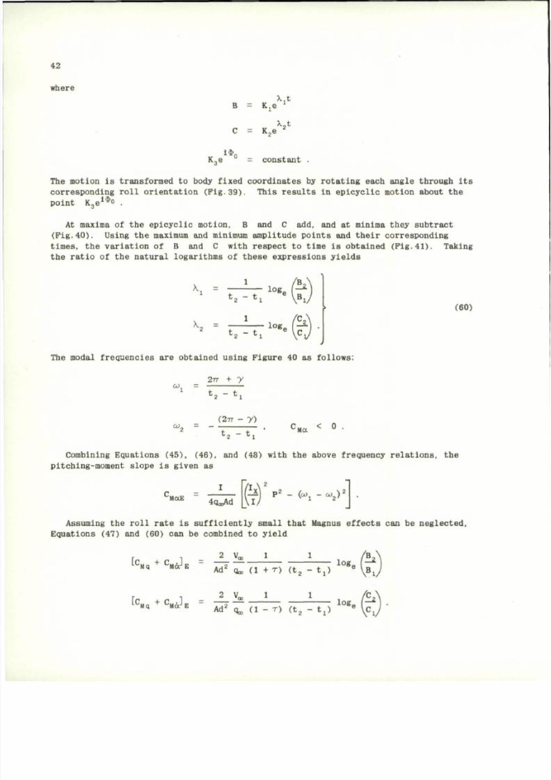
8/10/2019 Techniques for Measurement of Dynamic Stability Derivatives in Ground Test Facilities
http://slidepdf.com/reader/full/techniques-for-measurement-of-dynamic-stability-derivatives-in-ground-test 62/236
42
where
K
3
e
B
C
1»„
Kj6
Xjt
x,t
K
2
e
= constant
The motion
is
transformed
t o
body fixed coor dinates
b y
rotating each angle through
Its
corresponding roll orientation ( P i g . 3 9 ) . This results i n epicycl ic mot ion about t h e
point K
3
e
1 $ 0
.
At maxima o f t h e epicyclic motio n, B and C add, and at minima they subtract
( P i g . 4 0 ) . Using th e maximum a nd minimum amplitude points a nd their corresp onding
times, t h e variation of B and C with respect t o time i s obtained (Fig. 4 1 ) . Taking
the ratio
o f t h e
natural logarithms
o f
these expressions yiel ds
K. =
K
=
t
2
- tj
logo
/ r *
t
2
- t j
log.
•?
(60)
The modal frequencies a r e obtained using F igure 40 as fol lows:
2TT
+ y
co =
t
2
- t j
( 2 - n
-
22
t
a
- t j
C
Ma
< °
Combi ning Equatio ns (45), (46), and (48) wit h t h e above frequency relations, t h e
pitching-moment slope
i s
given
a s
'MaE
4qooAd
• f ] P
2
- K - C
2
)
•
Assuming t h e roll rate i s suffici ently small that Magnus effect s c a n b e neglected.
Equations (47) a nd (60) c a n b e combined t o yield
F 1 2 Vq, i
LC
M q
+ C
M a
J
E
A A
2
1
[c
+
c •] = — ^
L
S l q
+ L
M a
J
E
A A
2
A d ' Oa, ( 1 + r ) ( t
2
- t j )
1 1
log. I T *
A d ' q , ( 1 - r ) ( t
2
- t j )
l o g
e
' - *
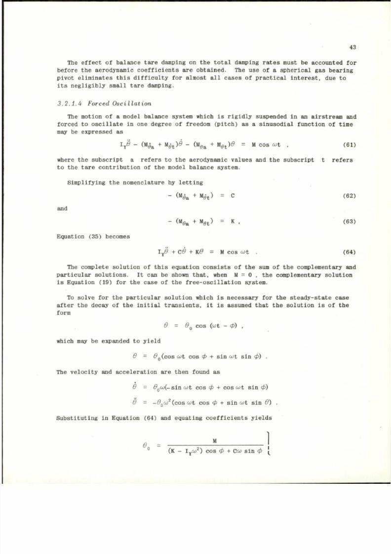
8/10/2019 Techniques for Measurement of Dynamic Stability Derivatives in Ground Test Facilities
http://slidepdf.com/reader/full/techniques-for-measurement-of-dynamic-stability-derivatives-in-ground-test 63/236
43
The effect of balance ta re damping on the total damping rates must be accounted for
before the aerodynamic coefficients are obtai ned. The use of a spherical gas bearing
pivot eliminates this difficulty for almost all cases of practical interest, due to
its negligibly small tare damping.
3.2.1. 4 Forced Osc ill ati on
The motion
of a
model balance system which
is
rigidly suspended
in an
airstream
and
forced
to
oscillate
in one
degree
of
freedom (pitch)
as a
sinusodial function
of
time
may be expressed as
1
Y
0 - (M^
a
+ Ug
t
)0 - (M
ea
+ H
e t
)0 = M cos cot , (61)
where the subscript a refers to the aerodynamic values and the subscript t refers
to the tare contribution of the mode l balance system.
Simplifying
the
nomenclatur e
by
letting
<
M
e
a
+
M
9t )
= c
<
62
>
and
Equation (35) beco mes
- (
M
e« + "st) =
K
. (63)
I
Y
(9 +
C0
+ K.0 = M cos
cot .
(64)
The complete solution
of
this equation consists
of the sum of the
complementary
and
particular solutions.
It can be
shown tha t, when
M = 0 , the
compleme ntary solution
is Equation (19) for the case of the free-os cillati on system.
To solve for the particu lar solution which is necessar y for the steady-state case
after the decay of the initial transients, it is assumed that the solution is of the
form
0 = 0
Q
cos (cot - cp) ,
which may be expanded to yield
0
= #
0
( c o s
cot
cos
cp
+
sin cot
sin
cp) .
The velocity and acceleration are then found as
0 = d
0
co(-sia cot
cos
cp
+ cos cot sin
cp)
d
=
-d
Q
co
2
(cos cot
cos
<P
+ sin
cot
sin
d) .
Substituting in Equat ion (64) and equating coefficients yields
*0
(K - I
y
oJ
2
) cos cp + Ceo sin cp
(
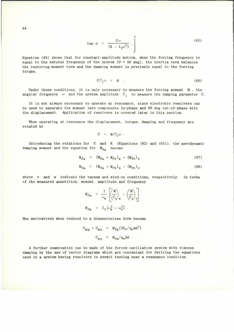
8/10/2019 Techniques for Measurement of Dynamic Stability Derivatives in Ground Test Facilities
http://slidepdf.com/reader/full/techniques-for-measurement-of-dynamic-stability-derivatives-in-ground-test 64/236
44
tan cp
Ceo
(65)
(K - I X )
Equa t ion (65) shows th a t fo r con s ta n t - am pl i tud e mot ion , when th e forc ing f r equency i s
equal to th e na tu ra l f r equency of th e sys tem (cp = 90 deg ) , th e in e r t i a t e rm b a la nce s
th e r es tor ing-mo me nt t e rm and the damping moment i s p re c i se ly eq ual to the forc ing
t o r q u e ,
C 0
Q
co
= M
(66)
Under these conditions, it is only necessary to measure the forcing moment M , t h e
angular frequency co and the system amplitude d
Q
t o measure the damping parameter C
It i s not always necessary t o operate at resonance, since electronic resolvers can
be used
t o
separate the moment into comp onents in-phase and
90
deg out-of-phase with
the displacement. Application o f resolvers i s covered later in this section.
When operating at resonance the displacement, torque, damping and frequency are
related by
C =
M/0
o
co
.
I n t r o d u c i n g t h e r e l a t i o n s fo r C an d K ( E q u a t i o n s (6 2 ) and ( 6 3 ) ) , t h e ae ro d y n ami c
damping moment and th e eq ua tio n for M ^ become
"0a
"0a
= (Mfl« + M fl
t
). - Olfe )
$t 'm
a
e t>v
(M„
B
+ M a
r
) . - O fe )
•0t 'w
et>\
(67)
(68)
where v and w in d ic a t e the vacuum and wind-on co nd i t i on s , r es pe c t iv e l y . In t e rms
of th e measured q u a n t i t i e s , moment, am pl i tude and f r equency
"0a
• M
o/w
.\r
The derivativ es when reduced
t o a
dimensionless form become
C
mq
+ C
m a = M ^ V a / q ^ A d
2
)
m a
= M f l a
/ a
-
A d
A further examination can b e made o f the forced oscillation system with viscou s
damping
b y
the use
o f
vector diagrams which are convenient for deriving the equations
used in a system having resolvers t o permit testing near a resonance condition.
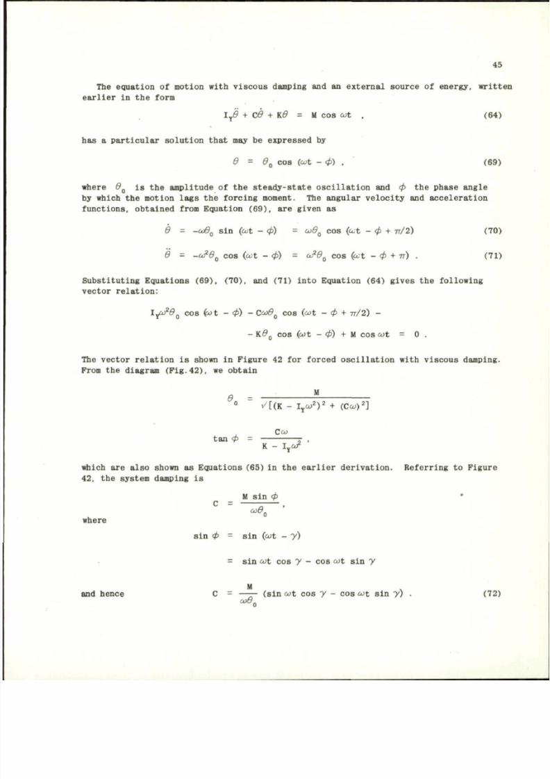
8/10/2019 Techniques for Measurement of Dynamic Stability Derivatives in Ground Test Facilities
http://slidepdf.com/reader/full/techniques-for-measurement-of-dynamic-stability-derivatives-in-ground-test 65/236
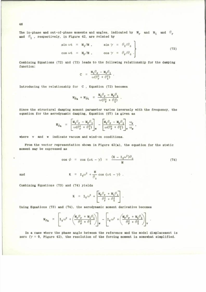
8/10/2019 Techniques for Measurement of Dynamic Stability Derivatives in Ground Test Facilities
http://slidepdf.com/reader/full/techniques-for-measurement-of-dynamic-stability-derivatives-in-ground-test 66/236
46
The in-p ha se and ou t -o f -p ha se moments and an gle s , in d i ca te d by M
f
and Mj and 0 .
and <9j , r e sp ec t i ve ly , in F ig ure 42 , a re r e la te d by
s i n cot = Mj/M , sin y = 0^ 0.
co s cot = M,./M , co s y = 0
T
/ 0
O
•
(73)
Combining Equations (72) and (73) leads to the following relationship for the damping
function:
co(0
2
+ 0 1 )
•
Introducing
the
relationship
for C ,
Equation (72) becom es
.
+ M
,
t s
«i*r -
" A
co(0
2
+ 0f)
Since the structural damping moment parameter varies inversely with the frequency, the
equation
for the
aerodynamic damping. E quation
(67) is
given
as
"0a
where v and w in d ic a t e vacuum and wind-on co nd i t i on s .
From t h e v ec t o r r e p r e s en t a t i o n show n i n F i g u r e 4 2 ( a ) , t h e eq u a t i o n f o r t h e s t a t i c
moment may be expressed as
M
t
9
r
- M
T
9
1
co(0
2
+ 0 \ )
w
V r " "A
eo(0
2
T
+ 0
2
)
%
v
w
w
co s cp = co s (cot - y)
(K - I
Y
co
2
)0
c
(74)
and
lyco
2
+ — cos (cot - y )
Combining Equ at ion s (73) and (74) y ie ld s
K = I
Y
a/ +
Mj.e'j. + M
i
0
i
0\ + 0\
Using Equations (73) and (74), the aerodynamic moment derivativ e become s
"0a
2
+
/ "A
*
^
• I ei • 0\ j
I
Y
O J ' +
In a case where the phase angle between the reference and the model displacement is
zero ( y = 0, F igure
4 2 ) ,
the resolution of the forcing moment is somewhat simplified.
8/10/2019 Techniques for Measurement of Dynamic Stability Derivatives in Ground Test Facilities
http://slidepdf.com/reader/full/techniques-for-measurement-of-dynamic-stability-derivatives-in-ground-test 67/236
47
From th e phase diagram in Fi gu re 4 2( a) , we have
C
A
= M s i n
0
or
and
or
C = ( M /C j9
0
) s i n <p
Kd
Q
= l
Y
c o
2
d
Q
+ M c o s <p
K = I
Y
O J
2
+ — co s cp .
T h e a e r o d y n a m i c d e r i v a t i v e s
no w
b e c o m e
0 a
and
s i n <p
M
* a
= |
]
M
cod.
•
sin cp
v
M
,
I
y
O )
2
+ — C O S 0
2
HI
I
Y
O J + — c o s
cp
T h e s e s t a t i c a nd d y n a m i c d e r i v a t i v e s m a y b e e x p r e s s e d i n d i m e n s i o n l e s s f o r m a s
C
m q
+ C
m d =
M^
a
(2V
00
/qa,Ad
2
)
C
m a ' "Wl/Qa>Ad)
.
3 . 2 . 1 . 5 E f f ec t ive and Loca l Va lues o f Co ef f i c ie n ts
M e t h o d s h a v e b e e n d e s c r i b e d f o r o b t a i n i n g v a l u e s o f a e r o d y n a m i c d a m p i n g a nd a e r o
d y n a m i c s t i f f n e s s f r o m m o d e l s i n w i n d t u n n e l s . In t h e s t r i c t s e n s e o f t h e w o r d , a l l
c o e f f i c i e n t s t h a t
a r e
o b t a i n e d f r o m t h e s e m e a s u r e m e n t s s h o u l d b e c l a s s i f i e d a s e f f e c t i v e
c o e f f i c i e n t s ( s u b s c r i p t E ) ; h o w e v e r , i f
t h e
o s c i l l a t i o n a m p l i t u d e i s l o w
( 6 S t
1 d e g ) ,
t h e c o e f f i c i e n t s m a y
b e
t e r m e d t h e i n s t a n t a n e o u s
o r
l o c a l v a l u e ( s u b s c r i p t L ) .
E f f e c t i v e v a l u e s o f t h e c o e f f i c i e n t s a r e o b t a i n e d a s a f u n c t i o n o f t h e o s c i l l a t i o n
a m p l i t u d e
9
a s
t h e
m o d e l o s c i l l a t e s a b o u t
i t s
t r i m a t t i t u d e . L o c a l v a l u e s a r e
o b t a i n e d
a s a
f u n c t i o n
o f
a n g l e
o f
a t t a c k
a
, and th e d a t a a r e o b t a i n e d w i t h t h e m o d e l
o s c i l l a t i n g
a t
s m a l l a m p l i t u d e s ( u s u a l l y
b y
m e a n s
o f a
f o r c e d - o s c i l l a t i o n b a l a n c e
s y s t e m )
a t
v a r i o u s a n g l e s
o f
a t t a c k . T h e r e a p p e a r s , h o w e v e r ,
t o b e
s o m e q u e s t i o n
a s
t o t h e v a l i d i t y o f t h i s s o - c a l l e d l o c a l v a l u e t e c h n i q u e f o r o b t a i n i n g d a m p i n g d a t a and,
a t t h i s w r i t i n g , t h e q u e s t i o n h a s n o t b e e n s a t i s f a c t o r i l y r e s o l v e d .
R e d d
e t
a l .
"
3
h a v e d e v e l o p e d
a
m e t h o d w h i c h r e l a t e s t h e d a m p i n g d e r i v a t i v e s m e a s u r e d
b y t h e tw o m e t h o d s
s o
t h a t d e r i v a t i v e s c a n
b e
e x p r e s s e d
a s a
f u n c t i o n
o f
i n s t a n t a n e o u s
a n g u l a r d i s p l a c e m e n t w h i c h
i s
t h e
f o r m g e n e r a l l y u s e d
i n
t r a j e c t o r y p r o g r a m s .
8/10/2019 Techniques for Measurement of Dynamic Stability Derivatives in Ground Test Facilities
http://slidepdf.com/reader/full/techniques-for-measurement-of-dynamic-stability-derivatives-in-ground-test 68/236
48
If the local damping coefficient
f ( 0 )
can be expressed
1(9) = A + A
2
£
2
+
A „ 0
4
+ k
6
d
6
+ A
B
d
a
+ . . .
and
the
effective damping coefficient
f ( d . )
can be
expressed
as
t(d
0
) = c + c
2
0l
+
c
n
0 l
+
c
6
0
6
o +
c
e
0 l
+
... .
the coefficients are related by
C
= A
C
2 =
C
. =
C
6 =
C
8 =
;
(1/4)A
2
:
(1/8)A„
= (5/64)A
6
= (7/128)A
8
.
From these equations,
it can be
shown t hat
the
effective damping-in-pitch coefficient
over one full cycle of oscilla tion designated as (C
m
„ + C •)„ is related to the co-
efficient at an instantaneous angular d isplacement (C + C • ) , by
2V
K
Q
+ C
mA = ~ T I (A + A/
2
• A,* + Kf< • A
a
*« f ...)
q„,Ad
( c
B a +
c
n
j
>
= 3 » (
A +
h e
2
o +
^ 0 i
+
^ ^
+
A
i ^
+
. .
N
) .
mq
ma E ^ 2 ^ 4 ° 8 ° 64 ° 128 ° /
Therefore,
if
values
of (C
mq
+ C
m 6 t
)
L
have been determined
in
small amplitude
forced-oscillation tests,
the
amplitude time history
can be
determined
by
using
the
logarithmic decrement relation
( 9 ) = (9 )
e
<
C
mq
+ C
m a
)
(
(
l a
)
A d
2
/2Va
)
)(At/2I)
Additional details
on the
method
and the
derivation
of the
series coefficients
are
given
in
Reference
43.
3. 2. 1. 6 Transfer Equations
Aerodynamic analysis frequently requires
the
transfer
of
derivatives measured
at
one axis location
to
another
and may
involve
the
transfer
of
deriv ative s along
the Z
as well as the X
axis.
Although equations for transferring results along the X
axis are given in several texts and report s (Refs.4, 10, 44 and 4 5 ) , few references
include equations for the case involving a transfer of resul ts along the Z axis as
well. For
this reason,
the
derivation
of the
transfer equations
are
pre sented next
to illustrate
the
procedure
for the
case
of
longitudinal stability de rivat ives.
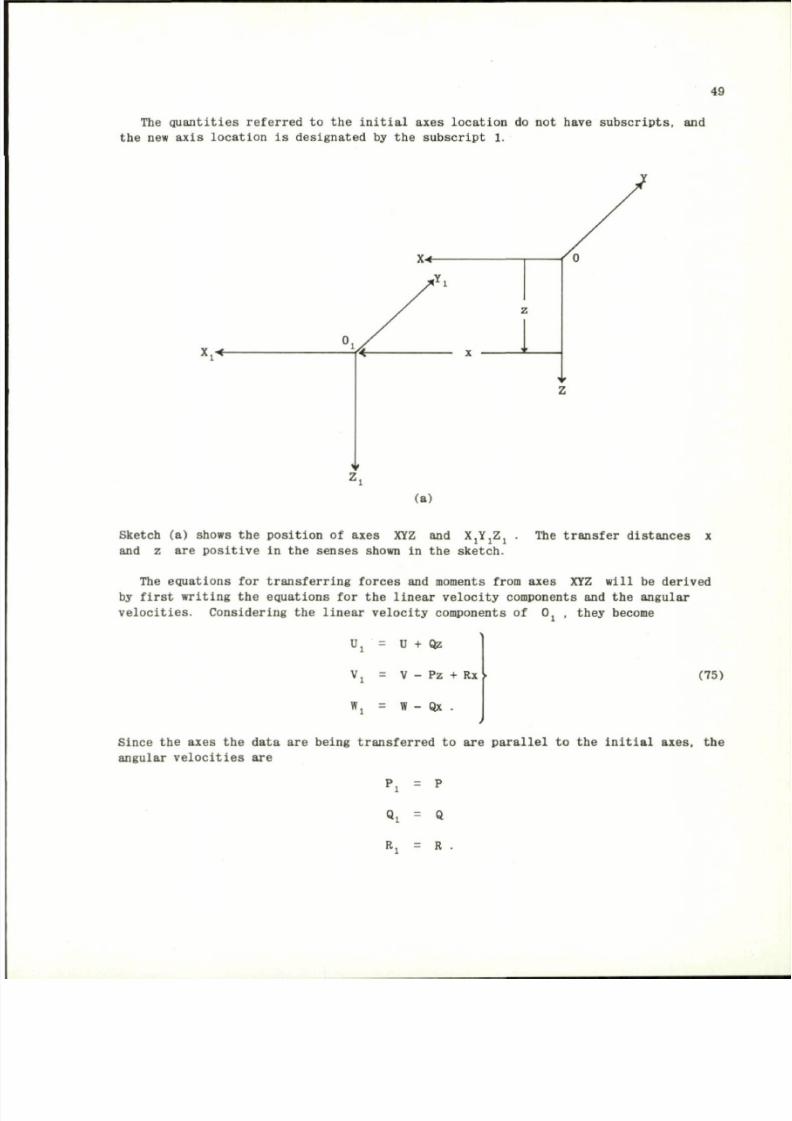
8/10/2019 Techniques for Measurement of Dynamic Stability Derivatives in Ground Test Facilities
http://slidepdf.com/reader/full/techniques-for-measurement-of-dynamic-stability-derivatives-in-ground-test 69/236
49
The quantities referred to the initial axes location do not have subscripts, and
the new axis locat ion is designated by the subsc ript 1.
X*-
(a)
Sketch (a) shows the position of axes XYZ and X J Y J Z J . The transfer dista nces x
and z are pos iti ve in the senses shown in the sketch.
The equations for transferring forces and mome nts from axes XYZ will be derived
by first writing the equations for the linear velocity components and the angular
velocities. Considering the linear velocity components of Oj . they become
U
= U + Qz
Vj = V - Pz + Rx
Wj = W - Qx •
(75)
Since the axes the data are being transferred to are parallel to the initial axes, the
angular velocities are
Pj = P
Qi = Q
R .
8/10/2019 Techniques for Measurement of Dynamic Stability Derivatives in Ground Test Facilities
http://slidepdf.com/reader/full/techniques-for-measurement-of-dynamic-stability-derivatives-in-ground-test 70/236
50
If
we let the
external forces
and
moments
for the
axes
XYZ be
designated
as (P„F P )
/ \ A y z
and ( M
X
H L M
Z
) , respectively, the moments are given as
M
X 1
= M
x
+ F
Y
Z
M
Y 1
= M
Y
+ F
z
x - F
x
z •
"Zi
M
z
- P
Y
x
(76)
The angular velocities
and
velocity components
of 0 and O j
parallel
to the
axes
for disturbed motion are given by
u
V
w
' l
-
=
=
=
U
0
+ u .
v .
W
0
+ w .
U
0 1
+ U
1 •
p
Q
R
P
:
=
=
=
=
P
0
+ P
Qo + q
R
0
+ r
p
o i
+ D
i
V
l = Vj
W
01
+
' l
Q
:
= V + Q,
Rj = R
0 1
+ rj
(77)
where
the
subscript
0
,
a s
used
for U
Q
, V
Q
, W
Q
, P
0
, 0 , . and R
Q
,
designates
the velocity components
o f th e
center
o f
gravity
and the
angular velocities
in a
reference steady-flight condition.
3 . 2 . 1 . 6 . 1 S t a b i l i t y D e r i v a t i v e s
The transformation equations
are
derived here
by
first expressing
the
force
and
moment component derivatives
in a
Taylor serie s expansion
and
employing
the
relation
ships derived for linear and angular velocities and forces and moments. It is con
venient here t o introduce the standard short form notation:
X,Y,Z, Components of the external forces
parallel to axes X , Y , Z .
L.M.N, Mome nts about axes
Y . Z
3 . 2 . 1 . 6 . 2 L o n g i t u d in a l S t a b i l i t y D e r i v a t i v e s
The general expansion of the aerodynamic force c omponents along the body X Z axes
and
the
pitchi ng moment
may be
expressed
as
follows:
X = X
0
+ X
u
u + X^u + X
q
q + X
q
q + X,w + Xj,w +
Z
= Z
Q
+ Z
u
u + Z-ii + Z
q
q + Z
q
q + Z,w + Z
;
w +
M
= M
Q
+ M
u
u + M^u + M
q
q + M^ q + M,w + M; w +
(78)
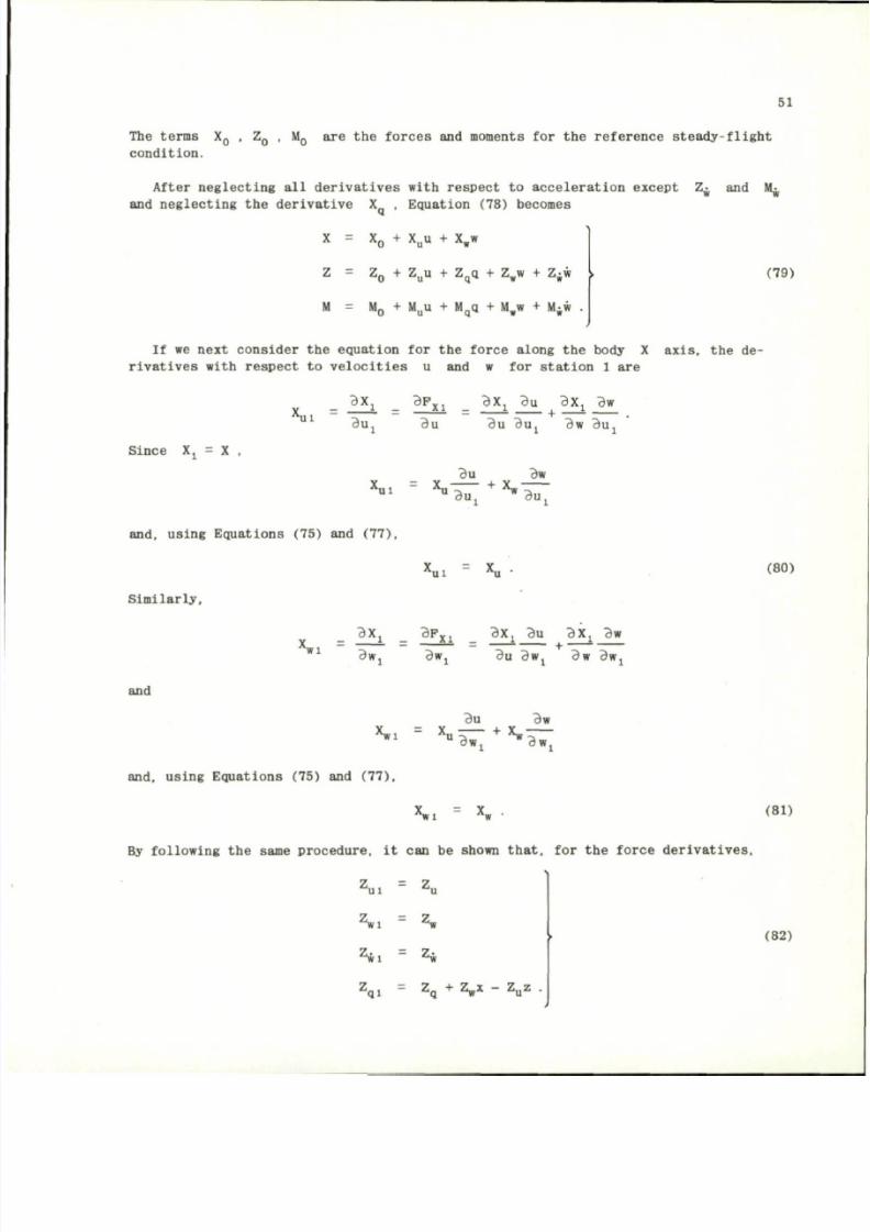
8/10/2019 Techniques for Measurement of Dynamic Stability Derivatives in Ground Test Facilities
http://slidepdf.com/reader/full/techniques-for-measurement-of-dynamic-stability-derivatives-in-ground-test 71/236
51
T h e t e r m s X
Q
, Z
Q
, M
Q
a r e t h e f o r c e s a n d m o m e n t s f o r t h e r e f e r e n c e s t e a d y - f l i g h t
c o n d i t i o n .
A f t e r n e g l e c t i n g a l l d e r i v a t i v e s w i t h r e s p e c t t o a c c e l e r a t i o n e x c e p t Z ^ a n d M ^
a n d n e g l e c t i n g t h e d e r i v a t i v e
X ,
E q u a t i o n ( 7 8 ) b e c o m e s
X = X
0
+ X
u
u + X
w
w
Z = Z
0
+ Z
u
u + Z
q
q + Z
w
w + Z ^ w [ (79)
M = M „ + M
u
u + M
q
q + M „ w + M
;
w .
I f w e n e x t c o n s i d e r t h e e q u a t i o n f o r t h e f o r c e a l o n g t h e b o d y X a x i s , t h e d e
r i v a t i v e s w i t h r e s p e c t t o v e l o c i t i e s u and w f o r s t a t i o n 1 a r e
V
U 1
B X j B P
X 1
B X J B U 3 X J BW
d u .
rtu
B u 3 u j B w B u j
S i nc e Xj = X ,
u I
Bu Bw
X u
l ) u T
+ X
* B u T
a n d , u s i n g E q u a t i o n s ( 7 5 ) a n d ( 7 7 ) ,
S i m i l a r l y ,
' u i
X
u
(80)
B X j B F
X 1
B X J Bu BX j Bw
X
w i
:
•*_ ~ ~
_
~ -
+
~
Bwj
Bw,
and
;
^u
Bu BWj Bw Bwj
ciw
X w l X u
B w
1
+ X
« B W j
a n d , u s i n g E q u a t i o n s ( 7 5 ) a n d ( 7 7 ) ,
x
w l
X
w
.
B y f o l l o w i n g t h e s a m e p r o c e d u r e , it c a n b e s h o w n t h a t , f o r t h e f o r c e d e r i v a t i v e s ,
Z
u i =
Z
u
Z
w 1
= Z
w
^ l
= Z
w
Z
q l =
Z
q
+
V "
Z
u
z
•
( 8 1 )
( 8 2 )
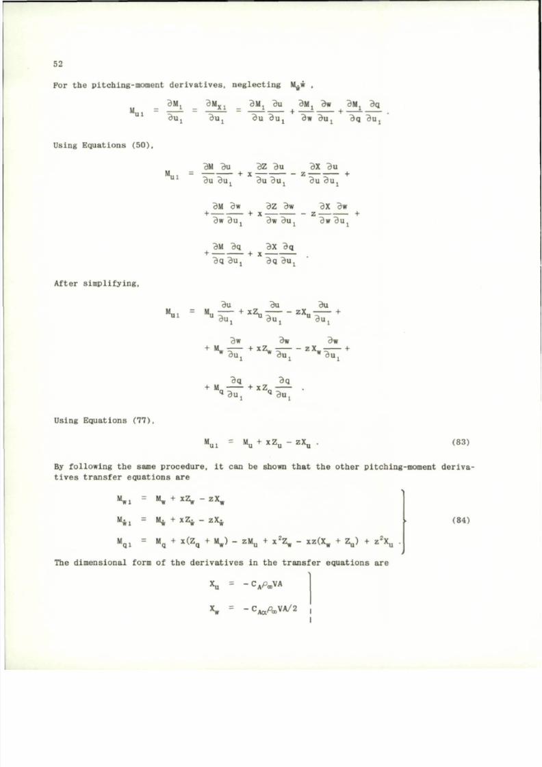
8/10/2019 Techniques for Measurement of Dynamic Stability Derivatives in Ground Test Facilities
http://slidepdf.com/reader/full/techniques-for-measurement-of-dynamic-stability-derivatives-in-ground-test 72/236
52
F o r t h e p i t ch in g - mo men t d e r i v a t i v e s , n eg l ec t i n g M w ,
BMj BM
X 1
B M J B U B M J B W B M J B q
M j . . - • — + — — - • + - -
B u, B U , B U B U , BW B U , B Q B U .
u B u j Bw Buj Bq Bu j
Us ing Equ at ion s (5 0) ,
"ui
BM Bu BZ Bu BX Bu
+ x - z ^ r — +
Bu Bu.
Bu Bu , Bu Bu ,
BM Bw BZ Bw BX Bw
+ + X z +
Bw B u, Bw Bu , Bw B u,
A f t e r s i mp l i f y i n g ,
BM Bq BX Bq
+ - - + x-
Bq Buj Bq Buj
M
ui
Bu Bu
+ x Z
u T - -
z X
u
Bu
i
A
w
Bu
Bu~
Bw
Bw Bw
+ M , — + x Z - z X
w
- — +
" Buj * Buj
w
Buj
Bq Bq
+ M
n
+ x Z
n
Q
B U j
q
B U j
Us ing Equat ions (77) ,
U l
% + ^ Z
u
"
z X
u
(83)
By fo l low ing th e same proc edu re , i t can be shown th a t t he o t he r p i t ch ing-moment de r iv a
t i v e s t r a n s f e r e q u a t i o n s a r e
M
wl
M
w i
M
w
+ x Z
w " zX
w
M*
+ x Z
w "
z X
w
M
q l
= M
q
+ x
<
Z
q
+
" * ) ~
z M
u
+ x
\ "
xz
<
X
w
+
*V
+ z
\ •
T he d i men s i o n a l f orm o f t h e d e r i v a t i v e s i n t h e t r a n s f e r e q u a t i o n s a r e
x
u = "CAPCOVA
* .
=
- C
A o t
^ V A / 2 j
(84)
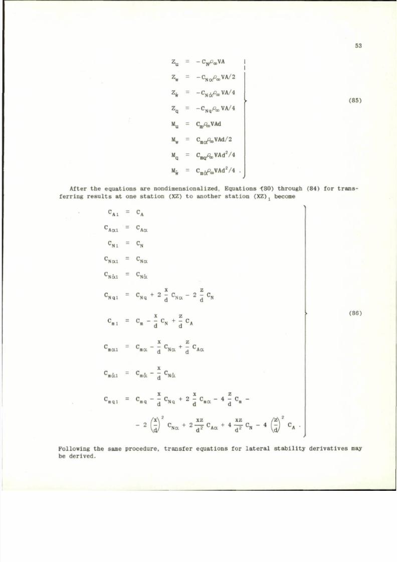
8/10/2019 Techniques for Measurement of Dynamic Stability Derivatives in Ground Test Facilities
http://slidepdf.com/reader/full/techniques-for-measurement-of-dynamic-stability-derivatives-in-ground-test 73/236
53
Z
u
=
-C
N
PooVA
Z
w = -
C
N a ^ V A / 2
Z
w = -C
N 6 t
P » V A / 4
Z
q = - < W « , V A / 4
M
u
= C ^ V A d
"w =
C
m c A
V A d / 2
% = C
m q
Pa
)
V A d
2
/4
M
w = C
m
^ a , V A d
2
/ 4
(85)
After the equations are nondimensionalized, Equations <80) through (84) for trans
ferring resu lts at one station (XZ) to another station (XZ) become
'A;
C
A a i
C
A a
'Nl
'Nai ^Na
'Nai
C
N a
X z
:
N Q I
C
N q
+ 2
^
C
N a ~
2
d °
N
J
m
1
m
d
N
d
A
X Z
C
»a i
C
» a "
d
C
N a
+
d
C
A a
c
m d i =
c
mo.
J
Na
'nql
X X z
C
m q " Z
C
N q
+ 2
"1
C
m a "
4
Z
C
m "
- 2
x\
2
XZ
5 J
C
a
+
»
7
XZ
C
A a
+ 4
T J
C
N "
4
c
A
•
(86)
Following the same procedure, transfer equations for lateral stability derivatives may
be derived.
8/10/2019 Techniques for Measurement of Dynamic Stability Derivatives in Ground Test Facilities
http://slidepdf.com/reader/full/techniques-for-measurement-of-dynamic-stability-derivatives-in-ground-test 74/236
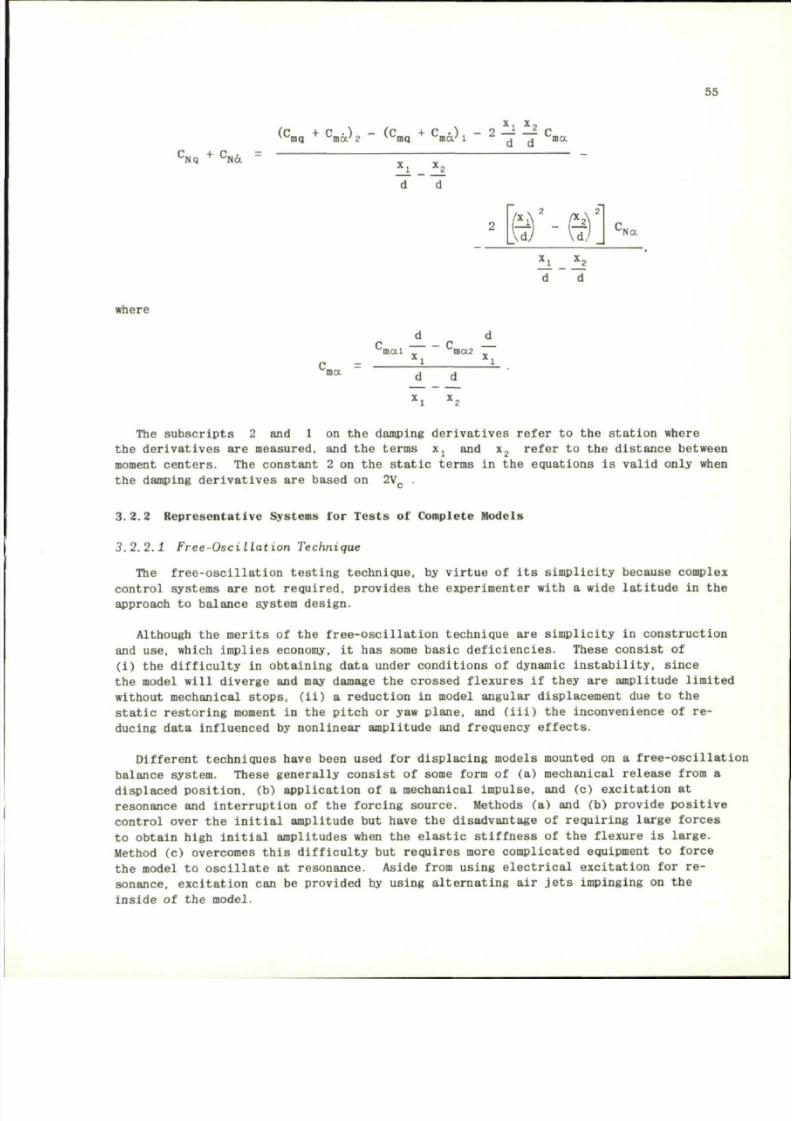
8/10/2019 Techniques for Measurement of Dynamic Stability Derivatives in Ground Test Facilities
http://slidepdf.com/reader/full/techniques-for-measurement-of-dynamic-stability-derivatives-in-ground-test 75/236
55
(
C
mq
+
C
md^ 2 " ^
C
m q
C
ma'
1
2
7 7
C
ma
C
Nq
+ C
N a
d d
where
ma
\ d ) Vd,
'Na
d d
r > _ c
mai
ma2
*i
x
i
The subscripts 2 and 1 on the damping derivatives refer t o t h e station where
the derivatives are measured, and the terms Xj and x
2
refer t o t h e dista nce between
moment centers. T h e constant 2 on the static terms in the equations is valid only when
the damping der ivatives a r e based on 2V
C
.
3.2.2 Represe ntative Syste ms for Tests o f Complete Models
3 . 2 . 2 . 1 F r e e - O s c i l l a t i o n T ec hn iq ue
The free-osc illation testing technique, by virtue o f i t s simplicity because complex
control systems are not required, provid es t h e experimenter with a wide la titude in the
approach
to
bala nce system design.
Although the merits o f t h e free-o scillat ion tec hnique are simplicity in construction
and use, which implies economy, i t h a s some basic deficie ncies. These consist of
(i ) th e difficulty in obtaining dat a under conditions o f dynamic instability, since
the model will diverge and may damage the crossed flexures if they are amplitude limited
without mechanical stops, (ii) a reduction in model angular displac ement d u e t o t h e
static restoring moment in the pitch o r y aw plane, and (iii) the inconvenience of re
ducing da ta influenced
by
nonlinear amplit ude
and
frequency effects.
Different techniques have been used for displaci ng mo dels mounted on a free-oscillation
balance system. These generally consist of some form of (a) mechanical release from a
displaced position,
(b)
application
of a
mechanical impulse,
and (c)
excitation
at
resonance and interrupti on o f t h e forcing source. Methods (a) and (b) provide positive
control over t h e initial amplitud e but have t h e disadvantage of requiring large f orces
to obtain high initial amplitudes when the elastic stiffness o f t h e flexure is large.
Method (c) overcomes th is difficulty but requires more complica ted equipment to force
the model
to
oscillate
at
resonance. Aside from using electrical excitation
for re
sonance,
excitation can be provided by using alternating air jets impinging on the
inside o f t he model.
8/10/2019 Techniques for Measurement of Dynamic Stability Derivatives in Ground Test Facilities
http://slidepdf.com/reader/full/techniques-for-measurement-of-dynamic-stability-derivatives-in-ground-test 76/236
56
Many free-oscillation dynamic stability balance systems have evolved in the United
States and in NATO countries to obtain information experimentally for support of vehicle
development and theoretical studies. To show the basic features of most of the systems
in current use, examples of some systems will be described which are designed with
crossed-flexure pivots, and gas bearing pivots.
To perform dynamic stability tests at Mach numbers from 18 to 21 in the AEDC-VKP
100 in. diameter hypervelocity tunnel (Tunnel F ) , which has a useful run duration of
about msec, a high frequency, fre e-oscillat ion balance system is used. To obtain up
to about 15 cycl es of data during a run, high mo del frequencies, mi nimum inertia models ,
and high crossed -flexure stif fness are required. A flexure system which provid es a
model frequency o f 150 c/s at oscill ation amplitude s up to ± 3 degrees is shown in
Figure 43 (Ref.47).
To displac e the pivot to an initial am plitude a couple rathe r than a moment is used
to minimize a beat oscillation that would be imposed on the oscillation envelope and
reduce the total stress experienced by the pivot.
In operation, the model and pivot system is displaced to a desired amplitude by the
pneumatic operation of two displacement arms which apply a couple about the pivot axis.
Once the desired amplitude is reached, two cams operated by the releasing piston make
contact with the displacement arms and instantaneously release the applied couple.
A low-frequency, free-oscillation, flexure pivot balance system also in use in the
AEDC-VKF is shown in Figure 44 to ill ustrate the sim plicity of the design and a method
for displacing the model. Two jets located 180 deg apart are mounted to the sting
just inside of the model base and are alternately supplied with high pressure air
through an oscillat ing servo valve.
Forces generated by impingment of the jets on the inside of the model cause the
model to oscillate. Amplitud e is controlled by the jet pressure, and frequency is
controlled by the servo valve. The model may be forced to oscillat e at its natural
frequency and when the required amplitude is achieved the air excitation is terminated
and the model is free to oscillate.
A free-oscillation flexure pivot system developed by ONE RA"
5
is shown in Figure 45
to illustrate a mechanical system for displacing the mode l. For most flexure pivot
balance systems, strain gages are bonded to the cross flexures to provide a signal
output for recording the amplitude time history and model oscillation frequency.
Free-oscillation balance systems, having either ball bearings or gas bearings for
the pivot , may not have mechanical s tiffness to provide a restoring moment. For these
systems the model is displaced by a mechanical system and released. If the tunnel has
a model injection system, the model can be preset to the required amplitude, locked,
and then released af ter injection into the airstrea m. An example of an AED C-VKP free-
oscillat ion ba lance system used in this mo de is shown in Figure 46.
Most of the free-oscillation balance systems described thus far have been developed
for use in relatively small wind tunnels. A free-oscillation balance developed by
the AE DC-PWT (Ref.49) for tests in the 16 ft transonic and supersonic t unnels is shown
in Figure 49. The bala nce has a single vertical flexure in the center and two longi
tudinal flexures at the sides for a pivot. A hydraulic mechanism is provided for
8/10/2019 Techniques for Measurement of Dynamic Stability Derivatives in Ground Test Facilities
http://slidepdf.com/reader/full/techniques-for-measurement-of-dynamic-stability-derivatives-in-ground-test 77/236
57
initially displacing the flexure and model , and a hydraulic cylinder provides a means
for locking the system. Strain gages on the flexures are used to obtain a measure of
the amplitude decay history.
A free-oscillation dynamic balance system has been developed by the University of
California Institute of Engineering Research to measure dynamic stability derivatives
in a low density wind tunnel
50
. Figure 50 shows the components of the balance system.
The model is mounted on a transverse rod supported in the vertical p lane by bearings.
The bearings have an electrically vibrated inner bearing race to minimize the friction
and provide repeat able bearing tares. System restoring moment is provided by a quartz
fiber attached to the tip of the transverse rod support. A cross shaft is mounted on
the end of the transverse rod support to displace the model by the use of an electro
magnet and also interrupt a beam to a photoce ll. One arm casts a shadow on a screen
to provide direct oscillation angle measurements.
A small scale, free-oscillation, dynamic balance developed by the AEDC-VKF for tests
in a small low density tunnel is shown in Fig ure s 51 and 52. The com merci al flexure
pivot is 0.125 in. in diameter. The fixed portion of the pivot is supported by two
supports, and the movable center portion of the flexure is clamped in the balance
centerpiece. As the movab le member is rotated, the air gap between it and the E-core
changes to produce a change in signal level proportional to the angle.
Angular position histo ries for the g as bearing pi vots are recorded with the E-core
transducer described in Section 3.2.2.1. Aerodynamic damping from a free-oscil lation
system is obtained thro ugh an analysis of the record of motion recorded on magnetic
tape,
film, or oscillo graph re cordings to obtain the logarithmic decrement. Reduct ion
of the data from a magnetic tape may be accomplished with a high speed computer to
curve fit the motion data, read the peak amplitudes, and finally curve fit data in the
form of log of the amplitude versus cycles of oscillation. If the data are recorded
on film or an oscillograph, many manual operations are involved which are tedious and
reduce the accuracy of the data reduction.
The ablation of a vehicle' s thermal protect ion system can result in motions which
have a significant effect on the vehicle performance. Study of these effects experi
mentally has been somewhat restricted because present capabilities of wind tunnel
facilities do not provid e a complete dupli cation of re-entry flow conditions. Ablation
affects dynamic stability primarily by changes in body shape, mass distribution, and
the mixing of gaseous produ cts of ablation with the boundary layer. At the present
time,
study of the effects of ablation have proceeded along the lines of using low
temperature ab lators and poro us model blowing techniques. This is desirabl e in a
study of shape change and its effects on stability; however, the results have limited
application for important paramet ers such as material proper ties and phase angle.
Mass addition, on the other hand, offers possibilities for simulating many of the
important par amete rs and enables measurement and systematic v ariation of these parameters.
Some of these parameters include mass injection rate, distribution, phase, wave form,
gas propert ies, and frequency of osci llation.
LTV has pioneered the development o f techniques and equipment to investigate the
effects that mass addition, through porous models, has on dynamic stability. These
investigations have been conducted in the LTV hypervelocity wind tunnel, which is a
modified h otshot -type facility with relat ively long run tim es (250 millis econds at
8/10/2019 Techniques for Measurement of Dynamic Stability Derivatives in Ground Test Facilities
http://slidepdf.com/reader/full/techniques-for-measurement-of-dynamic-stability-derivatives-in-ground-test 78/236
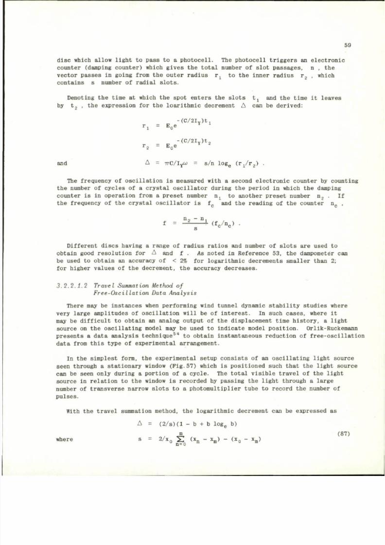
8/10/2019 Techniques for Measurement of Dynamic Stability Derivatives in Ground Test Facilities
http://slidepdf.com/reader/full/techniques-for-measurement-of-dynamic-stability-derivatives-in-ground-test 79/236
59
disc which allow light to pass to a photocell. The photocell triggers an electronic
counter (damping co unter) which giv es the total number of slot passa ges, n , the
vector passes in going from the outer radius r
:
to the inner radiu s r
2
, which
contains s number of radial slots.
Denoting the time at which the spot enters the slots tj and the time it leaves
ithmlc dec
(C/2I
y
)tj
by t
2
, the expression for the loarit hmic decrement A can be derived:
r
i =
E
o
e
-(C/2I
Y
)t
r
2
= E
0
e
and A = T T C / I ^ O = s/n log
e
(rj/r
2
) .
The frequency of oscillation is measured with a second electronic counter by cou nting
the number of cycles of a crystal oscilla tor during the period in which the damping
counter is in operat ion from a preset number n
x
to another preset number n
2
. If
the frequency of the crystal oscillator is f
c
and the reading of the counter n
c
,
n, — n,
f = - 2 - ^ - 4 ( f
c
/n
c
) .
Different di scs having a range of radius ratios and number of slots are used to
obtain good resolutio n for A and f . As noted in Refere nce 53, the dampometer can
be used to obtain an accuracy of < 2% for logarithmic decrements smaller than 2;
for higher va lues
of the
decrement,
the
accuracy decreases.
3 .2 .2 .1 .2 Tra vel Summation Method of
F r e e - O s c i l l a t i o n D a t a A n a l y s i s
There may be instances when performing wind tunnel dynamic stability studies where
very large amplitudes of oscilla tion will be of interest. In such cases, where it
may be difficult to obtain an analog o utput of the displacement time history, a light
source on the oscillating model may be used to indicate model positio n. Orlik-Ru ckemann
presents a data analysis tec hnique
5
" to obtain instantaneous r eduction of free-oscillation
data from this type of experimental arrangement.
In
the
simplest form,
the
experimental setup c onsists
of an
oscillating light source
seen through a stati onary window (Pig .57) which is positioned such that the light source
can be seen only duri ng a portion of a cycle. The total visible travel of the light
source
in
relation
to the
window
is
recorded
by
passing
the
light through
a
large
number of transverse narrow slots to a photomultiplier tube to record the numbe r of
pulses.
With the travel summation method, the logarithmic decrement can be expresse d as
A = (2/s)(l - b + b l o g
e
b)
m
(87)
where s = 2/x
0
S (
x
n
~
x
m ) (
x
o
x
m
)
n= o
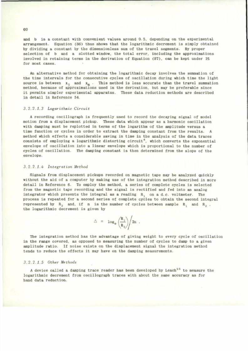
8/10/2019 Techniques for Measurement of Dynamic Stability Derivatives in Ground Test Facilities
http://slidepdf.com/reader/full/techniques-for-measurement-of-dynamic-stability-derivatives-in-ground-test 80/236
60
and b is a constant with c onvenient va lue s arou nd 0.5, depending on the experimental
arrangement. Equation (86) thus shows that
the
logarithmic decrement
is
simply obtained
by dividing
a
constant
by the
dim ensionless
sum of the
travel segments.
By
proper
selection of b and a slotted window, the total error, including the approximat ions
involved
in
retaining te rms
in the
derivation
of
Equation (87),
can be
kept under
1%
for most cases.
An alternative method
for
obta ining
the
logarithmic decay involves
the
summation
of
the time intervals
for the
consecutive cycles
of
oscill ation d uring which time
the
light
source
is
between
x
0
and x
m
. This method
is
less accurate than
the
travel summation
method, because of approximations used in the derivation, but may be preferable since
it permits simpler experimental apparatus. These data reduction methods are described
in detail
in
Reference
54.
3. 2. 2. 1. 3 Logarithmic Cir cui t
A recording oscillograph
is
frequently used
to
record
the
decayi ng signal
of
model
motion from a displacement pickup. These data which appear as a harmonic oscillati on
with damping must
be
replotted
in
terms
of the
logarithm
of the
amplitude versus
a
time function
or
cycles
in
order
to
extract
the
damping constant from
the
results.
A
method which effects
a
considerab le saving
in
time
in the
analysi s
of the
data traces
consists of employing a logarithmic distorting circu it
6
, which converts the exponential
envelope of oscil lation into a linear e nvelope which is proportional to the number of
cycles
of
oscillation.
The
damping constant
is
then deter mined from
the
slope
of the
envelope.
3.2 .2. 1.4 In te gra ti on Method
Signals from displacement pic kups recorded
on
magnetic tape
may be
analyzed quickly
without
the aid of a
computer
by
making
use of the
integration meth od described
in
more
detail
in
Reference
6. To
employ
the
method,
a
series
of
complete cycles
is
selected
from the magnetic tape recording and the signal is rectified and fed into an analog
integrator which presents the integral as a reading Rj on a d.c. voltmeter. The
process
is
repeated
for a
second serie s
of
complete cycles
to
obtain
the
seco nd Integra l
represented
by R
2
and, if n is the
number
of
cycle s between sam ple
Rj and R
2
.
the logarithmic decrement is given by
The integration method
has the
advantage
of
giving weight
to
every cycl e
of
oscillation
in the range covered, as opposed to measuring the number of cycles to damp to a given
amplitude ratio. If noise exists on the displa cement signal the integration method
tends
to
reduce
the
effects
it may
have
on the
damping measurements.
3.2.2.1.5 Other Methods
A device called
a
damping trace reader
has
been d evelope d
by
L e a c h
55
to
measure
the
logarithmic decrement from oscillograph traces with about the same accuracy as for
hand data reduction.
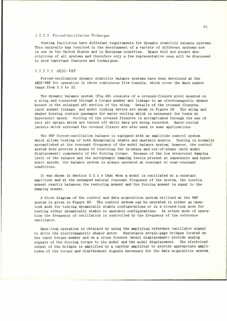
8/10/2019 Techniques for Measurement of Dynamic Stability Derivatives in Ground Test Facilities
http://slidepdf.com/reader/full/techniques-for-measurement-of-dynamic-stability-derivatives-in-ground-test 81/236
61
3 . 2 . 2 . 2 F o r c e d - O s c i l l a t i o n T e ch n iq u e
Testing facilities have different requirements
for
dynamic stability balance systems.
This naturally
h a s
resulted
in the
development
o f a
variety
o f
different systems
now
in
use in the
United States
and in
Europe an countries. Space will
no t
permit
des
criptions
of all
systems
and
therefore only
a few
represe ntative ones will
be
discussed
to show important features
and
techniques.
3.2.2.2.1 AEDC-VKF
Forced-oscillation dynamic stability balance systems have been developed
at the
AEDC-VKF
for
operation
in
three c ontinuous flow tunnels, which cover
the
Mach number
range from
1.
5
to 12.
The dynamic balance system (Fig.58) consists
o f a
crosse d-flexure pi vot mounted
on
a sting
and
connected through
a
torque mem ber
and
linkage
to an
electromagnetic shaker
housed
in the
enlarged
aft
section
o f t h e
sting. Detai ls
o f t h e
crossed flexures,
input moment linkage,
and
model locking device
are
shown
in
Figure 59.
T h e
sting
and
shaker housing contain passages
for
water cooling which
is
necessary
for
tests
at
hypersonic speed. Cooling
o f t h e
crossed flexures
i s
accomplished through
t h e u s e o f
cool
air
sprays which
are
turned
off
while data
are
being recorded. Water-cooled
jackets which surrou nd
t he
crossed flexure
are
also used
in
some applications.
The
VK F
forced-o scillatio n balance
i s
equipped with
an
amplitude control system
which allows testing
o f
both dynamically stable
and
unstable model s. Testing
i s
normally
accomplished
a t t h e
resonant frequency
o f t h e
model balance system; however,
t h e
control
system does prov ide
a
means
o f
resolving
t he
in-phase
and
out-o f-pha se (with model
displacement) components
o f t h e
forcing torque. Because
o f t h e l ow
structural damping
level
o f t h e
balance
and the
aerodynamic damping levels present
at
supersonic
and
hyper
sonic speeds,
t he
balance system
i s
always operated
at
resonant
or
near-resonant
conditions.
It
was
shown
in
Section
3.2.1.4
that when
a
model
is
oscillated
at a
constant
amplitude
and at the
undamped natura l resonant frequency
o f t h e
system,
t h e
inertia
moment exactly balances
t h e
restoring moment
and the
forcing moment
is
equal
t o t h e
damping m oment.
A block diagram
o f t h e
control
and
data acquisition system utilized
at the VKF
system
is
given
in
Figu re 60.
T h e
control system
can be
operated
in
either
an
open-
look mode
for
testing dynamically stable configurations
or in a
closed-loop mode
for
testing either dynamically stable
o r
unstable configurations.
In
either mode
o f
opera
tion
the
frequency
o f
oscillation
is
controlled
by the
frequency
o f t h e
reference
oscillator.
Open-loop operation
is
obtained
by
using
the
amplified refere nce oscillator signal
to drive
t he
electromagnetic shaker motor. Resista nce strain-gage bridge s located
on
the input torque member
and on a
cross flexure (model displa ceme nt) provi de analog
signals
o f t h e
forcing torque
t o t h e
model
and the
model displace ment.
T h e
electrical
output
o f t h e
bridges
is
amplified
by a
carrier amplifier
t o
provide appropriate ampli
tudes
o f t h e
torque
and
displacement signals necessary
for the
dat a a cquisition system.
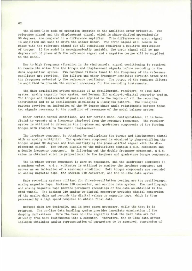
8/10/2019 Techniques for Measurement of Dynamic Stability Derivatives in Ground Test Facilities
http://slidepdf.com/reader/full/techniques-for-measurement-of-dynamic-stability-derivatives-in-ground-test 82/236
62
The closed-loop mode of operation operates on the amplified error principle. The
refere nce signal and the displace ment s ignal, which is phase -shif ted approximately
90 degr ees, are compared in a differ ence amplifier. This difference or error signal
is amplified and used to drive the shaker motor. The error signal will remain in
phas e with the refer ence signal for all conditio ns requiring a positi ve app lication
of torque. If the model is aerodynamically unstable, the error signal will be 180
degree s out of phase with the reference signal and a negative to rque will be supplied
to the model.
Due to h igh frequency vib rati on in the wind
tunnels,
signal co nditioning is required
to remove the noise from the torque and displacement signals before recording on the
dat a acquisition system. Two bandpass filters tuned to the frequency of the reference
oscillator are provided. The filters and other frequency-sensitive circuits track with
the frequency selected by the reference oscillator. The output of the bandpass filters
is amplified to provide the current necessary for the recording instruments.
The data acquisition system consists of an oscillograph, resolvers, on-line data
system, analog magnetic tape system, and Beckman 210 analog-to-digital converter system.
The torque and displacement signals are applied to the inputs of all the recording
instruments and to an oscilloscope displaying a Lissajous pattern. The Lissajous
pattern provides an indication of the 90 degree phase angle relationship between these
two signals necessary to the condition of resonance of the model balance system.
Under cer tain tunnel condit ions, and for certain model configu rati ons, it is bene
ficial to operate at a frequency displace d from the resonant frequency. The resolver
system is utilized to determine the in-phase and quadrature components of the forcing
torque with respect to the model displacement.
The in-phase component is obtained by multiplying the torque and displacement signal
with an analog multiplier. The quadrature component is obtained by phase-shifting the
torque signal 90 degrees and then multiplying the phase-shifted signal with the
dis
place ment signal. The output signals of the mult ipli ers contain a d.c. component and
a double frequency component. By filtering out the double frequency component, a d.c.
valu e is obtained which is prop orti onal to the in-phase and quadratu re torque components.
The In-phase torque component is zero at resonance, and the quadrature component is
a maximum value. A d.c. voltmete r is utilized to monitor the in-phase component and
serves as an indication of a reso nance condition. Both torque compo nents are recorded
on analog magnetic tape, the Beckman 210 converter, and the on-line data system.
Data recording systems utilized for forced-oscillation testing are the oscillograph,
analog magnetic ta pe, Beckman 210 converter, and on-line data system. The osci llogr aph
and analog magnetic tape p rovide permanent recordings of the dat a as obtained in the
wind tunnel. The Beckman 210 analog-to-dig ital converter provi des digital conversion
of the analog data and records the digital values on magnetic tape, which is then
processed by a high speed computer to obtain final data.
Reduced data are desirable, and in some cases necessary, while the test is in
progress.
The on-line data handling system provides immediate examination of the
damping derivatives. Here the term on-line signifies that the test data are fed
directly from test instruments into a computer. Therefore, the on-line data system
includes obtaining analog representation of par ameters to be measured, conversion of
8/10/2019 Techniques for Measurement of Dynamic Stability Derivatives in Ground Test Facilities
http://slidepdf.com/reader/full/techniques-for-measurement-of-dynamic-stability-derivatives-in-ground-test 83/236
8/10/2019 Techniques for Measurement of Dynamic Stability Derivatives in Ground Test Facilities
http://slidepdf.com/reader/full/techniques-for-measurement-of-dynamic-stability-derivatives-in-ground-test 84/236
64
3.2.2.2.3 NASA-LRC
The forced-oscillation balance system used by NASA-LRC is shown in a exploded and
assembled view
in
Figure 65. Sketches
of the
balance system
are
presented
in
Figures
66
a nd
67. Sinusoidal, constant-amplitude motion about
an
oscilla tion axis
is
produced
by
a
mechanical Scotch yoke
and
crank which
is
driven
by a
variable-f requency electric
motor in the downstrean porti on o f t h e sting. The stiff strai n-gaged beam located
between t he model attachment bulkhead and pivot axis i s used to measure the forcing
moment required
t o
oscillate
t he
model. Because
of its
location
the
signal output
i s
not Influenced
by the
friction
or
mechanical play
in th e
system. Model displaceme nt
is measured with a strain-gaged cantilever beam mounted be tween the fixed sting and
the oscillating model support. Springs of different stiffnesses are used to provide
a range
of
resonant frequencies.
Outputs from
the
displacement
and
forcing-moment strain gages pas s through coupl ed
sine-cosine resolvers which
are
geared
to the
drive shaft
and
thus rotate
at the
funda
mental drive frequency
(Pig.66).
Oscilla tion frequency
i s
measur ed with
a
signal genera
tor coupled to the drive shaft. In operation t h e resolvers transform the moment and
amplitude functions into orthogonal components which
are
measured with d.c. micro-
ammeters. From these components
t he
resultant applied moment, displacement,
and
phase
angle are found and, with th e oscil latio n frequency, t h e aerodynamic static and damping
moments are computed. A block diagram of the electro nic ci rcuit used to measure t h e
applied moment
is
shown
in
Figure
68 and a
similar circuit
is
used
to
measure
the
angular displacement.
Use is made of automatic digital equipment to acquire data quickly and eliminate
operator errors due to incorrect manual recordi ng or reading. All of the system var i
ables
are
automatically digitized,
and a
high speed computer
is
used
to
perform
the
data reduction
and
present results
in
coeffi cient form.
A complete description
o f t h e
system electrical relations
and
metho ds involved
in
the operation
and
data reduction
are
found
in
References
59 and 60.
3.2.2.2.4 RAE-Bedford
The forced-oscillation testing technique ha s been employed by the RAE, Bedford, i n
the development of a system for measuring stability de rivatives and damping derivatives
due
to
angular v elocity
in
roll
and ya w on
sting-mounted m od el s
62
. Derivatives
can be
obtained
for
motion
in
vertical
or
horizontal tr anslation (heave
or
sideslip); however,
it
is
noted
in
Reference
62
that
t he
apparatus
was not
designed
for
this purpose
and
the accuracy
of the
measurements
is
less than that required
for
most tests. Emphasis
in t he design h a s been toward a small s ize system that can be used for testing slender
wings
o f
fiber glass construction.
In some respects
the
balance system
is
similar
to
those described
in
Section
3.2.2.1
in that the model is mounted on a sting by means o f a flexure pivot allowing one degree
of freedom in rotation. Continuous excitation at or near the resonant frequency of
the system
is
provided
by a
movi ng-coil per manent-magnet vibr ation generator mounted
on
t h e
sting
and
coupled
to a
driving
rod
passing through
th e
sting.
A schematic arrangement
of
various p arts
of the
balance
for
yaw-sideslip oscillation
is shown
in
Figur e 69.
The
balance
is
mounted
on the end of a
sting
by
means
o f a
8/10/2019 Techniques for Measurement of Dynamic Stability Derivatives in Ground Test Facilities
http://slidepdf.com/reader/full/techniques-for-measurement-of-dynamic-stability-derivatives-in-ground-test 85/236
65
flexure pivot to allow rotation. A view of the flexure pivot and cylindrical section
of the balance which mounts inside of the model is shown in Figure 69, and photographs
are presented in Figure 70. Included in the flexure pivot as sembly is the drive linkage
to convert the longitudinal force in the driving rod into a couple acting between the
end of the sting and the model.
The balance for measuring oscillation in roll is illustrated schematically in Figure
69.
The unit is of one-piece constructio n and is instrumented with ya w and roll
accelerometer s. The system has one degree of freedom, and excitation in roll is
pro
vided by applying torque through the driving rod by means of linkage from the vibration
generator.
Although the flexure pivot i s located near the center of pressure of the wing models,
in order to avoid large deflections under steady aerodynamic
loads,
the flexibility of
the sting will allow some translation of the pivot axis which may be appreciable for
some cases. To allow for displacement of the pivot
axis,
for example, when measuring
pitching derivat ives, heaving derivati ves are measured by exciting a vertica l oscilla
tion (which will be accompanied by some angular movement) and measuring the changes
in natural frequency, excitation force, and angular movement.
The motion of the model on the balance system consists of a pitching component,
generated in part by the rotation of the model about the flexure pivot and in part by
the bending of the end of the sting. These two compo nents are present in different
proporti ons in the two natural mod es of the system. The pitching mode includes a
certain amount of heave motion of the pivot axis, and the heave mode includes an
appreciable amount of pitching motion and similarly for yaw and sideslip.
As was noted in Reference 62, it may not be ob vious ho w an exciting coupl e acting
between the model and the end of the sting can produ ce no deflection. The reason Is
that in the natural mode of oscillation in heave, for example, there is a certain
amount of rel ative angular movement between the model and the end of the sting (even
when there is no pitching component in the oscillation). It is thus possib le for the
excitation couple to feed energy into the system in this
model.
The analysis of the system is simplified by treating the system as having two degrees
of freedom with two natural modes of vibration - one predominantly pitching and the
other predominantly heaving. The heaving derivatives appear as a by-product of the
analysis to obtain the damping-in-pitch derivati ves. Yawing deriva tives are measured
in the same manner, with sideslip derivatives appearing as a by-product.
The basic measurem ents made with the balance system include (i) the excitation
frequency which is measured by an electronic counter, (ii) the excitation force which
is measured in ter ms of the exciter current, and (iii) the bala nce displace ments which
could be obtained as measurements of strains or relative displacements; accelerometers
were selected for the design since they are not affected by steady loads and are com
paratively free from interactions.
The balance is designed (Fig.
70)
with strain gages mounted on sections for measuring
static forces and moments, except for rolling moment which is more conveniently measure d
with the flexure unit designed for roll oscillations.
8/10/2019 Techniques for Measurement of Dynamic Stability Derivatives in Ground Test Facilities
http://slidepdf.com/reader/full/techniques-for-measurement-of-dynamic-stability-derivatives-in-ground-test 86/236
66
The automatic measuring and recordi ng equipment developed by the RAE for experim ents
concerned with oscillatory der ivative i s a digital amplitude and phase measuring system
(DAPHNE). It was
designed
to use the
wattmeter metho d
6
to
resolve
the
input signals
into in-phase
and
quadrature components,
and
accurate measurements
of
fr equency
are
made with
an
electro nic counter.
3 . 2 . 2 . 2 . 5
NASA-ARC
A method
and a
balance system
is
described
in
Reference
63 for
measuring
th e
lateral
and dynamic stability derivatives. The features o f t he system include single- degr ee-
of-freedom osc illations which are used to obtain comp onents o f pitch, yaw, and roll by
varying
the
axis
o f
oscillation. Amplitude control
i s
achieved with
a
velocity feedback
loop. T h e
system
is
equipped with
a
system
of
strain gage data proc essing
in
which
electronic analog computer elements are used in measuring the amplitude and phase
position. Moment derivatives which arise from angular motions can be measured with
the balance system. These include
t h e
rotary damping derivativ es
C , C + C • ,
and
C
n r
- C
n/
3 ; th e
cross derivatives
C a nd C j
r
- Cji ; and the
displacement
derivatives
C
m a
, C ^ and C
; / 3
.
The forced-oscillation system has two oscillation mechanisms - one for pure pitching
or yawing motion in which t he oscillation axis is perpendicular to the longitudinal
axis
of the
sting,
and one for
combined rolling
and
pitching
or
rolling
and
yawing
in
which
the
axis
o f
oscillation
is
inclined
45
degrees
t o t h e
longitudinal axis
of the
sting. T h e electromagnetic shaker is housed in an enlarged section o f t h e sting down
stream o f the model and connecte d to the flexure pivo ts b y push rods. Strain gages
were used
to
measure
t h e
oscillation amplitude
and
supply Inputs
to the
analog com puter.
The theory of the system ope ration, feedback control, analog compu ting system,, and
description
of the
apparatus
is
presented
in
Reference
63.
3 . 2 . 2 . 2 . 6 U n i v e r s i t y o f M i ch ig a n
Results obtained at hypersonic and hypervelocity speeds have shown the importance
of the reduce d frequency of oscill ation. With the use of the free-o scillat ion testi ng
technique, the
frequency
of
oscillation
can be
varied only
by
changing either
the
moment
of
inertia
or the
flexure spring constant. Thus coverage
o f a
wide range
of
frequencies requires several time-consuming changes
in the
test equipment.
The University
of
Michigan
h a s
developed
an
electromagnetic, forced-oscillation
method which enables a range o f oscillation frequencies to be investigated with e ase
6
".
The method utilizes
the
principle
of the
moving coil galvanometer.
An
alternating
current,
passing through
a
coil embedded within
th e
test model, interacts with
a
static
magnetic field imposed
by a
coil system mo unted
in one
plane
of the
test section. This
causes
the
model
to
oscillate
in a
sinusoida l manner following
the
existing torque
but
out o f phase with it. From the phase lag of the motion relative to the existing moment
and wind-on and wind-off result s, it is possible to determine the aerody namic damping.
A schematic view o f t he test setup showing t h e external coil is presented in Figure
71. A
circular exciter coil
wa s
mounted coaxially within
t he
Plexlglas model which
was
mounted on a cruciform flexure pivot shown in Figure 72.
8/10/2019 Techniques for Measurement of Dynamic Stability Derivatives in Ground Test Facilities
http://slidepdf.com/reader/full/techniques-for-measurement-of-dynamic-stability-derivatives-in-ground-test 87/236
67
The methods have been used
for
measuring
t he
position
o f t h e
model.
One of the
methods utilized
t h e
output
of the
strain gage bridge shown
in
Figure
72 and the
other
was based
on the
response
of a
second circula r coil within
t he
exciter coi l located
in
the model.
A s t h e
model oscillates
in the
magnetic field,
an
electromotive force
is
induced
in the
secondary coil
and may be
used
for
sensing
the
cone position. Although
this technique
h a s
been success ful,
i t h a s t h e
drawback that
t h e
data reduction pr o
cedure
is
very lengthy, which
m ay
prec lude on-line reduction.
U s e o f
strain g ages
t o
measure
the
model position eliminates
t h e
difficulties associated with
t h e
two-coil
techniques.
The t echnique
o f
electrom agnetic excitation
and
using
t h e
phase angle
to
determine
the damping
h a s
limitati ons which
may
prohibit
its use for
some configurations. Although
the structural damping
wa s
small,
t h e
phase angle measurements
at
Mach number
2.5 on a
25 degree half-angle cone were less than
one
degree, which makes accurate measurements
of aerodynamic damping
at
this
and
higher Mach numbers very difficult
but not
impossible.
Improvements
in the
accuracy
o f t h e
damping me asure ments will result
i f t h e
model size
is increased,
t h e
pivot axis
is
moved
as far
forward
a s
possible,
and a gas
bearing
i s
used
to
eliminate amplitude re strictions
and
structural damping
d u e t o t h e
flexure.
In addition
t h e g a s
bearing would eliminate sting vibr atio ns that influence damping
measurements. Details
on the
instrumentation, data r eductio n procedu res,
and
sample
test results obtained with electromagnetic excitation
a re
presented
in
Reference
64.
3 . 2 . 2 . 3 Magne t ic Model Suspens ion Sys tem
Systems
for
capti ve model a erodynamic testing require support
o f t h e
model
by use
of
a
sting into
t h e
model base region,
a
side-mounted strut,
or
even thin wires. Each
of these techniques
m a y
introduce interference ef fects which
can in
some cases have
a
significant influence
on the
results. Support interference effects must
be
studied
experimentally
to
gain some idea
o f t h e
magnitude
o f t h e
influence, since
t h e
problem
has
no t
been r educed
to
theoretical analysis.
Magnetic suspension
o f
wind tunnel mode ls pr ovide s
one
means
for
elim inating
t h e
influence
o f t h e
support system.
T he
first successful suspension
o f a
wind tunnel
model that enabled
the
measurement
of
interference-free drag
wa s
accomplished
at
ONERA,
France,
in 1957
(Ref. 65). Since that time, several labora tories
in
Prance, England,
and
the
United States have been engaged
in the
development
of
magnetic suspension
systems
for
different purpos es.
T h e
potential
for
magnetic suspension
i s
very great
when
it is
considered that
no t
only
is it an
interference-free support system,
but it
is
a
balance system
for
static forces
and
moments
and
dynamic mea sureme nts, since model
motion
can be
controlled.
For example, control signals
may be
introduce d into
a
feedback control circuit
to
produce model moti on without alteration
o f t h e
basic system.
In
principle, models
can
be subjected
to
rigidly forced motion eithe r
in
sinusoidal
or
random mo des
or
rotational
motion with
t h e
translational degre es
o f
freedom fixed. With
t h e
latter mode
of
opera
tion, dynamic damping data
in
pitch
o r y aw a r e
obtained
by
either
th e
free-
o r
forced-
oscillation techniques. Roll damping measureme nts
m a y b e
made
on
axisymmetric
and
finned bodies
by
using
t h e
spin decay technique.
The development
of
magnetic suspension syst ems
h a s
progressed very rapidly
in the
past several years; however,
it has not
reached
th e
stage that
t h e
suspension systems
compete favorably with
t h e
more conventional techniques
for
obtaining static
and
dynamic
8/10/2019 Techniques for Measurement of Dynamic Stability Derivatives in Ground Test Facilities
http://slidepdf.com/reader/full/techniques-for-measurement-of-dynamic-stability-derivatives-in-ground-test 88/236
68
stability data. Magnetic suspension systems are, however, used routinely for wake
studies and some drag measurements- Although research to develop techniques for
making dynamic stab ility mea sure ments with a magnetic model suspension system is in
the formative stages, the status of the work accomplished to date is briefly summarized
to point out the major areas of development. Treatment of the equations of motion
and data reduction have been omitted, since each depends more or less on the specific
system; these topics are covered in the references.
The suspension system in use at the Gas Dynamics Laboratory at Princeton Univers ity
66
was developed to support models for experimental research on hypersonic wakes of axisym
metri c bodies. Since the configur ations of interest ranged from spheres to slender
bodies, a three-d egree- of-fre edom system and a one-point suspension was used (Fig. 7 3 ) .
The system is mounted vertically to use the gravity force to oppose drag, to help the
magnetic suspension. Models are made with ferrite spheres as the magnetic element to
be acted on by the magnetic field. A conical model with a ferrite sphere embedded in
the body is shown in Figu re 74. When only spheres are tested, the ferri te is used
without any other mater ial. Althou gh the Princeton system is not used for dynamic
stability measurements, such data can be obtained with the system and model shown in
Figure 74 by making use of the free-oscillation technique, provided position sensing
is incorporated in the system for model motion histories. Completely free rotational
model motion is also possible with the balance system developed by the University of
Virginia
67
, provided position sensing is incorporated.
The MIT magnetic model suspension system described in Reference 31 and shown in
Figure 75 has been used to obtain dynamic stability data from wind tunnel measurements
at supersonic speeds. The forced-oscillation technique was employed to measure damping-
in-pitch der ivati ves on a model u ndergoing a forced moti on by measur ing the change in
the phase of the motion. Use of this technique requires that the slope of the aero
dynamic moment curve,
U$
, be known and sinusoidal mo tion imposed by the forcing
function.
Although no attempt was m a d e
3 1
to measure damping due to plunging, a method
is described in the reference whereby such measurements could be obtained.
The RAE magnetic model suspension system in use at Mach 9 is shown in schematic
form in Figure 76, and a view of the system installed in the tunnel is shown in Figure
77.
The system, now in the final stage s of develo pment, was designed to measur e static
forces and moments and dynamic stability. Additional deta ils on the system may be
found in References 68 and 69.
The magnetic suspension system at Southampton University
70 ,71
makes use of three
horseshoe-shaped electromagnets and one hollow solenoid-like coil for control of the
model in six degr ees of freedom; t he model itself contains a permanent magnet. A
schematic arrangement of these magnets is shown in Figure 78. and a model subjected to
a forced oscillation in roll while suspended in the six-component balance is shown in
Figure 79. The system has been designed for the measurement of aerodynamic derivatives,
and emphasis has been placed on tests of winged models which requires proper control
over the model roll attitude. Although there are several different methods that have
been investigated for controlling model roll attitude, shaped cores within the model
have been investigated most extensively. The usual practice in magnetic suspension
systems is to have a magnetic core arranged to lie along the model axis. These cores
are generally circular in cross section and thus do not impart any resistance to
dis
turbances in roll. However, if the core is constructed with a noncircul ar cross section,
the core will adopt one or more preferred attitudes when suspended in the field of the
8/10/2019 Techniques for Measurement of Dynamic Stability Derivatives in Ground Test Facilities
http://slidepdf.com/reader/full/techniques-for-measurement-of-dynamic-stability-derivatives-in-ground-test 89/236
69
model supporting magnet
B
shown
in
Figure 78.
A s
pointed
out in
Reference 71,
a
model
containing
a
shaped core
can be
induced
to run as a
synchronous mo tor
by
varying curre nts
to
t he
lateral magnets; however,
t h e
model would have
t o b e
spun
u p t o t h e
synchronous
speed
to
allow lock on. Speed s grea ter than 1000
r.p.m.
have been produced
on a 0.75
in.
diameter body
of
revolution
at the
University
o f
Southampton. This technique could
be used
for
measuring roll derivatives.
Reference should
be
made
to
Reference
29 for
information
on
magnets, optics systems,
control circuits, operating techniques, equations
of
motion, data reduction,
and
problem
areas.
3.2.3 Repre sentative Systems
for
Tests
of
Control
and
Lifting Surfaces
Methods
for
experimentally o btaining dynamic stability data
o n
models
o f
missiles
and aircraft
may
also
be
applied
t o
investigations
o f t h e
aerodynamic characteristics
of control surfaces, such
as
rudders, elevators,
and
ailerons. Although aerodynamic
theory
h a s
been developed
to
analyze control surface behavior , r ecourse
t o
experi
mental verification
is
necessary becau se
o f
nonlinear effects which
may be a
function
not only
of
amplitude
and
frequency
but
also
of
Reynolds number
as
associated with
flow separation ahead
o f t h e
control surface.
Experimental investigations
to
date have been designed primaril y
to
measure
t h e
aerodynamic char acter istic s (hinge moment
and
damping)
o f
control surf aces o scillating
at transonic
and low
supersonic speeds where
the
theories show
a
strong influence
of
oscillation frequency
and
Mach numb er
72
.
Since
t h e
specific details
on the
design
o f t h e
model control surface
and
dynamic
balance system will depend
on the
ingenuity
o f t h e
designer,
no
attempt will
b e
made
to treat detailed problems peculiar
to a
particul ar system. Reference will, however,
be made
to
typical systems
t o
describe
t he
general techniques that
m a y b e
used
to
obtain control surface damping
and
hinge-moment data. Representative system s
for
obtaining damping data
o n
lifting surface s
are
also presented.
3 .2 .3 . 1 F r e e - an d F o r c e d - O s c i l l a t i o n T e c hn i qu e s
The methods employed
and the
data reduction,
in
general,
a r e t h e
same
as
those des
cribed
in
Section
3.2.1 for the
free-
and
forced-osc illation techniques applied
to
control surfaces
and
half models. Applications
of
these techniques
to a
control surface
mounted
on the
trail ing edge
o f a
tri angula r wing (Fig. 80)
a re
presented
in
Reference
73.
The
control surface
wa s
attached
to the
wing
by
means
of a
flat spring running
the full length
o f t h e
control surface. Excitation
wa s
supplie d with
a
torque motor
mounted
in the
model,
and
control surface p osition
wa s
measured with strain g ages
mounted
on
cros s flexures. These were used
to
increase
th e
natural frequency
o f t h e
system.
T o
operate
in the
forced-oscillation mode,
the
control surface
wa s
driven
at
the resonant frequency
of the
system where
t h e
torque required
to
sustain
a
given
amplitude
o f
oscillation
i s
directly proportional
t o t h e
damping
o f t h e
control surface.
Thus
t he
damping could
be
calculated from
a
measurement
o f t h e
armature current
o f t h e
torque motor.
8/10/2019 Techniques for Measurement of Dynamic Stability Derivatives in Ground Test Facilities
http://slidepdf.com/reader/full/techniques-for-measurement-of-dynamic-stability-derivatives-in-ground-test 90/236
70
For the free-oscillation tests, the system was driven at the resonant frequency of
the system to a given amplitude. The armature circuit of the torque motor was then
opened and the ensuing decay in amplitude was measured to obtain the damping from the
log decrement.
Although oscillating at resonance to obtain the initial displacement has the advantage
that the torque to deflect the control surface is small, it has the disadvantage of
increasing the mass moment of inertia of the system. Initial amplit udes for free-
oscillation motion may be obtained with a static or impulsive deflection of the surface
to the desired amplitude, but this technique has the disadvantage that the localized
loading may lead to some distortion of the control surface.
Forced-oscillation systems used for damping measurem ents, or as a means to achieve
initial amplitudes, generally require considerably mo re space compared to the require
ments for the free-oscillation system with a static displacement mechanism and therefore
are restricted to large models. Orlik -Ruc kemann
7
" has applied the forced oscillation
technique to obtain initial amplitudes for free-oscillation tests on small aerodynamic
control su rfaces by developing an experimental a ppara tus for use with half models.
The ap paratus for elevator oscillation te sts on a half-airplane model is shown in
Figu res 81 and 82. In operati on, the control surface Is oscillat ed by a pair of driving
col ls to a desired amplitude and at the resonance frequency of the oscillati ng system
and then the circuit is interrupted to allow a free oscillation. For this design, the
control surfac e motion is measure d by strain gages located on the control su rface
hinges which are, in this case, cantilever beams. The signal from the strain gages,
which is propor tional to the angular displace ment of the control surface, was process ed
with a dampometer to obtain the characteris tics of t he oscillation, and thus the aero
dynamic data.
M a r t z
75
has used the free-oscillation technique on rocket-powered free-flight models
to obtain hinge-moment characteristics for a full-span, tralling-edge control surface
on a delta wing. Thi s same technique can also be used in wind tunnel tests. The con
trol surface was mounted to the wing through a cantilever-type flexure hinge which
was instrumented with strain gage s to measur e the control surface deflection. Initial
displacement of the control surface was achieved by plucking periodically at the root
chord by means of a motor -driv en cam s hown in Figur e 83.
Orlik-Ruckemann and Laberge
25
have used electromagnetic excitation for free-oscilla
tion dynamic t ests on a series of delt a wings. An example of the system is shown in
Figure 84. This sys tem
76
has been developed to the stage that its operation is com
pletely automati c, that is, the output signal from the model suspension, which is a
strain-gaged cruciform elastic member, and the input signal to the electromagnetic
oscillator form a closed-loop circuit in which the frequency is automatically adjusted
to the natural frequency of the system. After the circuit is interrupted, t he model
oscillates freely; da ta are recorded on the dampometer, and the cycle is again repeated.
This automatic feature allows acquisition of a large amount of data within a short
period of ti me and is particul arly useful for blowdown tunnels which operate for very
short time perio ds where manual adjustment of i nstrumentation is not possible without
reducing the amount of data that may be acquired. A schematic block diagram of the
system control and da ta acquisition in shown in Figure 85.
A half-model, fixed-amplitude, der ivative measurement system used in the Aerodynamic
Research Laboratory of Hawker Siddeley Dynamics Ltd. i s shown in Figure 86. The system
8/10/2019 Techniques for Measurement of Dynamic Stability Derivatives in Ground Test Facilities
http://slidepdf.com/reader/full/techniques-for-measurement-of-dynamic-stability-derivatives-in-ground-test 91/236
71
is described
in
detail
in
Refe rence 23.
The
apparatus provid es measurements
o f t h e
wing
and
control surface derivatives
d u e t o
mode ls performi ng sinusoidal mot ion
in
pitch
and
verti cal translation.
A
nonresonant me thod
is
used
to
reduce
t h e
electronic
and mechanical system complexity.
The balance system
is
built
on a
nominally rigid platfo rm which
is
connecte d
to
earth
by
three supports
and
force detecting transducers. Angular, simple harmonic
motion
is
achieved with
a
variant
o f t h e
well-known Scotch Yoke mechanism which converts
constant angular motion into linear harmonic motion. Thi s motion
is
then imparted
through linkage
t o t h e
model shaft.
T h e
model
is
driven
by an
electric motor through
a variable speed gear
box so
that
t h e
fre quency
may be
varied between
5 and 25
cycles
per second
at
amplitudes
of 2
degrees.
The oscillating system
is
inertia balanced
so
that
t h e
difference between
th e
wind-on
and wind-off transducer outputs
in
terms
of
amplitude
and
phas e relationship with respect
to model mot ion
ar e
measured
for
oscil lations about
two
model
axes.
In-phase
and
quadrature c omponents
are
resolved from these meas urements
to
give
t h e
stiffness
and
damping derivatives
due to
pitch
and
plunge.
3. 3 D Y N A M I C R O L L D E R IV A T IV E S
As
a
vehicle having aerodynamic l ifting
and
control surfaces rolls about
i t s
longi
tudinal axis with
an
angular velocity
P ,
points
on the
surfaces follow
a
helix path.
Variations
in
spa nwise local a ngle
o f
attack
o f t h e
vehicle aerodynamic surfaces alter
the local normal
and
drag force loading di stribut ion
and
inclination
of the
lift vector.
In
t he
case
o f a
winged vehic le having tail surfaces, rolling
at
various rates produc es
a change
in
symmetry
o f t h e
trailing vorte x sheet,
and
thus influences
t h e
aerodynamic
characteristics
o f t h e
tail surface. These factors have
an
influence
on
derivatives
du e
t o
rolling.
3. 3.1 The ory
3 . 3 . 1 . 1 F r e e R o t a t i o n
The damping-in-roll derivative,
Cj , can be
measured using
the
free-rotation
method where
t h e
model
is
free
t o
rotate under
th e
influence
of an
initial rolling
velocity,
and the
subsequent decay
in the
roll rate
is
measured. Another version
of
the free-rotation technique consists
o f
forced co ntinuous rotation
by a
known m oment
imparted
by
deflecting
a
model
fin.
Although some
o f t h e
equations describing free rotat ion
are
include d
in
Section
3.2.1.3,
the
derivation
i s
included here
for
completeness
and in a
different format.
For
a
freely spinning axisymmetric body,
t h e
differential equation
o f t h e
free-rolling
motion
may be
derived
by
equating
th e
rate
of
change
o f t h e
angular momentum
t o t h e
applied damping mom ent:
I
X
P
=
M
X p
P
, (88)
where
th e
roll-dam ping moment,
M
x
P
, consists
o f t h e
contribution
d u e t o
aerodynamic
damping
and the
tare damping
due to
friction
in the
bearing system.
It is
assumed here
that these moments
a r e
linear functions
o f
angular velocity.
T h e
mechanical damping
8/10/2019 Techniques for Measurement of Dynamic Stability Derivatives in Ground Test Facilities
http://slidepdf.com/reader/full/techniques-for-measurement-of-dynamic-stability-derivatives-in-ground-test 92/236
8/10/2019 Techniques for Measurement of Dynamic Stability Derivatives in Ground Test Facilities
http://slidepdf.com/reader/full/techniques-for-measurement-of-dynamic-stability-derivatives-in-ground-test 93/236
8/10/2019 Techniques for Measurement of Dynamic Stability Derivatives in Ground Test Facilities
http://slidepdf.com/reader/full/techniques-for-measurement-of-dynamic-stability-derivatives-in-ground-test 94/236
8/10/2019 Techniques for Measurement of Dynamic Stability Derivatives in Ground Test Facilities
http://slidepdf.com/reader/full/techniques-for-measurement-of-dynamic-stability-derivatives-in-ground-test 95/236
75
3 .3 .2 . 2 F o r c e d Ro t a t i o n
An example o f a system
80
for forced, continuous-ro tatio n, damping-in-roll test s is
shown
in
Figure 90.
Th e
balance
h a s a n
electric motor which drives
t he
model through
a planetary gear system.
The
stationary ring gear mounted
in the
gear system
i s r e
strained from rotation by an instrumented cantilever beam. Torque to overcome model
aerodynamic damping and friction damping in the system is proportional to the restraint
provided by the ring gear. Test s in a vacuum provide tare values for correcting t h e
wind-on data.
A two-degree-of-freedom system,
in
which os cill ations
in
roll
are
forced,
h a s
been
used
by
NASA
t o
obtain rolling deri vatives
and
directi onal stability
and
dampi ng-in-
yaw data
77
. T h e system h a s been used f o r y aw amplitudes u p t o 2 degrees a nd forced
at oscillation frequencies up to 20 c/s. A schematic and pictorial representation of
the system i s shown in Figures 91 and 92 to illustrate t he modes o f model motion. By
use o f flexures and ball bearings, th e model is allowed two angular degre es o f freedom -
rolling
and
yawing
-
rolling being
a
forced oscillation
and
yawing being free. Harm onic,
forced oscillation in roll is produced by means o f rotary motion of an eccentric and
oscillatory motion
o f t h e
drive flexure indicated
in
Figu re 91. Variatio ns
in the
amplitude
o f t h e
oscillatory rolling motion
are
provided
by the
amount
o f
eccentricity
in t h e drive system. It is transmitte d t o t h e torque tube , which is supported a t t h e
front end by roll flexures and the aft end by a ball bearing. Thus t he only contact
between th e model and the support structure is through t he roll flexure system. Thi s
was necessary because o f t h e need to avoid the undesirable damping characteristics of
ball bearings.
Strain gages in the system at locations shown in Figure 92 are used to measure angular
roll and ya w positions o f t h e model, and the roll input to rque applied to the model to
maintain forced oscillations
in
roll
at a
constant amplitude.
The
amplitudes
and
phase
angles of the strain gage outputs are obtained by passing t he signals through a sine-
cosine resolver located at the drive motor and gear driven b y t h e motor shaft. T h e r e
solver outputs
are
directly proportional
t o t h e
in-phase
and
out-of-phase components
of
the
strain gage signals.
By
vectorial summation
of
these quantities, osci llatio n
amplitudes are obtained a s well a s t h e relati onships necessa ry to determine t he forcing
torque and yaw position pha se angles. An electronic co unter operate d by a portion o f
the oscillating, roll position, strain gage signal is used to measure oscillation
frequency.
With th e model rigidly restrained against motion in yaw, measurements o f t h e roll
position, torque required for constant amplitude roll os cillations and the roll-input-
torque phase angle
are
made
at
vario us frequencies
by
means
o f t h e
resolvers. These
data,
obtained for both wind-on and wind-off (near vacu um) conditions, pro vide
Cj + a C ^ a t zero angle o f attack and
C
l / 3
at angles o f attack.
With the model unrestrained against yawing motion, t he model is oscillated in roll
at t h e y aw natural frequency to increase the yawing amplitude. When the desired ampli
tude is attained, t he drive motor is stopped abruptly and the time history o f t h e d e
caying yawing motion is recorded. Wind-on and wind-off data pr ovide C
n r
- C
n
^ and
C
n/3-
8/10/2019 Techniques for Measurement of Dynamic Stability Derivatives in Ground Test Facilities
http://slidepdf.com/reader/full/techniques-for-measurement-of-dynamic-stability-derivatives-in-ground-test 96/236
76
Although the system can be operated in two degree s of freedom to obtain cross de
rivatives C
J r
- Cjo and C.g , the experience related in Refere nce 77 indicates that,
where the system was used in this mode, the results were unreliable.
The detailed derivations and data reduction equations used with this system for
measuri ng dynamic lateral stability deriv ative s are presented in Reference 77.
3. 4 M A G N U S E F F E C T
The "Magnus force and moment", "Magnus effect", and "Magnus characteristics" are
synonymous terms which are given to the aerodynamic forces and moments that result in
the plane perpendicular t o the flow when a body is spinning in the cross flow produced
at angles of attack. The name, Magnus, was given to the phenomenon in honor of the
Berlin physicist . Prof essor G.Magnus, who around 1850 prov ed with a series of experi
ments the existence of a Magnus force
81
. L u c h u k
82
g ives a thorough historical account
of the Magnus effect.
Magnus force da ta have become m ore Important with the more general use of spin to
produce stabilization and to overcome manufacturing asymmetries of finned projectiles.
Dynamic instability may result on a spinning projectile if the Magnus moment becomes
too large
83
. Also, the usual assumption that Magnus effects may be neglected because
the spin rate is small is sometimes erroneous
8
".
3.4.1 Typ es of Magnus For ces
There are several different types of Magnus forces and moments produced by var ious
aerodynamic mechanisms. The different Magnus effects are usually classified as those
caused by the body, by canted
fins,
by driven
fins,
by base pressure, and by vorticity
from forward wing panel s acting on the tail surfaces. These different types of Magnus
effects will be discussed briefly and, where practical, illustrated sketches are given
(Fig.93).
The body Magnus effect at low angles of attack is caused by the shifting of the
thicker boundary layer on the leeward side in the direction of the s pi n
85
(Pig.93(a)).
Thus the body shape is effectively altered and is asymmetric. At large angles of
attack where the leeward side flow Is separated, the spin shifts the separated portion
to an asymmetric shape (Fig.93(b)). The body Magnus force both at small and large
angles of attack is in the negative Y directio n for posit ive (clockwise looking
upstre am) spin rates. Generally, the force acts on the rear part of the body.
On positive-spinning canted fins (Fig.93(c)) at an angle of attack, each fin, as it
rotates through the leeward side, will lose part of its force because of the blanketing
of the fin by the leeward wake
86
. At small angles of attack there will be a net nega
tive side force which will tend back toward zero as the angle of attack is increased.
Also on canted fins, there is a Magnus moment, which ha s been pointed out by Bento n
87
,
caused by the axial component of fin normal force.
On driven fins at zero cant angle, each fin loses part of its lift distribution as
it rotates through the leeward wake
(Fig.93(d)).
Thus there is a net side force in
the positive Y direc tion
86
.
8/10/2019 Techniques for Measurement of Dynamic Stability Derivatives in Ground Test Facilities
http://slidepdf.com/reader/full/techniques-for-measurement-of-dynamic-stability-derivatives-in-ground-test 97/236
77
A Magnus moment can be established on the
fins,
caused by unequal fin base press ures.
This moment is small and can only exist if the boundary layer on the fins is laminar.
Platou
8
" gives a thorough explanation of this fin base pressure effect.
Benton
88
shows that wing-tall interference can cause large Magnus effects on a finned
missil e whose wings are deflected into an aileron setting. Basically, the side loads
are caused by the vortices from the wind interacting with the tail surfaces.
3.4.2 Test Proc edur e
Determining the Magnus effects by wind tunnel tests necessitates the measurement of
the loads on the model while it is sp inning at an angle of attack. It is a well-known
fact,
as illustrated in Figure 94
(Ref.89),
that the Magnus effects are dependent on
the spin parameter
(Pb/2V).
Therefore, in addition to the usual parameters such as
Mach number, Re ynolds number, and model attitud e, the spin parameter (Pb/2V) must a lso
be monitored.
The spin paramete r for the ground te sts must be matched with the full-scale flight
tests.
For most wind tunnel facili ties, and especially high Mach numbers , the model
size is small, and the velocity is much lower than flight velocity because enthalpy
is not simulated. There fore much higher roll rate s are required for the wind tunnel
model than for the full-scale vehicle to properly simulate the flight spin parameter.
These required high model roll rates, as will be noted later, often introduce special
problems in the experimental work.
Tests by Plato u
89
at Mach 2 at angles of attack up to 5 degr ees showed that the
Magnus force increased with grit size
(Fig.95).
Other investiga tions
8
"'
90
also have
shown that the Magnus effects are dependent on the nature of the boundary layer, i.e.
whether it is laminar, turbulent, or transitional. There fore, since it is usually
not possible to keep the Reynolds number of the ground te sts the same as the full-
scale flight test because of tunnel limitations, additional consideration of the in
fluence of Reynolds number and boundary layer transition, to aid in the application
of ground test results to flight data, is required.
The test method employed usually depends on the drive system of the test unit. The
different test units will be discus sed in a later section. For a motor dr ive system,
the data can be recorded at the various angles of attack while holding the rotational
speed constant, or the speed range can be covered for each angle of attack. With a
turbine drive system, the data can be recorded continuously as the spin decays while
holding other test conditions constant. In the blowdown tunnels, where the data re
cording time is limited, d ata have been recorded while increasing the rotational speed
with the turbine
91
. When using the "power-up" technique, careful examination should
be made to ensure that the data are not influenced by the air exhaust from the turbine.
Problems arise because of gyroscopic effects when data are taken continuously while
varying the angle of attack with the model spinning. Although atte mpts have been made
to eliminate the gyroscopic forces present by corrective data reduction
82
, it is best
to avoid thi s test technique if possib le because of the uncertainty involved.
3.4.3 Repre sentative System s and Drive Units
Basically, the majority of the Magnus force test systems have the model mounting
on ball bearings whose inner races are fixed to an inner shell which mounts directly
8/10/2019 Techniques for Measurement of Dynamic Stability Derivatives in Ground Test Facilities
http://slidepdf.com/reader/full/techniques-for-measurement-of-dynamic-stability-derivatives-in-ground-test 98/236
78
or indirectly to a four-com ponent balance. A drive unit, either an electrical motor
or an air turbine, is used to spin the model and normally is an integral part of the
system enclosed by the model. Tachometer units, consisting of permanent magnets mounted
on the rotating unit and a wire-wound pole mounted on the stationary portion of the
assembly, are usually used to measure the model spin rates. As the model rotates, the
combination provides a signal which is proportional to the spin rate. Typical s ystems
for conducting Magnus force tests are shown in Figures 96 to 100.
Rotational speeds on the order of 100,000
r.p.m.
are som etimes required to simulate
the full-scale flight spin rate parameter (Pb/2Vo,). Such speeds are very difficult,
if not impossible, to achieve with a reasonable size electric motor. Motors which are
available, consistent with model size and power requirements, are very expensive and
require positiv e internal cooling. Cooling provi des added complications to the system
because of routing the coolant lines. If the motor is the connecting link between the
balance and model, extreme care must be taken to ensure that the coolant and power
lines are not stiff enough to take some load off the balance or to create small inter
ference side loads that would influence the accuracy of the data. Also, with large
motors some unbalance in the rotor may create vibration problems. However, for large
models with fins which have high damping characteristics, the variable frequency motors
are often the best system and frequently simplify the design.
A typical Magnus force test installation
92
, using an electric drive motor, is shown
in Figure 96. The electr ic motor and gear box is an integral part of the mode l and
is the connecting link between the stationary b alance and the rotating model t hrough
a flexible coupling at the upstream end. The inner shell mounted to the balance
supports the two ball bearings on which the model rotates.
High model spin rates, not generally available with electric drive motors, have
been obtained by NOL, BRL, and WADD through the use of an air turbine housed within
the model. The air turbines can be made smaller than commercially available electric
motors,
and weights are a fraction of those for equivalent electric motors, thus
eliminating low resonant frequencies which can interfe re with strain gage measu rements.
Also, they are more versat ile for des igning in that there i s no direct l inkage required
as with an electric motor where there must be a direct drive between model and motor.
Procedures for design of small air turbines for Magnus force balances are given in
Refer ence 93.
Magnus force test systems utilizing air turbine drive units are shown in Figures 97
to 100. For the sy stems shown in Figur es 97 to 99, the model is mounted on ball bear ings
which transmit loading to a strain gage balance, whereas in the system shown in Figure
100 a gas bearing is used for model support. All of these have the air turbi ne near
the base of th e model, with the air exhausting out of the model base into the wake
region.
Some designs have been developed where the turbine is forward of the balance
and a return loop is used for the air exhaust. The return loop system has the adv antage
that tests can be made while increasing speed with the turbine without fear of an effect
of the air exhaust on the Magnus measur ements. However, the turbine, when enclosed
for the return loop, is out of necessity smaller for a given size model, and therefore
will produce less torque. In addition, problems may arise when air is passed through
the center of the balance becaus e of the changing balance temperature, thus reducing
the accuracy of the data.
8/10/2019 Techniques for Measurement of Dynamic Stability Derivatives in Ground Test Facilities
http://slidepdf.com/reader/full/techniques-for-measurement-of-dynamic-stability-derivatives-in-ground-test 99/236
79
The system shown
in
Figure
98 is a
design used
by
WADD
and is
similar
to one
deve
loped
by
BRL. Rotational speeds
up to
90,000
r.p.m.
have been obtained with this unit.
The rotating assembly, consisting
o f t h e
model shell, turbine assembly,
and
tachometer
permanent magnets, mounts
on two
ball bearings which support
t h e
model
on a
strain
gage balance. More detailed information
on
this system
m a y b e
found
in
Reference
94.
The system shown
in
Figure
99 is
used
in the
AEDC-VKF supersonic
and
hypersonic
tunnels. T h e
model mounts
o n
ball bearings
o n an
inner shell which fi ts over
t h e
balance.
T h e
turbine
i s a t t h e
rear
o f t h e
balance and, afte r
it has
powered
t h e
model
to the
required spin rate,
it can be
disconnected from
th e
model
by a
sliding
clutch. The balance is a four-component moment t ype incorporated in the system a s a
separate unit. Thus, different capacity balances
c an
easily
b e
used without changing
the other parts
o f t h e
system.
An
air
bearing
h a s
been used
by NOL in the
system shown
in
Figure
100 to
provide
either
a
Magnus force
or
roll-dampi ng test capability with
t h e
same balance equipment
without modifications.
T he
model
is
spun
up
with
an air
turbine drive,
and
when
t h e
required spin rate
h a s
been achieved,
th e
turbine drive
i s
disconnected from
th e
model
by
an
air-operated clutch. Magnus measurements
are
made with
a
four-component balance
which
is
interchangeable
to
provide different load capabilities. This balance
is
more complex than
one
normally used with
a
ball beari ng support, since supply
air for
the
g a s
bearing
and
balance coolant must
be
routed through
t he
balance.
3.4.3.1 Be a r i n g s
A critical factor
in the
rotating mo del Magnus force mea suring system
is the
bearings,
since they must
in
some cases
be
capable
of
withstanding rotational speeds
o f
100,000
r.p.m. or
more.
It is a
general p ract ice
to
mount
t h e
bearings
so
that they
are
sub
jected
to a
thrust load
at all
times. Thi s preload confines
t h e
ball rotation
to one
axis
and
prev ents brlnelling
o f t h e
race s that could occur from dynamic axial movement.
Temperature rises
in
bearings result from operation
at
high speeds
and
these should
be monitored
to
given
an
indication
o f t h e
bearing p erform ances.
Bearings used
in the
WADD M agnus force balance system
are run at
10,000
and
20,000
r.p.m.
and
temperatures
are
continuously monitored until
t h e
temperature levels
off.
A plateau
in
temperature
at the
forward
end of the
support strut
i s an
Indicat ion that
the bearings
are in
good condition
and
that
t h e
balls have worn
a
track cycle.
Temperatures
a re
continually monitored during
tests, and
excessive rises above about
150°P indicate that
t h e
bearings should
be
disassemb led, rinsed
in
solvent,
and re-
greased. Experience indicates that bearing temper atures much above 150°F signal
t h e
onset
of
freezing
o f t h e
bearing assembly.
As noted earlier,
th e
Magnus force system shown
in
Figure
98 was
designed
by
WADD
using much
o f t h e
experience from BRL.
A
series
o f
tests
wa s
made
by
WADD
to
extend
the
u s e o f t h e BR L
developed bearings
to
rotational speeds considerably above
t h e
40,000
t o
50,000
r.p.m.
specified
b y t h e
manufactur er
a s t h e
upper limit.
Bearing failures were generally found
t o
occur when
t h e
inner race temperat ures
reached
200 to
250°P. Because
o f t h e
heat generated, carbon parti cles from
the
lubricant
and phenolic retainer were produced,
and
under some conditions
t h e
carbon particles
8/10/2019 Techniques for Measurement of Dynamic Stability Derivatives in Ground Test Facilities
http://slidepdf.com/reader/full/techniques-for-measurement-of-dynamic-stability-derivatives-in-ground-test 100/236
80
scored the
races,
produced additional heat, and ultimately caused failure. This problem
was overcome by a conditioning procedure devised by WADD (Ref.94) which consisted of
bearing
run in to
seat
the
balls
and
also form
a
glazed surface
on the
phenolic retainer
at critical contact points.
Lubrication
of
bearings
is
dep endent
for the
most part
on the
type
o f
operation they
will be subjected to. Fo r intermittent service, where the bearings are allowed to
coo'l, lubrication consists
o f
light applications
o f
Aircraft
and
Instrument Grease ,
MIL-G-25760
and a few
drops
o f
Instrument L ubrica ting Oil, MIL-L-6085A.
N o
grease
seals are used, since a portion o f th e grease remains o n the bearings f or intermittent
operations.
Conditioning
o f t h e
bearing
in
this manner
h a s
resulted
in a
life span
of
10 to 50
runs with c leaning between every
10 to 20
spinups.
Continuous ope ration
at
high rotational speeds
o f
70,000
to
90,000
r.p.m.
requires
continuous bearing cooling to prevent excessive h eating and bearing freeze up. The
WADD system shown
in
Figure
98 was
designed with
a
bleed line from
the
main
air
supply
to provide cooling
air to the
bearings. Reduction
o f th e
front bearing temperature
was effectively achieved; however, c ooling of the rear bearing wa s ineffective. The
bearing temperatures
a re
shown
in
Figure
101 fo r
various throttle value settings
on
the
air
cooling
air
supply. Although this method
of
cooling
is
effective,
it
reduced
the number of runs between lubrica tions because t h e lubricant wa s carried away with
the cooling air. A final d evelop ment in the system included mist lubrication by an
alemite system to maintain lu brica tion while cool ing
t h e
bearings. Details
of the
lubrication system
are
shown
in
Figure
102.
Bearings with phenolic retainers were used exclusively in the WADD Magnus force
s y s t e m
98
, since these were found
to
possess
the
best proper ties
for
rapid acceler ations
and high speeds. Radial-type ball bearings provided t he best combinatio n with t h e
inner race spring-loaded.
A
preci sion bear ing with controlled minimum play
wa s
used
for
the
front bearing
and a
class
3
bearing
for the
rear bearing. Stainless steel
bearings were used at the rear station bec ause the rear bearing ope rated at higher
temperatures
a nd
greater dissipation
o f
heat
wa s
achieved with st ainless steel bear ings.
3 . 4 . 3 . 2 M od el C o n s t r u c t i o n
Dynamic conditions c an exist at high rotational speeds which render Magnus force
data unreliable, increase bearing wear, cause fouling in the air turbine dri ve system,
and also reduce turbine performance. These adverse conditions
may be
eliminated
or
minimized by dynamic balancing of the model. T h e balancing should be done carefully
and to a high degree of accuracy , since only a very small unbalance can significantly
influence
t h e
accuracy
o f t h e
data.
The ideal model
is one
with
lo w
weight
and
high strength
and
designed
to
maintain
good fits regardless
o f
temperature gradients, normal loading,
and
spin rates.
A
material combination used frequently i s 75ST alum inum and heat-treated stainless
steel. This combination h a s l o w weigh t and high strength, and good fits may be
maintained.
It is
particularly important that
a
minimum
of
parts
be
used
and
that
all
mating parts
be
made
to
close tolerances,
so
that dynamic balancing will
not be re
quired after each assembly.
8/10/2019 Techniques for Measurement of Dynamic Stability Derivatives in Ground Test Facilities
http://slidepdf.com/reader/full/techniques-for-measurement-of-dynamic-stability-derivatives-in-ground-test 101/236
81
3 . 4 . 3 .3 S t r a i n G age Ba l a n ce
Four-component strain gage balances are required to record fo rces a nd moments
generated in the pitch and yaw planes by model spin. Since Mag nus force s are at the
maximum
1/10 to 1/20 of t he
normal force
and can be
much smaller,
t h e
Magnus balance
must be stiff enough t o withstand l arge normal- forc e l oads while at the same time
maintain t h e sensitivity required to accurately measure the small side loads. N O L
developed a balance with eccentric side beam s so that when th e balance is subject to
yaw loads a secondary bending moment i s induced in the eccentric column which acts a s
a mechanical amplifier
79
. An AEDC- VKF ba lance of this type is shown in Figure 103(b).
The AEDC-VKF balance h a s a normal force t o side force capacity ratio o f 10. Balances
have also been developed which have extremely small outrigger side be ams that act as
pure tension members. Normal force t o side force capacities up to 25 have been
obtained with this design (Fig.103(a)).
Satisfactory results
can be
obtained with
t h e
forementioned meth ods utili zing co n
ventional wire strain gages. However,
an
attractive method
for
improveme nt
o f
Magnus
force measurements
is to use
semiconductor strain gages
a s
substitutes
for
wire-wound
gages. Wire gages have
a
gage factor
of
2, wherea s semi conductor ga ge fa ctors
are on
the order
of 60 to
200. Uti lizatio n
o f
semiconductor strain gages would produce
voltage outputs 30 to 100 times greater than t he conventional wire ga ges, since t h e
voltage output for a given stress is directly proportional t o t h e gage factor.
The feasibility of using semiconductor strain gages for Magnus force measurements
has been investigated by Platou o f BR L
96
. Resu lts from these investigatio ns show that
the semiconductor strain gage is very sensitive t o temperature. These adverse effects
can be diminished by temperature compensation provided factory matched gages are used
in each bridge. In additio n, th e usual precauti ons in mounting, bonding, and soldering
connections should
be
strictly adhered
to for
good performance.
An
example
o f t h e
increased sensitivity obtained using semiconductor strain gages is shown in Figure 104.
3. 5 P R E S S U R E M E A S U R E M E N T S
Most o f t h e interest in the last 20 years o r more h a s been in the development of
instrumentation for measuring total forces a nd moments o n a model rather than local
values.
However, some efforts have been directed toward measuring forces and moments
on segmented wings at supersonic s pe e ds
97
'
98
t o obtain s ection static aerodynamic
characteristics. Distributions o f forces and moments, as well a s t h e total loading,
are o f considerable value, especially to validate theories. Detailed study of aero
dynamic damping
m a y b e
enhanced
by
knowledge
of
local loading especiall y
for the
cases
of models having flow separations, boundary layer transition which varies with angle
of attack,
and
model s constructed with
low
temperature ablation simulators releasing
gas
to the
boundary layer.
Measurements o f detailed pres sure distributions on an oscillating model and integra
tion o f t h e distributi ons provi de a means to obtain local loading relativ e t o t h e
motion o f t h e model and in-phase and quadrature lift and moment.
With
the
exception
of
some unreported tests
at
AEDC-VKP
on an 8-degre e
cone
a t
Mach
4
and
measurements
o f
pressure distributions
on an
oscillating wedge
at
Mach
1.4 and
1.8 (Ref.99), most
o f t h e
experimental wo r k
1 0 0 - 1 0 2
h a s
been conducted
at low
subsonic
8/10/2019 Techniques for Measurement of Dynamic Stability Derivatives in Ground Test Facilities
http://slidepdf.com/reader/full/techniques-for-measurement-of-dynamic-stability-derivatives-in-ground-test 102/236
82
and transonic speeds. The auth ors reporting on these tests have described the trans
ducer installations, test techniques, and data reduction in detail, and therefore their
work has been used liberally in preparing the following sections.
3.5.1 Tra nsduce r Instal lati on
The most important considerations in developing a system for measuring pressures on
an oscillating model are the transducer characteristics and installation.
Some of the desirable charact eristics for a transducer to measure time-varying
pressures on oscillating models, in addition to resolving power a r e
1 0 3 , 1 0
":
(a) Transduce r outpu ts should be insensitive to the inertia loads imposed under
oscillatory conditions.
(b) Transducer outputs should be linear with applied pressure.
(c) The tra nsducer should be small to allo w installation of sever al units spaced
for adequate coverage and installation close to the measuring point to avoid
a lag in response.
(d) The resonant fr equencies of the transduce r com ponents should be well abo ve the
frequency range for pressure mea surements.
(e) The diameter of the pressure receiver should be smaller than the half wave
length of the press ure wave.
(f) The tra nsducer should be insensitive to environmental t emperat ure change.
In practice, there may not be one transducer with characteristics which embody all
of these requirements for a particular application, and therefore a practical design
must be developed with the sacrifice of some of the desirable features. In all cases,
however, the transducer should be selected giving major weight to both high resolving
power and high frequency response.
The next important consideration following selection of a transducer using these
guid elines is the installation. The method of installation is governed to a large
extent by the size and geometry of the model and the transducer response characteristics.
The transducer should be located near enough to the surface to accurately measure
rapidly varying pressures. Ideally, it is most desirable to have the transducer dia
phragm right at th e measuring point to have zero tube length and transducer volume.
This, however, is not very feasible for most installations, and, therefore, the trans
ducer must be connected to the pressure orifice by a connecting tube. Transducers
used are usually the differe ntial-pressure type which require a reference pressure
system on one side of the transducer diaphragm.
Connecting tubing between the orifice and transducer must be selected with proper
regard to the important variables - namely frequency response and phase shift.
3.5.2 Pressu re System Response
In the range of typical tubing lengths ranging from 0.1 to 6 in., tubing diameters
ranging from 0.015 to 0.125 in. and transducer volumes from 0.01 to 0.1 cubic in.,
D a v i s
10
"
notes that t he viscous and thermal effects predominate, with a dependency o n
8/10/2019 Techniques for Measurement of Dynamic Stability Derivatives in Ground Test Facilities
http://slidepdf.com/reader/full/techniques-for-measurement-of-dynamic-stability-derivatives-in-ground-test 103/236
83
the frequency o f oscillation. An example of the magnitude pre ssure response and phase
angle variation with frequency from Reference
104 is
presented
in
Figure
105 to
illus
trate these effects.
A method
is
presented
by
D a v i s
10
"
for
calculating
the
dynamic response
of a
system
and phase angle for a sinusoidal pressure input. The assumptions used in the formu
lation, based on the work of Ref er ences 105. 106 and 107, include
(a) constant press ure over the tube cross section,
(b) constant press ure over the gage volume,
(c) laminar flow throughout the system,
(d) small pressu re perturbations.
The expression for the pressure at the transducer or gage is given by
p
m ^ 1
P i V
e
l
2
co
2
V
E
8 p l
2
1
1 - - * — 5 - + i c o - Z -
V
t
c
2
V
t
p r
2
This equation should only be used as a rough g uide, since the pressure system has
been represented by a differential equation with frequency-dependent coeff icients.
Exact character istics
of a
pressure system should
be
determined
by
calibration.
3.5.3 Cal ibr ati on Tec hnique
Calibration of a transducer t ubing syste m which is to be used for unsteady pressure
measurements is necessary because of the numerous uncertainties which exist in the
analytical treatment.
The dynamic response calibration o f a pressure transducer and tubing system is
characterized by frequency response curves such as those in Figure 105 showing magnitude
and phase angle. Specialized calibrat ion equipment is necessary for calib ratio ns which
must be made over a wide range o f frequencies. Techniques for calibrating microphones
are directly applic able to calibration of pressure transducers and are used here to
outline general specifications for pressur e transducer calibration equi pm ent
10
"'
1
.
(i )
Th e
pressur e oscillation amplitude should
be
constant o ver long per iods
and
at different frequencies and easily variable over the range of interest.
(ii) The fr equency of oscill ation shoul d be continuously varia ble over the frequency
range of interest.
( H i ) Local conditions such as mean pres sure and temperature should be variable
over t he range of interest and known.
(iv) Th e wave form o f t h e pressur e o scillation should b e relatively free o f harmonics.
(v) Th e calibr ation equipment should ha ve a standard pickup near the point of
measurement.
8/10/2019 Techniques for Measurement of Dynamic Stability Derivatives in Ground Test Facilities
http://slidepdf.com/reader/full/techniques-for-measurement-of-dynamic-stability-derivatives-in-ground-test 104/236
84
For dynamic calibrations at f requencies of 25 c/s and lower, a system of the type
shown
in
Figure
106
will provide
a
sinusoidal, oscillating pressure. Oscillation
of
the pump plunger by motion of the motor drive cam pressurizes the diaphragm and pro
duces a n oscillat ing pres sure input to the transducer. The phase lag between the
pressure application
and
transducer response
is
determined from comp onents
of the
transducer output in phase and in quadrature with the motion of the plunger. The mean
pressure in the calibration may be adjusted for the pressure range of interest.
For frequencies between 10 and 100 c/s, a piston-type calibrator may be used;
however, at higher frequencies up to 5000, D a v i s
10
" recommends a cam-type pulsator of
the type shown in Fig ure 107. The pulsator chamber is supplied with high pre ssure air
which exits through an opening controlled by the rotating cam. The space between the
cam
and the
exit
is
adjusted until
the
wave form
i s
sinusoidal. Reference pressure
gages and the transducer and tube system to be calibrated are mounted to sense the
pressure within the chamber of the pulsator.
R E F E R E N C E S
1. Lanchester , F. W.
2.
Bryan, G.H.
3. Dura nd,
W.P.
(Editor)
A e r o d o n e t i c s . Constable, London, 1908.
S t a b i l i t y i n A v i a t i o n .
MacMillan, 1911.
A erodynam i c Theo ry .
Vol.V., Div.N, Springer, Berlin,
1934-1936.
4. Valensi, J.
A Review of the Techniques of Measur ing O sc i l l a to ry
Aerodynamic Fo rce s and Moments on Models O sc i l la t i n g in
Wind Tunn els in Use on the Co nt i ne nt .
AG 15/P6, Papers
presented at the Fifth Meeting of the AGARD Wind Tunnel
and Model Testing Panel, Scheveningen, Netherlands, May
3-7, 1954.
5.
6.
7.
8.
Arnold, Lee
Bratt, J.B.
Dayman,
B.
, Jr
Ames Research
Center Staff
Dynamic Me asurem ents in Wind Tu nn els .
AGARDograph 11,
August 1955.
Wind-Tunnel Techniques for the Measurement of O sc i l l a to ry
D e r i v a t i v e s . ARC R & M 3319, ARC 22 146, A ugu st 1960.
Fr ee -F l ig h t Te s t in g in H igh-Speed Wind Tun nel s . AGARDo
grap h 113. Mar ch 1966.
B al l i s t i c - R an g e T ech n o lo g y . AGARDograph in preparation.
8/10/2019 Techniques for Measurement of Dynamic Stability Derivatives in Ground Test Facilities
http://slidepdf.com/reader/full/techniques-for-measurement-of-dynamic-stability-derivatives-in-ground-test 105/236
85
9. Orlik-Ruckemann, K.
10.
P e rk ins, C D .
Hage,
R.P.
11. E tkin, B.
12. Babister, A. W.
13. Eastman, P. S.
14.
Eastman, P.S.
15.
Young, W.E.
16. Wittrick, W.H.
17. O'Neill, E. B.
Phillips, K. A.
18. Hodapp, A.E.
19.
Regan, P.J.
Horanoff, E.
20. Richardson, H. H.
21. Welsh, C.J.
et al.
22. Mechanical Technology,
Inc., (Edited by
N.P.Rieger)
23. Hall, G. Q.
.
Osborne, L.
A.
Methods of Measurement of Aircraf t Dynamic Stabi l i ty
D e r i v a t i v e s . National Research Council, Canada, LR-254,
July 1959.
A i r p l a n e P e rf o rm a n c e, S t a b i l i t y a nd C o n t r o l .
John Wiley,
New York, 1949.
D y n a m i c s o f F l i g h t . Joh n Wiley , New York, 1959.
A i r c r a f t S t a b i l i t y a nd C o n t r o l . Pergamon Press, 1961.
Flex ure P iv o t s to Rep lace Kni fe Edges and Ba l l Be ar i ngs .
University of Washington Experimental Station Bulletin
No.86, November 1935.
The Des ign o f F lexure P iv o t s . Journal of the Aeronautical
Sciences, Vol.5. No. l, Nove mber 1937, pp.16-21.
I n v e s t i g a t i o n o f t h e C r o s s - S p r i n g P i v o t . Journal of
Applied Mechanics,
Vol.XI.
N o. 2, Ju ne 1944.
pp.
A113-A120.
The Theory o f Symmetr ica l Crossed F lexure P ivo ts .
Council
for Scientific and Industrial R esearch , Divi sion of
Aer onaut ics Repo rt SM 108, Januar y 1948, ATI 37 720.
A Comparison o f Dam ping- in -P i tch Der iv a t i ve s Obta ined
t h r ou g h D i f f e r e n t E x p e r i m e n t a l T e c h n i q u e s . David Taylor
Model Basin, May 1966, Privat e Communication.
Ev alu at i on of a Gas Be arin g Pi vo t fo r a High Ampli tude
D yn am ic S t a b i l i t y B a l a n c e . AEDC -TDR -62-221, Decemb er
1962,
AD 290 948.
Wind Tunnel Model Support Using a Gas Bearing.
NOL
TR-65-14.
S ta t i c and Dynamic C ha ra c t e r i s t i c s o f Compensa ted Gas
B e a r i n g s . ASME Transactions, Vol.80, October 1958,
pp.
1503-1509.
Dynamic S ta b i l i ty Tes ts in Hyperson ic Tunne ls and a t
L a r g e M o d e l A m p l i t u d e s . AED C-T R-59-24, Dece mber 1959,
AD 229516.
D e s i g n o f G a s B e a r i n g s .
Vols.
I and II, 1966.
D e s c r i p t i o n o f t h e H SD /Cov . H a lf -M o d e l O s c i l l a t i n g D e r i v a
t i v e M e a s u r e m e n t R i g . Hawker Siddeley Dynamics, Coventry,
ARL Report 64/10.
8/10/2019 Techniques for Measurement of Dynamic Stability Derivatives in Ground Test Facilities
http://slidepdf.com/reader/full/techniques-for-measurement-of-dynamic-stability-derivatives-in-ground-test 106/236
8/10/2019 Techniques for Measurement of Dynamic Stability Derivatives in Ground Test Facilities
http://slidepdf.com/reader/full/techniques-for-measurement-of-dynamic-stability-derivatives-in-ground-test 107/236
87
38.
Nicolaides. J.D.
M i s s i l e F l i g h t a nd A s t r o d yn a m i c s . US Bureau of Weapons,
Dep art ment of the Navy. TN-100A, 1959-61.
39.
Cunningham, W.J. I n t r o d u c t i o n t o N o n l i n ea r A n a l y s i s .
York, 1958.
McGraw-Hill, New
40. Winter, Aurel
41. Murphy, C.H.
42. Nicolaides, J.D.
43.
Red d, B.
Oslen,
D.
M.
Barton.
R.
L.
The Schw arzian Der iv at iv e and the Approximation Method
o f B r i l l o u i n . Quarterly of Applied Mathematics, Vol.XVI,
No.l,
April 1958. pp. 82-86.
Free F l igh t Mot ion o f Symmetr ic Miss i le s .
1216, July 1963.
BRL Report
Oi th e F r e e F l i g h t M o ti on o f M i s s i l e s H av i ng S l i g h t
Co n f i g u r a t i o n a l A s y m m e t r i e s . BRL Report 858, June 1953
and IAS Preprint 395. 1952, AD 26405.
Rela t ionsh ip Be tween the Aerodynamic Damping Der iva t ives
Measured as a Func t ion o f I n s tan tan eou s Angu la r Di s
placem ent and the Aerodynamic Damping D er iv at iv es Measured
a s a F u n c t i o n o f O s c i l l a t i o n A m p l i tu d e .
NASA TN D-2855,
June 1965.
44. Wehrend, W. R. J r
45.
Meyer, R.C.
Seredinsky, V.
An Ex per im ent al E va lu at io n of Aerodynamic Damping Moments
o f Cones wi th Di f fe ren t Cen te rs o f R o ta t io n . NASA TN
D-1768. March 1963.
L o n g i t u d i n a l A x i s T r a n s f e r Re l a t i o n s A p p l i c a b l e t o L a r g e
Angle -o f -At tack Dynamic Da ta .
Grumman Report ADR
01-07-
63.
1.
46.
Nicolaides, J.D.
Eikenberry, R.F.
47. Ur ban, R.H.
48. Vaucheret, Xavier
Broussaud, Pierre
49. Dubose, H. C
50. Maas,
W.
L.
51. Stalmach, C.J. Jr
Moore,
D.R.
Lindsey, J. L.
Dynamic Wind-Tunnel Test ing Techniques.
AIAA Paper 66-752,
AIAA Aerodynamic Testing Conference, Los Angeles,
Cali
fornia, September
21-23,
1966.
A D yn am ic S t a b i l i t y Ba l a n c e f o r H y p e r v e l o c i t y ( H o t s h o t )
T u n n e l s . AED C-T R-65-222, Octo ber 1965, AD 472707.
D i s p o s i t i f d ' O s c i l l a t i o n s L i b r e s P ou r S o u f f l e r i e s a
R a f a l e s . (Free-Oscillation Device for Intermittent Wind
Tunnels), L a Recherche Aerospatiale
No .107,
Juillet-Aout,
1965, pp . 49-52.
S t a t i c a nd D ynam ic S t a b i l i t y o f B l u n t Bo d i e s .
AGARD
Rep ort 347, April 1961.
Ex peri me ntal D eter mi nati on of Pi t ch in g Moment and Damping
C oe ff ic ie nt s of a Cone in Low D en si t y , Hyp ersonic Flow.
University of Califo rnia. Technical Report HE-150-190.
S t a b i l i t y I n v e s t i g a t i o n s D ur in g S i m u l a te d A b l a t i o n i n a
Hy perv e loc i ty Wind Tunne l - I n c lu d in g Phase Co n t r o l .
LTV
Report 2-59740/5R-2192, April 1965.
8/10/2019 Techniques for Measurement of Dynamic Stability Derivatives in Ground Test Facilities
http://slidepdf.com/reader/full/techniques-for-measurement-of-dynamic-stability-derivatives-in-ground-test 108/236
88
52.
Moore,
D.
R.
Stalmach, C.J. Jr
Pope,
T. C.
Dynamic S t a b i l i t y Wind-Tunnel Te s ts of a 10° Cone with
S i m u l a t e d A b l a t i o n a t
Ms, = 17 . AIAA Paper 66-757,
AIAA Aerodynamic Testing Conference, September 21-23,
1966.
53. O lsson, C 0.
Orlik-Ruckemann, K.J.
An El ec t ro n i c Appara tus for Automat ic Record ing of the
Log ar i thmic Decrement and Frequency of O sc i l l a t i o n in
the Audio and Sub-Audio Frequency Range.
The Aero
nautical Rese arch Institute of Sweden, FFA Report 52,
February 1954.
54. Orlik-Ruckemann, K.J.
Travel Summation and Time Summation Methods of Free-
O s c i l l a t i o n D a t a A n a l y s i s .
Technical Note, AIAA Journal,
Vol.1. No .7, July 1963, pp. 1698-1700.
55. Leach, R.N.
56. Welsh. C.J.
Hance,
Q.
P.
Ward. L.K.
A S li d e Rule Type of Device to Measure Log ar i thm ic Decay
T imes a s P r e s en t ed by O s c i l l o g r a p h R eco r d s . S an d i a
Corporation SC-4418 (RR). March 1960.
A Fo rc ed -O sc i l l a t io n Balanc e System for the von Karman
G as D y namics F a c i l i t y 4 0 - by 4 0 - I n ch S u p e r s o n i c T u n n e l .
AEDC -TN-61-63, May 196 1. AD 257 38 0.
57.
R id dl e. C D . A D e s c r i p t i o n o f a F o r c e d - O s c i l l a t i o n B a l a n c e .
TDR-62-68,
Ma y 1962, AD 276105.
AEDC-
58.
McKee,
M.
L.
59.
Kilgore, R.A.
Averett, B.
T.
A D es cr ip t io n of the Con t ro l and Readout Sys tem for a
F o r c e d - O s c i l l a t i o n B a l a n c e .
AED C-T DR- 62-69, June 1962,
AD 277453.
A F o r ce d - O s c i l l a t i o n M eth od f o r D yn amic S t a b i l i t y T es t i n g .
Procee dings AIAA Aerodynamic Testing Conference, Washington,
DC, Ma rch 9-10. 1964, pp.59-62, (Journal o f Aircraf t,
Vol.1, September-October 1964, pp. 304-305).
60. Braslow, A.L.
Wiley, H.G.
Lee, C.
Q.
A R i g i d l y F o r ced O s c i l l a t i o n S y s t em f o r M eas u ri n g Dy namic -
S t a b i l i t y P a r ame t e r s i n T r an s o n i c and S u p e r s o n i c W ind
T u n n e l s .
NAS A TN D-1231, March 1962.
61. Bielat, R.P.
Wiley, H.G.
D ynam ic L o n g i t u d i n a l a n d D i r e c t i o n a l S t a b i l i t y D e r i v a t i v e s
fo r a 45° Sweptback-Wing Ai rp lan e Model at Tra nso nic
S p e ed s. NASA TM X-3 9, A ugust 1959.
62 .
Thompson, J. S.
Pa i l , R .A.
63.
Beam, B.H.
O s c i l l a t o r y D e r i v a t i v e M eas ur emen ts o n S t i n g M o un ted
W i n d T u n n e l M o d e l s .
RAE Report Aero 2668, Ju ly 1962.
A Wind Tunnel T est Tec hniqu e fo r M easurin g the Dynamic
R o t a r y S t a b i l i t y D e r i v a t i v e s a t S u bs o n ic a nd S u p e r s o n i c
S p e e d s .
NAC A Repor t 1258, 1956.
8/10/2019 Techniques for Measurement of Dynamic Stability Derivatives in Ground Test Facilities
http://slidepdf.com/reader/full/techniques-for-measurement-of-dynamic-stability-derivatives-in-ground-test 109/236
89
64. Roos, F.W,
Kuethe, A.M.
65. Tournier, M.
Laurenceau, P.
66.
Zapata, R. N.
Dukes,
T.
A.
A pp lic at io n of an Ele ctr om ag net ic Method to Dynamic
S t a b i l i t y M e a s u r e m e n t s .
ARL 66-0135, July 1966. Summary
of A R L Symposium on Magnetic Wind Tunnel Model Suspension
and Balance Systems, b y P. L.Damn.
Suspens ion Magne tique d 'une Maque t te en So uf f l e r ie .
La
Recher che Aeronautique, No.59, Juill et-Aou t, 1957, pp.21-26.
The P r i n c e t o n U n i v e r s i t y E l e c t r o m a g n e t i c S u s p e n s io n
System and I t s Use as a Forc e Bala nce . ARL 66-0135, July
1966. Summary
o f A R L
Symposium
on
Magnetic Wind Tunnel
Model Suspension
and
Balance Systems ,
by
F.L.Daum.
67. Phillips. W.M.
The Measurement of Low De nsi ty Sphere Drag with a U ni ve rs i ty
o f Vi rg in ia Magne t ic Ba lance . ARL 66-0135, July 1966.
Summary of ARL Symposium on Magnetic Wind Tunnel Model
Suspension
and
Balance Systems ,
by
F.L.Daum.
68. Wilson,
A.
Luff, B.
The Development, Desig n and C on str uc t io n of a Magnetic
Sus pen sion System fo r the RAE 7 in . x 7 in . (18 x18 cm)
Hy p e r s o n ic Wind T u n n e l .
A RL 66-0135. Jul y 1966. Summary
of ARL Symposium on Magnetic Wind Tunnel Mod el Susp ension
and Balance Systems, b y P.L.Daum.
69.
Crane,
J.F.W.
Pr el im in ar y Wind Tunnel T es ts of the RAE Magnetic Su s
pe nsi on System and a D isc us sio n of Some Drag Measurements
Ob taine d for a 20° Cone,
ARL 66-0135, July 1966. Summary
of
ARL
Symposium
on
Magnetic Wind Tunnel Mo del Suspension
and Balance Systems,
by
P.L.Daum.
70. Judd,
M.
Goodyer,
M.J.
Some Fa ct or s in the Design of Magnetic Susp ensio n Systems
f o r Dy n a m ic T e s t i n g . AR L
66-0135, July 1966. Sum mar y
of
ARL Symposium
on
Magnetic Wind Tu nnel Model Suspension
and Balance S ystems,
by
F.L.Daum.
71. Goodyer,
M.J.
The Th eor e t i ca l and Exper im en ta l Pe r formance o f R o l l
Control Elements in the Six Component Magnetic Wind
T u n n e l B a l a n c e . ARL
66-0135, July 1966. Summar y
of ARL
Symposium
on
Magnetic Wind Tunnel Model Suspension
and
Balance Systems, by F. L.Daum.
72. Martin,
D.J.
Thompson, R.F.
Martz,
C W.
E x p l o r a t o r y I n v e s t i g a t i o n o f t h e M om ents on O s c i l l a t i n g
Cont ro l Sur faces a t T ranson ic Speeds .
NACA RM L55E31b,
August
1955.
73. Reese,
D.E. Jr
Carlson, W.
C
74. Orlik-Ruckemann, K.J.
An Exper im en ta l I nv es t i ga t i on o f the Hinge-Moment C hara c te r
i s t i c s o f a Co n s t a n t- Ch o r d Co n t r o l S u r f a c e O s c i l l a t i n g a t
H i g h F r e q u e n c y . NACA RM A55J24, December 1955.
Some Data on E le va t o r Damping and S t i f fn es s D er iv a t iv es
on a D el ta Wing A ir cr af t Model a t Sup erso nic S peed s.
National Research Council, Canada report, 1959.
8/10/2019 Techniques for Measurement of Dynamic Stability Derivatives in Ground Test Facilities
http://slidepdf.com/reader/full/techniques-for-measurement-of-dynamic-stability-derivatives-in-ground-test 110/236
90
75. Martz, C J .
76.
Orlik-Ruckemann, K.J.
77. Lessing, H . C
Fryer,
T. B.
Mead, M.H.
78. Regan, P.J.
79.
Regan,
F.J.
Horanoff, E.
80.
Volluz.
R.J.
81. Magnus, Gustav
82. Luchuk, W.
83. Nicolaides, John D.
MacAllister, Leonard C
84. Platou, A. S.
85. Martin, J.C.
86. Platou, A. S.
87. Benton,
E.
R.
88. Benton,
E.
R.
E x p e r i men t a l H i n g e M oments on F r e e l y O s c i l l a t i n g F l ap -
T y p e C o n t r o l S u r f a c e s .
NACA RM L56G20, October 1956.
Measurement of Aerodynamic Damping and S t i f f n e ss De
r i v a t i v e s i n F r e e O s c i l l a t i n g w i t h A u t o m a t i c a l l y R e c y cl e d
F e e d b a c k E x c i t a t i o n .
National Research Council, Canada,
Report LR-246, June 1959.
A S y s tem f o r M eas u r in g t h e D yn amic L a t e r a l S t a b i l i t y
D er iv a t iv es in H igh-Speed Wind Tun nel s . NACA TN 3348,
December 1954.
R ol l Damping Moment Measurements fo r the Ba sic Fi nn er
a t Subson ic and Sup er son ic Spe eds .
NAVORD Report
6652,
March 1964.
Wind Tunnel Model Suppor t Using a Gas Bear ing.
US Naval
Ordnance Laboratory, White Oak, Maryland, NOL TR 65-14,
in publication.
Wind Tunnel I ns t ru m en ta t io n and Op era t io n . Handbook of
Supersonic Aerodynamics, Sectio n 20, NAVORD Report 1488
(Vol.6).
Ueber die Abweichung der Geschosse.
Berliner Akademie, 1852.
Abhandlungen der
The Dependence of the Magnus Force and Moment on the
N o se S h ap e o f C y l i n d r i ca l B o d i e s o f F i n e n es s R a t i o 5 a t
a Mach Number o f 1 . 7 5 .
NAVORD Repor t 4425, April 1957.
A Review of A e ro b a l l i s t i c Range Rese arch on Winged and /or
F i n n e d M i s s i l e s .
TN 5, 1954, Bureau o f Ordnance, Dept.
of the Navy, Washington. DC. AD 95 044.
M agnus C h a r a c t e r i s t i c s o f F i n n e d an d N o n fi nn e d P r o j e c t i l e s .
AIAA J ournal, Vol.3, No. l, Ja nuary 1965, pp.83-90.
Oi
Magnus E ffe ct s Caused by the Boundary Layer D isp la ce
ment Thic kne ss on Bo die s of Re vo lut ion at Small Angles
o f A t t a c k .
BR L
Report 870, June
1955.
The Magnus Force on a Finned Body.
March 1963.
BRL Report
1193,
S u p e r s o n i c M ag nu s E f f ec t o n a F i n n ed M i s s i l e .
AIAA
Journal, Vol.2, N o. l, January 1964, pp.153-155.
W i n g -T a i l I n t e r f e r en ce a s a C aus e o f " M ag n u s " E f f ec t s
on a F i n ne d M i s s i l e .
Journal of the Aerospace Sciences,
Vol.29.
No.11. Nov emb er 1962, pp. 1358-1367.
8/10/2019 Techniques for Measurement of Dynamic Stability Derivatives in Ground Test Facilities
http://slidepdf.com/reader/full/techniques-for-measurement-of-dynamic-stability-derivatives-in-ground-test 111/236
91
89. Platou, A. S.
The Magnus Force on a Short Body at Supersonic Speeds.
BRL Repo rt 1062, Januar y 1959. AD 212 064.
90. Nicolaides, J.D.
Brady, J.J.
Magnus Moments on Pure Cones in Su pe rso nic F li g h t.
NAVORD
Repo rt 6183, January 1959.
91. Greene, J.E.
A Summary o f Exper imen ta l Magnus C ha ra c t e r i s t i c s o f a 7
and 5-Caliber Body of Revolut ion a t Subsonic Through
S u p e r s o n i c S p e e d s . NAVOR D Rep ort 6110, Augus t 1958.
92. Uselton, J.C. I nv es t i ga t i on o f the Magnus Ef fec ts and the E f f ec t s o f
Unsymm etrical Leeward Vortex P at te rn s on a High Fine nes s
R at io M odel at Mach Numbers 3 and 5. University of
Tennessee, Master of Science Thesis, August 1966.
93.
Cornett, R.
94. Parobek, D. M.
Design of a M ini atu re High-Speed Air Turbine for Spi nnin g
W i n d - T u n n e l M o d e l s .
NAVORD Report 4206, 1956.
Development of Wind Tunnel Models , I ns tr um en ts , and
Technique s for Tr iso ni c Magnus Forc e Tes t in g a t High
Sp in R at es and fo r the Angle of At ta ck Range of 0 to 180
d e g . WAD D TR- 60-213, Augu st 1960.
95.
Curry, W. H.
Reed, J.P.
Measurement of Magnus E ff ec ts on a Soundin g Rocket Model
in a Su per son ic Wind Tunnel .
AIAA Paper
66-754,
AIAA
Aerodynamic Testing Conference, Los Angeles, California,
September 21-23, 1966.
96.
Platou, A. S.
Ricci, H.A.
Wind Tunnel Tes ts o f So l i d S t a t e S t r a in G ages.
Septe mber 1964, privat e communication.
BRL,
97. Pate, S.R.
Jones. J.H.
98. Wasson,
H.
R.
Mehus, T. E.
I n v e s t i g a t i o n s o f t h e A i r L oad D i s t r i b u t i o n s on a S t a b i
li zi ng Fi n at Mach Numbers 1.5, 2.0 and 2 .5 . AEDC-TN-61-
167, De cem be r 1961, AD 268 858.
A Segmented Wing Test Technique f or O bta in ing Spanwise
Load D is t r ib u t io ns o f Wings .
AIAA Paper
66-768,
AIAA
Aerody namic Testing Conference, Los Angeles, California,
September
21-23,
1966.
99.
Martuccelli, J.R.
M e as ur em e n ts of P r e s s u r e D i s t r i b u t i o n s on a n O s c i l l a t i n g
Wedge in Supersonic Flow.
MIT Aeroelastic and Structures
Resear ch Lab oratory, Technical Report 71-2, October 1958.
100.
Rainey, A. G.
Measurement o f Aerodynamic Fo rce s fo r Va rious Mean Angle s
of A t tack on an A ir fo i l O sc i l la t i ng in P i t ch and on Two
Fin i te -S pa n Wings O sc i l la t i ng in Bend ing wi th Emphasis
on Damping in the S t a l l . NACA Report 1305, 1957. (Super
sedes NACA-TN-3643) .
8/10/2019 Techniques for Measurement of Dynamic Stability Derivatives in Ground Test Facilities
http://slidepdf.com/reader/full/techniques-for-measurement-of-dynamic-stability-derivatives-in-ground-test 112/236
92
101. Molyneux, W. G.
Ruddlesden, P.
A Technique for the Measurement of Pr es s ure D is t r ib u t i on s
on O s c i l l a t i n g A e r o f o i l s w i t h R e s u l t s f o r a R e c t a n g u l a r
Wing of Aspect Rat io 3.3. CP 233, ARC 18. 018, June 1955.
102.
Greldanus, J.H.
van de Vooren, A.I.
Bugh,
H.
E x p e r i men t a l D e t e r mi n a t i o n o f t h e A e ro d yn amic C o e f f i c i en t s
of an O sc i l l a t i n g Wing in In com pres s ib le Two-Dimens ional
F low.
National Luchtvaartlaboratorium, Amsterdam, Reports
101. 102, 103 and 104, 1952.
103. Li, Y.T.
H i g h - F req u en cy P r e s s u r e I n d i c a t o r s f o r A e ro d yn ami c
P r o b l ems .
NACA TN 3042. November 1953.
104.
Davis, E.L. Jr
The Measurement of Unsteady Pr es su re s in Wind Tu nn els .
AGARD Report 169, March 1958.
105.
Mason, W.P.
E l ec t r o me ch an i ca l T r an s d u ce r s and Wave F i l t e r s .
No stra nd . New Y ork, 1942.
van
106. Delio, G.J.
Schwent,
G. V.
Cesaro,
R. S.
Trans ien t Behavior o f Lumped-Cons tan t Sys tems for Sens ing
G a s P r e s s u r e s .
NACA TN 1988, December 1949.
107.
Taback, I.
The Response of Pr es su re Measur ing Sys tems to O sc i l l a t i n g
P r e s s u r e s .
NACA TN 1819, February 1949.
108. Beranek, L.L.
Ac ou st ic Me asureme nts . John Wiley, New Y ork, 1949.
BIBLIOGRAPHY
I n s t r u m e n t a t i o n
1.
Aig ra in , P .R .
Williams, E.M.
T he ory o f A m p l i t u d e - S t a b i l i z e d O s c i l l a t o r s . P r o c e e d i n g s
of the IRE, Vol .36, No. l , January 1948.
2. Bratt, J. B.
Wight, K . C
Tilly, V.J.
The Ap pl i ca t io n of a "Wa t tmeter "H armo nic Ana lyser to
the Measurement of Aero-Dynamic Damping fo r P i t c h in g
O s c i l l a t i o n s .
ARC R & M
2063,
May 1942, ATI 50985.
3. Llghtfoot, J. R.
White, C E .
S p ec i a l A p p l i ca t i o n s o f S t r a i n - G ag e B a l an ces U s ed i n
the Su pe rso nic and Hy perso nic Wind Tunn els at the US
Naval Ordnance Labora tory . AGARD Report 8, February
1956.
4.
Queijo, M.J.
et al.
Pr el im in ar y Measurements of the Aerodynamic Yawing De
r iv a t i v e s of a Tr ia ng ul ar , a Swept , and an Unswept Wing
P e r f o r mi n g P u r e Y aw ing O s c i l l a t i o n s , w i t h a D e s c r i p t i o n
o f t h e I n s t r u men t a t i o n E mp l o y ed .
NACA RM L55L14, April
1956.
8/10/2019 Techniques for Measurement of Dynamic Stability Derivatives in Ground Test Facilities
http://slidepdf.com/reader/full/techniques-for-measurement-of-dynamic-stability-derivatives-in-ground-test 113/236
8/10/2019 Techniques for Measurement of Dynamic Stability Derivatives in Ground Test Facilities
http://slidepdf.com/reader/full/techniques-for-measurement-of-dynamic-stability-derivatives-in-ground-test 114/236
94
8. Lazan, B.J.
D ampin g P r o p e r t i e s o f M a t e r i a l s an d M a t e r i a l C o m p o s i te s .
Applied Mechanics Review, Vol.15, No .2, February 1962.
9. Lazan, B.J.
The D ampin g P r o p e r t i e s o f M a t e r i a l s and T h e i r R e l a t i o n s h i p
t o R e s on a n t F a t i g u e S t r e n g t h o f P a r t s .
General Electric
Company, Report R55GL129, January 1955.
10. Lazan, B.J.
et al.
Dynamic Te s t in g of M at er i a l s and S t ru c t ur es w i th a New
R e s o n a n c e - V i b r a t io n E x c i t e r a n d C o n t r o l l e r .
WADC Technical
Report 52-252, December 1952.
11. Maringer, R. E.
D amp i n g C ap ac i t y o f M a t e r i a l s .
Battelle Memorial Institute,
Columbu s, Ohio, December 30, 1965, RSIC Report 508
(Unclassified).
12. Podnieks,
E .
R.
Lazan,
B.J.
Analy t i ca l Methods for Determin ing Spec i f i c Damping Energy
C o n s i d e r i n g S t r e s s D i s t r i b u t i o n .
WADC TR
56-44,
June 1957,
AD 130 777.
13.
Robertson, J.M.
Yorgladis, A. J.
I n t e r n a l F r i c t i o n i n E n g i n e e ri n g M a t e r i a l s . Journal of
Applied Mechanics, Vol.13, No .3, September 1946, pp.A173-
A182.
14.
Thorn,
R.P.
B u i l t - i n - D a m p i n g .
December 9, 1965.
Machine Design, November 25,
1965, and
15.
Ting-Sul Ke Exp er ime nta l Evidence of the V iscous Behavior o f G ra in
B o u n d a r i e s i n M e t a l s . Phy sics Review, Vol.71, 1947,
pp.533-546.
16.
Ting-Sui Ke I n t e r n a l F r i c t i o n o f M e t a l s a t V ery H i gh T emp er a t u r e s .
Journal o f Appl ied Ph ysi cs , Vol.21, 1950, pp.414-419.
17. Tsobkallo, S.O.
Chelnokov,
V.A.
New Method fo r the De ter m ina t io n of True Damping of
O s c i l l a t i o n s i n M e t a l s . Zhurnal Tekhnickeskoi Fiziki,
Vol.24, No .3, Mar ch 1954, pp. 499-510.
18. Ungar.
E.
E.
Hatch, D.K.
19.
von Heydekampf, G. S.
H i g h - D amp i n g M a t e r i a l s .
1961, p p . 4 2 - 5 6 .
Product Engineer ing , Apr i l 17 ,
Damping Ca pac i ty of Ma te r i a l s .
P a r t I I , 1 9 3 1, p p . 1 5 7 - 1 7 1 .
ASTM Proceedings, Vol.31,
20. Walsh,
D.P.
Jensen, J. W.
Rowland, J. A.
Vibra t ion Damping Capaci ty of Var ious Magnes ium Al loys .
US Department of the Interior, Bureau of Mines, Rolla,
Misso uri, 1962, Report o f Investigation 6116 (Unclassified).
8/10/2019 Techniques for Measurement of Dynamic Stability Derivatives in Ground Test Facilities
http://slidepdf.com/reader/full/techniques-for-measurement-of-dynamic-stability-derivatives-in-ground-test 115/236
95
Derivatives
Due to
Pitch
and
Rate
o f
Pitch-Theory
1.
A G e n e r a l I n v e s t i g a t i o n o f H y p e r s on i c S t a b i l i t y a n d
Co nt ro l Under T rimmed F l ig h t Co nd i t ion s .
Plight Sciences
Labora tory, Inc., Buffalo, New York, R-63-011-104, June
1964.
A D 434 804.
2. Acum,
W.
E.A.
Note on the Effec t of Thickn ess and Aspect Rat io on the
Damping o f P i tch ing Osc i l la t ions o f Rec tangu la r Wings
Moving a t Supersonic Speeds.
ARC CP 151, 1953.
3. Acum,
W. E.
A.
4. Alden,
L.H.
Schindel,
L.H.
The Comparison of Theory and Experiment for O sc i l la t i n g
Wings. ARC CP
681,
1963.
The L i f t, R ol li ng Moment, and P it c h in g Moment on
Wings
in Nonuniform Supersonic Flow.
Journal of the Aeronautical
Sciences, Vol.19, No. l, January 1952, p.7.
5. Allen,
H.J.
Es tim ati on of the For ces and Moments Act ing on I nc l i ne d
Bodies o f Re vo lu t ion o f High F in ene ss R a t io . NACA RM
A9126. November
1949.
6. Allen,
H.J.
Perkins, E. W.
A Study o f E f fec ts o f V isc os i ty on F low Over S len der
I n c l i n e d Bo d i e s o f Re v o l u t i o n . NACA Report 1048, 1951.
7.
Allen,
H.J.
M o ti on of a B a l l i s t i c M i s s i l e A n g u l a r l y M i s a l i n e d w i t h
the F l i g ht P ath Upon En ter ing the Atmosphere and I t s
Ef fe ct Upon Aerodynamic H ea tin g, Aerodynamic Loa ds, and
M i s s D i s t a n c e .
NACA
T N
4048, Oc tob er
1957.
8. Bobbitt,
P.J.
Malvestuto,
P.S. Jr
Es tim at io n of Force s and Moments Due to R ol l i ng fo r
S e v e r a l S l e n d e r - T a i l Co n f i g u r a t i o n s a t S u p e r s o n i c S p e e d s .
NACA
T N
2955. Jul y
1953.
9. Bourcier, M.
A pp lic at io n de la Methode Asymptotique au Ca lcu l de s
De r ivees Aerodynamiques de S ta b i l i t e en Hyperson ique pour
u n C o n e C i r c u l a i r e .
ONERA, Note Technique No.97,
1966.
10. Brown,
C.E.
Adams. M.
C
Damping in P i t ch and R oll of Tri an gu lar Wings a t Super
s o n i c S p e e d s .
NACA Report 892, 1948.
11. Charwat,
A.
P.
The S ta b i l i t y o f Bod ies o f Revo lu t ion a t Very High Mach
Nu m b e r s . Jet Propulsion, Vol.27, No. 8, Part 1, August
1957, pp.866-871.
12. Chester,
W.
Sup erso nic Flow Pa st Wing-Body Com binations.
Quarterly, Vol. IV, Aug ust 1953, p. 287.
Aeronautical
13. Coakley,
T.J.
Laitone, E. V.
Maas,
W.
L.
Fundamental Ana lys i s o f Var ious Dynamic S ta b i l i ty P roblems
f o r M i s s i l e s . Institute o f Engineering Research, Univer
sity
o f
Califor nia, Berkeley, C alifo rnia, Ser ies No.176,
Issue No .
1,
June 1961,
AD 259 127.
8/10/2019 Techniques for Measurement of Dynamic Stability Derivatives in Ground Test Facilities
http://slidepdf.com/reader/full/techniques-for-measurement-of-dynamic-stability-derivatives-in-ground-test 116/236
96
14. Corning, G.
15. Cunningham, H.J.
16.
Pink, M.R.
Carroll, J.B.
17. Dorrance,
W.H.
18.
Pink,
M.R.
19. Fink, M.R.
20. Pink, M.R.
21. Friedrich, H.R.
Dore,
P.J.
22. Garner,
H.
C
23. Garner,
H.
C
Acum, W.
E.
A.
24. Garner,
H.
C.
Acum, W.
E.
A.
Lehrian, D.E.
25. Garrick, I.E.
Rubinow, S.I.
26.
Gilmore, A.
Seredinsky, V.
MacKenzle,
D.
The P i t ch-Y aw-R ol l C oupl ing Problem of Guided Mi ss i l e s
a t H igh Angles of P i t ch . NAVWEPS 7383, 1961.
To ta l Li f t and P i t c h in g Moment on Thin Arrowhead
Wings
O s c i l l a t i n g i n S u p e r so n i c P o t e n t i a l F lo w .
NACA TN
3433,
May 1955.
H y p er s o n i c S t a t i c an d D yn amic S t a b i l i t y o f W i n g -F u se lag e
C o n f i g u r a t i o n s .
United Aircraft Corpor ation Research
Laboratory, C910188-17, January 1965.
Nons teady Sup er son ic F low About Poin ted Bodies of
R e v o l u t i o n .
Journal
of the
Aeronautical Sciences,
No.8,
August 1951, pp.505-511.
Vol.18,
H y p er s o n i c D yn amic S t a b i l i t y o f B i co n i c B o d i e s .
United
Aircraft Co rporation, Research Laboratory, Co nn., UAR- E20,
March 21, 1965.
H y p er s o n i c D yn amic S t a b i l i t y o f S h a r p an d B l u n t S l en d e r
C o n e s . United Aircraft Corporati on, Research Laboratory,
Conn.. UAR- C111, July 1964.
A Shock-Exp ans ion Method for Ca lc u l a t io n of Hy person ic
D y n a m i c S t a b i l i t y . United Aircraft Corporat ion, Research
Laboratory, Conn., C-910188-4, March 1964.
The Dynamic Motion of a M is s i le D escen ding Through the
A t m o s p h e r e .
Journal
of the
Aeronautical Sciences, Vol.22,
Septe mbe r 1955, pp.628-632.
Num er ica l Aspe c t s o f Uns teady L i f t i ng Sur fac e Theory a t
S u p e r s o n i c S p e e d s .
ARC CP 398.
P r o p o s ed A p p l i c a t i o n o f L i n ea r i zed T h e o r e t i c a l F o rmu l ae
t o G en e r a l M ech an i zed C a l cu l a t i o n s f o r O s c i l l a t i n g W ings
a t S u p e r s o n i c S p e e d s . NP L Aero. Repor t 388, 1959.
C o m p a ra t iv e C a l c u l a t i o n s o f S u p e r s o n i c P i t c h i n g D e r i v a t i v e s
Over a Range of Frequ ency Pa ram ete r .
ARC CP 591, 1962.
T h eo r e t i c a l S tu d y o f A i r F o r ce s on an O s c i l l a t i n g o r
St ea dy Th in Wing in a Su pe rso nic Main Stre am . NACA Report
872, 1947.
I n v e s t i g a t i o n o f D yn am ic S t a b i l i t y D e r i v a t i v e s o f V e h i c l e s
Flying at Hypersonic Veloci ty . Grumman Aircraft Engineer
ing Corporation, ASD-TDR-62-460, September 1963.
AD 421
874.
8/10/2019 Techniques for Measurement of Dynamic Stability Derivatives in Ground Test Facilities
http://slidepdf.com/reader/full/techniques-for-measurement-of-dynamic-stability-derivatives-in-ground-test 117/236
97
27. Harmon, S. M.
S t a b i l i t y D e r i v a t i v e s a t S u p e r s o n i c S p e e d s o f T h i n
Rectangular Wings with Diagonals Ahead of Tip Mach Lines.
NACA Report 925, 1949.
28.
Harmon, S. M.
Jeffreys, I.
29. Harris, G. Z.
Th eo re t i ca l L if t and Damping I n Ro ll of Thin Wing with
A rb i t r a r y Sweep and Taper a t Superson ic Speeds , Sup erson ic
L e a d i n g a n d T r a i l i n g E d g e s . NACA TN 2114, May 1950.
The Ca l c u l a t i o n o f G e n e r a l i s e d F o r c e s on O s c i l l a t i n g
Wings in Supe rson ic F low by L i f t i ng Sur fa ce Theory .
Royal Aircraft Est ablishment, Technical Report
65078,
1965.
30. Henderson, A. Jr
P i t c h i n g - M o m e n t D e r i v a t i v e s
C
m
„
and
C-*.
a t Superson ic
° mq ma
r
Speeds for a Slen der-D elta-W ing and Slende r-Bod y Com
b i na t io n and Approx imate So lu t ion s fo r Broad-Del ta-Wing
and Sle nd er- Bo dy Co m bin atio ns. NACA TN
2553,
December
1951.
31 .
H j e l t e , P .
32.
Jones, A.L.
Alksne, A.
M e t h o d s f o r C a l c u l a t i n g P r e s s u r e D i s t r i b u t i o n s o n O s c i l l a
t ing Wings of Delta Type a t Supersonic and Transonic
S p e e d s .
KTH
Aero
TN 39 ,
S to c k h o lm ,
1956 .
The Damping Due to R o l l o f T r i a n g u l a r , T r a p e z o i d a l , a n d
R e l a t e d P l a n F o r m s
i n
Su pe rs on ic Flow . NACA
TN 15 48 ,
March
1948 .
33. Jones, W.P.
A e r o f o i l O s c i l l a t i o n s a t H ig h M ean I n c i d e n c e s . ARC R & M
2654,
1948.
34. Jones, W.P.
O sc i l la t i ng Wings in Compress ib le Subson ic F low. ARC
R & M
2855,
October 1951, (ARC
14.336).
35. Jones, W.P.
Summary o f
F o r m u l a e
a n d
N o t a t i o n s U se d
i n
Two-Dimensiona i
D e r i v a t i v e T h e o r y . ARC R & M 1958, August 1941.
36. Jones. W.P.
Supersonic Theory for Osci l la t ing Wings of Any Planform.
ARC R & M
2655,
1948.
37. Jones, W.P.
The Ca l c u l a t i o n o f A er od yn am i c D e r i v a t i v e Co e f f i c i e n t s
fo r Wings of Any Planf orm in Non-Uniform Mo tion.
ARC
R & M 2655, 1948.
38. Jones, W.P.
The In f luence o f Th ickness -Chord Ra t io on Superson ic
D e r i v a t i v e s f o r O s c i l l a t i n g A e r o f o i l s .
ARC R & M 2679,
1947.
39. Kelly. H.R.
The Es t im ati on of Norm al-Force, D rag, and Pitching-Moment
Co e f f i c i e n t s f o r B l u n t - Ba s e d Bo d i e s o f Re v o l u t i o n a t
L a r g e An g le s o f A t t a c k .
Journal
of the
Aeronautical
Sciences, Vol.21.
Augu st 1954, pp. 549-555.
8/10/2019 Techniques for Measurement of Dynamic Stability Derivatives in Ground Test Facilities
http://slidepdf.com/reader/full/techniques-for-measurement-of-dynamic-stability-derivatives-in-ground-test 118/236
98
40.
Kind, R.J.
Orl ik-Ruckemann, K.J .
41.
Labru jere , H .E .
S t ab i l i t y D e r i v a t i v e s o f S h a r p C o n es i n V i s co u s H y p e r s o n i c
Flow. N at i on al Rese arch Co unc i l , Canada, Repor t LR-427,
1965; a l so AIAA Jo ur na l . V ol .4 . No.8 , 1966, pp .14 69-14 71.
D e t e r m in a t io n o f th e S t a b i l i t y D e r i v a t i v e s o f an O s c i l l a t
ing Axisy mm etric Fu se la ge in Su pe rso nic Flo w. NLL TN W. 13,
Amsterdam, 1960.
42.
Laitone. E. V.
Effec t o f Acce lera t ion on the Longi tud ina l Dynamic
S t a b i l i t y o f a M i s s i l e .
ARS
Journal,
Vol.29, February
1959, p. 137.
43. Lawrence,
H.R.
Flax,
A.H.
44.
Lawrence,
H.R.
Gerger, E. H.
45. Lehrian, Doris E.
46. Lehrian, Doris
E.
Wing-Body I n te r f e r en ce a t Subsonic and Sup er son ic Speed s -
Surve y and New Dev elopm ents .
Journal of the Aeronautical
Sciences, Vol.21, May 1954, pp .289-324.
The Aerodynamic Fo rce s on Low Aspect R at io Wings O s c i l la t
ing in an In com pres s ib le F low.
Journal of the Aeronautical
Sciences, Vol.19, Novembe r 1952, pp.769-781.
C a l c u l a t i o n o f S t a b i l i t y D e r i v a t i v e s f o r O s c i l l a t i n g
Wings. ARC R & M
2922, Feb ruary 1953.
(ARC 15,695).
C a l c u l a t i o n o f S t a b i l i t y D e r i v a t i v e s f o r T a pe re d Wings
o f H ex ago n a l P l an f o rm O s c i l l a t i n g i n a S u p e r s o n i c S t r eam.
ARC
R & M
3298.
1963.
47. Lehrian. Doris E.
Smart,
G.
48. Lighthlll,
M.J.
49. Malvestuto,
P.
S.
Jr
Hoover, Dorothy M.
50. Malvestuto,
P.
S. Jr
Hoover, Dorothy M.
T h e o r e t i c a l S t a b i l i t y D e r i v a t i v e s f o r a S y m m e t r i c a ll y
Tapere d Wing at Low Su pe rso nic Sp eed s .
ARC CP 736, 1965.
O s c i l l a t i n g A i r f o i l s a t H ig h M ach N umber. Journal of the
Aeronautical Sciences, Vol.20, June 1953. pp.402-406.
L i f t an d P i t c h i n g D e r i v a t i v e s o f T h i n S w ept back T ap e r ed
Wings wit h Stream wise T ips and Sub sonic L eading Edges
a t S u p e r s o n i c S p e e d s .
NACA
TN
2294, Feb ruary
1951.
Su pe rso nic L if t and P i t c h in g Moment of Thin Sweptback
Tapered
Wings
P r o d u ced by C o n s t an t V e r t i c a l A c ce l e r a t i o n ,
Sub sonic Leading Edges and Sup er son ic Tr a i l i ng Edge s .
NACA
T N
2315, Mar ch
1951.
51. Malvestuto, P. S. J r
Margolis,
K.
52.
Malvestuto,
P. S. Jr
Margolis,
K.
Ribner,
H.
S.
T h eo r e t i c a l S t a b i l i t y D e r i v a t i v e s o f T hi n S w ept back W ings
Tapered to a Po in t w i th Sweptback or Swept forward Tr a i l i ng
Edges fo r a L im i ted Range of Su per s onic Sp eeds . NACA
Report 971, (Supersedes NACA TN 1761). 1950.
Th eo re t i c a l L i f t and Damping in Ro l l a t Supe r sonic Speeds
of Thin Sweptback Tapered Wings with Streamwise Tips ,
S u b s o n i c L ead i n g E d g es , and S u p e r s o n i c T r a i l i n g E d g es .
NACA Report 970,
1950.
8/10/2019 Techniques for Measurement of Dynamic Stability Derivatives in Ground Test Facilities
http://slidepdf.com/reader/full/techniques-for-measurement-of-dynamic-stability-derivatives-in-ground-test 119/236
8/10/2019 Techniques for Measurement of Dynamic Stability Derivatives in Ground Test Facilities
http://slidepdf.com/reader/full/techniques-for-measurement-of-dynamic-stability-derivatives-in-ground-test 120/236
100
66. Morikawa, G.
67.
Mueller. R.K.
68.
Munch, J.
69.
Platzer, M.F.
Hoffman,
G.
H.
70.
Neumark, S.
71.
Nielsen, J.N.
72.
N ielsen, J.N.
Kaattari,
G.
E.
73. Ohman, L.H.
74.
Ohman, L.H.
75. Orlik-Ruckemann, K.J.
76. Orlik-Ruckemann, K.J.
77. Orlik-Ruckemann, K.J.
Crowe, C.
78.
Pitts, W. C
Nielsen, J.N.
Kaattari,
G.
E.
S u p e r s o n i c W i n g - B o d y - T a i l I n t e r f e r en ce . Journal of the
Aeronautical Sciences, Vol.19, May 1952, pp.333-340.
The G r a p h i c a l S o l u t i o n o f S t a b i l i t y P r o b le m s .
Journal
of the Aeronautical Sciences,
Vol.4,
June 1937, pp. 324-331.
An E xamp le f o r t h e P r a c t i c a l C a l cu l a t i o n o f S u p e r s o n i c
F lo w F i e l d s P as t O s c i l l a t i n g B o d ie s o f R ev o l u t i o n b y a
M e t h o d D u e t o S a u e r .
AFOSR TN 58-881, August 1958.
Q u as i - S l en d e r B o d y T h eo r y f o r S l o w l y O s c i l l a t i n g B o d i e s
o f R ev o l u t i o n i n S u p e r s o n i c F lo w .
NASA TN D-3440, June
1966.
Two-Dimens ional Theory of Osc i l l a t ing Aerofo i l s w i th
A p p l i c a ti o n t o S t a b i l i t y D e r i v a t i v e s .
RAE Report Aero
2449,
ARC 14,889. 1951.
S u p e r s o n i c W i n g - B o d y I n t e r f e r en ce .
of Technology Thesis, 1951.
California Institute
The Ef fe c t s o f Vor tex and Shock-Expans ion F ie ld s on
P i t c h a nd Y aw I n s t a b i l i t i e s o f S u p e r s o n i c A i r p l a n e s .
Institute o f the Aeronautical Sciences, Preprint 743, 1957.
A S u r f a c e F lo w S o l u t i o n a nd S t a b i l i t y D e r i v a t i v e s f o r
Bodies of Re vo lu t io n in Complex Sup er so nic F low. Part I:
T h eo ry an d Some R e p r e s en t a t i v e R es u l t s . National Research
Council, Canada, Report
LR-418,
1964.
A S u r f a c e F lo w S o l u t i o n a nd S t a b i l i t y D e r i v a t i v e s f o r
Bodies o f Re vo lu t i on in Complex Sup er son ic F low.
Part II;
Re su l t s fo r Two Fa m i l i e s o f Bodies of Re vo lu t io n for
1.
1 < M < 5 . National Research Council, Canada, Report
LR-419, 1964.
Eff ec t o f Wave R ef le c t io ns on the Uns teady Hyperson ic
Flow Over a Wedge .
AIAA Journal. Vol.4, No.10, 1966.
Stab i l i ty Der iva t ives of Sharp Wedges in V iscous Hyper
s o n i c F l o w .
National Research Council, Canada, Report
LR-431,
1965; also (slightly extended) AIAA Journal,
Vol.4, No .6, 1966, pp.1001-1007.
Compari son of Var ious Exp er ime nta l and Th eo re t i ca l R es u l t s
f o r S t a t i c a n d D yna mic L o n g i t u d i n a l S t a b i l i t y D e r i v a t i v e s
of Some Wing-Body Co nf ig ur at io ns at Su pe rson ic Spee ds .
NAE Laboratory Report (to be
published) .
Li f t and Cen ter o f Pr es s ur e of W ing-Body-Tai l Combina t ions
a t S u b s o n i c , T r an s o n i c an d S u p e r s o n i c S p eed s .
NACA
Rep ort 1307, 1957.
8/10/2019 Techniques for Measurement of Dynamic Stability Derivatives in Ground Test Facilities
http://slidepdf.com/reader/full/techniques-for-measurement-of-dynamic-stability-derivatives-in-ground-test 121/236
101
79.
Platzer. M.F.
A N o t e on t h e S o l u t i o n f o r t h e S l o w l y O s c i l l a t i n g Bo dy
o f R ev o l u t i o n i n S u p e r s o n i c F lo w . George C.Marshall
Space Flight Center, M TP-A ERO- 63-28, April 23, 1963.
80.
Quinn, B.P.
B la s t Wave Ef fec t s on the P i t c h i ng of B lunt Cones .
Paper
37, Vol.11, Proce edings of the 13th Annual Air Force
Science and Engineering Sympo sium, Arnold Engineering
Development Center, Arnold Air Force Station, Tennessee,
September 1966.
81. Ribner, H.S.
Malvestuto, F. S. Jr
82. Richardson, J. R.
S t a b i l i t y D e r i v a t i v e s o f T r i a n g u l a r W ings a t S u p e r s o n i c
S p e e d s . NAC A Repo rt 908. 1948.
A Method for Ca lcu la t ing the L i f t in g F orce s on Wings
( U n st ead y S u b s o n i c and S u p e r s o n i c L i f t i n g - S u r f ac e T h eo r y ) .
ARC R & M 3157, April 1955, ARC 18,622.
83. Sacks, A.H.
A ero d yn amic F o r ce s , M o ments an d S t a b i l i t y D e r i v a t i v e s
f o r S l en d e r B o d i e s o f G en e r a l C r o s s S ec t i o n .
NACA TN
3283,
November 1954.
84. Sa uerwein, H. A p p l i c a t i o n o f t h e P i s t o n A n a lo g y t o t h e C a l cu l a t i o n o f
S t a b i l i t y D e r i v a t i v e s f o r P o i n t e d A x i a l l y Sy m m etr ic
Bo die s a t H igh Mach Num bers. AVCO Corporation, RAD-TM-
61-40.
October 1961.
85. Seredinsky, V.
D e r i v a t i o n an d A p p l i c a t i o n o f H y p e r s o n i c N ew to n ian I mp ac t
Theory to Wedges, Cones and Sl ab Wings I n cl u di n g the
E f f e c t s o f A n g le o f A t t ack , S h i e l d i n g an d B l u n t n es s .
Grumm an Aircraft Engineering Corp oration Report XAR-A -42,
April 1962.
86.
Smith,
H.
B.
Beasley, J. A.
Stevens, A.
C alc u l a t io ns of the L i f t S lope and Aerodynamic Cen ter o f
Cropped De l ta Wings a t Su per so nic Sp eeds . RAE TN Aero
2697. 1960.
87. Spahr , J .R.
C on tr ib ut io n of the Wing Pa ne ls to the Fo rce s and Moments
of Sup ers on ic Wing-Body Com binat ions at Combined An gle s .
NACA TN 41 46, Ja nu ar y 1958.
88.
Stanbrook, A.
The L i f t -C urv e S lope and Aerodynamic Cen ter Po s i t io n of
Wings a t S upe r son ic and Subsonic Spee ds .
RAE TN Aero
2328,
1954.
89. S t a t l e r , I . e .
Dynamic Stabi l i ty at High Speeds f rom Unsteady Flow Theory.
Journa l o f the Aeronaut i ca l Sc iences , Vol .17 , Apr i l 1950 ,
p p . 2 3 2 - 2 4 2 .
90. Temple, G.
T he R e p r e s en t a t i o n o f A e ro d yn amic D e r i v a t i v e s .
2114, March 1945.
ARC R & M
8/10/2019 Techniques for Measurement of Dynamic Stability Derivatives in Ground Test Facilities
http://slidepdf.com/reader/full/techniques-for-measurement-of-dynamic-stability-derivatives-in-ground-test 122/236
102
91.
Thelander, J. A.
92.
Thomas,
H.
H.B. M.
A i r c r a f t M o ti on A n a l y s i s .
Laboratory. PDL-TDR-64-70,
US Air Force Plight Dynamics
Mar ch 1965.
E s t i m a t i o n of S t a b i l i t y D e r i v a t i v e s ( S t a t e o f th e A r t ) .
RAE TN Aero
2776.
1961; also ARC C P 664, and AGARD Repor t
339.
93. Thomas, H.H.B.M.
Ross, A.J.
94.
Thomas, H.H.B.M.
Spencer,
B. P.
R.
95. Tobak, M.
96. Tobak, M.
97.
Tobak, M.
98.
Tobak, M.
Allen, H.J.
99.
Tobak, M.
Pearson, W. E.
100.
Tobak, M.
Wehrend, W.R.
101.
Treadgold. D.A.
102.
van Dyke,
M.
D.
103. van Dyke,
M.
D.
104. W a t ki ns , C E .
The C a l c u l a t i o n of t h e R o t a r y L a t e r a l S t a b i l i t y D e r i v a t i v e s
o f a J e t - F l a p p e d W i ng .
ARC R & M 3277, Januar y 1958.
The C al cu la t io ns of the D er iv a t iv es I nvolv ed in the Damping
o f t h e L o n g i t u d i n a l S h o r t P e r i o d O s c i l l a t i o n s o f an A i r
c r a f t and C o r r e l a t i o n w i t h E x p e r i men t .
RAE Report Aero
2561, 1955.
Damping In Pi tch of Low-Aspect-Rat io Wings at Subsonic
a n d S u p e r s o n i c S p e e d s .
NAC A RM A52L04a, April 1953.
Oi
N o n l i n e a r L o n g i t u d i n a l D ynam ic S t a b i l i t y .
Presented
to the AGARD Flight Mechanics Panel. Cambridge, England,
September 20-23, 1966.
Oi the Use of the I n d ic ia l Fu nc t ion Concept in the A nal ys i s
of Unsteady Motions of Wings and Wing-Tai l Combinat ions .
NAC A Re por t 1188, 1954.
D yn amic S t a b i l i t y o f V eh i c l e s T r av e r s i n g A s cen d in g o r
Descending Pa ths Through the Atmosphere . NACA TN
4275,
July 1958.
A S t u d y o f N o n l i n ea r L o n g i t u d i n a l D yn amic S t a b i l i t y .
NAS A TR R-209. Septem ber, 1964.
S t a b i l i t y D e r i v a t i v e s o f C o n e s a t S u p e r s o n i c S p e e d s .
NACA TN 3788, September 1956.
A R evi ew o f M e th o ds o f E s t i m a t i o n o f A i r c r a f t L o n g i t u d i n a l
S t a b i l i t y D e r i v a t i v e s a t S u p e r s o n i c S p e e d s .
RAE TN Aero
2415, 1955.
Oi
S eco n d - O rd e r S u p e r s o n i c F lo w P a s t a S l o w ly O s c i l l a t i n g
A i r f o i l .
Readers' Forum, Journal of the Aeronautical
Sciences,
Vol.20,
J anuary 1953, p. 61.
S u p e r s o n i c Flo w P a s t O s c i l l a t i n g A i r f o i l s I n c l u d i n g Non
l i n e a r T h i c k n e s s E f f e c t s .
NACA TN 2982, July 1953.
Air F orc es and Moments on Tr ia ng ul ar and R el at ed Wings
w i t h S u b s o n i c L ead in g E d ges O s c i l l a t i n g i n S u p e r s o n i c
P o t e n t i a l F l ow .
NACA TN 2457, September 1951.
8/10/2019 Techniques for Measurement of Dynamic Stability Derivatives in Ground Test Facilities
http://slidepdf.com/reader/full/techniques-for-measurement-of-dynamic-stability-derivatives-in-ground-test 123/236
103
105. Watkins, C.E.
Ef fe ct of Aspect R at io on the Ai r Fo rce s and Moments of
Harm onica l ly O sc i l la t i ng Th in Rec tang u la r Wings in Super
s o n i c P o t e n t i a l F l ow . NACA TN
2064,
April 1950.
106. W a tk ins, C E .
Ef fe ct of. Aspe ct Ra ti o on the Air Fo rc es and Moments of
Harm onica l ly O sc i l la t i ng Th in Rec tang u la r Wings in Super
s o n i c P o t e n t i a l F l o w . NAC A Repo rt 1028. 1951.
107. Watkins, C.E.
Ef fec t o f Aspec t Ra t io on Undamped Tors iona l O sc i l la t i on s
of a Thin R ec ta ng ul ar Wing in Su pe rs on ic Flow. NACA TN
1895.
June 1949.
108.
Watkins, C.E.
Herman, J.H.
Ai r For ce s and Moments on T ri an gu la r and R el at ed Wings
wi th Subson ic Lead ing Edges Osc i l la t ing in Superson ic
P o t e n t ia l Flow. NACA Rep ort 1099, 1952.
109. Watts, P.E.
N o t e s on t h e E s t i m a t i o n o f A i r c r a f t L a t e r a l S t a b i l i t y
D e r i v a t i v e s a t S u p e r s o n i c S p e e d s . RAE TN Aero 2414, 1955.
110. Wood. R.M.
Murphy, C.H.
111. Wylly, A.
Aerodynamic Derivat ives for Both Steady and Non-Steady
M o t i o n o f S l e n d e r B o d i e s . BRL MR 880, April 1955.
A Second-Order So lu t ion fo r an O sc i l la t i ng , Two-Dimens iona l,
S u p e r s o n i c A i r f o i l . RAND Corpor ation Report, 1951.
Derivatives D ue to Pitch and Rate of Pitch-Experiment
1. Akat nov,
N.
I.
Sabaltls, lu. I.
Measurement o f P i tch ing-Moment Der iva t ives by a Self-
E x c i t e d O s c i l l a t i o n M e t h o d .
Zhurnal Tekhnickeskoi Piziki,
Vol.26,
No .9, 1956. Tra nslated in "Soviet Phys ics".
Vol.1,
No.
9,
1957, pp .1986-1993.
2.
Bablneaux, T.L.
et al.
The I nf lu en ce of Shape on Aerodynamic Damping of O s c il la
tory Motion During Mars Atmosphere Entry and Measurement
o f P i tch Damping a t Large Osc i l la t ion Ampl i tudes . TR-32-
380, F ebru ary 28. 1963.
3. Beam, B.H.
A Wind-Tunnel Test Technique f or Me asuring the Dynamic
R o t a ry S t a b i l i t y D e r i v a t i v e s I n c l u d i n g t h e C r o ss D e
r i v a t i v e s a t High Mach Numbers . NACA TN
3347,
January
1955.
4. Beam, B.H.
7?ie
E f fec ts o f Os c i l l a t io n Ampl i tude and F requency on
the Experi me ntal Damping in P i t c h of a Tria ng ula r Wing
Having an Aspect Ra tio of 4 . NACA RM A52G07, September
1952.
8/10/2019 Techniques for Measurement of Dynamic Stability Derivatives in Ground Test Facilities
http://slidepdf.com/reader/full/techniques-for-measurement-of-dynamic-stability-derivatives-in-ground-test 124/236
104
5. Bird,
K D.
6. Bratt, J.B.
7. Bratt, J.B.
Chinneck,
A.
8. Bratt, J.B.
9. Bratt, J.B.
Scruton, C
Dynamic S ta b i l i t y T es t i ng in a Hype rsonic Shock Tunnel .
July
16-17, 1963.
A Note on De r iv a t iv e A ppara tus f or the NPL 9) . In ch H igh
S p e e d T u n n e l .
ARC CP
269, Januar y
1956.
In form at io n Repo r t on Measurements of Mid-Chord P i t ch in g
Moment Der iva t ives a t H igh Speeds .
ARC 10,710, July 1947,
ATI
105 207.
77ie M easu remen t o f O s c i l l a t o r y A e r od y namic F o r ce s . AGARD
Wind Tunnel Panel, September
1953.
Measurements of P i t ch in g Moment D er iv a t iv es f or an Aero
f o i l O s c i l l a t i n g A b ou t t h e H a l f - C h o r d A x i s .
ARC R & M 1921,
November 1938.
10. Bratt.
J.B.
Wight, K . C
11. Bratt,
J.B.
Wight, K.C.
Chinneck,
A.
12. Broil, C.
13. Clay,
J.T.
Walchner,
0.
The E f f ec t o f M ean I n c i d e n ce , A m p l it u d e of O s c i l l a t i o n ,
P r o f i l e an d A s p ec t R a t i o o n P i t ch i n g Moment D e r i v a t i v e s .
ARC R & M 2064. June 1945.
F r ee O s c i l l a t i o n s o f an A e r o f o i l A bo ut t h e H a l f - C h o r d
A x i s a t H i g h I n c i d en ces , and P i t ch i n g Moment D e r i v a t i v e s
f o r D e ca y in g O s c i l l a t i o n . ARC R & M
2214, September
1940,
ARC
4711.
E s s a i s e n R eg im e I n s t a t i o n n a i r e E f f e c t u e s a u C e n t r e
d ' E s s a i s d e M o d an e- A v ri eux .
(Unsteady Flow Testing at
the ONERA Test Centre
at
Modane).
La
R ech erc he Ae'ro-
spatiale, No.100, 1964.
N ose B l u n t n e s s E f f e c t s on th e S t a b i l i t y D e r i v a t i v e s o f
Cones in Hy pers onic Flow. Vol.1, Paper 8, Transactions
of
t he
Second Technical Workshop
on
Dynamic Stability
Testing. Held at the Arnold Engineering Develop ment
Center, Arnold Air Force Station, Tennessee, April 20-22,
1965.
14.
Clunies,
D.A.
Stiles,
H.W. Jr
15. Colosimo, D.
D.
16. Dat, R.
Destuynder, R.
An I n v es t i g a t i o n o f t h e F e a s i b i l i t y o f a M e th od o f O b t a i n
i n g D a t a f ro m W hich t h e S t a b i l i t y D e r i v a t i v e s C and
C can b e S ep a r a t ed .
BSc Thesis, Aeronautical Engineer
ing Department, Massachus etts Institute o f Technology,
May 1957.
T he E f f ec t s o f M as s - T r an s f e r o n t h e D yn amic S t a b i l i t y o f
S l e n d e r C o n e s . CAL Rep ort 141, May 1965.
D e t e r m i n a t i o n d e s C o e f f i c i e n t s A e ro dy na m iq ue s I n s t a t i o n -
n a i r es sur une A i le De l t a de Mach 1 .35 .
ONERA NT 52,
1959.
8/10/2019 Techniques for Measurement of Dynamic Stability Derivatives in Ground Test Facilities
http://slidepdf.com/reader/full/techniques-for-measurement-of-dynamic-stability-derivatives-in-ground-test 125/236
105
17.
Daughaday,
H.
Duwaldt,
P.
Statler,
I.
Measurement of Dynamic S t a b i l i t y D er iv at iv es in the Wind
T u n n e l, P a r t I I , E v a l u a t i o n o f T e s t i n g T e c h n iq u e s .
WADC
TR 57-274.
May 1957.
18.
Pink,
M.R.
Carroll. J.B.
Hyperson ic S ta t i c and Dynamic S ta b i l i ty o f Wing-Fuselage
Co n f i g u r a t i o n s . U n i t e d A i r c r a f t Co r p o r a t i o n Re s ea r ch
Laboratory, C910188-17, January 1965.
19 Fink, M.R.
Hyperson ic Dynamic S tab i l i ty o f Bicon ic Bod ies . United
Aircra ft Corpor ation, Report UAR -E20, March 12, 1966.
20. Fink. M.R.
21. Fink,
M.R.
Hyperson ic Dynamic S ta b i l i t y o f Sharp and Blun t S lende r
C o n e s .
United Aircraft Corporation Research Laboratory,
Conn.,
UAR-C111, July
1964.
A Shock-Expans ion Method fo r Ca lcu la t ion o f H yperson ic
D y n a m i c S t a b i l i t y .
United Aircraft Corpor ation, Conn.,
C-910188-4, March 1964, AD 436 694.
22. Pink,
M.R.
Carroll,
J.B.
Ca l c u l a t i o n s o f H y p e r s o n ic Dynam ic S t a b i l i t y .
United
Aircraft Corporation, Conn., C-910188-8, June
1964,
AD
442 280.
23. Fischer.
L.R.
Exper im en ta l De te rmin a t ion o f the E f fec ts o f F requency
a nd A m p l it u de o f O s c i l l a t i o n on t h e Ro l l - S t a b i l i t y
D er iva t iv es fo r a 60° De l ta -Wing Airp lane Model . NASA
TN D-232, March
1960.
24. Poster, D.J.
Haynes,
G.
W.
R o t a r y S t a b i l i t y D e r i v a t i v e s f ro m D i s t o r t e d M o de ls .
Journal of the Royal Aeronautical Society, Vol.60,
Sep tem ber 1956, pp. 623-624.
25. Gilmore,
A.
Seredinsky,
V.
Mackenzie,
D.
I n v e s t i g a t i o n of D ynam ic S t a b i l i t y D e r i v a t i v e s of V e h i c l e s
F l y i n g a t H y p e r s o ni c V e l o c i t y .
Grumman Aircraft Engineer
ing Corp orat ion. ASD -TD R-62-460, Sept embe r 1963,
A D
421 874.
26. Grimes,
J.H. Jr
Casey, J. J.
Dynamic S ta b i l i t y Tes t ing w i th Ab la t io n a t Mach 14 in a
Long Duration Wind Tunnel.
Proceedings, AIAA Aerodynamic
Testing Conference, Washington,
DC,
March 9-10,
1964.
27. Hall, G.Q.
Osborne, L. A.
A Co n t r o l S u r f a c e O s c i l l a t i n g D e r i v a t i v e M e as ur em en t R i g
fo r Use wit h Half Wing Models Having Swept Hinge Li ne s.
Hawker-Siddeley Dynamics, Coventry,
ARL TN 205.
28. Hall, G.Q.
Osborne,
L.
A.
Superson ic Der iva t ive Measurements on the P lan fo rms o f
the MoA.
Flutter and Vibration Committee' s First Research
Programme. Hawker-Siddeley Dynamics, Coventry, A R L
Report 63/10.
8/10/2019 Techniques for Measurement of Dynamic Stability Derivatives in Ground Test Facilities
http://slidepdf.com/reader/full/techniques-for-measurement-of-dynamic-stability-derivatives-in-ground-test 126/236
106
29. Hall,
G.
W.
Osborne,
L.
A.
Tran sonic and Sup er son ic De r iv a t iv e Measurements on the
Pla nfo rm s of the MoA. Flutter and Vibration Committee's
First Research Programme. Hawker-Siddeley Dynamics,
Coventry, ARL Report 64/9.
30. Hoop,
H.H.
31. Holway, H.P.
Herrera, J. G.
Dayman,
B.
A Summary of Exper im enta l P i t c h Damping Co ef f i c ien t s fo r
the Per sh ing Re-Ent ry Body. AOMC RG-TM-61-49, December
19,
1961.
A Pneum at ic Model Launcher for F re e- F l ig h t Te s t in g in a
Co nv en t ion al Wind Tunn el .
TM 33-177, July 30, 1964.
32.
Jaffe,
P.
Prislin.
R.H.
E f f ec t o f B o u nd a ry L ay e r T r an s i t i o n o n D yn amic S t a b i l i t y
O v e r L a r g e A mp l i t u d es o f O s c i l l a t i o n .
TR 32-841, March
7,
1966. AIAA Paper 64-427, Vol.3, No. l, June 1964.
Spacecraft Journal, January
1966.
33. LaBerge,
J. G.
Dynamic Tests on a Cone in Hypersonic Helium Flow.
NAE
Laboratory Memorandum (unpublished), March
1963.
34. LaBerge, J. G.
Ef fec t of F la re on the Dynamic and S t a t i c Moment Cha rac ter
i s t i c s o f a H e m i s p h er e -C y l in d e r O s c i l l a t i n g i n P i t c h a t
Mach Numbers from 0 .3 to 2. 0 .
National Research Council,
Canada, Report LR-295, 1961.
35.
Maloy, H.E. Jr
36.
Molyneux, W. G.
A Method for Me asur ing Damping- in -P i t c h of Models in
S u p e r s o n i c F l o w . BR L
Rep ort 1078, July
1959.
Measurement of the Aerodynamic Fo rces on Os c i l l a t in g
A e r o f o i l s .
Aircraft Engineering, Vol.28, No. 323, January
1956, pp. 2-10.
37. Moore, J. A.
Exp er ime nta l De term ina t i on of Damping in P i t ch of Swept
and D el ta Wings at Su pe rso nic Mach Numbers .
NACA RM
L57G10a,
September
1957.
38. O'Neill, E. B.
39. Orlik-Ruckemann, K.J.
A F re e- F l ig h t Method fo r S tudyin g the Dynamic Behavior
o f M i s s i l e s a t T r an s o n i c S p eed s . Proceedings of Seventh
Navy Symposium on Aeroballistics, 7-9 June 1966.
A Method fo r Ob tain ing the Damping in Pi tc h and Yaw in
a Sup er so nic Wind Tunnel , e t c .
KTH Fl 134, Stockholm,
1952.
40. Orlik-Ruckemann, K.J.
41. Orlik-Ruckemann, K.J.
A Method for Ob ta in ing the Damping in P i t ch D er iv a t iv es
of Wings a t Super sonic Speeds f rom Free Osc i l l a t ion Tes t s
w i t h H a l f M o d e l s .
PPA Ae 273, Sto ckhol m, 1952.
Measurement of Aerodynamic Damping and S t i f f n e ss De r iv a
t i v e s i n F r e e O s c i l l a t i o n w i t h A u t o m a t i c a l l y R e c y cl e d
F e e d b a c k E x c i t a t i o n .
National Research Council, Canada,
LR-246, June
1959.
8/10/2019 Techniques for Measurement of Dynamic Stability Derivatives in Ground Test Facilities
http://slidepdf.com/reader/full/techniques-for-measurement-of-dynamic-stability-derivatives-in-ground-test 127/236
107
42. Orlik-Ruckemann,
K.J.
Qu adra t ic E f fe c ts o f F requency on Aerodynamic D er iv a t i ve s .
AIAA J our nal, Vol.2, No.8, 1964. pp.1507-1509.
43. Orlik-Ruckemann,
K.J.
44. Orlik-Ruckemann, K.J.
Crowe, C
Some
A p p l i c a t i o n s of t h e F r e e - O s c i l l a t i o n T e c h n i qu e s f o r
M e a s u r i n g S t a b i l i t y D e r i v a t i v e s .
Seminar on Wind-Tunnel
Techniques
and
Aerodynamics,
KTH,
Stockholm,
1954.
Comparison of Various Experimental and Theoret ical
Re s u l t s f o r S t a t i c a n d D ynam ic L o n g i t u d i n a l S t a b i l i t y
D er iv at iv es of Some Wing-Body C on fig ura t io ns a t Sup erso nic
S p e e d s .
National Research Council, Canada, Laboratory
Report (to be published).
45.
Orlik-Ruckemann, K.J.
LaBerge,
J.
G.
O sc il la to ry E xperim ents in a Helium Hyp ersonic Wind
T u n n e l .
National Research Cou ncil, Canada,, Report LR-335,
1962; also "Advances
in
Hyperve locity Techniques", Pl enum
Press,
N ew
York, 1962, pp.187-210.
46. Orlik-Ruckemann,
K.J.
LaBerge,
J.G.
S t a t i c a nd D ynam ic L o n g i t u d i n al S t a b i l i t y C h a r a c t e r i s t i c s
of a S er ie s of D el ta and Sweptback
Wings
a t Supers on ic
S p e e d s .
National Research Council, Canada, LR-396,
January
1966.
47. Platzer, M.F.
Hoffman. G.H.
Quas i -S lender Body Theory fo r S lowly Osc i l la t ing Bod ies
o f Revo lu t ion in Superson ic F low. NASA TN D-3440, June
1966.
48. Pope,
T.C.
Stalmach,
C.J. Jr
P r e l i m i n a r y I n v e s t i g a t i o n o f t he E f f e c t s o f M a s s - I n j e c t i o n
o n D yn am ic S t a b i l i t y
a t
M = 17 .
Ling-Temco-Vought,
LTV
Report 2-59740-/3R-479, October
1963.
49. Pugh,
P.G.
Woodgate,
L.
Measurements of Pi tc hi ng Moment D er iv at iv es fo r B lunt
Nosed Ae rof o i l s O sc i l la t i ng in Two-Dimens ional Superso n ic
Flo w. A R C R & M
3315,
1963.
50. Scherer, M.
Mesure des Derivees Aerodynamiques en Ecoulement Trans
son ique e t Superson ique . Communication presente'e au
I Verne Co ngre s Ae'ronautlque Eur opeen a Cologne. ONERA
publication No.104, Septembre 1960.
51.
Scruton,
C.
Woodgate,
L.
Lapworth, K. C.
Measurement o f P i tc h i ng Moment D er iva t iv es fo r Ae rof o i l s
O sc i l la t i ng in Two-Dimensiona l Supe rson ic F low.
ARC
R & M 3234,
1962.
52. Scruton, C.
Woodgate, L.
Maybrey, J.F.
53. Scruton,
C
et
al.
Measurement of the Pi tc hi ng Moment D er iv at iv es fo r R ig id
Tapered Wings of Hexagonal Planform Oscil la t ing in Super
son ic F low. ARC R & M
3294,
1962.
Measurements o f the P i tc h i ng Moment D er iv a t i ve s fo r Ri g id
Wings of Rectangular Planform Oscil la t ing About the Wing-
Chord Axis in Supersonic Flow. ARC CP 594, 1962.
8/10/2019 Techniques for Measurement of Dynamic Stability Derivatives in Ground Test Facilities
http://slidepdf.com/reader/full/techniques-for-measurement-of-dynamic-stability-derivatives-in-ground-test 128/236
108
54.
Seredinsky, V.
55.
Shantz, I.
D e r i v a t i o n and A p p l i c a t i o n o f H y p e r s o n i c N ew to n ian I mp ac t
Theory t o Wedges, Cones and Sl ab Wings I nc lu di ng the
E f f ec t s o f A n g le o f A t t a ck , S h i e l d i n g an d B l u n t n e s s .
Grumman Aircraft Engineering Corporation, Report XAR-A-42,
Apr il 1962.
7?ie Mea surem ents of Damping- in -P it c h in the NOL Wind
T u n n e l s .
Presented at the Fourth Navy Symposium on Aero-
ballistics,
Naval Proving Ground, Dahlgren, Virginia,
1957.
56. Shantz, I.
Groves, R.
T.
D yn amic an d S t a t i c S t a b i l i t y M eas ur emen ts o f t h e B as i c
F i n n e r a t S u p e r s o n i c S p eed s . NAVORD Report 4516, January
1960.
57.
Sibley, G.O.
58.
Smith, T. L.
59. Stalmach, C.J. Jr
Cooksey, J.M.
60. Stalmach, C.J. Jr
Moore,
D.
R.
Lindsey, J. L.
61. Thompson, J.S.
Fail, R.A.
62.
Thompson, J. S.
Fail,
R.A.
63. Thompson, J.S.
Pail,
R.A.
64.
Tobak, M.
65. Tobak, M.
Reese, D.E. Jr
Mean,
B.H.
Dynamic S t a b i l i t y Te s ts of AGARD Models HB-1 and HB-2
in a Blowdown Tunn el a t Mach
5.4. VKI PR
65-141,
June
1965.
D y n ami c S t ab i l i t y M eas u r emen t s . BRL M 1352, June 1961.
S i m u l a t i o n o f R o ck e t P ow er E f f ec t o n V eh i c l e S t a b i l i t y
and Measurements of Aerodynamic Damping in a H yp erv elo ci t y
W i n d T u n n e l .
IAS Paper 62-24, presented at the 30th
Annual IAS Meeting, New York, January 1962. Also pub
lished in Aerospace Engineering, Vol.21, N o. 3, 1962.
S t a b i l i t y I n v e s t i g a t i o n D u r in g S i m u l a t e d A b l a t i o n i n a
H y p e r v e l o c i t y W ind T u n n e l , I n c l u d i n g P h as e C o n t r o l .
Sing-
Temco-Vought, LTV Report 2-59740/5R-2192, April 1965.
O s c i l l a t o r y D e r i v a t i v e M eas u r emen t s o n S t i n g - M o u n t ed
Wind-Tunnel Mo dels : Method of Tes t and R es u l ts fo r P i t ch
and Yaw on a Cam bered Ogee Wing a t Mach Numbers up to
2 . 6 .
RAE Report Aero
2668,
1962; also ARC R & M
3355.
Measurements of O sc i l l a to ry De r iv a t iv es a t Mach Numbers
up to 2.6 on a Model of a Su pe rso nic Tra nsp or t Design
S t u d y ( B r i s t o l T ype 1 9 8 ) .
RAE Technical Report 64,048.
1964; also A RC CP 815.
O s c i l l a t o r y D e r i v a t i v e M eas u r emen t s o n S t i n g - M o u n t ed
Wind Tunne l M odels at RAE Be dfo rd. RAE Technical Report
66,197, 1966.
Damping in P i t c h of Low-A spect-R at io Wings at S ubso nic
a n d S u p e r s o n i c S p e e d s .
NAC A RM A52L04a, April 1953.
Exp er im enta l Damping in P i t c h of
45°
Tr ia ng ula r Wings.
NA CA RM A50J26, 1950.
8/10/2019 Techniques for Measurement of Dynamic Stability Derivatives in Ground Test Facilities
http://slidepdf.com/reader/full/techniques-for-measurement-of-dynamic-stability-derivatives-in-ground-test 129/236
109
66.
van de Vooren, A.I.
67.
Vaucheret, X.
68. Vaucheret. X.
69.
Vaucheret, X.
Measurements
o f Aerodynamic Forces on Osc i l la t ing Aero
f o i l s . NLL Report MP 100. May 1954. Presented at the
5th Meeting of the AGARD Wind Tunnel and Model Testing
Panel, Scheveningen, Nethe rlands, May 1954.
D e p o u i ll e m e n t d 'O s c i l l a t i o n s L i b r e s d ' u n Co rp s d e Re n t r e e
P r e s e n t a n t u n Cy c le L i m i t e . (Processing the Free Oscilla
tions of a Re-Entry Body Presenting a Limit-Cycle .) La
Recherche Aerospatiale,
No .104,
1965.
M e th od e P r a t i q u e de D e p o u i l l e m e n t s d ' O s c i l l a t i o n s L i b r e s
a un Degre de L ib er ie , en Pre sen ce d 'u ne For ce de Rappel
D i s c o n t i n u e . (Practical Process ing Method for One-Degree -
of-Preedom Free-Oscillations with a Discontinuous Res
training Force .) La Recherche Aerospatiale,
No.89,
1962.
S t a b i l i t e Dynamique sur Maq uettes d 'Avions par la Methode
d e s O s c i l l a t i o n s L i b r e s . Presented at AGARD Fluid
Mechanics Panel, Cambridge, September 1966.
70. Walchner, 0.
Sawyer, P.M.
Koob, S.J.
71. Walker, H.J.
Ballantyne, Mary B.
72.
Wehrend. W.R. Jr
Dynamic S t a b i l i t y Te st in g in a Mach 14 Blowdown Wind
T u n n e l . Journal of Spacecraft and Rockets,
Vol.1,
No.4,
1964.
p p. 437-439.
Pr ess u r e D is t r ib u t io n and Damping in S teady P i tc h a t
Su pe rso nic Mach Numbers of Fl a t Sw ept-Back Wings Having
A l l E d g e s S u b s o n i c . NA CA TN 2197, Oct ober 1950.
An Ex per im ent al E va lu at io n of Aerodynamic Damping Moments
o f Cones wi th Di f fe ren t Cen te rs o f R o t a t i on . NASA TN
D-1768, March 1963.
73.
Welsh. C.J.
Clemens, P.L.
74. Wiley, H.G.
75. Woodgate, L.
Maybrey.
J.P.M.
Scruton, C
76. Wright, B.R.
Kilgore, R.A.
A Sm al l -S ca le F or ce d- O sc i l l a t i on Dynamic Ba lance Sys tem.
AEDC-TN-58-12. Ju ne 1958. AD 157 143.
The Si gn if ic an ce of No nlin ear Damping Trends Determined
f o r C u r r e n t A i r c r a f t C o n f i g u r a t i o n s . Presented at the
AGARD Plight Mechanics Panel, Cambridge, England, September
20-23,
1966.
Measurements of the Pi tc hi ng Moment D er iv at iv es fo r R ig id
Tapered Wings of Hexagonal Planform O sc il la t i n g in Sup er
s o n i c F l o w . ARC R & M
3294,
1963.
Aerodynamic Damping and O sc i l l a t o r y S ta b i l i ty in P i tc h
and Yaw of Gemini C on fi gu ra ti on s at Mach Numbers from
0 . 5 0 t o 4 . 6 3 . NAS A TN D-3334. March 1966.
8/10/2019 Techniques for Measurement of Dynamic Stability Derivatives in Ground Test Facilities
http://slidepdf.com/reader/full/techniques-for-measurement-of-dynamic-stability-derivatives-in-ground-test 130/236
110
Derivatives Due to Yaw and Rate of Yaw
1. Fishe r, L. R.
Fletcher, H.S.
2.
Fisher, L.R.
Wolhart, W. D.
3. Malvestuto, P.S. Jr
4.
Margolis , K.
Bobitt,
P.J.
5. Margolis, K.
Elliott,
M. H.
6. Margolis, K.
Sherman, W. L.
Hannah, M.E.
7.
Martin, J.C.
Malvestuto, P.S. Jr
8. Purser, P.E.
9. Queijo, M.J.
et al.
10.
Robinson, A.
Hunter-Tod, J.H.
E f f ec t o f L ag o f S i d ew as h o n t h e V e r t i c a l - T a i l C o n t r i b u t i o n
to Os c i l l a to ry Damping in Yaw of Ai rp la ne M odel s.
NACA
TN 3356. January 1955.
Some E ff ec ts of Ampli tude and Frequ ency on the Aerodynamic
Damping of a Model O sc i l l a t i n g C ont inu ous ly in Yaw.
NACA
TN 2766, September 1952.
Th eo re t i c a l Sup er son ic Force and Moment Co ef f i c ien t s on
a S i d e s l i p p i n g V e r t i c a l - a n d H o r i z o n t a l - T a i l C o m b in a ti on
wi th Subso nic Leading Edges and Sup er son ic T ra i l i ng
E d g e s .
NAC A TN 3071, Marc h 1954.
T h e o r e t i c a l C a l c u l a t i o n s of th e P r e s s u r e s , F o r c e s , a n d
Moments at Supersonic Speeds Due to Var ious Lateral
M o t io n s A c t i n g on T h in I s o l a t e d V e r t i c a l T a i l s . NACA
Rep ort 1268, 1956.
T h e o r e t i c a l C a l c u l a t i o n s o f th e P r e s s u r e s , F o r c e s , a nd
Moments Due to V ar ious L a te ra l Motions Ac t ing on Tapered
Sweptback V er t i c a l T a i l s w i th Sup er son ic Leading and
T r a i l i n g E d g e s .
NAS A TN D-383, August 1960.
T h e o r e t i c a l C a l c u l a t i o n o f t h e P r e s s u r e D i s t r i b u t i o n ,
Span Loa ding , and R o l l i ng Moment Due to S id e s l ip at
Su pe rso nic S peeds for Thin Sweptback Tapered Wings with
Sup er son ic T ra i l in g Edges and Wing T ips P a ra l l e l to the
A x i s o f W in g S y m m e t ry .
NACA TN
2898,
February 1953.
Th eo re t i ca l Fo rces and Moments Due to S id es l i p of a
Number of V er t i c a l Ta i l Co nf ig ura t ion s a t Sup er son ic
S p e e d s .
NAC A TN 2412, Sep temb er 1951.
An App roxim at ion to the Eff ec t of Geom etr ic Di he dra l
on the R o l l in g Moment Due to S id e s l i p fo r Wings at Tran
s o n i c a n d S u p e r s o n i c S p e e d s .
NAC A RM L52B01, April 1952.
Pr el im in ar y Measurements of the Aerodynamic Yawing De
r i v a t i v e s of a Tr ian gu lar , a Swept , and an Unswept
Wing
P er f o r mi n g P u r e Y aw ing O s c i l l a t i o n s , w i t h a D e s c r i p t i o n
o f t h e I n s t r u men t a t i o n E mp l o y ed .
NACA RM L55L14, April
1956.
T he A ero d yn amic D e r i v a t i v e s w i t h R es p ec t t o S i d e s l i p f o r
a De l ta Wing wi th Smal l D ih edra l a t Zero In c ide nce a t
S u p e r s o n i c S p e e d s .
ARC R & M 2410, December 1947, ARC
11,322.
8/10/2019 Techniques for Measurement of Dynamic Stability Derivatives in Ground Test Facilities
http://slidepdf.com/reader/full/techniques-for-measurement-of-dynamic-stability-derivatives-in-ground-test 131/236
I l l
11. Sherman, W. L.
Margolis, K.
T h e o r e t i c a l C a l c u l a t i o n s o f th e E f f e c t s o f F i n i t e S i d e
sl ip a t Supersonic Speeds on the Span Loading and Roll ing
Moment for Families of Thin Sweptback Tapered Wings at an
A n g l e o f A t t a c k . NACA TN 3046. November 1953.
Magnetic Suspension for Aerodynamic Testing
1.
Ma gnetic Susp en sio n of Wind Tunnel Mod els. The Engineer,
Vol.210.
N o. 5463, O cto ber 7, 1960, pp .607-608.
Magnetic Suspension Replaces Mechanical Support of Wind
T u n n e l M o d e l s . Electronic Design
News,
Vol.6, No.7,
July 1961, pp. 13-15.
3. Baron,
L.
A.
77ie Des ign and Co ns t r uc t io n o f an Automat ic C on t ro l
System fo r a Wind-Tunnel Mag netic Su spe nsi on System .
MIT Thesis, Mas sachusetts Institute of Technology, Cam
bridge,
Mass.,
J une 1960.
4.
Clemens,
P.
L.
Cortner, A. H.
5. Chr isinger, J.E.
B ib lio gr ap hy : The Magnetic Suspen sion of Wind Tunnel
M o d e l s . AED C-T DR- 63-20, Febr uary 1963. AD296400.
An I nv es t i ga t i on o f the Eng in ee r ing Aspec ts o f a Wind
Tunnel Magnetic Suspension System. MIT Thesis, MIT
TR 460, Ma y 1959, AD 221294.
6. Chrisinger, J.E.
et al.
Magn etic Susp ensi on and Balan ce System for Wind Tunnel
A p p l i c a t i o n . Journal of the Royal Aeronautical Society,
Vol.67,
No .635, Nov emb er 1963, pp. 717-724.
7.
Copeland, A. B.
Covert,
E.E.
Stephens, T.
Rec ent Advances in the Development of a Ma gnetic Su spe nsi on
and Ba lance System fo r Wind Tunne ls (Pa r t I I I ) . ARL-65-114,
June 1965.
8. Copeland, A. B.
Tilton, E.L. Ill
The Design of Magnetic Models for Use in a Magnetic
Sus pen sion and Balanc e System fo r Wind Tun nels . ARL-65-
113.
June 1965.
9. Covert, E.E.
et al.
Rec ent Advances in the Development of a Ma gnetic Sus pen sio n
and Bala nce System fo r Wind Tunnels (Pa rt I I ) .
ARL-64-36,
Marc h 1964.
10. Covert. E.E.
Tilton, E.L. Ill
11. Covert, E.E.
Tilton,
E.L. Ill
C al ib ra t i on o f a Magne t ic Ba lance System fo r Drag , L i f t ,
a n d P i t c h i n g M o m en t. Massachusetts Institute of Technology,
Aerophysics Laboratory, Cambridge,
Mass.,
May 1963.
Fu r th e r E va l ua t ion o f a Magne t ic Suspens ion and Ba lance
System for A pp lic at io n t o Wind Tun nels . ARL-63-226,
Dec emb er 1963, AD 427 810.
8/10/2019 Techniques for Measurement of Dynamic Stability Derivatives in Ground Test Facilities
http://slidepdf.com/reader/full/techniques-for-measurement-of-dynamic-stability-derivatives-in-ground-test 132/236
8/10/2019 Techniques for Measurement of Dynamic Stability Derivatives in Ground Test Facilities
http://slidepdf.com/reader/full/techniques-for-measurement-of-dynamic-stability-derivatives-in-ground-test 133/236
113
20. Laurenceau,
P.
Desmet, E.
Ad apt at io n de la Susp ension Magnetique des Ma quettes aux
Souff le r ies S.19 e t S .8 . (Adaptation of the Magnetic
Suspension
o f
Models
t o
Wind Tunnels
S.19 and S.8.)
ONERA
N T 7/1579
AP, Office National d'Etudes
et de
Recherches Aeronautiques, Chatillon-sous-Bagneux
(Seine),
Paris, Prance, Janvier
1957.
21. Matheson, L. R. Some Co n s i d e r a t i o n s f o r D e s i gn a nd U t i l i z a t i o n o f M a g ne ti c
S u s p e n s i o n .
Aerod ynamics Fundamental Memo No. 84, General
Electric Missile and Space Vehicle Department, Phila
delphia, Pennsylvania, May 1959.
22. Mirande, J.
Mesure de la R es is t an ce d 'un Corps de Re vo lut ion , a
M
Q
= 2. 4 , au Moyen de la Sus pe ns io n M agne tique ONERA.
(Measurement o f t h e Drag of a Body of Revolution, at
M = 2.4 , by Means of the ONERA Magnetic Suspension
System.)
No.70,
Office National
d'
Etudes
et de
Recherches
Aeronautiques, Mai-Juin 1959, p. 24.
23. Nelson,
W.
Trachtenberg, A.
Grundy, A. Jr
An Ap par atu s fo r the Stud y of High Speed Air Flow Over a
F r e e l y S u s p e n d e d Ro t a t i n g Cy l i n d e r . WADC TR 57-338,
AD 142127, December 1957.
24. Parker, H.M.
May,
J.E.
Nurre, G.S.
An Ele ctr om agn eti c Suspe nsion System for the Measurement
o f A e r o d y n a m i c C h a r a c t e r i s t i c s . OSR-2294, AST-4443-106-
62U, University of Virginia, Charlot tesvil le, Virginia,
March 1962.
25. Scott,
J.E. Jr
May, J.E.
Labo ra to ry In ve s t ig a t io n o f the Bas ic Na tu re of Low
D ens ity Gas Flow at High Spee ds, Annual Repo rt fo r the
P er io d 1 Ja nu ary 1960 to 31 December 1960.
University
of Virginia, Charlottesville, Virginia, January
1960,
AST-4435-109-61U.
26.
Stephens, T.
Methods of Control l ing the Roll Degree of Freedom in a
Wind Tunnel Magnetic Ba lanc e, P ar t I : P rod uc tio n of
R o l l i n g M o m e n t s .
ARL
65-242,
December 1965.
27. Tilton, E. L.
et
al.
The
Des ign and I n i t i a l Op era t ion o f a Magne t ic Mode l
Sus pen sion and Force Measurement System.
ARL-63-16,
August
1962.
28. Tilton, E. L.
Schwartz, S.
Sta t ic Tes ts on the Magne t ic Suspens ion Sys tem.
MIT AR
Memo 399, Massachusetts Institute
of
Technology, Naval
Supersonic Laboratory, Cambridge, Mass., July
1959.
29.
Tournier, M.
Dleulesaint,
E.
Laurenceau,
P.
Etude , R ea l i sa t i on e t Mise au Po i n t d 'une Suspens ion de
Maquette Aerodynamique par Action Magnetique pour une
P e t i t e S o u f f l e r i e .
(Design, Construction and Operation
of a Magnetic Suspension System for Aerodynamic Models
in a Small Wind Tunnel.) ONERA N T 1/1579 AP, Office
National
d'
Etudes et de Recherches Aeronautiques, Chatil
lon-sous-Bagneux
(Seine),
P aris, Prance.
8/10/2019 Techniques for Measurement of Dynamic Stability Derivatives in Ground Test Facilities
http://slidepdf.com/reader/full/techniques-for-measurement-of-dynamic-stability-derivatives-in-ground-test 134/236
114
30. Tournier, M.
Laurenceau, P.
Per fec t io nne me nts a l a Susp ens ion Magnet ique des Ma quet t es .
(Improvements in the Magnetic Suspension of Models.) ONERA
NT 5/1579 AP, O ffice National d'Etudes Reche rche s Ae'ro-
nautiques, Chatillon-sous-Bagneux
(Seine),
Paris, France,
Decembre
1956.
31. Tournier, M.
Laurenceau, P.
Dubois,
6.
La Suspension Magnet ique ONERA.
(The ONERA Magnetic
Suspension Syst em.) Conference on Premier Symposium
International sur 1'Aerodynamique et 1'Aerot hermique des
Gas Rarefies, Nice , Prance, 2-5 Juil let 1958. Off ice
National d'Etudes
et de
Rec her che s Ae'ronautiques, Chati l
lon-sous-Bagneux (Seine), Paris, Prance, Pergamon Press,
London.
32. Zapata, R.N.
Dukes, T.
An E l ec t r o ma g n e t i c S u s p en s i o n S y s tem f o r S p h e r i ca l M o d e ls
in a Hy pe rson ic Wind Tun nel . Report 682, Gas Dynamics
Laboratory, Princeton University, Princeton,
New
Jersey,
July 1964.
Derivatives Due to Rate of Roll
1. Al lwork , P.H.
Continuous Rotat ion Balance for Measurement of Yawing
and R o l l in g Moments in a Sp in.
ARC R & M 1579, November
1933.
2. Bennett , C. V.
Johnson, J.L.
Exp er im enta l De term ina t ion of the Damping in Ro l l and
Ai ler on Ro l l in g Ef fec t iv en es s of Three Wings Having 2° ,
42°, a n d 6 2 ° S weepback . NACA T N 1278. Ma y 1947.
3. Boat r igh t , W.B.
Wind-Tunnel Measurements of the Dynamic Cross Der ivat ive
C
l r -
Cja . (R ol li ng Moment Due to Yawing V el oc ity a nd
t o A c ce l e r a t i o n i n S i d e s l i p ) o f t h e D o u g la s D - 5 5 8 - I I
Ai rp lane and i t s Components a t Super sonic Speeds Inc lud ing
D es c r i p t i o n o f t h e T ech n i q u e . NACA RM L55H16, November
1955.
4.
Bobbitt.
P.J.
L i n e a r i z e d L i f t i n g - S u r f a c e a nd L i f t i n g - L i n e E v a l u a t i o n s
of S idewash Behind Ro l l in g Tr i an gu lar Wings a t S upe r son ic
S p e e d s . NAC A Repo rt 1301, 1957.
5. Bobbitt,
P.J.
Malvestuto,
P.S. Jr
6. Brown, C.E.
Adams,
M.C.
Es t im at i on of Forc es and Moments Due to R ol l in g fo r
S e v e r a l S l e n d e r - T a i l C o n f i g u r a t i o n s a t S u p e r s o n i c S p e e d s .
NACA TN 2955, Jul y 1953.
Damping in P i t c h and R ol l of Tr ia ng ul ar Wings at Sup er
s o n i c S p eed s .
NACA Report 892, 1948.
8/10/2019 Techniques for Measurement of Dynamic Stability Derivatives in Ground Test Facilities
http://slidepdf.com/reader/full/techniques-for-measurement-of-dynamic-stability-derivatives-in-ground-test 135/236
115
7.
Brown, C.E .
Heinke, H.
S. Jr
Pre l iminary Wind-Tunne l Tes ts o f T r iangu la r and Rec tangu la r
Wings in St ea dy Ro ll a t Mach Numbers of 1 .62 and 1.92 .
NACA TN
3740,
June 1956.
8. Conlin, L.J.
Orlik-Ruckemann, K.J.
9. Da rl ing , J .
Comparison of Some Exp erim enta l and Th eo re t ic al D ata on
Damping- In -Rol l o f a De l ta-Wing-Body Conf ig ura t io n a t
Super son ic Speeds . Na t iona l Resea rch Counc i l , Canada ,
LR-266, December 1959.
Roll Damping of the Spinner Finner Model at Mach 2.49.
NAVORD R epo rt 4502 , 1958.
10.
Evans, J.M.
Pink, P.T.
S t a b i l i t y D e r i v a t i v e s - D e t e r m i n a t io n o f I
O s c i l l a t i o n s .
ACA-34.
April 1947
by Free
Australian Council for Aeronautics, Report
11.
Evans, J.M.
Pink, P.T.
S t a b i l i t y D e r i v a t i v e s - D e t e r m i n a t i o n o f I by F r e e
R o l l i n g . Australian Council for Aeronautics, Report
ACA-35,
May 1947.
12. Franks. R.W. The Ap pl i ca t ion o f a S im pl i f ie d L i f t in g -S ur f ace Theory
t o th e P r e d i c t i o n o f t he Ro l l i n g E f f e c t i v e n e s s o f P l a i n
S p o i l e r A i l e r o n s a t S u b s o n i c S p e e d s . NACA RM A54H26a,
December 1954.
13.
Goodman, A.
Adair. G.H.
Es ti m at io n of th e Damping in R ol l of Wings Through the
Normal F l ig h t Range o f L i f t C oe f f i c ie n t .
NACA TN 1924,
July 1949.
14. Goodman, A.
Fisher, L. R.
15.
Greene, J.E.
16.
Hannah, M.E.
Margolis,
K.
17.
Harmon. S. M.
Martin, J.C.
18. Harmo n,
S.
M.
Jeffreys,
I.
I nv es t i ga t i on a t Low Speeds o f the E f fec t o f Aspec t Ra t io
a nd S weep on Ro l l i n g S t a b i l i t y D e r i v a t i v e s o f U n t a pe r ed
W in g s . NAC A Repor t 968, 1950.
An I nv es t i ga t i on o f the R o l l in g Mot ion o f C ruc i fo rm-F in
C o n f i g u r a t i o n s . NAVORD
6262.
1958.
Span Load D is t r ib u t io ns R es u l t in g from Cons tan t Angle o f
A t t a c k , S t e a d y Ro l l i n g V e l o c i t y , S t e a d y P i t c h i n g V e l o c i t y ,
and Cons tan t Ve r t i ca l Acc e le ra t ion fo r Tapered Sweptback
Wings with Streamwise Tips, Subsonic Leading Edges and
S u p e r s o n i c T r a i l i n g E d g e s .
NAC A TN 2831, Dece mber 1952.
T h e o r e t i c a l Ca l c u l a t i o n s o f t h e L a t e r a l F o r c e a nd Y a wing
Moment Due to R ol li ng at Su pe rso nic Speed s for Sweptback
Tapered Wings with Streamwise T ips , Su per son ic Leading
E d g e s . NAC A TN 2156, July 1950.
Th eo re t i ca l Li f t and Damping in R ol l of Thin Wings w ith
Ar b i t ra ry Sweep and Taper a t Supe rson ic Speeds , Supe rson ic
L e a d i n g an d T r a i l i n g E d g e s . NA CA TN 2114, May 1950.
8/10/2019 Techniques for Measurement of Dynamic Stability Derivatives in Ground Test Facilities
http://slidepdf.com/reader/full/techniques-for-measurement-of-dynamic-stability-derivatives-in-ground-test 136/236
116
19 .
Jo ne s, A. L.
Alksne, A.
The Damping Due to Ro l l o f Tr ian gu lar , T ra pe zo ida l , and
R e la te d Pla n Forms in Su pe rs on ic Flow. NACA TN 1548,
March 1948.
20 .
Lockwood, V.E.
21. Lomax, H.
H ea sl et , M. A.
D amp i n g - I n - R o l l C h a r ac t e r i s t i c s o f a 4 2 . 7 S w ept back Wing
as Determined from a Wind-Tunnel In v es t i ga t i o n of a
Tw is te d Se m isp an Wing. NACA RM L9P1 5. A ugust 1949.
Damping- In-Rol l Calcu la t ions for S lender Sweptback Wings
and S le n d e r Wing-Body Co m bi na tio ns . NACA TN 1950,
September 1949.
22.
MacLachlan, R.
Letko. W.
C or re la t io n of Two Exp er im enta l Methods of Determ in ing
the R o l l i ng C h a ra c te r i s t ic s o f Unswept Wings. NACA TN
1309,
May 1947.
23.
Margol is, K.
T h eo r e t i c a l C a l cu l a t i o n s o f t h e L a t e r a l F o r ce and Y awing
Moment Due to R o l l in g a t Sup ers on ic Speeds for Sweptback
Tapered Wings with Stream wise T ips , Subs onic L eading
E d g e s .
NAC A TN 2122, June 1950.
24.
Martin, J.C.
Gerber, N.
Oi
the Effe ct of Thic kne ss on the Damping in Ro l l of
A i r f o i l s a t S u p e r s o n i c S p e e d s . BRL Report 843, January
1953.
25. Martina, A. P.
26.
McDearmon, R.W.
Method fo r C al cu la t i n g the Ro l l in g and Yawing Moments
Due to R o ll in g fo r Unswept Wings With or W ithout Fl a p s
o r A i l e r o n s b y U se of N o n l i n ea r S e c t i o n L i f t D a t a .
NACA
TN
2937.
May 1953.
Wind-Tunnel In ve s t ig a t io n of the Damping in Ro l l o f the
Douglas D-5 58 - I I Rese arch Ai rp la ne and I t s Components a t
S u p e r s o n i c S p e e d s .
NAC A RM L56F07. Septe mber 1956.
27. McDearmon, R. W.
Jones, R. A.
Wind-Tunnel In ve s t ig a t io n of Damping in Ro l l a t S upe r son ic
Speeds of Tr iangular Wings a t Angles of At tack .
NACA RM
L56P13a, September 1956.
28.
Michael, W. H. Jr
A n a l y s i s o f t h e E f f e c t s o f W ing I n t e r f e r e n c e o n t h e T a i l
C o n t r i b u t i o n s t o t h e R o l l i n g D e r i v a t i v e s . NACA Report
1086.
1952.
29. Pinsker, W.J.G.
A S emi - E m p i r i ca l M eth od f o r E s t i m a t i n g t h e R o t a r y R o l l i n g
Moment D er iv a t iv es of Swept and S le nd er
Wings. ARC CP
524,
1959.
30. Polha mu s, E. C.
A Simple Method of Es t im at in g the Sub sonic L if t and Damping
in R o ll of Sw eptb ack Wings. NACA TN 1862, A p ri l 1949.
31. Queijo, M.J.
J a q u e t ,
B.
M.
Ca lcu la t ed Ef fe c t s o f Geomet r i c D ih edr a l on the Low-Speed
R o ll in g D er iv at iv es of Swept Wings . NACA TN 1732, O ctober
1948.
8/10/2019 Techniques for Measurement of Dynamic Stability Derivatives in Ground Test Facilities
http://slidepdf.com/reader/full/techniques-for-measurement-of-dynamic-stability-derivatives-in-ground-test 137/236
8/10/2019 Techniques for Measurement of Dynamic Stability Derivatives in Ground Test Facilities
http://slidepdf.com/reader/full/techniques-for-measurement-of-dynamic-stability-derivatives-in-ground-test 138/236
8/10/2019 Techniques for Measurement of Dynamic Stability Derivatives in Ground Test Facilities
http://slidepdf.com/reader/full/techniques-for-measurement-of-dynamic-stability-derivatives-in-ground-test 139/236
119
19. Purser,
P.E.
Stevens, J.E.
E x p l o r a t o r y Ro c ke t F l i g h t T e s t s t o I n v e s t i g a t e t h e U se
of a F r ee ly Sp inn ing Monoplane Ta i l fo r S t ab i l iz in g a
Body.
NACA
R M
L52I05a, Oct obe r
1952.
20. Regan,
P.J.
Horanoff. E. V.
21. Sieron,
T. R.
Wind Tunnel Magnus Me asurem ents at th e Na val Ordna nce
L a b o r a t o r y .
AIAA Paper 66-753, AIAA Aerodynamic Testing
Conference, September 21-23,
1966.
Oi th e "Magnu s E f f e c t s " o f a n I n c l i n e d S p i n n i n g S h e l l a t
Subson ic and Transon ic Speeds . WADD Technical Report
60-212,
1960.
22. Sieron,
T. R.
The Magnus C h a ra ct e r i s t ic s of the 20 mm and 30 mm Pro
j e c t i l e s i n t h e T r i s o n i c Sp e ed Ra ng e. WADC Technical
Note 59-520, October 1959.
23. Stone,
G.
W.
77ie
Magnus In s t a b i l i t y o f a Sound ing Rocke t .
AIAA Paper
No.66-62,
AIAA
3r d
Aerospace Sciences Meeting,
New
York,
January 24-26,
1966.
24.
Thorman,
H . C
Boundary Layer Measurements on an Axisymmetric Body with
S p i n an d Yaw.
Guggenheim Aeronautical Laboratory, Cali
fornia Institute
o f
Technology, Report
o n
Army Contract
DA-04-495-ORD-481, November
1957.
25.
Wolff, E.B.
Koning, C
Tes ts fo r De te rmin ing the E f fec t o f a Ro ta t i ng C y l inde r
F i t t e d in to th e Leading Edge of an Ai rpla ne Wing. NACA
TM 354, March
1926.
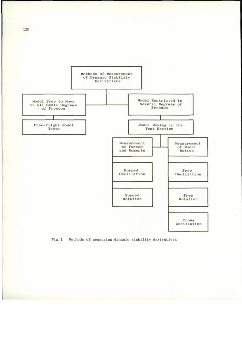
8/10/2019 Techniques for Measurement of Dynamic Stability Derivatives in Ground Test Facilities
http://slidepdf.com/reader/full/techniques-for-measurement-of-dynamic-stability-derivatives-in-ground-test 140/236
120
Methods of Measurement
of Dynamic Stability
Derivatives
Model Free to Move
in All Basic Degrees
of Freedom
Model Restricted in
Several Degrees of
Freedom
Free-Flight Model
Tests
Model Moving in the
Test Section
Measurement
of Forces
and Moments
Forced
Oscillation
Forced
Rotation
Measurement
of Model
Motion
Free
Oscillation
Free
Rotation
Cross
Oscillation
Pig.
1 Methods of measuring dynamic stability derivatives
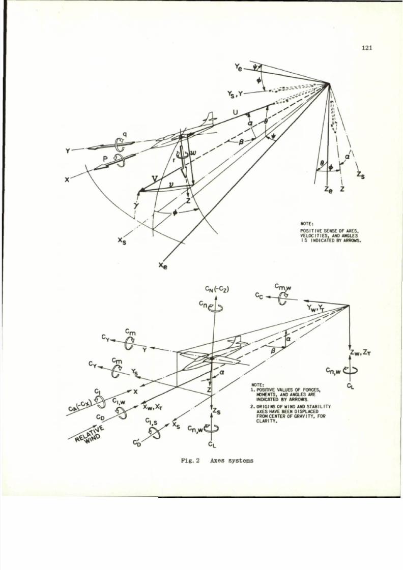
8/10/2019 Techniques for Measurement of Dynamic Stability Derivatives in Ground Test Facilities
http://slidepdf.com/reader/full/techniques-for-measurement-of-dynamic-stability-derivatives-in-ground-test 141/236
121
POSITIVE SENSE OF AXES,
VEL OC ITIES , AND ANGLES
I S INDICATE D BY ARROWS.
c
N
(-c
z
)
Z W . Z T
C n , w O
NOTE:
1 . POSITIVE VALUES OF FORCES,
MOMENTS, AND ANGLES ARE
INDICATED BY ARROWS.
2 .
ORIGINS OF WIND AND STABILITY
AXES HAVE BEEN DISPLACED
FROM CENTER OF G RAVI TY , FOR
C L A R I TY .
C
L
Pig . 2 Axes system s
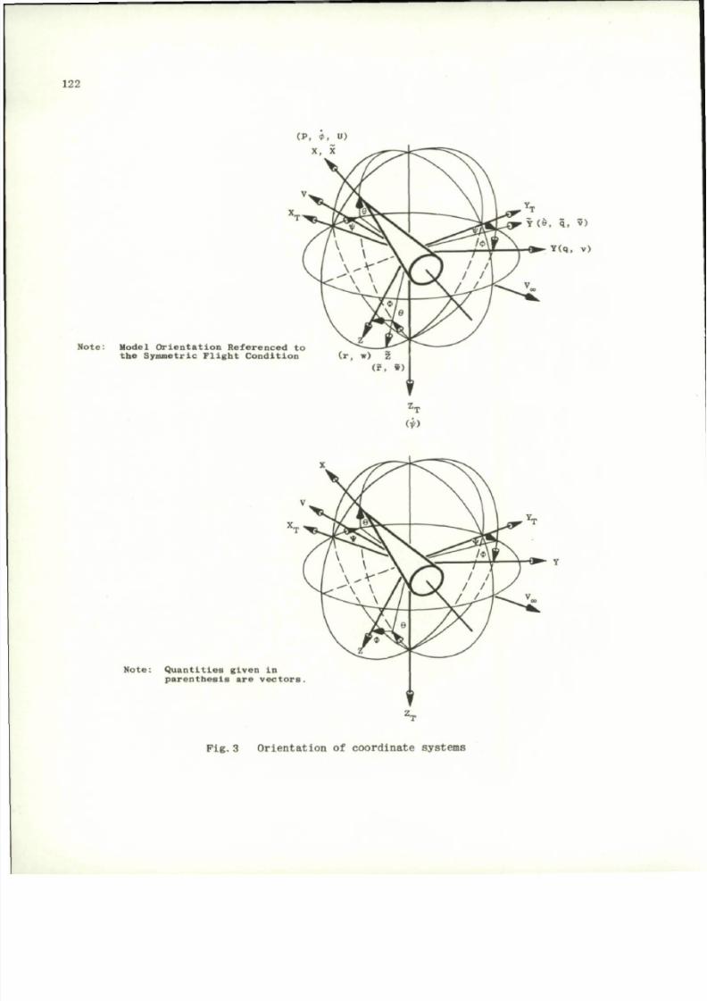
8/10/2019 Techniques for Measurement of Dynamic Stability Derivatives in Ground Test Facilities
http://slidepdf.com/reader/full/techniques-for-measurement-of-dynamic-stability-derivatives-in-ground-test 142/236
122
Note:
M o d e l O r i en t a t i on R e f e r en c e d t o
t h e S y m m e t r i c F l i g h t C on d i t i o n
N o t e:
Quantiti es given in
p a r en t h e s i s a r e v e c t o r s .
Pig. 3 Orientation of coordinate systems
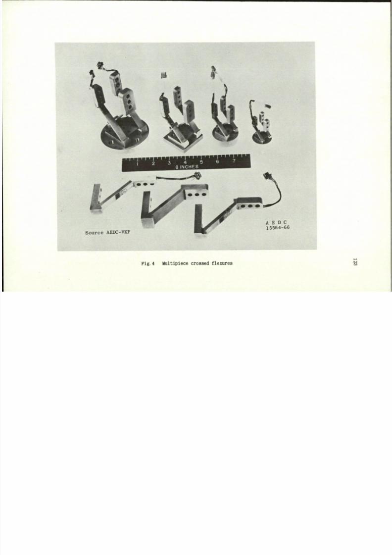
8/10/2019 Techniques for Measurement of Dynamic Stability Derivatives in Ground Test Facilities
http://slidepdf.com/reader/full/techniques-for-measurement-of-dynamic-stability-derivatives-in-ground-test 143/236
S o u r c e AEDC-VKF
A E D C
1 5 5 6 4 - 6 6
Pig.4 Multlpiece crossed flexures
'ci
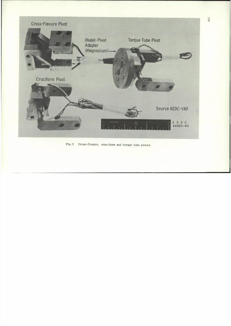
8/10/2019 Techniques for Measurement of Dynamic Stability Derivatives in Ground Test Facilities
http://slidepdf.com/reader/full/techniques-for-measurement-of-dynamic-stability-derivatives-in-ground-test 144/236
Cross-Flexure Pivot
Model-Pivot
Adapter
(Magnesium)
Torque Tube Pivot
Cruciform Pivot
Source AEDC-VKF
A E D C
44920-64
Pig.5 Cross-flexure, cruciform and torque tube pivots
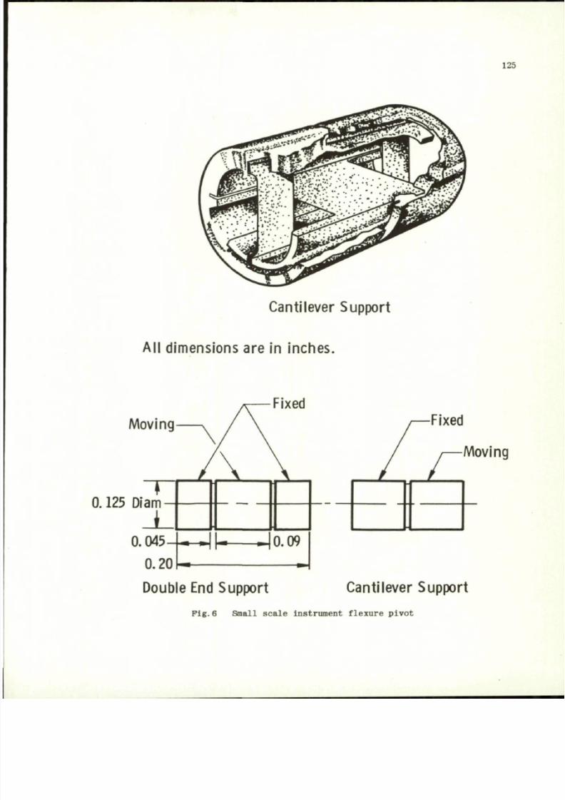
8/10/2019 Techniques for Measurement of Dynamic Stability Derivatives in Ground Test Facilities
http://slidepdf.com/reader/full/techniques-for-measurement-of-dynamic-stability-derivatives-in-ground-test 145/236
125
Canti lever Support
Al l dimensions are in inches.
Moving
0.125 Diam
J
0.045
0.20
Fixed
Moving
Double End Support
Canti lever Support
Fig. 6 Small scale instrument flexure pivot
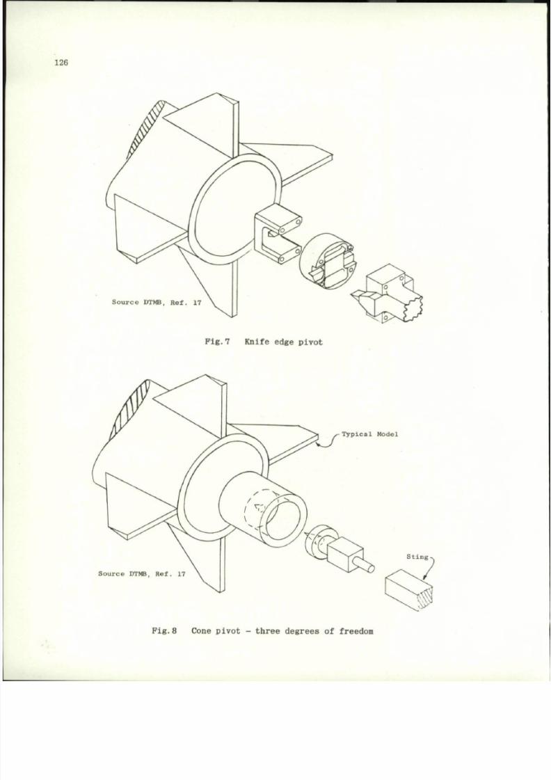
8/10/2019 Techniques for Measurement of Dynamic Stability Derivatives in Ground Test Facilities
http://slidepdf.com/reader/full/techniques-for-measurement-of-dynamic-stability-derivatives-in-ground-test 146/236
126
So ur ce DTMB, Ref . 17
Pig .7 Knife edge pivot
Source DTMB, Ref. 17
Typical Model
Sting.
Pig .8 Cone pivot - three degrees of freedom
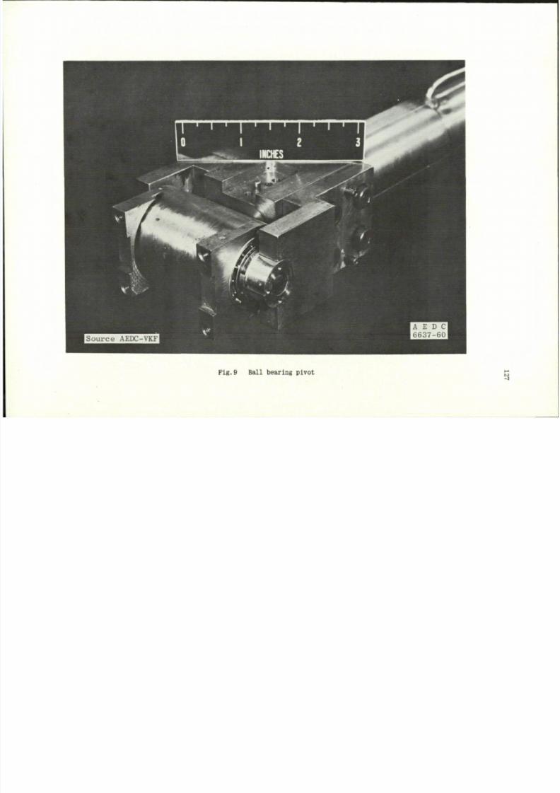
8/10/2019 Techniques for Measurement of Dynamic Stability Derivatives in Ground Test Facilities
http://slidepdf.com/reader/full/techniques-for-measurement-of-dynamic-stability-derivatives-in-ground-test 147/236
Fig . 9 Bal l bear in g p iv o t
3
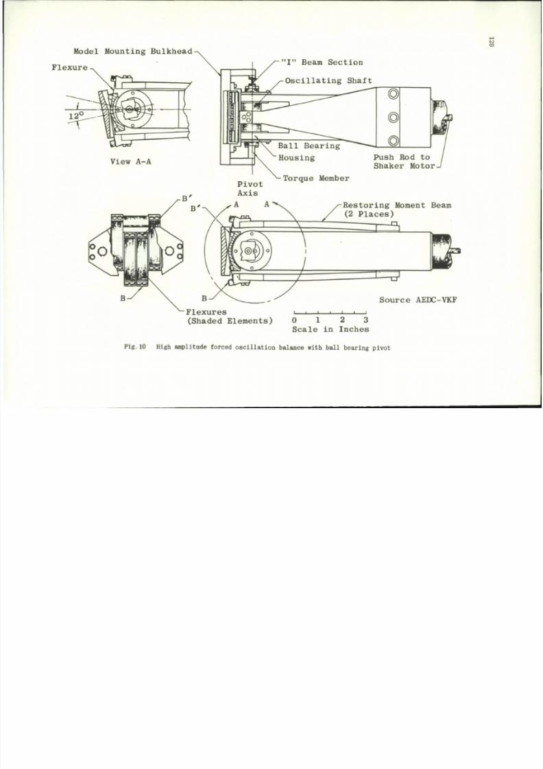
8/10/2019 Techniques for Measurement of Dynamic Stability Derivatives in Ground Test Facilities
http://slidepdf.com/reader/full/techniques-for-measurement-of-dynamic-stability-derivatives-in-ground-test 148/236
Model Mounting Bulkhead
Flexure
S
" I "
B e a m Se c t i on
O s c i l l a t i n g S h a f t
Source AEDC-VKF
(S ha de d E l em e n t s) 0 1 2 3
S c a l e i n I n c h e s
Pig.10 High amplitude forced osc il l at io n balance with bal l bearing pivot
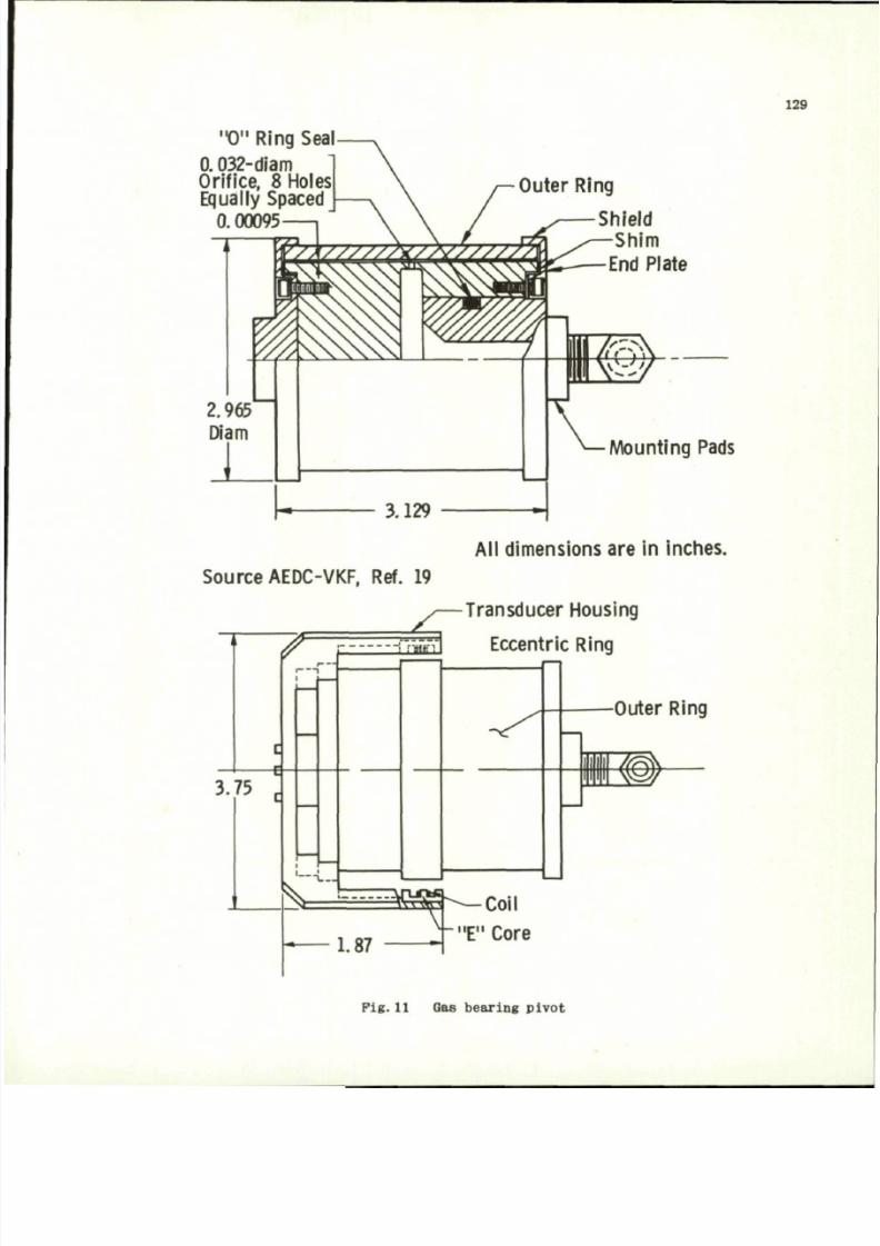
8/10/2019 Techniques for Measurement of Dynamic Stability Derivatives in Ground Test Facilities
http://slidepdf.com/reader/full/techniques-for-measurement-of-dynamic-stability-derivatives-in-ground-test 149/236
129
" 0 "
Ring Seal
0.032-diam
Orifice, 8 Holes
Equally Spaced
0.00095—
Outer Ring
Shield
Shim
End Plate
2.965
Diam
Mounting Pads
Source AEDC-VKF, Ref. 19
All dimensions are in inches.
Transducer Housing
T
3.75
k
U —
'• Q B E
Eccentric Ring
•Outer Ring
^ S ^ - C o i l
1.87
\ - n c i
E" Core
Pig .11 Gas bearing pivo t
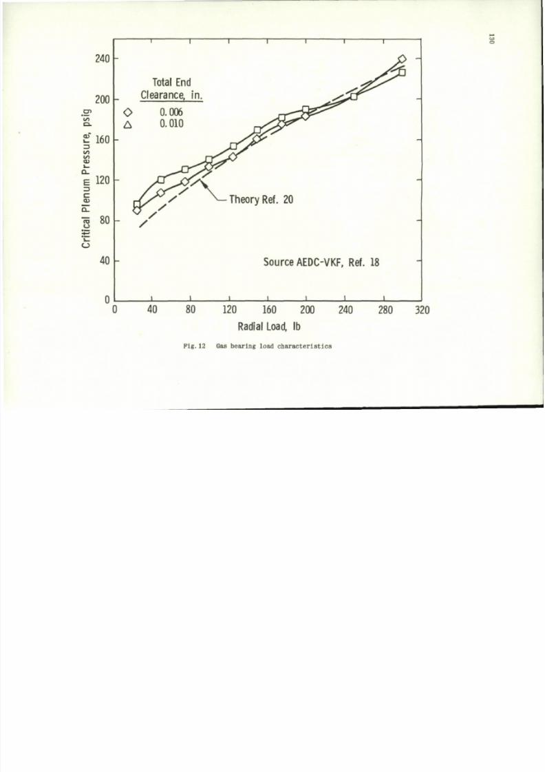
8/10/2019 Techniques for Measurement of Dynamic Stability Derivatives in Ground Test Facilities
http://slidepdf.com/reader/full/techniques-for-measurement-of-dynamic-stability-derivatives-in-ground-test 150/236
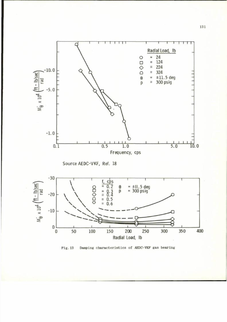
8/10/2019 Techniques for Measurement of Dynamic Stability Derivatives in Ground Test Facilities
http://slidepdf.com/reader/full/techniques-for-measurement-of-dynamic-stability-derivatives-in-ground-test 151/236
131
.-10.0
• a
i n
-5.0
X
. CD
•1 . 0
0.1
1— I I I I I
o
D
0
Q
e
p
Radial
Load,
lb
- 24
a 124
s 224
s 324
• ±11 .5 deg
~ 300 psig
0.5 1.0
Frequency, cps
J
i i I i i
5.0
10.0
Source
AEDC-VKF, Ref. 18
o
CD
T 3
ro
I
X
CD
150 200 250
Radial
Load, lb
Pig. 13 Damping charac teris tics
of
AEDC-VKP
g a s
bearing
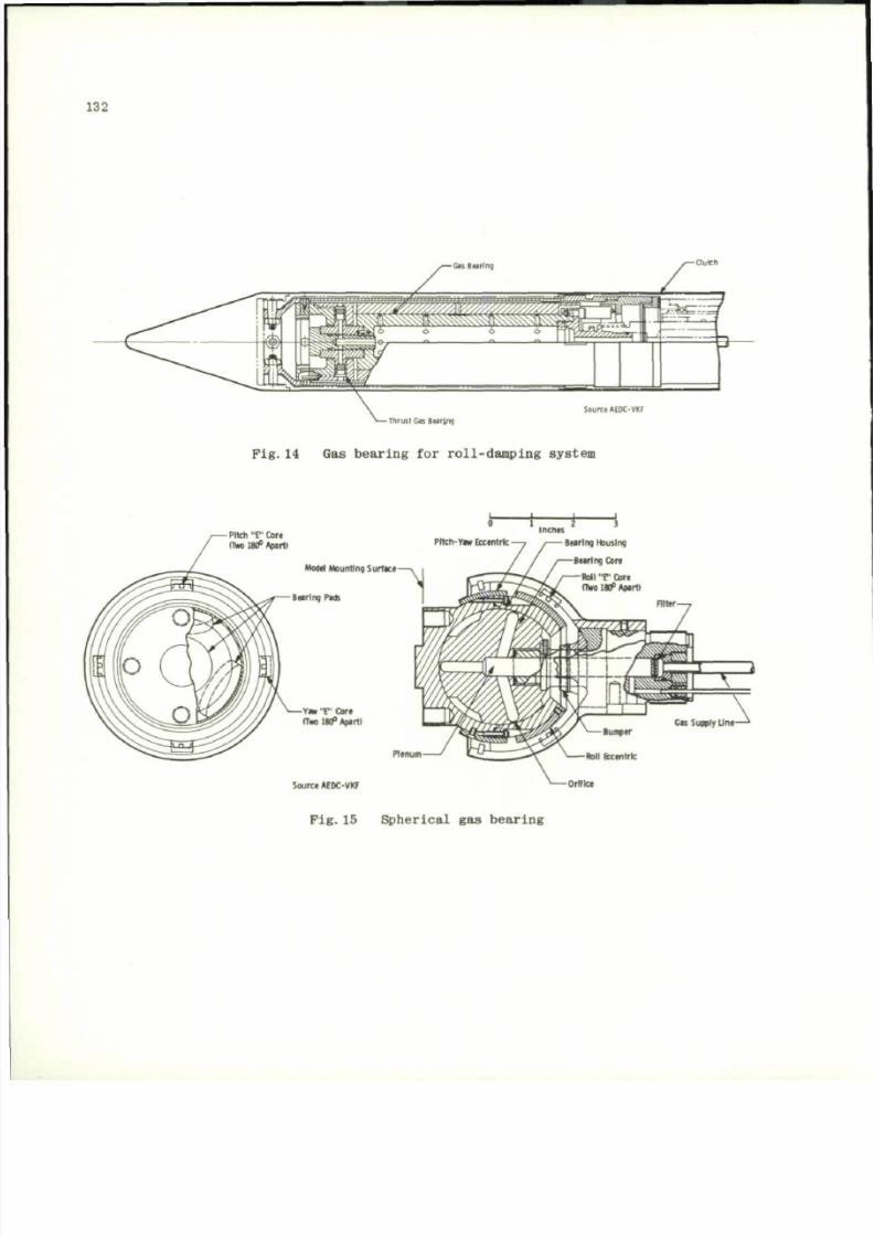
8/10/2019 Techniques for Measurement of Dynamic Stability Derivatives in Ground Test Facilities
http://slidepdf.com/reader/full/techniques-for-measurement-of-dynamic-stability-derivatives-in-ground-test 152/236
132
Source AEOC-VKF
-Th ru st Gas Bearing
Fig.14 G as bearing for roll-dampi ng system
_i-
PPtch
T '
Core
(Tw 180* Apart*
Pltch-Y»w Eccentric
Model Mounting Surface
Bearing Pads
Y w
" t "
Cora
(Tm 180° Apart)
Source AEDC-YKF
Plenum
-Bearing Housing
-Bearing Core
P i g . 1 5 S p h e r i ca l g a s b ea r i n g
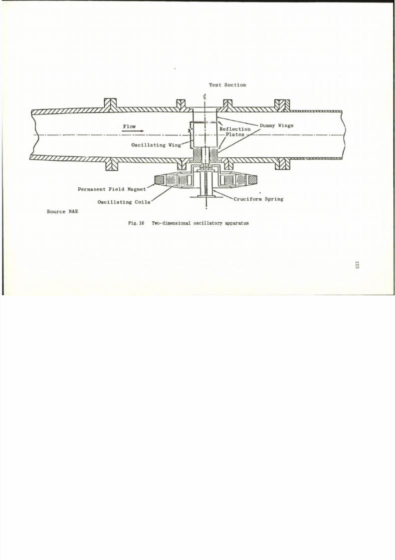
8/10/2019 Techniques for Measurement of Dynamic Stability Derivatives in Ground Test Facilities
http://slidepdf.com/reader/full/techniques-for-measurement-of-dynamic-stability-derivatives-in-ground-test 153/236
T e s t S e c t i o n
2
2
Z2gaZ^222£SSSSSSSSSSSSSfZ5
I p - X « K \ \ \ \ \ \ \ \ \ ^ f < H
Permanent Field Magnet
Oscillating Colls
Cruciform Spring
Source NAE
P i g . 1 6 T w o -d i me n si o na l o s c i l l a t o r y a p p a r a t u s
CO
'mm
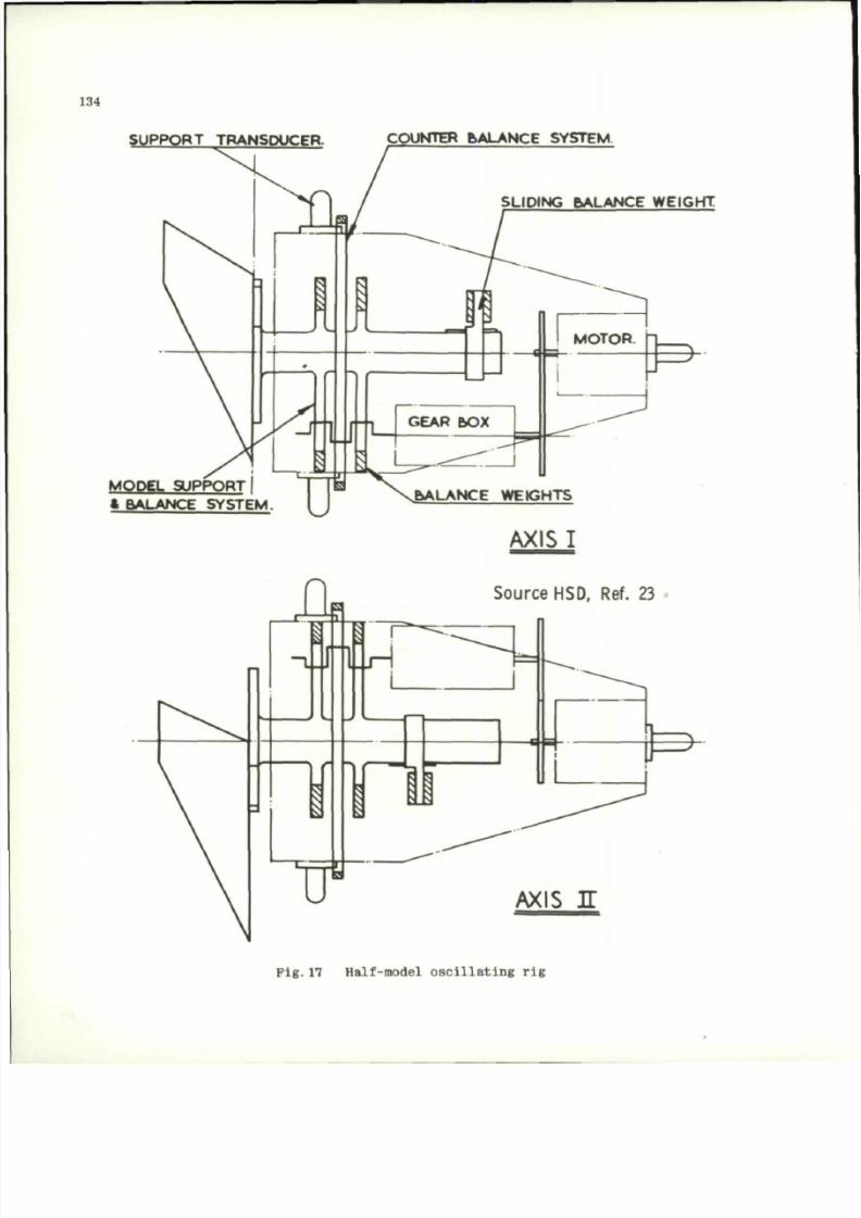
8/10/2019 Techniques for Measurement of Dynamic Stability Derivatives in Ground Test Facilities
http://slidepdf.com/reader/full/techniques-for-measurement-of-dynamic-stability-derivatives-in-ground-test 154/236
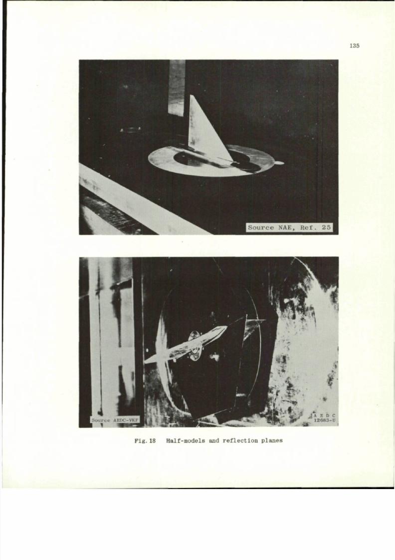
8/10/2019 Techniques for Measurement of Dynamic Stability Derivatives in Ground Test Facilities
http://slidepdf.com/reader/full/techniques-for-measurement-of-dynamic-stability-derivatives-in-ground-test 155/236
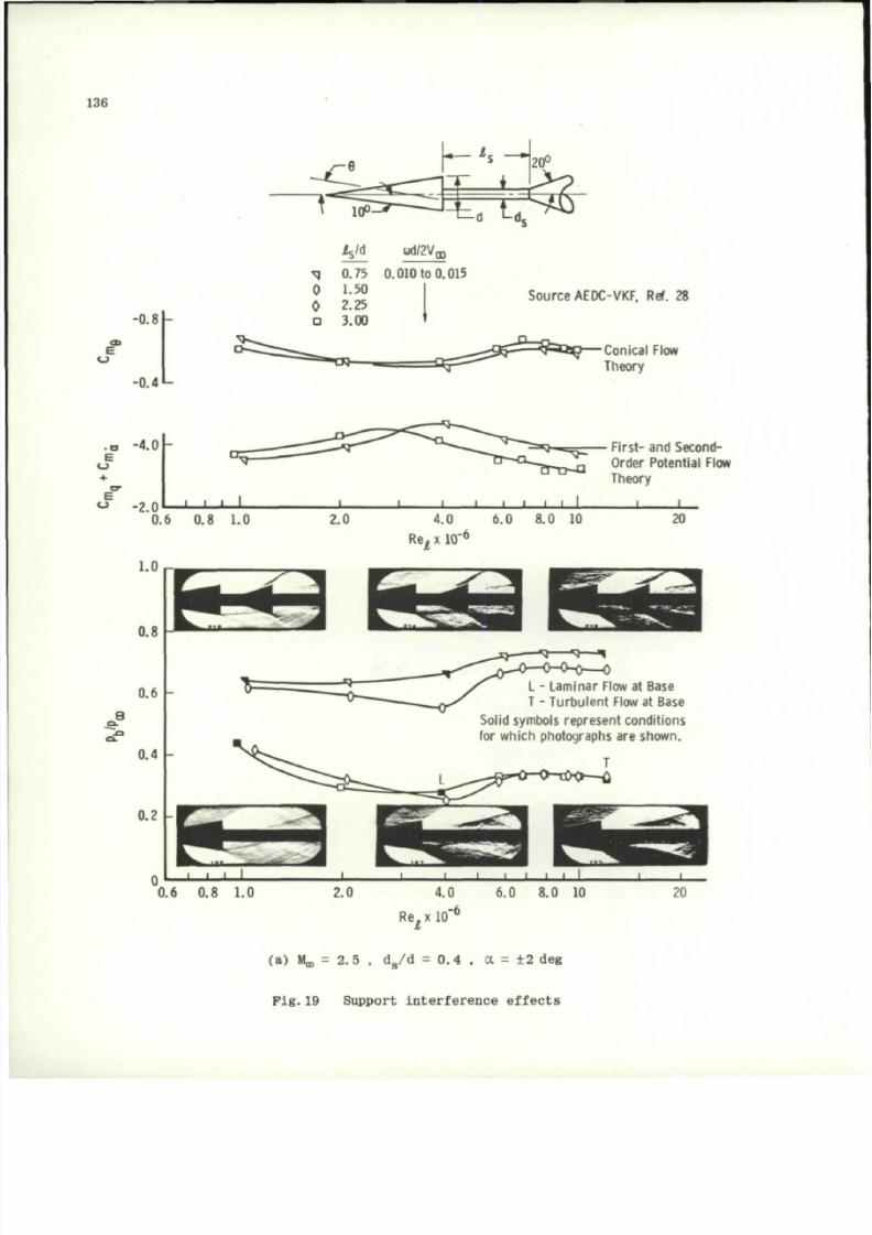
8/10/2019 Techniques for Measurement of Dynamic Stability Derivatives in Ground Test Facilities
http://slidepdf.com/reader/full/techniques-for-measurement-of-dynamic-stability-derivatives-in-ground-test 156/236
136
-0.8
-0.4
Vd
od/2V
00
^ 0.75 0.010 to 0.015
0 1.50
0 2.25
D
3.00
Source AEDC-VKF, Ref. 28
Conical Flow
Theory
- a
E
o
E
O
-4.0
-2.0
• • . I
0.6 0.8 1.0
8
1.0
0.8
0.6 -
0.4 -
0.2
2.0
_ L
Firs t- and Second-
Order Potential Flow
Theory
l I
4.0 6.0 8.0 10
20
Re
t
x 10"
6
-«q T —
m
L - Laminar Flow at Base
T - Tu rb u lent Flow at Base
Solid symbols represent conditions
for which photographs are shown.
0.6 0,8 1.0
Re.x 10
I
(a ) M^ =
2.
5 , d_/d = 0.4 , a = ± 2 deg
Fig.19 Support interference effects
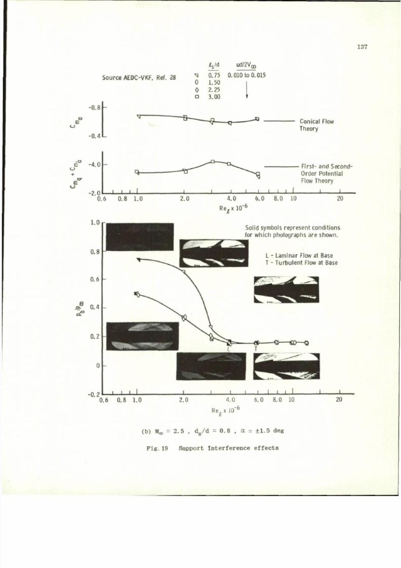
8/10/2019 Techniques for Measurement of Dynamic Stability Derivatives in Ground Test Facilities
http://slidepdf.com/reader/full/techniques-for-measurement-of-dynamic-stability-derivatives-in-ground-test 157/236
137
Source AEDC-VKF,
Ref. 28
-0.8
-
-0.4
V
d
ud/2V
03
XI
0
0
D
0.75
1.50
2.25
3.00
0.010 to 0.015
Conical Flow
Theory
e ° -4.0
E
o
-2.0
I I I I
0.6 0.8 1.0
0.6 0.8 1.0
Firs t- and Second-
Order Potential
Flow Theory
2.0
4.0 6.0 8.0 10
Re^xlO
6
20
Solid symbols represent conditions
for which photographs
are
s hown.
L
-
Laminar Flow
at
Base
T - Turbulent Flow at Base
Re.x
10
(b) M = 2.5 , d„/d =0.8 , a = ±1.5 deg
Fig.19 Support Interference effects

8/10/2019 Techniques for Measurement of Dynamic Stability Derivatives in Ground Test Facilities
http://slidepdf.com/reader/full/techniques-for-measurement-of-dynamic-stability-derivatives-in-ground-test 158/236
138
CD
E
-0.8
-0.4
i
s
/d ud^Vo)
^ 0.75 0.010 to 0.013
0 1.50
0 2.25
a 3.00
_a_
S ^ P
5
-
Source AEDC-VKF, Ref. 28
Conical Flow
Theory
.o -4.0 -
E
o
+
E "
U
-2.0
I I I I
0.6 0.8 1.0
8
•9 -
J I
J I 1_L
First- and Second-
Order Potential Flow
Theory
2.0 4.0 6.0 8.0 10
Re^ x
10 '
6
Solid symbols represent conditions
for which photographs are shown.
0.6 0.8 1.0
6.0 8.0 10
R e ,
x
1(
(a ) M^ = 3 . d
s
/ d = 0 . 4 , a = ± 2 d eg
F i g . 2 0 S u p po rt i n t e r f e r e n c e e f f e c t s
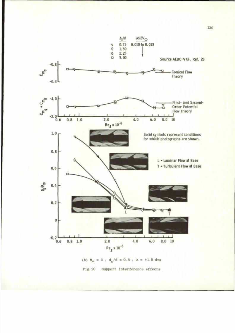
8/10/2019 Techniques for Measurement of Dynamic Stability Derivatives in Ground Test Facilities
http://slidepdf.com/reader/full/techniques-for-measurement-of-dynamic-stability-derivatives-in-ground-test 159/236
139
-0.8
-0.4
L i d ud/2V
co
^ 0.75 0.010 to 0.013
0 1.50
0 2.25
o 3.00
Source AEDC-VKF, Ref. 28
- & ~ ~ ^ = Z -
•
Conical Flow
Theory
fe
o -4.0
+
c
E
o
-2.0
I I I I
0.6 0.8 1.0
First- and Second-
Order Potential
Flow Theory
J L J i L -L
2.0
R e, x 10'
4,0 6.0 8.0 10
Solid symbols represent conditions
for which photographs are shown.
L -Laminar Flow at Base
T - Turbulent Flow at Base
0.6 0.8 1.0
6.0 8.0 10
Re.x 10
(b) M
ro
= 3 , d
s
/d = 0 .8 . CC = ±1.5 deg
P i g .2 0 S u p p o rt i n t e r f e r e n c e e f f e c t s
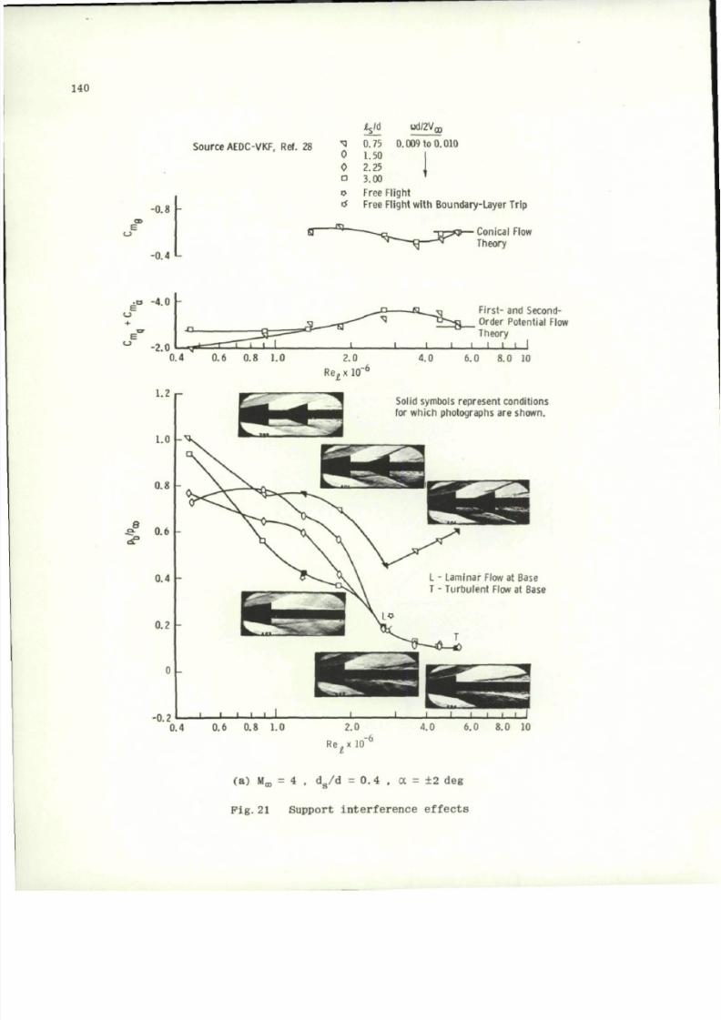
8/10/2019 Techniques for Measurement of Dynamic Stability Derivatives in Ground Test Facilities
http://slidepdf.com/reader/full/techniques-for-measurement-of-dynamic-stability-derivatives-in-ground-test 160/236
140
V
d
od/2V,
O
Source AEDC-VKF, Ref. 28
-0.8 -
-0.4 L
xi 0.75 0.009 to 0.010
0 1.50
0 2.25
o 3.00
o Free Flight
tf Free Flight with Boundary-Layer Trip
• Conical Flow
Theory
a ^ r j First- and Second-
'^"-•g Order Potential Flow
Theory
I I I I I I J. J
0.4 0.6 0.8 1.0
2.0
Re^
x 10
6
4.0 6.0 8.0 10
Solid symbols represent conditions
for which photographs are s hown.
L - Laminar Flow at Base
T - Turbulent Flow at Base
0.4 0.6 0.8 1.0
6.0 8.0 10
Re.x 10
(a ) M ^ = 4 , d
s
/d = 0.4 . a = ± 2 deg
Pig.21 Support interference effects
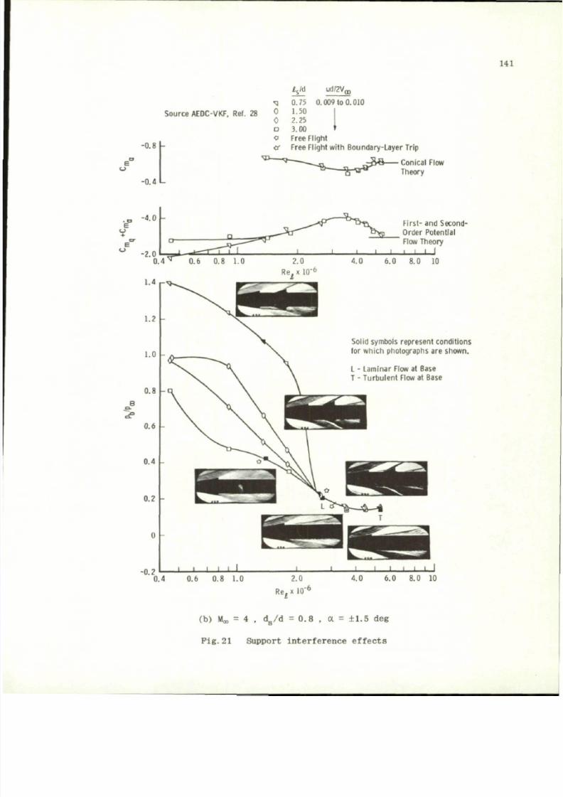
8/10/2019 Techniques for Measurement of Dynamic Stability Derivatives in Ground Test Facilities
http://slidepdf.com/reader/full/techniques-for-measurement-of-dynamic-stability-derivatives-in-ground-test 161/236
Source AEDC-VKF. Ref. 28
E
-0.8
-0.4 L
XI
0
0
a
0
£
s
/d UOVZVQJ
0.75 0.009 to 0.010
1.50
2.25
3.00
Free F light
or Free Flight with Boundary-Layer Trip
Conical Flow
Theory
141
e
-4.0 -
8
1-4 r
1.2
1.0
0.8
0.6
0.4
0.?
-0.2
0.4
First- and Second-
Order Potential
Flow Theory
| ' | i I
0.8 1.0 8.0 10
R e ^ x l O "
6
Solid symbols represent conditions
(or which photographs are shown.
L - Laminar Flow at Base
T - Tu rbu lent Flow at Base
1
0.6
i
i
0.8
1
1.0
1
2.0
Rej x 10 "
6
4.0
6.0 8.0 10
(b) Mo,
= 4 , d
g
/d = 0.8
,
a =
±1.5
deg
Pig.21 Support interference effect s
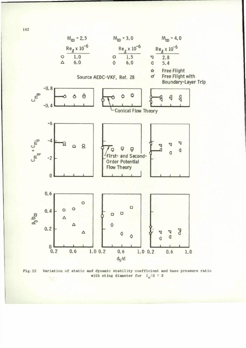
8/10/2019 Techniques for Measurement of Dynamic Stability Derivatives in Ground Test Facilities
http://slidepdf.com/reader/full/techniques-for-measurement-of-dynamic-stability-derivatives-in-ground-test 162/236
142
M
m
=
2.5
' C O
R e
i
x
-6
Moo-3.0
Re.
x 10"
o
A
1.0
6.0
D
0
1.5
6.0
Source AEDC-VKF, Ref. 28
Re^ x 10"
6
^J 2.8
0 5.4
& Free Flight
rf Free Flight with
Boundary-Layer Trip
Conical Flow Theory
E
7
•? 9
First- and Second-
Order Potential
Flow Theory
. . . i
8
a .
u . u
0.4
0.2
n
_ o
A
i
o
o
A
A
. 1 1
M * 3
j .
0.2 0.6 1.0 0.2 0.6 1.0 0.2 0.6 1.0
d
s
/d
Fig.22 Variation
of
static
and
dynamic stability coefficient
and
base pressure ratio
with sting diameter
for Z
g
/d = 3
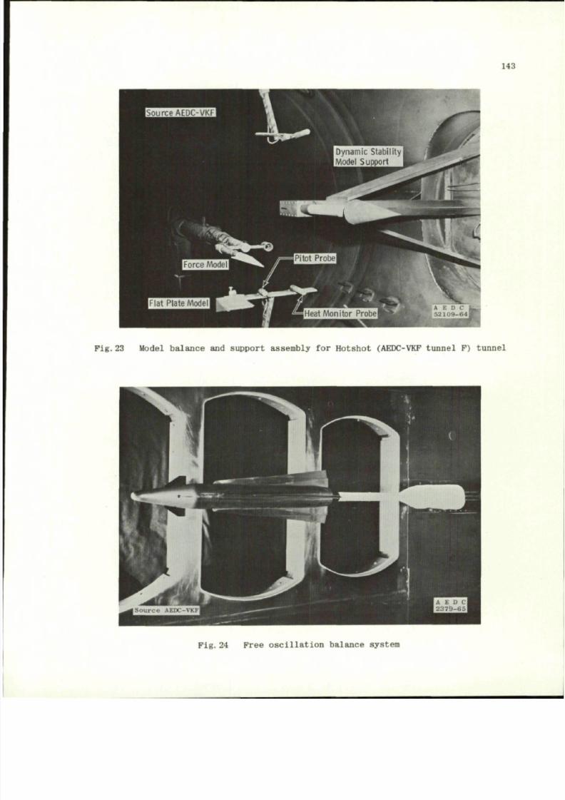
8/10/2019 Techniques for Measurement of Dynamic Stability Derivatives in Ground Test Facilities
http://slidepdf.com/reader/full/techniques-for-measurement-of-dynamic-stability-derivatives-in-ground-test 163/236
143
Pig.23 Model bala nce and support assembly for Hotsho t (AEDC-VKF tunnel P) tunnel
Fig. 24 Free oscil latio n balance system
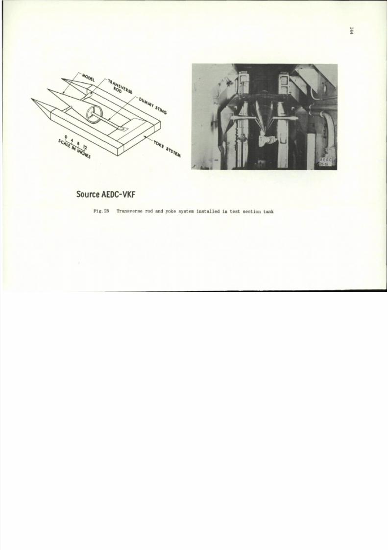
8/10/2019 Techniques for Measurement of Dynamic Stability Derivatives in Ground Test Facilities
http://slidepdf.com/reader/full/techniques-for-measurement-of-dynamic-stability-derivatives-in-ground-test 164/236
Source AEDC-VKF
Pig.25 Transverse rod and yoke system installed in test section tank
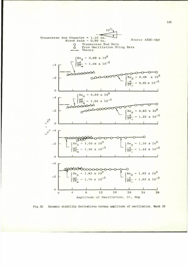
8/10/2019 Techniques for Measurement of Dynamic Stability Derivatives in Ground Test Facilities
http://slidepdf.com/reader/full/techniques-for-measurement-of-dynamic-stability-derivatives-in-ground-test 165/236
145
1 0
T r a n s v e r s e Rod D i a m e t e r - 1 .1 0 i n .
P i v o t A x i s - 0 . 6 0 i n .
O T r a n s v e r s e R od D a t a
A F r e e O s c i l l a t i o n S t i n g D a ta
— . _ T h e or y
Source AEDC-VKF
- 4 i -
- 2
0
- 1
- 2
• e
E
U 0
= 0 . 9 1 x 1 0
R e . - 0 . 6 9 x 1 0
cod _ T
-ryrj- « 1 . 0 4 X 1 0
- - ^ r * * * * * *
C T - 4
- 2
1.16 x 10
6
0
- 4
- 2 -
= 1.4 4 x 10
— i t t f r C
Re^ = 1 .8 3 x 1 0
6
% * - = 1 .7 0 x 1 0 "
3
1 1 1 1
R e
d
= 1 .8 3 x 1 0
6
'y^- = 1 .8 2 x 1 0 "
1 1 1
4 8 12 16 20 24 28
A m p l i t u d e o f O s c i l l a t i o n , ± 6 , d eg
F i g .2 6 D ynam ic s t a b i l i t y d e r i v a t i v e s v e r s u s a m p l i t u d e o f o s c i l l a t i o n , Mach 10
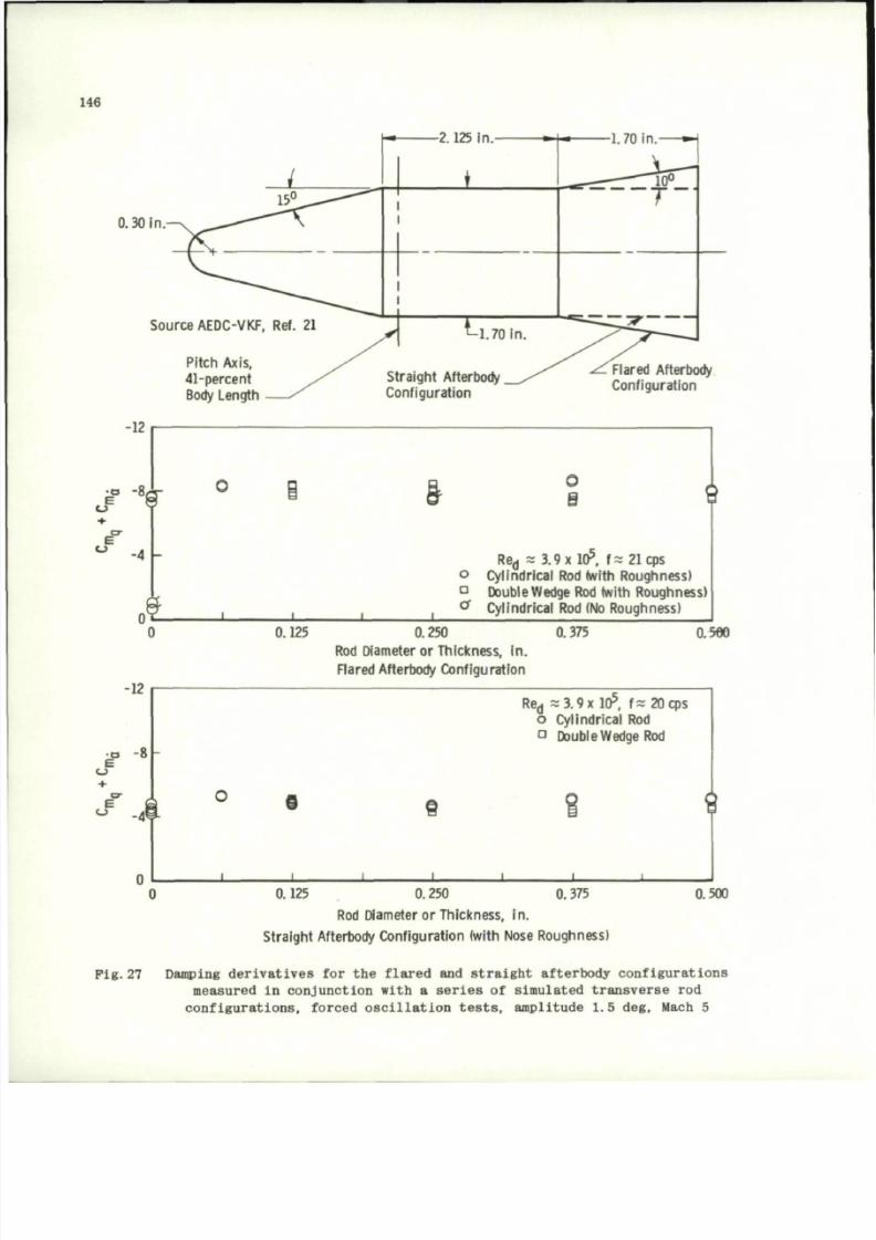
8/10/2019 Techniques for Measurement of Dynamic Stability Derivatives in Ground Test Facilities
http://slidepdf.com/reader/full/techniques-for-measurement-of-dynamic-stability-derivatives-in-ground-test 166/236
146
2.125 in.
0.30
in
Source AEDC-VKF.
Ref. 21
Pitch Axis,
41-percent
Body Length
-12
* -
8
8 -
+
o
E
-4
-
t
•12
•o
-8
e
Straight Afterbody
Conf igurat ion
Flared Afterbody
Conf igurat ion
&
0
8
9
o
D
a
Re
d
~ 3.9 x10
s
, f = 21 cps
Cy lindrica l Rod (with Roughnes s)
Double Wedge Rod (with Rou ghness)
Cylindrical Rod (No Roughness)
0.125 0.250
Rod Diameter
or
Thickness,
in.
Flared Afterbody Configu ration
0.375
0.560
Re
d
= 3 . 9 x 10
5
,
f~
20 cps
o Cylindrical
Rod
O Doub le Wedge Rod
I
- L
e
i
9
-L
0.125
0.375.250
Rod Diameter or Thickness, in.
Straight Afterbody Configuration (with Nose Roughness)
0.500
Pig.27 D a m p ing d e r i v a t i v e s
for the
flared
and
straight afterbody configurat ions
m e a s u r e d in conjunction with a s e r i e s of simulated transverse rod
configurations, forced oscilla tion
tests,
amplitude 1.5 de g , M a c h 5
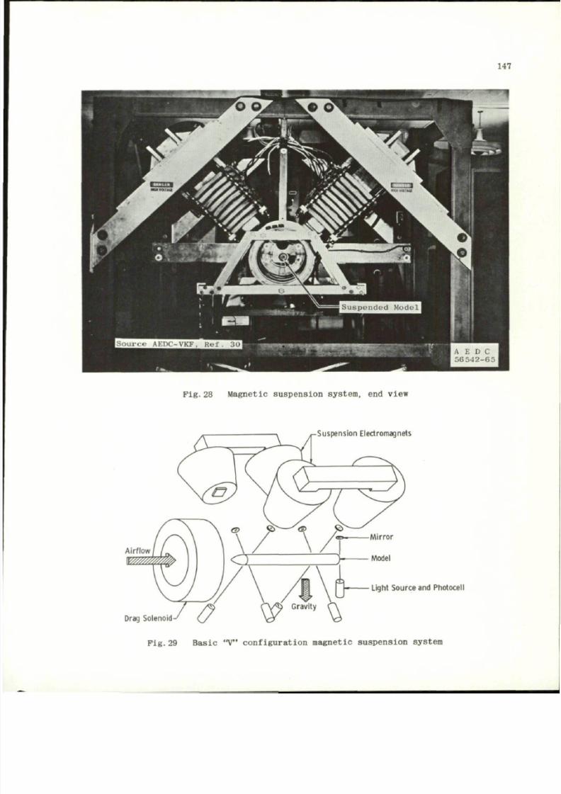
8/10/2019 Techniques for Measurement of Dynamic Stability Derivatives in Ground Test Facilities
http://slidepdf.com/reader/full/techniques-for-measurement-of-dynamic-stability-derivatives-in-ground-test 167/236
147
Pig.28 Magnetic suspension system,
end
view
Suspension Electromagnets
y Model
Light Sou rce and Photocell
Drag Solenoid
Pig.29 Basic
"V"
configuration m agnetic suspension system
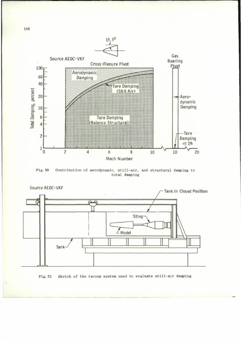
8/10/2019 Techniques for Measurement of Dynamic Stability Derivatives in Ground Test Facilities
http://slidepdf.com/reader/full/techniques-for-measurement-of-dynamic-stability-derivatives-in-ground-test 168/236
148
Source AEDC-VKF
15.5°
43
100
60
40
c
g 20
J 10
a 6
S 4
Cross -Flexure Pivot
Tare Damping
IKBalance Structural)
_ i _
6 8
Mach Number
10
Gas
Bearing
Piyot
V
^ A e r o
dynamic
Damping
Tare
Damping
« 1 %
10
20
F i g . 30 C o n t r i b u t i o n o f a e r o dy n ami c , s t i l l - a i r , and s t r u c t u r a l d amp in g t o
to ta l damping
Source AEDC-VKF
Tank in Closed Position
Pig.
31 Sket ch
of the
vacuum system used
to
evaluate still-air damping
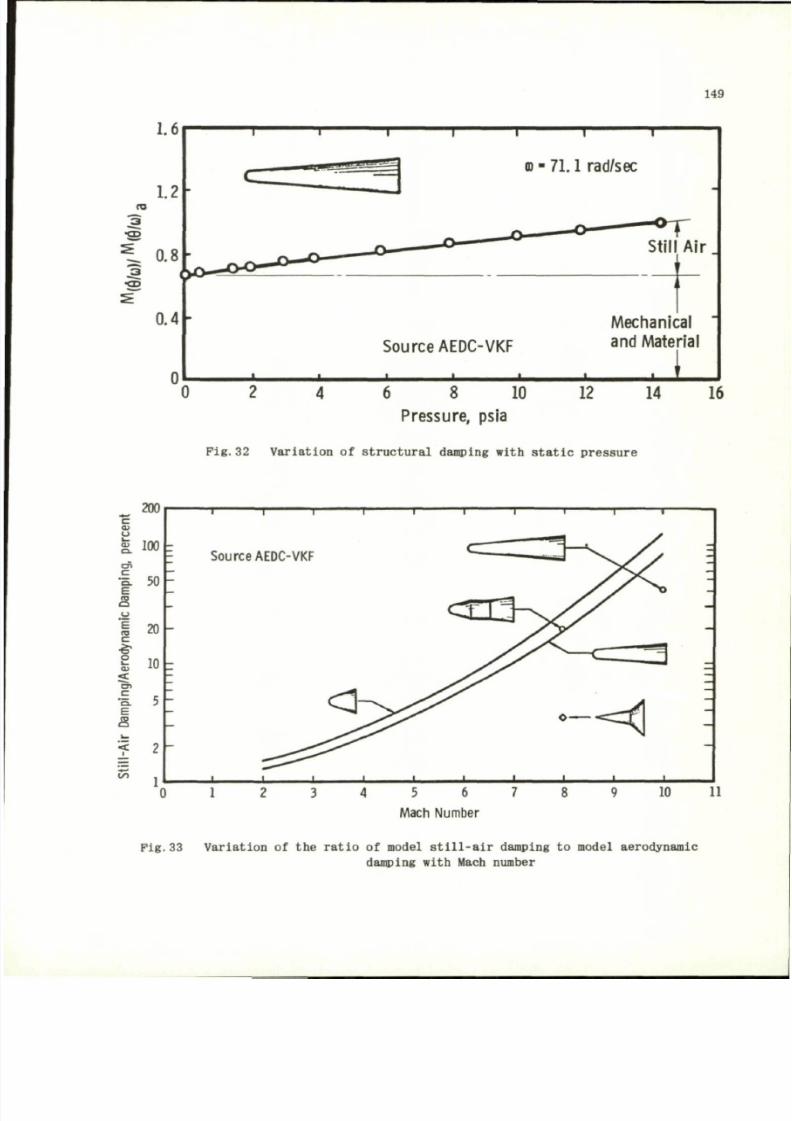
8/10/2019 Techniques for Measurement of Dynamic Stability Derivatives in Ground Test Facilities
http://slidepdf.com/reader/full/techniques-for-measurement-of-dynamic-stability-derivatives-in-ground-test 169/236
149
1.6
0.4
© - 71.1
rad/sec
Source AEDC-VKF
6
8 10
Pressure,
psia
Mechanical
and Material
. 1
12
14 16
Fig. 32 Variat ion
o f
structural damping with static pressure
200
*-.
c
i .
loo
• a
so
E
s
i 20
e
fe 10
<
-I 5h
E
s
Zn
1
I I
Source AEDC-VKF
0 1
5 6 7
Mach Number
8 9 10 11
F ig .33 Va r ia t i on o f the r a t i o o f model s t i l l - a i r damping to mode l ae rodynamic
damping with Mach number
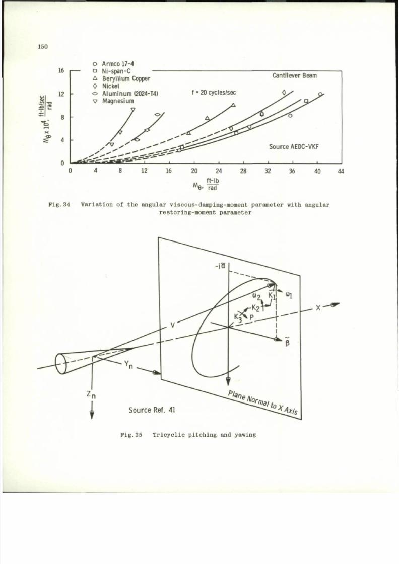
8/10/2019 Techniques for Measurement of Dynamic Stability Derivatives in Ground Test Facilities
http://slidepdf.com/reader/full/techniques-for-measurement-of-dynamic-stability-derivatives-in-ground-test 170/236
150
u
16
12 -
8 -
4 -
o Armco 17-4
D Ni-span-C —
A Bery llium Copper
0 Nickel
o Aluminum (2024-T4)
v Magnesium
A 7
*4%J04f2m ^ m T m m r t & ^ ' f ' ' L
8 12 16 20 24 28 32 36 40 44
M
ft-lb
9- rad
Pig .34 Va r ia t io n of the ang ular v i scous -damping-moment param eter w i th ang ular
r e s t o r i n g - mo men t p a r ame t e r
P i g . 3 5 T r i c y c l i c p i t ch i n g and y awi ng
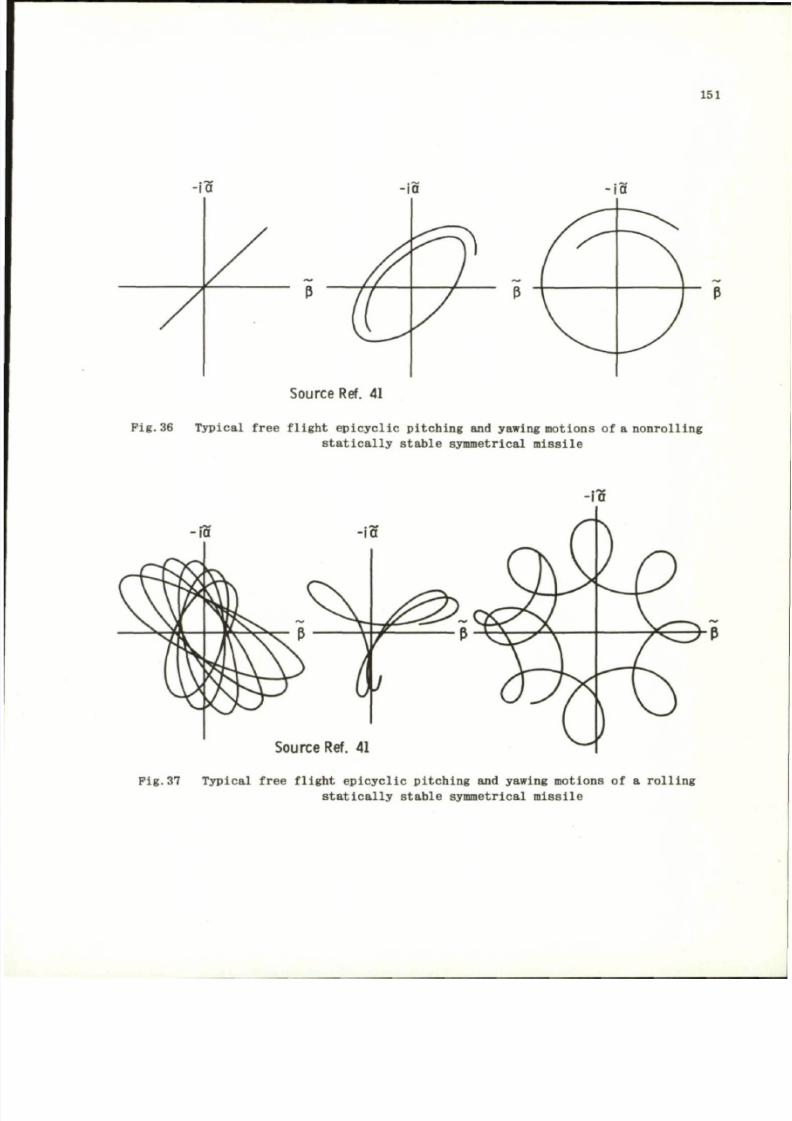
8/10/2019 Techniques for Measurement of Dynamic Stability Derivatives in Ground Test Facilities
http://slidepdf.com/reader/full/techniques-for-measurement-of-dynamic-stability-derivatives-in-ground-test 171/236
151
S o u r c e R e f . 41
P i g . 36 Typica l free flight epic yclic pitc hing and yawing moti ons of a nonrolling
statically stable symmetrical missile
S o u r c e
R e f . 41
Pig.37 Typic al free flight epicyclic pitching and yawing moti ons of a rolling
statically stable symmetrical missile
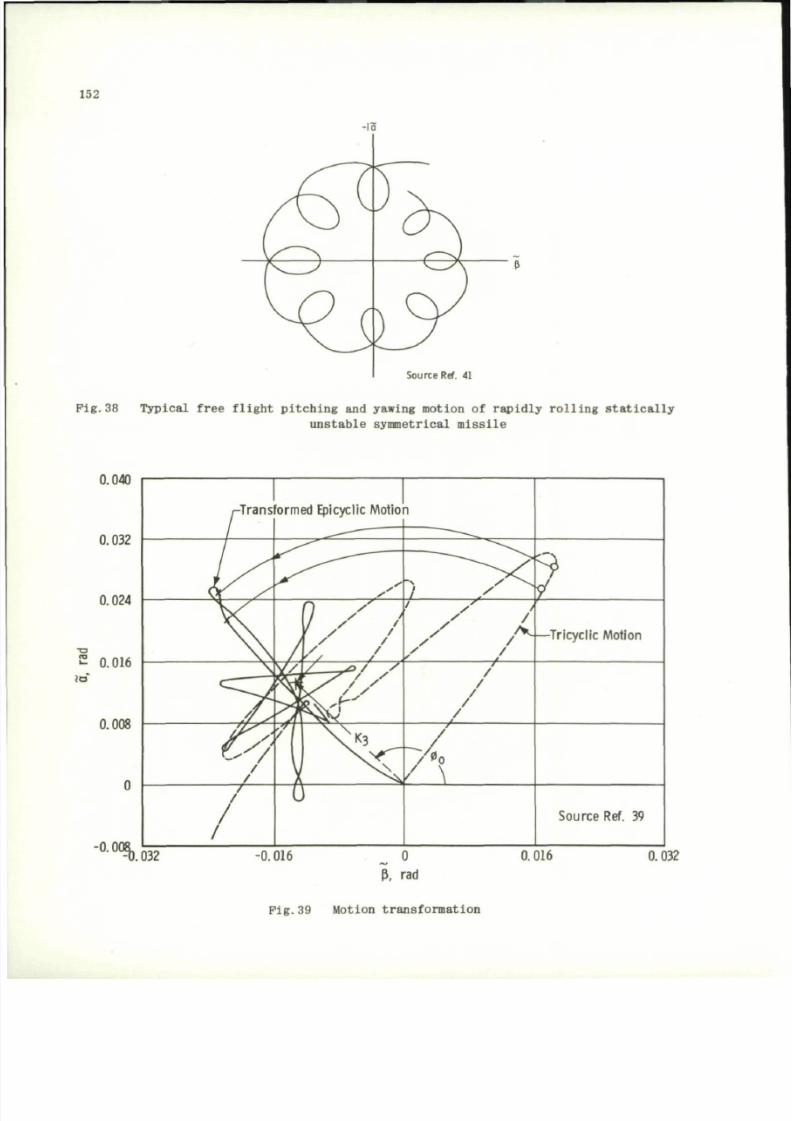
8/10/2019 Techniques for Measurement of Dynamic Stability Derivatives in Ground Test Facilities
http://slidepdf.com/reader/full/techniques-for-measurement-of-dynamic-stability-derivatives-in-ground-test 172/236
152
Source Ref. 41
P i g . 3 8 T y p i c a l f r e e f l i g h t p i t c h i n g a nd y aw in g m o ti on o f r a p i d l y r o l l i n g s t a t i c a l l y
u n s t ab l e s y mmet r i ca l m i s s i l e
0.040
2 0.016
0.032
F i g . 3 9 M o tio n t r an s f o r m a t i o n
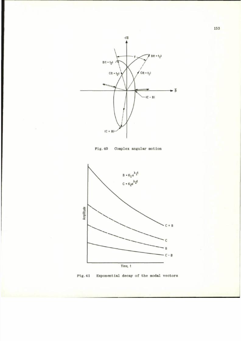
8/10/2019 Techniques for Measurement of Dynamic Stability Derivatives in Ground Test Facilities
http://slidepdf.com/reader/full/techniques-for-measurement-of-dynamic-stability-derivatives-in-ground-test 173/236
153
-1
B(t-t
2
»
/
T \
\
\ /
cft • t
2
> y
******mmj \
( C +
B
i f l
3
— - y - ^ ^ ^ — T '
Btt -t i»
y f
\ / C ( t - t j )
i
/
* = »
^ - ( C - B)
Fig .40 Complex ang ular motion
B - K , e
X
l
X
?
t
C - K 2 6
l
C+ B
Time, t
F ig .41 Expon en t ia l decay o f th e modal ve c to rs
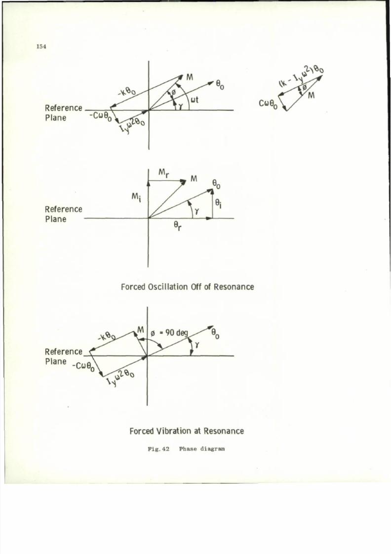
8/10/2019 Techniques for Measurement of Dynamic Stability Derivatives in Ground Test Facilities
http://slidepdf.com/reader/full/techniques-for-measurement-of-dynamic-stability-derivatives-in-ground-test 174/236
154
Reference
Plane
pfo
Reference
Plane
i
M:
1
M
r
r
• "7
/
/ > "
^
e
r
M
3
^
\
v .
B
i
Forced Oscillation Off of Resonance
Reference
Plane -Cuft
Forced Vibration at Resonance
Fi g .4 2 Phase d iagram
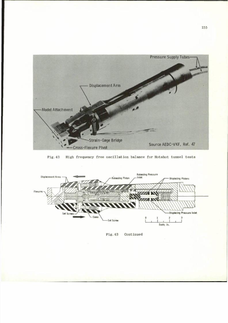
8/10/2019 Techniques for Measurement of Dynamic Stability Derivatives in Ground Test Facilities
http://slidepdf.com/reader/full/techniques-for-measurement-of-dynamic-stability-derivatives-in-ground-test 175/236
155
Pressure Supply Tubes-
-Strain-Gage Bridge
-•—Cross-Flexure Pivot
S o u r c e
A E D C - V K F , R ef . 47
P i g .
43 High frequency free oscil lati on balance
for
Hotshot tunnel test s
Displacement Arms
Flexures
Releasing Pressure
Inlet
Displacing Pistons
Displacing Pressure Inlet
1 2 3
-Set Screw
_ i _
Scale, in.
Pig.43 Continued
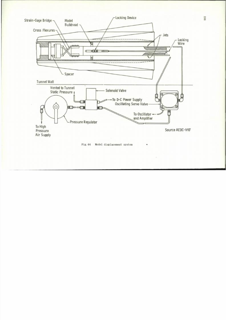
8/10/2019 Techniques for Measurement of Dynamic Stability Derivatives in Ground Test Facilities
http://slidepdf.com/reader/full/techniques-for-measurement-of-dynamic-stability-derivatives-in-ground-test 176/236
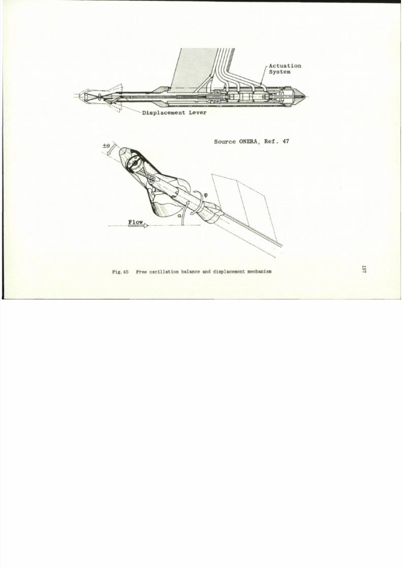
8/10/2019 Techniques for Measurement of Dynamic Stability Derivatives in Ground Test Facilities
http://slidepdf.com/reader/full/techniques-for-measurement-of-dynamic-stability-derivatives-in-ground-test 177/236
A c t u a t i o n
S y s t e m
D i s p l a c e m e n t L e v e r
S o u r c e O NE RA , R e f . 4 7
Fig. 45 Free o sc il la ti o n balance and displacement mechanism
3
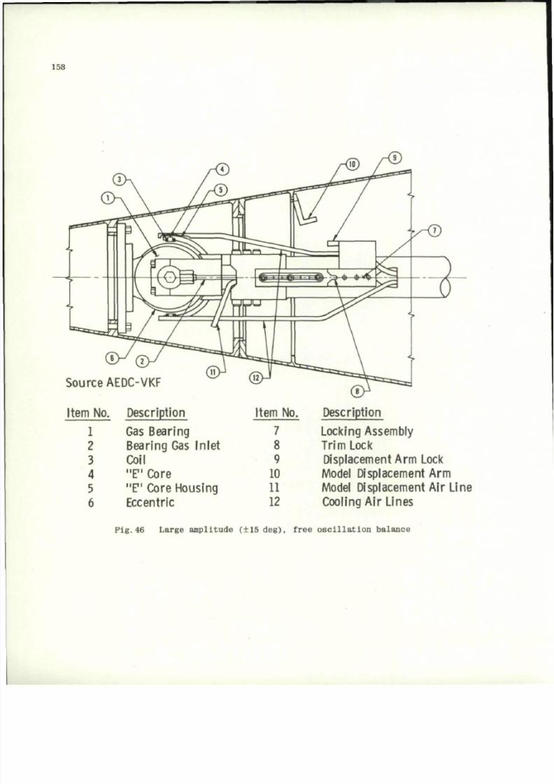
8/10/2019 Techniques for Measurement of Dynamic Stability Derivatives in Ground Test Facilities
http://slidepdf.com/reader/full/techniques-for-measurement-of-dynamic-stability-derivatives-in-ground-test 178/236
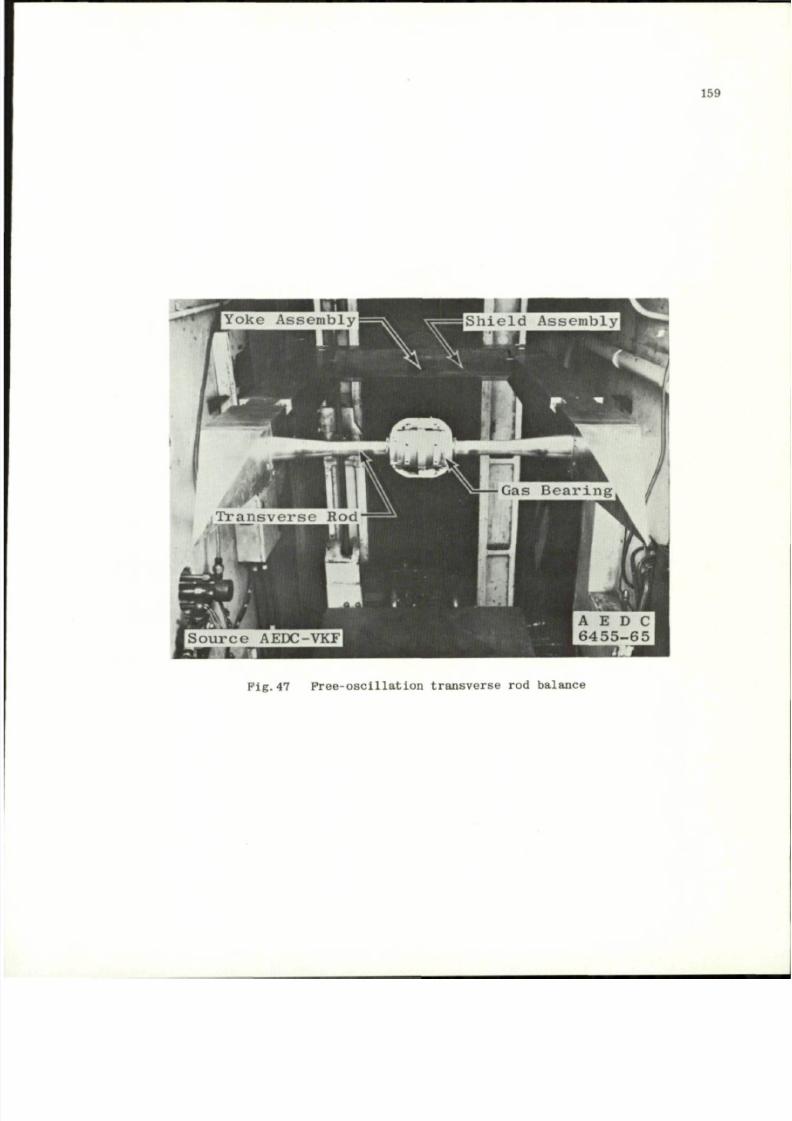
8/10/2019 Techniques for Measurement of Dynamic Stability Derivatives in Ground Test Facilities
http://slidepdf.com/reader/full/techniques-for-measurement-of-dynamic-stability-derivatives-in-ground-test 179/236
159
P i g . 4 7 F r e e - o s c i l l a t i o n t r a n s v e r s e r o d b a l an c e
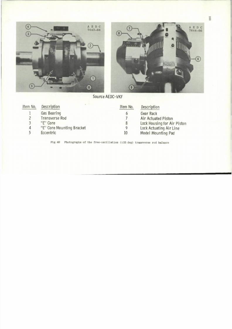
8/10/2019 Techniques for Measurement of Dynamic Stability Derivatives in Ground Test Facilities
http://slidepdf.com/reader/full/techniques-for-measurement-of-dynamic-stability-derivatives-in-ground-test 180/236
o
A E D C
7 6 4 3 - 6 6
A E D C
7 6 4 4 - 6 6
Sou rce AEDC-VKF
Item No.
1
2
3
4
5
Description
Gas Bearing
Transverse Rod
"E "
Core
"E " Core Mo u nting Bracket
Eccentric
Item No.
6
7
8
9
10
Description
Gear Rack
Air Actuated Piston
Lock Housing for Air Piston
Lock Actuating Air Line
Model Mounting Pad
Pig.48 Photographs
of the
free-oscil lation (+35 deg) t ransverse
rod
balance
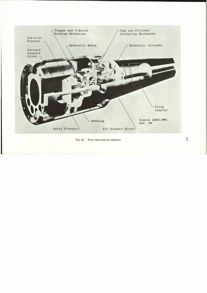
8/10/2019 Techniques for Measurement of Dynamic Stability Derivatives in Ground Test Facilities
http://slidepdf.com/reader/full/techniques-for-measurement-of-dynamic-stability-derivatives-in-ground-test 181/236
Vertical
Flexure
Forward
Support
Block
Tongue and V-Block
\Braking Mechanism
Hydraulic Motor
'/
Cam and Follower
Actuating Mechanism
Hydraulic Cylinder
%M*4
^•v*" 4« ^kfe
A x i a l F l e x u r e - ^
^ —H o u s in g \
A f t S u p p o r t B lo c k - ^
^ S t i n g
A d a p t e r
Source AEDC-PWT,
Ref . 49
Fig.49 Free-o scillatio n balance
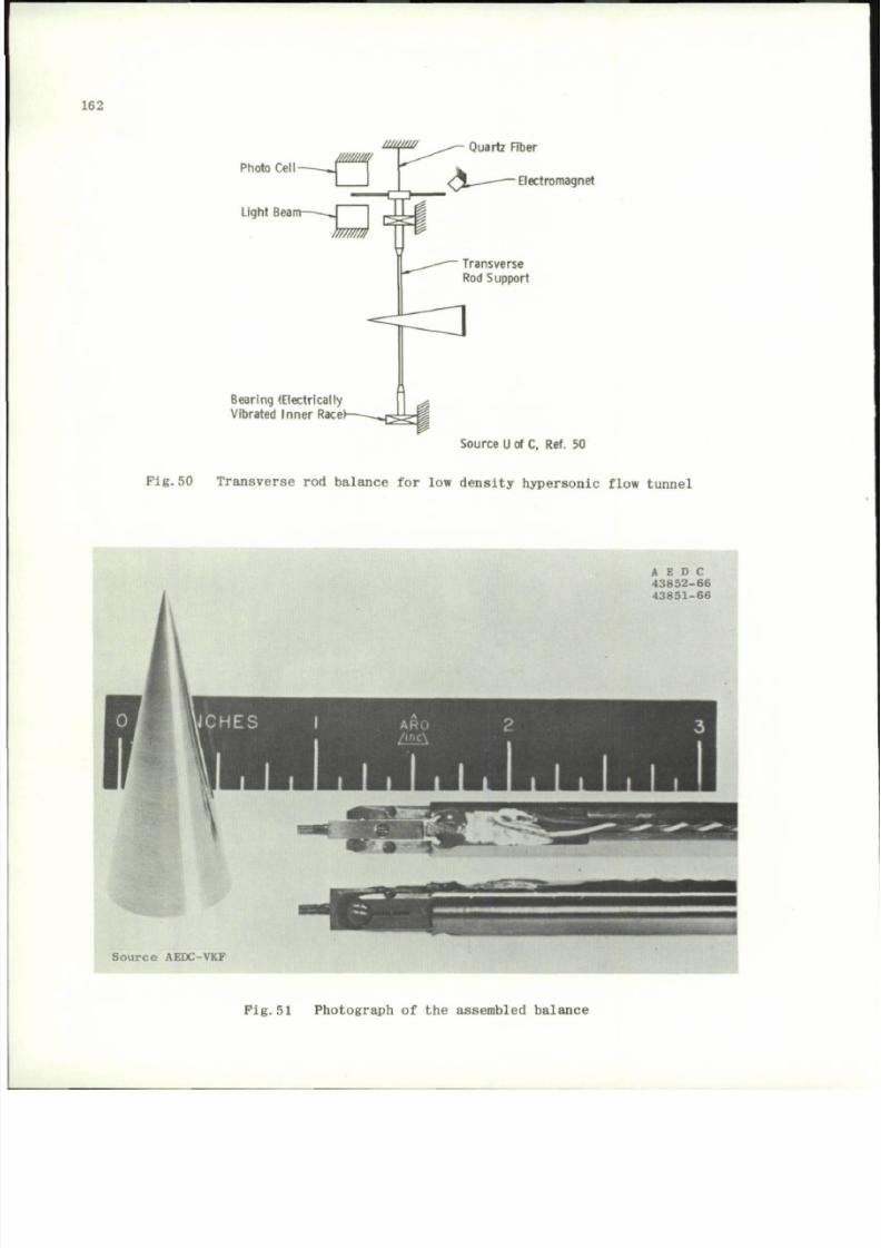
8/10/2019 Techniques for Measurement of Dynamic Stability Derivatives in Ground Test Facilities
http://slidepdf.com/reader/full/techniques-for-measurement-of-dynamic-stability-derivatives-in-ground-test 182/236
162
Photo Cell
m m /
Light Beam
Quartz Fiber
Electromagnet
Transverse
Rod Su pport
Bearing (Electrically
Vibrated Inner Race
Source U
of C,
Ref.
50
Fig. 50 Tra nsverse rod balance for low density hyper sonic flow tunnel
A E D C
4 3 8 5 2 - 6 6
4 3 8 5 1 - 6 6
S ource A E D C -V K F
Fig.51 Photograph
o f t h e
assembled balance
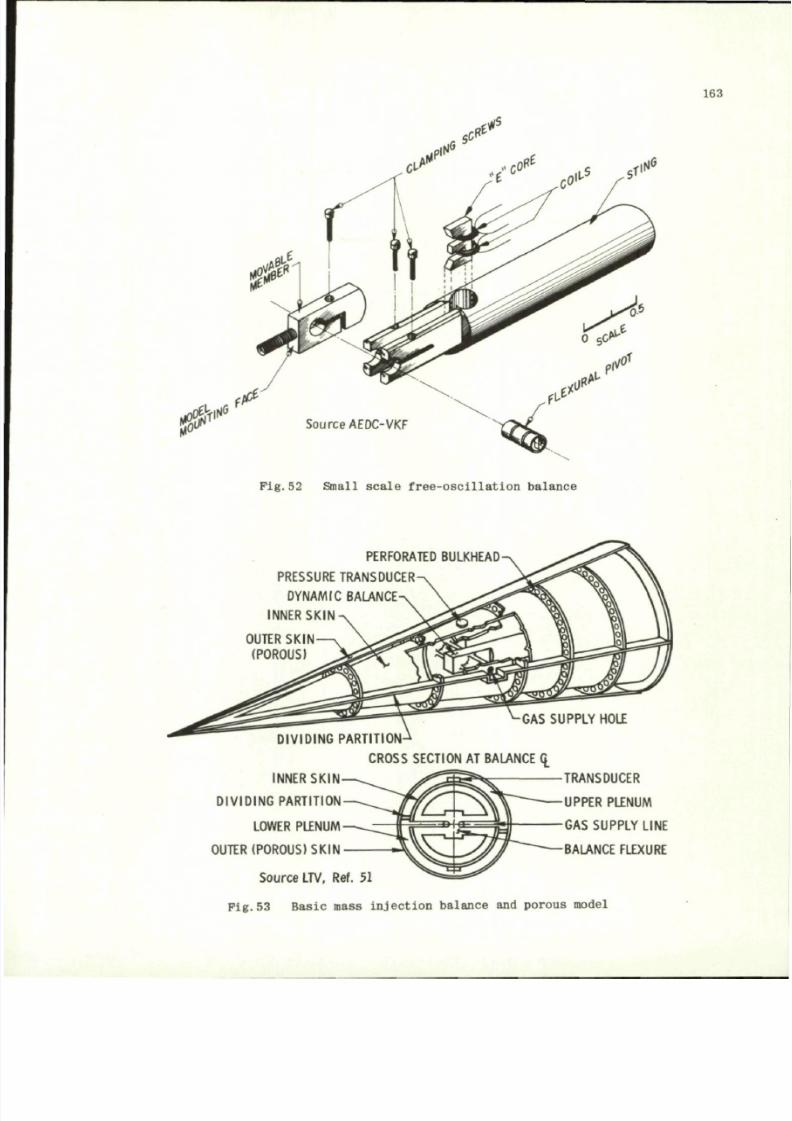
8/10/2019 Techniques for Measurement of Dynamic Stability Derivatives in Ground Test Facilities
http://slidepdf.com/reader/full/techniques-for-measurement-of-dynamic-stability-derivatives-in-ground-test 183/236
163
j jSF
1
Source AEDC-VKF
Pig. 52 Small scale free-oscillati on balance
PERFORATED BULKHEAD-
PRESSURE TRANSDUCER-
DYNAMIC BALANCE-
INNER SKIN
OUTER SKIN
(POROUS)
INNER SKIN
DIVIDING PARTITION
LOWER PLENUM
OUTER (POROUS) SKIN
GAS SUPPLY HOLE
RTITI ON-
CROSS SECTION
AT
BALANCE ^
TRANSDUCER
UPPER PLENUM
GAS SUPPLY LINE
BALANCE FLEXURE
S o u r c e
LTV, Ref. 51
Fig.53 Basic mass in jection balance and porous model
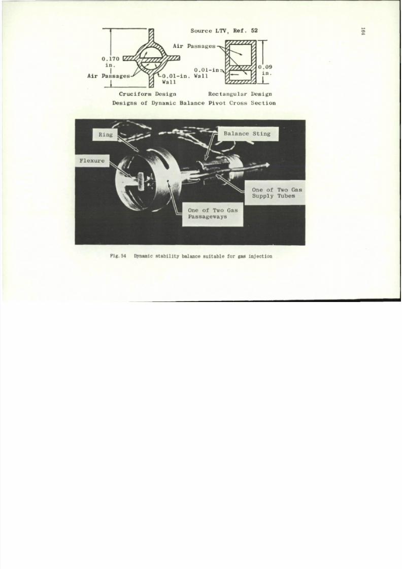
8/10/2019 Techniques for Measurement of Dynamic Stability Derivatives in Ground Test Facilities
http://slidepdf.com/reader/full/techniques-for-measurement-of-dynamic-stability-derivatives-in-ground-test 184/236
S o u r c e L T V, R e f . 5 2
VZZZZm7Z7
A
Air Passages
Air Passages
J
0.01-in. Wall
Wall
0.0i-in^?2^0
:
09
izzzzz^J.
Crucifo rm Design Rectangular Design
Designs of Dynamic Balance Pivot Cross Section
£
Pig.54 Dynamic stability balance suitable
f o r g a s
injection
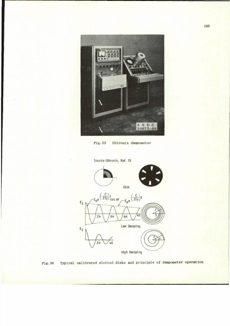
8/10/2019 Techniques for Measurement of Dynamic Stability Derivatives in Ground Test Facilities
http://slidepdf.com/reader/full/techniques-for-measurement-of-dynamic-stability-derivatives-in-ground-test 185/236
165
Pig. 55 Oltronix dampometer
Source Oltronix, Ref. 53
High Damping
Pig.56 Typic al calibrated slotted disks and principle o f dampometer operati on
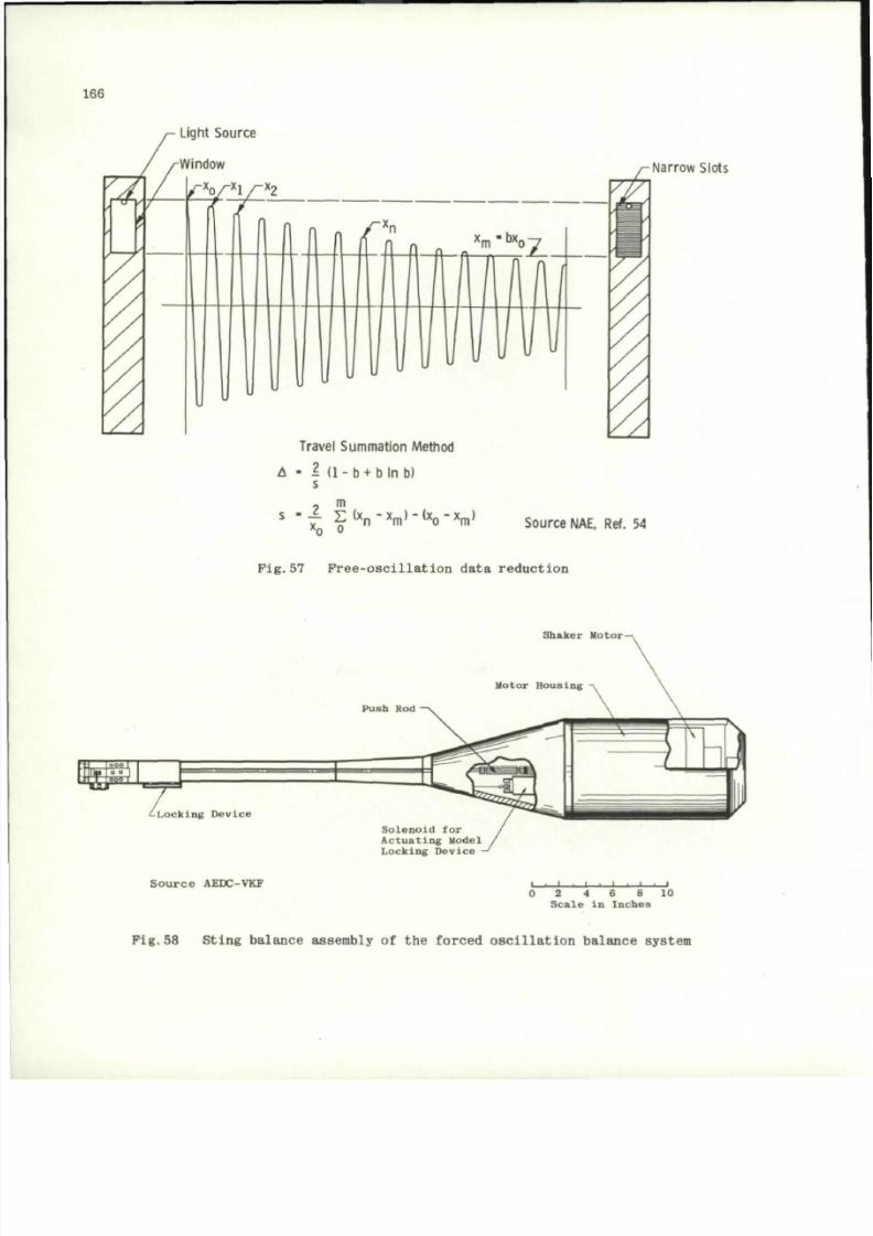
8/10/2019 Techniques for Measurement of Dynamic Stability Derivatives in Ground Test Facilities
http://slidepdf.com/reader/full/techniques-for-measurement-of-dynamic-stability-derivatives-in-ground-test 186/236
166
Light Source
Travel Summation Method
A
• I
( 1 - b + b l n b )
s
?
m
s - f E ( x
n
- x
m
) - ( x
0
- x
m
)
x
o
o
Narrow Slots
Source NAE, Ref.
54
Pig.57 Pree-oscil lation data reduction
S h a k e r M o t o r -
m
o I
' - L o c k i n g D e v i c e
P u s h Rod
S o l e n o i d
f or
A c t u a t i n g M o d e l
L o c k i n g D e v i c e
S ource A E D C -V K F i
i I i I i l i i i i
0 2 4 6 8 10
S c a l e
In
I n c h e s
Pig. 58 Sting balance assembl y
of
the forced oscillation balance system
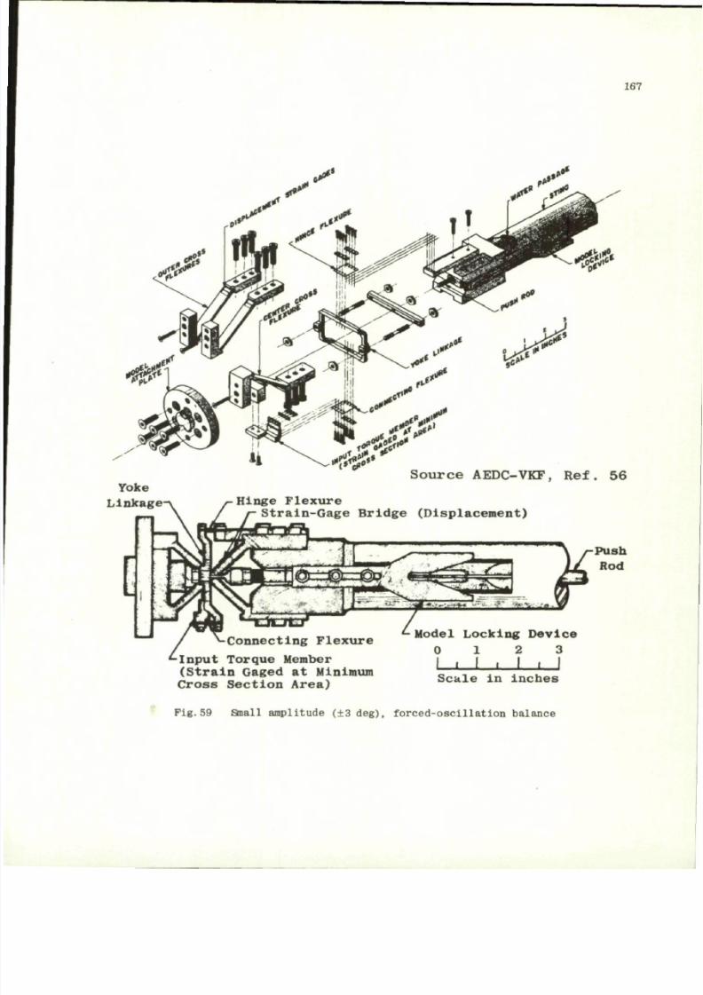
8/10/2019 Techniques for Measurement of Dynamic Stability Derivatives in Ground Test Facilities
http://slidepdf.com/reader/full/techniques-for-measurement-of-dynamic-stability-derivatives-in-ground-test 187/236
167
4$
Y o k e
L i n k a g e
S o u r c e A ED C -V K F, R e f . 5 6
[
Hinge Flexure
Strain-Gage Bridge (Displacement)
•Connecting Flexure
•Input Tor que Memb er
(Strain Gaged at Minimum
Cross Section Area)
Model Locking Device
0 1 2 3
• I I • I I I
S c a l e i n I n c h e s
Pig.59 Small amplitude (±3 deg), fo rce d- osc il la t io n balance
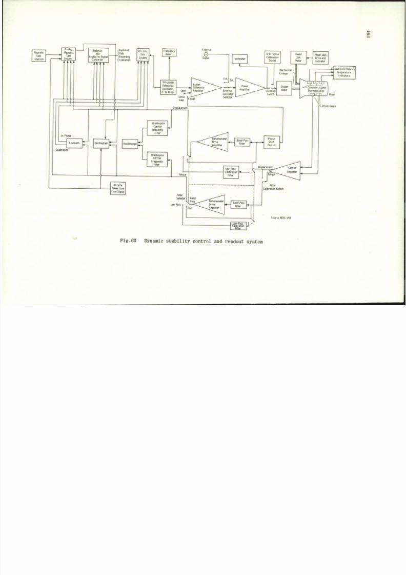
8/10/2019 Techniques for Measurement of Dynamic Stability Derivatives in Ground Test Facilities
http://slidepdf.com/reader/full/techniques-for-measurement-of-dynamic-stability-derivatives-in-ground-test 188/236
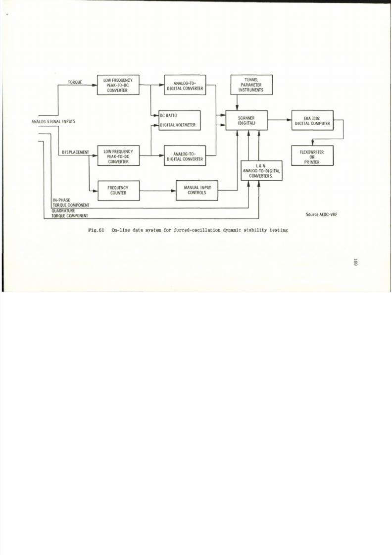
8/10/2019 Techniques for Measurement of Dynamic Stability Derivatives in Ground Test Facilities
http://slidepdf.com/reader/full/techniques-for-measurement-of-dynamic-stability-derivatives-in-ground-test 189/236
TORQUE
ANALOG SIGNAL INPUTS
DISPLACEMENT
IN-PHASE
TORQUE COMPONENT
LOW FREQUENCY
PEAK-TO-DC
CONVERTER
LOW FREQUENCY
PEAK-TO-DC
CONVERTER
FREQUENCY
COUNTER
ANALOG-TO-
DIGITAL CONVERTER
QUADRATURE
TORQUE COMPONENT
DC RATIO
DIGITAL VOLTMETER
ANALOG-TO-
DIGITAL CONVERTER
MANUAL INPUT
CONTROLS
TUNNEL
PARAMETER
INSTRUMENTS
I
SCANNER
(DIGITAL)
L & N
ANALOG-TO-DIGITAL
CONVERTERS
ERA 1102
DIGITAL COMPUTER
FLEXOWRITER
OR
PRINTER
Source AEOC-VKF
Pig.61 On- l ine data sys tem for force d-os ci l la t ion dynamic s ta bi l i ty tes t ing
a
to
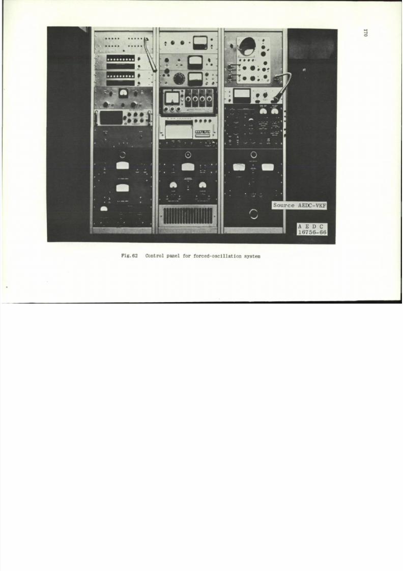
8/10/2019 Techniques for Measurement of Dynamic Stability Derivatives in Ground Test Facilities
http://slidepdf.com/reader/full/techniques-for-measurement-of-dynamic-stability-derivatives-in-ground-test 190/236
o
P i g . 6 2 C o n t r o l p a n e l f o r f o r c e d - o s c i l l a t i o n sy s te m
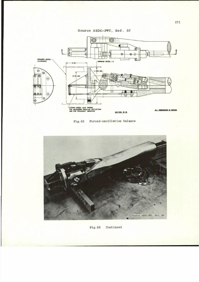
8/10/2019 Techniques for Measurement of Dynamic Stability Derivatives in Ground Test Facilities
http://slidepdf.com/reader/full/techniques-for-measurement-of-dynamic-stability-derivatives-in-ground-test 191/236
171
S o u r c e A ED C -P W T, R e f . 5 7
^STMM-GMD) LEV sptme
FO* UUSUWG ANOJUUt DcrLECTirx
w FOB m e o u o c r v u u n o N
StCTiow A-|>
F i g . 6 3 F o r c e d - o s c i l l a t i o n b a l a n ce
Pig.63 Continued
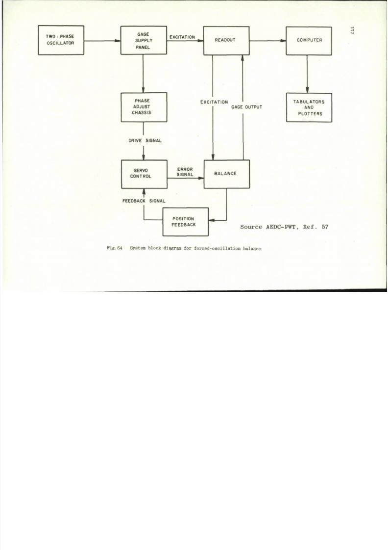
8/10/2019 Techniques for Measurement of Dynamic Stability Derivatives in Ground Test Facilities
http://slidepdf.com/reader/full/techniques-for-measurement-of-dynamic-stability-derivatives-in-ground-test 192/236
TWO - PHASE
OSCILLATOR
GAGE
SUPPLY
PANEL
EXCITATION
PHASE
ADJUST
CHASSIS
DRIVE SIGNAL
i
SERVO
CONTROL
T
FEEDBACK SIGNAL
READOUT
EXCITATION
GAGE OUTPUT
ERROR
SIGNAL
BALANCE
POSITION
FEEDBACK
COMPUTER
TABULATORS
AND
PLOTTERS
Source
AEDC-PWT, Ref. 57
to
Fig.64 System block diagram for forc ed-osc il lation balanc e
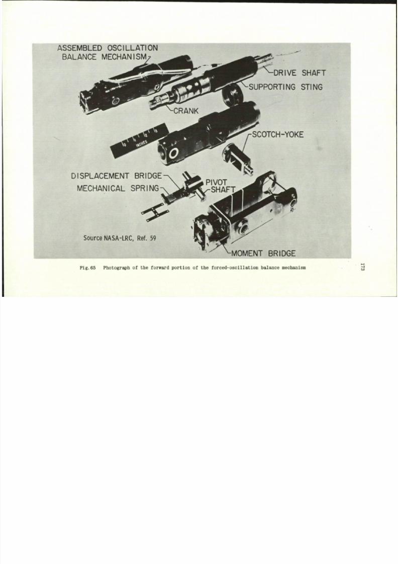
8/10/2019 Techniques for Measurement of Dynamic Stability Derivatives in Ground Test Facilities
http://slidepdf.com/reader/full/techniques-for-measurement-of-dynamic-stability-derivatives-in-ground-test 193/236
ASSEMBLED OSCILLATION
BALANCE MECHANISM
DRIVE SHAFT
OPTING STING
DISPLACEMENT BRIDGE
MECHANICAL SPRING
Source NASA-LRC. Ref. 59
SCOTCH-YOKE
PIVOT
SHAFT
MOMENT BRIDGE
Pig.65 Photograph of
the
forward po rtion of
the
forced-oscilla tion bala nce mechanism
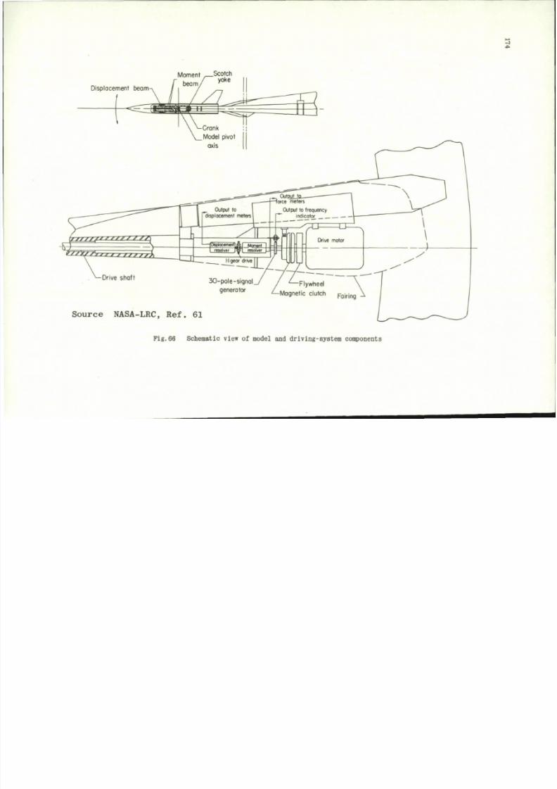
8/10/2019 Techniques for Measurement of Dynamic Stability Derivatives in Ground Test Facilities
http://slidepdf.com/reader/full/techniques-for-measurement-of-dynamic-stability-derivatives-in-ground-test 194/236
Moment ,—Scotch
yoke
Displacement beam
r
S o u rc e NASA-LRC, Re f . 61
Pig.66 Schemat ic view
o f
model
and
driving-syst em components
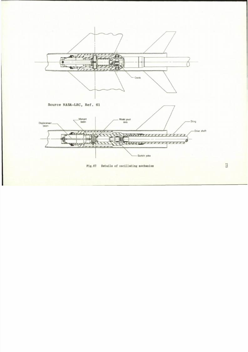
8/10/2019 Techniques for Measurement of Dynamic Stability Derivatives in Ground Test Facilities
http://slidepdf.com/reader/full/techniques-for-measurement-of-dynamic-stability-derivatives-in-ground-test 195/236
S o u r c e N A S A -L R C , R e f . 6 1
Displacement.
beam
_ Moment
beam
^ ^
Model pivot
axis
. \
j .
y y > / / / / / /
} / ' / ' * *
i
' / { ' / * * r * J *
' ' ' *—*
5-
-Scotch yoke
F i g . 6 7 D e t a i l s o f o s c i l l a t i n g m ec ha ni sm
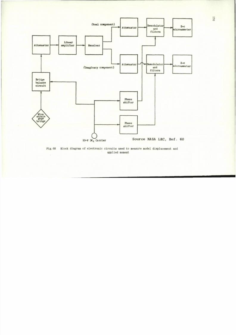
8/10/2019 Techniques for Measurement of Dynamic Stability Derivatives in Ground Test Facilities
http://slidepdf.com/reader/full/techniques-for-measurement-of-dynamic-stability-derivatives-in-ground-test 196/236
Attenuator
.
Bridge
balance
circuit
Linear
amplifier
y>flre\
/
strain X
< gage y
Xbrldge
\S
(Real comp onent)
Resolver
Attenuator
(imaginary component)
Attenuator
Phase
shifter
Phase
shifter
Demodulator
and
filters
D-c
nlcroafflffleter
—
'
W Demodulator
and
filters
D-c
mlcroammeter
05
o
0-V 3K
C
Carrier
Source NASA LRC, Ref. 60
Fig.68 Block diagram of electronic circuits used to measure model displacement and
applied moment
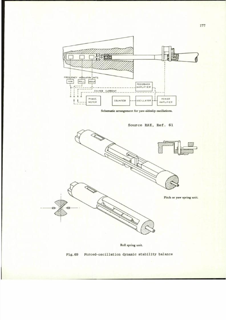
8/10/2019 Techniques for Measurement of Dynamic Stability Derivatives in Ground Test Facilities
http://slidepdf.com/reader/full/techniques-for-measurement-of-dynamic-stability-derivatives-in-ground-test 197/236
177
FP tQ UC NC Y MOTSIJLATtO
VAW 1
r i j
j | ElClTCR CUPBENT
i
Schematic arrangement
for
yaw-sideslip oscillations.
S o u r c e RAE, Ref. 61
Pitch
or
yaw spring unit.
Roll spring unit.
P i g . 6 9 F o r c e d - o s c i l l a t i o n d yn am ic s t a b i l i t y b a l a n c e
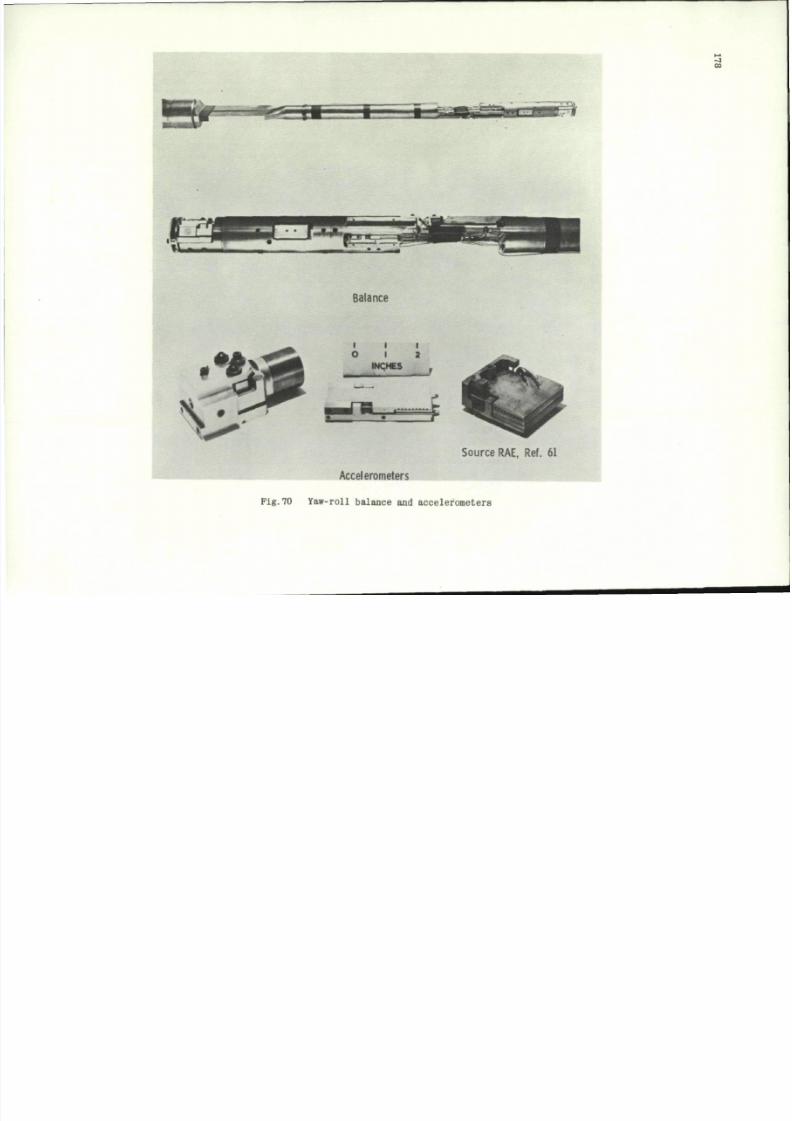
8/10/2019 Techniques for Measurement of Dynamic Stability Derivatives in Ground Test Facilities
http://slidepdf.com/reader/full/techniques-for-measurement-of-dynamic-stability-derivatives-in-ground-test 198/236
- J
00
• r
Balance
t i i
O I 2
INCHES
C
Source RAE, Ref. 61
Accelerometers
Pig.70 Y aw-roll balance and accelerom eters
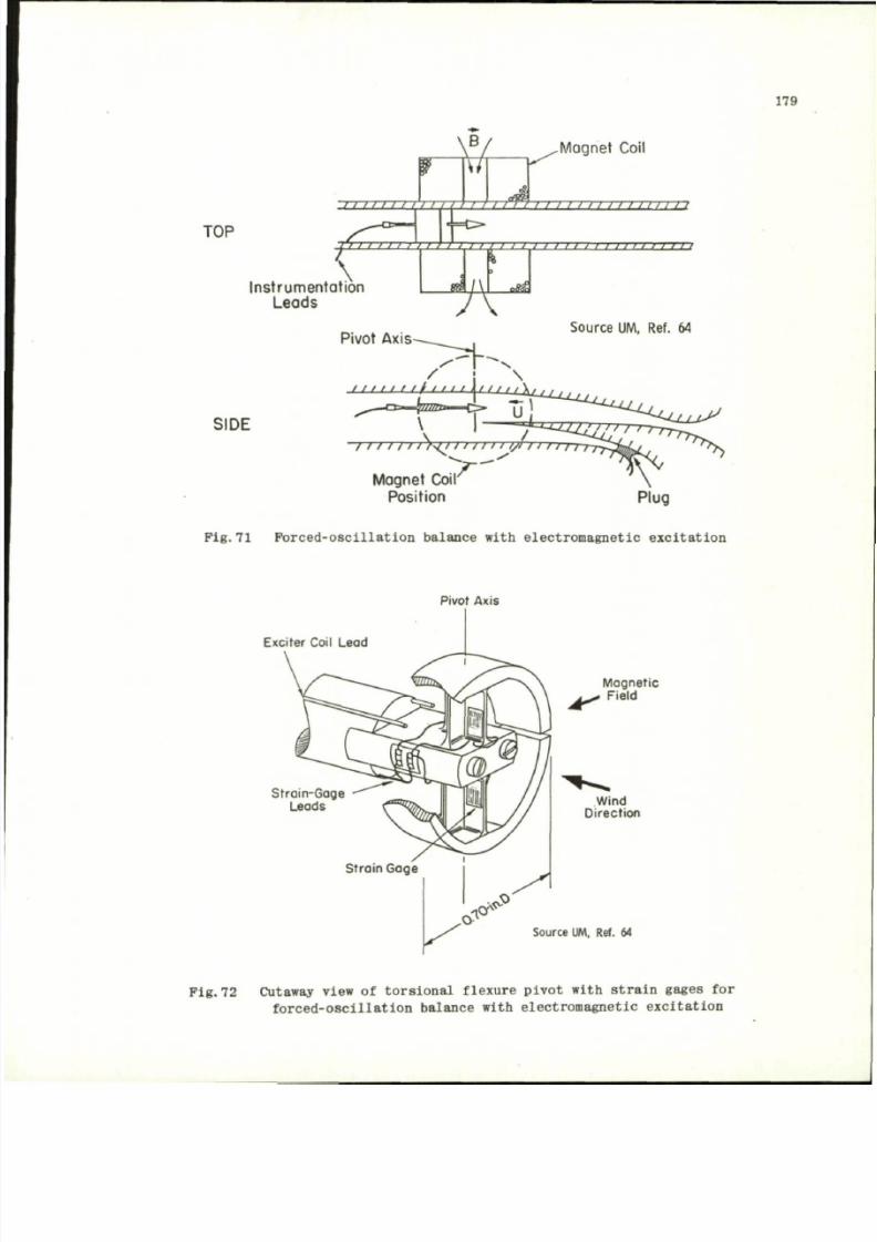
8/10/2019 Techniques for Measurement of Dynamic Stability Derivatives in Ground Test Facilities
http://slidepdf.com/reader/full/techniques-for-measurement-of-dynamic-stability-derivatives-in-ground-test 199/236
179
B
/ / / / / / /
.Mognet Coil
TOP
Ins t rumenta t ion
Leads
V I I I I I > I
mz
i i i i 11 1 11 11 11 1 n
11 J i / i
aM.
i ) i i i i i ) i ) i i ) - m
Pi vo t Ax i s
Source UM, Ref. 64
SIDE
Krr
Coi
Posit ion
Magnet Coir
\....L.7^^
/
-
/ / / / / / / > < / / / / 1 1 1 I /I i > 1 1 1 r r ,
F i g . 7 1 F o r c e d - o s c i l l a t i o n b a l a n ce w i th e l e c t r o m a g n e t i c e x c i t a t i o n
Pivot Axis
Exciter Coil Lead
Strain-Gage
Leads
Magnetic
. Field
Wind
Direction
Source
UM,
Ref. 64
P i g . 7 2 C utaway v iew o f t o r s i o n a l f l ex u r e p i v o t w i t h s t r a i n g ages f o r
f o r c e d - o s c i l l a t i o n b a l an c e w it h e l e c t r o m a g n e t i c e x c i t a t i o n
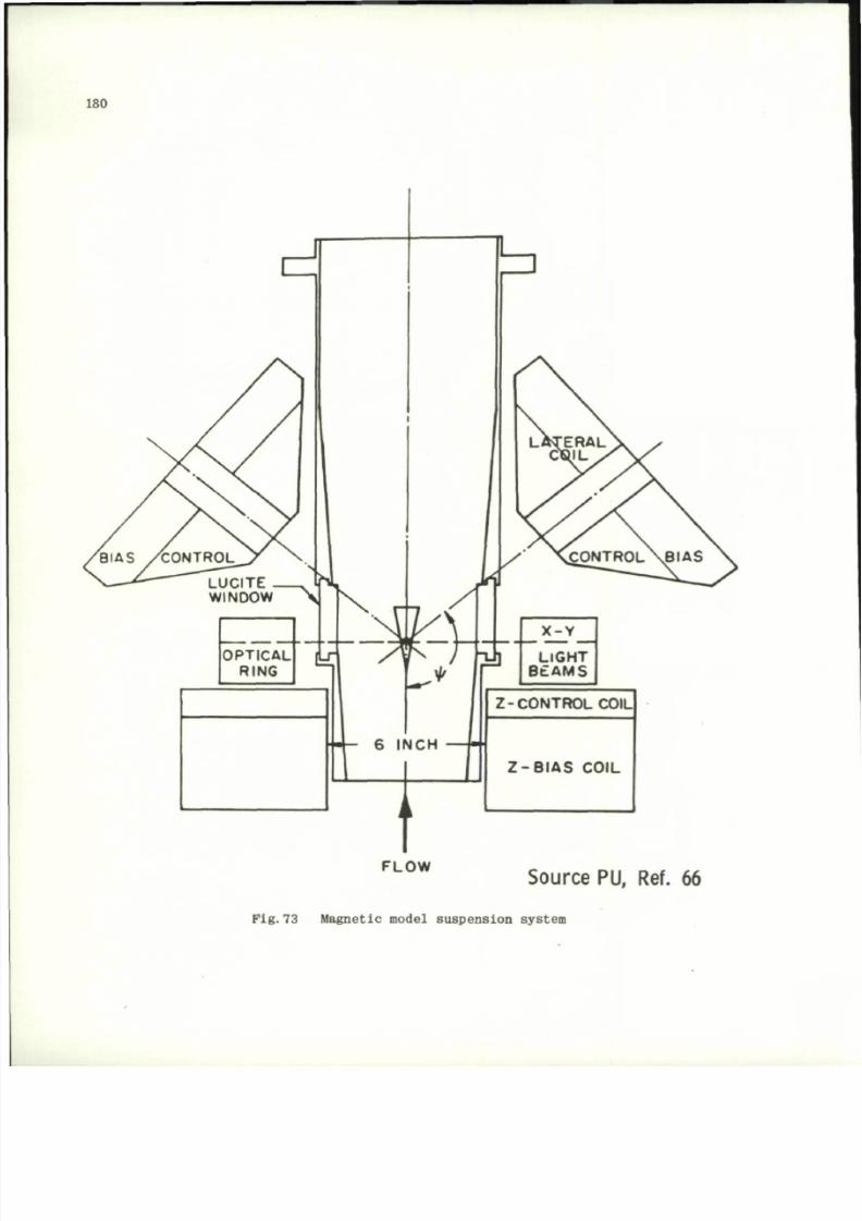
8/10/2019 Techniques for Measurement of Dynamic Stability Derivatives in Ground Test Facilities
http://slidepdf.com/reader/full/techniques-for-measurement-of-dynamic-stability-derivatives-in-ground-test 200/236
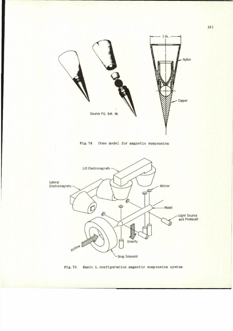
8/10/2019 Techniques for Measurement of Dynamic Stability Derivatives in Ground Test Facilities
http://slidepdf.com/reader/full/techniques-for-measurement-of-dynamic-stability-derivatives-in-ground-test 201/236
181
Source PU, Ref. 66
Nylon
Copper
Pig. 74 Cone model
for
magnetic suspension
Lift Electromagnets
Lateral
Electromagnets
Mirror
Model
^—Light Source
i ^ s ^ ; and Pho toce ll
Drag Solenoid
Pig.75 Basic
L
configuration magnetic suspension system
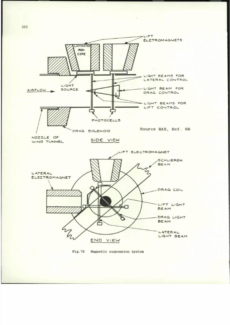
8/10/2019 Techniques for Measurement of Dynamic Stability Derivatives in Ground Test Facilities
http://slidepdf.com/reader/full/techniques-for-measurement-of-dynamic-stability-derivatives-in-ground-test 202/236
182
P H O T O C E L L S
N O Z Z L E OF
W I N D T U N N E L
D R A G S O L E N O I D
SIDE VIEW
L I F T
E L E T R O M A G N E T 5
U G H T S E A M S FOR
L A T E R A L C O N T R O L
L.1GMT
B E A M FOR
D R A G C O N T R O L
L I G H T B E A M S FOR
L I F T C O N T R O L
Sourc e RAE, Ref. 68
I F T E L E C T R O M A G N E T
L A T E R A L
E L E C T R O M A G N E T
S C H L I E R E N
BEA.M
D R A G C O i L
L I F T L I G H T
B E A M
D R A G L I G H T
B E A M
L A T E R A L
L I G H T B E A M
END VIEW
Fig.76 Magnetic suspension system
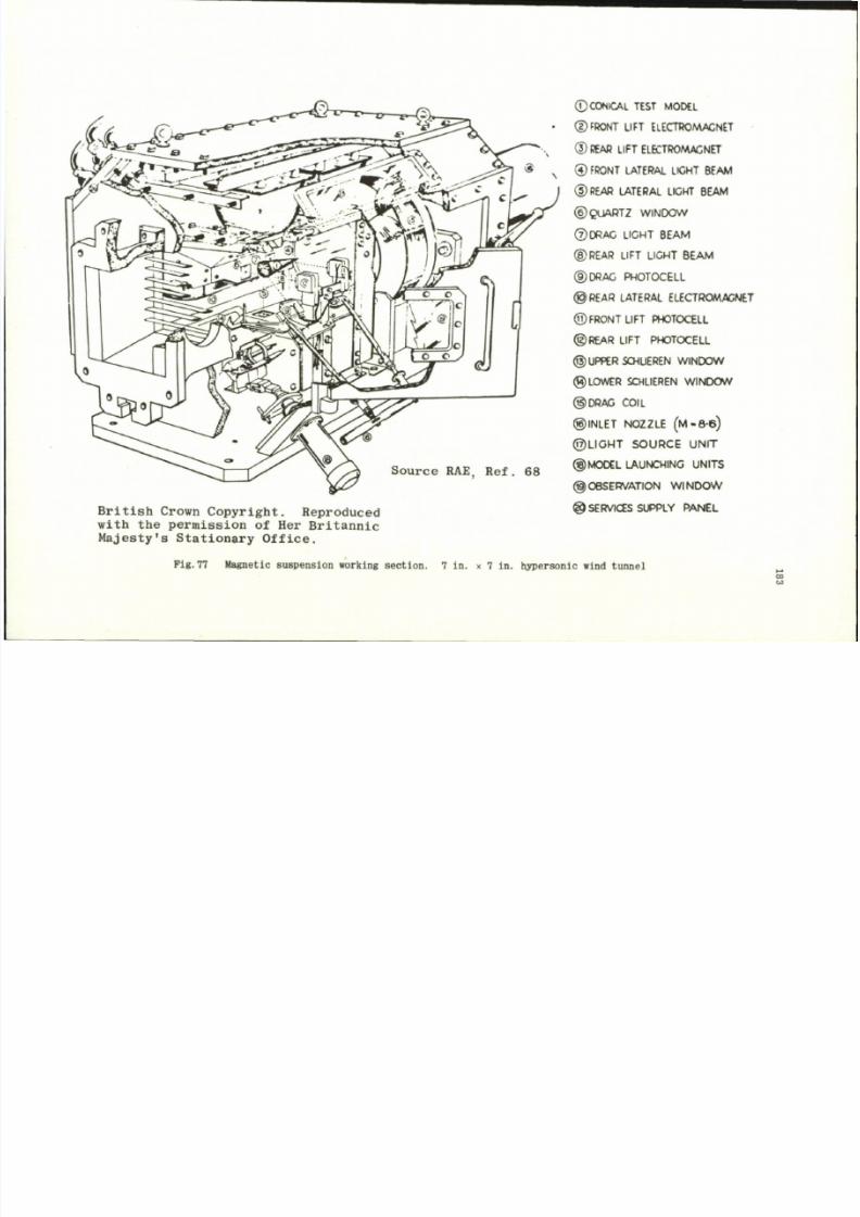
8/10/2019 Techniques for Measurement of Dynamic Stability Derivatives in Ground Test Facilities
http://slidepdf.com/reader/full/techniques-for-measurement-of-dynamic-stability-derivatives-in-ground-test 203/236
Sourc<
British Crown Copyrig ht. Reproduced
with the permi ssion of Her Britannic
Majesty's Stationary Office.
©CONICAL TEST MODEL
©FRONT LIFT ELECTROMAGNET
® REAR LIFT ELECTROMAGNET
® FRONT LATERAL LIGHT BEAM
® REAR LATERAL LIGHT BEAM
©QUARTZ WINDOW
©DRAG LIGHT BEAM
©REAR LIFT LIGHT BEAM
©DRAG PHOTOCELL
©REAR LATERAL ELECTROMAGNET
©FRONT LIFT PHOTOCELL
©R EA R LIFT PHOTOCELL
©UPPER SCHLIEREN WINDOW
©LOWER SCHLIEREN WINDOW
©DRAG COIL
©INLET NOZZLE (lVl -8-6)
©L I G H T SO U R C E U N I T
©MODEL LAUNCHING UNITS
©OBSERVATION WINDOW
@ SERVICES SUPPLY PANEL
Pig .77 Magnetic suspen s ion working sec t io n . 7 in . x 7 in . hyperson ic wind tunn e l
a >
to
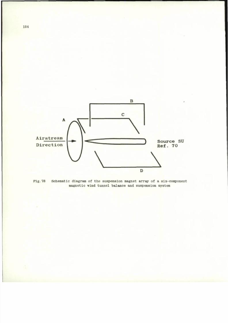
8/10/2019 Techniques for Measurement of Dynamic Stability Derivatives in Ground Test Facilities
http://slidepdf.com/reader/full/techniques-for-measurement-of-dynamic-stability-derivatives-in-ground-test 204/236
184
Airstream
Direction
) Source SU
Ref. 70
\
Pig.78 Schematic diagram of the suspension magnet array of a six-component
magneti c wind tunnel balance and suspension system
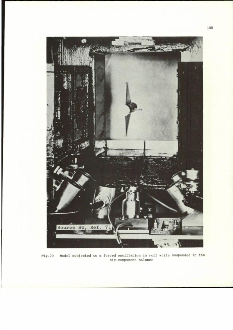
8/10/2019 Techniques for Measurement of Dynamic Stability Derivatives in Ground Test Facilities
http://slidepdf.com/reader/full/techniques-for-measurement-of-dynamic-stability-derivatives-in-ground-test 205/236
185
Fig.79 Model subjected to a forced oscillatio n in roll while suspended in the
six-component balance
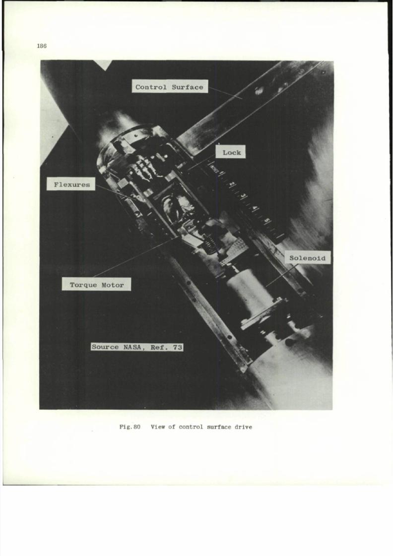
8/10/2019 Techniques for Measurement of Dynamic Stability Derivatives in Ground Test Facilities
http://slidepdf.com/reader/full/techniques-for-measurement-of-dynamic-stability-derivatives-in-ground-test 206/236
186
Pig.80 View of control surface drive
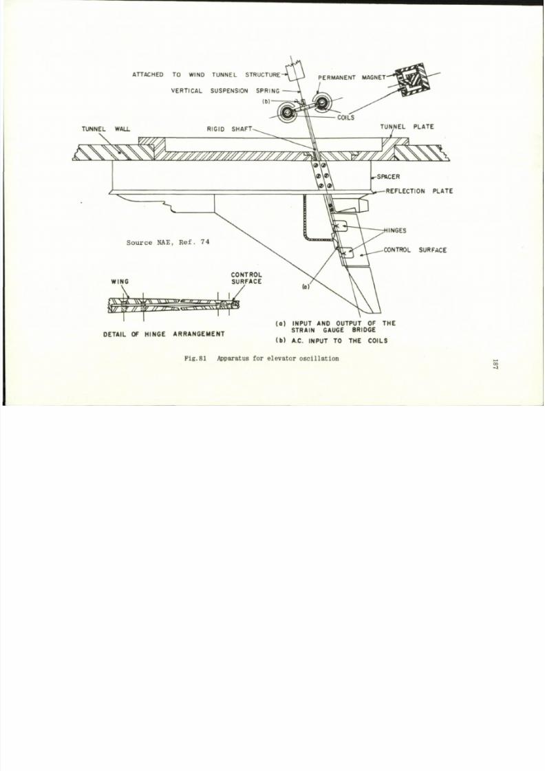
8/10/2019 Techniques for Measurement of Dynamic Stability Derivatives in Ground Test Facilities
http://slidepdf.com/reader/full/techniques-for-measurement-of-dynamic-stability-derivatives-in-ground-test 207/236
ATTACHED TO WIND TUNNE L STRUCTURE
VERTICAL SUSPENSION SPRING
(b)-
.-SRHCER
*•—REFLECTION PLATE
Sour c e NAE, Ref . 74
CONTROL SURFACE
WING
CONTROL
SURFACE
•y » m >> » r — B O P S
t
DETAIL OF HINGE ARRANGEMENT
(o) INPUT AND OUTPUT OF THE
STRAIN GAUGE BRIDGE
(b ) A.C. INPUT TO THE COILS
Pig .81 Apparatus for elevator osc il lation
CO
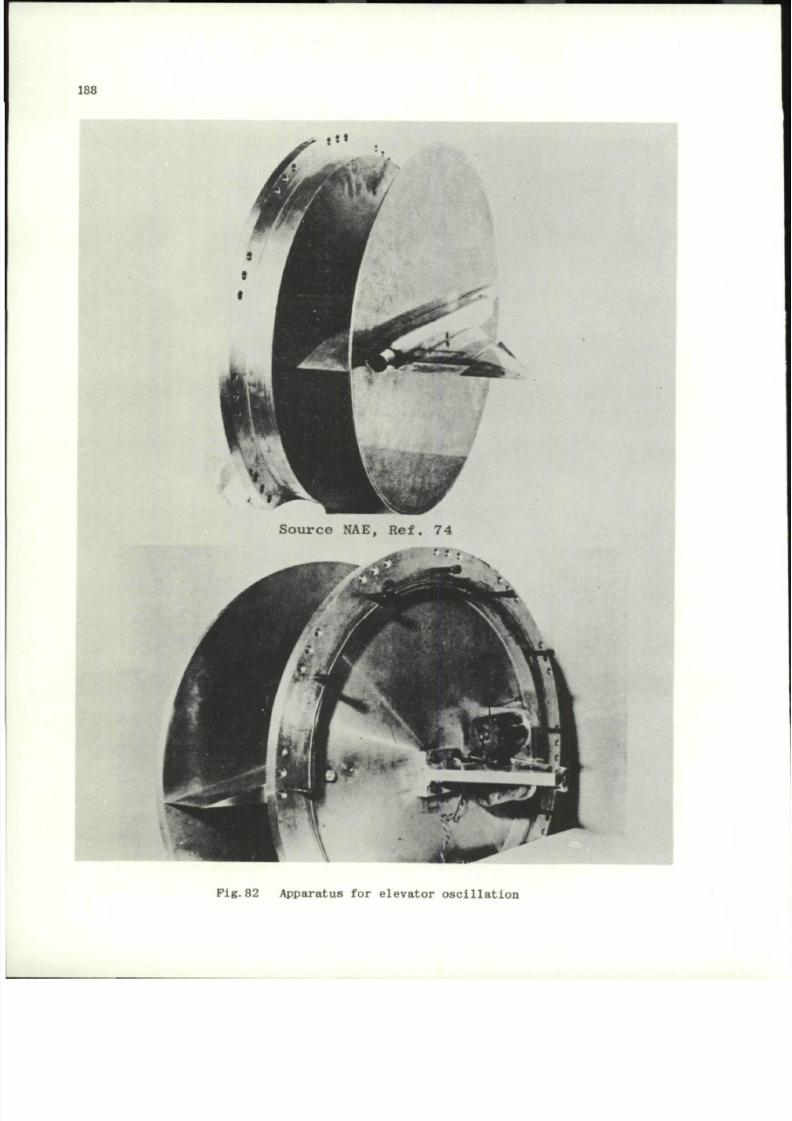
8/10/2019 Techniques for Measurement of Dynamic Stability Derivatives in Ground Test Facilities
http://slidepdf.com/reader/full/techniques-for-measurement-of-dynamic-stability-derivatives-in-ground-test 208/236
188
Fig. 82 Appa ratu s for elevator oscilla tion
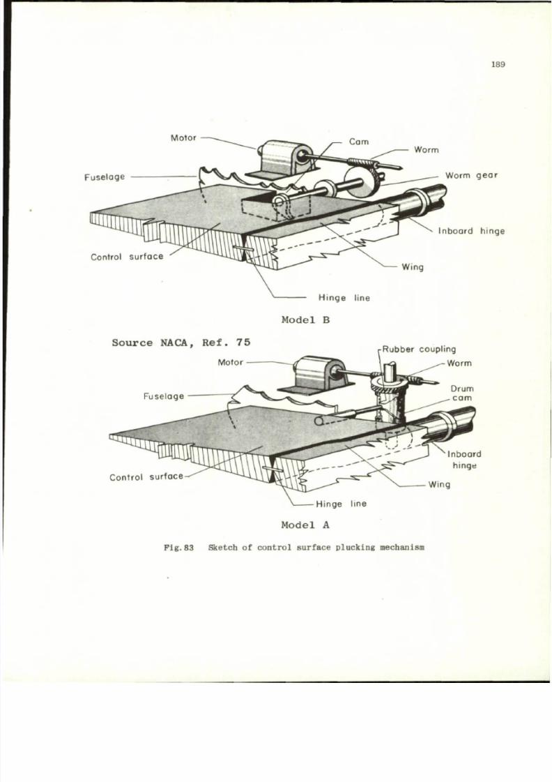
8/10/2019 Techniques for Measurement of Dynamic Stability Derivatives in Ground Test Facilities
http://slidepdf.com/reader/full/techniques-for-measurement-of-dynamic-stability-derivatives-in-ground-test 209/236
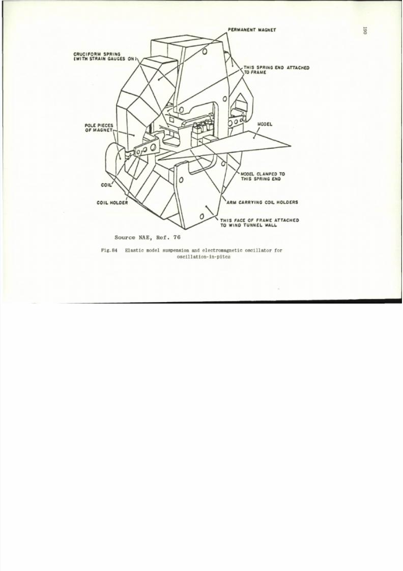
8/10/2019 Techniques for Measurement of Dynamic Stability Derivatives in Ground Test Facilities
http://slidepdf.com/reader/full/techniques-for-measurement-of-dynamic-stability-derivatives-in-ground-test 210/236
PERMANENT MAGNET
CRUCIFORM SPRING
(WITH STRAIN GAUGES ONI
POLE PIECES
O F M A G N E T
COIL'
COIL HOLDER
THIS SPRING END ATTACKED
TO FRAME
MODEL CLAMPED TO
THIS SPRING END
ARM CARRYING COIL HOLDERS
THIS FACE OF FRAME ATTACHED
TO W I N D TU N N E L W A L L
S o u r c e NA E, R e f . 7 6
Pig.84 Elastic model suspension
a nd
electromagnetic oscillator
f o r
osclllation-in-pitcu
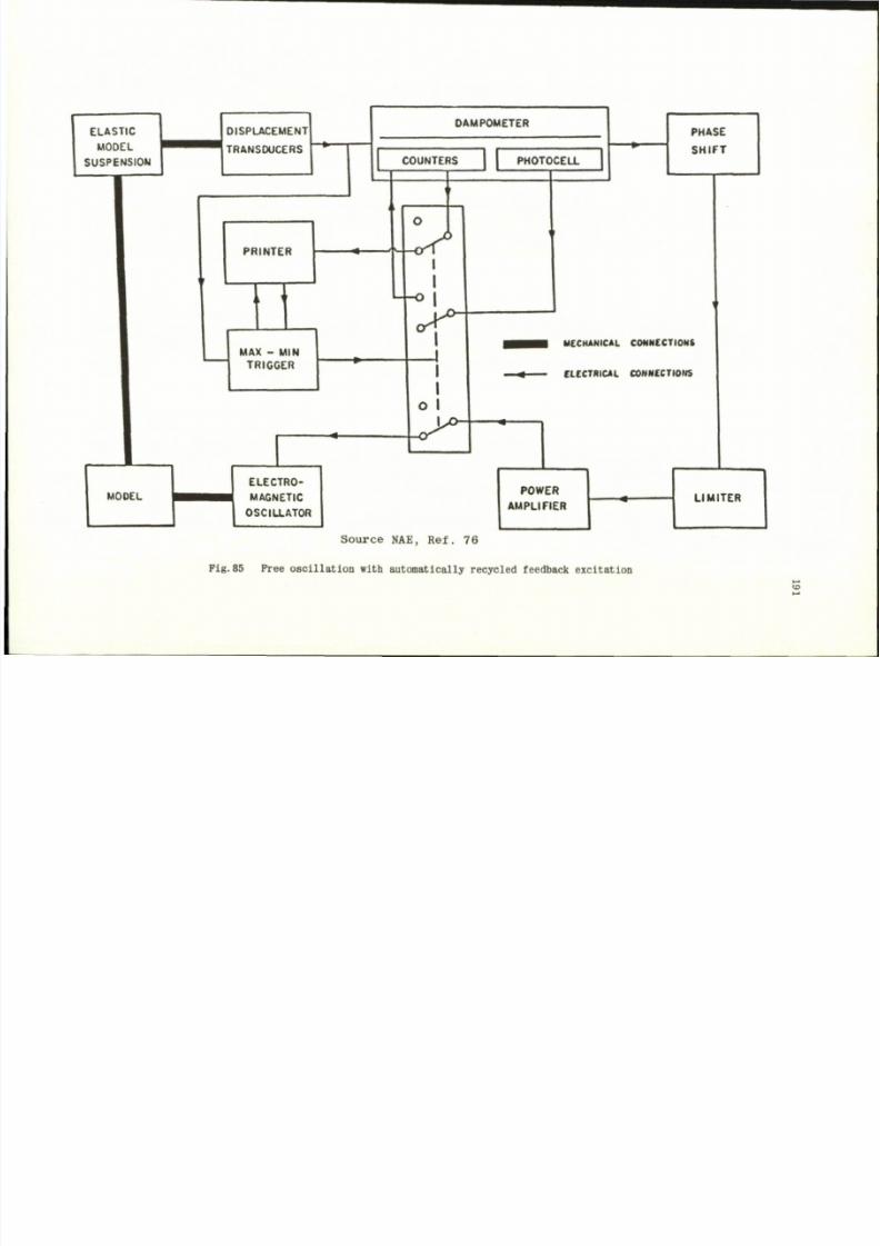
8/10/2019 Techniques for Measurement of Dynamic Stability Derivatives in Ground Test Facilities
http://slidepdf.com/reader/full/techniques-for-measurement-of-dynamic-stability-derivatives-in-ground-test 211/236
ELASTIC
MODEL
SUSPENSION
MODEL
DISPLACEMENT
TRANSDUCERS
PRINTER
I
MAX - MIN
TRIGGER
H
ELECTRO
MAGNETIC
OSCILLATOR
DAMPOMETER
COUNTERS
' ^ - c T
<
o I
W l
P H O TO C ELL
PHASE
SHIFT
MECHANICAL CONNECTIONS
ELECTRICAL CONNECTIONS
POWER
AMPLIFIER
LIMITER
Source NAE, Ref. 76
Pig.85 Free oscillat ion with automatically recycled feedback excitation
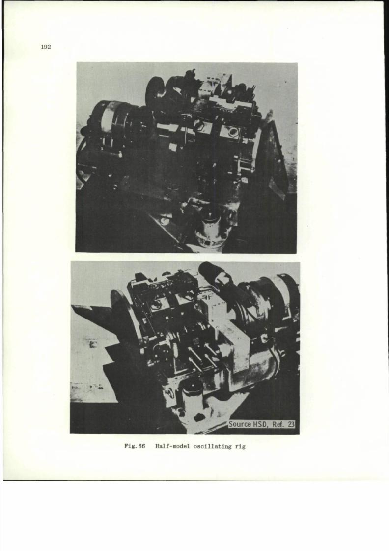
8/10/2019 Techniques for Measurement of Dynamic Stability Derivatives in Ground Test Facilities
http://slidepdf.com/reader/full/techniques-for-measurement-of-dynamic-stability-derivatives-in-ground-test 212/236
192
P i g . 8 6 H a l f- mo d el o s c i l l a t i n g r i g
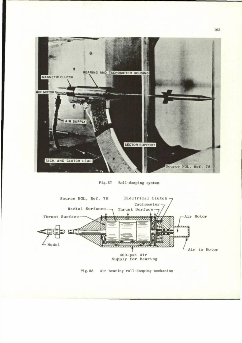
8/10/2019 Techniques for Measurement of Dynamic Stability Derivatives in Ground Test Facilities
http://slidepdf.com/reader/full/techniques-for-measurement-of-dynamic-stability-derivatives-in-ground-test 213/236
193
Source NOL, Ref. 78
* * *
Pig.8 7 Roll-damping system
E l e c t r i c a l C l u t c h
ou rc e NOL, Ref . 79
Tachomete r
R a d i a l S u r f a c e s — . T h r u s t S u r f a c e -
T h r u s t S u r f a c e
4 0 0 - p s i A i r
S u p p l y f o r B e a r i n g
Air Motor
Air to Motor
Fig .88 Air bear ing roll-da mp ing mechanism
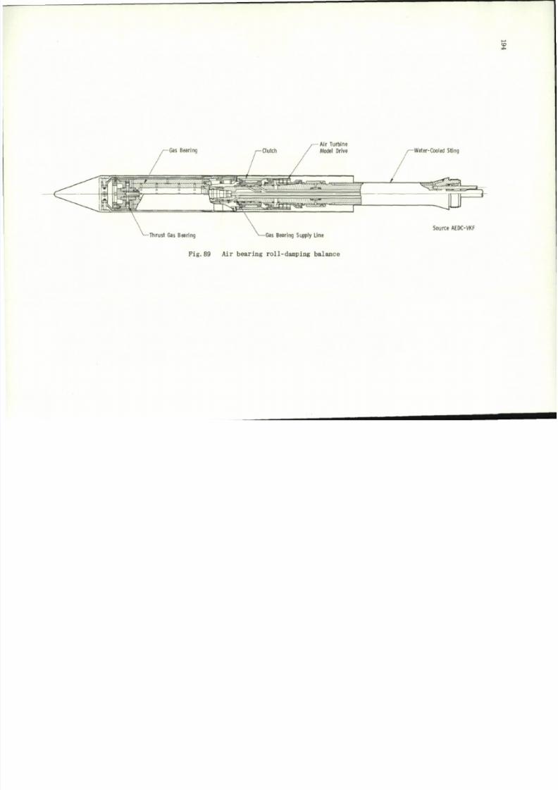
8/10/2019 Techniques for Measurement of Dynamic Stability Derivatives in Ground Test Facilities
http://slidepdf.com/reader/full/techniques-for-measurement-of-dynamic-stability-derivatives-in-ground-test 214/236
a
*.
Air Turb ine
-Thrust Gas Bearing
N
—Gas Bearing Supply Line
Pig.89
Ai r
bearing roll-damping balance
Wafer-Cooled Sting
Source AEDC-VKF
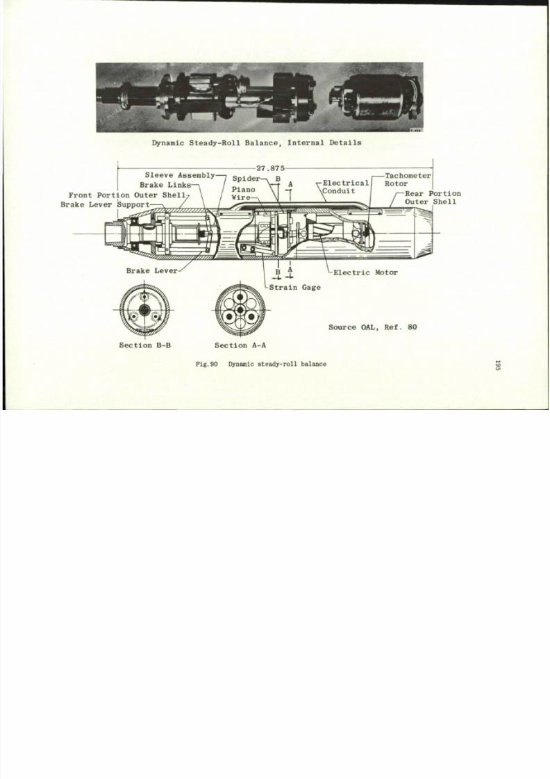
8/10/2019 Techniques for Measurement of Dynamic Stability Derivatives in Ground Test Facilities
http://slidepdf.com/reader/full/techniques-for-measurement-of-dynamic-stability-derivatives-in-ground-test 215/236
D y n a m i c S t e a d y - R o l l B a l a n c e , In t e r na l D e t a i l s
27.875-
S l e ev e A s s e m b l y — ,
S p i d e r B
B r a k e L i n k s —
\
/ _., V- t
A
\ / Piano \ —
t
Front Portion Outer Shell? \ / wire \
Brake Lever Support \ / \
-Tachometer
•Electrical I Rotor
\Condui -—Rear Portion
Outer Shell
Source OAL , Ref. 80
Sectio n B-B Section A-A
Pig .90 Dynamic s te ad y- ro l l ba lance
On
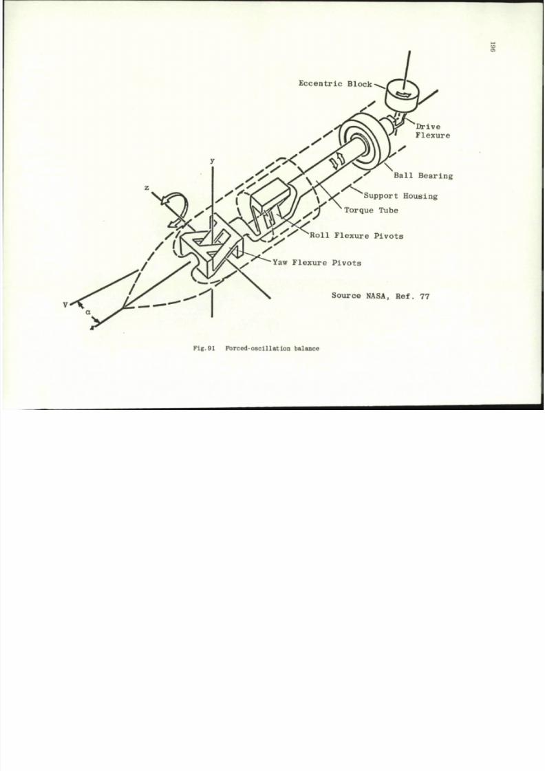
8/10/2019 Techniques for Measurement of Dynamic Stability Derivatives in Ground Test Facilities
http://slidepdf.com/reader/full/techniques-for-measurement-of-dynamic-stability-derivatives-in-ground-test 216/236
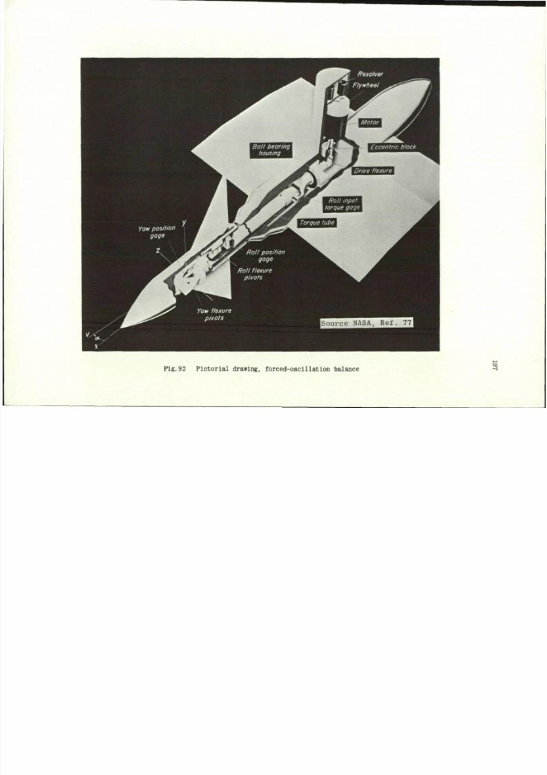
8/10/2019 Techniques for Measurement of Dynamic Stability Derivatives in Ground Test Facilities
http://slidepdf.com/reader/full/techniques-for-measurement-of-dynamic-stability-derivatives-in-ground-test 217/236
Pig.92 Pictor ial drawing, forced-osc illation balance
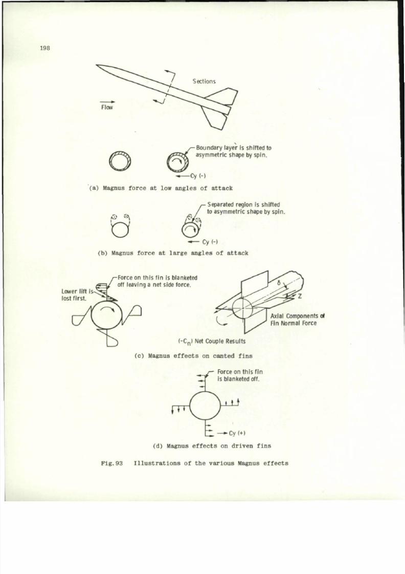
8/10/2019 Techniques for Measurement of Dynamic Stability Derivatives in Ground Test Facilities
http://slidepdf.com/reader/full/techniques-for-measurement-of-dynamic-stability-derivatives-in-ground-test 218/236
198
Sections
Boundary layer
is
shifted
to
asymmetric shape
b y
sp in.
(a) Magnus force
at low
angles
of
attack
( 0 *>>
Separated region is shifted
to asymmetric shape b y sp in.
Cy(-)
(b) Magnus force at large angles of attack
Lower lift is
lost f i rst.
Force on th is f i n i s b lanketed
off leaving
a net
side force.
Axial Components o(
Fin Normal Force
(-C
n
) Net Couple Results
(c) Magnus ef fe ct s on can ted f i n s
_ / — Force on th is f i n
" ^ f
is
blanketed
off.
\ Z . — Cy(+)
(d) Magnus effects
on
drive n fi ns
Pig.93 Illustrations of the various Magnus effects
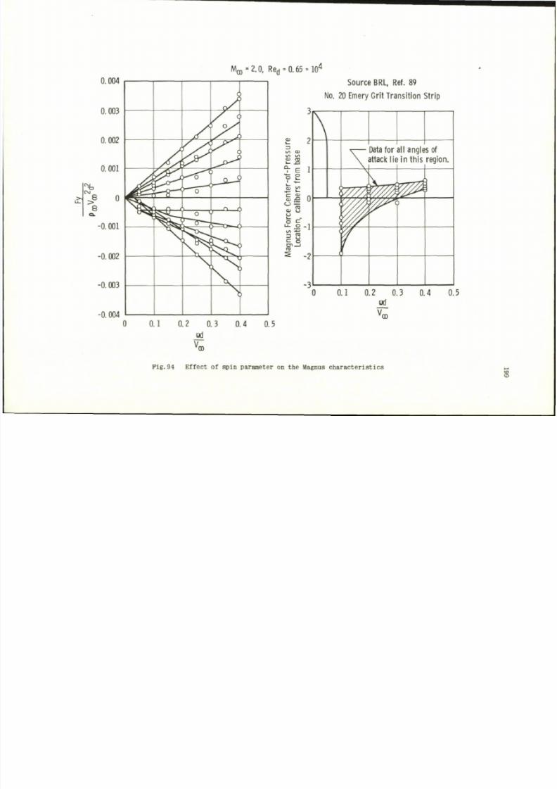
8/10/2019 Techniques for Measurement of Dynamic Stability Derivatives in Ground Test Facilities
http://slidepdf.com/reader/full/techniques-for-measurement-of-dynamic-stability-derivatives-in-ground-test 219/236
M O Q - 2 . 0 , Re
d
=0.65
= 10
4
TD
OO
8
0.004
0.003
0.002
0.001
0
-0.001
-0.002
-0.003
-0.004
L--0-—9
o
j ^ ^ T o .
°y
/
'
Q 6
n r
1
Source BRL,
Ref. 89
No.
20 Emery Grit Transition Strip
</) <m>
< / • > on
o> co
> - -C
^
E
•S
£
S 0
D - Q
CL >
(J
u
£ c
^ CD
C o
C O
-2
\
r^///i
Data
for all
angles
of
attack
lie in
this region.
p ^
0 0.1 0.2 0.3 0.4 0.5
V
0D
0 0.1 0.2 0.3 0.4 0.5
Fig.94 Effect of spin p arameter on the Magnus characteristics
to
CD
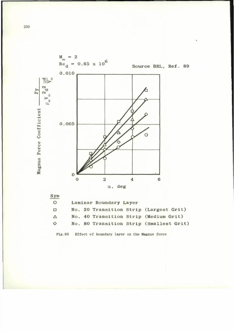
8/10/2019 Techniques for Measurement of Dynamic Stability Derivatives in Ground Test Facilities
http://slidepdf.com/reader/full/techniques-for-measurement-of-dynamic-stability-derivatives-in-ground-test 220/236
200
a
T}\ 8
3 \ >
eg
CM
8
>
8
Q .
a
o
o
o
o
ml
o
o
S o
Cm
M = :
0 0
Re , =
a
0 . 0 1 0
0 . 6 5 x 1 0 '
S o u rc e BRL, Re f . 89
0 . 0 0 5
0
H _
a
Sym
O
D
A
O
d e g
Laminar Boundary Layer
No. 20 T r a n s i t i o n S t r i p ( L a r g e s t G r i t )
No.
40 T r a n s i t i o n S t r i p (M edium G r i t )
No. 80 T r a n s i t i o n S t r i p ( S m a l l e s t G r i t )
Fi g. 95 Eff ect of boundary la ye r on th e Magnus for ce
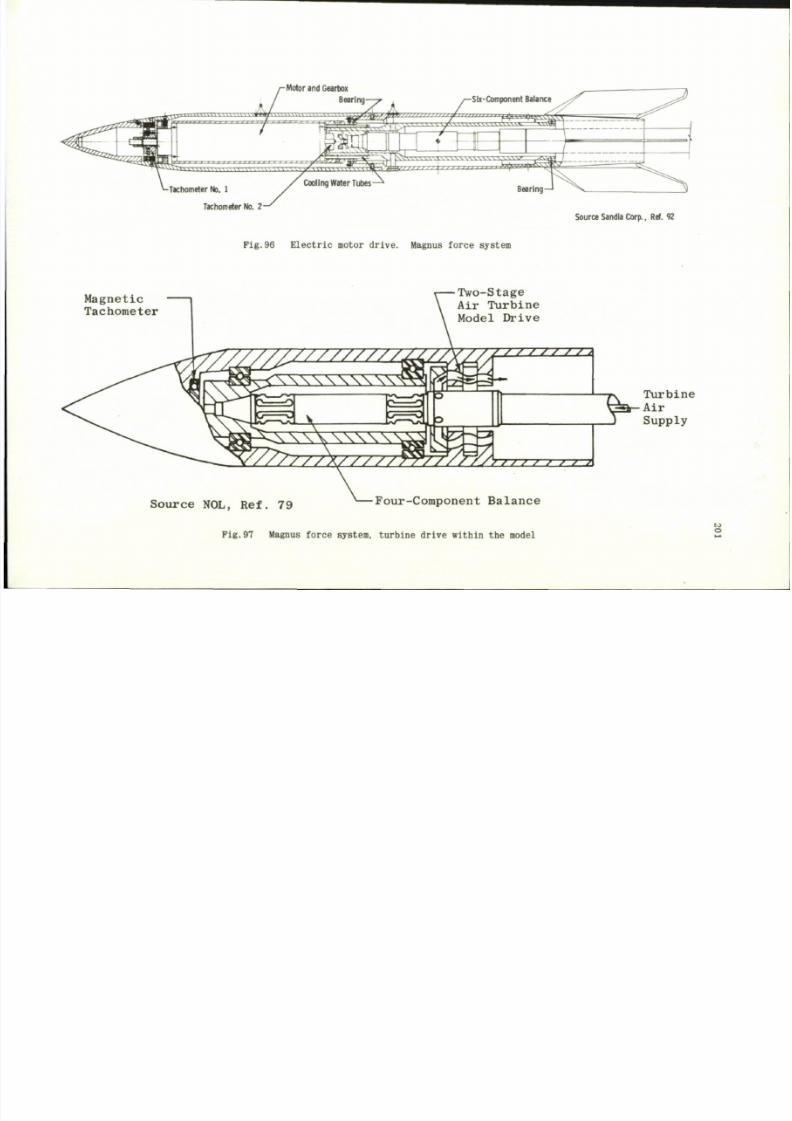
8/10/2019 Techniques for Measurement of Dynamic Stability Derivatives in Ground Test Facilities
http://slidepdf.com/reader/full/techniques-for-measurement-of-dynamic-stability-derivatives-in-ground-test 221/236
-Tachometer No. 1
Tachometer
No. 2 -
Pig.96 Electric motor drive. Magnus force system
Source Sandia Corp., Ref.
92
Magnetic
Tachometer
zzzzzzzzz
\\\w
/ / / /
Two-Stage
Air Turbine
Model Drive
z / / / / / z :
/
/ \ * / ; / / , > / / >
S-
Turbine
Air
Supply
Source NO L, Ref. 79
F o u r - C o m p o n e n t B a l a n c e
Fig .97 Magnus forc e system, turb in e dr iv e wi thin the model
w
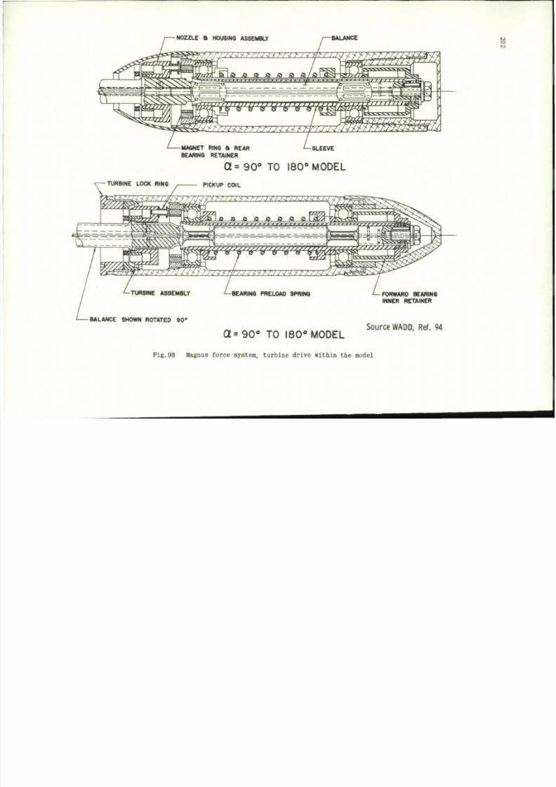
8/10/2019 Techniques for Measurement of Dynamic Stability Derivatives in Ground Test Facilities
http://slidepdf.com/reader/full/techniques-for-measurement-of-dynamic-stability-derivatives-in-ground-test 222/236
NOZZLE a HOUSING ASSEMBLY
BALANCE
^^^mm^m
wmmzM
T—-TURBINE
URBINE LOCK RING
[ZZZZ3£
" " " { ' " " " " " " " - * •
MAGNET RING S REAR <— SLEEVE
BEARING RETAINER
Q= 90° TO 180° MODEL
PICKUP COIL
t. a a a a a
G
w^vvwr
J J t W / J J U f - M J j m - r - r
BEARING PRELOAD SPRING
BALANCE SHOWN ROTATED 9 0*
a =90° TO 180° MODEL
FORWARD BEARING
INNER RETAINER
Source
WADD, Ref. 94
to
Pig.98 Magnus force system, turbine drive within
the
model
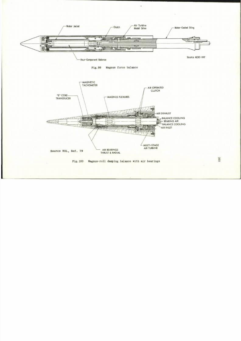
8/10/2019 Techniques for Measurement of Dynamic Stability Derivatives in Ground Test Facilities
http://slidepdf.com/reader/full/techniques-for-measurement-of-dynamic-stability-derivatives-in-ground-test 223/236
Air Turbine
Model Drive
•Four-Component Balance
Fig.99 Magnus force balance
Water-Cooled Sting
Source AEDC-VKF
"E "
C O R E -
TRANSDUCER
-M A G N E T IC
TACHOMETER
AIR OPERATED
CLUTCH
-AIR EXHAUST
'mm-BALANCE COOLING
i - BEARING AIR
' ^ B A L A N C E C O O L I N G
^AIR INLET
Source NOL, Ref. 79
AIR BEARINGS
THRUST & RADIAL
MULTI-STAGE
AIR TURBINE
Pig .100 Magnus-ro l l damping ba lance wi th a i r bear i ngs
M
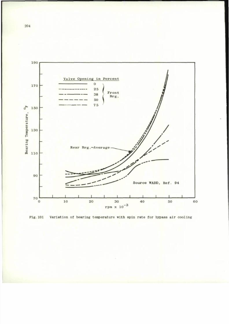
8/10/2019 Techniques for Measurement of Dynamic Stability Derivatives in Ground Test Facilities
http://slidepdf.com/reader/full/techniques-for-measurement-of-dynamic-stability-derivatives-in-ground-test 224/236
204
190
170
o" 150
S
u
3
4->
a
u
01
| 130
5
H
M
e
•
tl
CO
a
« 110
90
70
Valve Opening in Percent
J
L
J
L
Source WADD, Ref. 94
J
I I L
10 20 30
rpm x 10"
40
50
60
Pig.101 Variation of bearing temperature with spin rate for bypass air cooling
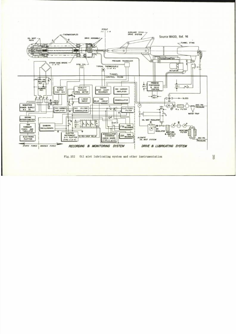
8/10/2019 Techniques for Measurement of Dynamic Stability Derivatives in Ground Test Facilities
http://slidepdf.com/reader/full/techniques-for-measurement-of-dynamic-stability-derivatives-in-ground-test 225/236
SCALE
OIL MIST
PATH
Source WADD.
Ref. 94
-TUNNEL STINO
STRAIN GAGE BRIDGE
(I
of 4)
€_.—k
RPM COIL
TYPICAL THERMOCOUPLE
®
(
>t4
'
T U N N E L
M
n u
&
D
»
CONTROL ROOM
POWER
SUPPLY
JK C 10V
, M f t f l TT 9 i » °
A
TRON ' H |» W-
SUPPLY ? r r r ;
NOBATRON
POWER SUPPLY
6 V DC
SKC CARRCR
AMPLIFIER
BROWN
POTENTIOMETER
X
r
J
IBM
SUMMARY
PUNCH AND
TABULATOR
SANBORN
OSCILLOGRAPH
HEWLETT
PACKARD
- | FREQ. METER
9** " *
V f 4
LINEAR
SWEEP
**
SKC VOLTAGE
DEMODULATOR
1 P
110 »
6 0 -
1R0WN
STRIP CHART
RECORDER
CEC CARRIER
AMPLIFIER
TIME
DELAY CIRCUT
DEMODULATOR
PREBEND
POSITIONING
B DRIVE
CONTROL
MO v
« 0 -
L 8 E E B
T^frj
ELECTRONIC
PLOTTER
ELECTRO
INSTRUMENT
X- Y PLOTTER
(TYPJ (I of 4 )
TO PEN DROP RELAY
r ^ « "
ELECTRONIC
FILTER
-o*-d
%
1200 PSI
PRESSURE
CM
TAPE
~W I RECORDER
OIL M IST REGULATOR
WATER TRAP
DEMODULATOR
OVERDRIVE
CHECK SCOPE
(TYP.) (I of 4)
5
1
^ " R E C O R D E R
0
AIR
REGULATOR
^H2f
ALEWTE
OIL HIST SYSTEH
MOISTURE [
MOISTURE FILTER
A PARTICLE
FILTER
PRESSURE
STATIC FORCE | UAONUS FO RCE
RECORDING
8 MONITORING SYSTEM
DRIVE
8 LUBRICATING SYSTEM
Fig.102
Oil mist lubricatin g system and other instrumentation
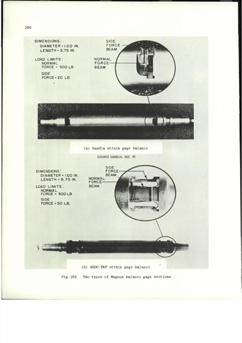
8/10/2019 Techniques for Measurement of Dynamic Stability Derivatives in Ground Test Facilities
http://slidepdf.com/reader/full/techniques-for-measurement-of-dynamic-stability-derivatives-in-ground-test 226/236
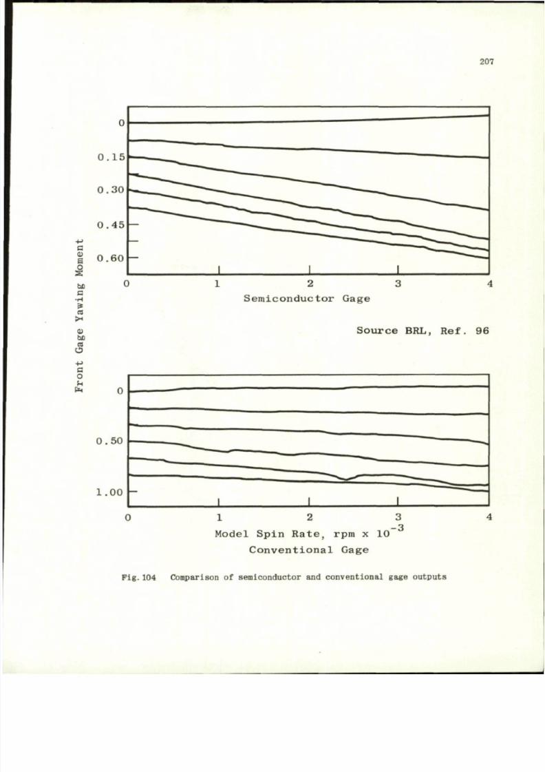
8/10/2019 Techniques for Measurement of Dynamic Stability Derivatives in Ground Test Facilities
http://slidepdf.com/reader/full/techniques-for-measurement-of-dynamic-stability-derivatives-in-ground-test 227/236
207
Cm
> 4
< U
bD
a
O
+ - >
a
o
u
0 . 5 0
1.00 -
Semic onductor Gage
Sourc e BRL, Ref. 96
—
1
_^22
— - * ^ - ,.
1 1
1 2
M o d e l S p i n R a t e , rpm x 10
C o n v e n t i o n a l G a g e
3
- 3
4
Fig.104 Comparison of semiconductor and conventional gage outputs

8/10/2019 Techniques for Measurement of Dynamic Stability Derivatives in Ground Test Facilities
http://slidepdf.com/reader/full/techniques-for-measurement-of-dynamic-stability-derivatives-in-ground-test 228/236
208
be
0)
X3
be
c
<
ca
S
a,
120
110
100
9 0
8 0
7 0
6 0
50
4 0
3 0
2 0
10
0
1
' I ' I I | I I I
S o u r c e , R e f . 1 0 4
1 0 0
I
. 1 . 1
I I M I I
2 0 0 4 0 0
F r e q u e n c y , f, c p s
7 0 0
Pig.105 Experimental response magnitude and phas e-ang le ca li br at io n for 1.38 in. of
0.030 in. nominal-diameter tubing connected to a gage volume of 0.02 cu.in.
fo r a i r a t sea- level condi t ions
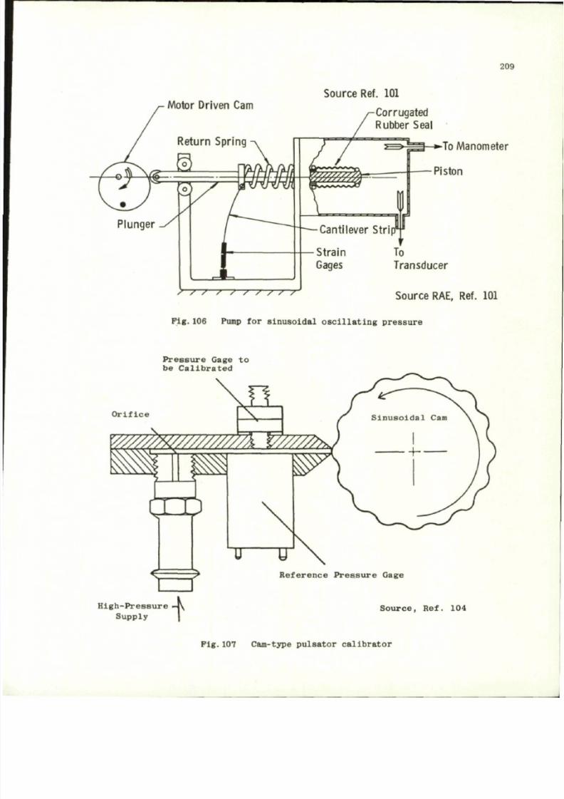
8/10/2019 Techniques for Measurement of Dynamic Stability Derivatives in Ground Test Facilities
http://slidepdf.com/reader/full/techniques-for-measurement-of-dynamic-stability-derivatives-in-ground-test 229/236
209
Motor Driven Cam
Return Spring
Source Ref. 101
Plunger
Corrugated
Rubber Seal
To Manometer
Piston
/ / s / / / / / /
Source RAE, Ref. 101
F i g .1 0 6 Pump f o r s i n u s o i d a l o s c i l l a t i n g p r e s s u r e
P r e s s u r e G a g e t o
b e C a l i b r a t e d
O r i f i c e
- ^
y//////w/////////7rmr.
H ™
N
r
1
R e f e r e n c e P r e s s u r e G a g e
H i g h - P r e s s u r e
S u p p l y
So ur ce , Ref . 104
P i g .1 0 7 Cam -ty pe p u l s a t o r c a l i b r a t o r
8/10/2019 Techniques for Measurement of Dynamic Stability Derivatives in Ground Test Facilities
http://slidepdf.com/reader/full/techniques-for-measurement-of-dynamic-stability-derivatives-in-ground-test 230/236
D I S T R I B U T I O N
Copies o f AGARD publications m a y b e obtained in the
various countries
at the
addresse s given below.
On peut se procurer de s exemplaires des publications
de 1' AGA RD
aux
adresses suivantes.
BELGIUM
BELGIQUE
Centre National
d'
Etudes
et de
Recherches
Aeronautiques
11, rue
d'Egmont, Bruxelles
CANADA Director
of
Scientific Information S ervice
Defense Research Board
Department
of
National Defense
"A" Building, Ottawa, Ontario
DENMARK
DANEMARK
Danish Defence Research Board
0sterbrogades Kaseme
Copenhagen 0
FRANCE
O.N.E.R.A.
(Direction)
25 avenue d e l a Division Leclerc
92 C hatillon-sous-Bagneux
GERMANY
ALLEMAGNE
Zentralstelle
fur
Luftfahr tdokumentation
und Information
Maria-Theresia Str.21
8 MUnchen 27
At tn : Dr Ing . H . J .R au te nbe rg
GREECE
GRECE
Greek National Defence Staff
D.JSG,
Athens
ICELAND
ISLANDS
Director
of
Aviation
c/o Plugrad
Reykj
avik
ITALY
ITALIE
Ufflcio
del
Delegate Nazionale
all'
AGARD
Ministero Difesa
-
Aeronautica
Roma
LUXEMBURG
LUXEMBOURG
Obtainable through Belgium
NETHERLANDS
PAYS
BAS
Netherlands Delegation to AGARD
c/o National Aerospace Laboratory
NLR
Attn: M r
A.H.Geudeker
P.O.Box 126
Delft
8/10/2019 Techniques for Measurement of Dynamic Stability Derivatives in Ground Test Facilities
http://slidepdf.com/reader/full/techniques-for-measurement-of-dynamic-stability-derivatives-in-ground-test 231/236
NORWAY
NORVEGE
Norway Defence Research Establishment
P.O.Box 25
Kjeller
Attn:
M r O.Blichner
PORTUGAL Diraccao do Servigo de Material
da Porca Aerea
Rua d a Escola Politecnica 42
Lisboa
Attn:
Brig.
Gen. J.Pereira
do
Nascimento
TURKEY
TURQUIE
Turkish Delegation
to
NATO
North Atlantic Treaty Organisation
Brussels 39, Belgium
Attn: AGARD National Delegate
UNITED KINGDOM
ROYAUME UNI
Ministry of Technology
T.I.L.(E) Room 401
Block A, Station Square House
St.
Mary Cray
Orpington, Kent
UNITED STATES
ETATS UNIS
National Aeronautics and Space Administration
Langley Field, Virginia
Attn:
Report Distribution and Storage Unit
*
Pr in t ed by Techn ica l Ed i t i ng and Reproduc t ion L td
Harford House, 7-9 Ch ar l o t te S t . London , V. l .

8/10/2019 Techniques for Measurement of Dynamic Stability Derivatives in Ground Test Facilities
http://slidepdf.com/reader/full/techniques-for-measurement-of-dynamic-stability-derivatives-in-ground-test 232/236
8/10/2019 Techniques for Measurement of Dynamic Stability Derivatives in Ground Test Facilities
http://slidepdf.com/reader/full/techniques-for-measurement-of-dynamic-stability-derivatives-in-ground-test 233/236

8/10/2019 Techniques for Measurement of Dynamic Stability Derivatives in Ground Test Facilities
http://slidepdf.com/reader/full/techniques-for-measurement-of-dynamic-stability-derivatives-in-ground-test 234/236

8/10/2019 Techniques for Measurement of Dynamic Stability Derivatives in Ground Test Facilities
http://slidepdf.com/reader/full/techniques-for-measurement-of-dynamic-stability-derivatives-in-ground-test 235/236

8/10/2019 Techniques for Measurement of Dynamic Stability Derivatives in Ground Test Facilities
http://slidepdf.com/reader/full/techniques-for-measurement-of-dynamic-stability-derivatives-in-ground-test 236/236