techniques for understanding legacy software systems
TRANSCRIPT

Techniques for Understanding LegacySoftware Systems

About the cover: A man unreels in front of him a portion of a reel of punched pa-per tape. A B220 computer installation can be seen in the background behind him.Picture from the Burroughs Corporation Collection (CBI 90), Charles BabbageInstitute, University of Minnesota, Minneapolis.
The work reported in this thesis has been carried out at the Center for Mathemat-ics and Computer Science (CWI) in Amsterdam under the auspices of the researchschool IPA (Institute for Programming research and Algorithmics). The publi-cation of this thesis was made possible in part through support of the SoftwareImprovement Group.

Techniques for Understanding Legacy Software Systems
ACADEMISCH PROEFSCHRIFT
ter verkrijging van de graad van doctoraan de Universiteit van Amsterdamop gezag van de Rector Magnificus
prof. mr. P. F. van der Heijdenten overstaan van een door het
college voor promoties ingestelde commissie,in het openbaar te verdedigen
in de Aula der Universiteitop dinsdag 26 februari 2002, te 10.00 uur
door Tobias Kuipersgeboren te Vleuten, Nederland

Promotor: Prof. dr. P. KlintCopromotor: Dr. A. van DeursenFaculteit: Faculteit der Natuurwetenschappen, Wiskunde en Informatica

Contents
Preface 9
1 Introduction 131.1 Maintaining Legacy Systems . . . . . . . . . . . . . . . . . . . . 14
1.1.1 Software Engineering for Maintenance . . . . . . . . . . 151.2 Changing Legacy Systems . . . . . . . . . . . . . . . . . . . . . 17
1.2.1 Minor Change . . . . . . . . . . . . . . . . . . . . . . . 181.2.2 Structural Change . . . . . . . . . . . . . . . . . . . . . . 18
1.3 Research Questions . . . . . . . . . . . . . . . . . . . . . . . . . 191.4 Reader’s Roadmap . . . . . . . . . . . . . . . . . . . . . . . . . 21
2 Rapid System Understanding 232.1 Introduction . . . . . . . . . . . . . . . . . . . . . . . . . . . . . 232.2 Tool Architecture . . . . . . . . . . . . . . . . . . . . . . . . . . 242.3 Cases Investigated . . . . . . . . . . . . . . . . . . . . . . . . . . 252.4 Collected Data . . . . . . . . . . . . . . . . . . . . . . . . . . . 26
2.4.1 System inventory . . . . . . . . . . . . . . . . . . . . . . 262.4.2 Program call graph . . . . . . . . . . . . . . . . . . . . . 272.4.3 Database usage . . . . . . . . . . . . . . . . . . . . . . . 272.4.4 Field usage . . . . . . . . . . . . . . . . . . . . . . . . . 292.4.5 Section call graph . . . . . . . . . . . . . . . . . . . . . . 312.4.6 Further experiments . . . . . . . . . . . . . . . . . . . . 32
2.5 Interpreting Analysis Results . . . . . . . . . . . . . . . . . . . . 322.5.1 Understanding copybooks . . . . . . . . . . . . . . . . . 322.5.2 Call graph and reusability . . . . . . . . . . . . . . . . . 332.5.3 Understanding data usage . . . . . . . . . . . . . . . . . 342.5.4 Reusability assessment . . . . . . . . . . . . . . . . . . . 34
2.6 Related Work . . . . . . . . . . . . . . . . . . . . . . . . . . . . 352.7 Conclusions . . . . . . . . . . . . . . . . . . . . . . . . . . . . . 362.8 Future Work . . . . . . . . . . . . . . . . . . . . . . . . . . . . . 37

6 CONTENTS
3 Building Documentation Generators 393.1 Introduction . . . . . . . . . . . . . . . . . . . . . . . . . . . . . 393.2 Source Code Analysis . . . . . . . . . . . . . . . . . . . . . . . . 41
3.2.1 Lexical analysis . . . . . . . . . . . . . . . . . . . . . . . 413.2.2 Syntactic Analysis . . . . . . . . . . . . . . . . . . . . . 423.2.3 Island Grammars . . . . . . . . . . . . . . . . . . . . . . 433.2.4 Parse Tree Analysis . . . . . . . . . . . . . . . . . . . . . 45
3.3 Extracting Documentation . . . . . . . . . . . . . . . . . . . . . 453.3.1 Manual versus Automated Extraction . . . . . . . . . . . 453.3.2 System Decomposition . . . . . . . . . . . . . . . . . . . 463.3.3 Aggregation and Use Relations . . . . . . . . . . . . . . 463.3.4 System and Subsystem Partitioning . . . . . . . . . . . . 473.3.5 Program Descriptions . . . . . . . . . . . . . . . . . . . . 473.3.6 Section Descriptions . . . . . . . . . . . . . . . . . . . . 473.3.7 Batch Job Dependencies . . . . . . . . . . . . . . . . . . 48
3.4 Presenting Documentation . . . . . . . . . . . . . . . . . . . . . 493.5 Business Case . . . . . . . . . . . . . . . . . . . . . . . . . . . . 50
3.5.1 Background . . . . . . . . . . . . . . . . . . . . . . . . . 503.5.2 Documentation Wishes . . . . . . . . . . . . . . . . . . . 513.5.3 Derived Documentation . . . . . . . . . . . . . . . . . . 513.5.4 Evaluation . . . . . . . . . . . . . . . . . . . . . . . . . 53
3.6 Concluding Remarks . . . . . . . . . . . . . . . . . . . . . . . . 54
4 Identifying Objects using Cluster and Concept Analysis 574.1 Introduction . . . . . . . . . . . . . . . . . . . . . . . . . . . . . 574.2 Related Work . . . . . . . . . . . . . . . . . . . . . . . . . . . . 594.3 Field and Program Selection . . . . . . . . . . . . . . . . . . . . 604.4 Cluster analysis . . . . . . . . . . . . . . . . . . . . . . . . . . . 61
4.4.1 Overview . . . . . . . . . . . . . . . . . . . . . . . . . . 614.4.2 Experimental Testbed . . . . . . . . . . . . . . . . . . . . 644.4.3 Experiments . . . . . . . . . . . . . . . . . . . . . . . . 654.4.4 Assessment . . . . . . . . . . . . . . . . . . . . . . . . . 67
4.5 Concept Analysis . . . . . . . . . . . . . . . . . . . . . . . . . . 684.5.1 Basic Notions . . . . . . . . . . . . . . . . . . . . . . . . 684.5.2 Experimental Testbed . . . . . . . . . . . . . . . . . . . . 704.5.3 Experiments . . . . . . . . . . . . . . . . . . . . . . . . 70
4.6 Clustering and Concepts Compared . . . . . . . . . . . . . . . . 724.7 Object Identification . . . . . . . . . . . . . . . . . . . . . . . . 744.8 Concluding Remarks . . . . . . . . . . . . . . . . . . . . . . . . 76
4.8.1 Acknowledgments . . . . . . . . . . . . . . . . . . . . . 76
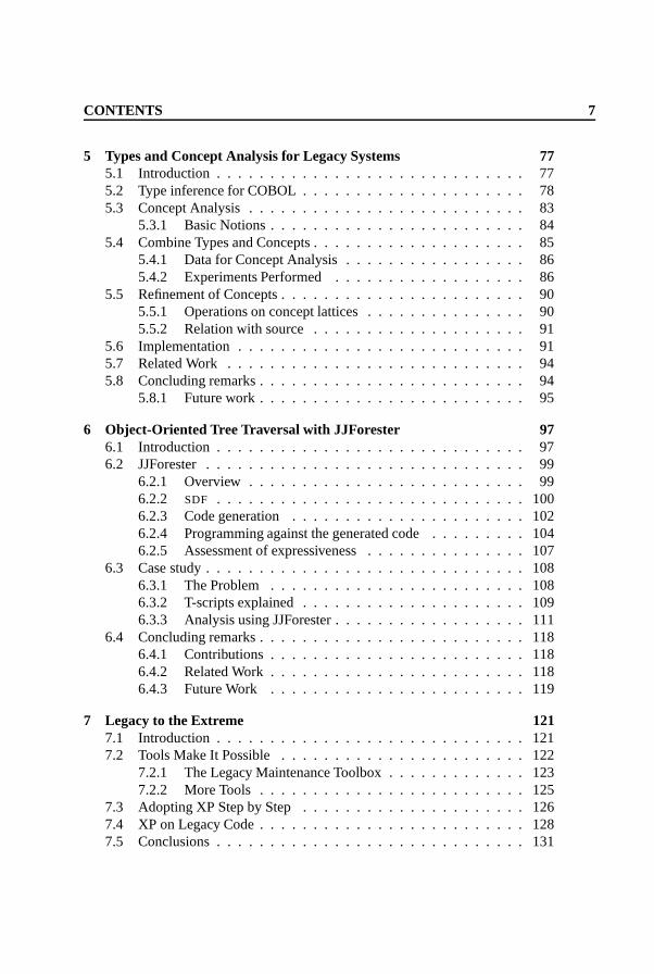
CONTENTS 7
5 Types and Concept Analysis for Legacy Systems 775.1 Introduction . . . . . . . . . . . . . . . . . . . . . . . . . . . . . 775.2 Type inference for COBOL . . . . . . . . . . . . . . . . . . . . . 785.3 Concept Analysis . . . . . . . . . . . . . . . . . . . . . . . . . . 83
5.3.1 Basic Notions . . . . . . . . . . . . . . . . . . . . . . . . 845.4 Combine Types and Concepts . . . . . . . . . . . . . . . . . . . . 85
5.4.1 Data for Concept Analysis . . . . . . . . . . . . . . . . . 865.4.2 Experiments Performed . . . . . . . . . . . . . . . . . . 86
5.5 Refinement of Concepts . . . . . . . . . . . . . . . . . . . . . . . 905.5.1 Operations on concept lattices . . . . . . . . . . . . . . . 905.5.2 Relation with source . . . . . . . . . . . . . . . . . . . . 91
5.6 Implementation . . . . . . . . . . . . . . . . . . . . . . . . . . . 915.7 Related Work . . . . . . . . . . . . . . . . . . . . . . . . . . . . 945.8 Concluding remarks . . . . . . . . . . . . . . . . . . . . . . . . . 94
5.8.1 Future work . . . . . . . . . . . . . . . . . . . . . . . . . 95
6 Object-Oriented Tree Traversal with JJForester 976.1 Introduction . . . . . . . . . . . . . . . . . . . . . . . . . . . . . 976.2 JJForester . . . . . . . . . . . . . . . . . . . . . . . . . . . . . . 99
6.2.1 Overview . . . . . . . . . . . . . . . . . . . . . . . . . . 996.2.2 SDF . . . . . . . . . . . . . . . . . . . . . . . . . . . . . 1006.2.3 Code generation . . . . . . . . . . . . . . . . . . . . . . 1026.2.4 Programming against the generated code . . . . . . . . . 1046.2.5 Assessment of expressiveness . . . . . . . . . . . . . . . 107
6.3 Case study . . . . . . . . . . . . . . . . . . . . . . . . . . . . . . 1086.3.1 The Problem . . . . . . . . . . . . . . . . . . . . . . . . 1086.3.2 T-scripts explained . . . . . . . . . . . . . . . . . . . . . 1096.3.3 Analysis using JJForester . . . . . . . . . . . . . . . . . . 111
6.4 Concluding remarks . . . . . . . . . . . . . . . . . . . . . . . . . 1186.4.1 Contributions . . . . . . . . . . . . . . . . . . . . . . . . 1186.4.2 Related Work . . . . . . . . . . . . . . . . . . . . . . . . 1186.4.3 Future Work . . . . . . . . . . . . . . . . . . . . . . . . 119
7 Legacy to the Extreme 1217.1 Introduction . . . . . . . . . . . . . . . . . . . . . . . . . . . . . 1217.2 Tools Make It Possible . . . . . . . . . . . . . . . . . . . . . . . 122
7.2.1 The Legacy Maintenance Toolbox . . . . . . . . . . . . . 1237.2.2 More Tools . . . . . . . . . . . . . . . . . . . . . . . . . 125
7.3 Adopting XP Step by Step . . . . . . . . . . . . . . . . . . . . . 1267.4 XP on Legacy Code . . . . . . . . . . . . . . . . . . . . . . . . . 1287.5 Conclusions . . . . . . . . . . . . . . . . . . . . . . . . . . . . . 131

8 CONTENTS
8 Conclusions 1338.1 Reduce Search Space . . . . . . . . . . . . . . . . . . . . . . . . 1338.2 Information for Structural Change . . . . . . . . . . . . . . . . . 1348.3 Altering the Software Engineering Process . . . . . . . . . . . . . 134
Summary 145
Samenvatting 149

Preface
The work presented in this thesis was performed over a period of four years at theCenter for Mathematics and Computer Science (CWI) in Amsterdam, The Nether-lands. Over this period, more and more interest in our group’s research was ex-pressed by various companies. A number of people in the group had been toyingwith the idea of starting a company to aid in the technology transfer of the CWI re-search for some years, and this seemed like the ideal situation to actually start thiscompany. I am very fortunate to have been part of both the research group, and thestart-up company. In fact, I moved from CWI to the Software Improvement Group(the startup) after my four years at CWI, when all I had to do to finish this thesiswas to “write the preface”.
It took me over a year to actually finish it, and the fact that I did can hardlybe attributed to me. I would like to thank the people who it can be attributed toprofoundly: Arie van Deursen was the project leader of the project I first joinedat CWI. He was my mentor, and taught me how to write research papers. Hehas become a good friend and (less important) a partner in the aforementionedcompany. Paul Klint taught me how to finish a thesis, mainly by not asking whenI was going to finish it. Apart from that, he was one of the most accessible thesisadvisors I know, and has been an inspiration. I fondly remember the seeminglyrandom state-of-the-world talks we had (and still have).
Other people at CWI that need to be applauded are Joost Visser, who knowshow to separate the important stuff from the less important stuff, thus makingyou go twice as fast on a good day. Especially our long discussions over dinner(after long discussions on where to eat) have been very educational (We need morecoasters!). Leon Moonen has been there since we started, we shared a room asassistants at the UvA. Leon prefers rooms at least 5 degrees colder than I do, so wedidn’t share rooms at CWI. We did have a lot of very productive discussions, overeven more coffee, however (Let’s go skating when I’m done). Merijn de Jongewas an instrumental part of the team who always asked whether what you weredoing couldn’t be done better. He has written a number of very elegant softwarepackages I use everyday. Furthermore, he got us home when we went sailing andthe rudder fell off.

10 CONTENTS
Dinesh was my first roommate, and the first to go. Dinesh showed me that itwas okay to have non-conventional ideas (at least for him). He has become a goodfriend, at which point he packed his stuff and moved half way across the world. Idid visit him in California, after which he moved to yet another continent. Let’ssee what happens when I visit him there. Jeroen Scheerder showed me lots of coolMac stuff, which made me buy the one I’m typing this on now. Apart from that,he produced some of the software that was needed to do the research in this thesis.Jurgen Vinju took my place as the weekly talk organizer. He manages to buy all thenice gadgets at the right time, although he should be legally barred from buyingcars. He, too, wrote some of the software I still use everyday. I hope he keepscalling me telling me he bought me a ticket to this cool show at the Paradiso (Houhet werkelijk!).
I enjoyed working at CWI and like to thank the rest of the group for providingsuch a nice environment: Mark van den Brand, Ralf Lammel, Jan Heering, PieterOlivier and Hayco de Jong, thanks!
I need to congratulate Eelco Visser on becoming a daddy, and need to thankhim for being instrumental in my pursuing a research job in the first place. Let’sdo something together, now that I have a bit more time.
Over at the Software Improvement Group, I have to thank you all! Guys, weare doing good! Marjo Wildvank has taught me more about business then I everthought I’d wanted to know. He is a master story teller, and I am starting to believethat his stories are true, too. Alex van den Bergh has rescued me on more than oneoccasion. Thank you for putting up with me, and for the great work you do, eventhough being cool is not a part-time job. Visit checkdef.com! Other SIG people:Steven Klusener, Gerard Kok, Indra Polak, Ernst Verhoeven, and more recentlyAlbertine Frielinck, thank you very much for your sense of humor, and for yournice work (and the bedrijfsuitjes).
Fortunately, I still seem to have sort of a life, which is largely due to variousfriends calling and demanding to go have a beer somewhere, or come over fordinner. You know who you are.
Rap9 is such an institution that I almost feel I don’t need to mention it. I amgrateful that I can be part of a football team with such a history, and such brilliantplayers. We will become champions, although I fear who will tattoo what where,when it happens.
My Mom and Dad were there first, and apparently will support me, no matterwhat. What can I do in return, but to install and fix their computer? The factthat they moved to just a couple of blocks from our place make my visits morefrequent and always fun, especially when dinner is involved (I still haven’t had theworteltjesspaghetti!). I also thank my little big brother for being my brother. Let’shang out more.
Johan Prins and Maria Sindram, thank you having me visit you in the US, lastlyin Charleston, S.C., where part of this thesis was written.

CONTENTS 11
Finally, the one person who actually did all the work, supported me throughoutmy time at CWI and SIG, while graduating, starting her own career, getting a newjob, taking me on beautiful holidays to Britanny and finding the time to actuallymarry me in between... Maartje, thank you for making me a better person.

12 CONTENTS

Chapter 1
Introduction
Every software system that is being used needs to be maintained. Software is onlyfinished when it is no longer in use. However, the rate of change may vary wildlyfrom system to system. The number of releases for a new internet application thatneeds to stay ahead of the competition by adding features every week may be veryhigh. It is typically low for embedded systems software, because of the high costof retrofitting for instance your television with new software.
There are three main reasons for changing software, the so-called softwaremaintenance categories [Swa76].
Corrective maintenance The first reason software needs to be changed is faultrepair (or bug fixing). No software is delivered fault free, and during thelifetime of the software some of those faults will become apparent and needto be fixed.
Perfective maintenance A second reason software needs to be changed is ofcommercial nature. When a company brings out a software product in acompetitive market, then the competition may want to change their productto stay competitive. Software may also need change to reflect the businessprocess of a particular company. The software used inside large services or-ganizations may be modeled upon the structure of the organization. If thereis a division “Regional offices” then that division usually has its own sys-tems, as has the division “Foreign offices”. Were the company to reorganize,and these two divisions to be merged into a new division “Offices”, then thishas consequences for the two software systems.
Adaptive maintenance Finally, systems may need to change for legal or techni-cal reasons. The system may need to run on different hardware or it mayneed to be upgraded to run on a different operating system. Legal changescould include the modification of currencies on which the system operates,

14 Introduction � 1
or a change in the time during which historical data is stored by the sys-tem. After the change the system will perform the same task as before, withhardly any visible change for the user.
An overview of different measurement studies presented in [Pig97] shows thaton average about 80% of maintenance cost is in either perfective or adaptive main-tenance (or non-corrective maintenance) and about 20% in corrective maintenance.
1.1 Maintaining Legacy Systems
When, for whatever reason, an existing system needs to be modified, it will in-variably be seen as a legacy system (at least in part). That is, the system is thelegacy of the people who have created it, or have modified it previously. In theideal situation the original development team will stay on as maintainers of thesystem throughout its lifetime. This way, everyone who was ever involved in thedesign and building of the system is available to change it. Unfortunately, this isnever the case. Traditional software engineering distinguishes strongly betweendevelopers or creators of a system, and maintainers of the same system. This fol-lows the traditional manufacturing model, where a product, for instance a car, isdeveloped and built by a team of people. Once the car is finished and delivered,the maintenance of the car will be performed by a different team.
The process of keeping a software system in tune with the needs of its users isreferred to as software evolution. In order to be able to evolve a system, its main-tainers need to know, in some detail, the inner workings of that system. Becausethey did not design nor develop the system, this knowledge does not come to themnaturally. In an ideal case, there is ample knowledge about the system availableoutside of it in the form of design documents, both functional and technical, andactual technical documentation of the source code of the system. What’s more,the original designers and developers of the system may be available to answerquestions. Unfortunately, for the original development team there is no need toproduce accurate, factual, and concise design documents, because they can buildthe system without them. Moreover, in a traditional software engineering environ-ment, the designers of a system will produce a design document that cannot beimplemented as is. All sorts of details in a design will be deemed “implementa-tion details”, and will be left to the developers to sort out. In order to sort out theimplementation details, the developers may need to (and will) stretch the design alittle to accommodate for their best solution. This is not a problem as long as theintention of the original design was clear to both designer and developer, becausethen the chosen solution will be a common one. Unfortunately, the slight changein the design is only documented in the head of the developer who made it. Dur-ing the development of a non-trivial system there are hundreds, if not thousandsof such implementation details to decide about, and each one may warrant their

1.1 � Maintaining Legacy Systems 15
own slight design change. These can add up to quite major changes which are notdocumented anywhere.
Software developers get away with this (as opposed to car developers) becausethere is no intrinsic need for these documents. Software developers in general builda single software system, which, once it is finished, can be copied an infinite num-ber of times for negligible cost. This single copy is built by a single developmentteam. This is as true for both mass distributed software as it is for single-purposecustom built software. Building a single car in the contemporary car market cannever be cost effective. The volume production of cars is what keeps a car manu-facturer going, so the need for documents that trace the exact steps to create a car isparamount. Not only do all cars need to be built from scratch, there is not a singledevelopment team. A single car model may be built on several sites distributed allover the world, and at each site they may be built by several teams.
1.1.1 Software Engineering for Maintenance
The previous paragraph should have started with the sentence “software developersget away with this temporarily”, because in most of the cases software developersdo not get away with it over time. Unlike cars, the finished software productcan be changed to become a slightly changed, or even radically different softwareproduct. As described above, these changes are almost impossible to make withoutan understanding of the inner workings of the system, and may still be very hardwith such an understanding.
A number of methods have been proposed and applied in the past to allow forpeople new to the system to understand it in the amount of detail they need to dotheir work. These people have been called “Software Immigrants” in the literature[SH98].
The source code of a software system can be seen as a document that describesexactly what the system does, by definition. Unfortunately, this is done in suchenormous detail that it is hard for any individual to keep an overview of the wholesystem. In order to maintain an overview, and help introduce “software immi-grants” to the system, some other, less detailed, source of information is needed.The methods described below all propose a different way to create, and maintainthat other source of information about the system.
Traditional Software Engineering The traditional “waterfall” software engi-neering model starts from the premonition that software is only developed once,and that, once it is developed, it will enter into a maintenance state. When thesoftware enters from the development stage into the maintenance stage, a numberof documents should be delivered as well. Different methodologies here requiredifferent documents, but in general there should be a functional design document,which describes the overall functionality of the system, there should be a technical

16 Introduction � 1
design document, which describes the overall technical layout of the system, thereshould be in-depth technical documentation on a per-module, or per-program level,and the source code itself could be required to adhere to certain coding standardsand contain information about the code.
Evidence suggests that the average software system designed and built follow-ing this method spends about 70% of it’s time and effort and cost in the mainte-nance stage[Pig97], and in that stage the system may be changed quite drastically.However, after 5 years of maintenance, only the documents from the date of de-livery are available, which tend to be horribly outdated, particularly the technicaldocumentation.
More cyclical methodologies have been developed, to iterate over the designand development phase. Errors discovered during the development phase can bereset in the following design refinement phase. Unfortunately, these methodolo-gies, for example Boehm’s Spiral Model [Boe88], also end with the implementa-tion phase, and do not consider themselves with maintenance at all.
What is apparent in these models is that a strict dichotomy exists between theactual software system that is running on a computer (the combined source code)and the documents available about the system. That is, the actual software systemmay or may not do what is in the documentation, and there is no way to guaranteethat the two are in any way related.
Literate Programming Literate programming [Knu84] has been proposed as asolution for this problem: literate programming requires the developer to have asingle document containing both the program text, as well as the documentationthat describes the program text. In fact, literate programming in its purest form re-quires the developer to produce a book describing the problem the software systemis going to solve, how this problem can be broken down into smaller problems, andhow all these small problems can be solved individually by a very small piece ofsoftware, which is so small that it can be printed in the book and understood in-stantaneously. The advantage of having both documentation and code in the samedocument is that the engineer who has to modify the code has the documentationright there on his screen. When he needs to modify the system, he should first de-cide where the error is: Is it in the narrative of the book? Then he needs to fix thenarrative, and then the source code. If the narrative is correct, then there somehowis a fault in the code, and he should fix it. This method requires a lot of disci-pline from developers to fix the narrative before the code. Even though the two arein the same document, the relation between the two is purely circumstantial: thenarrative may tell a completely different story from the code.
Executable Specifications Another proposed solution comes in the form of ex-ecutable specifications. Here the design of a system is laid down in a formal sys-tem specification document. The actual implementation of the system is then de-

1.2 � Changing Legacy Systems 17
rived from that specification automatically. Because the specification language is,in fact, a (very) high-level programming language, the design, or specification,cannot skip over the already mentioned implementation details. This means thatformal specifications of non-trivial problems may contain much more detail thanwould be written down in a natural language design document. To introduce a newengineer to the system, natural language documents are needed, and the advan-tage of formal specifications over “regular” programming languages with respectto understandability and maintainability are lost.
Domain Specific Languages Domain Specific Languages are usually extremelyhigh level languages that borrow parts of their syntax from the vocabulary of acertain problem domain. Having “programmers” who are well-versed in this par-ticular problem domain solves the problem of having software immigrants. Beingdomain experts, these people are already familiar with the same vocabulary thatthe domain specific language is built from. Having, or creating a domain specificlanguage is, by definition, only feasible in a situation where the problem domainis extremely well defined. Furthermore, having a domain specific language canonly be profitable if a number of systems will be developed in the same problemdomain, to warrant the initial investment in the development of the domain specificlanguage itself [DK98].
Extreme Programming The most extreme solution is provided by the aptlynamed Extreme Programming (XP) methodology. XP does not distinguish at allbetween design, testing, development, or maintenance stages. Instead, a team ofengineers produces a tiny, but working system in a couple of weeks, and keepsmodifying and extending that system into the system that is actually requested bythe customer. There are no design documents, or at least no persistent design doc-uments; the design of the system is the source code itself. Because all engineersthat are maintaining the system have helped develop and design it, their knowledgeabout the system comes naturally. Writing documentation or commenting code isactually discouraged, because it will be outdated the moment someone changesthe code. Understandability should be achieved by creating readable code. Be-cause all code is written in rotating pairs, there is no one engineer with exclusiveknowledge of (part of) the system.
1.2 Changing Legacy Systems
Even though there is a lack of documentation and a lack of people with insight intothe system, the legacy system still needs to be changed. The changes that can bemade to a legacy system can fall into one of two categories. Both types of changeshave their particular reasons, and both require a different type of knowledge about

18 Introduction � 1
the system to be available for the engineer. Of course the difference between thetwo types of change is not always clear; the two categories can be seen as the twoends of a change spectrum.
1.2.1 Minor Change
Minor changes in a software system are usually operational in nature: a systemterminates on unexpected or illegal input, or it produces the wrong results for aparticular input. An engineer is called in to repair the program as soon as possible,to get it up and running again. Large batch processes on mainframe computerstypically run at night, with a single engineer standing by to fix things when theygo wrong. It is impossible for this one engineer to know very much about allthe systems that may be running at any given night. When the system breaksdown, the engineer needs access to information about the system very fast, and willnot be bothered by the amount of detail the information contains. The first goalof the information available should be to decrease the search space in which theproblem can be found. If at a given night 25 systems are running, and each systemconsists of 200 modules, then having information available that within minutespinpoints the error in one of the 5000 modules is invaluable. Further informationthat narrows the error down even further to a particular section of a module maybe useful, but if the information takes half an hour to retrieve then its usefulness israther limited, because an engineer can probably read the whole module in abouthalf an hour.
Minor changes occur where an otherwise working system breaks down. Ob-viously, this is not a definition but rather a vague description: If a system breaksdown on January 1st, 2002, because it cannot process the Euro currency, hardlyany software engineer will tell you that fixing this problem would involve only aminor change.
1.2.2 Structural Change
Fixing an error such as being incapable of processing the Euro may not lead tostructural change per se: The engineer could just change every occurrence of theguilder or the mark into an occurrence of the Euro. Although this may affect alarge part of the system (and typically will, in legacy systems) the actual structureof the program may not have to be changed. If however the engineer decides to fixthe problem once and for all, then he may decide to put all occurrences of money ina single part of the system, and have all other parts of the system reference this partif necessary. Then, at the introduction of the global unified currency he will onlyhave to change his one money part, and the rest of the system will be unaffected,thus the problem will be reduced to a minor change.
The process of finding and relocating all references to (in this case) parts of thesystem that relate to the processing of a particular currency is deemed structural

1.3 � Research Questions 19
change. The information needed to perform such a change is much more detailedand harder to obtain than the information needed for minor changes. For example,in the previous section, it didn’t matter very much if the information available onlylead to the first occurrence of the problem: the aim of the engineer was to get thesystem running again. The second occurrence of the same problem may not appearthat night, or only hours later: in the mean time, valuable computations might havebeen performed that may not have been performed if the engineer spent his timelooking for other occurrences of the same problem.
When performing a structural change, the engineer would definitely have tofind any and all references to currencies: if he would miss a single database re-trieval operation, then guilder amounts may be subtracted from euro amounts orvice versa with all commercial and possibly legal consequences that may have.
When performing structural changes, time is usually less of a constraint thanwith minor changes. Accuracy is instead of extreme importance. Especially con-sidering that the above example is one of the less complex forms of structuralchange.
More complex structural changes would be to change a system consisting ofan online and a batch subsystem (for instance a checking account managementsystem) into a client/server system. Here all the parts of the system that have to dowith batch processing (typically the transferral of money from one account to theother) and the parts that have to do with online querying (balance retrieval, addingand removal of transfers, etcetera) are separated completely. At a certain momenteach day (say 7 PM) the system moves from online mode to batch mode. At thattime, balances can no longer be requested, and transfers can no longer be added orremoved. Changing such a software system to (for instance) a client/server systemthat does not have harsh restrictions on which action can be performed at whattime is a very complex structural change.
A final example of complex structural change of a software system is a changeof implementation language. Legacy systems are typically implemented in lan-guages that lack certain features that make software written in modern languagesbetter understandable and maintainable. A form of modernization can be to re-implement the system in a different language.
1.3 Research Questions
This thesis does not deal with producing better software. It does not try to helppeople deliver fault-free software, or software that does not have to be changed.Instead it tries to help in making existing systems more flexible by supporting theengineers who need to change them with the appropriate technology. The concreteresearch questions that this thesis tries to answer are:
� How can we reduce the search space when searching for a particular artifact

20 Introduction � 1
in a legacy software system?
� How can we obtain sufficiently detailed information about a legacy softwaresystem to perform a structural change (semi-)automatically?
� How can we alter the software engineering process such that we no longerproduce legacy systems?
Reduce Search Space The process of relating a certain externally perceivablefeature of a software system to an internal artifact (the traceability of a feature) isone of the most frequently occurring activities in software maintenance. When asystem contains millions of lines of code, automatically reducing the search spacefor a particular artifact can save hours if not days per search. Ideally, the searchspace is decreased to exactly those parts of the system that do something with theexternally perceived feature.
Information for Structural Change Getting detailed information out of a legacysystem per se is not necessarily hard. The problem is that the amount of detailedinformation may be (and usually is) so enormous, that it is useless unless pro-cessed (semi-)automatically. That is, the raw data extracted from a legacy systemshould be processed somehow to diminish in volume, but to increase in usefulness.An example could be that retrieving all database operations from a legacy systemreturns an enormous amount of data. Cross-referencing all the operations with thedatabase schema, and filtering out only the operations on numbers gives back lessdata. If it would be possible somehow to filter the operation out even further to getonly operations on numbers that represent a certain currency, then this would bethe exact data needed for a currency conversion project.
Altering the Software Engineering Process As was described in Section 1.1.1traditional software engineering hardly concerns itself with maintenance explicitly.If it does, it is seen as a completely separate activity from software development,to be performed by different people than the original developers. There are nopractical steps in the software engineering process to prevent a system from be-coming a legacy system. In fact, some people state that “programming leads tolegacy systems” [Vis97b]. From that thesis follows that one way to prevent yoursystem from becoming a legacy system is to never program it in the first place.However, there may be a slightly less drastic modification that can be made in thesoftware engineering process to get rid of legacy systems.

1.4 � Reader’s Roadmap 21
1.4 Reader’s Roadmap
As stated earlier, there is a sliding scale from performing a minor change on asoftware system to performing a structural change. This thesis concerns itself withthese two types of changes and the information required to perform them.
The first chapters, “Rapid System Understanding” (Chapter 2) and “BuildingDocumentation Generators” (Chapter 3) deal with retrieving and presenting infor-mation from a legacy software system in such a way that a maintenance engineercan retrieve a particular artifact in the system with maximum speed.
The next chapter, “Identifying Objects with Cluster and Concept Analysis”(Chapter 4) examines what data from a legacy system is required to derive a so-called object oriented design from that system. In an object-oriented design, pro-cedures and the data they operate on are logically grouped. Chapter 4 examinestwo methods of automatically performing such a grouping and examines the prosand contras of each method.
One of the methods examined in Chapter 4 is used in the next chapter (“Typesand Concept Analysis for Legacy Systems”, Chapter 5) to group data in a differentway. Here, data is grouped based on the way it is used to calculate new data.This way, we can get answers to questions like: what pieces of data in this systemrepresent a monetary value, or what pieces of data represent a date, or an accountnumber.
Where Chapters 4 and 5 mainly deal with the presentation and filtering ofalready extracted data from a system, Chapter 6 (“Object-Oriented Tree Traversalwith JJForester”) shows a technique for retrieving the actual detailed elementsfrom the source code in an elegant and easy way.
Chapter 7 sketches a possible scenario of what could happen when a team ofsoftware maintainers tries to adopt the software engineering methodology calledExtreme Programming.
The final chapter (Chapter 8) draws conclusions and examines how the re-search questions posed here have been answered.

22 Introduction � 1
Sources of the Chapters
Chapter 2, “Rapid System Understanding”, was co-authored by Arie van Deursen.It was published earlier as:
A. van Deursen and T. Kuipers. Rapid system understanding: TwoCOBOL case studies. In S. Tilley and G. Visaggio, editors, Sixth In-ternational Workshop on Program Comprehension; IWPC’98, pages90–98. IEEE Computer Society, 1998.
Chapter 3, “Building Documentation Generators”, was co-authored by Arie vanDeursen. It was published earlier as:
A. van Deursen and T. Kuipers. Building documentation generators.In International Conference on Software Maintenance, ICSM’99, pages40–49. IEEE Computer Society, 1999.
Chapter 4, “Identifying Objects with Cluster and Concept Analysis”, was co-authored by Arie van Deursen. It was published earlier as:
A. van Deursen and T. Kuipers. Identifying objects using clusterand concept analysis. In 21st International Conference on SoftwareEngineering, ICSE-99, pages 246–255. ACM, 1999.
Chapter 5, “Types and Concept Analysis for Legacy Systems”, was co-authoredby Leon Moonen. It was published earlier as:
T. Kuipers and L. Moonen. Types and concept analysis for legacy sys-tems. In Proceedings of the International Workshop on ProgrammingComprehension (IWPC 2000). IEEE Computer Society, June 2000.
Chapter 6, “Object-Oriented Tree Traversal with JJForester”, was co-authored byJoost Visser. It was published earlier as:
T. Kuipers and J. Visser. Object-oriented Tree Traversal with JJ-Forester. In Proceedings of the First Workshop on Language De-scriptions, Tools and Applications 2001 (LDTA’01). Electronic Notesin Theoretical Computer Science 44(2). Elsevier Science Publishers,2001.
Chapter 7 “Legacy to the Extreme”, was co-authored by published earlier in “Ex-treme Programming Examined”, published by Arie van Deursen and Leon Moo-nen. It was published earlier as:
A. van Deursen, T. Kuipers, and L. Moonen. Legacy to the extreme.In M. Marchesi and G. Succi, editors, eXtreme Programming Exam-ined. Addison-Wesley, Reading, Massachusetts, May 2001.

Chapter 2
Rapid System Understanding
This chapter describes the rapid extraction of facts from a legacysoftware system. When an engineer tries to relate a feature of a soft-ware system to an artifact inside that same system, he would like toknow what parts of the system to look for, and what parts of the systemto ignore. Rapid System Understanding investigates the techniquesnecessary to achieve that goal.1
2.1 Introduction
Rapid system understanding is the process of acquiring understanding of a legacysoftware system in a short period of time. Typical tasks that require rapid systemunderstanding are:
� Assessing the costs involved in carrying out a European Single Currency oryear 2000 conversion;
� Estimating the maintainability of a system, for example when deciding aboutaccepting or issuing a maintenance outsourcing contract;
� Investigating the costs and benefits of migrating a system to an object-orientedlanguage, in order to increase its flexibility and maintainability;
� Determining whether legacy code contains potentially reusable code or func-tionality.
1This chapter was published earlier as: A. van Deursen and T. Kuipers. Rapid system understand-ing: Two COBOL case studies. In S. Tilley and G. Visaggio, editors, Sixth International Workshop onProgram Comprehension; IWPC’98, pages 90–98. IEEE Computer Society, 1998.

24 Rapid System Understanding � 2
Lexical Analysis
Relational DatabaseSyntax Analysis
Dataflow Analysis
Report Generation
Cross ReferencingMetrics, Style,Comments, ...
Cluster AnalysisGroups of Data/Functionality, ...
Visualization Call GraphPerform Graph
Database Usage, ...
Program Sources
Figure 2.1: Architecture of tool set used
Performing these tasks should be cheap: one expects a cost estimate of, say,a year 2000 conversion to be significantly less expensive than carrying out thatconversion. This is where rapid system understanding differs from more tradi-tional system understanding. Accepting a less detailed understanding and slightlyinaccurate results, a first assessment can be made quickly.
We assume that the engineer who needs to acquire understanding of a legacysystem has negligible previous experience with it. He may be unfamiliar withsome of the languages or dialects used in the legacy code. The systems involvedare typically large, multi language, over 10 years old, and written by differentprogrammers.
In this paper, we take two 100 KLOC COBOL systems from the banking areaas our starting point. We address a number of related questions: What tools ortechniques can be used in rapid system understanding? How well do they work forour case studies? What information can be extracted from legacy source code, andhow should this information be interpreted?
The paper is organized as follows. In Section 2.2 we explain what tools andtechniques can be used, and how these cooperate. In Section 2.3 we list the char-acteristics of the two COBOL systems under study. In Section 2.4 we describethe kind of information we extracted from the legacy code, while in Section 2.5we discuss the possible interpretation of this data. In Sections 2.6, 2.7 and 2.8 wesummarize related work, conclusions and future work.
2.2 Tool Architecture
Rapid system understanding implies summarizing of data. In order to understanda large legacy system, it is necessary to quickly find the “essence” of such a sys-tem. What constitutes this essence largely depends on the reasons for trying tounderstand the system.
Our approach is to analyze the code using generic tools that have no a-prioriknowledge of the system. The results of this analysis are then fed into a central

2.3 � Cases Investigated 25
repository. In turn, this repository can then be queried, printed, visualized, etc.The querying of the repository leads to a certain degree of understanding of thesystem. We can exploit this understanding by creating analysis techniques thatdo contain (a degree of) specific knowledge of the system. This will lead to datain the repository that is more suited for our specific goals. Again, this data canbe visualized, queried, etc., to gain a greater understanding of the system. Thisprocess is repeated until the engineer who tries to understand the system has gainedsufficient knowledge of it.
The general architecture of our tool set consists of three main parts, as shownin Figure 2.1. The first part is the code analysis part, the second the repository, andthe third the tools that manipulate and present data from the repository.
For the code analysis part lexical, syntactic or other forms of analysis can beused. The figure distinguishes lexical, syntactic [dBSV97a], and data flow analy-sis. For the purpose of rapid system understanding, it will generally suffice to uselexical analysis. It can be performed faster than syntactic analysis, and is muchmore flexible [MN96].
To extract a number of relations from COBOL legacy systems, we have de-veloped a simple Perl [WS91] script called ������������� . It knows about COBOL’scomment conventions, keywords, sectioning, etc. It can be used to search thesources for certain regular expressions, and to fill tables with various relations, forexample pertaining to the usage of databases, call structure, variable usage, etc.The data extracted for COBOL is discussed in full detail in Section 2.4.
We store the analysis results as comma-separated-value (CSV) files. Such filescan be easily queried and manipulated by Unix tools such as � � [AKW88] and ����� , and can be read by arbitrary relational database packages enabling us to useSQL for querying the data extracted from the sources. These tools can also beused to generate reports, for example on the usage frequency of certain variables,or containing the fan-in/fan-out metric of sections of code.
Many relations stored in the repository are graphs. We use the graph drawingpackage � ��� [GKNV93] for visualizing these relations.
2.3 Cases Investigated
Central in our research are two COBOL systems from the banking area, which inthis paper we will refer to as Mortgage and Share. Mortgage is a relation admin-istration subsystem of a mortgage system. Share is the order-input (OI) subsystemof the ABN-AMRO stockbroking system. The respective owners of these systemsare in general satisfied with their functionality, but less satisfied with their plat-form dependency. They are interested in extracting the essential functionality ofthese systems, in order to incorporate it into a more flexible, object-oriented, ar-chitecture. Thus, questions of interest include: Do these systems contain reusable

26 Rapid System Understanding � 2
Mortgage no LOC avg
copybooks 1103 49385 44programs 184 58595 318total 1288 107980 83
Share no LOC avg
copybooks 391 16728 42programs 87 104507 1201total 479 121235 253
Figure 2.2: System inventory.
code? What fraction of the code is platform specific? Which data fields representbusiness entities? Which procedures or statements describe business rules?
The sizes of the two systems are summarized in Figure 2.2. Mortgage is aCOBOL/CICS2 application using VSAM3 files. It is partly on-line (interactive),partly batch-oriented, and in fact only a subsystem of a larger (1 MLOC) system.Share is an IMS4 application which uses both DL/I5 (for accessing an IMS hier-archical database) and SQL (for accessing DB2 databases).
For Mortgage, we had system-specific documentation available, explainingthe architecture and the main functionality of the programs. The documentationmarked several programs as “obsolete”: some of these were included in the versiondistributed to us, however. For Share, no specific documentation was available:we only had a general “style guide” explaining, for example, the naming conven-tions to be used for all software developed at the owner’s site.
2.4 Collected Data
In this section, we discuss how we used the tool set of Section 2.2 to extract datafrom the Mortgage and Share sources, and how we displayed this data in a com-prehensible manner. The results of the analysis will be discussed in Section 2.5.
2.4.1 System inventory
The system inventory table summarizes available files, sizes, types (copybook,program), and languages used (COBOL, CICS, SQL, DL/I, ...). The copybook ta-ble indicates how copybooks are included by programs (a simple lexical search forthe arguments of the
�������command). If appropriate, for certain files (copybooks)
2CICS is Customer Information Control System, a user interface and communications layer3VSAM is Virtual Storage Access Method, an access method for records4IMS is Information Management System, a database and data communication system5DL/I is Data Language 1, a database management language

2.4 � Collected Data 27
it can be detected that they were generated, for example if they contain certaintypes of comment or keywords. The system inventory derived for Mortgage andShare was used to obtain Figure 2.2.
2.4.2 Program call graph
The call relation is a first step in understanding the dependencies between theprograms in Mortgage and Share. Deriving the call graph for COBOL programs(see Figure 2.3 for the batch call graph of Mortgage) is not entirely trivial. Firstof all, the argument of a CALL statement can be a variable holding a string value,i.e., it can be dynamically computed. The most desirable solution to this problemis to have some form of constant propagation. In our case, for Mortgage it wassufficient to search for the values of certain variables or, in Share, for stringsmatching a certain lexical pattern.
In Share, we encountered further complications. Rather than a regular CALLstatement, each call is in fact a call to some assembler utility. One of the argumentsis a string encoding the name of the program to be called, as well as the way inwhich that program is to be loaded. The assembler routine subsequently takescare of loading the most recent version of this program. Once we understood thismechanism, it was relatively easy to derive the call graph using lexical patternmatching.
In Mortgage, the use of CICS provides further possibilities of calling pro-grams. The first is the CICS LINK statement, which is similar to a CALL state-ment. The second is the CICS XCTL statement. This takes care of invoking aprogram just before or after an end-user has filled in a screen as presented in anon-line session. In Mortgage, the XCTL calls could be extracted by tracing thevalue of a specific variable.
Observe that these special call conventions imply that commercial reengineer-ing tools should be sufficiently flexible to allow such organization-specific ex-tensions. We have looked at two of the most advanced COBOL reengineeringtools currenly available, Reasoning/COBOL [MNB
�
94] and MicroFocus/Revolve[Mic96]. Both support call graph extraction from abstract syntax trees, but neitheris able to produce the on-line call graph of Mortgage or the batch call graph ofShare. They can be adapted to produce these graphs, but that will be more timeconsuming than specifying a simple lexical search, making the latter option moreattractive in a rapid system understanding setting.
2.4.3 Database usage
A viable starting point for locating data entities of interest is the data that thesystem reads from or stores in persistent databases. In Mortgage, VSAM filesare used, and both COBOL as well as CICS constructs to access them. In Share,

28 Rapid System Understanding � 2
RA
09
AA
04A
A05
RA
10
AA
02
RA
12
RA
20
HA
03
RA
22
RA
36R
A41
RA
24
RA
40R
A25
RA
26R
A27
RA
31
HA
02R
A37
RA
38R
A39
RA
42R
A80
RA
81
RA
83
RA
89R
A90
Figure 2.3: CALL graph for the batch part of Mortgage.

2.4 � Collected Data 29
VSAM, hierarchical IMS and relational DB2 tables are used, and COBOL I/Ostatements, SQL and DL/I to access them.
In an SQL system, a datamodel listing all tables with their field names andtypes is explicitly available. The ������������� tool can be used to extract this modelfrom the source. In a non-SQL application such as Mortgage, this datamodel isnot available. What can be derived, though, is the COBOL record definition usedwhen writing to or reading from files.
Share uses 36 different tables, with in all 146 different field names. The num-ber of fields per table varies from 1 to 40 – suggesting that many tables sharecertain fields. To make this visible we generated a 60-page LATEX document. Foreach table we have one section listing the fields and their types, as well as the pro-grams in which the table was declared. We then used � � ����� � ��� to generate anindex, indicating at what pages the tables, fields, types, and programs were used.
The CRUD — create, read, update, delete — matrix indicates how databasesare manipulated by programs. As viewing a CRUD matrix of a large system iscumbersome, we use the graphical representation of Figure 2.4. The left-handcolumn contains records read, the right-hand one records written, and the middlecolumn lists the programs involved. An arrow from a record to a program indicatesa read, and an arrow from a program to a record indicates a write.
2.4.4 Field usage
The database usage and datamodel provide a rough overview of the database op-erations per program. In many cases, it is useful to look at the table field level aswell.
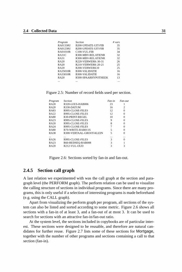
In order to expose shared use of database fields, we collect all occurrences ofdatabase field identifiers per section per program. From this table, we derive a listas shown in Figure 2.5. In Mortgage essentially 35 datafields are contained inone large table. Figure 2.5 shows how many of these datafields are used in eachsection. Of particular interest are those sections dealing with a small number (lessthan, say, 10) of data fields only.
We extracted the field usage relation using lexical analysis only. From thedatabase declarations we extracted the field names. We then matched on sectiondeclarations to find section boundaries, and identified a field usage if one of thelines in a section contains a field name as substring. Clearly, this is an approxi-mative method, relying on systematic naming conventions: the more accurate waywould be to parse the source and do dataflow analysis to follow field usage throughthe code. For the two cases studied, though, the results obtained by lexical analysiswere sufficiently accurate, at least for rapid system understanding purposes.

30 Rapid System Understanding � 2
RE
AD
PRO
GR
AM
WR
ITE
HA
R00
3
RA
0501
0RR
A32
010R
HA
R00
6
RA
0123
0UR
A33
010R
HA
R00
6R
AR
001
RA
R00
2
RA
R00
1
RA
0101
0RR
A01
330U
RA
0141
0UR
A10
CR
A31
CR
A35
030U
RA
R00
4R
AR
009
RA
R01
3
RA
R00
2R
AR
004
RA
09C
RA
R00
5R
AR
007
RA
0301
0R
RA
R00
9R
AR
011
RA
8201
0RR
A82
020R
RA
89C
RA
90C
RA
R01
2R
AR
013
HA
R00
3R
AR
005
RA
R00
7R
AR
011
RA
R01
2
RA
0302
0UR
A12
C
Figure 2.4: Graphical representation of the CRUD matrix of Mortgage.
2.4 � Collected Data 31
Program Section # varsRA01330U B200-UPDATE-UIT-FIB 35RA01230U B200-UPDATE-UIT-FIB 35RA01010R C100-VUL-FIB 34RA31C R300-MBV-RELATIENR 32RA31 R300-MBV-RELATIENR 32RA20 R220-VERWERK-30-31 26RA20 R210-VERWERK-20-21 25RA20 R200-VERWERK10 25RA35010R B300-VALIDATIE 16RA33010R B300-VALIDATIE 16RA20 R500-SPAARHYPOTHEEK 13... ... ...
Figure 2.5: Number of record fields used per section.
Program Section Fan-in Fan-outRA20 R320-LEES-HAB006 23 1RA20 R330-DATUM 16 2RA83 R995-CLOSE-FILES 12 0RA22 R995-CLOSE-FILES 12 0RA80 R30-PRINT-REGEL 10 0RA23 R995-CLOSE-FILES 9 0RA20 R995-CLOSE-FILES 8 0RA24 R995-CLOSE-FILES 7 0RA80 R70-WRITE-RAB011S 5 0RA38 R300-VERTAAL-GROOT-KLEIN 5 0... ... ... ...RA26 R995-CLOSE-FILES 3 0RA23 R60-REDSEQ-RAB008 3 1RA20 R212-VUL-OUD 3 3
Figure 2.6: Sections sorted by fan-in and fan-out.
2.4.5 Section call graph
A last relation we experimented with was the call graph at the section and para-graph level (the PERFORM graph). The perform relation can be used to visualizethe calling structure of sections in individual programs. Since there are many pro-grams, this is only useful if a selection of interesting programs is made beforehand(e.g. using the CALL graph).
Apart from visualizing the perform graph per program, all sections of the sys-tem can also be listed and sorted according to some metric. Figure 2.6 shows allsections with a fan-in of at least 3, and a fan-out of at most 3. It can be used tosearch for sections with an attractive fan-in/fan-out ratio.
At the system level, the sections included in copybooks are of particular inter-est. These sections were designed to be reusable, and therefore are natural can-didates for further reuse. Figure 2.7 lists some of these sections for Mortgage,together with the number of other programs and sections containing a call to thatsection (fan-in).

32 Rapid System Understanding � 2
Section Performed Sections ProgramsY800-PRINT 145 17 12Y998-HANDLE-ERROR 92 92 92Y010-40-AIB 89 89 89Y010-00-AIB 81 81 81Y502-MASKER 80 25 25Y020-00-FIB 79 79 79Y020-40-FIB 66 66 66... ... ... ...Z610-82-RAB011 7 5 4Z610-80-RAB011 7 6 5Y675-STD-STRAAT 7 4 2Y625-ELF-PROEF 7 6 6Y415-INFO-SCHONEN-NIT 7 3 3Z610-03-RAB011 6 4 4Y750-STD-NAAM 6 5 3
Figure 2.7: Sections performed by different sections and programs.
2.4.6 Further experiments
While finding out how to extract the various relations from the sources, we alsoused ������������� as an enhanced COBOL lexer. The � ����������� script contains severalfunctions to ignore COBOL comment columns and lines, to split lines into strings,numbers, identifiers, keywords, and other tokens, to search for arguments of key-words, to expand copybooks, to record information encountered in earlier lines,and to store results into tables. These functions were fruitfully used to acquire anunderstanding of conventions used, relevant data, etc.
2.5 Interpreting Analysis Results
In this section, we discuss how the graphs and reports derived in the previoussection helped us to actually understand the two COBOL systems under study.
2.5.1 Understanding copybooks
Rapid system understanding is a mixture between looking at global system in-formation like the call graph and looking in more detail at a specific program inorder to obtain a feeling of its particularities. One of the aims during rapid systemunderstanding is to reduce the number of programs that need to be studied in de-tail. Having the copybook relation explicitly available will help to avoid lookingat copybooks that are in fact never included.
For Share, 136 of the 391 (35%) copybooks were not used; for Mortgage 673of the 1103 (61%) were not used. These large numbers can partly be explainedas Mortgage is part of a larger system: for safety, all copybooks were included.Likewise, Share relies on general utilities used at the owner’s site; to be safe many

2.5 � Interpreting Analysis Results 33
of these were included. We have not yet looked at other forms of dead code, suchas sections or programs never called. To detect the latter, one should also have allJCL6 scripts available, which we did not have for our case studies.
Another use of the copybook relation is to identify patterns in the copybookinclusions. It turned out, for example, that the batch and the on-line part of Mort-gage use two almost disjoint sets of copybooks.
2.5.2 Call graph and reusability
The batch call graph for a part of Mortgage is shown in Figure 2.3. This graphshows particularly well that we can identify:
� Programs with a high fan-out. From inspection we know that these are typ-ically “control” modules. They invoke a number of other programs in theappropriate order. In Figure 2.3, they are mostly grouped in the left-handcolumn.
� Programs with a very high fan-in, i.e., called by most other programs. Thesetypically deal with technical issues, such as error handling. From inspectionit is clear that they are tightly connected to legacy architecture, and are notlikely to contain reusable code. In Figure 2.3, they are grouped in the right-hand column.
� Programs with a fan-in higher than their fan-out, yet below a certain thresh-old. These programs can be expected to contain code that is reusable bydifferent programs. In Figure 2.3, they are mostly in the middle column.These programs form the starting point when searching for candidate meth-ods when trying to extract an object-oriented redesign from legacy code.
For the batch part of Mortgage, this categorization worked remarkably well.The call graph based on CICS LINK commands (not shown) contains the re-
maining calls. Due to the presence of error handling modules, this call graph wasdifficult to understand. Removing all modules with fan-in higher than a certainthreshold (say 10), we obtained a comprehensible layout.
For Mortgage, this analysis of the call graph led to the identification of 20potentially reusable programs that performed a well-defined, relatively small task.
For Share, only 50% of the programs were contained in the call graph; theremaining programs are called by JCL scripts, which we did not have available.Therefore, for Share further ways of identifying reusable code will be required.
At a finer granularity, analysis of the PERFORM graph will be an option. Inprinciple, the same categorization in control, technical, and potentially reusablecode can be made. The derived table of Figure 2.6 can help to find sections of an
6JCL is Job Control Language, a shell-like system for MVS.

34 Rapid System Understanding � 2
acceptable fan-in. Clearly, this list is rather large, and not all sections will be rele-vant: we decide to inspect the code of a section based on its name. For example, wecould probably ignore CLOSE-FILES, but should take a look at VERTAAL-GROOT-KLEIN7, especially since this section occurs in three different programs.
Analysis of the sections included in copybooks as shown in Figure 2.7 willproceed along the same lines: based on the number of perform statements andthe name of the section (for example, STD-STRAAT, indicating processing of aSTRAAT, i.e., street), we will inspect code of interest. Surprisingly, Share doesnot use any sections defined in copybooks.
2.5.3 Understanding data usage
The tools provide three ways to understand the data usage. The first is the indexof tables, attributes, types and programs derived from SQL data definitions. Thisindex can be used to detect, for example, sets of attributes that occur in severaldifferent tables and hence may be (foreign) keys.
The second aid is the CRUD matrix, which shows which programs read orwrite certain tables. We used Figure 2.4, which shows the database usage forMortgage, to identify databases that are only read from (for example the “zip-code book”, shown in the top-left corner of Figure 2.4) or only written to (logging,shown in in the top-right corner), databases used by many programs, or programsusing many databases. We also used this figure to identify those databases that areused by most other programs. For Mortgage, there are only three such databases.The tools indicate which (level 01 COBOL) record definitions are used to accessthese, and the fields in these records we considered as the essential business dataof Mortgage.
The third possibility aims at finding out how these data fields are used through-out the system, using Figure 2.5. It can help to group data fields based on theirshared use, or to locate sections of interest, potentially containing core businessfunctionality. Again, we will use this list to select sections of interest manually.Examples are sections called VALIDATIE, which contain code for checking thevalidity of fields entered via screens.
2.5.4 Reusability assessment
In the preceding sections, we have discussed how certain information can be ex-tracted from COBOL sources using lexical analysis methods (Section 2.4) andhow we can use this information to understand the legacy system at hand (Sec-tion 2.5). Does this acquired understanding help us to answer the questions posedin Section 2.3?
7Dutch for map-upper-lower

2.6 � Related Work 35
� Do the systems contain reusable code? Based on the call graph severalprograms and sections were identified which, after inspection, turned out tocontain well-isolated reusable functionality.
� Which data fields represent business entities? The tools help to identifythose data fields that are written to file and used by most programs: the in-dexed representation helps to browse these fields and filter out certain fieldsthat are perceived as “non-business”.
� Which statements describe business rules? An inventory of the data fieldsused is made per section: those dealing with several fields are likely to de-scribe business-oriented procedures.
� What fraction of code is platform-specific? Of the 340 sections of Share177 (approximately 50%), refer to at least one data field. Thus, an initialestimate is that the other 50% is likely to contain platform-specific code. ForMortgage, 510 of the 2841 sections (only 18%) refer to the data items storedon file. Thus, 82% appears to be platform-oriented rather than businessoriented. Inspection of the functionality shows that this is the case: a largepart of Mortgage deals with CICS-specific details (implementing a layer ontop of CICS).
Evidently the answers to these questions are approximative. If a full reuse,reengineering, or re-implementation project is to be started, this project will re-quire a more detailed answer to these questions. In order to decide to embark uponsuch a project, fast answers, such as those discussed in this section, obtained atminimal costs, are required.
2.6 Related Work
Lexical analysis of legacy systems Murphy and Notkin describe an approachfor the fast extraction of source models using lexical analysis [MN96]. This ap-proach can be used for the “analysis” phase (as showed in Figure 2.1), in stead of��������� ��� . Murphy and Notkin define an intermediate language to express lexicalqueries. Queries composed in this language are generally short and concise. Un-fortunately, the tool was not available, so we were not able to use this tool for ourCOBOL experiments.
An interesting mixture between the lexical approach of AWK and matchingin the abstract syntax tree is provided by the TAWK language [GAM96]. SinceTAWK is not (yet) instantiated with a COBOL grammar, however, we could notuse it for our experiments.

36 Rapid System Understanding � 2
Reengineering tools There are a number of commercial reengineering tools thatcan analyze legacy systems, e.g. [Mic96, MNB
�
94]. They are either language-specific (mainly COBOL), or otherwise based on lexical analysis. Lexical analysisprovides a level of language independence here, and makes the system easier toadapt to new languages and dialects.
The COBOL specific reengineering tools have built-in knowledge of COBOL:They work well if the application at hand conforms to the specific syntax supportedby tool, usually the union of several COBOL dialects.
Examples of language-independent tools are Rigi [MOTU93] or Ciao [CFKW95].Many papers report on tools and techniques for analyzing C code. We found
it difficult to transfer these to the COBOL domain and to apply them to our casestudies. COBOL lacks many C features, such as types, functions, and parametersfor procedures. Moreover, approaches developed for C tend not to take advantageof typical COBOL issues, such as the database usage for business applications.
Finding reusable modules Part of our work is similar in aims to the RE�
project,in which candidature criteria have been defined to search for functional abstrac-tions, data abstractions, and control abstractions [CV95]. The RE
�
approach hasbeen applied to COBOL systems by Burd et al. [BMW96, BM97].
Neighbors [Nei96] analyzes large Pascal, C, assembly, and Fortran systemsconsisting of more than a million lines of code. One of his conclusions is thatin large systems, module names are not functional descriptions, but “architecturalmarkers”. This agrees with our observation that we could not use module namesto locate reusable code, while section names proved helpful in many cases.
2.7 Conclusions
Rapid system understanding, in which fast comprehension is more important thanhighly accurate or detailed understanding, plays an important role in the planning,feasibility assessment and cost estimating phases of system renovation projects.
System understanding tools require an architecture in which it is easy to exploita wide range of techniques. The architecture discussed in Section 2.2 distinguishesanalysis of source code, a central relational database to store analysis results, andvarious forms of presenting these results such as report generation and graph visu-alization.
The datamodel used by the relational database, and the analysis and visualiza-tion techniques used, depend on the rapid system understanding problem at hand.The paper discusses an instantiation for identifying reusable business logic fromlegacy code.
Lexical analysis, using only superficial knowledge of the language used in thesources to be analyzed, is sufficiently powerful for rapid system understanding.

2.8 � Future Work 37
An important advantage is its flexibility, making it possible to adapt easily to par-ticularities of the system under consideration. (See, for example, the derivation ofthe call graph of Share as discussed in Section 2.4).
In order to assess the validity of the architecture proposed, the emphasis on lex-ical analysis, and the instantiation used for identifying business logic from legacycode, we studied two COBOL case studies from the banking area. The two casestudies show that (1) lexical methods are well-suited to extract the desired datafrom legacy code; (2) the presentation forms chosen help us to quickly identifybusiness data fields and chunks of code manipulating these fields; (3) the proposedapproach is capable of finding answers to the reusability questions posed in Sec-tion 2.3.
We consider the results of this case study to be encouraging, and believe the ap-proach to be viable for a range of system understanding and reusability assessmentproblems. The limitations of our approach are:
� Lexical analysis cannot take advantage of the syntactic structure of the sources.In our cases, for example, it is difficult to extract those variables that are usedin, say, conditions of if-then-else statements.
� Identification of business data is based on the assumption that this data isstored in databases.
� Identification of data field usage is based on textual searches for the fieldnames. This works on the assumption of systematic variable naming. Amore accurate, yet also much more involved, method would be to follow thedatabase field usage through the dataflow.
The latter two assumptions are reasonable and will generally hold, but certainlynot for all systems.
2.8 Future Work
While developing the rapid system understanding tools and techniques, and whileapplying them, several further research questions emerged. We are in the processof investigating the following topics.
Use of metrics Our work bears a close relationship with the area of metrics. Aquestion of interest is what metrics are indicative for reusability in the two COBOLsystems we studied. Another relevant question is which metrics can be computedsufficiently easily, in order to make them applicable in a rapid system understand-ing setting.

38 Rapid System Understanding � 2
Code cloning While analyzing Mortgage we observed a high degree of du-plicated code. We intend to investigate whether lexical methods are suitable fordetecting the clones present in Mortgage.
Restructuring and modularization We are currently experimenting with ap-plying cluster analysis methods to remodularization of legacy code [DK97].
Comprehension models Searching through code using lexical analysis can beviewed as browsing in order to answer questions and verify hypotheses. Recentstudies in system and program understanding have identified code cognition mod-els emphasizing this hypothesis verification aspect [Bro83, MV96, MV97]. Fromour experience with the two COBOL cases we observed that many of our actionswere aimed at reducing the search space. Thus, rather than verifying hypothesisimmediately, we started by organizing the set of programs such that the chanceof looking at less relevant programs was minimized. It seems interesting to studyhow this search space reduction fits in some of the existing code cognition models.
As a last remark, the present year 2000 crisis may be an ideal opportunity to ex-perimentally verify the validity of cognition models for rapid system understand-ing.8 Many “year 2000 solution providers” start by performing a “quick scan” inorder to determine the costs of the year 2000 conversion project, and almost all ofthese scans are based on lexical analysis. A successful cognition model should beable to describe most of the methods used by these solution providers, and mightbe able provide hints for improvements for methods not taking advantage of thismodel.
8This chapter was written and published before 2000. In the interim, the Y2K crisis has comeand gone. The remark, however, still stands: Problems similar to Y2K keep cropping up and keepforming a fertile testbed for verification of cognition models. Large scale minor change problems inthe foreseeable future include expansion of bank account numbers in The Netherlands, the expansionof internet protocol (IP) numbers, the standardization of measurement units (e.g. from cubic meters tokilowatts in the natural gas industry) and many more.

Chapter 3
Building DocumentationGenerators
This chapter integrates the analysis results presented in the previ-ous chapter. It adds hypertext as a presentation form, which allows anengineer to browse through a system, moving from general overviewto detailed information with a couple of mouse clicks. Retrieving factsfrom the legacy system is facilitated by the use of island grammars,an analysis technique which couples the flexibility of lexical analysiswith the thoroughness of syntactic analysis.1
3.1 Introduction
The documentation of a system is needed to understand that system at a certainlevel of abstraction, in a limited amount of time. It is needed, for instance, if asystem is migrated or re-engineered. It can be used to map functional modificationrequests as expressed by end users onto technical modification requests, and toestimate the cost of such modifications. Finally, documentation will help in theprocess of outsourcing maintenance or when engineers that are new to the systemneed to learn about the system.
The source code of a system can be viewed as its most detailed level of doc-umentation: All information is there, but usually we do not have enough time tocomprehend all the details. Luckily, we do not usually need to know all the details.Instead, we would like to have enough information so that we can build a mental
1This chapter was published earlier as: A. van Deursen and T. Kuipers. Building documentationgenerators. In International Conference on Software Maintenance, ICSM’99, pages 40–49. IEEEComputer Society, 1999.

40 Building Documentation Generators � 3
model of the system, and zoom in to the specific details we are interested in. Thelevel of detail (or abstraction) we are interested in depends very much on what weintend to do with the system.
This flexibility should be reflected in the documentation, which, therefore,should adhere to four criteria:
1. Documentation should be available on different levels of abstraction.
2. Documentation users must be able to move smoothly from one level of ab-straction to another, without loosing their position in the documentation(zooming in or zooming out).
3. The different levels of abstraction must be meaningful for the intended doc-umentation users.
4. The documentation needs to be consistent with the source code at all times.
Unfortunately, these criteria are not without problems. Criterion 4 implies thatdocumentation is generated from the source code. In practice this is seldomlydone. Consequently, it is violated by many legacy systems, which are modifiedcontinuously without updating the accompanying technical documentation.
Criterion 3 makes documentation generation hard. Meaningful abstractionscan benefit immensely from design information which is usually not present in thesource code itself. Such information needs to be added manually to the documen-tation.
For new systems, mechanisms like literate programming [Knu84] provide sys-tematic ways of putting design information in the source code. For legacy systemsthis would involve a significant manual updating of program comments. Besides,design information is more often than not lost for legacy systems.
In this paper, we study ways in which we can update the documentation oflegacy systems such that all four criteria are met. We propose a combination ofmanual and automatic (re)documentation. Whatever documentation can be gener-ated from the sources is derived automatically. This then is combined with infor-mation provided by hand. Depending on the state of the system, and the knowl-edge about the system, either one of those activities can play the predominant rolein the final documentation that is delivered. Figure 3.1 shows the architecture ofthe documentation generators that are built this way.
The remainder of this paper is organized as follows. In the next section, weintroduce island grammars, the technology we use for extracting facts from a sys-tem’s source code. In Section 3.3 we discuss what information should be con-tained in documentation, and how we can derive it from the legacy sources. InSection 3.4 we explain how the information extracted can be presented at whatlevel of abstraction, using graph visualization and hypertext as primary tools. InSection 3.5 we describe a real-world Cobol legacy system, what its documentation
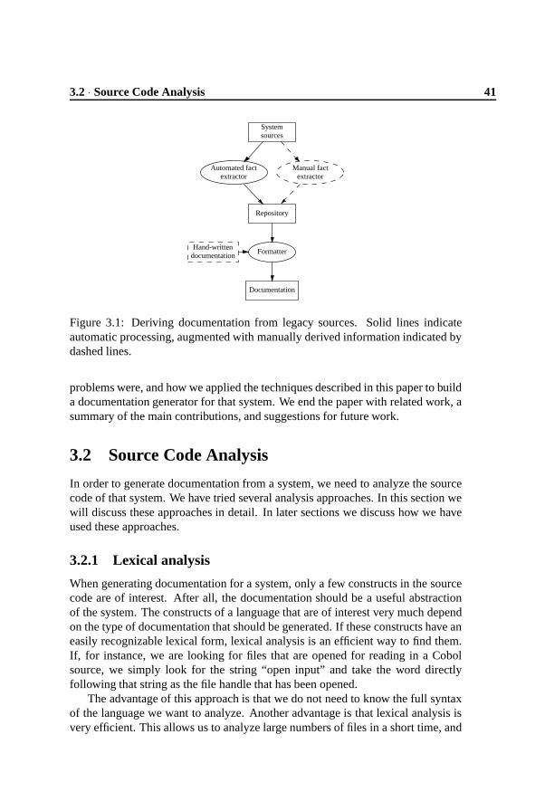
3.2 � Source Code Analysis 41
Hand-writtendocumentation
Formatter
Documentation
Systemsources
Automated factextractor
Manual factextractor
Repository
Figure 3.1: Deriving documentation from legacy sources. Solid lines indicateautomatic processing, augmented with manually derived information indicated bydashed lines.
problems were, and how we applied the techniques described in this paper to builda documentation generator for that system. We end the paper with related work, asummary of the main contributions, and suggestions for future work.
3.2 Source Code Analysis
In order to generate documentation from a system, we need to analyze the sourcecode of that system. We have tried several analysis approaches. In this section wewill discuss these approaches in detail. In later sections we discuss how we haveused these approaches.
3.2.1 Lexical analysis
When generating documentation for a system, only a few constructs in the sourcecode are of interest. After all, the documentation should be a useful abstractionof the system. The constructs of a language that are of interest very much dependon the type of documentation that should be generated. If these constructs have aneasily recognizable lexical form, lexical analysis is an efficient way to find them.If, for instance, we are looking for files that are opened for reading in a Cobolsource, we simply look for the string “open input” and take the word directlyfollowing that string as the file handle that has been opened.
The advantage of this approach is that we do not need to know the full syntaxof the language we want to analyze. Another advantage is that lexical analysis isvery efficient. This allows us to analyze large numbers of files in a short time, and
42 Building Documentation Generators � 3
also allows us to experiment with different lexical patterns: If a pattern does notyield the correct answer, the analysis can be easily changed and rerun.
The main disadvantage of lexical analysis is that it is (in general) not veryprecise, and that some language constructs are much harder to recognize lexicallythan others. For example, for the case study later discussed in this paper we needto find the files that were executed from a DCL program, the DEC job control lan-guage for VAX VMS. In DCL, we can look for the string “run”, which is the DCL
keyword for execution. If, on the other hand, we would want to know which filesare executed from a Bourne shell script, we would need to specify all built-in func-tions of the Bourne shell language. There is no special keyword for execution inthe shell, rather, it attempts to execute all words that are not built-in functions.
Strings such as “open input” and “run” obviously can occur in different con-texts, and may mean completely different things in each context. These stringscould occur in comment, for example, or inside a quoted string. Because we needto recognize different contexts in most cases, much of the original simplicity of thelexical pattern is gone. Furthermore, as long as we do not specify the full syntaxof a language, there is the risk that we may have overlooked particular contexts inwhich a pattern can or cannot occur.
Most commonly used for lexical analysis are Unix tools such as � ����� , ��
, and������� . Murphy and Notkin [MN96], describe LSME, a system which allows for thelexical specification of contexts of patterns, as well as the patterns themselves. Forthe analysis of Cobol, we have developed ������������� [DK98], which keeps trackof the global structure of Cobol, and allows the user to specify patterns typicallyrequired in a program understanding context.
3.2.2 Syntactic Analysis
More precise analysis of source code can be achieved by taking the syntactic struc-ture of the code into account, analyzing the abstract syntax tree instead of the in-dividual source code lines. This makes the context in which a particular constructoccurs explicitly available. Moreover, it abstracts from irrelevant details, such aslayout and indentation.
Unfortunately, most legacy systems are written in languages for which parsersare not readily available. Developing a grammar from which to generate such aparser requires a significant investment. As an example, Van den Brand et al.[dBSV97b] report a period of four months needed to develop a fairly completeCobol grammar.
For program understanding and documentation purposes, however, only a hand-ful of language constructs are needed, so it seems too much work to have to specifythe full grammar of a legacy language. Therefore, we propose the use of “islandgrammars”, in which certain constructs are parsed in full detail, whereas others areessentially ignored.

3.2 � Source Code Analysis 43
syntax
��������� � ���� �����(3.1)
��� ��� � ��� ��� � � �������(3.2)��������� ��� � �"!$#&%(')��*,+�#&% ��-.���,/10�2��
� � � �)�3!$#$%54)���6%87:9���!&��*<;=� � � � �������(3.3)4)���6%>�@?A�./�����BDCFE���#&GH%I� 7:9��J!$��*(3.4)K + � �"!&#$%54:���6%(3.5)K + � 4)���L%(3.6)K + � E���#$G.%(3.7)K + � �"!&#$%5':��*H+�#$%(3.8)
� -NM=O �P� -NM=O�QRMTS � � ;U� K +(3.9)
priorities
��������� ��� � �"!$#&%(')��*,+�#&% ��-.���,/10�2��� � � �)�3!$#$%54)���6%87:9���!&��*<;=� � � � ���V�1�XW
��� ��� � �Y� ��� � � ���V�1�
Figure 3.2: An example island grammar
3.2.3 Island Grammars
An island grammar consists of (1) detailed productions for the language constructswe are specifically interested in (2) liberal productions catching all remaining con-structs; and (3) a minimal set of general definitions covering the overall structureof a program.
As an example, suppose we have a simple language Z . Programs in Z consistof a list of one or more statements. For documentation generation purposes weare only interested in one statement, the “SELECT” statement. The definition ofthe island grammar is in Figure 3.2. We use the grammar definition languageSDF2 [Vis97b] for our definition.2 We can distinguish the following groups ofproductions:
� The definition of the statement of interest is on line (3), defining a a state-ment to be produced by the keywords “SELECT”, a FileHandle, “ASSIGN”,“TO”, a FileName, a possibly empty list of Options, terminated with a “.”character. Productions (4–9) define the details of the other non-terminals.
2Please note that productions in SDF2 are reversed with respect to languages like BNF. On the right-hand side of the arrow is the non-terminal symbol that is produced by the symbols on the left-hand sideof the arrow.

44 Building Documentation Generators � 3
� The liberal production catching all remaining constructs is on line (2), de-fined as any character that is not a “.” (the tilde negates the character classcontaining the period), followed by a period.
Obviously, this grammar is ambiguous, because a “SELECT” statement canbe produced by both productions (2) and (3). To resolve this, Figure 3.2defines priorities preferring production (3) to (2).
� Line (1) defines the overall structure of a program, which is defined as a listof statements.
The reason for using this grammar development technique, is that we signifi-cantly reduce the grammar development time. Another advantage is that the parsetree that is returned by the parser only contains the relevant information. We do nothave to weed through dozens of complicated structures to get to the informationwe look for.
By far the biggest advantage is the flexibility of the technique. Although somelegacy languages have a proper language definition, we have yet to see a legacysystem that does not use compiler specific extensions, or locally developed con-structs. Furthermore, most parsers for legacy systems are quite liberal in checkingtheir input, so although a program is not syntactically correct according to the lan-guage definition, it does parse, compile, and run. Using our grammar developmenttechnique, we can either ignore these specifics (by writing a catch-all productionsuch as (2) above), or add a production particular to a certain extension of thelegacy system at hand.
In principle, island grammars can be used in combination with any parser gen-erator, the best known ones being Yacc and Bison. We benefited from the use ofSDF2, which has a number of attractive characteristics.
First, SDF2 is based on scannerless parsing, in which the distinction betweenlexical scanning and parsing has disappeared. Hence, the user of SDF2 is notrestricted to regular expressions for defining lexical tokens. Moreover, explicitlexical disambiguation is permitted in the formalism.
Second, parsers for SDF2 are implemented using generalized LR parsing [Vis97a],which accepts arbitrary context-free grammars, not just LALR grammars acceptedby Yacc and Bison. This avoids the notorious shift reduce conflicts inherent to theuse of LALR grammars. A priority mechanism can be used to deal with ambigui-ties that may arise due to the use of arbitrary context-free grammars.
Last but not least, because SDF2 is a modular syntax definition language, wecan specify an island grammar in different modules. This way, for each analysis wecan have a different grammar that is an extension of a common core language. Thishelps to keep the grammars as small and concise as possible. Consider the islandgrammar developed above. Here, productions (1), (2), and (5–9) can be viewed asbeing part of the core of language Z . These can be put in a separate module. Then,

3.3 � Extracting Documentation 45
the only productions needed for our “SELECT” analysis are productions (3–4),and the priority rule, which should be defined in a different module.
3.2.4 Parse Tree Analysis
The parser generated from the grammar in the previous section will return parsetrees that can be easily analysed. The parse trees are encoded in aterm format[dBKV96]. This parse tree can be read in by a Java framework we wrote, thusgiving access to the parse tree as a Java object. The framework implements thevisitor design pattern [GHJV94], via a visitor class that can be specialized to per-form a particular analysis on the tree. This is simplified by the fact that the Javaframework has full knowledge of the island grammar that has been specified, andcontains methods for matching patterns of productions in the grammar to corre-sponding nodes in the tree.
The analysis results that are of interest can be written to a repository, and fromthere they can be combined, queried and used in the rest of the documentationgeneration process. All extractions described in Section 3.3 were performed usingthis Java parse tree analysis framework. The data extracted were put in a repos-itory. The presentations described in Section 3.4 were then generated from thatrepository.
This way of analyzing source code is similar in concept to a number of othersystems, e.g. CIAO [CFKW95], in the sense that there is a chain of analysis, filter,and presentation events. In our approach, however, we start filtering the data dur-ing the first (analysis) phase, because we only deal with those language constructsdefined in the island grammar.
3.3 Extracting Documentation
In this section, we will discuss the sort of information that should be contained insoftware documentation, and how this information can be identified in the legacysources.
3.3.1 Manual versus Automated Extraction
Given the choice between manual or automatic extraction of information fromsource code automatic extraction (for example using island grammars) is the pre-ferred option: it is consistent with the actual source code, and can be easily main-tained by automatic regeneration.
If generation is not feasible, the facts needed to construct the documentationcan be provided by hand. This may take the form of a list of programs and a one ortwo line description of their functionality. Whenever documentation is generated,data from this list is included as well. Moreover, automatic checks as to whether all

46 Building Documentation Generators � 3
Level Documentation
system overall purpose, list of subsystems
subsystempurpose, list of modules, batch jobs,databases, screens, ...
batch jobprograms started, databases accessed, fre-quency, ...
programbehavior, programs called, databases read orwritten, invoked by, parameters, ...
sectionfunctionality, external calls, sections per-formed, conditions tested, variables used, ...
Figure 3.3: Cobol system hierarchy, with associated documentation requirements
programs are indeed contained in the lists can be made whenever documentationis regenerated, encouraging programmers to keep the descriptions up to date. Theintegration of manual and automated extraction is illustrated in Figure 3.1, whichalso shows how additional forms of externally available documentation can beincluded in the resulting documentation.
3.3.2 System Decomposition
We can decompose a large software system into several layers of abstraction, rang-ing from individual procedures up to the overall system. At each level, we needdocumentation, helping us to answer questions about the purpose (why?) of a com-ponent, the subcomponents it consists of (part-of relationships), the componentsit needs to perform its tasks (uses relationships), the way in which it performs itstasks (how?), the way in which the component can be activated (usage conditions),the system requirements the component corresponds to, etc.
The actual splitting in layers of abstraction, and the corresponding documen-tation requirements, will differ from system to system. The hierarchy with associ-ated documentation requirements we use for Cobol systems is shown in Figure 3.3.
3.3.3 Aggregation and Use Relations
The parts-of and uses relationships discussed in the previous section can be easilyderived from the source code. In general, it is relatively straightforward to extractfacts about calls, database usage, screens used, etc.
A factor complicating this extraction is that many legacy systems use non-standard conventions for, e.g., calling or database access. We have seen callingconventions in which all calls were redirected via an assembly utility, and databaseaccess conventions hiding all SQL operations via a set of Cobol modules. The

3.3 � Extracting Documentation 47
flexibility of island parsing makes it particularly easy to tailor the extractors tosuch conventions.
3.3.4 System and Subsystem Partitioning
At the system level, the directory structure of program files or the naming con-ventions used usually provide a candidate partitioning into subsystems. If theseare absent, or perceived as inadequate, we use automatic subsystem classificationtechniques to arrive at a better partitioning [Lak97, DK99b]. Such alternatives canthen be added to the documentation, helping the user to see component relationsthat do not immediately follow from the actual partitioning.
In addition to the decomposition of the overall system, short descriptions of theindividual subsystems as well as of the overall behavior are needed in the docu-mentation. In many cases, such top level documentation may already be available,in which case it can be included in the documentation generation process. If it isnot, a description of the various subsystems should be added by hand.
3.3.5 Program Descriptions
In many systems, coding standards are such that each program or batch job startswith a comment prologue, explaining the purpose of this component, and its in-teraction with other components. If available, such a comment prologue is a veryuseful documentation ingredient which can be automatically extracted from thesource. Observe that it is generally not a good idea to extract all comment linesfrom a program’s source into its documentation: many comment lines are tightlyconnected to specific statements, and meaningless in isolation. Moreover, in manycases obsolete pieces of code have been “commented out”, which clearly shouldnot appear in system documentation.
3.3.6 Section Descriptions
For the sections (local procedures) of a Cobol program, it is usually not as easy toextract a description as it is for Cobol programs starting with a comment prologue.On the positive side, however, section names are generally descriptive and mean-ingful, explaining the purpose of the section. This is unlike Cobol program names,which generally have a letter/number combination as name indicating which sub-system it is part of, not what its purpose is.
Since we encountered an actual need for the documentation of sections thatconsisted of more than just the name, but at the same time was more abstractthan simply the complete source code, we decided to search for ways in which toselect the essential statements from a section. In terms of the theory of programcomprehension as proposed by Brooks [Bro83], we try to select those statements

48 Building Documentation Generators � 3
PVP550407GN.DAT
PVP550101BS.COB
PVM550103PR.DATPVM550102PR.DAT
PVP550406GN.DAT
PVP550406GN.COB
PVP550405GN.DAT
PVP550404GN.DAT
PVP550404GN.COB
PVM500901GN.DATPVM500801GN.DATPVM500701GN.DATPVM500401GN2.DATPVM500401GN1.DATPVM500501GN.DATPVM500301GN1.DATPVM501201GN.DAT
PVP500101BS.COB
PVP500101XX.DAT
PVM400406PR_ZO.DATPVM400406PR_G.DATPVM400406PR_W.DATPVM400406PR_T.DAT
PVM400406PR_NO.DAT
PVP550401SL.DAT
PVP550409GN.COB PVP550408GN.COB
PVP550409GN.DAT
PVP550408GN2.DATPVP550408GN1.DAT
PVP550401SL.COB
PVM500301GN2.DAT
PVP500102BS.COB
PVM400701SL.DAT
PVP400401BS.COB
PVM400501SL.DAT
UNRESOLVED: HERSTELDE_GEG
PVP500101XX.COB
UNRESOLVED: TE_HERSTELLEN_GEG
PVP400101IN1.DAT
Figure 3.4: An example of the visualization of data dependencies in a DCL job
that act as beacons for certain understanding tasks, such as finding out under whatcondition a certain piece of code is being executed.
Statements we include in such section descriptions are the conditions checkedin control statements, calls to external programs, database access operations, callsto other sections, statements containing arithmetic computations, and commentlines. This explicitly excludes the frequently occurring MOVE statement, whichin Cobol is an assignment from one variable to another. As it does nothing “inter-esting” (no computation) leaving it out of the documentation directs the reader’sattention to those statements that do perform some task of interest.
Following this strategy, the length of a summarized section is about one thirdof the length of its full source code. To make the summary as comprehensibleas possible, we reuse indentation of the original source code, giving the reader asense of the nesting level.
3.3.7 Batch Job Dependencies
For a Cobol mainframe application, the batch jobs determine which programs arestarted every day or night, and how datafiles used for communication purposesare sorted, renamed, etc. In many cases, the batch jobs are the least understoodcomponents of a Cobol system, in spite of their importance for the daily data pro-cessing. Documentation should help in understanding such batch jobs. We haveexperimented with visualizing the data dependencies in such batch jobs.
Finding the data dependencies for a batch job is a three step process. First, weidentify the Cobol programs executed in a batch job. Second, we analyze theseCobol programs, determining which data files are read and which ones are written.

3.4 � Presenting Documentation 49
Third, we return to the batch files, to see whether these data files occur in them,for example for sorting or renaming.
Recognizing these dependencies involves two island grammars: one for the jobcontrol language, finding the execution, sort and renaming statements, and one forCobol, identifying the data file manipulation statements.
Once the data dependencies are found, they can be visualized. The visualiza-tion of an example batch job is shown in Figure 3.4. The resulting graph onlyshows the functional dependencies: Dynamic dependencies, such as the order ofexecution, are not explicitly visible. Also observe that in some cases, it will beimpossible to determine the name of a data file, because it is determined at runtime. Special nodes in the graph are used to mark such file names.
3.4 Presenting Documentation
Once we have decided which information to put into the documentation, we candecide how to present that information to the user. Hypertext has been proposed asa natural way of presenting software documentation [Bro91, Raj97] as the hyper-links can be used to represent, for example, part of and uses relationships betweenbetween the documented components.
The most natural way of organizing all the information derived is to followthe system hierarchy, producing essentially one page per component. For Cobolthis would result in pages corresponding to the full system, subsystems, programs,batch jobs, and sections, following the decomposition of Figure 3.3.
If a user knows what programs he wants to read about, finding an initial nodeto start browsing is simple. In many cases, however, there may not be such astraightforward starting point. Therefore, we provide various indexes with entrypoints to the hypertext nodes, such as:
� Alphabetic index of program names;
� Keyword search on documentation contents;
� Graphs representing use relationships. In particular, navigating through acall graph may help to find execution starting points or modules frequentlyused. We have used the graph drawing package � ��� [GKNV93] to inte-grate clickable image maps for various call graphs and data-dependencygraphs into generated documentation. In order to prevent visual clutteringof graphs, we have applied node concentration on them, as can be seen inFigure 3.4.
� Hand-written index files, establishing links between requirements and sourcecode elements.

50 Building Documentation Generators � 3
Many presentation issues are not specific to software documentation. By usinga standard format such as HTML, the generated documentation can benefit fromvarious future developments of the Web, such as search engines, page clusteringbased on lexical affinity, link generation from textual documentation files, the useof XML to establish a better separation content from presentation, etc.
3.5 Business Case
We have used all the techniques and ideas discussed in this paper in a commer-cial project aiming at redocumenting a Cobol legacy system. In this section, wedescribe our findings.
3.5.1 Background
PensionFund is a system for keeping track of pension rights of a specific group ofpeople in the Netherlands. It consists of approximately 500 Cobol programs, 500copybooks, and 150 DEC DCL batch jobs, totaling over 600,000 lines of code.The main tasks of the system are processing pension contributions and pensionclaims.
Several years after the initial delivery, the organization responsible for Pen-sionFund decided to outsource all maintenance activities to a division of Dutchsoftware house ROCCADE, specializing in software management and maintenance.In order to make a realistic estimate of the anticipated maintenance costs involvedbefore accepting maintenance commitments, ROCCADE performed a system scanin which a number of key factors affecting maintainability are estimated.
One of the outcomes of the scan was that the documentation for PensionFundwas not adequate. In fact, documentation was not kept up to date: for exam-ple, although in 1998 a number of major PensionFund modifications were imple-mented, the documentation was never updated accordingly. Very little documenta-tion maintenance had been performed, although the need for documentation grewas more and more programmers who had participated in the original design ofPensionFund moved to other projects.
The lack of proper documentation resulted in:
� A growing backlog of major and urgent modification requests, which byearly 1999 had risen to 12.
� Difficulty in carrying out adequate year 2000 tests, since the documentationdid not help to identify the sources of errors encountered during testing.
� Difficulty in mapping modification requests, phrased in terms of desiredfunctionality modifications, onto changes to be made in actual programs.

3.5 � Business Case 51
� Difficulty in splitting the large number of daily batch jobs into clusters thatcould be run independently and in parallel, which was becoming necessaryas the increasing number and size of the batch jobs caused the required dailycompute time to grow towards the upper limit of 24 hours.
3.5.2 Documentation Wishes
To remedy these PensionFund problems, a redocumentation project was planned.The plan was to compose a number of MS-Word documents, one per program,containing:
� A short description
� Calls made (from other Cobol programs or batch jobs) to this program, andcalls made from this program;
� Database entities as well as flat files read and written;
� Dataflow diagram;
� Description of functionality in pseudo-code.
Apart from the per program documentation, per batch file one dataflow chartwas planned for. Management was willing to make a significant investment torealize this documentation.
Initially, the idea was to write this documentation by hand. This has the ad-vantage that documentation writers can take advantage of their domain or systemknowledge in order to provide the most meaningful documentation. Unfortunately,hand-written documentation is very costly and error prone. Because it is not a jobmany people like to do, it is difficult to find skilled documentation writers.
Therefore, it was decided to try to generate the documentation automatically.This has the advantages that it is cheap (the tools do the job), accurate, complete,and repeatable. If necessary, it was argued, it could be extended with manuallyderived additional information.
3.5.3 Derived Documentation
The contents requirements of the PensionFund documentation corresponds to thewishes discussed the previous section. The specific information derived per pro-gram is shown in Figure 3.5. Arriving at this list and determining the most de-sirable way of presentation was an interactive process, in which a group of fivePensionFund maintenance programmers was involved.
The fact extraction phase mainly involved finding the structure of PERFORM,CALL, and database access statements, and was implemented using island parsing.For those extraction steps for which a line by line scan was sufficient (for example,

52 Building Documentation Generators � 3
Header Content
Summary Name, lines of code, two-line descriptionActivation Batch jobs or Cobol programs called byParameters List of formal parametersData Databases and flat files read or writtenScreens List of screens sent or receivedCalls Modules and utilities calledOverview Clickable conditional perform graphSections Clickable outline for each section
Figure 3.5: Contents of the HTML document derived for each PensionFund pro-gram.
Cobol comment extraction), or for the ones which required the original layout andindentation (summarizing sections) lexical analysis was implemented using Perl.
The result of the fact extraction was a set of relations, which were combinedinto the required relations per program using Unix utilities such as join and AWK.The final production of HTML code from the resulting relation files was writtenusing Perl.
All the documentation per program could be generated automatically. Eventhe the two-line description per program could be generated, as this was an easilyrecognizable part of the prologue comment. Had this not been the case, this wouldhave required a manual step. As top level indices we generated alphabetic lists,lists per subsystem, and clickable call graphs. Moreover, we composed one indexmanually, grouping the programs based on their functionality.
As a separate top level view, we used the data dependency visualization we de-rived from the batch files. For each DCL file, we used the techniques described inSection 3.2 to find all Cobol programs that are executed. We then analyzed theseCobol programs to find the data files they read and write to. Using static analy-sis it is impossible to find all the data file names, because, in this system, somefile names were obtained dynamically. This occurs especially in error conditions,where the name of the file to write the error data to is somehow related to the kindof error. The files we could not find names for are only a small fraction of alldata files. In order to visualize these unnamed files at a later stage, we introducedspecial filenames for these files. In Figure 3.4 these unresolved filenames can beseen on the left side, and are clearly marked: “unresolved”.
The list of data files was then matched against the DCL files again, to seewhether the data was manipulated there. In the PensionFund system, we lookedat the ����� � statement, which takes one file and a number of sort parameters, andwrites to a different file. They are visualized as diamonds in the figure.
An example browsing session trough the generated documentation is shownin Figure 3.6. A typical session would be a maintenance programmer trying to

3.5 � Business Case 53
Figure 3.6: Browsing through the documentation generated for PensionFund.
find out why a particular batch job did not work as expected. He starts browsingthe visualization of the data dependencies in the batch job, follows the links to aspecific program, reads the purpose of that program, searches the perform graphfor relevant sections, ending in the section responsible for the incorrect systembehavior.
3.5.4 Evaluation
As we have demonstrated in the previous section, the documentation generatorwe have built for PensionFund exactly fulfills the wishes the PensionFund ownershad. Furthermore, the documentation that is generated adheres to the four criteriamentioned in first section of this paper. Compared to the initial plan of manuallyderiving all documentation, significant cost savings were achieved by employingdocumentation generators, even if the time needed for configuring the documenta-tion generators is taken into account.
A question of interest is whether this approach is applicable to other legacysystems as well. Our approach takes the good properties of a system in to account.For PensionFund, these are the systematic coding style which meant that certain

54 Building Documentation Generators � 3
properties (such as program descriptions) were automatically derivable from thesource. Furthermore, the programs were relatively short, which made them a nat-ural starting point for documentation generation. Another result is that the (con-ditional) perform graphs are not too big, making them easily comprehensible. Fi-nally, the fact that the sections were relatively short made the section summariesfeasible.
Although other systems may not share the desirable properties of PensionFund,they usually have some of these and possibly other strong points. Apart from theprogram description, all other documentation can be generated for any (Cobol)system. Program descriptions could then be added by hand once, such that subse-quent generation steps have this information available. It is part of our future workto see how the generation of the documentation as described here is useful in othersystems. We may decide for other systems, that certain levels of documentationare of no use, and new ones are more natural.
We believe the techniques described in this paper are flexible enough to en-able us to build different types of documentation generators for different types ofsystems rather easily.
3.6 Concluding Remarks
Related Work Chikofski and Cross define redocumentation as the creation of asemantically equivalent representation of a software system within the same levelof abstraction. Common tools include pretty printers, diagram generators, andcross-reference listing generators [CC90]. Landis et al. discuss various documen-tation methodologies, such as Nassi Schneiderman charts, flow charts and Jacksondiagrams [LHGF88].
Wong et al. emphasize structural redocumentation, which, as opposed to docu-mentation in-the-small, deals with understanding architectural aspects of software.They use Rigi for the extraction, querying, and presentation, using a graph editorfor manipulating program representations. Several views of the legacy system canbe browsed using the editor. Our approach also focuses on the structural aspectsof documentation. Rather than using a dedicated graph editor, we use standardHTML browsers for viewing the documentation. We determine the required viewsin advance, via discussion with the team of maintenance programmers.
The software bookshelf [FHK�
97] is an IBM initiative building upon the Rigiexperience. In the bookshelf metaphor, three roles are distinguished: the builderconstructs (extraction) tools; the librarian populates repository with meaningfulinformation using the building tools or other (manual) ways, and the patron isthe end user of the bookshelf. For the building phase, the parsing is like our islandapproach, in that only constructs of interest are recognized. The parsers are writtenin Emacs macros, without using an explicit grammar. The parsing code directlyemits the HTML code.

3.6 � Concluding Remarks 55
Several papers report on the use of hypertext for the purpose of documentingsoftware [Bro91, Raj97, dOBvSdPL98]. Of these, [dOBvSdPL98] follows theliterate programming [Knu84] approach as also used in, for example, Javadoc,enabling the programmer to control the generation of HTML by manually addingdedicated comment tags.
The need for flexible source code extraction tools was also recognized by, forexample, LSME [MN96], as discussed in Section 3.2.1. Another approach ofinterest is TAWK [GAM96], which uses an AWK like language to match abstractsyntax trees.
Contributions In this paper, we have described our contributions to the field ofdocumentation generation. Specific to our approach are:
� The systematic integration of manual documentation writing with automateddocumentation generation in a redocumentation setting.
� The integration of different levels of documentation abstractness, and thesmooth transition between the different levels of documentation.
� The island grammar approach to software fact extraction
� A method for building documentation generators for systems in the Coboldomain.
� The automatic visualization of data-dependencies in mainframe batch jobs.
� The application of the contributions listed above in a commercial environ-ment.
We have shown how we can build documentation generators which adhere to atleast the first three criteria from the introduction. The fourth criterion (documen-tation needs to be consistent with the source code) can only be achieved by elim-inating the need for manual documentation. By combining automatically deriveddocumentation and manually derived documentation, and by keeping the input forthe two well separated, our documentation generators only need little human inputto adhere to all four criteria.
Future Work At the time of writing, we are finalizing the PensionFund casestudy. Moreover, we are in the process of initiating other commercial redocumen-tation projects, which will help us to identify additional documentation needs andnew ways of presenting the data extracted from the sources.
On the extraction side, we plan to elaborate the ideas underlying island gram-mars. In particular, we will take a close look at the best way of expressing therequired analysis of the abstract syntax tree.

56 Building Documentation Generators � 3

Chapter 4
Identifying Objects usingCluster and Concept Analysis
The amount of facts retrieved from a legacy system by perform-ing the analyses described in the previous two chapters is enormous.Particularly when the goal of the analysis is to perform a structuralchange on the system, the retrieved facts need to be filtered, prefer-ably in an automated way. A possible change may be to move froma procedural system to an object-oriented one. This chapter explorestwo ways of filtering and interpreting the facts as obtained in the pre-vious two chapters in such a way that they become the starting pointfor an object-oriented redesign of the system.1
4.1 Introduction
In 1976, Belady and Lehman formulated their Laws of Program Evolution Dy-namics [BL76]. First, a software system that is used will undergo continuousmodification. Second, the unstructuredness (entropy) of a system increases withtime, unless specific work is done to improve the system’s structure. One possi-ble way of doing this is to migrate software systems to object technology. Objectorientation is advocated as a way to enhance a system’s correctness, robustness,extendibility, and reusability, the key factors affecting software quality [Mey97].
The migration of legacy systems to object orientation, however, is no meantask. A first, less involved, step includes merely the identification of candidate ob-jects in a given legacy system. The literature reports several systematic approaches
1This chapter was published earlier as: A. van Deursen and T. Kuipers. Identifying objects usingcluster and concept analysis. In 21st International Conference on Software Engineering, ICSE-99,pages 246–255. ACM, 1999.
58 Identifying Objects using Cluster and Concept Analysis � 4
to object identification, some of which can be partially automated. (In Section 4.2we provide a summary). There are several problems, however, with the applicationof these approaches to actual systems.
1. Legacy systems greatly vary in source language, application domain, databasesystem used, etc. It is not easy to select the identification approach best-suited for the legacy system at hand.
2. It is impossible to select a single object identification approach, since legacysystems typically are heterogeneous, using various languages, database sys-tems, transaction monitors, and so on.
3. There is limited experience with actual object identification projects, makingit likely that new migration projects will reveal problems not encounteredbefore.
Thus, when embarking upon an object identification project, one will have to se-lect and compose one’s own blend of object identification techniques. Moreover,during the project, new problems will have to be solved. This is exactly what hap-pened to us when we tried to construct an object-oriented redesign of Mortgage,a real life legacy Cobol system.
For many business appliations written in Cobol, the data stored and processedrepresent the core of the system. For that reason, the data records used in Cobolprograms are the starting point for many object identification approaches (such as[CDDF99, NK95, FRS94]).
Object identification typically consists of several steps: (1) identify legacyrecords as candidate classes; (2) identify legacy procedures or programs as can-didate methods; (3) determine the best class for each method via some form ofcluster analysis [Lak97]. This approach gives good results in as far as the legacyrecord structure is adequate. In our case study, however, records consisted of upto 40 fields. An inspection of the source code revealed that in the actual use ofthese records, many of the fields were entirely unrelated. Making this record intoa single class would lead to classes with too many unrelated attributes.
In this paper, we report on our experience with the application of some of thetechniques proposed for object identification, most notably cluster and conceptanalysis, to Mortgage. Moreover, we discuss in full detail how the unrelated-record-fields problem – not covered by any of the existing object identificationapproaches – can be addressed in general. Our approach consists of clusteringrecord fields into coherent groups, based on the actual usage of these fields in theprocedural code. We not only use traditional cluster analysis [KR90, Lak97] forthis, but also the recently proposed concept analysis [SR97, LS97].
The principal new results of this paper include:
� A proposal for usage-based record structuring for the purpose of object iden-tification;

4.2 � Related Work 59
� Significant practical experience with the use of cluster and concept analysisfor object identification;
� A discussion of a number of problems (and solutions) involving the use ofcluster and concept analysis in general;
� A comparison of the use of cluster and concept analysis for the purpose ofobject identification.
4.2 Related Work
A typical approach to finding classes in legacy code is to identify procedures andglobal variables in the legacy, and to group these together based on attributes suchas use of the same global variable, having the same input parameter types, return-ing the same output type, etc. [OT93, LW90, CCM96, Sch91]. A unifying frame-work discussing such subsystem classification techniques is provided by Lakhotia[Lak97].
Unfortunately, many of these approaches rely on features such as scope rules,return types, and parameter passing, available in languages like Pascal, C, or For-tran. Many data-intensive business programs, however, are written in languageslike Cobol that do not have these features. As a consequence, these class extrac-tion approaches have not been applied successfully to Cobol systems, as was alsoobserved by Cimitile et al. [CDDF99].
Other class extraction techniques have been developed specifically with lan-guages like Cobol in mind. They take specific characteristics into account, such asthe close connection with databases.
Newcomb and Kotik [NK95] take all level 01 records as a starting point forclasses. They then proceed to map similar records to single classes, and find sec-tions that can be associated as methods to these records. Their approach exhibitsa high level of automation, and, as a consequence, results in an object-orientedprogram that stays close to the original Cobol sources.
Fergen et al. [FRS94] describe the MOORE tool, which analyses Cobol-85code, and provides the engineer with a set of class proposals. All records aregiven a weight, which indicates the number of references made to that record. Noattempt is made at splitting up large records into smaller structures. Proposals formethods consist of Cobol paragraphs which use or modify one of the record fields,again ranked by the weight of the fields in that paragraph. To reduce the totalnumber of classes, every time a new candidate class is found, a numeric similaritymeasure is used to see whether already existing classes can be used to build thisnew candidate class.
De Lucia et al. [DDF�
97, CDDF99] describe the ERCOLE paradigm for mi-grating RPG programs to object-oriented platforms. It consists of several steps,one of which is “abstracting an object-oriented model.” This step is centered

60 Identifying Objects using Cluster and Concept Analysis � 4
around the persistent data stores. Batch programs, subroutines, or groups of call-related subroutines are candidate methods. Data stores and methods are combinedin such a way that certain object-oriented design metrics get optimal values.
Sneed and Nyary [SN95] present a tool, OBJECT-REDOC, that can be usedto derive documentation automatically from legacy sources. The documentationitself is “object-oriented”, in that it takes an object-oriented view on the legacysystem. Sneed also provides a systematic method, REORG, to transform Cobolprograms to object-oriented frames in a largely manual manner [Sne92].
Tan and Ling [TL95] present a domain-specific approach to reengineeringdata-intensive business programs. They propose the use of an augmented objectmodel, which is an extension of the object modeling technique OMT. Their modelrecovery procedure takes constants, user inputs, retrieved and updated databaserecords, and user outputs as its starting point. However, they make no attempt atsplitting up records in smaller structures.
Wiggerts et al. [WBF97] describe three different scenarios for object iden-tification. Their function-driven scenario takes legacy functionality (subsystemsperforming a certain task) as starting point for class extraction. The data-drivenapproach starts by searching for (persistent) data elements, which are likely to de-scribe business entities. The object-driven approach, finally, does not start fromthe legacy system itself, but starts by building an object model of the applicationdomain.
4.3 Field and Program Selection
Legacy systems contain data and functionality that are useful in a given applica-tion domain. Unfortunately, the legacy system also contains a significant amountof code of a technical nature, closely tied to the implementation language, oper-ating system, database management system, etc. When migrating legacy systemsto object technology, such technical code is of significantly less interest than thedomain-related code, for example because the object-oriented platform is likelyprovide facilities for dealing with the technicalities in an entirely different manner.
Therefore, a first important step in any object identification activity must be tofilter the large number of programs, procedures, records, variables, databases, etc.,present in the legacy system.
One of the main selection criteria will be whether a legacy element is domain-related or implementation-specific. This is a criterion that is not easy to derivefrom structural code properties alone. Consequently, this step may require humaninteraction, in order to take advantage of domain knowledge, application knowl-edge, systematic naming conventions, meaningful identifiers, comments, etc.
In many cases, though, structural code properties will be able to provide ameaningful selection of legacy data elements and procedures. Selection criteria tobe used may include the use of metrics, such as requiring a McCabe complexity
4.4 � Cluster analysis 61
metric between a given minimum and maximum as discussed in [CB91]. Othersmay include the classification of variables, for example according to the type theybelong to [DM98] or according to whether a variable is used to represent dataobtained from persistent data stores [CDDF99].
Our own experience with selecting domain-related data and functionality isdescribed in [DK98]. In this paper, we will use two guidelines, one for selectingdata elements and one for selecting programs. These helped to find objects in ourMortgage case study, and we expect them to work well for other systems too.
First, in Cobol systems the persistent data stores (following the terminology of[CDDF99]) contain the essential business data. Hence, the selection to be made onall records in a Cobol program is to restrict them to those written to or read fromfile. This selection can be further improved by taking the CRUD (Create, Read,Update, Delete) matrix for the system into account. Threshold values can be givento select those databases that are read, updated, deleted, or written by a minimal ormaximal number of different programs.
Second, it is important to select the programs or procedures containing domain-related functionality. An analysis of the program call graph can help to identifysuch programs. First, programs with a high fan-out, i.e., programs calling manydifferent programs, are likely to be control modules, starting up a sequence ofactivities. Second, programs with a high fan-in, being called by many differentprograms, are likely to contain functionality of a technical nature, such as errorhandling or logging. Eliminating these two categories reduces the number of pro-grams to deal with. In many cases, the remaining programs are those containing alimited, well described functionality.
4.4 Cluster analysis
The goal of this paper is to identify groups of record fields that are related func-tionally. Cluster analysis is a technique for finding related items in a data-set. Weapply cluster analysis to the usage of record fields throughout a Cobol system,based on the hypothesis that record fields that are related in the implementation(are used in the same program) are also related in the application domain.
In this section we will first give a general overview of the cluster analysistechniques we used. Then we give an overview of the cluster analysis experimentswe performed. We end the section with an assessment of our cluster experimentsand the usage of cluster analysis for object identification in general.
4.4.1 Overview
We will explain the clustering techniques we have used by going through the clus-tering of an imaginary Cobol system. This system consists of four programs, anduses one record containing nine fields. The names of these fields are put into the

62 Identifying Objects using Cluster and Concept Analysis � 4
��� ��� ��� ���NAME 1 0 0 0TITLE 1 0 0 0
INITIAL 1 0 0 0PREFIX 1 0 0 0
NUMBER 0 0 0 1NUMBER-EXT 0 0 0 1
ZIPCD 0 0 0 1STREET 0 0 1 1
CITY 0 1 0 1
Table 4.1: The usage matrix that is used as input for the cluster analysis
N T I P N NE Z S CN 0T 0 0I 0 0 0P 0 0 0 0N
� � � � 0
NE� � � �
0 0Z
� � � � 0 0 0
S� � � �
1 1 1 0C
� � � � 1 1 1
� 0
Table 4.2: The distance matrix from Table 4.1
set of cluster items. For each of the variables in the set, we determine whether ornot it is used in a particular program. The result of this operation is the matrix ofTable 4.1. Each entry in the matrix shows whether a variable is used in a program(1) or not (0).
Distance Measures
Because we want to perform cluster analysis on these data, we need to calculatea distance between the variables. If we see the rows of the matrix as vectors,then each variable occupies a position in a four dimensional space. We can nowcalculate the Euclidean distance between any two variables.
If we put the distances between any two variables in a matrix, we get a so-called distance (or dissimilarity) matrix. Such a distance matrix can be used asinput to a clustering algorithm. The distance matrix for Table 4.1 is shown inTable 4.2. Note that any relation the variables had with the programs � ��� � � � �����has become invisible in this matrix.
An overview of different distance calculations for clustering can be foundin [Wig97].
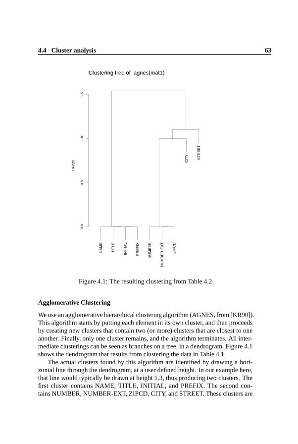
4.4 � Cluster analysis 63
NA
ME
TIT
LE
INIT
IAL
PR
EF
IX
NU
MB
ER
NU
MB
ER
-EX
T
ZIP
CD
ST
RE
ET
CIT
Y
0.0
0.5
1.0
1.5
Hei
ght
Clustering tree of agnes(mat1)
Figure 4.1: The resulting clustering from Table 4.2
Agglomerative Clustering
We use an agglomerative hierarchical clustering algorithm (AGNES, from [KR90]).This algorithm starts by putting each element in its own cluster, and then proceedsby creating new clusters that contain two (or more) clusters that are closest to oneanother. Finally, only one cluster remains, and the algorithm terminates. All inter-mediate clusterings can be seen as branches on a tree, in a dendrogram. Figure 4.1shows the dendrogram that results from clustering the data in Table 4.1.
The actual clusters found by this algorithm are identified by drawing a hori-zontal line through the dendrogram, at a user defined height. In our example here,that line would typically be drawn at height 1.3, thus producing two clusters. Thefirst cluster contains NAME, TITLE, INITIAL, and PREFIX. The second con-tains NUMBER, NUMBER-EXT, ZIPCD, CITY, and STREET. These clusters are
64 Identifying Objects using Cluster and Concept Analysis � 4
likely candidates to become classes, containing the named fields as their membervariables.
Explanation of Dendrogram
In Figure 4.1, the axis labelled “height” shows the relative distance the clustershave from each other. The variables NAME, TITLE, INITIAL, and PREFIX havea relative distance of zero (see Table 4.2), and thus form one cluster. We will callthis cluster � � . NUMBER, NUMBER-EXT and ZIPCD also have distance zero.We will call this cluster � � . No other clusters with members that have distance 0exist.
The clustering algorithm uses “average linkage” to measure the distance be-tween two clusters. This means that the distance between two clusters is the aver-age of the distances between all nodes of the one cluster, and all nodes of the othercluster. (See [Wig97] for a discussion of this and other linkage methods.) Usingthis linkage method, the closest element to cluster � � is either CITY, or STREET.They both have a distance of 1 to � � . The clustering algorithm nondeterministi-cally chooses one of CITY or STREET. In our case it chooses CITY. � � and CITYtogether form cluster ��� .
The element closest to ��� is STREET. It has a distance of� �
to CITY, and adistance of 1 to all elements of � � . So, on average, the distance between STREETand � � is
� ��� �
� � � . This new cluster we will call � � .Now, only two clusters remain: � � and � � . The distance between these two
clusters is���� � � � � � � � � ���
����� �� ����� .
4.4.2 Experimental Testbed
The input data for our cluster experiments was generated from Cobol source code,using lexical analysis tools. The data from these tools was fed into a relationaldatabase. We wrote a tool to retrieve the data from the database, and to format itfor our cluster tools. The source code was from Mortgage, a 100.000 LOC Cobolsystem from the banking area. It uses VSAM files for storing data. The toolsetused for the generation of data, and the architecture of those tools is describedin more detail in [DK98]. The Mortgage system is described in more detail in[DK98, WBF97].
For our cluster experiments we used S-PLUS, a statistical analysis packagefrom MathSoft. The cluster algorithms described in [KR90] are implemented aspart of S-PLUS.2
All experiments were performed on a SGI O2 workstation.
2The implementation is available from http://win-www.uia.ac.be/u/statis/programs/clusplusreadme.html

4.4 � Cluster analysis 65
4.4.3 Experiments
As already described in Section 4.3, we selected a number of variables and pro-grams from Mortgage to perform our cluster experiments on. In this section wewill describe our main experiment, which was executed in three steps. The resultsof the clustering experiments are shown in Figure 4.2. As stated before, we arelooking for clusters of functionally related record fields. In order to validate theuse of cluster analysis for this purpose, we need to validate the clusters found. Wehave asked engineers with an in-depth knowledge of the system to validate theclusters for us.
The (variable) names mentioned in the dendrograms of Figure 4.2 are in Dutch.We will translate the names as we explain the three dendrograms of that figure.
1. We restricted the variables to be clustered to only those occurring in the threemain records of Mortgage. This led to the dendrogram of Figure 4.2(a).There are a number of groups that seem meaningful, such as STRAAT, POSTKD,WOONPL and HUISNR (street, zip code, city and street number), or thecluster containing STREEK, LANDKD, and GEMKD (region, country code,county code). In short, this dendrogram does illustrate which variables areused together frequently, and which could therefore be grouped together.
Unfortunately, there are also a number of fields with a position that is notso easy to explain. These are in particular the ones with a “higher” posi-tion, such as INCWZ, AARD, NAAM or AANTL (payment, kind, name, andoccurrence). Also, the grouping of contact persons (KONTKT-PERS) withtelephone numbers (everything starting with TLF) is unclear.
2. The next step is to restrict the number of programs involved. Figure 4.2(b)shows the clustering results when only programs from the group of “relevantprograms” (as described in Section 4.3) were taken into account.
The result is promising, and has a simpler tree structure. However, there isan unattractively large group of fields that are lumped together, which doesnot look very meaningful. The reason for this is that there are two programsin the group of relevant programs which use all variables. Therefore theirdiscriminating capabilities in the clustering are very low.
3. We repeated the same experiment, but now without the programs which useall variables. The result is the dendrogram of Figure 4.2(c). This is a verysatisfying cluster result.
Note that the last dendrogram contains significantly less field names than the first.This makes it easier to comprehend the clusters, but also means that we have toinspect all removed variables manually for inclusion in one (or none) of the gener-ated clusters.

66 Identifying Objects using Cluster and Concept Analysis � 4
ING
DT
M
VO
OR
NM
GE
SLA
C B
GS
TK
D
GE
BD
TM
GE
BP
LT
TLF
PR
I-N
ET
TLF
PR
I-A
BO
NN
TLF
ZA
K-N
ET
TLF
ZA
K-A
BO
NN
KO
NT
KT
-PR
S1
KO
NT
KT
-PR
S2
ST
RE
EK
LA
ND
KD
AA
NH
EF S
RT
-AD
RE
S
AA
RD
RE
LAT
IEN
R
WIJ
ZIG
-DA
T
INC
WZ
BE
TIN
S-S
OO
RT B
AN
K-G
IRO
NR
BE
TIN
S-N
AA
M W
OO
NP
L-B
AN
K G
IRO
NR
-BA
NK
HY
PN
R H
YP
VLG
NR
TIT
LKD
VO
OR
VG
VO
OR
LT
HU
ISN
R-T
OE
V A
AN
TL
NA
AM
ST
RA
AT
GE
MK
D
HU
ISN
R
PO
ST
KD
WO
ON
PL
01
23
45
Hei
ght
Clustering tree of agnes(del2)
(a) Clustering using variables from threemain records of Mortgage.
WIJ
ZIG
-DA
T
HY
PN
R H
YP
VLG
NR
RE
LAT
IEN
R
AA
RD
VO
OR
NM
GE
SLA
C B
GS
TK
D G
EB
DT
M G
EB
PLT
TLF
PR
I-N
ET
TLF
PR
I-A
BO
NN
TLF
ZA
K-N
ET
TLF
ZA
K-A
BO
NN
KO
NT
KT
-PR
S1
KO
NT
KT
-PR
S2
INC
WZ
GIR
ON
R-B
AN
K B
ET
INS
-NA
AM
WO
ON
PL-
BA
NK
BA
NK
-GIR
ON
R B
ET
INS
-SO
OR
T
AA
NT
L
HU
ISN
R-T
OE
V S
TR
EE
K S
RT
-AD
RE
S L
AN
DK
D A
AN
HE
F
TIT
LKD
VO
OR
VG
NA
AM
VO
OR
LT
PO
ST
KD
WO
ON
PL
ST
RA
AT
GE
MK
D H
UIS
NR
0.0
0.5
1.0
1.5
2.0
2.5
Hei
ght
Clustering tree of agnes(del3)
(b) As Figure 4.2(a), but restricted to therelevant programs (with low fan-in andfan-out).
AA
NT
L
BA
NK
-GIR
ON
R
BE
TIN
S-N
AA
M
WO
ON
PL-
BA
NK
GIR
ON
R-B
AN
K
BE
TIN
S-S
OO
RT
INC
WZ
RE
LAT
IEN
R
HY
PV
LGN
R
WIJ
ZIG
-DA
T
HY
PN
R
TIT
LKD
VO
OR
VG
NA
AM
VO
OR
LT
PO
ST
KD
WO
ON
PL
ST
RA
AT
GE
MK
D
HU
ISN
R
0.0
0.5
1.0
1.5
2.0
Hei
ght
Clustering tree of agnes(del4)
(c) As Figure 4.2(b), but without the pro-grams which use all variables from thethree records.
Figure 4.2: Sequence of more and more refined clustering

4.4 � Cluster analysis 67
4.4.4 Assessment
We have identified two fundamental problems when using cluster analysis thisway:
1. When clustering, all items end up in exactly one cluster. However, some-times one item (one variable) is equally likely to end up in more than onecluster. For instance, two records may use the same key field. If all otherfields of the records are disjoint, and are used disjointly, we end up withthree clusters: one containing the fields of the first record, without the keyfield, one with the fields of the second record without the key field, and onewith only the key field. It is unclear whether this is the most desirable result.Perhaps we would rather have two clusters, corresponding exactly to the tworecords. Unfortunately, as items can only occur in exactly one cluster, thisis not possible using cluster analysis.
2. As we have demonstrated in our example, when we are building the clusterhierarchy, sometimes there is more than one closest cluster. Assume we havea cluster
�, which has the same distance to both clusters � and � (e.g., in
our example, both CITY and STREET had a distance of 1 to cluster � � ). Thealgorithm at that point chooses one, arbitrarily. Say the algorithm choosescluster � , thus forming cluster
���. Now cluster
���has a particular distance
to cluster � which may be very different from the distance it had had if thealgorithm had chosen � and
�to form
� �. If this happens near the leaves
of the dendrogram, the results of an arbitrary decision can be drastic.
We have partly solved these problems as follows:
1. The fields most likely to end up in more than one cluster are fields that areused together with a lot of other fields. Or, in short, the fields that are usedmost often. The system we experimented with demonstrated this property.The above mentioned key field is obviously used quite often, because ituniquely identifies a record. We have overcome the restrictions of the clusteralgorithm by removing these variables from our cluster set before startingthe cluster analysis. This proved to be a satisfactory method.
Automatic variable selection procedures in cluster algorithms have been pro-posed in the literature [FGK88]. It is a topic of future research to incorporatethese procedures in our clustering experiments.
2. We have tried to resolve the second problem by changing the distance met-rics and the linkage methods between clusters. We experimented with allmetrics and methods described in [Wig97]. However, although changingthese parameters indeed resulted in different clusters, it did not necessarilyresult in better clusters. The problem here is that it often is unclear whichof the choices is the better choice, and indeed the choice is arbitrary. What

68 Identifying Objects using Cluster and Concept Analysis � 4
sometimes is clear is that a particular sequence of choices is to be preferredabove another sequence. We have not tried to incorporate this notion into ourcluster algorithm. This would probably require some type of backtrackingmechanism, or a multiple pass algorithm, and is a topic of further research.
In conclusion we can say that cluster analysis can be used for restructuring records,given a number of restrictions. First, the number of fields to be clustered cannotbe too large. Second, the fields to be clustered should be occurring selectively inthe system (i.e., they should not be omnipresent fields, for these generate noise).Finally, there needs to be some external way to validate the clustering.
4.5 Concept Analysis
Recently, the use of mathematical concept analysis has been proposed as a tech-nique for analyzing the modular structure of legacy software [LS97, SR97, Sne98,ST98]. As with cluster analysis, we use concept analysis to find groups of recordfields that are related in the application domain.
Concept analysis and cluster analysis both start with a table indicating the fea-tures of a given set of items. Cluster analysis then partitions the set of items in aseries of disjoint clusters, by means of a numeric distance measure between itemsindicating how many features they share.
Concept analysis differs in two respects. First, it does not group items, butrather builds up so-called concepts which are maximal sets of items sharing cer-tain features. Second, it does not try to find a single optimal grouping based onnumeric distances. Instead it constructs all possible concepts, via a concise latticerepresentation.
As we will see in the next paragraphs, these two differences can help to solvethe two problems with clustering discussed in the previous section. In this section,we will first explain the basics of concept analysis. Then we will discuss its appli-cation to our Mortgage case study in full detail, followed by a comparison withthe clustering results.
4.5.1 Basic Notions
We start with a set�
of items, a set � of features,3 and a feature table (relation)��� ��� � indicating the features possessed by each item. If we reuse the data ofTable 4.1 as running example, the items are the field names, the features are usagein a given program, and the feature table corresponds to the matrix entries havingvalue 1.
3The literature generally uses object for item, and attribute for feature. In order to avoid confusionwith the objects and attributes from object orientation we have changed these names into items andfeatures.

4.5 � Concept Analysis 69
name extent intent
top�NAME, TITLE, INITIAL, PREFIX, NUMBER,
NUMBER-EXT, ZIPCD, STREET, CITY ��
c1�NAME, TITLE, INITIAL, PREFIX � � � � �
c2�NUMBER, NUMBER-EXT, ZIPCD, STREET, CITY � � ��� �
c3�STREET � � ���
,��� �
c4�CITY � � � �
,� � �
bot� � � �
,���
,���
,��� �
Table 4.3: All concepts in the example of Table 4.1
For a set of items � � � , we can identify the common features, written � ? � B ,via:
� ? � B������ �� ���� � ��� ? � � B�� ���For example, � ?��1O,/ � ��� � � ��� ��� � � B���� � � � .
Likewise, we define for � � � the set of common items, written � ? � B , as:
� ? � B���� � � � �� � �!� ? � � B�� ���
For example, � ?�� � � ��� � � B���� � �"� ��� � � .A concept is a pair
? � �#� B of items and features such that � � � ? � B and � �� ? � B . In other words, a concept is a maximal collection of items sharing commonfeatures. In our example,
?$�52�-"%�� � � / � ��� � / 2 / � / -�� � ��� �"& /' � � � � � � B
is the concept of those items having feature � � , i.e., the fields used in program � � .All concepts that can be identified from Table 4.1 are summarized in Table 4.3.The items of a concept are called its extent, and the features its intent.
The concepts of a given table form a partial order via:
? � � �(� � B�) ? � � �(� �B+* � � � � �
* � �� � �
As an example, for the concepts listed in Table 4.3, we see that bot) �-, ) � � )
top.The subconcept relationship allows us to organize all concepts in a concept
lattice, with meet . and join / defined as
? � � �(� � B . ? � � �(� �B0� ? � �21 � � �(� ? � ��1 � �
B? � � �(� � B / ? � � �(� �
B0� ? � ? � ��1 � �B �(� �31 � �
B
The visualization of the concept lattice shows all concepts, as well as the sub-concept relationships between them. For our example, the lattice is shown in Fig-ure 4.3. In such visualizations, the nodes only show the “new” items and features

70 Identifying Objects using Cluster and Concept Analysis � 4
per concept. More formally, a node is labelled with an item � if that node is thesmallest concept with � in its extent, and it is labelled with a feature
if it is the
largest concept with
in its intent.The concept lattice can be efficiently computed from the feature table; we refer
to [LS97, SR97, Sne98, ST98] for more details.
4.5.2 Experimental Testbed
To perform our concept analysis experiments, we reused the Cobol analysis archi-tecture explained in Section 4.4. The analysis results could be easily fed into the����� ����� � tool developed by C. Lindig from the University of Braunschweig.4 Weparticularly used the option of this tool to generate input for the graph drawingpackage � � � � � � ��� in order to visualize concept lattices.
4.5.3 Experiments
We have performed several experiments with the use of concept analysis in ourMortgage case study. As with clustering, the choice of items and features is acrucial step in concept analysis. The most interesting results were obtained byusing exactly the same selection criteria as discussed in Section 4.3: the items arethe fields of the relevant data records, and the programs are those with a low fan-inand fan-out. The results of this are shown in Figure 4.4, which shows the conceptlattice for the same data as those of the dendrogram of Figure 4.2(b). In order tovalidate the use of concept analysis, we need to validate the results of the conceptanalysis. Again, these results were validated by systems experts.
In Figure 4.4 each node represents a concept. The items (field names) arenames written below the concept, the features (programs using the fields) are writ-ten as numbers above the concept. The lattice provides insight in the organizationof the Mortgage legacy system, and gives suggestions for grouping programs andfields into classes.
The row just above the bottom element consists of five separate concepts, eachcontaining a single field. As an example, the leftmost concept deals with mortgagenumbers stored in the field
% � ��� 0�2 �. With it is associated program �
S �, which
according to the comment lines at the beginning of this program performs certainchecks on the validity of mortgage numbers. This program only uses the field% � ��� 0�2 �
, and no other ones.As another example, the concept
� �"� ��� �(at the bottom right) has three differ-
ent programs directly associated with it. Of these, �Q
and �Q �
compute a certainstandardized extract from a street, while program ��� takes care of standardizingstreet names.
4The ����� � ��� tool is available from http://www.cs.tu-bs.de/softech/people/lindig/.

4.5 � Concept Analysis 71
top
P4
c2
ZIPCD NUMBERNUMBER-EXT
P2
c4
CITY
P3
c3
STREET
PREFIX NAME
P1
c1
TITLE INITIAL
bot
Figure 4.3: Lattice for the concepts of Table 4.3

72 Identifying Objects using Cluster and Concept Analysis � 4
If we move up in the lattice, the concepts become larger, i.e., contain moreitems. The leftmost concept at the second row contains three different fields: themortgage sequence number
% � ��� ��� � 2 �written directly at the node, as well as the
two fields from the lower concepts connected to it,% � ��� 0�2 �
and� ����2 �
. ProgramQ�Suses all three fields to search for full mortgage and relation records.Another concept of interest is the last one of the second row. It represents the
combination of the fieldsO,/ � ���
(zip code), � ��� ��� (house number), and� / � � ���
(city code), together with� �"� ��� �
and� / � �
. This combination of five is a sepa-rate concept, because it actually occurs in four different programs ( �
S �, �S, � � � ,
� � ). However, there are no programs that only use these variables, and hence thisconcept has no program associated with it.
The largest concepts reside in the top of the lattice, as these collect all fieldsof the connected concepts lower in the lattice. For example, the concept with pro-grams � � and � � � consists of a range of fields directly attached with it (
& / � � � 2"%,
...), as well as of all those in the three downward links below it. It correspondsto almost all fields of one particularly large record, holding the data of so-calledrelations (people and companies that play a role when a mortgage is set up). Thesefields are then processed by programs � � and � � � . Only one field,
% � ��� � - �(mod-
ification date), is part of that relations record but not used in � � and � � � .Another large concept of interest is the one with programs �
S �and �
S. The
fields in this concept all come from the Dutch zip code book, holding data for allDutch addresses and their zip codes. As can be seen from Figure 4.4, the fields ofthis concept are largely disjoint with those of the relations concept (with programs� � and � � � ). However, these two concepts also share five fields, namely thoseof the
O,/ �����concept. These fields can be used (in various combinations) as the
lookup key for the zip code book.
4.6 Clustering and Concepts Compared
The application of both concept and cluster analysis to Mortgage highlights thedifferences listed below. From them, we conclude that concept analysis is moresuitable for object identification than cluster analysis.
Multiple partitionings Having a hierarchy of clusterings rather than a singlepartitioning result, is attractive as it allows one to select the most suitable cluster-ing.
At first sight, a dendrogram seems to provide exactly such a hierarchy. Un-fortunately, as we have seen in Section 4.4, the actual clusters built in the finaliterations of an agglomerative analysis strongly depend on clustering decisionsmade earlier in the analysis. It is certainly not the case that a dendrogram showsall possible clusterings.
Concept analysis, by contrast, shows all possible groupings that are meaning-ful given the feature table. In our experience, this is more helpful for the engineer

4.6 � Clustering and Concepts Compared 73
40C 40 38
STREET
37C 37
CITY
ZIPCD HOUSE CITYCD
89C 89
STR-ORD PROV-CD IND-CTY ODD ...
42
NAME
36C 36
PREFIX INITL TITLCD
29C
RELNR
19C
MORTGNR
09
MORTSEQNR
09C
BANK-GIRONR
CITY-BANK P-RELNR PAY GIRONR-BANK ...
COUNT
31C 31
FIRSTNM TELB-AREA TELB-NR TELP-AREA ...
10
MOD-DAT
10C
Figure 4.4: Concept lattice showing how persistent fields are used in programs inthe Mortgage case study.

74 Identifying Objects using Cluster and Concept Analysis � 4
trying to understand a legacy system.Items in multiple groups With cluster analysis, the result is a partitioning, i.e.,
each item is placed in exactly one cluster. In some cases, however, it is importantto group items in multiple clusters. For our type of experiments, for example,database key fields may occur in multiple records: once as primary key, and inpotentially multiple other records as foreign key.
With concept analysis, unlike clustering, this is possible. In our experiments,key fields occur as separate concepts, with separate upward links to those conceptsusing them as either primary or foreign key. In Figure 4.4, the zip code concept isan example of such a key concept.
Moreover, if concept analysis is used, it still is possible to obtain a partitioning,following an algorithm discussed in [SR97].
Features and Clusters For class extraction purposes, it is important to under-stand which features were responsible for the creation of certain clusters. Withcluster analysis, this is virtually impossible, as the analysis is solely based on thedistance matrix (see Table 4.2), in which no feature appears.
The absence of features also makes dendrograms more difficult to interpretthan concept lattices. For example, in Figure 4.4 it is clear that program �
Qis
responsible for the special status of% � � � � - �
, but in Figure 4.2(b) it is not at allobvious why
� �"� -�- �(street) appears at the top of the dendrogram.
Selection of input data The appropriate selection of input data stronly affectsthe results of both cluster and concept analysis. Cluster analysis turns out to bevery sensitive to items that possess all features. As a result, we have derived twoextra selection steps for cluster analysis: Remove programs that use all fields fromthe input data, and remove record fields that are used in all programs from theinput data.
Concept anlaysis is also sensitive to the selection of input data, but less so:therefore, we were able to derive the concept lattice of Figure 4.4 from the dataused for the dendrogram in Figure 4.2(b), rather than from the more restricteddataset used in Figure 4.2(c).
4.7 Object Identification
The final object identification step is to use the cluster and concept analysis re-sults to build object-oriented classes. Although some degree of automation maybe possible for this step, meaningful classes can be expected only if it is done inter-actively by a software engineer equipped with experience in object-oriented designas well as some knowledge of the application domain and the legacy system. Therole of cluster and concept analysis, then, is to reduce the overwhelming numberof 100,000 lines of code to a number of high-level design decisions.
When using cluster analysis, the engineer will have to decide at which heightthe clusters are to be chosen in a given dendrogram. This determines how many

4.7 � Object Identification 75
clusters exist, how large they are, and what is contained in them. Each clusterrepresents a candidate class, having the fields in the cluster as its attributes. Thecluster hierarchy present in a dendrogram also gives pointers for relations betweenthe classes. If a large cluster � is obtained by merging clusters � � � �&�$� � � � , the cor-responding class � will typically be composed from the classes for � � � �&�$� � � � viaaggregation ( � will have � attributes for fields of type � � � �$�&� � � � ). In some cases,inheritance or association may be more appropriate, but the dendrogram itself pro-vides no clues for making this decision. Cluster analysis provides no informationon which methods to attach to each of the classes identified.
When using concept analysis, the engineer can take advantage of the presenceof the programs (as features) in the lattice. An important use of the lattice is asa starting point for acquiring understanding of the legacy system. As illustratedby the discussion of the Mortgage experiment in Section 4.5, the engineer canbrowse through the lattice, and use it to select programs at which to look in moredetail.
Each concept is a candidate class. The smallest concept introducing a fieldcorresponds to the class having that field as attribute. The largest concept with agiven program as feature corresponds to the class with that program attached asmethod to it. This is reflected in the way the concepts are labeled with items andfeatures in the concept lattice. Classes close to the bottom are the smallest classes(containing few attributes).
The subconcept relationship corresponds to class relations. Typically, a classfor a concept � is composed via aggregation from the classes of the subconceptsof � . Alternatively, if a concept � has a subconcept � � , � may be composed from� � via inheritance. As an example, the concept with field
2�-"%��(and program � �
)in Figure 4.4 deals with names of persons. A natural refinement of this class isthe concept above it, which extends a person’s name with his prefixes, initials, andtitle code. Independent “columns” in the concept lattice correspond to separateclass hierarchies.
A final question of interest is whether the classes found this way are “good”classes. For Mortgage, an independent, manually developed, object-oriented re-design exists (which is partly described by [WBF97]). A good semi-automaticapproach should get as close as possible to this redesign. The lattice of Figure 4.4does not yield the complete redesign, but the concepts in the lattice constitute thecore classes of the independent redesign. One difference is that certain large “con-tainer” classes are not present in the lattice. A second difference is that in theredesign domain knowledge was used to further refine certain classes (for exam-ple, a separate “bank address” class was included). However, this separation wasnot explicitly present in the legacy system. For that reason, it was not included inthe concept lattice, as this only serves to show how fields are actually being usedin the legacy system.

76 Identifying Objects using Cluster and Concept Analysis � 4
4.8 Concluding Remarks
In this paper we have studied the object identification step of combining legacydata structures with legacy functionality. We have used both cluster and conceptanalysis for this step. Concept analysis solves a number of problems encounteredwhen using cluster analysis.
Of utmost importance with both concept and cluster analysis is the appropriateselection of the items and features used as a starting point, in order to separate thetechnical, platform-specific legacy code from the more relevant domain-relatedcode. The selection criteria we used are discussed in Section 4.3.
When searching for objects in data-intensive systems (which is the typicallythe case with Cobol systems), records are a natural starting point. We have arguedthat it is first necessary to decompose the records into smaller ones, and we haveproposed a method of doing so by grouping record fields based on their actualusage in legacy programs.
We have used this grouping problem to contrast cluster analysis with conceptanalysis. We identified the following problems with cluster analysis (see Sec-tion 4.6): (1) cluster analysis only constructs partitionings, while it is often nec-essary to place items in multiple groups; (2) a dendrogram only shows a subset(a hierarchy) of the possible partionings, potentially leaving out useful ones; (3) adendrogram is difficult to explain, as it is based on numeric distances rather thanactual features; (4) cluster analysis tends to be sensitive to items possessing allfeatures.
These limitations are inherent to clustering, and independent of the distancemeasures chosen, or the sort of items used to cluster on.
These problems are dealt with in a better way by concept analysis, making ittherefore more suitable for the purpose of object identification. Concept analysisfinds all possible combinations, and is not just restricted to partitionings. More-over, the features are explicitly available, making it easier to understand why thegiven concepts emerge.
4.8.1 Acknowledgments
We thank the members of the Object and Component Discovery Resolver taskgroup: Hans Bosma, Erwin Fielt, Jan-Willem Hubbers, and Theo Wiggerts. Fi-nally, we thank Andrea De Lucia, Jan Heering, Paul Klint, Christian Lindig, andthe anonymous referees for commenting on earlier versions of this document.

Chapter 5
Types and Concept Analysisfor Legacy Systems
In the previous chapter a starting point for an object-oriented re-design was obtained by looking at the different data elements used ina system. In this chapter, this notion is refined. Not the individualdata elements are used to perform concept analysis on, but rather theinferred types of the data elements. Type inference tries to identify agroup of data elements which are of the same type, i.e., represent thesame notion in a system. Using type inference, a large group of dataelements can be reduced to a smaller group of data types.
As this chapter has been published as a separate article earlier,we ask the reader to bear with us as some paragraphs in this chapteroverlap with paragraphs in the previous chapter.1
5.1 Introduction
Most legacy systems were developed using programming paradigms and languagesthat lack adequate means for modularization. Consequently, there is little explicitstructure for a software engineer to hold on to. This makes effective maintenanceor extension of such a system a strenuous task. Furthermore, according to theLaws of Program Evolution Dynamics, the structure of a system will decrease bymaintenance, unless special care is taken to prevent this [BL76].
Object orientation is advocated as a way to enhance a system’s correctness,
1This chapter was published earlier as: T. Kuipers and L. Moonen. Types and concept analysisfor legacy systems. In Proceedings of the International Workshop on Programming Comprehension(IWPC 2000). IEEE Computer Society, June 2000.

78 Types and Concept Analysis for Legacy Systems � 5
robustness, extendibility, and reusability, the key factors affecting software qual-ity [Mey97]. Many organizations consider migration to object oriented platformsin order to tackle maintenance problems. However, such migrations are hinderedthemselves by the lack of modularization in the legacy code.
A software engineer’s job can be relieved by tools that support remodulariza-tion of legacy systems, for example by making implicit structure explicitly avail-able. Recovering this information is also a necessary first step in the migration oflegacy systems to object orientation: identification of candidate objects in a givenlegacy system.
The use of concept analysis has been proposed as a technique for deriving(and assessing) the modular structure of legacy software [DK99b, LS97, SR97].This is done by deriving a concept lattice from the code based on data usage byprocedures or programs. The structure of this lattice reveals a modularization thatis (implicitly) avaliable in the code.
For many legacy applications written in Cobol, the data stored and processedrepresent the core of the system. For that reason, many approaches that sup-port identification of objects in legacy code take the data structures (variables andrecords) as starting point for candidate classes [CDDF99, FRS94, NK95]. Un-fortunately, legacy data structures tend to grow over time, and may contain manyunrelated fields at the time of migration. Furthermore, in the case of Cobol, thereis an additional disadvantage: since Cobol does not allow type definitions, thereno way to recognize, or treat, groups of variables that fulfill a similar role. Wecan, however, infer types for Cobol automatically, based on an analysis of theuse of variables [DM98]. This results in types for variables, program parameters,database records, literal values, and so on, which are used during analysis.
In this paper, we use the derived type information about the legacy system asinput to the concept analysis. This way, the analysis is more precise than when weuse variables or records as inputs. The concept analysis is used to find candidateclasses in the legacy system. External knowledge of the system can be used toinfluence the concepts that are calculated through ConceptRefinery, a tool we haveimplemented for this purpose.
All example analyses described are performed on Mortgage, a relation admin-istration subsystem of a large mortgage software system currently in production atvarious banks. It is a 100.000 LOC Cobol system and uses VSAM files for storingdata. The Mortgage system is described in more detail in [DK98, DM99].
5.2 Type inference for COBOL
Cobol programs consist of a procedure division, containing the executable state-ments, and a data division, containing declarations for all variables used. An exam-ple containing typical variable declarations is given in Figure 5.1. Line 6 containsa declaration of variable
�����������. Its physical layout is described as picture ���� �� ,

5.2 � Type inference for COBOL 79
which means “a sequence of 18 characters” (characters are indicated by picturecode � ). Line 18 declares the numerical variable � ����� with picture � ���� , which isa sequence of three digits (picture code � ).
The variable � ��� ��� � in line 3 is a record variable. Its record structure is indi-cated by level numbers: the full variable has level � � , and the subfields � � � � � ,� �� � , and
� ���������, are at level ��� . Line 12 declares the array �������� ��� : it is a single
character (picture ��� ��� ) occurring 40 times, i.e., an array of length 40.When we want to reason about types of variables, Cobol variable declarations
suffer from a number of problems. First of all, it is not possible to separate typedefinitions from variable declarations. As a result, whenever two variables havethe same record structure, the complete record construction needs to be repeated.2
Such practices do not only increase the chance of inconsistencies, they also makeit harder to understand the program, since a maintainer has to check and compareall record fields in order to decide that two records indeed have the same structure.
In addition, the absence of type definitions makes it difficult to group variablesthat are intended to represent the same kind of entities. On the one hand, allsuch variables will share the same physical representation. on the other hand, theconverse does not hold: One cannot conclude that whenever two variables sharethe same byte representation, they must represent the same kind of entity.
Besides these problems with type definitions, Cobol only has limited meansto indicate the allowed set of values for a variable (i.e., there are no ranges orenumeration types). Moreover, Cobol uses sections or paragraphs to representprocedures. Neither sections nor paragraphs can have formal parameters, forcingthe programmer to use global variables to simulate parameter passing.
To remedy these problems, we have proposed to infer types for Cobol auto-matically, by analyzing their use in the procedure division. In the remainder ofthis section, we summarize the essentials of Cobol type inferencing: a more com-plete presentation is given in [DM98]. First, we describe the primitive types thatare distinguished. This is followed by a description of the type relations that canbe derived from the statements in a single Cobol program, and how this approachcan be extended to system-level analysis leading to inter-program dependencies.Finally, we show how the analysis can be extended to include types for literals,discuss the notion of pollution, and conclude with an example.
Primitive Types The following three primitive types are distinguished: (1) ele-mentary types such as numeric values or strings; (2) arrays; and (3) records. Everydeclared variable gets assigned a unique primitive type. Since variable names qual-ified with their complete record name must be unique in a Cobol program, thesenames can be used as labels within a type to ensure uniqueness. We qualify vari-able names with program or copybook names to obtain uniqueness at the system
2In principle the COPY mechanism of Cobol for file inclusion can be used to avoid code duplicationhere, but in practice there are many cases in which this is not done.

80 Types and Concept Analysis for Legacy Systems � 5
� �������������� ��������� �������������������! �"�#�$�����#��%#�&���'����%#�������(���$��)�* +��-,�.�/� ������0 +�*1�%��%������2� ,���354)67+�8�9:�8 +�*�����;�. ,���354)6<��=�9:�> +�*� ���/�.�.�� ,���354)6?��@�9:�= �����@ �������������������! �"�#�$�����#��%#�&1 �A����1��������B1"�C1����#�&�$�A10�+EDF �1���HG������I���I�������������I �"�'�#�$������)���+ +��-����J�+�+�+K���� +�*!��+�+�L�����;�.�L�,���/������� +�8!��+�+�L�,��� ,���354)67+���9M��3�3�N�/� !0�+K���* +�*!��+�+�L�;���4 ,���3I �FE67+�*�9O3���;�,�L�*����2�N�.10�+K���0 +�*!��+�+�L�P���2�2�.��Q,���3I �FE67+�*�9O3���;�,�L�*����2�N�.1+K���8 �������> �1"�$�A����R �"�'�#�$�������(��� ���������(I��������G�A������)���= +��-��+�+�+K���@ +�*�����+�+ ,���3I �FE67+�*�9O3���;�,�L�*����2�N�.1+K���F +�*�����+�+ ,���3I �FE67+�*�9O3���;�,�L�*����2�N�.1+K���+��� ,�/���3�.���N�/�.!������ ����������� �!S���"� ���(�'�����(��������%#�&!G���$�AT�%#���$��������E���* /�����+�L��%���%������2� �.�3�����������0 ;����.U�%���%������2� ����I��+�+�L�����;�.�L�,���/������8 ,�.�/�P���/�;�/�*�+�+�L�3���;�,��� �.�L�����;�.V���>��= �!S���"� ���(�'�����(��������%#�&!G���$�AU������$�#���W����)���@ /���*�+�L�����;�.1 �.�3������������F ;����.I����;�.�������+�+�L�����;�.�L�,���/��V�*�+ ,�.�/�P���/�;�/�*�+�+�L�3���;�,��� �.�L�����;�.V�*��*�� �!S���"� ���(�'����HC�"��X �"�W�S�'�$���#�&I�������%'���$I��������(*�* �1"�#I$�A��!������'���"�C1$�A��!��+�+�L�����;�.�L�,���/����*�0 �!N������!��+�+�L�P��2�2�.���DY��+�+�L�;���4EDY��#�(�����+�+*�8 ��C�"��1��������B1��#�(���Z���#�&K�*�> /�*�+�+�L�3���;�,��� �.�L�����;�.I �.�3���������*�= �����*�@ ,�.�/�P���/�;!N�������2!����+�+I[���+�+�L�;���4*�F �����0�+ �%PI��+�+�L�P���2�2�.��1\I����+�+0�� �����
Figure 5.1: Excerpt from one of the Cobol programs analyzed (with some explana-tory comments added).

5.2 � Type inference for COBOL 81
level. In the remainder we will use� � to denote the primitive type of variable
�.
Type Equivalence From expressions that occur in statements, an equivalencerelation between primitive types is inferred. We consider three cases: (1) relationalexpressions: such as � ���
or � )��, result in an equivalence between
���and���
;(2) arithmetic expressions: such as � �� or � ;�� , result in an equivalence between� �
and� �
; (3) array accesses: two different accesses to the same array, such as � � � and � � � , result in an equivalence between� �
and� �
.When we speak of a type, we will generally mean an equivalence class of
primitive types. For presentation purposes, we will also give names to types basedon the names of the variables part of the type. For example, the type of a variablewith the name � ��������� � �� �� � � � � will be called � � �� �� � � � � -type.
Subtyping From assignment statements, a subtype relation between primitivetypes is inferred. Note that the notion of assignment statements corresponds toCobol statements such as � ����� ,
�� ����� ��� , ����� � ����� , etc. From an assignment ofthe form � � ���
we infer that���
is a subtype of���
, i.e., � can hold at least all thevalues
�can hold.
System-Level Analysis In addition to type relations that are inferred within indi-vidual programs, we also infer type relations at the system-wide level: (1) Types ofthe actual parameters of a program call (listed in the Cobol � � ��� clause) are sub-types of the formal parameters (listed in the Cobol � ��� � � section). (2) Variablesread from or written to the same file or table have equivalent types.
To ensure that a variable that is declared in a copybook gets the same type in allprograms that include that copybook, we derive relations that denote the origins ofprimitive types and the import relation between programs and copybooks. Theserelations are then used to link types via copybooks.3
Literals An extension of our type inference algorithm involves the analysis ofliterals that occur in a Cobol program. When a literal value � is assigned to avariable � , we infer that the value � must be a permitted value for the type of� . Likewise, when � and � are compared, value � is considered to be a permittedvalue for the type of � . Literal analysis infers for each type, a list of values thatis permitted for that type. Moreover, if additional analysis indicates that variablesin this type are only assigned values from this set of literals, we can infer that thetype in question is an enumeration type.
3Another (possibly more precise) approach would be to derive a common supertype for all versionsthat appear in different programs. Our case studies, however, showed no need for such an approach.

82 Types and Concept Analysis for Legacy Systems � 5
Aggregate Structure Identification When the types of two records are relatedto each other, types for the fields of those records should be propagated as well.In our first proposal [DM98], we adopted a rule called substructure completion,which infers such type relations for record fields whenever the two records areidentical (having the same number of fields, each of the same size). Since then,both Eidorff et al. [EHM
�
99] and Ramalingam et al. [RFT99] have published analgorithm to split aggregate structures in smaller “atoms”, such that types can bepropagated through record fields even if the records do not have the same structure.
Pollution The intuition behind type equivalence is that if the programmer wouldhave used a typed language, he or she would have chosen to give a single typeto two different Cobol variables whose types are inferred to be equivalent. Wespeak of type pollution if an equivalence is inferred which is in conflict with thisintuition.
Typical situations in which pollution occurs include the use of a single variablefor different purposes in disjunct program slices; simulation of a formal parameterusing a global variable to which a range of different variables are assigned; and theuse of a � � � � ��� � � string variable for collecting output from various variables.
The need to avoid pollution is the reason to introduce subtyping for assign-ments, rather than just type equivalences. In [DM99], we have described a rangeof experimental data showing the effectiveness of subtyping for dealing with pol-lution.
Example Figure 5.1 contains a Cobol fragment illustrating various aspects oftype inferencing. It starts with a data division containing the declaration of vari-ables. The second part is a procedure division containing statements from whichtype relations are inferred.
In line 40, variable ������ � ��� � � is compared to � ����� , which in line 38 is com-pared to ����������� . This results in an equivalence class between the primitive typesof these three variables. Observe that these three variables are also declared withthe same picture (in lines 13, 14, and 18).
In line 29, we infer from the assignment that the type of � �� � is a subtype ofthe type of � �� � ���� ��� . From line 24, we infer that � � ��� � is a subtype of of� �� � ���� ��� as well, thus making � �� � � �� ��� the common supertype of the othertwo. Here the three variables are declared with different pictures, namely stringsof different lengths. In fact, � � � ���� ��� is a global variable simulating a formalparameter for the
� ������� �� ��� ��� � � � �� � (Cobol does not support the declaration ofparameters for procedures). Subtyping takes care that the different sorts of actualparameters used still have different types.

5.3 � Concept Analysis 83
Items�
Features � � � � � � � �NAME �TITLE �INITIAL �PREFIX �CITY � �STREET � �NUMBER �NUMBER-EXT �ZIPCD �
Table 5.1: The list of items and their features
items features0 zipcd number-ext number street city prefix initial
title name1 zipcd number-ext number street city p42 street p4 p33 city p4 p24 prefix initial title name p15 p4 p3 p2 p1
Table 5.2: All concepts identified for Table 5.1.
5.3 Concept Analysis
Concept analysis4 is a mathematical technique that provides a way to identifygroupings of items that have common features [GW99]. It starts with a context:a binary table (relation) indicating the features of a given set of items. From thattable, the analysis builds up so-called concepts which are maximal sets of itemssharing certain features. The relations between all possible concepts in a binaryrelation can be given using a concise lattice representation: the concept lattice.
Recently, the use of concept analysis has been proposed as a technique foranalyzing legacy systems [Sne98]. One of the main applications in this context isderiving (and assessing) the modular structure of legacy software [DK99b, LS97,SR97, ST98]. This is done by deriving a concept lattice from the code basedon data usage by procedures or programs. The structure of this lattice revealsa modularization that is (implicitly) available in the code. In [DK99b], we usedconcept analysis to find groups of record fields that are related in the applicationdomain, and compared it with cluster analysis.
In the remainder of this section we will explain concept analysis in more detail.
4This section overlaps with Section 4.5, because both chapters were published as separate articles.

84 Types and Concept Analysis for Legacy Systems � 5
5.3.1 Basic Notions
We start with a set�
of items, a set � of features,5 and a binary relation (table)� � � � � indicating the features possessed by each item. The three tuple? � � � � � B is called the context of the concept analysis. In Table 5.1 the items arethe field names, and the features are usage in a given program. We will use thistable as example context to explain the analysis.
For a set of items � � � , we can identify the common features, written � ? � B ,via:
� ? � B2��� � � �� � � ��� ? � � B�� ���For example, � ?�� O,/ � ��� � � �"� ��� � � B���� ��� � .
Likewise, we define for � � � the set of common items, written � ? � B , as:
� ? � B2� � � � � �� �� � � ? � � B�� � �
For example, � ?�� � � � � � � B���� � �"� ��� � � .A concept is a pair
? � �(� B of items and features such that � � � ? � B and � �� ? � B . In other words, a concept is a maximal collection of items sharing commonfeatures. In our example,
?�� ��� �"& /' � / 2 / � /(-�� � � / � ��� � 2�-�%�� � � � � � � B
is the concept of those items having feature � � , i.e., the fields used in program� � . All concepts that can be identified from Table 5.1 are summarized in Table 5.2.The items of a concept are called its extent, and the features its intent.
The concepts of a given table are partially ordered via:
? � � �(� � B�) ? � � �#� �B * ? � � � � �
* � �� � � B
As an example, for the concepts shown in Table 5.2, we see that� � � � ) � , )
� ) ��� ��� .This partial order allows us to organize all concepts in a concept lattice, with
meet . and join / defined as
? � � �(� � B . ? � � �#� �B � ? � � 1 � � �(� ? � � 1 � �
B? � � �(� � B / ? � � �#� �
B � ? � ? � � 1 � �B �#� � 1 � �
B
The visualization of the concept lattice shows all concepts, as well as the rela-tionships between them. For our example, the lattice is shown in Figure 5.2.
In such visualizations, the nodes only show the “new” items and features perconcept. More formally, a node is labeled with an item � if that node is the smallest
5The literature generally uses object for item, and attribute for feature. In order to avoid confusionwith the objects and attributes from object orientation we have changed these names into items andfeatures.

5.4 � Combine Types and Concepts 85
c0features:items:
c1features: P4
items: ZIPCDNUMBER-EXT
NUMBER
c4features: P1
items: PREFIXINITIALTITLENAME
c2features: P3
items: STREET
c3features: P2items: CITY
c5features:items:
Figure 5.2: Lattice for the concepts of Table 5.2.
255
256258262 436
437454492
511
520
709
767
769
780
0
1
2 5
12
15
1623
3536
37
38
39
44 52
72
83
89
91
98
125
129
131
135
142
185
187
189
191
192
196
202
204 205208
211
212
214226
232
233
235
260 275
281
296
298
326
332
343
358
364
367
371
373
376
378
383
429
450
452 479
538
540
543
554
568
613
657
667
668
690 693
771
776
803
905 907 953 956 957
257259
267
439
440496512
513
518
733
768
783
4 6
43
184 190195 197261
268
442
539
735
966
3 779
86102
115
122
285
335
931 932935
269
444
514
515516
833
770
18
19
47 123
287
325
369
270
446517 524 531834
772773
8
10
21 48
941
835
778
782
271
451522525836
774777 788
210
263
272
677
519521
847
789
689
274
628
683
527
850
775
802
9
688
264
266
553
528852
902
1434
265
602 533
860
952
11 13
277
608
526866
817
186279
330
632
523
534867
779
849
374
638
535868
375
641
529
870
781
946
643
871
818
17 25
45 4954
93221
294
848
276
656
872
27
273679
873
784
20 28
46 58222 282
680
874
785
50
685
530
532
875
786
787
944
29
289
942
876
22 3059
290
536
877
51
278 338
878
3160
372879
790
791 792798
24231
280 382880797
799
26
881
283306
537
897
793
794 795
293
284
425
951
796 883
939940
888
32216
541
892
291
286542
658
33
288
426
427
692
695
697
700
659
544
557
607
327 380
545 547
705
800
801
947
292
546
548
706
428
549701
124
665
649
717
804
911912
550
718
805
913 295
713721
41
90
106
130
143 198 200 206 209
307309
551
558
603
806
807 962963 40
53 6177
92
138
146
161
300 313
323
334405
423
737
926
552560 604 808
950 42
73
141304 297 331
561 605 810
111144147 310
305
562 724
809
920119
148
299 385
555 728
301
556
811
812
75
317389
76
302
559
813
82
303311
814
337
312 328
655
815
74
321
633725816
859
55
6294
324
329
642726
56 95
316
420
691 694699
727
57 63308
318
563
564 579
819
431
379
565 580
820
64
84 419433
927
319 386567 583
821
67
320 390
566
581 589
734
822
65
78
322 399
582
592
823
824
825
80
401
569
6681
314
570 572 576
614 68
315
571 574 577
826
6987430
575
578 615
730
827
71 88
573
616
744
828
424
594
829
96
830
831
97
595
731
117
619
832
70 104
463
105
620
732 743
107
622
745
894 895896
116600
837
118
601
838584
839
586 588739
840
585
841
598741
842
99
410
587
843
100
333
898
593 611 844
449
590
645
845
101
406
591
846
336
934
599
103
612742
85
112 422661339
340
341361
596
851
120
342
363
597 617
113
618 853
114
625 854
344
355
402
408
855
357
403
414
653746
856 365366
345
346
350
353
606
857
347
485
749
858
434
348349
487
637
395
435
351
483
488
490
646
861
354
652
862
352
623
750 863
751
864
960
609
610
865
384
356
621
109
396445
110
359 624
360
869
901
362
108
411 441
387
412
413 443
388
368
391 370377
121
392
626
627 647 648
882
933 936
381
629630
884
929
631
885
930
634
651
886
636
887
509
889
945
639
890
635
891
640
126
127
893
128 188
644
393
183
394
397
132
236
670
671
416
447
899
133948
398448
900
134
136
152156
162
217 237
481
137
153
155
163
218
238
432
698
400
903
165170
178
223 242
904
164 166
180
225243
650
139175
407
421
404
906140
409 145
908
150415
909
417
654
910
151
154
418
959
149
660
167
914
168
915
174
662 663
916
177
917
918
160
919
157
664
921
158
666
922
159169
462
672
669
923171510675
924
172456
673
925
173458 938
949
674686
928
484
486
176
676 681702
182
489
678682703 707
684
943
964
453
714
937
179
715 719
696
460
461
687
753
759
711
491
181
438 455
465 472
493
729
494
457495
474
497498
499 500 954
459501
955
502
203
503
704 504
958
194
478505
708755 762
193 207
506716
507
961
199
508
480
710720
965
201
722
466 473
712
723
464467
469
766 470
475
482
468
476
477
213
471
215
234
219239
752
758
220
224
240
227 229
241
254 244
230
245
246
736 756
247
228248
738
740748
249
250
747
251
252
253
757
754 760761
764765
763
Figure 5.3: Types as items, program using type as feature
concept with � in its extent, and it is labeled with a feature
if it is the largestconcept with
in its intent.
For a thorough study of the foundations of concept analysis we refer the readerto [GW99].
5.4 Combine Types and Concepts
In [DK99b] concept analysis was used to find structure in a legacy system. Thevariables of a Cobol system were considered items, the programs features, and the“variable used in program” property as a relation. Table 5.1 is an example of such a

86 Types and Concept Analysis for Legacy Systems � 5
relation, and Figure 5.2 show the corresponding lattice. This lattice can be seen as acandidate object oriented design of the legacy system. The concepts are individualclasses and related concepts can be seen as subclasses or class associations.
The identification of variables in different programs was performed by compar-ing variable names, and variable declarations. If two variables shared a particularsubstring they were considered equal. This works well for systems that employ acoding standard which forces similar names for similar variables but fails horriblyfor systems where variable names are less structured. In this paper this problemis solved by taking the types (as described in Section 5.2) of these variables, andrelating them to programs in various ways.
5.4.1 Data for Concept Analysis
Before describing the concept experiments performed, first the relations derivedfrom the legacy source will be explained. The four extracted relations are varUsage,typeEquiv, transSubtypeOf and formalParam. varUsage is the relation be-tween a program and the variables that are used in that program. typeEquiv is therelation between a type name (the name of a type equivalence class) and a variablethat is of this type. transSubtypeOf is the relation between a type and the tran-sitive closure of all its supertypes, i.e. between two types where the second is inthe transitive closure of all the supertypes of the first. formalParam is the relationbetween a program and the types of its formal parameters. An overview of theserelations is given in Table 5.3.
In the remainder of this section the set of all programs, variables, and types ina system will be denoted � ,
�, and�
, respectively.
5.4.2 Experiments Performed
Type Usage
The first experiment performed is exactly the experiment performed in [DK99b],as described earlier. The type usage per program is taken as the context relation,instead of variable usage. This results in a lattice where the programs that useexactly the same set of types will end up in the same concept, programs that use
Relation name Name of relation elementvarUsage program variabletypeEquiv type variabletransSubtypeOf sub superformalParam program type
Table 5.3: Derived and inferred relations

5.4 � Combine Types and Concepts 87
0
1
26
4712
3 8
9
5
1011
13 14
15
items features01 1.firstnm[] 1.telb-area
1.telb-nr 1.telp-area 1.telp-nr1.contact-prs2 1.contact-prs11.sex 1.plbirth 1.cvlcd1.openg
31c31
2 10c3 104 4.city-bank 4.pay
4.acctnr-bank 4.pay-type4.paysoc-name 4.acctnr1.city-bank 1.acctnr-bank1.pay-type 1.paysoc-name1.acctnr
5 4.mortseqnr 4.mortgnr 0909c
6 1.variable[] 227 1.region[] 1.street[]
1.addr-type[] 1.zipcd[]1.countrycd[] 1.house-ext[]1.citycd[] 1.birthdt 1.type1.count
89 1.mod-dat10 4.relnr 1.p-relnr11 1.city[] 1.house[] 89c
8912 1.prefix 1.initl 1.titlcd 36c
3613 1.fixed 1.name14 1.startdt[] 12c15
Figure 5.4: Concepts involving relevant programs
less types will end up in a concept below, and programs that use more types willend up in a concept above that concept.
In order to arrive at the type usage concept lattice the varUsage table is takenas a starting point. For each variable, its type is selected from typeEquiv suchthat the result is a set of relations
������������ ����������������varUsage
�����������typeEquiv � . Then the types are considered items, and the programs features andthe concept analysis is performed. For the example Mortgage system, the result-ing concept lattice is shown in Figure 5.3. The list of items and features is notshown for (obvious) lack of space.
Filtering This picture may not be as insightful as we might hope. A way to de-crease the complexity of this picture is by filtering out data before performing the

88 Types and Concept Analysis for Legacy Systems � 5
concept analysis. A selection of relevant programs from all programs in a Cobolsystem can be made as described in [DK98]. Cobol systems typically contain anumber of programs that implement low-level utilities such as file I/O, error han-dling and memory management. These programs can in general be left out of theanalysis, particularly when we are only interested in the general structure of thesystem.
Filtering out insignificant variables is also possible. Typically, certain recordsin a Cobol system contain all data that has to do with customers (and therefor isprobably relevant) while other records may only be used as temporary storage.
Suppose a list of relevant programs is selected and only the data that originatedfrom a certain set of records is deemed interesting. The first step, filtering out theuninteresting programs, is easy. All tuples from varUsage that have an irrelevantprogram as their program element are simply ignored. Suppose � ����� with � ����� �� is the set of relevant programs which is derived in some way. Then all typesthat are related to the interesting variables need to be determined. Suppose
� �����with
� ����� � �is the set of all relevant variables. From the relation typeEquiv all
types that are related to a relevant variable are selected. If� ����� with
� ����� ��� isthe set of all relevant types:
��� � � ?� � � B � typeEquiv � � � � ����� � Then the typeequivalent variables that are used in the selected relevant programs are selected:��? � �� B�� � ����� � � ����� ? � � �� B�� varUsage � ?� � � � B�� typeEquiv � ��� � ����� �
The result of the experiments with filtered data are much more comprehensiblethan those without filtering, basically because there are less concepts to try to un-derstand. Figure 5.4 shows the concept lattice for the same system as in Figure 5.3,but with irrelevant programs filtered out according to [DK98]. The relevant dataare the fields of the two records describing the persistent data in the system.
The lattice in Figure 5.4 contains some unexpected combinations. Concept 7for instance, contains items that have to do with locations and addresses, but alsoa birth date. Close inspections reveals that this is not a case of type pollution, butthese variables are really used in both program 31(c) (from concept 1) and program22 (from concept 6). A possible explanation could be that these programs sendbirthday cards.
It is important to have some way to validate these lattices externally, to perfectthe filter set. For our example system, one program implements a utility routinethrough which a lot of variables are passed, causing one type to contain a remark-able large number of variables. When we filtered out that program, the resultinglattice was much more intuitive.
Parameter Types
Experiments have been performed on another concept analysis context; the con-text that has programs as items and the types of their formal parameter as features.When concept analysis is performed on this data set, all programs that share ex-actly the same set of parameter-types end up in the same concept. If two programs

5.4 � Combine Types and Concepts 89
0
1 2 3 4 5
6
items features
01 41 1.1.city[]2 40 1.1.street[]3 36c 35030u 31c 10c 05010r 01410u 01330u 01230u 1.1.record4 36 1.1.fixed5 31 10 09 1.1.p-relnr6
Figure 5.5: Programs as items, parameters as features
share some parameter-types, but not all, the shared parameter types will end up inthe same concept. These will then form an excellent basis for developing an objectoriented view on the system, as the shared types can be seen as the attributes of aclass sharing programs as methods.
In its simplest version the items and features for these concepts are computedby just taking formalParam and ignoring the subtype relationship.
As was described in Section 5.2, the relation between actual parameter typesand formal parameter types is inferred as a subtype relation. If the subtype rela-tionship is ignored, then variables can only be identified as having the same typein different programs, when they are “passed” through a copybook. That is, if avariable is included in two different programs from the same copybook, it is con-sidered type equivalent in the two programs. Obviously, this is not the intuitionwe have when looking at formal parameters, where we would like to know howthe types used in the calling program propagate to the called program. Therefor,subtyping is considered as type equivalence when looking at parameter types.
The context for parameter type usage per program while considering super-types as equivalent is derived as follows:��?
�� � B � � � � ? � �DB � formalParam � ?D?J?� � � �DB � transSubtypeOf . ?�� � � � B �typeEquiv
B / ?� � � B � typeEquivB �
.As described in the previous section, data may be filtered on either relevant
programs or relevant data elements. In that case the context is arrived at as fol-lows:
��? � � B � � ����� � � ����� ? � � � B � formalParam,
?J?D?� � � �DB � transSubtypeOf. ?�� � � � B � typeEquiv
B / ?�� � � B � typeEquivB �
for some externally determinedvalue of � ����� and
� ����� .
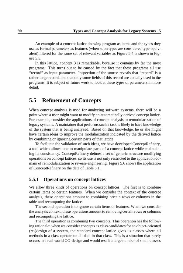
90 Types and Concept Analysis for Legacy Systems � 5
An example of a concept lattice showing program as items and the types theyuse as formal parameters as features (when supertypes are considered type equiv-alent) filtered for the same set of relevant variables as Figure 5.4 is shown in Fig-ure 5.5.
In this lattice, concept 3 is remarkable, because it contains by far the mostprograms. This turns out to be caused by the fact that these programs all use“record” as input parameter. Inspection of the source reveals that “record” is arather large record, and that only some fields of this record are actually used in theprograms. It is subject of future work to look at these types of parameters in moredetail.
5.5 Refinement of Concepts
When concept analysis is used for analyzing software systems, there will be apoint where a user might want to modify an automatically derived concept lattice.For example, consider the applications of concept analysis to remodularization oflegacy systems. A maintainer that performs such a task is likely to have knowledgeof the system that is being analyzed. Based on that knowledge, he or she mighthave certain ideas to improve the modularization indicated by the derived latticeby combining or ignoring certain parts of that lattice.
To facilitate the validation of such ideas, we have developed ConceptRefinery,a tool which allows one to manipulate parts of a concept lattice while maintain-ing its consistency. ConceptRefinery defines a set of generic structure modifyingoperations on concept lattices, so its use is not only restricted to the application do-main of remodularization or reverse engineering. Figure 5.6 shows the applicationof ConceptRefinery on the data of Table 5.1.
5.5.1 Operations on concept lattices
We allow three kinds of operations on concept lattices. The first is to combinecertain items or certain features. When we consider the context of the conceptanalysis, these operations amount to combining certain rows or columns in thetable and recomputing the lattice.
The second operation is to ignore certain items or features. When we considerthe analysis context, these operations amount to removing certain rows or columnsand recomputing the lattice.
The third operation is combining two concepts. This operation has the follow-ing rationale: when we consider concepts as class candidates for an object-oriented(re-)design of a system, the standard concept lattice gives us classes where allmethods in a class operate on all data in that class. This is a situation that rarelyoccurs in a real world OO-design and would result a large number of small classes

5.6 � Implementation 91
that have a lot of dependencies with other classes. The combination of two con-cepts allows us to escape from this situation.
On the table underlying the lattice the combination of two concepts can becomputed by adding all features of the first concept to the items of the second andvice versa.
5.5.2 Relation with source
When a concept lattice that was previously derived from a legacy system is manip-ulated, the relation between that lattice and the code will be weakened:
� Whenever features, items or concepts are combined, the resulting lattice willrepresent an abstraction of the source system.
� Whenever features or items are ignored, the resulting lattice will represent apart of the source system.
The choice to allow such a weakening of this relation is motivated by the factthat we would rather be able to understand only part of a system than not being ableto understand the complete system at all. However, in order for ConceptRefineryto be useful in a real-world maintenance situation, we have to take special care toallow a maintainer to relate the resulting lattice with the one derived directly fromthe legacy code. This is done by maintaining a concise log of modifications.
5.6 Implementation
We have developed a prototype toolset to perform concept analysis experiments.An overview of this toolset is shown in Figure 5.7. The toolset separates sourcecode analysis, computation and presentation. Such a three phase approach makesit easier to adapt to different source languages, to insert specific filters, or to useother ways of presenting the concepts found [DK98, DM98].
In the first phase, a collection of facts is derived from the Cobol sources.For that purpose, we use a parser generated from the Cobol grammar discussedin [dBSV97a]. The parser produces abstract syntax trees that are processed usinga Java package which implements the visitor design pattern. The fact extractor is arefinement of this visitor which emits facts at every node of interest (for example,assignments, relational expressions, etc.).
From these facts, we infer types for the variables that are used in the Cobolsystem. This step uses the Cobol type inferencing tools presented in [DM99]. Thederived and inferred facts are stored in a MySQL relational database [YRK99].
In the next phase, a selection of the derived types and facts is made. Sucha selection is an SQL queries that results in a table describing items and theirfeatures. A number of interesting selections were described in Section 5.4. The
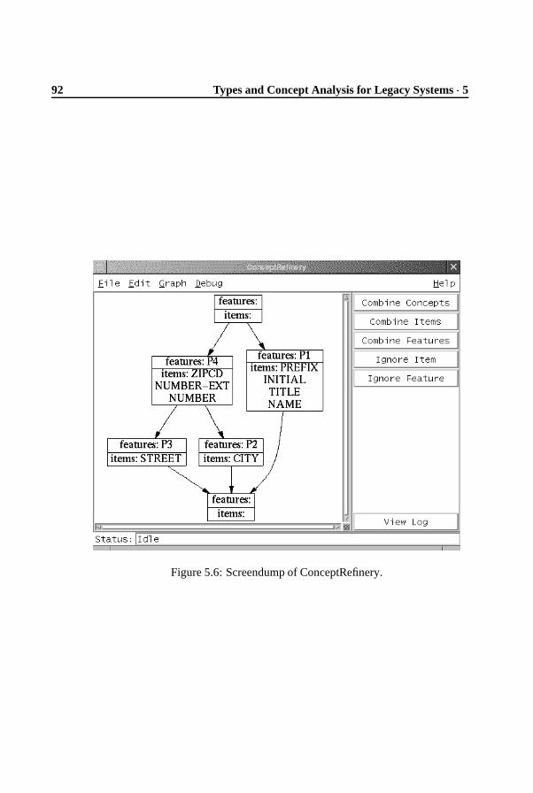
92 Types and Concept Analysis for Legacy Systems � 5
Figure 5.6: Screendump of ConceptRefinery.

5.6 � Implementation 93
Cobolsources
FactExtraction
Facts
TypeInference
Item/FeatureSelection
Types Repository
ConceptAnalysis
ConceptLattice
ConceptRefinement
ConceptVisualisation
Figure 5.7: Overview of the toolset.
results of these selections are stored in a repository. Currently, this is just a file ondisk.
In the final phase, the contents of the repository are fed into a concept analysistool, yielding a concept lattice. We make use of the concept analysis tool that wasdeveloped by C. Lindig from the University of Braunschweig.6 The concept latticecan be visualized using a tool that converts it to input for dot [GKNV93], a systemfor visualizing graphs. The lattices in Figures 5.2, 5.5, 5.3 and 5.4 were producedthis way.
Furthermore, the lattice can be manipulated using ConceptRefinery. This toolallows a user to select items, features or concepts and perform operations on thatselection. These operations result in updates of the repository. We distinguish thefollowing manipulations and describe the actions that are carried out on the repos-itory: (1) combining items or features is done by merging corresponding columnsor rows in the repository; (2) ignoring items or features is done by removing cor-responding columns or rows in the repository; (3) combining concepts is done byadding all features of the first concept to the items of the second and vice versa.The user interface of ConceptRefinery is shown in Figure 5.6. On the left handside a visualization of the concept lattice is given. The items, features or conceptsthat need to be modified can be selected in this lattice. The right hand side showsall available operations. ConceptRefinery is implemented in Tcl/Tk [Ous94] andTcldot: an extension for Tcl/Tk that incorporates the directed graph facilities ofdot into Tcl/Tk and provides a set of commands to control those facilities.
6The tool “ ����� � ��� � ” is available from http://www.cs.tu-bs.de/softech/people/lindig/.

94 Types and Concept Analysis for Legacy Systems � 5
5.7 Related Work
Several methods have been described for modularizing legacy systems. A typicalapproach is to identify procedures and global variables in the legacy, and to groupthese together based on attributes such as use of the same global variable, hav-ing the same input parameter types, returning the same output type, etc. [CCM96,LW90, OT93, Sch91]. A unifying framework discussing such subsystem classifi-cation techniques is provided by Lakhotia [Lak97].
Many of these approaches rely on features such as scope rules, return types,and parameter passing, available in languages like Pascal, C, or Fortran. Manydata-intensive business programs, however, are written in languages like Cobolthat do not have these features. As a consequence, these class extraction ap-proaches have not been applied successfully to Cobol systems [CDDF99]. Otherclass extraction techniques have been developed specifically with languages likeCobol in mind. They take specific characteristics into account, such as the struc-ture of data definitions, or the close connection with databases [CDDF99, FRS94,NK95]. The interested reader is referred to [DK99b] for more related work onobject identification.
Concept analysis has been proposed as a technique for analyzing legacy sys-tems. Snelting [Sne98, Sne00] provides an overview of various applications. Ap-plications in this context include reengineering of software configurations [Sne96],deriving and assessing the modular structure of legacy software [LS97, SR97], ob-ject identification [DK99b], and reengineering class hierarchies [ST98].
The extract-query-view approach adopted in our implementation is also usedby several other program understanding and architecture extraction tools, such asCiao [CFKW95], Rigi [WTMS95], PBS [SCHC99], and Dali [KC99].
New in our work is the addition of the combination of concept analysis andtype inferencing to the suite of analysis techniques used by such tools. Our ownwork on type inferencing started with [DM98], where we present the basic theoryfor Cobol type inferencing, and propose the use of subtyping to deal with pollu-tion. In [DM99], we covered the implementation using Tarski relational algebra,as well as an assessment of the benefits of subtyping for dealing with pollution.Type-based analysis of Cobol, for the purpose of year 2000 analysis, is presentedby [EHM
�
99, RFT99]: both provide a type inference algorithm that splits aggre-gate structures into smaller units based on assignments between records that crossfield boundaries. The interested reader is referred to [DM98, DM99] for morepointers to related work on type inferencing.
5.8 Concluding remarks
In this paper we have shown that the combination of facts derived from legacysource code, together with types inferenced from those facts, forms a solid base

5.8 � Concluding remarks 95
for performing concept analysis to discover structure in legacy systems. This ex-tends and combines our previous work on type inferencing for legacy systems andobject identification using concept analysis. We implemented a prototype toolsetfor performing experiments. From these experiments, we can conclude that thecombination of type inference and concept analysis provides more precise resultsthan our previous concept analyses which did not involve types.
The combinations discussed in this paper are the following concept analysiscontexts:
1. type usage per program
2. types of parameters per program
The latter analysis appears to be particularly suitable as a starting point for anobject oriented redesign of a legacy system.
When performing concept analysis to gain understanding of a legacy system, itproves very helpful if the reengineer is able to manipulate the calculated conceptsto match them with his knowledge of the system, or to remove parts he know to beirrelevant. We have implemented ConceptRefinery, a tool that allows a softwareengineer to consistently perform this kind of modifications while maintaining arelation with both the original calculated concepts, and the legacy source code.
5.8.1 Future work
We would like to extend ConceptRefinery to propose a grouping of concepts tothe human engineer to consider when refining the lattice. To this end, we will toexperiment with applying cluster analysis algorithms to the concept lattice.
We have discussed two particular concept analysis contexts in this paper. Wewould like to see whether we could use the results of one of these concept analysesto improve the results of the other. I.e. to take the concept found by looking atthe parameter types of programs and somehow use those to mark relevant andirrelevant concepts from the variable usage analysis.
Acknowledgments The many pleasant discussions we had about this paper withArie van Deursen are greatly appreciated. We thank Joost Visser for his commentson earlier drafts of this paper.

96 Types and Concept Analysis for Legacy Systems � 5

Chapter 6
Object-Oriented TreeTraversal with JJForester
The results presented in the previous chapter can only be achievedwith data obtained from highly detailed analyses. In Chapter 3, is-land grammars were introduced to facilitate these analyses. However,when a system is parsed using a parser generated from a (island) gram-mar, the resulting parse tree needs to be analyzed. In this chapter, atechnique for traversing and analyzing parse trees is developed. Fur-thermore, a case study of how to use the technique for the analysis ofa software system is presented.1
6.1 Introduction
JJForester is a parser and visitor generator for Java that takes language defini-tions in the syntax definition formalism SDF [HHKR89, Vis97b] as input. It gen-erates Java code that facilitates the construction, representation, and manipula-tion of syntax trees in an object-oriented style. To support generalized LR pars-ing [Tom85, Rek92], JJForester reuses the parsing components of the ASF+SDFMeta-Environment [Kli93].
The ASF+SDF Meta-Environment is an interactive environment for the devel-opment of language definitions and tools. It combines the syntax definition formal-ism SDF with the term rewriting language ASF [BHK89]. SDF is supported withgeneralized LR parsing technology. For language-centered software engineering
1This chapter was published earlier as: T. Kuipers and J. Visser. Object-oriented Tree Traversalwith JJForester. In Proceedings of the First Workshop on Language Descriptions, Tools and Appli-cations 2001 (LDTA’01). Electronic Notes in Theoretical Computer Science 44(2). Elsevier SciencePublishers, 2001.

98 Object-Oriented Tree Traversal with JJForester � 6
applications, generalized parsing offers many benefits over conventional parsingtechnology [dBSV98]. ASF is a rather pure executable specification language thatallows rewrite rules to be written in concrete syntax.
In spite of its many qualities, a number of drawbacks of the ASF+SDF Meta-Environment have been identified over the years. One of these is its unconditionalbias towards ASF as programming language. Though ASF was well suited forthe prototyping of language processing systems, it lacked some features to buildmature implementations. For instance, ASF does not come with a strong librarymechanism, I/O capabilities, or support for generic term traversal. Also, the closednature of the meta-environment obstructed interoperation with external tools. As aresult, for a mature implementation one was forced to abandon the prototype andfall back to conventional parsing technology. Examples are the ToolBus [BK98],a software interconnection architecture and accompanying language, that has beensimulated extensively using the ASF+SDF Meta-Environment, but has been imple-mented using traditional Lex and Yacc parser technology and a manually coded Cprogram. For Stratego [VBT99], a system for term rewriting with strategies, a sim-ulator has been defined using the ASF+SDF Meta-Environment, but the parser hasbeen hand coded using ML-Yacc and Bison. A compiler for RISLA, an industriallysuccessful domain-specific language for financial products, has been prototyped inthe ASF+SDF Meta-Environment and afterwards re-implemented in C [dB
�
96].To relieve these drawbacks, the Meta-Environment has recently been re-implemented
in a component-based fashion [B�
00]. Its components, including the parsing tools,can now be used separately. This paves the way to adding support for alternativeprogramming languages to the Meta-Environment.
As a major step into this direction, we have designed and implemented JJ-Forester. This tool combines SDF with the main stream general purpose program-ming language Java. Apart from the obvious advantages of object-oriented pro-gramming (e.g. data hiding, intuitive modularization, coupling of data and accom-panying computation), it also provides language tool builders with the massivelibrary of classes and design patterns that are available for Java. Furthermore, itfacilitates a myriad of interconnections with other tools, ranging from databaseservers to remote procedure calls. Apart from Java code for constructing and rep-resenting syntax trees, JJForester generates visitor classes that facilitate generictraversal of these trees.
The paper is structured as follows. Section 6.2 explains JJForester. We discusswhat code it generates, and how this code can be used to construct various kinds oftree traversals. Section 6.3 provides a case study that demonstrates in depth how aprogram analyzer (for the Toolbus language) can be constructed using JJForester.
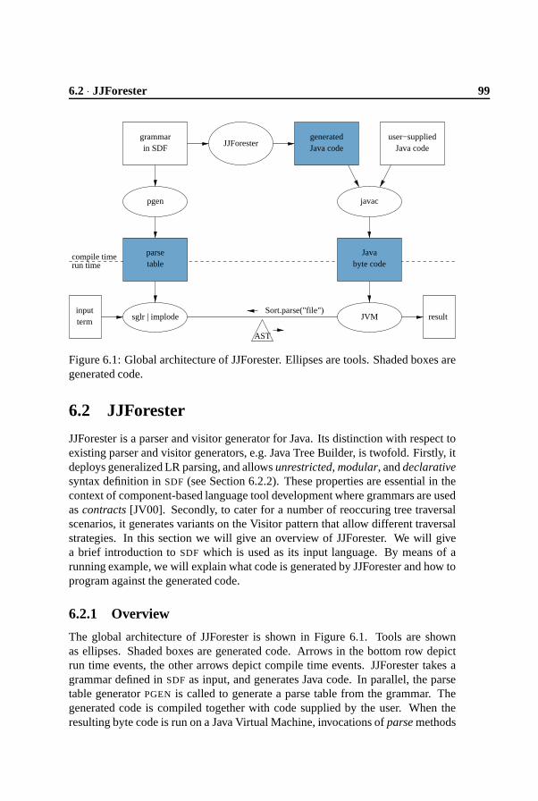
6.2 � JJForester 99
grammarin SDF
pgen javac
term
AST
input
generatedJava code
user−suppliedJava code
sglr | implodeSort.parse("file")
result
Javabyte code
JVM
parsetable
compile timerun time
JJForester
Figure 6.1: Global architecture of JJForester. Ellipses are tools. Shaded boxes aregenerated code.
6.2 JJForester
JJForester is a parser and visitor generator for Java. Its distinction with respect toexisting parser and visitor generators, e.g. Java Tree Builder, is twofold. Firstly, itdeploys generalized LR parsing, and allows unrestricted, modular, and declarativesyntax definition in SDF (see Section 6.2.2). These properties are essential in thecontext of component-based language tool development where grammars are usedas contracts [JV00]. Secondly, to cater for a number of reoccuring tree traversalscenarios, it generates variants on the Visitor pattern that allow different traversalstrategies. In this section we will give an overview of JJForester. We will givea brief introduction to SDF which is used as its input language. By means of arunning example, we will explain what code is generated by JJForester and how toprogram against the generated code.
6.2.1 Overview
The global architecture of JJForester is shown in Figure 6.1. Tools are shownas ellipses. Shaded boxes are generated code. Arrows in the bottom row depictrun time events, the other arrows depict compile time events. JJForester takes agrammar defined in SDF as input, and generates Java code. In parallel, the parsetable generator PGEN is called to generate a parse table from the grammar. Thegenerated code is compiled together with code supplied by the user. When theresulting byte code is run on a Java Virtual Machine, invocations of parse methods

100 Object-Oriented Tree Traversal with JJForester � 6
will result in calls to the parser SGLR. From a given input term, SGLR produces aparse tree as output. These parse trees are passed through the parse tree implosiontool implode to obtain abstract syntax trees.
6.2.2 SDF
The language definition that JJForester takes as input is written in SDF. In order toexplain JJForester, we will give a short introduction to SDF. A complete accountof SDF can be found in [HHKR89, Vis97b].
SDF stands for Syntax Definition Formalism, and it is just that: a formalismto define syntax. SDF allows the definition of lexical and context-free syntax inthe same formalism. SDF is a modular formalism; it allows productions to bedistributed at will over modules. For instance, mutually dependent productionscan appear in different modules, as can different productions for the same non-terminal. This implies, for instance, that a kernel language and its extensionscan be defined in different modules. Like extended BNF, SDF offers constructs todefine optional symbols and iteration of symbols, but also for separated iteration,alternatives, and more.
Figure 6.2 shows an example of an SDF grammar. This example grammargives a modular definition of a tiny lambda calculus-like language with typedlambda functions. Note that the orientation of SDF productions is reversed withrespect to BNF notation. The grammar contains two context-free non-terminals,Expr and Type, and two lexical non-terminals, Identifier and LAYOUT. The latternon-terminal is used implicitly between all symbols in context-free productions.As the example details, expressions can be variables, applications, or typed lambdaabstractions, while types can be type variables or function types.
SDF’s expressiveness allows for defining syntax concisely and naturally. SDF’smodularity facilitates reuse. SDF’s declarativeness makes it easy and retargetable.But the most important strength of SDF is that it is supported by Generalized LRParsing. Generalized parsing removes the restriction to a non-ambiguous subclassof the context-free grammars, such as the LR(k) class. This allows a maximallynatural expression of the intended syntax; no more need for ‘bending over back-wards’ to encode the intended grammar in a restricted subclass. Furthermore,generalized parsing leads to better modularity and allows ‘as-is’ syntax reuse.
As SDF removes any restriction on the class of context-free grammars, thegrammars defined with it potentially contain ambiguities. For most applications,these ambiguities need to be resolved. To this end, SDF offers a number of dis-ambiguation constructs. The example of Figure 6.2 shows four such constructs.The left and right attributes indicate associativity. The bracket attribute indicatesthat parentheses can be used to disambiguate Exprs and Types. For the lexicalnon-terminals the longest match rule is explicitly specified by means of followrestrictions. Not shown in the example is SDF’s notation for relative priorities.

6.2 � JJForester 101
� � ����� ������������ �� � �
��������� �� ���� � ��� ��������� � �������� �� ��������� ��� ������� �� �� "!�����#����� ��������� ��� �����%$ � � � ���� '& � ��� � !�"(()� ��� � �������� �� �'*��,+� � � �'-�� �����
��������� ��� �����%. � ��/ � � �� "!����� ����� �� �� ��������� / �� �"0 ��� !� � ����� � +� � ������ �� � �
��������� �� ���� � ��� ��������� � �������� �� � +� � ��� ��� �����%+�� �� �� "!+� � � � � �,+� � � � +� � ��� ��� �����%$ ��1 �� '& ���2�3�� !�����,+� � � �� �� � +� � ��� / �� �"0 ��� !� � ����� � ��� � �������� ������� �� � �
� ����� ��� � ��� ������4 $ �5�� �6�7� �8�9:; � ��� � �������� ��� ����� ��� � �� � ��� ����� �
��� � �������� ��< = 4 $ �5�� �6�7� �8�9� � ����� � . � � � � ������ �� � �
� ����� ��� � ��� ������4 (�( � ( �9> � .$�?�@�A�+��������� �� ���� �#�� � ��� ����� �
.$�?�@�A�+�B = 4 (�( � ( �9
Figure 6.2: Example SDF grammar.

102 Object-Oriented Tree Traversal with JJForester � 6
In the example grammar, each context-free production is attributed with a con-structor name, using the cons(..) attribute. Such a grammar with constructornames amounts to a simultaneous definition of concrete and abstract syntax ofthe language at hand. The implode back-end turns concrete parse trees emanatedby the parser into more concise abstract syntax trees (ASTs) for further processing.The constructor names defined in the grammar are used to build nodes in the AST.As will become apparent below, JJForester operates on these abstract syntax trees,and thus requires grammars with constructor names. A utility, called sdf-cons isavailable to automatically synthesize these attributes when absent.
SDF is supported by two tools: the parse table generator PGEN, and the scan-nerless generalized parser SGLR. These tools were originally developed as com-ponents of the ASF+SDF Meta-Environment and are now separately available asstand-alone, reusable tools.
6.2.3 Code generation
From an SDF grammar, JJForester generates the following Java code:
Class structure For each non-terminal symbol in the grammar, an abstract classis generated. For each production in the grammar, a concrete class is generated thatextends the abstract class corresponding to the result non-terminal of the produc-tion. For example, Figure 6.3 shows a UML diagram of the code that JJForestergenerates for the grammar in Figure 6.2. The relationships between the abstractclasses Expr and Type, and their concrete subclasses are known as the Compositepattern.
Lexical non-terminals and productions are treated slightly differently: for eachlexical non-terminal a class can be supplied by the user. Otherwise, this lexicalnon-terminal is replaced by the pre-defined non-terminal
/� ��� � � � ����� , for which
a single concrete class is provided by JJForester. This is the case in our example.When the input grammar, unlike our example, contains complex symbols such
as optionals or iterated symbols, additional classes are generated for them as well.The case study will illustrate this.
Parsers Also, for every non-terminal in the grammar, a parse method is gen-erated for parsing a term (plain text) and constructing a tree (object structure).The actual parsing is done externally by SGLR. The parse method implementsthe Abstract Factory design pattern; each non-terminal class has a parse methodthat returns an object of the type of one of the constructors for that non-terminal.Which object gets returned depends on the string that is parsed.
Constructor methods In the generated classes, constructor methods are gener-ated that build language-specific tree nodes from the generic tree that results from

6.2 � JJForester 103
Apply Var Lambda TVar Arrow
expr0
expr1
type0
type1Type
Visitor
visit
...
Visitable
accept_buaccept_td
Expr
Identifier
identifier0
identifier0identifier0
type1expr2
visitExprvisitApply
accept_bu(Visitor v){
expr0.accept_bu(v);
expr1.accept_bu(v);
}
visitApply(this);
Figure 6.3: The UML diagram of the code generated from the grammar in Fig-ure 6.2.
the call to the external parser.
Set and get methods In the generated concrete classes, set and get methods aregenerated to inspect and modify the fields that represent the subtrees. For example,the Apply class will have � ���
�� � � Q and ����� � � � � Q methods for its first child.
Accept methods In the generated concrete classes, several accept methods aregenerated that take a Visitor object as argument, and apply it to a tree node. Cur-rently, two iterating accept methods are generated: � ��� � � � � and � ����� � ���
,for top-down and bottom-up traversal, respectively. For the Apply class, the bottom-up accept method is shown in the Figure 6.3.
Visitor classes A Visitor class is generated which contains a visit method foreach production and each non-terminal in the grammar. Furthermore, it containsone unqualified visit method which is useful for generic refinements (see below).These visit methods are non-iterating: they make no calls to accept methods ofchildren to obtain recursion. The default behavior offered by these generated visitmethods is simply to do nothing.
Together, the Visitor class and the accept methods in the various concreteclasses implement a variant of the Visitor pattern [GHJV94], where the respon-

104 Object-Oriented Tree Traversal with JJForester � 6
sibility for iteration lies with the accept methods, not with the visit methods. Wehave chosen this variant for several reasons. First of all, it relieves the program-mer who specializes a visitor from reconstructing the iteration behavior in the visitmethods he redefines. This makes specializing visitors less involved and less error-prone. In the second place, it allows the iteration behavior (top-down or bottom-up) to be varied. In Section 6.4.3 we will comment on the possibilities of offeringeven more control over iteration behavior.
Apart from generating Java code, JJForester calls PGEN to generate a parse tablefrom its input grammar. This table is used by SGLR which is called by the gener-ated parse methods.
6.2.4 Programming against the generated code
The generated code can be used by a tool builder to construct tree traversalsthrough the following steps:
1. Refine a visitor class by redefining one or more of its visit methods. Aswill be explained below, such refinement can be done at various levels ofgenericity, and in a step-wise fashion.
2. Start a traversal with the refined visitor by feeding it to the accept method ofa tree node. Different accept methods are available to realize top-down orbottom-up traversals.
This method of programming traversals by refining (generated) visitors providesinteresting possibilities for reuse. Firstly, many traversals only need to do some-thing ‘interesting’ at a limited number of nodes. For these nodes, the programmerneeds to supply code, while for all others the behavior of the generated visitoris inherited. Secondly, different traversals often share behavior for a number ofnodes. Such common behavior can be captured in an initial refinement, which isthen further refined in diverging directions. Unfortunately, Java’s lack of multipleinheritance prohibits the converse: construction of a visitor by inheritance fromtwo others (but see Section 6.4.3 for further discussion). Thirdly, some traversalactions may be specific to nodes with a certain constructor, while other actions arethe same for all nodes of the same type (non-terminal), or even for all nodes of anytype. As the visitors generated by JJForester allow refinement at each of these lev-els of specificity, there is no need to repeat the same code for several constructorsor types. We will explain these issues through a number of small examples.
Constructor-specific refinement Figure 6.4 shows a refinement of the Visitorclass which implements a traversal that counts the number of variables occurringin a syntax tree. Both expression variables and type variables are counted.

6.2 � JJForester 105
������������������ � �� �� ����� � ������ � ������������� � ������ � ������������������ � ������� � ��������������� � ������������ � �� � �� � � �� � ������� �!�! �"
������������ � ������������ ��� �� ��� �� �� � �� � ������� �!�! �"
"
Figure 6.4: Specific refinement: a visitor for counting variables.
����������#�������� � ��� �� ����� � ������� � $����������� � ������� � ������������������� � ������� � ��������������� � ������������ � ��� � ��� �� � �� � ������� �!�! �"
"
����������#�������� � � ��� �� ����� � ������� � $����������� � ������� � ������������������� � ������� � ��������������� � ������������ � �&%�&��� � � �� � ������� �!�! �"
"
Figure 6.5: Generic refinement: visitors for counting expressions and nodes.
This refinement extends Visitor with a counter field, and redefines the visitmethods for Var and TVar such that the counter is incremented when such nodesare visited. The behavior for all other nodes is inherited from the generated Visitor:do nothing. Note that redefined methods need not restart the recursion behaviorby calling an accept method on the children of the current node. The recursion iscompletely handled by the generated accept methods.
Generic refinement The refinement in the previous example is specific for par-ticular node constructors. The visitors generated by JJForester additionally allowmore generic refinements. Figure 6.5 shows refinements of the Visitor class thatimplement a more generic expression counter and a fully generic node counter.Thus, the first visitor counts all expressions, irrespective of their constructor, andthe second visitor counts all nodes, irrespective of their type. No code duplicationis necessary.

106 Object-Oriented Tree Traversal with JJForester � 6
visitExprvisitApply...
visitVar
Set
visit
Visitor
addremove
GetVarsVisitor
vars
visitLambda
FreeVarsVisitor
...v = new FreeVarsVisitor();
...expr.accept_bu(v);
Example of usage:
} vars.add(var.getIdentifier());visitVar(Var var) {
visitLambda(Lambda lambda) { vars.remove(var.getIdentifier());}
Figure 6.6: UML diagram for user code.
Step-wise refinement Visitors can be refined in several steps. For our examplegrammar, two subsequent refinements of the Visitor class are shown in Figure 6.6.The class GetVarVisitor is a visitor for collecting all variables used in expressions.It is defined by extending the Visitor class with a field ������� initialized as the emptyset of variables, and by redefining the visit method for the Var class to insert eachvariable it encounters into this set. The GetVarVisitor is further refined into avisitor that collects free variables, by additionally redefining the visit method forthe Lambda class. This redefined method removes the variables bound by thelambda expression from the current set of variables. Finally, this second visitorcan be unleashed on a tree using the �������� ��� method. This is illustrated by anexample of usage in Figure 6.6.
Note that the visitors in Figures 6.4 and 6.5 can be refactored as refinementsof a common initial refinement, say CountVisitor, which contains only the fieldcounter.
Of course, our running example does not mean to suggest that Java would bethe ideal vehicle for implementing the lambda calculus. Our choice of examplewas motivated by simplicity and self-containedness. To compare, an implemen-tation of the lambda calculus in the ASF+SDF Meta-Environment can be foundin [DHK96]. In Section 6.3 we will move into the territory for which JJForester isintended: component-based development of program analyses and transformationsfor languages of non-trivial size.

6.2 � JJForester 107
6.2.5 Assessment of expressiveness
To evaluate the expressiveness of JJForester within the domain of language pro-cessing, we will assess which program transformation scenarios can be addressedwith it. We distinguish three main scenarios:
Analysis A value or property is distilled from a syntax tree. Type-checking is aprime example.
Translation A program is transformed into a program in a different language.Examples include generating code from a specification, and compilation.
Rephrasing A program is transformed into another program, where the sourceand target language coincide. Examples include normalization and renova-tion.
For a more elaborate taxonomy of program transformation scenarios, we referto [V
�
]. The distinction between analysis and translation is not clear-cut. Whenthe value of an analysis is highly structured, especially when it is an expression inanother language, the label ‘translation’ is also appropriate.
The traversal examples discussed above are all tree analyses with simple accu-mulation in a state. Here, ‘simple’ accumulation means that the state is a value orcollection to which values are added one at a time. This was the case both for thecounting and the collecting examples. However, some analyses require more com-plex ways of combining the results of subtree traversals than simple accumulation.An example is pretty-printing, where literals need to be inserted between pretty-printed subtrees. In the case study, a visitor for pretty-printing will demonstratethat JJForester is sufficiently expressive to address such more complex analyses.However, a high degree of reuse of the generated visit methods can currently onlybe realized for the simple analyses. In the future work section (6.4.3), we willdiscuss how such reuse could be realized by generating special visitor subclassesor classes that model updatable many-sorted folds [LVK00].
Translating transformations are also completely covered by JJForester’s ex-pressiveness. As in the case of analysis, the degree of reuse of generated visitmethods can be very low. Here, however, the cause lies in the nature of transla-tion, because it typically takes every syntactic construct into account. This is notalways the case, for instance, when the translation has the character of an analysiswith highly structured results. An example is program visualization where onlydependencies of a particular kind are shown, e.g. module structures or call graphs.
In the object-oriented setting, a distinction needs to be made between destruc-tive and non-destructive rephrasings. Destructive rephrasings are covered by JJ-Forester. However, as objects can not modify their self reference, destructive mod-ifications can only change subtrees and fields of the current node, but they cannotreplace the current node by another. Non-destructive rephrasings can be imple-

108 Object-Oriented Tree Traversal with JJForester � 6
��� ��� ��� � � � ���
� �� �
ToolBus:
� � � � � � � ���
evaldo
ack-event
value
event
Tools:
Adapters:
Figure 6.7: The Toolbus architecture. Tools are connected to the bus throughadapters. Inside the bus, several processes run in parallel. These processes com-municate with each other and the adapters according to the protocol defined in aT-script.
mented by refining a traversal that clones the input tree. A visitor for tree cloningcan be generated, as will be discussed in Section 6.4.3.
A special case of rephrasing is decoration. Here, the tree itself is traversed, butnot modified except for designated attribute fields. Decoration is useful when sev-eral traversals are sequenced that need to share information about specific nodes.JJForester does not cover decoration yet.
6.3 Case study
Now that we have explained the workings of JJForester, we will show how itis used to build a program analyzer for an actual language. In particular, thiscase study concerns a static analyzer for the ToolBus [BK98] script language. InSection 6.3.1 we describe the situation from which a need for a static analyzeremerged. In Section 6.3.2 the language to be analyzed is briefly explained. Finally,Section 6.3.3 describes in detail what code needs to be supplied to implement theanalyzer.
6.3.1 The Problem
The ToolBus is a coordination language which implements the idea of a softwarebus. It allows applications (or tools) to be “plugged into” a bus, and to communi-cate with each other over that bus. Figure 6.7 gives a schematic overview of theToolBus. The protocol used for communication between the applications is notfixed, but is programmed through a ToolBus script, or T-script.
A T-script defines one or more processes that run inside the ToolBus in parallel.These processes can communicate with each other, either via synchronous point-

6.3 � Case study 109
to-point communication, or via asynchronous broadcast communication. The pro-cesses can direct and activate external components via adapters, small pieces ofsoftware that translate the ToolBus’s remote procedure calls into calls that are na-tive to the particular software component that needs to be activated. Adapters canbe compiled into components, but off-the-shelf components can be used, too, aslong as they possess some kind of external interface.
Communication between processes inside the ToolBus does not occur overnamed channels, but through pattern matching on terms. Communication betweenprocesses occurs when a term sent by one matches the term that is expected byanother. This will be explained in more detail in the next section. This style ofcommunication is powerful, flexible and convenient, but tends to make it hard topinpoint errors in T-scripts. To support the T-script developer, the ToolBus runtimesystem provides an interactive visualizer, which shows the communications takingplace in a running ToolBus. Though effective, this debugging process is tediousand slow, especially when debugging systems with a large number of processes.
To complement the runtime visualizer, a static analysis of T-scripts is neededto support the T-script developer. Static analysis can show that some processescan never communicate with each other, that messages that are sent can neverbe received (or vice versa), or that two processes that should not communicatewith each other may do so anyway. Using JJForester, such a static analyzer isconstructed in Section 6.3.3.
6.3.2 T-scripts explained
T-scripts are based on ACP (Algebra of Communicating Processes) [BV95]. Theydefine communication protocols in terms of actions, and operations on these ac-tions. We will be mainly concerned with the communication actions, which wewill describe below. Apart from these, there are assignment actions, conditionalactions and basic arithmetic actions. The action operators include sequential com-position ( � � ), non-deterministic choice ( � �
), parallel composition ( � ), andrepetition ( ; � ). The full specification of the ToolBus script language can befound in [BK94].
The T-script language offers actions for communication between processes andtools, and for synchronous and asynchronous communication between processes.For the purposes of this paper we will limit ourselves to the most commonly usedsynchronous actions. These are � � �
� � � ��� ��� and ����� � � � ��� ��� for sending andreceiving messages, respectively. These actions are parameterized with arbitrarydata
�, represented as ATerms [BJKO00]. A successful synchronous communica-
tion occurs when a term that is sent matches a term that is received. For instance,the closed term ��� �
� � � ��� � � ���
can match the closed term ����� � � � ��� � � ���
orthe open term ����� � � � ��� � � ���� . At successful communication, variables in thedata of the receiving process are instantiated according to the match.

110 Object-Oriented Tree Traversal with JJForester � 6
S���"� ������H,�'�W�SX�������$�� � �%#�$�%#6Y���� �L�W���&E6<�� �$�������$��E6 ����9�9E����� �L�W���&E6<"�#9E���#�(�L�W���&E6 ����S�"���$)6 � 9�9
9��(�����$����#�(�����$
S���"� ������!��S�������$�"��R�������$13 � �%#�$)D � � �%#�$)D
,���B�W���#�$ � �%#�$)D ��W�"�'�#�$ � �%#�$�%#6Y���� �L�W���&E6 ������'�����$)6 ��� D73���9�9:�,���B�W���#�$ � \��V���#�(�L�W���&E6 �� %A���(�'����E6 ,���B�W���#�$)D73�9�9:����� �L�W���&E6 ������'���$)6 ����9�9:���W�"�'�#�$ � \1�%'���6 ,���B�W���#�$)D � 9:���#�(�L�W���&E6 ����W��$)67��W�"�'�#�$�9�9
9��(�����$����#�(�����$S���"� �������3�'���$�"�W����R�������$3 � �%#�$)D � � �%#�$�%#3 � \�S���"� �������L���(K�� � \R��+K��%#�(�L�W���&E6 S�����S���BE6 �KD73�9�9:����� �L�W���&E6 "���BE6<3�9�9:��%#�(�L�W���&E67$�'���#�L�"�#9:�
S�����#�$�C)6� 3�'���$�"�W�������(!'���%#�&�S�'�W�S� �#���D3�9:�
���� �L�W���&E6?��$�"�S9E����� �L�W���&E6? %A���#�&��:6 ����9�9:�S�����#�$�C)6� 3�'���$�"�W�������(I&�"�$�����(1 %A���#�&��� �#��D3)D �9
��#�(�����$
S���"� ������������� �$���$���"�#R�������$� � ��#�$)D 3 � �%#�$�%#6Y���� �L�W���&E6 S�����S���BE6 ��� D73���9�9:���#�(�L�W���&E6 ������'�����$)6 �KD73�9�9��� ���� �L�W���&E6 �� %A���(�'����E6 ��� D73���9�9:���#�(�L�W���&E6<�� �$�������$��E6 �9�9:���#�(�L�W���&E6<"���BE673�9�9��� ���� �L�W���&E6 $�'���#�L�"�#9E���#�(�L�W���&E6<"�#9��� ���� �L�W���&E6 ����S�"���$)6 ����9�9:���#�(�L�W���&E6 ��$�"�S9:���#�(�L�W���&E6 ������'���$)6 � 9�9��� ���� �L�W���&E6 ����W��$)6 ����9�9:���#�(�L�W���&E6 %A���#�&��:6 � 9�9
9��(�����$����#�(�����$
$�"�"�����'�� 6������� �$���$���"�#�D ,�'�W�S�D3�'���$�"�W����)D73�'��$�"�W����)D<��S�������$�"��9
Figure 6.8: The T-script for the gas station with control process.
To illustrate, a small example T-script is shown in Figure 6.8. This exam-ple contains only processes. In a more realistic situation these processes wouldcommunicate with external tools, for instance to get the input of the initial value,and to actually activate the gas pump. The script’s last statement is a mandatory��� � � ��� � ����� � statement, which declares that upon startup the processes GasSta-tion, Pump, Customer and Operator are all started in parallel. The first action ofall processes, apart from Customer, is a ����� � � � � action. This means that thoseprocesses will block until an appropriate communication is received. The Cus-tomer process starts by doing two assignment statements. � ������� � � � � � (a built-invariable that contains the identifier of the current process) is assigned to
�, and 10
to�
. The first communication action performed by Customer is a � � �� � � � of the
term � � ��� �� � ��� ��� . This term is received by the GasStation process, which in turnsends the term ��� � � � � � � ��� ��� message. This is received by Operator, and so on.
The script writer can use the mechanism of communication through term match-ing to specify that any one of a number of processes should receive a message,depending on the state they are in, and the sending process does not need to knowthis. It just sends out a term into the ToolBus, and anyone of the accepting pro-

6.3 � Case study 111
toString
visitIdTermvisitIterStarSepTerm_visitOptVarvisitStringTermvisitVnameVar
send receive
currProcess
processNametheStack
...
visitProcDefvisitProcDefArgs
Stack
pushpop
Set
addremove
String
...
...
visit
Visitor
visitFunTermvisitProcDef
...
SendReceiveAction
match
visitFunTerm
TermToStringVisitor SendReceiveDB
addSendActionprintMatchTable
addReceiveAction
storeMatchTable
SendReceiveVisitor
visitFunTerm srdb
Figure 6.9: UML diagram of the ToolBus analyzer.
cesses can “pick it up”. Unfortunately, when incorrect or too general terms arespecified, communication will not occur as expected, and the exact cause will bedifficult to trace. The static analyzer developed in the next section is intended tosolve this problem.
6.3.3 Analysis using JJForester
We will first sketch the outlines of the static analysis algorithm that we imple-mented. It consists of two phases: collection and matching. In the collectionphase, all send and receive actions in the T-script are collected into a (internal,non-persistent) database. In the matching phase, the send and receive actions inthe database are matched to obtain a table of potential matching events, whichcan either be stored in a file, or in an external, persistent relational database. Tovisualize this table, we use the back-end tools of a documentation generator wedeveloped earlier (DocGen [DK99a]).
We used JJForester to implement the parsing of T-scripts and the representationand traversal of T-script parse trees. To this end, we ran JJForester on the grammarof the ToolBus2 which contains 35 non-terminals and 80 productions (both lexi-cal and context-free). From this grammar, JJForester generated 23 non-terminalclasses, 64 constructor classes, and 1 visitor class, amounting to a total of 4221lines of Java code.
We will now explain in detail how we programmed the two phases of the anal-ysis. Figure 6.9 shows a UML diagram of the implementation.
2This SDF grammar can be downloaded from the GrammarBase, at http://www.program-transformation.org/gb.

112 Object-Oriented Tree Traversal with JJForester � 6
� � ��������� � � �����������&���� �� � ���&��� � � � ���&�� � ��� � � �� � � � ���&��� � ��� ��� � � ���&��� � � � ��� � ��� � �� � � � � � � � "� �� � ���&��� � � � ���&�� � ��� � � � � � �� � �&�� ��� "�� � � � � ��� � � � ������� � ��� ��� � � ���&��� � � � ��� � ��� � �� � � � � � ���� � � "
Figure 6.10: The syntax of process definitions.
�����&����� � � ������������ � � � � � � �� � � � � � ��� � ��� ���&� � � � �� �� � � � ���&����� ��� � ��������� � �������� ��������� � ��� � �� � � ��� �� ����� � �"
�����&����� � � ������������ � � � � � � ���� �� � � � � � �������� � ��� ����� � � � �� �� � � � ���&����� ��� � ��������� � �������� ��������� � ��� � �� � � ��� �� ����� � �"
Figure 6.11: Specialized visit methods to extract process definition names.
The collection phase
We implemented the collection phase as a top-down traversal of the syntax treewith a visitor called SendReceiveVisitor. This refinement of the Visitor class hastwo kinds of state: a database for storing send and receive actions, and a field thatindicates the name of the process currently being analyzed. Whenever a term withoutermost function symbol snd-msg or rec-msg is encountered, the visitor will adda corresponding action to the database, tagged with the current process name. Thecurrent process name is set whenever a process definition is encountered duringtraversal. Since sends and receives occur only below process definition in the parsetree, the top-down traversal strategy guarantees that the current process name fieldis always correctly set when it is needed to tag an action.
To discover which visit methods need to be redefined in the SendReceiveVis-itor, the ToolBus grammar needs to be inspected. To extract process definitionnames, we need to know which syntactic constructs are used to declare thesenames. The two relevant productions are shown in Figure 6.10. So, in order to ex-tract process names, we need to redefine � � � ��� � ����� � � �
and � � � � � � ����� � � � - � � �
in our specialized SendReceiveVisitor. These redefinitions are shown in Figure 6.11.Whenever the built-in iterator comes across a node in the tree of type � ����� � � �
,it will call our specialized � � � � � � � ��� � � �
with that � ������ � �
as argument. Fromthe SDF definition in Figure 6.10 we learn that a � ����� � � �
has two children: aProcessName and a ProcessExpr. Since ProcessName is a lexical non-terminal,and we chose to have JJForester identify all lexical non-terminals with a singletype
/� ��� � �
� � ��� , the Java class � ����� � � �has a field of type
/� ��� � �
� ����� andone of type
� ������� � ��� � � . Through the � ��� / � ��� � � � � ��� Q � � method we get the
actual process name which gets converted to a String so it can be assigned to� � � � � ������� � � .

6.3 � Case study 113
� � �������� � � ���������������� ���� � ��� � �� ��� � � � � ������ � � �� � � "� �� ��� � ��� � �� ��� � � � � �&�� � � "� �� � � � ��� � ��� � �� ��� � � � � � ��� � �� � � "� ��� � �� ��� � � � ��� � � � � �������&�� � � � � � " � ��� � � � ��� � � � � ��� � � � � � " � � � � �� � � ����� � � � ��� � � � ��� � � � � � ��� � �� � � � "� � �� � ���� "�� ��� � � � � ��������� � � � � ��� � � �&�� � � "� � � ��� � � � ��� � � � � ��� � � � � � � "
Figure 6.12: Syntax of relevant ToolBus terms.
������������ � ������������ � �� � � � � ��� � � � ��� � � �� ����� � �&���&����� ���&� � � ������� � �����&���� ����� � �&��������� ����� � � ���� � � � ���&�� � ��� � ������ � � � ������ � ���� �� � ��� � ������ ��������� � ��� � �� � ��������� ��� � � ��� � � ��� � ��� ��� ��� ���� � ����� � ����� ����� � � ������� � � � �" ������� � � ��� � ������ ��������� � ��� � �� � ��������� ��� � ���� � � � � � ��� ��� ��� ���� � ����� � �&���&����� ���&� � � ������� � � � �"
"
Figure 6.13: The visit method for send and receive messages.
Now that we have taken care of extracting process names, we need to ad-dress the collection of communication actions. The ToolBus grammar allows forarbitrary terms (‘Atoms’ in the grammar) as actions. Their syntax is shown inFigure 6.12.
Thus, send and receive actions are not distinct syntactical constructs, but theyare functional terms (
� � � � ��� � s) where the/� child has value � � �
� � � � or ������ � � � .
Consequently, we need to redefine the � � � � � & � � � ��� � method such that it inspectsthe value of its first child to decide if and how to collect a communication action.Figure 6.13 shows the redefined method.
The visit method starts by constructing a new� ��� � � ������� ��� - � � ����� . This is
an object that contains the term that is being communicated and the process thatsends or receives it. The process name is available in the
� ��� � � ������������� � � � � ���
in the field � � � � � � ����� � � , because it is put there by the � � � � � � ����� � � �methods
we just described. The term that is being communicated can be selected fromthe
� � � � ��� � we are currently visiting. From the SDF grammar in Figure 6.12it follows that the term is the second child of a
� � � � ��� � , and that it is of type� ��� � � � � � . Therefore, the method � ��� � ��� � ��� � � � will return it.The newly constructed action is added to the database as a send action, a re-
ceive action, or not at all, depending on the first child of the� � � � ��� � . This child
is of lexical type/� , and thus converted to an
/� ��� � �
� ����� type in the generated

114 Object-Oriented Tree Traversal with JJForester � 6
�������������&������ � � ��� � ����� � �� ������ ��� �� ���� � ���� � ��� � �� ���� � ����������� � �$�� �� �� ������� � ������� ���� � � � �� ���� &����������� � �� �� ����� � ���� �������� ���� ���� ��� � ���� � �� ����� � �&���&����� � ������ � �� ��������� � � �&��� � ����� � �&���&����� � ������� � �� ����&� � �� ������ � ����������������� �� ��������� � � � ��� � � ����&���&� � ������������ ��������� � � �� ����� � � � ���� � ��� � ������ � ������ � ���� � ������ ���������������"
Figure 6.14: The main() method of the ToolBus analyzer.
Java classes. The/� ��� � � � ����� class contains an � � � � � � � � � ��� � � method, so we
use string comparison to determine whether the current� � � � ��� � has “snd-msg”
or “rec-msg” as its function symbol.Now that we have built the specialized visitor to perform the collection, we
still need to activate it. Before we can activate it, we need to have parsed a T-script, and built a class structure out of the parse tree for the visitor to operate on.This is all done in the � ��� �
�method of the analyzer, as shown in Figure 6.14.
The main method shows how we use the generated parse method for� � � � � � � to
build a tree of objects. Tscript.parse() takes a filename as an argument and tries toparse that file as a Tscript. If it fails it throws a ParseException and displays thelocation of the parse error. If it succeeds it returns a
� � � � � � � . We then construct anew
� ��� � � ������������� � � � � ��� as described in the previous section. The� � � � � � � is
subsequently told to accept this visitor, and, as described in Section 6.2.4 iteratesover all the nodes in the tree and calls the specific visit methods for each node.When the iterator has visited all nodes, the
� ��� � � ������� ����� � � ������� contains a filled� ��� � � ������� ��� � � . The results in this database object can then be processed further,in the matching phase. In our case we call the method ����� � � � � � � % � � � � � � � � �which is explained below.
The matching phase
In the matching phase, the send and receive actions collected in the� ��� � � ������� ��� � �
are matched to construct a table of potential communication events, which is thenprinted to file or stored in a relational database. We will not discuss the matchingitself in great detail, because it is not implemented with a visitor. A visitor im-plementation would be possible, but clumsy, since two trees need to be traversedsimultaneously. Instead it is implemented with nested iteration over the sets ofsend and receive actions in the database, and simple case discrimination on terms.The result of matching is a table where each row contains the process names anddata of a matching send and receive action.
We focus on an aspect of the matching phase where a visitor does play a role.When writing the match table to file, the terms (data) it contains need to be pretty-printed, i.e. to be converted to
� � � � � � . We implemented this pretty-printer with a
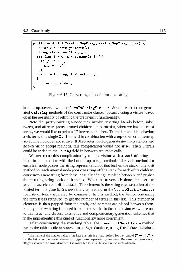
6.3 � Case study 115
������������ � ������������ ��� � �&�� � ��� � � � � ����� � �&�� � ��� � �� � �$���� � � � �� �&��� � ���#��� � � � ���� � �� � � �� �� �� �� �������� � �&��� � �� ������ �� �� � ��������� � � � � ��� ������� �� � ��!�! � �� � ��� � � � ����� !�� � ���
�"���� �!�� � �� ������ � ���&� � ������� � � � � �� �"
���&� � �&����� � ��� �� ���� � �"
Figure 6.15: Converting a list of terms to a string.
bottom-up traversal with the� ��� � � � � � � � � � � � � � ����� . We chose not to use gener-
ated ��� � � � ��� � methods of the constructor classes, because using a visitor leavesopen the possibility of refining the pretty-print functionality.
Note that pretty-printing a node may involve inserting literals before, inbe-tween, and after its pretty-printed children. In particular, when we have a list ofterms, we would like to print a “,” between children. To implement this behavior,a visitor with a single
� � � ��� � field in combination with a top-down or bottom-upaccept method does not suffice. If JJForester would generate iterating visitors andnon-iterating accept methods, this complication would not arise. Then, literalscould be added to the
� � � ��� � field in between recursive calls.We overcome this complication by using a visitor with a stack of strings as
field, in combination with the bottom-up accept method. The visit method foreach leaf node pushes the string representation of that leaf on the stack. The visitmethod for each internal node pops one string off the stack for each of its children,constructs a new string from these, possibly adding literals in between, and pushesthe resulting string back on the stack. When the traversal is done, the user canpop the last element off the stack. This element is the string representation of thevisited term. Figure 6.15 shows the visit method in the
� ��� � � � � � � � � � � � � � � ���
for lists of terms separated by commas3. In this method, the Vector containingthe term list is retrieved, to get the number of terms in this list. This number ofelements is then popped from the stack, and commas are placed between them.Finally the new string is placed back on the stack. In the conclusion we will returnto this issue, and discuss alternative and complementary generation schemes thatmake implementing this kind of functionality more convenient.
After constructing the matching table, the ����� � � � � � � % � � � � � � � methodwrites the table to file or stores it in an SQL database, using JDBC (Java Database
3The name of the method reflects the fact that this is a visit method for the symbol� + �� � ��&%� ��� ,
i.e. the list of zero or more elements of type Term, separated by commas. Because the comma is anillegal character in a Java identifier, it is converted to an underscore in the method name.

116 Object-Oriented Tree Traversal with JJForester � 6
Sender ReceiverPump report(D) GasStation report(D?)GasStation change(D) Customer change(D?)Customer prepay(D,C) GasStation prepay(D?,C?)GasStation okay(C) Customer okay(C)Operator remit(Amount) GasStation remit(D?)GasStation result(D) Operator result(D?)GasStation activate(D) Pump activate(D?)GasStation stop Customer stopCustomer turn-on GasStation turn-onOperator schedule(Payment,C) GasStation schedule(D?,C?)GasStation request(D,C) Operator request(D?,C?)GasStation on Pump on
Pump
GasStation
report(D?) activate(D?) on
Operator
result(D?) request(D?,C?)
Customer
change(D?) okay(C) stopschedule(D?,C?) remit(D?) prepay(D?,C?) turn-on
Figure 6.16: The analysis results for the input file from Figure 6.8.
Connectivity). We used a visualization back-end of the documentation generatorDocGen to query the database and generate a communication graph. The result ofthe full analysis of the T-script in Figure 6.8 is shown in Figure 6.16.
Evaluation of the case study
We conducted the ToolBus case study to learn about feasibility, productivity, per-formance, and connectivity issues surrounding JJForester. Below we briefly dis-cuss our preliminary conclusions. Apart from the case study reported here, weconducted a case study where an existing Perl component in the documentationgenerator DocGen was re-implemented in Java, using JJForester. This case studyalso corroborates our findings.
Feasibility At first glance, the object-oriented programming paradigm may seemto be ill-suited for language processing applications. Terms, pattern-matching,many-sorted signatures are typically useful for language processing, but are notnative to an object-oriented language like Java. More generally, the reference se-mantics of objects seems to clash with the value semantics of terms in a language.Thus, in spite of Java’s many advantages with respect to e.g. portability, maintain-ability, reuse, its usefulness in language processing is not evident.

6.3 � Case study 117
The case study, as well as the techniques for coping with traversal scenariosoutlined in Section 6.2, demonstrate that object-oriented programming can be ap-plied usefully to language processing problems. In fact, the support offered byJJForester makes object-oriented language processing not only feasible, but eveneasy.
Productivity Recall that the Java code generated by JJForester from the ToolBusgrammar amounts to 4221 lines of code. By contrast, the user code we developedto program the T-script analyzer consists of 323 lines. Thus, 93% of the applicationwas generated, while 7% is hand-written.
These figures indicate that the potential for increased development productiv-ity is considerable when using JJForester. Of course, actual productivity gainsare highly dependable on which program transformation scenarios need to be ad-dressed (see Section 6.2.5). The productivity gain is largly attributable to the sup-port for generic traversals.
Components and connectivity Apart from reuse of generated code, the casestudy demonstrates reuse of standard Java libraries and of external (non-Java)tools. Examples of such tools are PGEN, SGLR and implode, an SQL database, andthe visualization back-end of DocGen. Externally, the syntax trees that JJForesteroperates upon are represented in the common exchange format ATerms. This ex-change format was developed in the context of the ASF+SDF Meta-Environment,but has been used in numerous other contexts as well. In [JV00] we advocated theuse of grammars as tree type definitions that fix the interface between languagetools. JJForester implements these ideas, and can interact smoothly with tools thatdo the same. The transformation tool bundle XT [JVV00] contains a variety ofsuch tools.
Performance To get a first indication of the time and space performance of ap-plications developed with JJForester, we have applied our T-script analyzer to ascript of 2479 lines. This script contains about 40 process definitions, and 700 sendand receive actions. We used a machine with Mobile Pentium processor, 64Mb ofmemory, running at 266Mhz. The memory consumption of this experiment didnot exceed 6Mb. The runtime was 69 seconds, of which 9 seconds parsing, 55seconds implosion, and 5 seconds to analyze the syntax tree. A safe conclusionseems to be that the Java code performs acceptably, while the implosion tool needsoptimization. Needless to say, larger applications and larger code bases are neededfor a good assessment.

118 Object-Oriented Tree Traversal with JJForester � 6
6.4 Concluding remarks
6.4.1 Contributions
In this paper we set out to combine SDF support of the ASF+SDF Meta-Environmentwith the general-purpose object-oriented programming language Java. To this endwe designed and implemented JJForester, a parser and visitor generator for Javathat takes SDF grammars as input. To support generic traversals, JJForester gener-ates non-iterating visitors and iterating accept methods. We discussed techniquesfor programming against the generated code, and we demonstrated these in detailin a case study. We have assessed the expressivity of our approach in terms of theprogram-transformation scenarios that can be addressed with it. Based on the casestudy, we evaluated the approach with respect to productivity, and performanceissues.
6.4.2 Related Work
A number of parser generators, “tree builders”, and visitor generators exist forJava. JavaCC is an LL parser generator by Metamata/Sun Microsystems. Its inputformat is not modular, it allows Java code in semantic actions, and separates pars-ing from lexical scanning. JJTree is a preprocessor for JavaCC that inserts parsetree building actions at various places in the JavaCC source. The Java Tree Builder(JTB) is another front-end for JavaCC for tree building and visitor generation. JTBgenerates two iterating (bottom-up) visitors, one with and one without an extra ar-gument in the visit methods to pass objects down the tree. A version of JTB forGJ (Generic Java) exists which takes advantages of type parameters to preventtype casts. Demeter/Java is an implementation of adaptive programming [PXL95]for Java. It extends the Java language with a little (or domain-specific) languageto specify traversal strategies, visitor methods, and class diagrams. Again, theunderlying parser generator is JavaCC. JJForester’s main improvement with re-spect to these approaches is the support of generalized LR parsing. Concerningtraversals, JJForester is different from JJTree and JTB, because it generates iterat-ing accept methods rather than iterating visitors. JJForester is less ambitious andmore lightweight than Demeter/Java, which is a programming system rather thana code-generator.
ASDL (Abstract Syntax Definition Language [WAKS97]) comes with a visitorgenerator for Java (and other languages). It generates non-iterating visitors andnon-iterating accept methods. Thus, traversals are not supported. ASDL doesnot incorporate parsing or parser generation; it only addresses issues of abstractsyntax.
In other programming paradigms, work has been done on incorporating sup-port for SDF and traversals. Previously, we have combined the SDF support of theASF+SDF Meta-Environment with the functional programming language Haskell [KLV00].

6.4 � Concluding remarks 119
In this approach, traversal of syntax trees is supported with updatable, many-sortedfolds and fold combinators [LVK00]. Recently, support for generic traversals hasbeen added to the ASF interpreter. These traversals allow concise specificationof many-sorted analyses and rephrasing transformations. Stepwise refinement orgeneric refinement of such traversals is not supported. Stratego [VBT99] is a lan-guage for term rewriting with strategies. It offers a suite of primitives that allowprogramming of (as yet untyped) generic traversals. Stratego natively supportsATerms. It is used extensively in combination with the SDF components of theASF+SDF Meta-Environment.
6.4.3 Future Work
Concrete syntax and subtree sharing Currently, JJForester only supports pro-cessing of abstract syntax trees. Though the parser SGLR emits full concrete parsetrees, these are imploded before being consumed by JJForester. For many programtransformation problems it is desirable, if not essential, to process concrete syntaxtrees. A prime example is software renovation, which requires preservation of lay-out and comments in the source code. The ASF+SDF Meta-Environment supportsprocessing of concrete syntax trees. In order to broaden JJForester’s applicability,and to ensure its smooth interoperation with components developed in ASF, weconsider adding concrete syntax support.
When concrete syntax is supported, the trees to be processed are significantlylarger. To cope with such trees, the ASF+SDF Meta-Environment uses the ATermlibrary which implements maximal subtree sharing. As a Java implementationof the ATerm library is available, subtree sharing support could be added to JJ-Forester. We would like to investigate the repercusions of such a change to treerepresentation for the expressiveness and performance of JJForester.
Decoration and aspect-orientation Adding a Decoration field to all generatedclasses would make it possible to store intermediate results inside the object struc-ture inbetween visits. This way, a first visitor could calculate some data and storeit in thee object structure, and then a second visitor could “harvest” these data andperform some additional calculation on them.
More generally, we would like to experiment with aspect-oriented techniques[KL
�
97] to customize or adapt generated code. Adding decoration fields to gen-erated classes would be an instance of such customization.
Object-oriented folds and strategies As pointed out in Sections 6.2.5 and 6.3.3,not all transformation scenarios are elegantly expressible with our generated vis-itors. A possible remedy would be to generate additional instances of the visitorclass for specific purposes. In particular, visitors for unparsing, pretty-printing,and equality checking could be generated. Also, the generated visitors could offer

120 Object-Oriented Tree Traversal with JJForester � 6
additional refinable methods, such as � � � � � � � � ��� � and � � � � � - � � ��� . Anotheroption is to generate iterating visitors as well as non-iterating ones. Several ofthese possibilities have been explored in the context of the related systems dis-cussed above. Instead of the visitor class, an object-oriented variation on updat-able many-sorted folds could be generated. The main difference with the visitorpattern would be that the arguments of visit functions are not (only) the currentnode, but its children, and only a bottom-up accept method would be available.More experience is needed to establish which of these options would best suit ourapplication domains.
The Visitor pattern, both in the variant offered by JJForester, where iteration isin the accept methods, and in the more common variant where iteration is in thevisit methods, is severely limited in the amount of control that the user has overtraversal behaviour. Generation of classes and methods to support folding wouldenrich the traversal repertoire, but only in a limited way. To obtain full controlover traversal behaviour, we intend to transpose concepts from strategic rewriting,as embodied by Stratego and the rewriting calculus [CK99], to the object-orientedsetting. In a nutshell the approach comes down to the following. Instead of doingiteration either in visit or accept methods, iteration would be done in neither. In-stead, a small set of traversal combinators can be generated for each grammar, inthe form of well-chosen refinements of the Visitor class. These traversal combina-tors would be direct translations of the strategy combinators in the aforementionedrewriting languages. For instance, the sequence combinator �� � can be modelledas a visitor with two fields of type Visitor, and visit methods that apply these twoargument visitors one after another. Using such combinators, the programmer canprogram generic traversal strategies instead of merely selecting one from a fixedset. As an additional benefit, such combinators would remove the need for multipleinheritance for combining visitors. We intend to broaden JJForester’s generationscheme to generate traversal combinators, and to explore programming techniqueswith these.
Availability JJForester is free software, distributed as open source under theGPL license. It can be downloaded from http://www.jjforester.org.
Acknowledgements We would like to thank Arie van Deursen for his earlierwork on building visitors for structures derived from SDF, and the discussionsabout this work. Ralf Lammel and Paul Klint provided us with useful commentson a draft version.

Chapter 7
Legacy to the Extreme
In this chapter the relation of the techniques developed earlier inthis thesis with a software development process called “Extreme Pro-gramming” is examined. Extreme programming is billed as a devel-opment method, i.e., a method to develop new software systems. Thischapter examines the feasibility of applying this method to the main-tenance of legacy systems.1
7.1 Introduction
In this paper, we explore the relationship between legacy systems and extremeprogramming. We explain how the use of (reverse engineering) tools can help toreduce the cost of change in a legacy setting, and illustrate the use of these tools.Subsequently, we discuss how and which XP practices can be incorporated intothe maintenance of legacy software systems, and we analyze how and why thepositive effects for regular and legacy XP projects are different. We conclude withan episode in which a pair of XP programmers face the task of changing hostileCobol code (examples included), and are able to do so thanks to their tools andbag of XP practices.
One of the key elements of extreme programming (XP) is design for today,so that the system is equally prepared to go any direction tomorrow. As Beckargues, one of the reasons XP gets away with this minimalist approach becauseit exploits the advances in software engineering technology, such as relationaldatabases, modular programming, and information hiding, which all help to re-duce the cost of changing software [Bec99]. The result of this is that the software
1This chapter was published earlier as: A. van Deursen, T. Kuipers, and L. Moonen. Legacy to theextreme. In M. Marchesi and G. Succi, editors, eXtreme Programming Examined. Addison-Wesley,Reading, Massachusetts, May 2001.

122 Legacy to the Extreme � 7
developer does not need to worry about future changes: the change-cost curve isno longer exponential, but linear. Making changes easily is further supported byXP in various ways:
� Releases are small and frequent, keeping changes small as well;
� The code gets refactored every release, keeping it concise and adaptable;
� Testing is at the heart of XP, ensuring that refactored code behaves as itshould.
The assumption that the system under construction is easily modifiable rulesout an overwhelming amount of existing software: the so-called legacy systems,which by definition resist change [BS95]. Such systems are written using technol-ogy such as Cobol, IMS or PL/I, which does not permit easy modification. (Asan example, we have encountered a 130,000 lines of code Cobol system contain-ing 13,000 go-to statements.) Moreover, their internal structure has degraded afterrepeated maintenance, resulting in systems consisting of duplicated (but slightlymodified) code, dead code, support for obsolete features, and so on. The extremesolution that comes to mind is to throw such systems away — unfortunately, ittakes time to construct the new system, during which the legacy system will haveto be maintained and modified.
Now what if an extreme programmer were to maintain such a legacy system?(Which probably means he was either forced to do so or seduced by an extremesalary). Should he drop all XP practices because the legacy system resists change?We will try to demonstrate in this paper why he should not. He could write testcases for the programs he has to modify, run the tests before modification, refactorhis code after modification, argue for small releases, ask for end-user stories, andso on, practices that are all at the heart of XP.
7.2 Tools Make It Possible
Refactoring legacy source code is, in principle, no different from refactoring “reg-ular” source code. Refactoring is done to improve the code, whether improvingcan mean many things. Modifications can be made to improve adaptability, read-ability, testability, or efficiency.
There are some things particular to refactoring legacy code. In order to makesure that a refactoring does not alter the functionality of the system, unit tests arerun before and after the refactoring. In a legacy setting there are no unit testsbeforehand, so they need to be written specifically for the refactoring.
Refactoring also requires the developers to have a great deal of detailed knowl-edge about the system. A good example of this is the modification of the transac-tion interface as described by [Bec99, Chapter 5]. This knowledge can come from

7.2 � Tools Make It Possible 123
someone who knows the system intimately, or can be provided by tools that allowa developer to get to these details quickly and accurately.
Modern development systems in general provide those details. They provideall sorts of development-time and run-time information which allows hunches tobe verified within seconds. Most legacy maintenance (and development) is doneon a mainframe however, and the mix of JCL, Cobol and others has to be controlledwithout advanced development tools. Usually, even basic search tools such as grepare not available. The development team manages to get by, only because part ofthe team has been working on the system for years (ever since that mainframe wascarried into the building). New team members are introduced to the system on aneed-to-know basis.
More and more often, these systems get “outsourced”, (the developmentteam is sold off to another company, and the maintenance of the system is thenhired from this new company). After such an outsourcing the original develop-ment/maintenance team usually falls apart, and knowledge of the system is lost.And it is still running on that same mainframe, without grep.
Consequently, maintenance on these systems will be of the break-down variety.Only when things get really bad, someone will don his survival suit and ventureinside the source code of the system, hoping to fix the worst of the problems. Thisis the state most administrative systems in the world are in [BL76].
7.2.1 The Legacy Maintenance Toolbox
We have been developing a toolset over the last few years which integrates a num-ber of results from the areas of reverse engineering and compiler construction.The toolset is the Legacy Maintenance Toolbox (LMT). It consists of a numberof loosely coupled components. One of the components is DocGen [DK99a], (socalled because of its basic ability to generate documentation from the source code).DocGen generates interactive, hyperlinked documentation about legacy systems.The documentation is interactive in that it combines various views of the system,and different hierarchies, and combines those with a code browser (see Figure 7.1for an example session). DocGen shows call graphs for the whole system, but alsoper program. It shows database access, and can visualize data dependencies be-tween different programs. Here, we try to provide the programmer with as muchinformation as we can possibly get from the source. (One of the problems is thatthe source may be written in a vendor specific dialect of a more conventional lan-guage, of which no definition is published.)
We augment the DocGen code browsing facility with TypeExplorer [DM99], asystem which infers types for variables in an untyped language (typically Cobol),and lets the programmer browse the code using those types. TypeExplorer canbe used, for instance, to aid in impact analysis sessions. When the requirementsof a financial system change from “make sure all amounts are British Pounds” to

124 Legacy to the Extreme � 7
Figure 7.1: An example DocGen session.

7.2 � Tools Make It Possible 125
“make sure all amounts are Euros” this will inevitably have an impact on all data(both variables in the code, and data in databases) which are of type “amount”.Because TypeExplorer can come up with a list of all variables that are in the sametype equivalence class, the programmer only has to identify a single variable whichdeals with amounts to identify all variables in the same type equivalence class (andtherefore also dealing with amounts).
The combination of DocGen and TypeExplorer proves to be a powerful toolfor gaining insight into the details of a system. DocGen and TypeExplorer gettheir information from a repository, which is filled by a combination of parsing (ifwe have a grammar for the legacy system’s language) and lexical analysis. Thisrepository can also be queried directly, using standard SQL queries.
One of the key properties of LMT is that it is open: external tools can be easilyintegrated. An example tool is CloneDr, from Semantic Designs, which detects(near) clones (or “copy-paste code”) in sources, and removes them (by replacingthem with a single procedure and a number of calls to that procedure, for instance)[BYM
�
98]. Code clone removal can be seen as an automated refactoring opera-tion that adheres to the XP principle of say it once and only once. Apart from theobvious benefit of reducing the amount of code to be understood, a less expectedbenefit comes from having to give a name to the newly created procedure. Thisobviously is a human activity, and helps to focus the thoughts of a maintainer ona particular piece of code, which, since it was duplicated in the original program,must be of some use � �5�
Newer (less developed) components of LMT are concept analysis, which aidsin the remodularization of legacy systems [DK99b, KM00], and data flow analysiswhich aids in tracking data through the system [Moo97].
Using LMT, maintenance programmers can learn about the legacy system.They gain confidence about their knowledge by verifying that for instance a databasetable is only written to and never read from, and therefore it can be removed. Theycan see that two variables do not occur in the same type equivalence class, so val-ues of the first variable never get passed to the second, and so on. As they useLMT initially to hunt down specific problems, they automatically increase theirknowledge of the system, much like they would have when they were brought induring the development of the system.
7.2.2 More Tools
LMT is the result of research in the area of reverse engineering and program un-derstanding, and builds upon related work in those areas (see [DK99b, DM99]for a detailed comparison). Two tools that are similar in nature to LMT are Rigi[WTMS95] and PBS [BHB99], which also can extract various pieces of data fromthe sources, and which can present them in various ways. Rigi and PBS have beenused more for C then for Cobol, which involves significant differences (for exam-

126 Legacy to the Extreme � 7
ple, the lack of types and a parameter mechanism in Cobol, and the data-intensivenature of typical Cobol systems). On the commercial side, related Cobol toolsare Viasoft’s Existing Systems Workbench, Reasoning’s InstantQA tools, and Mc-Cabe’s testing and understanding tools. These tools tend to be closed, making itnot only difficult to integrate them with other tools, but also to deal with customeror application-specific issues (think of dialects, coding conventions, I/O utilities,and so on), which occur very frequently in Cobol applications. Outside the Cobolarena there are various tools to analyze C, C++, or Java code, such as TakeFive’sSniff+ tools.
7.3 Adopting XP Step by Step
Adopting the XP-approach in a legacy setting can only mean one thing: aim atsimplicity. How does this affect us when we decide to introduce XP in an existinglegacy maintenance project?
First of all, we have to get a picture of the existing code base. This means thatwe generate online, hyper-linked documentation, using the DocGen technologydiscussed in the previous section. This allows us to browse through the legacysystem, and to ask queries about the usage of programs, copybooks (the Cobolvariant of an included source file), databases, and so on. Moreover, it can be re-generated after any modification, thus ensuring up-to-dateness and consistency.
Next, we have to get into contact with the end-user. We need to collect end-userstories for modification requests. Given the current state of the system, such modi-fication requests are likely to include technical requests as well, such as increasingthe stability of the system.
Then we have to divide the modification stories into small iterations. For eachmodification, we identify the affected code, and estimate the effort needed to im-plement the request. Observe that such an “impact analysis” can only be done withsome understanding of the code, which is provided by the TypeExplorer technol-ogy presented in the previous section. As in regular XP, the effort estimates aremade by the developers, whereas the prioritization (which story first) is done bythe end-user.
We then start working release by release. Each release goes through a series ofsteps:
� We write test cases for the code that is to be affected by the change request,and run the tests.
� We refactor the affected code so that we can work with it, using the reverseengineering tools described earlier. This means removing extreme ugliness,duplicated functionality, unnecessary data, copy-paste clones, standardizingthe layout, and so on. We then re-run the test cases just constructed, in orderto make sure that no damage has been done while refactoring.

7.3 � Adopting XP Step by Step 127
� After that, the code is in such a shape that we feel sufficiently confident thatwe can modify it. If necessary, we adapt the test cases to reflect the modifiedfeatures, implement the modification request, and re-run the test cases.
� Finally we refactor again, re-test, and re-generate the system documentation.
For XP-programmers these steps will sound extremely familiar. So what arethe differences with regular XP?
First of all, the productivity per iteration is lower than in regular XP. This isbecause (1) there are no test cases, which will have to be added for each refactoringand modification; (2) the code has not been previously refactored; and (3) the pro-gramming technology used is inherently more static than, for example, Smalltalk.
Second, the code base itself is not in its simplest state. This means that programunderstanding, which constitutes the largest part of actually changing a program,will take much more time. Luckily, XP-programmers work in pairs, so that theycan help each other in interpreting the code and the results from invoking their toolset. The code not being in its simplest state also means that while studying code(during impact analysis, for example), the pair is likely to identify many potentialways of refactoring, for example when encountering dead code.
One might consider doing a one-shot, up front refactoring of the entire legacysystem to avoid such problems. However, successful refactoring is not an auto-matic process but requires human intervention. Moreover, there are no test casesavailable a priori. Last but not least, a total refactoring may be unnecessary any-way if parts of the system do not need modification or are likely to be removed(simplicity requires us not to worry about things we are not going to need).
Another observation is that in normal XP the positive effects of refactoring areaccumulated – keeping the system flexible at all times. When applying XP to alegacy system, only after starting to follow XP principles parts of the system getrefactored. The accumulated effect of this is much lower than in regular XP.
A final question to ask is whether the scenario sketched is realistic. If it isso good, why has it not been done before? Reasons may be a lack of awarenessof the XP-opportunities, fear of the overwhelming amount of legacy code lead-ing to paralysis, confusion with the expensive and unrealistic one-shot refactoringapproach, or the plain refusal to invest in building test cases or refactoring. Themost important reason, however, is that it is only during the last few years thatreverse engineering technology has become sufficiently mature to support the XPapproach sketched above. Such technology is needed to assist in the understandingneeded during planning and modification, and to improve existing code just beforeand after implementing the modification.

128 Legacy to the Extreme � 7
Figure 7.2: An example accept-giro
7.4 XP on Legacy Code
So how would all of this benefit a bunch of maintenance programmers facing amountain of Cobol code? We will try to answer that question by describing aconcrete step-by-step maintenance operation. The example is from the invoicingsystem of a large administrative system (from the banking/insurance world). Allcode used in this example is real. We have changed it slightly as to camouflageactual amounts and account numbers.
But first, some culture: In the Netherlands, bill paying is largely automatedwith companies sending out standardized, optically readable forms called “accept-giro” (see Figure 7.2 for an example). Normally, all information including thecustomers account number, the companies account number and the amount to bepaid, is preprinted on these accept-giros, and all the customer has to do is signthem and send them back to accept the mentioned amount being charged off hisaccount. These forms then are read automatically by a central computer operatedby all associated Dutch banks, and the appropriate amount is transfered from oneaccount to the next, even between different banks.
The task at hand for the programmers is: we have changed banks/account num-bers, and all invoices printed from next month should reflect that. That is, all billsshould be paid to our new account number.
Once the team understands the task, they start to work. First they need tofind out what file is being printed on the blank forms. They know that their systemonly creates files, and that these files are then dumped to a specialized high volumeprinter somewhere. After asking around and looking at the print job descriptions,it turns out that all data for the invoices is in a file called INVOP01. As INVOP01
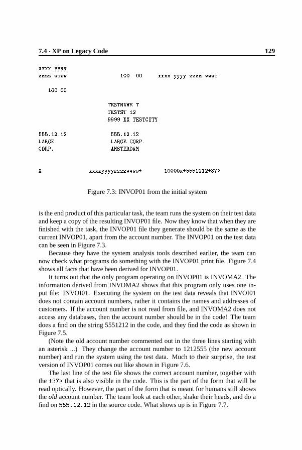
7.4 � XP on Legacy Code 129
������� � ������ � � � ��� � � ����� ��� ������ ��� ��� � � � � � � � �
����� ���
��� � � � �� � ���� � � ��� � �������� ��� ��� ��� � �
����� � � � � � � ����� � � � � � ��� � � � �� � � � �� � � � �� � � � �� ������� ����
� �������������� � � � ����� � �&! ��������� ��! ����� � � � � ! �����
Figure 7.3: INVOP01 from the initial system
is the end product of this particular task, the team runs the system on their test dataand keep a copy of the resulting INVOP01 file. Now they know that when they arefinished with the task, the INVOP01 file they generate should be the same as thecurrent INVOP01, apart from the account number. The INVOP01 on the test datacan be seen in Figure 7.3.
Because they have the system analysis tools described earlier, the team cannow check what programs do something with the INVOP01 print file. Figure 7.4shows all facts that have been derived for INVOP01.
It turns out that the only program operating on INVOP01 is INVOMA2. Theinformation derived from INVOMA2 shows that this program only uses one in-put file: INVOI01. Executing the system on the test data reveals that INVOI01does not contain account numbers, rather it contains the names and addresses ofcustomers. If the account number is not read from file, and INVOMA2 does notaccess any databases, then the account number should be in the code! The teamdoes a find on the string 5551212 in the code, and they find the code as shown inFigure 7.5.
(Note the old account number commented out in the three lines starting withan asterisk ...) They change the account number to 1212555 (the new accountnumber) and run the system using the test data. Much to their surprise, the testversion of INVOP01 comes out like shown in Figure 7.6.
The last line of the test file shows the correct account number, together withthe � ���� that is also visible in the code. This is the part of the form that will beread optically. However, the part of the form that is meant for humans still showsthe old account number. The team look at each other, shake their heads, and do afind on �� � � � � � �
in the source code. What shows up is in Figure 7.7.
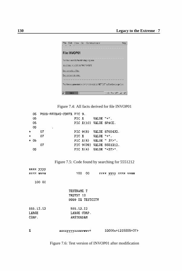
130 Legacy to the Extreme � 7
Figure 7.4: All facts derived for file INVOP01���������������� ��������������������������� ������� ����� �"!$#�!%���� ��������&(')�+*,����� ��-�������.���� �
/ ��0 �������1&32+*4����� �52�0�6��7891�/ ��0 ������� ����� �"!$#�!%�/ ��� ��������&:7�*4����� �"!;8�0<�!%�
��0 �������1&3���+*,����� �������+'=9+'=91���� ��������&:7�*4����� �"!$#�8�0<�!%�
Figure 7.5: Code found by searching for 5551212>�>�>�>�?�?�?�?@�@�@�@�A�A�A�A ')���B��� >�>�>�>C?�?�?�?�@�@�@�@�A�A�A�A
'$�������
����-������D��5�����-���-��E')9���������������F-���F�)��G
�����1�H'=9��H')9 �������H'=91�H'=9������� ���������5�������.�������.� ��DF-������� ��D
� >�>�>�>�?�?�?�?�@�@�@�@�A�A�A�A # ')������� > #+'=9+'=��������#�8�0�<
Figure 7.6: Test version of INVOP01 after modification

7.5 � Conclusions 131
��� � ���� � �� � � � � ��� � ���� � � �� �� �� � � ������� � ���� � � ����� � � � � � � � �
��� � ���� � �� � � ������� � ���� � � ����� � � � � � � � �� � � ������� � ���� � � �� �� �� � � � ������ ���� � � �� � � � �� � � � � �
Figure 7.7: Code found by searching for 555.12.12
They change the two(!) account numbers and run the test again. Now every-thing comes out as expected. They write a todo item that this part of the codeneeds urgent refactoring, or maybe they immediately implement a procedure thatformats account numbers. Or maybe the system can be left to die and they canspend their time on an XP reimplementation of the whole system.
7.5 Conclusions
In this paper we have looked at extreme programming from the viewpoint of legacysystems. We observed that the programming environment used for regular XPprojects provides capabilities not available for most mainframe-based legacy sys-tems. At the same time we described progress in the area of reverse engineeringtools that can be used to overcome these limitations. We used these findings tocome up with a way to adopt XP practices during legacy system software mainte-nance.

132 Legacy to the Extreme � 7

Chapter 8
Conclusions
In the introduction to this thesis, three research questions have been posed. Theywere:
� How can we reduce the search space when searching for a particular artifactin a legacy software system?
� How can we obtain sufficiently detailed information about a legacy softwaresystem to perform a structural change (semi-)automatically?
� How can we alter the software engineering process such that we no longerproduce legacy systems?
8.1 Reduce Search Space
In Chapter 2, it was shown how we can use a number of analysis techniques,lexical analysis being the prime one, to derive facts from a legacy system. A toolarchitecture for performing such analyses was described. Using these techniques,a call-dependency analysis, or a data-usage analysis can be made of a system.The results from such an analysis reduce the search space of someone lookingfor a particular artifact because, for instance, they are looking for a module thatmodifies a particular piece of data.
Chapter 3 builds on those results by integrating all analyses in a compact,browseable presentation format. This way, all analysis results are readily available,and are all linked to each other. An engineer can move easily from an overviewof all modules in a system, to an overview of all modules that operate on a pieceof data, to an overview of all modules that actually modify that piece of data, andso on. Building these documentation generators gets facilitated by so-called islandgrammars, an analysis technique which borrows from lexical analysis its flexibil-ity, and from syntactic analysis its thoroughness.

134 Conclusions � 8
8.2 Information for Structural Change
Since legacy systems are usually very large, the amount of facts extracted fromthem is usually large too. Somehow, this information needs to be filtered, prefer-ably automatically. One way of automatically filtering is to try to derive an object-oriented design from an existing, non-object-oriented system. Once this design isderived, the actual structural change can be performed manually. Chapter 4 exam-ines two methods that can be used for the automatic derivation of objects. Thesemethods use exactly the facts that can be derived using the techniques developedin the earlier chapters. Although deriving an object-oriented design completelyautomatically from a legacy system turns out to be undesirable, if not impossible,the techniques examined in this chapter do support the human engineer in auto-matically relating data and procedures. Having this information available is a verygood starting point for an actual object-oriented redesign.
Another way to interpret the derived facts is by automatically grouping thedata in a system by the concept they are related to. That is, to group data of thesame type. Chapter 5 uses a technique called type-inference to infer the type of avariable in a system. Using type inference, a variable can be determined to holdeither a date, or a monetary value, or a social-security number, etcetera. Using theconcept analysis from Chapter 5 on programs and the inferred type of the variablesthey use appears to give a better starting point for an object-oriented redesign thanusing just the variables.
When we are looking for detailed information, even syntactical analysis in it-self will not, in general be enough. Usually, a number of syntactical analyses needto be performed to get the right fact out of the system. More often than not, theseanalyses have a conditional dependency, and they use each others results as in-put. Having a system that allows for the elegant and concise development of suchcombinations of analyses is the topic of Chapter 6. In it, a form of parse tree traver-sal is developed that can be used to perform exactly the kinds of interdependentsyntactical analyses as described.
8.3 Altering the Software Engineering Process
New insights have improved the software engineering process over the last decades.These improvements are usually only applied to software development (the build-ing of new software systems), not to software maintenance. In Chapter 7 the re-lation of the techniques developed earlier in this thesis to a software developmentprocess called “Extreme Programming” is examined. Furthermore, the feasibilityof applying this process to the maintenance of legacy systems is discussed. Usingthis, or a similar methodology, and supported by the right analysis techniques, ateam of engineers can maintain a legacy system in such a way that it stops beinga legacy system, and becomes an understandable, modifiable, and maintainablesystem, once again.

Bibliography
[AKW88] A. V. Aho, B. W. Kernighan, and P. J. Weinberger. The AWK Program-ming Language. Addison-Wesley, 1988.
[B�
00] M.G.J. van den Brand et al. The ASF+SDF Meta-Environment: acomponent-based language development environment. Submitted forpublication, 2000.
[Bec99] K. Beck. Extreme Programming Explained. Embrace Change. AddisonWesley, 1999.
[BHB99] I. T. Bowman, R. C. Holt, and N. V. Brewster. Linux as a case study:Its extracted software architecture. In 21st International Conference onSoftware Engineering, ICSE-99, pages 555–563. ACM, 1999.
[BHK89] J. A. Bergstra, J. Heering, and P. Klint. The algebraic specificationformalism asf. In Algebraic Specification, chapter 1, pages 1–66. TheACM Press in cooperation with Addison-Wesley, 1989.
[BJKO00] M.G.J. van den Brand, H.A. de Jong, P. Klint, and P.A. Olivier. Ef-ficient Annotated Terms. Software, Practice & Experience, 30(3):259–291, 2000.
[BK94] J. A. Bergstra and P. Klint. The ToolBus: a component interconnectionarchitecture. Technical Report P9408, University of Amsterdam, Pro-gramming Research Group, 1994. Available from http://www.science.uva.nl/research/prog/reports/reports.html.
[BK98] J. A. Bergstra and P. Klint. The discrete time ToolBus – a software coor-dination architecture. Science of Computer Programming, 31(2-3):205–229, July 1998.
[BL76] L. A. Belady and M. M. Lehman. A model of large program develop-ment. IBM Systems Journal, 15(3):225–252, 1976.

136 BIBLIOGRAPHY
[BM97] E. Burd and M. Munro. Enriching program comprehension for soft-ware reuse. In International Workshop on Program Comprehension;IWCP’97. IEEE Computer Society, 1997.
[BMW96] E. Burd, M. Munro, and C. Wezeman. Extracting reusable modulesfrom legacy code: Considering the issues of module granularity. In3rd Working Conference on Reverse Engineering; WCRE’96, pages 189–196. IEEE Computer Society, 1996.
[Boe88] B. W. Boehm. A spiral model of software development and enhancement.IEEE Computer, 21(5), 1988.
[dB�
96] M. G. J. van den Brand et al. Industrial applications of ASF+SDF. InAlgebraic Methodology and Software Technology (AMAST’96), volume1101 of LNCS, pages 9–18. Springer-Verlag, 1996.
[dBKV96] M. G. J. van den Brand, P. Klint, and C. Verhoef. Core technologiesfor system renovation. In K.G. Jeffery, J. Kral, and M. Bartosek, edi-tors, SOFSEM’96: Theory and Practice of Informatics, volume 1175 ofLNCS, pages 235–255. Springer-Verlag, 1996.
[dBSV97a] M. G. J. van den Brand, A. Sellink, and C. Verhoef. Generation ofcomponents for software renovation factories from context-free gram-mars. In Fourth Working Conference on Reverse Engineering; WCRE’97,pages 144–155. IEEE Computer Society, 1997.
[dBSV97b] M. G. J. van den Brand, M. P. A. Sellink, and C. Verhoef. Obtaining aCobol grammmar from legacy code for reengineering purposes. In Pro-ceedings of the 2nd international workshop on the theory and practice ofalgebraic specifications, Electronic workshops in computing. SpringerVerlag, 1997.
[dBSV98] M. G. J. van den Brand, M. P. A. Sellink, and C. Verhoef. Current pars-ing techniques in software renovation considered harmful. In Proceed-ings of the sixth International Workshop on Program Comprehension,pages 108–117. IEEE, 1998.
[Bro83] R. Brooks. Towards a theory of the comprehension of computer pro-grams. Int. Journal of Man-Machine Studies, 18:543–554, 1983.
[Bro91] P. Brown. Integrated hypertext and program understanding tools. IBMSystems Journal, 30(3):363–392, 1991.
[BS95] M. L. Brodie and M. Stonebraker. Migrating Legacy Systems: Gateways,interfaces and the incremental approach. Morgan Kaufman Publishers,1995.

BIBLIOGRAPHY 137
[BV95] J. C. M. Baeten and C. Verhoef. Concrete process algebra. In Hand-book of Logic in Computer Science, volume 4, pages 149–268. Claren-don Press, Oxford, 1995.
[BYM�
98] I. D. Baxter, A. Yahin, L. Moura, M. Sant’Anna, and L. Bier. Clonedetection using abstract syntax trees. In International Conference onSoftware Maintenance, ICSM’98, pages 368–377. IEEE Computer Soci-ety Press, 1998.
[CB91] G. Caldiera and V. R. Basili. Identifying and qualifying reusable softwarecomponents. IEEE Computer, pages 61–70, February 1991.
[CC90] E. J. Chikofsky and J. H. Cross. Reverse engineering and design recov-ery: A taxonomy. IEEE Software, 7(1):13–17, 1990.
[CCM96] G. Canfora, A. Cimitile, and M. Munro. An improved algorithmfor identifying objects in code. Software—Practice and Experience,26(1):25–48, 1996.
[CDDF99] A. Cimitile, A. De Lucia, G. A. Di Lucca, and A. R. Fasolino. Identi-fying objects in legacy systems using design metrics. Journal of Systemsand Software, 44(3):199–211, 1999.
[CFKW95] Y.-F. Chen, G. S. Fowler, E. Koutsofios, and R. S. Wallach. Ciao:A graphical navigator for software and document repositories. InG. Caldiera and K. Bennett, editors, Int. Conf. on Software Maintenance;ICSM 95, pages 66–75. IEEE Computer Society, 1995.
[CK99] Horatiu Cirstea and Claude Kirchner. Introduction to the rewriting cal-culus. Rapport de recherche 3818, INRIA, December 1999.
[CV95] A. Cimitile and G. Visaggio. Software salvaging and the call dominancetree. Journal of Systems Software, 28:117–127, 1995.
[DDF�
97] A. De Lucia, G. A. Di Lucca, A. R. Fasolino, P. Guerra, andS. Petruzzelli. Migrating legacy systems towards object-oriented plat-forms. In International Conference on Software Maintenance; ICSM’97,pages 122–129. IEEE Computer Society, 1997.
[DK97] A. van Deursen and T. Kuipers. Finding classes in legacy code usingcluster analysis. In S. Demeyer and H. Gall, editors, Proceedings ofthe ESEC/FSE’97 Workshop on Object-Oriented Reengineering. ReportTUV-1841-97-10, Technical University of Vienna, 1997.

138 BIBLIOGRAPHY
[DK98] A. van Deursen and T. Kuipers. Rapid system understanding: TwoCOBOL case studies. In S. Tilley and G. Visaggio, editors, Sixth In-ternational Workshop on Program Comprehension; IWPC’98, pages 90–98. IEEE Computer Society, 1998. Also published as Chapter 2 of thisthesis.
[DHK96] A. van Deursen, J. Heering, and P. Klint, editors. Language Prototyp-ing: An Algebraic Specification Approach, volume 5 of AMAST Series inComputing. World Scientific Publishing Co., 1996.
[DK98] A. van Deursen and P. Klint. Little languages, little maintenance? Jour-nal of Software Maintenance, 10(2):75–92, 1998.
[DK99a] A. van Deursen and T. Kuipers. Building documentation generators.In International Conference on Software Maintenance, ICSM’99, pages40–49. IEEE Computer Society, 1999. Also published as Chapter 3 ofthis thesis.
[DK99b] A. van Deursen and T. Kuipers. Identifying objects using cluster andconcept analysis. In 21st International Conference on Software Engi-neering, ICSE-99, pages 246–255. ACM, 1999. Also published as Chap-ter 4 of this thesis.
[DM98] A. van Deursen and L. Moonen. Type inference for COBOL systems. InI. Baxter, A. Quilici, and C. Verhoef, editors, Proc. 5th Working Conf. onReverse Engineering, pages 220–230. IEEE Computer Society, 1998.
[DM99] A. van Deursen and L. Moonen. Understanding COBOL systems usingtypes. In Proceedings 7th Int. Workshop on Program Comprehension,IWPC’99, pages 74–83. IEEE Computer Society, 1999.
[dOBvSdPL98] Ch. de Oliveira Braga, A. von Staa, and J. C. S. do Prado Leite.Documentu: A flexible architecture for documentation production basedon a reverse-engineering strategy. Journal of Software Maintenance,10:279–303, 1998.
[EHM�
99] P. H. Eidorff, F. Henglein, C. Mossin, H. Niss, M. H. Sorensen, andM. Tofte. Anno Domini: From type theory to Year 2000 conversion tool.In 26th Annual Symposium on Principles of Programming Languages,POPL’99. ACM, 1999. To appear.
[FGK88] E. B. Fowlkes, R. Gnanadesikan, and J. R. Kettenring. Variable selectionin clustering. Journal of Classification, 5:205–228, 1988.
[FHK�
97] P. J. Finnigan, R. C. Holt, I. Kalas, S. Kerr, K.Kontogiannis, H. A.Muller, J. Mylopoulos, and S. G. Perelgut. The software bookshelf. IBMSystems Journal, 36(4):564–593, 1997.

BIBLIOGRAPHY 139
[FRS94] H. Fergen, P. Reichelt, and K. P. Schmidt. Bringing objects intoCOBOL: MOORE - a tool for migration from COBOL85 to object-oriented COBOL. In Proc. Conf. on Technology of Object-Oriented Lan-guages and Systems (TOOLS 14), pages 435–448. Prentice-Hall, 1994.
[GAM96] W. G. Griswold, D. C. Atkinson, and C. McCurdy. Fast, flexible syn-tactic pattern matching and processing. In Fourth Workshop on ProgramComprehension; IWPC’96. IEEE Computer Society, 1996.
[GHJV94] E. Gamma, R. Helm, R. Johnson, and J. Vlissides. Design Patterns:Elements of Reusable Object-Oriented Software. Addison-Wesley, 1994.
[GKNV93] E. R. Gansner, E. Koutsofios, S. North, and K-P. Vo. A technique fordrawing directed graphs. IEEE Transactions on Software Engineering,19(3):214–230, 1993.
[GW99] B. Ganter and R. Wille. Formal Concept Analysis: Mathematical Foun-dations. Springer, 1999.
[HHKR89] J. Heering, P. R. H. Hendriks, P. Klint, and J. Rekers. The syn-tax definition formalism SDF — Reference manual. SIGPLAN Notices,24(11):43–75, 1989.
[JV00] M. de Jonge and Joost Visser. Grammars as contracts. In Generativeand Component-based Software Engineering (GCSE), Erfurt, Germany,October 2000. CD-ROM Proceedings. To be published in Lecture Notesin Computer Science (LNCS), Springer.
[JVV00] M. de Jonge, Eelco Visser, and Joost Visser. XT: a bundle of programtransformation tools. Submitted for publication, 2000.
[KC99] R. Kazman and J. Carriere. Playing detective: Reconstructing softwarearchitecture from available evidence. Automated Software Engineering,6:107–138, 1999.
[KL�
97] Gregor Kiczales, John Lamping, et al. Aspect-oriented programming.In Proceedings of ECOOP’97, number 1241 in LNCS. Springer Verlag,1997.
[Kli93] P. Klint. A meta-environment for generating programming environments.ACM Transactions on Software Engineering and Methodology, 2:176–201, 1993.
[KLV00] Jan Kort, Ralf Lammel, and Joost Visser. Functional transformationsystems. In 9th International Workshop on Functional and Logic Pro-gramming, Benicassim, Spain, September 2000.

140 BIBLIOGRAPHY
[KM00] T. Kuipers and L. Moonen. Types and concept analysis for legacy sys-tems. In Proceedings of the International Workshop on ProgrammingComprehension (IWPC 2000). IEEE Computer Society, June 2000. Alsopublished as Chapter 5 of this thesis.
[Knu84] D.E. Knuth. Literate programming. The Computer Journal, 27(2):97–111, 1984.
[KR90] L. Kaufman and P. J. Rousseeuw. Finding Groups in Data: An Introduc-tion to Cluster Analysis. John Wiley, 1990.
[Lak97] A. Lakhotia. A unified framework for expressing software subsystemclassification techniques. Journal of Systems and Software, pages 211–231, March 1997.
[LHGF88] L. D. Landis, P. M. Hyland, A. L. Gilbert, and A. J. Fine. Documen-tation in a software maintenance environment. In Proc. Conference onSoftware Maintenance, pages 66–73. IEEE Computer Society, 1988.
[LS97] C. Lindig and G. Snelting. Assessing modular structure of legacy codebased on mathematical concept analysis. In 19th International Confer-ence on Software Engineering, ICSE-19, pages 349–359. ACM, 1997.
[LVK00] Ralf Lammel, Joost Visser, and Jan Kort. Dealing with large bananas.In Johan Jeuring, editor, Workshop on Generic Programming, Ponte deLima, July 2000. Technical Report, Universiteit Utrecht.
[LW90] S. S. Liu and N. Wilde. Identifying objects in a conventional proce-dural language: An example of data design recovery. In InternationalConference on Software Maintenance; ICSM’90, pages 266–271. IEEEComputer Society, 1990.
[MV96] A. von Mayrhauser and A. M. Vans. Identification of dynamic compre-hension processes during large scale maintenance. IEEE Transactions onSoftware Engineering, 22(6):424–438, 1996.
[MV97] A. von Mayrhauser and A. M. Vans. Hypothesis-driven understandingprocesses during corrective maintenance of large scale software. In Inter-national Conference on Software Maintenance; ICSM’97, pages 12–20.IEEE Computer Society, 1997.
[Mey97] B. Meyer. Object-Oriented Software Construction. Prentice Hall, secondedition, 1997.
[Mic96] Micro Focus Revolve user guide. Burl Software Laboratories Inc., USA,1996.

BIBLIOGRAPHY 141
[MN96] G. C. Murphy and D. Notkin. Lightweight lexical source model ex-traction. ACM Transactions on Software Engineering Methodology,5(3):262–292, 1996.
[MNB�
94] L. Markosian, P. Newcomb, R. Brand, S. Burson, and T. Kitzmiller.Using an enabling technology to reengineer legacy systems. Communi-cations of the ACM, 37(5):58–70, 1994. Special issue on reverse engi-neering.
[Moo97] L. Moonen. A generic architecture for data flow analysis to support re-verse engineering. In A. Sellink, editor, Theory and Practice of AlgebraicSpecifications; ASF+SDF’97, Electronic Workshops in Computing, Am-sterdam, September 1997. Springer-Verlag.
[MOTU93] H. A. Muller, M. A. Orgun, S. R. Tilley, and J. S. Uhl. A reverseengineering approach to subsystem structure identification. Journal ofSoftware Maintenance, 5(4):181–204, 1993.
[Nei96] J. M. Neighbors. Finding reusable software components in large systems.In 3rd Working Conference on Reverse Engineering; WCRE’96, pages2–10. IEEE Computer Society, 1996.
[NK95] P. Newcomb and G. Kottik. Reengineering procedural into object-oriented systems. In Second Working Conference on Reverse Engineer-ing; WCRE’95, pages 237–249. IEEE Computer Society, 1995.
[OT93] C. L. Ong and W. T. Tsai. Class and object extraction from imperativecode. Journal of Object-Oriented Programming, pages 58–68, March–April 1993.
[Ous94] J. K. Ousterhout. Tcl and the Tk Toolkit. Addison-Wesley, 1994.
[Pig97] T. M. Pigoski. Practical Software Maintenance – Best Practices for Man-aging Your Software Investment. John Wiley and Sons, 1997.
[PXL95] Jens Palsberg, Cun Xiao, and Karl Lieberherr. Efficient implementationof adaptive software. ACM Transactions on Programming Languagesand Systems, 17(2):264–292, March 1995.
[Raj97] Vaclav Rajlich. Incremental redocumentation with hypertext. In 1st Eu-romicro Working Conference on Software Maintenance and Reengineer-ing CSMR 97. IEEE Computer Society Press, 1997.
[Rek92] J. Rekers. Parser Generation for Interactive Environments. PhD thesis,University of Amsterdam, 1992.

142 BIBLIOGRAPHY
[RFT99] G. Ramalingam, J. Field, and F. Tip. Aggregate structure identificationand its application to program analysis. In 26th Annual Symposium onPrinciples of Programming Languages, POPL’99. ACM, 1999. To ap-pear.
[Sch91] R. W. Schwanke. An intelligent tool for re-engineering software modu-larity. In 13th International Conference on Software Engineering, ICSE-13, pages 83–92. ACM, 1991.
[SCHC99] S. E. Sim, C. L. A. Clarke, R. C. Holt, and A. M. Cox. Browsing andsearching software architectures. In Int. Conf. on Software Maintenance,ICSM’99, pages 381–390. IEEE Computer Society, 1999.
[SH98] S. E. Sim and R. C. Holt. The ramp-up problem in software projects: Acase study of how software immigrants naturalize. In 20th Int. Conf. onSoftware Engineering; ICSE-98, pages 361–370. ACM, 1998.
[SN95] H. M. Sneed and E. Nyary. Extracting object-oriented specification fromprocedurally oriented programs. In Second Working Conference on Re-verse Engineering; WCRE’95, pages 217–226. IEEE Computer Society,1995.
[Sne92] H. M. Sneed. Migration of procedurally oriented COBOL programs inan object-oriented architecture. In International Conference on SoftwareMaintenance; ICSM’92, pages 105–116. IEEE Computer Society, 1992.
[Sne96] G. Snelting. Reengineering of configurations based on mathemati-cal concept analysis. ACM Transactions on Software Engineering andMethodology, 5(2):146–189, April 1996.
[Sne98] G. Snelting. Concept analysis — a new framework for program under-standing. In Proceedings of the ACM SIGPLAN/SIGSOFT Workshopon Program Analysis for Software Tools and Engineering (PASTE’98),1998. SIGPLAN Notices 33(7).
[Sne00] G. Snelting. Software reengineering based on concept lattices. In Pro-ceedings of the 4th European Conference on Software Maintenance andReengineering (CSMR’00). IEEE Computer Society, 2000. To appear.
[SR97] M. Siff and T. Reps. Identifying modules via concept analysis. In In-ternational Conference on Software Maintenance, ICSM97. IEEE Com-puter Society, 1997.
[ST98] G. Snelting and F. Tip. Reengineering class hierarchies using conceptanalysis. In Foundations of Software Engineering, FSE-6, pages 99–110.ACM, 1998. SIGSOFT Software Engineering Notes 23(6).

BIBLIOGRAPHY 143
[Swa76] E. B. Swanson. The dimensions of maintenance. In Proceedings of theSecond International Conference on Software Engineering, pages 492–497. ACM, 1976.
[TL95] H. B. K. Tan and T. W. Ling. Recovery of object-oriented design from ex-isting data-intensive business programs. Information and Software Tech-nology, 37(2):67–77, 1995.
[Tom85] M. Tomita. Efficient Parsing for Natural Languages. A Fast Algorithmfor Practical Systems. Kluwer Academic Publishers, 1985.
[V�
] E. Visser et al. The online survey of program transformation. http://www.program-transformation.org/survey.html.
[VBT99] Eelco Visser, Zine-el-Abidine Benaissa, and Andrew Tolmach. Buildingprogram optimizers with rewriting strategies. ACM SIGPLAN Notices,34(1):13–26, January 1999. Proceedings of the International Conferenceon Functional Programming (ICFP’98).
[Vis97a] E. Visser. Scannerless Generalized-LR Parsing. Technical Report P9707,University of Amsterdam, Programming Research Group, 1997.
[Vis97b] E. Visser. Syntax Definition for Language Prototyping. PhD thesis,University of Amsterdam, 1997.
[WAKS97] D. C. Wang, A. W. Appel, J. L. Korn, and C. S. Serra. The Zephyr ab-stract syntax description language. In Proceedings of the USENIX Con-ference on Domain-Specific Languages, pages 213–28, Berkeley, CA,October 15–17 1997. USENIX Association.
[WBF97] T. Wiggerts, H. Bosma, and E. Fielt. Scenarios for the identificationof objects in legacy systems. In I.D. Baxter, A. Quilici, and C. Verhoef,editors, 4th Working Conference on Reverse Engineering, pages 24–32.IEEE Computer Society, 1997.
[Wig97] T. Wiggerts. Using clustering algorithms in legacy systems remodular-ization. In 4th Working Conference on Reverse Engineering, pages 33–43. IEEE Computer Society, 1997.
[WS91] L. Wall and R. L. Schwarz. Programming Perl. O’Reilly & Associates,Inc., 1991.
[WTMS95] K. Wong, S.R. Tilley, H.A. Muller, and M.-A.D. Storey. Structuralredocumentation: a case study. IEEE Software, 12(1):46–54, 1995.
[YRK99] R. J. Yarger, G. Reese, and T. King. MySQL & mSQL. O’Reilly, 1999.http://www.mysql.org/.

144 BIBLIOGRAPHY
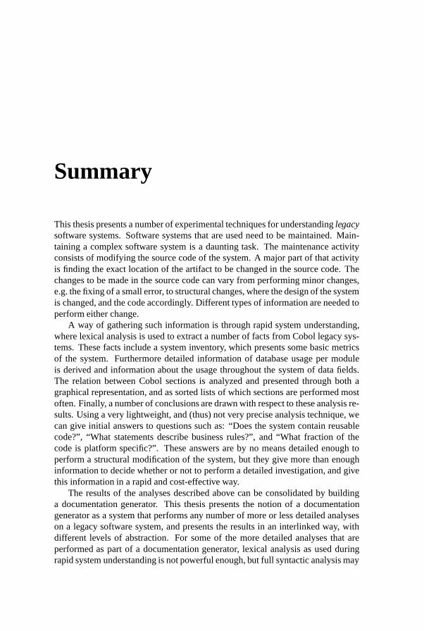
Summary
This thesis presents a number of experimental techniques for understanding legacysoftware systems. Software systems that are used need to be maintained. Main-taining a complex software system is a daunting task. The maintenance activityconsists of modifying the source code of the system. A major part of that activityis finding the exact location of the artifact to be changed in the source code. Thechanges to be made in the source code can vary from performing minor changes,e.g. the fixing of a small error, to structural changes, where the design of the systemis changed, and the code accordingly. Different types of information are needed toperform either change.
A way of gathering such information is through rapid system understanding,where lexical analysis is used to extract a number of facts from Cobol legacy sys-tems. These facts include a system inventory, which presents some basic metricsof the system. Furthermore detailed information of database usage per moduleis derived and information about the usage throughout the system of data fields.The relation between Cobol sections is analyzed and presented through both agraphical representation, and as sorted lists of which sections are performed mostoften. Finally, a number of conclusions are drawn with respect to these analysis re-sults. Using a very lightweight, and (thus) not very precise analysis technique, wecan give initial answers to questions such as: “Does the system contain reusablecode?”, “What statements describe business rules?”, and “What fraction of thecode is platform specific?”. These answers are by no means detailed enough toperform a structural modification of the system, but they give more than enoughinformation to decide whether or not to perform a detailed investigation, and givethis information in a rapid and cost-effective way.
The results of the analyses described above can be consolidated by buildinga documentation generator. This thesis presents the notion of a documentationgenerator as a system that performs any number of more or less detailed analyseson a legacy software system, and presents the results in an interlinked way, withdifferent levels of abstraction. For some of the more detailed analyses that areperformed as part of a documentation generator, lexical analysis as used duringrapid system understanding is not powerful enough, but full syntactic analysis may

146 Summary
be too restrictive, or too expensive. This thesis introduces the notion of islandgrammars, from which an analysis can be generated that is liberal when analyzingthe larger part of the source code (the “water”), but very strict when analyzing therelevant part (the “island”).
A documentation generator integrates manual documentation with the auto-matically generated documentation. It utilizes graphical, hyperlinked representa-tions of dependencies between different types of modules, data files, databases,and so on.
When looking to alter a system structurally, structure must be imposed on alargely unstructured, or not-well-enough structured system. One way of imposingstructure is to migrate a procedural system to an object-oriented system. This the-sis compares two techniques for relating data and procedures from a proceduralsystem, so to act as a starting point for an object-oriented (re-)design of that sys-tem. These techniques are cluster analysis and concept analysis. Cluster analysisworks by calculating a distance between various objects, and group the objects thatare less than a certain distance from each other in a single cluster. Here, the dis-tance is calculated between different data fields in a system, where distance relatesto whether or not they are used in the same modules. Concept analysis groupsrelated items with their features into “concepts”. Concepts are maximal subsets ofitems sharing exactly the same features. Here, the items are data fields, and theproperties they have are the modules they are used in.
Concept analysis appears to be better suited for object identification than clus-ter analysis. A case study shows that when deriving certain data fields from aCobol software system, and ignoring others, the concept analysis of data fieldsand the modules they are used in results in a starting point for an object-orientedremodeling of the original software system.
Legacy software systems are largely untyped. This makes systems harder tomaintain, in part because it is hard to find the “relevant” data in a system. Typeinference can alleviate this problem in part. All the data fields in a system aregrouped together in types, based on the way they interact with each other. Usingthese types as items in a concept analysis, instead of plain data fields, greatlyimproves the result of the concept analysis as a starting point for an object-orientedremodeling of the system.
In order to perform analysis on software systems such as those needed fortype inference, the system must be parsed, and the parse trees must be analyzed.This thesis presents a system that lets a software engineer access parse trees in anobject-oriented fashion. The system also presents the engineer with tree traversals,allowing him to focus on specific analyses while selecting one of the traversalstrategies presented by the system. Analyses written using this system can beeasily linked to all sorts of applications.
Extreme programming is a software engineering methodology that bundles anumber of programming practices and tries to make their interdependency explicit.

Summary 147
Extreme programming focuses on changeability of systems. A system developedusing the extreme programming methodology should be ready for any changeits owner needs from the system, be it minor or structural. The last chapter ofthis thesis examines whether the techniques used in extreme programming can beretrofitted to legacy system maintenance in order to improve the understanding of,and ultimately the changeability of such a system.

148 Summary
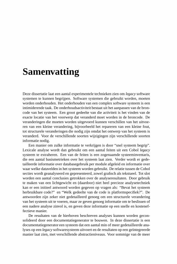
Samenvatting
Deze dissertatie laat een aantal experimentele technieken zien om legacy softwaresystemen te kunnen begrijpen. Software systemen die gebruikt worden, moetenworden onderhouden. Het onderhouden van een complex software systeem is eenintimiderende taak. De onderhoudsactiviteit bestaat uit het aanpassen van de bron-code van het systeem. Een groot gedeelte van die activiteit is het vinden van deexacte locatie van het voorwerp dat veranderd moet worden in de broncode. Deveranderingen die moeten worden uitgevoerd kunnen verschillen van het uitvoe-ren van een kleine verandering, bijvoorbeeld het repareren van een kleine fout,tot structurele veranderingen die nodig zijn omdat het ontwerp van het systeem isveranderd. Voor de verschillende soorten wijzigingen zijn verschillende soorteninformatie nodig.
Een manier om zulke informatie te verkrijgen is door “snel systeem begrip”.Lexicale analyse wordt dan gebruikt om een aantal feiten uit een Cobol legacysysteem te extraheren. Een van de feiten is een zogenaamde systeeminventaris,die een aantal basismetrieken over het systeem laat zien. Verder wordt er gede-tailleerde informatie over databasegebruik per module afgeleid en informatie overwaar welke datavelden in het systeem worden gebruikt. De relatie tussen de Cobolsecties wordt geanalyseerd en gepresenteerd, zowel grafisch als tekstueel. Tot slotworden een aantal conclusies getrokken over de analyseresultaten. Door gebruikte maken van een lichtgewicht en (daardoor) niet heel precieze analysetechniekkan er een initieel antwoord worden gegeven op vragen als: “Bevat het systeemherbruikbare code?” en “Welk gedeelte van de code is platformspecifiek?”. Deantwoorden zijn zeker niet gedetailleerd genoeg om een structurele veranderingvan het systeem uit te voeren, maar ze geven genoeg informatie om te beslissen ofeen nadere analyse zinvol is, en geven deze informatie op een snelle en kostenef-fectieve manier.
De resultaten van de hierboven beschreven analyses kunnen worden gecon-solideerd door een documentatiegenerator te bouwen. In deze dissertatie is eendocumentatiegenerator een systeem dat een aantal min of meer gedetailleerde ana-lyses op een legacy softwaresysteem uitvoert en de resultaten op een geıntegreerdemanier laat zien, met verschillende abstractieniveaus. Voor sommige van de meer

150 Samenvatting
gedetailleerde analyses die worden uitgevoerd als onderdeel van de documenta-tiegenerator is lexicale analyse niet krachtig genoeg, maar volledige syntactischeanalyse te beperkend, of te duur. Deze dissertatie introduceert de notie van “ei-landgrammatica’s”, waaruit analyses gegenereerd kunnen worden die liberaal zijnwanneer ze het grootste gedeelte van de broncode analyseren (het “water”), maarzeer nauwkeurig als ze het relevante gedeelte van de broncode analyseren (het“eiland”).
Een documentatiegenerator integreert handmatige documentatie met automa-tisch gegenereerde documentatie. De generator gebruikt grafische, gehyperlinkterepresentaties van de afhankelijkheden tussen verschillende soorten van modules,databestanden, databases enzovoorts.
Als een systeem structureel veranderd moet worden dan moet er een struc-tuur worden opgelegd aan een grotendeels ongestructureerd, of in ieder geval nietgoed genoeg gestructureerd systeem. Een manier om zo’n structuur af te dwin-gen is een procedureel systeem te migreren naar een object-georienteerd systeem.Deze dissertatie vergelijkt twee technieken om de gegevens en de procedures vaneen procedureel systeem aan elkaar te relateren, om zo een beginpunt te vormenvoor een object-georienteerd (her-)ontwerp van dat systeem. Deze technieken zijn“clusteranalyse” en “conceptanalyse”. Clusteranalyse werkt door een afstand teberekenen tussen verschillende objecten en de objecten die minder dan een zekereafstand van elkaar liggen te groeperen in een cluster. In dit geval wordt de af-stand tussen verschillende datavelden in een systeem berekend, gebaseerd op hetfeit dat datavelden al dan niet in dezelfde module worden gebruikt. Conceptana-lyse groepeert gerelateerde voorwerpen met hun kenmerken in “concepten”. Eenconcept is een maximale deelverzameling van voorwerpen die exact dezelfde ken-merken hebben. In dit geval zijn de voorwerpen de datavelden en hun kenmerkende modules waar ze in gebruikt worden.
Conceptanalyse blijkt beter geschikt voor objectidentificatie dan clusterana-lyse. Een casus demonstreert dat als bepaalde datavelden van een Cobol systeemworden gebruikt als voorwerpen (en bepaalde andere datavelden niet) de concept-analyse van die velden en hun bijbehorende modules leidt tot een beginpunt vooreen object-georienteerd herontwerp van het originele systeem.
Legacy systemen zijn grotendeels ongetypeerd. Dit zorgt ervoor dat de syste-men moeilijker zijn te onderhouden, ten dele omdat het moeilijk is de “relevante”gegevens in een systeem te vinden. Type-inferentie is een manier om dit probleemdeels op te lossen. Alle datavelden in een systeem worden dan gegroepeerd in “ty-pes”, gebaseerd op de manier waarop ze met elkaar interacteren. Als deze typesgebruikt worden als voorwerpen in de conceptanalyse, in plaats van de datavelden,dan verbetert het resultaat van de conceptanalyse als beginpunt voor een heront-werp.
Om softwaresystemen te analyseren met de mate van detail die nodig is voorbijvoorbeeld type-inferentie moet het systeem geparseerd worden en de parseer-

Samenvatting 151
bomen geanalyseerd. In deze dissertatie wordt een systeem geıntroduceerd dat hetmogelijk maakt een parseerboom op object-georienteerde wijze te benaderen. Hetsysteem produceert ook zogenaamde traversals die het mogelijk maken dat degenedie de analyses schrijft zich slechts met die analyses bezig hoeft te houden. Hijkan een van de traversal-strategieen die het systeem biedt kiezen. De analyses diemet behulp van dit systeem zijn geschreven laten zich zonder moeite koppelen aaneen grote varieteit van toepassingen.
Extreme programming is een manier van software-ontwikkeling die een aan-tal programmeerpraktijken bundelt en hun wederzijdse afhankelijkheden explicietprobeert te maken. Extreme programming focust op veranderbaarheid van sys-temen. Een systeem dat is ontwikkeld met behulp van de extreme programmingmethodologie zou gereed moeten zijn voor elke verandering die de eigenaar vanhet systeem nodig heeft, zowel klein als structureel. Het laatste hoofdstuk vandeze dissertatie onderzoekt of de technieken van extreme programming met te-rugwerkende kracht kunnen worden gebruikt bij het onderhouden van een legacysysteem, om zo het begrip en uiteindelijk de veranderbaarheid van zo’n systeem teverhogen.

Titles in the IPA Dissertation Series
J.O. Blanco. The State Operator in Process Al-gebra. Faculty of Mathematics and ComputingScience, TUE. 1996-1
A.M. Geerling. Transformational Developmentof Data-Parallel Algorithms. Faculty of Mathe-matics and Computer Science, KUN. 1996-2
P.M. Achten. Interactive Functional Programs:Models, Methods, and Implementation. Facultyof Mathematics and Computer Science, KUN.1996-3
M.G.A. Verhoeven. Parallel Local Search. Fa-culty of Mathematics and Computing Science,TUE. 1996-4
M.H.G.K. Kesseler. The Implementation ofFunctional Languages on Parallel Machineswith Distrib. Memory. Faculty of Mathematicsand Computer Science, KUN. 1996-5
D. Alstein. Distributed Algorithms for HardReal-Time Systems. Faculty of Mathematics andComputing Science, TUE. 1996-6
J.H. Hoepman. Communication, Synchroniza-tion, and Fault-Tolerance. Faculty of Mathema-tics and Computer Science, UvA. 1996-7
H. Doornbos. Reductivity Arguments and Pro-gram Construction. Faculty of Mathematics andComputing Science, TUE. 1996-8
D. Turi. Functorial Operational Semantics andits Denotational Dual. Faculty of Mathematicsand Computer Science, VUA. 1996-9
A.M.G. Peeters. Single-Rail Handshake Cir-cuits. Faculty of Mathematics and ComputingScience, TUE. 1996-10
N.W.A. Arends. A Systems Engineering Specifi-cation Formalism. Faculty of Mechanical Engi-neering, TUE. 1996-11
P. Severi de Santiago. Normalisation in LambdaCalculus and its Relation to Type Inference. Fa-culty of Mathematics and Computing Science,TUE. 1996-12
D.R. Dams. Abstract Interpretation and Par-tition Refinement for Model Checking. Facultyof Mathematics and Computing Science, TUE.1996-13
M.M. Bonsangue. Topological Dualities in Se-mantics. Faculty of Mathematics and ComputerScience, VUA. 1996-14
B.L.E. de Fluiter. Algorithms for Graphs ofSmall Treewidth. Faculty of Mathematics andComputer Science, UU. 1997-01
W.T.M. Kars. Process-algebraic Transformati-ons in Context. Faculty of Computer Science,UT. 1997-02
P.F. Hoogendijk. A Generic Theory of DataTypes. Faculty of Mathematics and ComputingScience, TUE. 1997-03
T.D.L. Laan. The Evolution of Type Theory inLogic and Mathematics. Faculty of Mathematicsand Computing Science, TUE. 1997-04
C.J. Bloo. Preservation of Termination for Ex-plicit Substitution. Faculty of Mathematics andComputing Science, TUE. 1997-05
J.J. Vereijken. Discrete-Time Process Algebra.Faculty of Mathematics and Computing Science,TUE. 1997-06
F.A.M. van den Beuken. A Functional Ap-proach to Syntax and Typing. Faculty of Mathe-matics and Informatics, KUN. 1997-07
A.W. Heerink. Ins and Outs in Refusal Testing.Faculty of Computer Science, UT. 1998-01
G. Naumoski and W. Alberts. A Discrete-EventSimulator for Systems Engineering. Faculty ofMechanical Engineering, TUE. 1998-02
J. Verriet. Scheduling with Communication forMultiprocessor Computation. Faculty of Mathe-matics and Computer Science, UU. 1998-03
J.S.H. van Gageldonk. An Asynchronous Low-Power 80C51 Microcontroller. Faculty of Ma-thematics and Computing Science, TUE. 1998-04
A.A. Basten. In Terms of Nets: System Designwith Petri Nets and Process Algebra. Facultyof Mathematics and Computing Science, TUE.1998-05
E. Voermans. Inductive Datatypes with Lawsand Subtyping – A Relational Model. Facultyof Mathematics and Computing Science, TUE.1999-01

H. ter Doest. Towards Probabilistic Unification-based Parsing. Faculty of Computer Science,UT. 1999-02
J.P.L. Segers. Algorithms for the Simulation ofSurface Processes. Faculty of Mathematics andComputing Science, TUE. 1999-03
C.H.M. van Kemenade. Recombinative Evolu-tionary Search. Faculty of Mathematics and Na-tural Sciences, Univ. Leiden. 1999-04
E.I. Barakova. Learning Reliability: a Study onIndecisiveness in Sample Selection. Faculty ofMathematics and Natural Sciences, RUG. 1999-05
M.P. Bodlaender. Schedulere Optimizationin Real-Time Distributed Databases. Facultyof Mathematics and Computing Science, TUE.1999-06
M.A. Reniers. Message Sequence Chart: Syn-tax and Semantics. Faculty of Mathematics andComputing Science, TUE. 1999-07
J.P. Warners. Nonlinear approaches to satis-fiability problems. Faculty of Mathematics andComputing Science, TUE. 1999-08
J.M.T. Romijn. Analysing Industrial Proto-cols with Formal Methods. Faculty of ComputerScience, UT. 1999-09
P.R. D’Argenio. Algebras and Automata forTimed and Stochastic Systems. Faculty of Com-puter Science, UT. 1999-10
G. Fabian. A Language and Simulator for Hy-brid Systems. Faculty of Mechanical Engineer-ing, TUE. 1999-11
J. Zwanenburg. Object-Oriented Concepts andProof Rules. Faculty of Mathematics and Com-puting Science, TUE. 1999-12
R.S. Venema. Aspects of an Integrated NeuralPrediction System. Faculty of Mathematics andNatural Sciences, RUG. 1999-13
J. Saraiva. A Purely Functional Implementationof Attribute Grammars. Faculty of Mathematicsand Computer Science, UU. 1999-14
R. Schiefer. Viper, A Visualisation Tool for Pa-rallel Progam Construction. Faculty of Mathe-matics and Computing Science, TUE. 1999-15
K.M.M. de Leeuw. Cryptology and Statecraftin the Dutch Republic. Faculty of Mathematicsand Computer Science, UvA. 2000-01
T.E.J. Vos. UNITY in Diversity. A stratifiedapproach to the verification of distributed algo-rithms. Faculty of Mathematics and ComputerScience, UU. 2000-02
W. Mallon. Theories and Tools for the Designof Delay-Insensitive Communicating Processes.Faculty of Mathematics and Natural Sciences,RUG. 2000-03
W.O.D. Griffioen. Studies in Computer AidedVerification of Protocols. Faculty of Science,KUN. 2000-04
P.H.F.M. Verhoeven. The Design of the MathS-pad Editor. Faculty of Mathematics and Compu-ting Science, TUE. 2000-05
J. Fey. Design of a Fruit Juice Blending andPackaging Plant. Faculty of Mechanical Engi-neering, TUE. 2000-06
M. Franssen. Cocktail: A Tool for DerivingCorrect Programs. Faculty of Mathematics andComputing Science, TUE. 2000-07
P.A. Olivier. A Framework for Debugging He-terogeneous Applications. Faculty of NaturalSciences, Mathematics and Computer Science,UvA. 2000-08
E. Saaman. Another Formal Specification Lan-guage. Faculty of Mathematics and NaturalSciences, RUG. 2000-10
M. Jelasity. The Shape of Evolutionary SearchDiscovering and Representing Search SpaceStructure. Faculty of Mathematics and NaturalSciences, UL. 2001-01
R. Ahn. Agents, Objects and Events a com-putational approach to knowledge, observationand communication. Faculty of Mathematics andComputing Science, TU/e. 2001-02
M. Huisman. Reasoning about Java programsin higher order logic using PVS and Isabelle. Fa-culty of Science, KUN. 2001-03
I.M.M.J. Reymen. Improving Design Processesthrough Structured Reflection. Faculty of Mathe-matics and Computing Science, TU/e. 2001-04
S.C.C. Blom. Term Graph Rewriting: syntaxand semantics. Faculty of Sciences, Division

of Mathematics and Computer Science, VUA.2001-05
R. van Liere. Studies in Interactive Visualiza-tion. Faculty of Natural Sciences, Mathematicsand Computer Science, UvA. 2001-06
A.G. Engels. Languages for Analysis and Tes-ting of Event Sequences. Faculty of Mathematicsand Computing Science, TU/e. 2001-07
J. Hage. Structural Aspects of Switching Clas-ses. Faculty of Mathematics and Natural Scien-ces, UL. 2001-08
M.H. Lamers. Neural Networks for Analysis ofData in Environmental Epidemiology: A Case-study into Acute Effects of Air Pollution Episo-des. Faculty of Mathematics and Natural Scien-ces, UL. 2001-09
T.C. Ruys. Towards Effective Model Checking.Faculty of Computer Science, UT. 2001-10
D. Chkliaev. Mechanical verification of concur-rency control and recovery protocols. Facultyof Mathematics and Computing Science, TU/e.2001-11
M.D. Oostdijk. Generation and presentation offormal mathematical documents. Faculty of Ma-thematics and Computing Science, TU/e. 2001-12
A.T. Hofkamp. Reactive machine control: A si-mulation approach using � . Faculty of Mecha-nical Engineering, TU/e. 2001-13
D. Bosnacki. Enhancing state space reductiontechniques for model checking. Faculty of Ma-thematics and Computing Science, TU/e. 2001-14
M.C. van Wezel. Neural Networks for Intelli-gent Data Analysis: theoretical and experimen-tal aspects.. Faculty of Mathematics and NaturalSciences, UL. 2002-01
V. Bos and J.J.T. Kleijn. Formal Specificationand Analysis of Industrial Systems. Faculty ofMathematics and Computer Science and Facultyof Mechanical Engineering, TU/e. 2002-02
T. Kuipers. Techniques for Understanding Leg-acy Software Systems. Faculty of Natural Scien-ces, Mathematics and Computer Science, UvA.2002-03