technische information e 11.21 - rohde & schwarz v valid as of serial number 100900 (model...
TRANSCRIPT

R&S FSH3, R&S FSH6, R&S FSH18 Data Sheet
1145.5973.12 TI.1 E-14
Specifications
Specifications are valid under the following conditions: 15 minutes warm-up time at ambient temperature, specified environmental conditions met andcalibration cycle adhered to. Data without tolerances: typical values. Data designated as "nominal": design parameters, i.e. not tested.
Specification Condition R&S FSH3 R&S FSH6 R&S FSH18Frequency
Frequency range 100 kHz to 3 GHz 100 kHz to 6 GHz 10 MHz to 18 GHz
Reference frequency
Aging 1 ppm/year
Temperature drift 0 °C to 30 °C30 °C to 50 °C
2 ppmin addition 2 ppm/10°C
Frequency counter
Resolution 1 Hz
Frequency span 0 Hz, 100 Hz to 3 GHz 0 Hz, 100 Hz to 6 GHz 0 Hz, 100 Hz to 18 GHz
1145.5850.13 0 Hz, 1 kHz to 3 GHz - -Spectral puritySSB phase noise f = 500 MHz, 20 to 30 °C
30 kHz from carrier <-85 dBc/(1 Hz) <-85 dBc/(1 Hz)
100 kHz from carrier < -100 dBc/(1 Hz) < -90 dBc/(1 Hz)
1 MHz from carrier < -120 dBc/1 Hz) < -100 dBc/(1 Hz)
Sweep time span = 0 Hz 1 ms to 100 s
span > 0 Hz 20 ms to 1000 s, min. 20 ms/600 MHz
Bandwidths
Resolution bandwidths(-3 dB)
1145.5850.13 1, 3, 10, 30,100, 200, 300 kHz, 1 MHz
1145.5850.03, .23,1145.5850.06, .26, .18
In addition 100, 300 Hz
Tolerance ≤ 300 kHz ± 5 %, nominal
1 MHz ± 10 %, nominal

Data Sheet R&S FSH3, R&S FSH6, R&S FSH18
1145.5973.12 TI.2 E-14
Specification Condition R&S FSH3 R&S FSH6 R&S FSH18Resolution bandwidths(-6 dB)
with option R&S FSH-K3installed
in addition 200 Hz, 9 kHz, 120 kHz, 1 MHz
Video bandwidths 10 Hz to 1 MHz in 1, 3 stepsAmplitude
Display range average noise level displayed to +20 dBm
Maximum permissible DCvoltage at RF input
50 V / 80 V 1) 50 V
Maximum power 20 dBm, 30 dBm (1 W) for max. 3 minutes 20 dBm
Intermodulation-free dynamicrange
third-order IM products,2 x -20 dBm, referencelevel = -10 dBm
Carrier offset ≤ 2 MHz 60 dB (+10 dBm third-order intercept) 50 dB (nominal)(+5 dBm third-order
intercept)
Carrier offset > 2 MHz 66 dB (+13 dBm third-order intercept) 50 dB (nominal)(+5 dBm third-order
intercept)
1 80 V valid as of serial number 100900 (model 1145.5850.03) or 101600 (model 1145.5850.13); models 1145.5850.23, 1145.5850.06 and .26 all serial numbers.
R&S FSH3, R&S FSH6, R&S FSH18 Data Sheet
1145.5973.12 TI.3 E-14
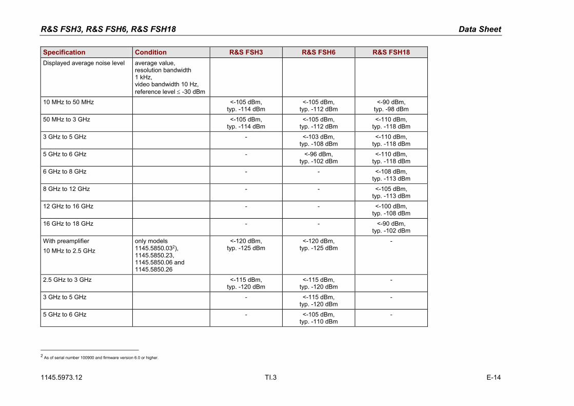
Specification Condition R&S FSH3 R&S FSH6 R&S FSH18Displayed average noise level average value,
resolution bandwidth1 kHz,video bandwidth 10 Hz,reference level ≤ -30 dBm
10 MHz to 50 MHz <-105 dBm,typ. -114 dBm
<-105 dBm,typ. -112 dBm
<-90 dBm,typ. -98 dBm
50 MHz to 3 GHz <-105 dBm,typ. -114 dBm
<-105 dBm,typ. -112 dBm
<-110 dBm,typ. -118 dBm
3 GHz to 5 GHz - <-103 dBm,typ. -108 dBm
<-110 dBm,typ. -118 dBm
5 GHz to 6 GHz - <-96 dBm,typ. -102 dBm
<-110 dBm,typ. -118 dBm
6 GHz to 8 GHz - - <-108 dBm,typ. -113 dBm
8 GHz to 12 GHz - - <-105 dBm,typ. -113 dBm
12 GHz to 16 GHz - - <-100 dBm,typ. -108 dBm
16 GHz to 18 GHz - - <-90 dBm,typ. -102 dBm
With preamplifier10 MHz to 2.5 GHz
only models1145.5850.032),1145.5850.23,1145.5850.06 and1145.5850.26
<-120 dBm,typ. -125 dBm
<-120 dBm,typ. -125 dBm
-
2.5 GHz to 3 GHz <-115 dBm,typ. -120 dBm
<-115 dBm,typ. -120 dBm
-
3 GHz to 5 GHz - <-115 dBm,typ. -120 dBm
-
5 GHz to 6 GHz - <-105 dBm,typ. -110 dBm
-
2 As of serial number 100900 and firmware version 6.0 or higher.

Data Sheet R&S FSH3, R&S FSH6, R&S FSH18
1145.5973.12 TI.4 E-14
Specification Condition R&S FSH3 R&S FSH6 R&S FSH18Inherent spurious reference level ≤ -20 dBm,
f > 30 MHz,RBW ≤100 kHz,S/N>10dB
<-80 dBm <-80 dBm <-80 dBm
Input related spuriousR&S FSH3 / FSH6Receive frequency
Up to 3 GHz3 GHz to 6 GHz
Receive frequency =signal frequency – 2.0156 GHz
mixer level ≤-40 dBmcarrier offset >1 MHz
signal frequency2 GHz to 3.2 GHz
-70 dBc (nominal)
55 dBc (nominal)
-70 dBc (nominal)-64 dBc (nominal)
55 dBc (nominal)
Input related spuriousR&S FSH18Receive frequency:10 MHz to 14 GHz
14 GHz to 18 GHz
Receive frequency =signal frequency – 3.9 GHzsignal frequency + 0.6 GHz to +1 GHzsignal frequency – 0.6 GHz to– 1 GHz
mixer level ≤-20 dBmcarrier offset >1MHzsignal frequency:10 MHz to 7.6 GHz7.6 GHz to 18 GHz10 MHz to 2.8 GHz2.8 GHz to 7.6 GHz7.6 GHz to 18 GHzsignal frequency:3.9 GHz to 18 GHz7.4 GHz to 7.7 GHz
7.8 GHz to 8.5 GHz
-60 dBc (nominal)-50 dBc (nominal)-50 dBc (nominal)-30 dBc (nominal)-50 dBc (nominal)
-40 dBc (nominal)-45 dBc(nominal)
-45 dBc(nominal)
2nd harmonicReceive frequency
Up to 6 GHz6 GHz to 9 GHz
mixer level -40 dBm
-60 dBc (nominal) -60 dBc (nominal) -60 dBc (nominal)-50 dBc (nominal)
Level displayReference level -80 to +20 dBm in steps of 1 dB
Display range 100 dB, 50 dB, 20 dB, 10 dB, linear
R&S FSH3, R&S FSH6, R&S FSH18 Data Sheet
1145.5973.12 TI.5 E-14
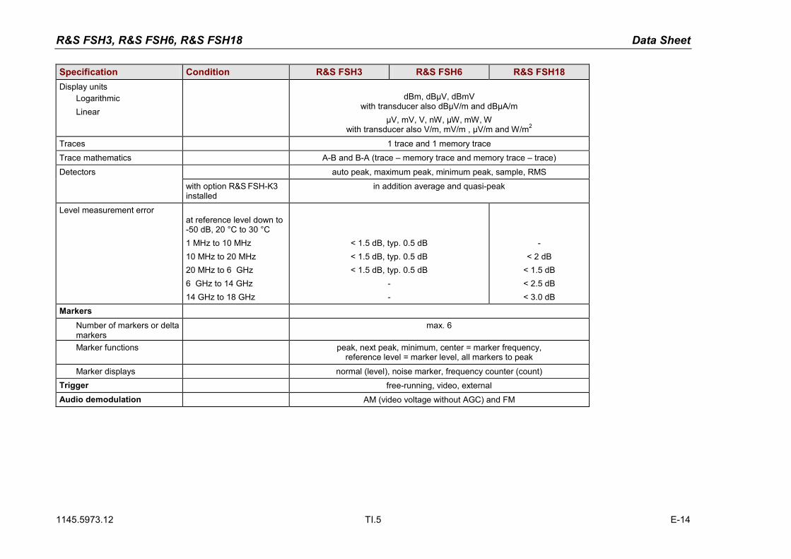
Specification Condition R&S FSH3 R&S FSH6 R&S FSH18Display units
LogarithmicLinear
dBm, dBµV, dBmVwith transducer also dBµV/m and dBµA/m
µV, mV, V, nW, µW, mW, Wwith transducer also V/m, mV/m , µV/m and W/m2
Traces 1 trace and 1 memory trace
Trace mathematics A-B and B-A (trace – memory trace and memory trace – trace)
Detectors auto peak, maximum peak, minimum peak, sample, RMS
with option R&S FSH-K3installed
in addition average and quasi-peak
Level measurement errorat reference level down to-50 dB, 20 °C to 30 °C1 MHz to 10 MHz10 MHz to 20 MHz20 MHz to 6 GHz6 GHz to 14 GHz14 GHz to 18 GHz
< 1.5 dB, typ. 0.5 dB< 1.5 dB, typ. 0.5 dB< 1.5 dB, typ. 0.5 dB
--
-< 2 dB
< 1.5 dB< 2.5 dB< 3.0 dB
MarkersNumber of markers or deltamarkers
max. 6
Marker functions peak, next peak, minimum, center = marker frequency,reference level = marker level, all markers to peak
Marker displays normal (level), noise marker, frequency counter (count)Trigger free-running, video, externalAudio demodulation AM (video voltage without AGC) and FM

Data Sheet R&S FSH3, R&S FSH6, R&S FSH18
1145.5973.12 TI.6 E-14
Specification Condition R&S FSH3 R&S FSH6 R&S FSH18InputsRF input N female
Input impedance 50 Ω
VSWR 10 MHz to 3 GHz3 GHz to 6 GHz6 GHz to 15 GHz15 GHz to 18 GHz
<1.5 nominal <1.5 nominal<1.5 nominal
<1.5 nominal<1.5 nominal<2 nominal<3 nominal
Trigger/external reference input BNC female, selectable
Trigger voltage TTL
Reference frequency 10 MHz
Required level from 50 Ω 10 dBm
OutputsAF output 3.5 mm mini jack
Output impedanceOpen-circuit voltage
100 Ωadjustable up to 1.5 V
Tracking generator only models 145.5850.13,1145.5850.23 und1145.5850.26
Frequency range 5 MHz to 3 GHz 5 MHz to 6 GHz -
Output level model 1145.5850.13model 1145.5850.23
model 1145.5850.26f < 3 GHzf > 3 GHz
-20 dBm (nominal)0 dBm / -20 dBm,
selectable
- 10 dBm (nominal)- 20 dBm (nominal)
-
Output impedance 50 Ω, nominal
InterfacesRS-232-C optical interface
Baud rate 1200, 2400, 9600, 19200, 38400, 57600, 115200 baud
Power sensor 7-contact female connector (type Binder 712)

R&S FSH3, R&S FSH6, R&S FSH18 Data Sheet
1145.5973.12 TI.7 E-14
AccessoriesPower Sensors R&S FSH-Z1 and R&S FSH-Z18Frequency range R&S FSH-Z1 10 MHz to 8 GHz
R&S FSH-Z18 10 MHz to 18 GHz
VSWR10 MHz to 30 MHz30 MHz to 2.4 GHz2.4 GHz to 8 GHz
8 GHz to 18 GHz
< 1.15< 1.13< 1.20<1.25
Maximum input power average powerpeak power(<10 µs, 1% duty cycle)
400 mW (+26 dBm)1 W (+30 dBm)
Measurement range 200 pW to 200 mW (-67 dBm to +23 dBm)
Signal weighting average power
Effect of harmonicsEffect of modulation
<0.5 % (0.02 dB) at harmonic ratio of 20 dB<1.5 % (0.07 dB) for continuous digital modulation
Absolute measurementuncertainty
sine signals,no zero offset
10 MHz to 8 GHz
8 GHz to 18 GHz
15 °C to 35 °C0 °C to 50 °C15 °C to 35 °C0 °C to 50 °C
<2.3 % (0.10 dB)<4.2 % (0.18 dB)<3.5 % (0.15 dB)<5.0 % (0.21 dB)
Zero offset after zeroing < 110 pW
Dimensions 48 mm x 31 mm x 170 mm, connecting cable 1.5 m
Weight < 0.3 kg

Data Sheet R&S FSH3, R&S FSH6, R&S FSH18
1145.5973.12 TI.8 E-14
Directional Power Sensor R&S FSH-Z14Frequency range 25 MHz to 1 GHz
Power measurement range 30 mW to 300 W
VSWR referenced to 50 Ω < 1.06
Power-handling capacity depending on temperatureand matching(see diagram below)
100 W to 1000 W
Insertion loss < 0.06 dB
Directivity > 30 dBAverage power
Power measurement rangeCW, FM, PM, FSK, GMSKModulated signals CF: ratio of peak envelope
power to average power
30 mW to 300 W30 mW to 300 W / CF
Measurement uncertainty
25 MHz to 40 MHz40 MHz to 1 GHz
sine signal,18 °C to 28 °C, no zerooffset
4.0 % of measured value (0.17 dB)3.2 % of measured value (0.14 dB)
Zero offset after zeroing ± 4 mW
Range of typical meas. errorwith modulation
FM, PM, FSK, GMSKAM (80 %)2 CW carriers with identicalpowerEDGE, TETRA
*) if standard is selectedon the R&S FSH
0 % of measured value (0 dB)
± 3 % of measured value (± 0.13 dB)
± 2 % of measured value (± 0.09 dB)
± 0.5 % of measured value (± 0.02 dB) *)
Temperature coefficient25 MHz to 40 MHz40 MHz to 1 GHz
0.40 %/K (0.017 dB/K)0.25 %/K (0.011 dB/K)

R&S FSH3, R&S FSH6, R&S FSH18 Data Sheet
1145.5973.12 TI.9 E-14
Directional Power Sensor R&S FSH-Z14Max. peak envelope power
Power measurement rangeVideo bandwidth 4 kHz
200 kHz600 kHz
0.4 W to 300 W1 W to 300 W2 W to 300 W
Measurement uncertainty 18°C to 28°C same as for average power plus effect of peak holdcircuit
Error limits of peak holdcircuit for burst signals
Duty cycle ≥ 0.1 andrepetition rate ≥ 100 / s
20/s≤ repetition rate <100/s0.001≤ duty cycle < 0.1
video bandwidth 4 kHz
200 kHz
600 kHz
± (3 % of measured value + 0.05 W) starting from aburst width of 200 µs
± (3 % of measured value + 0.20 W) starting from aburst width of 4 µs
± (7 % of measured value + 0.40 W) starting from aburst width of 2 µs
plus ± (1.6 % of measured value + 0.15 W)plus ± 0.10 W
Temperature coefficient25 MHz to 40 MHz40 MHz to 1 GHz
0.50 %/K (0.022 dB/K)0.35 %/K (0.015 dB/K)
Load matchingMatching measurement range
Return lossVSWR
0 dB to 23 dB> 1.15
Minimum forward power specs met from 0.4 W 0.06 W

Data Sheet R&S FSH3, R&S FSH6, R&S FSH18
1145.5973.12 TI.10 E-14
Directional Power Sensor R&S FSH-Z14Error limits for matchingmeasurements
Power-handling capacity
Dimensions 120 mm x 95 mm x 39 mm, connecting cable 1.5 m
Weight 0.65 kg

R&S FSH3, R&S FSH6, R&S FSH18 Data Sheet
1145.5973.12 TI.11 E-14
Directional Power Sensor R&S FSH-Z44Frequency range 200 MHz to 4 GHz
Power measurement range 30 mW to 300 W
VSWR referenced to 50 Ω200 MHz to 3 GHz3 GHz to 4 GHz
< 1.07< 1.12
Power-handling capacity depending on temperatureand matching(see diagram below)
120 W to 1000 W
Insertion loss200 MHz to 1.5 GHz1.5 GHz to 4 GHz
< 0.06 dB< 0.09 dB
Directivity200 MHz to 3 GHz3 GHz to 4 GHz
> 30 dB> 26 dB
Average powerPower measurement range
CW, FM, PM, FSK, GMSK3GPP W-CDMA,cdmaOne, cdma2000,DAB, DVB-TOther modulated signals CF: ratio of peak envelope
power to average power
30 mW to 300 W30 mW to 120 W
30 mW to 300 W / CF
Measurement uncertainty
200 MHz to 300 MHz300 MHz to 4 GHz
sine signal,18 °C to 28 °C, no zerooffset
4.0 % of measured value (0.17 dB)3.2 % of measured value (0.14 dB)

Data Sheet R&S FSH3, R&S FSH6, R&S FSH18
1145.5973.12 TI.12 E-14
Directional Power Sensor R&S FSH-Z44Zero offset after zeroing ± 4 mW
Range of typical measure-ment error with modulation
FM, PM, FSK, GMSKAM (80 %)2 CW carriers with identicalpower
π/4-DQPSKEDGEcdmaOne, DAB3GPP W-CDMA, cdma2000DVB-T
*) if standard is selectedon the R&S FSH
0 % of measured value (0 dB)
± 3 % of measured value (± 0.13 dB)
± 2 % of measured value (± 0.09 dB)
± 2 % of measured value (± 0.09 dB)
± 0.5 % of measured value (± 0.02 dB) *)
± 1 % of measured value (± 0.04 dB) *)
± 2 % of measured value (± 0.09 dB) *)
± 2 % of measured value (± 0.09 dB) *)
Temperature coefficient200 MHz to 300 MHz300 MHz to 4 GHz
0.40 %/K (0.017 dB/K)0.25 %/K (0.011 dB/K)
Max. peak envelope powerPower measurement range
DAB, DVB-T, cdmaOne,cdma2000, 3GPP W-CDMAOther signals atvideo bandwidth 4 kHz
200 kHz4 MHz
4 W to 300 W
0.4 W to 300 W1 W to 300 W2 W to 300 W
R&S FSH3, R&S FSH6, R&S FSH18 Data Sheet
1145.5973.12 TI.13 E-14
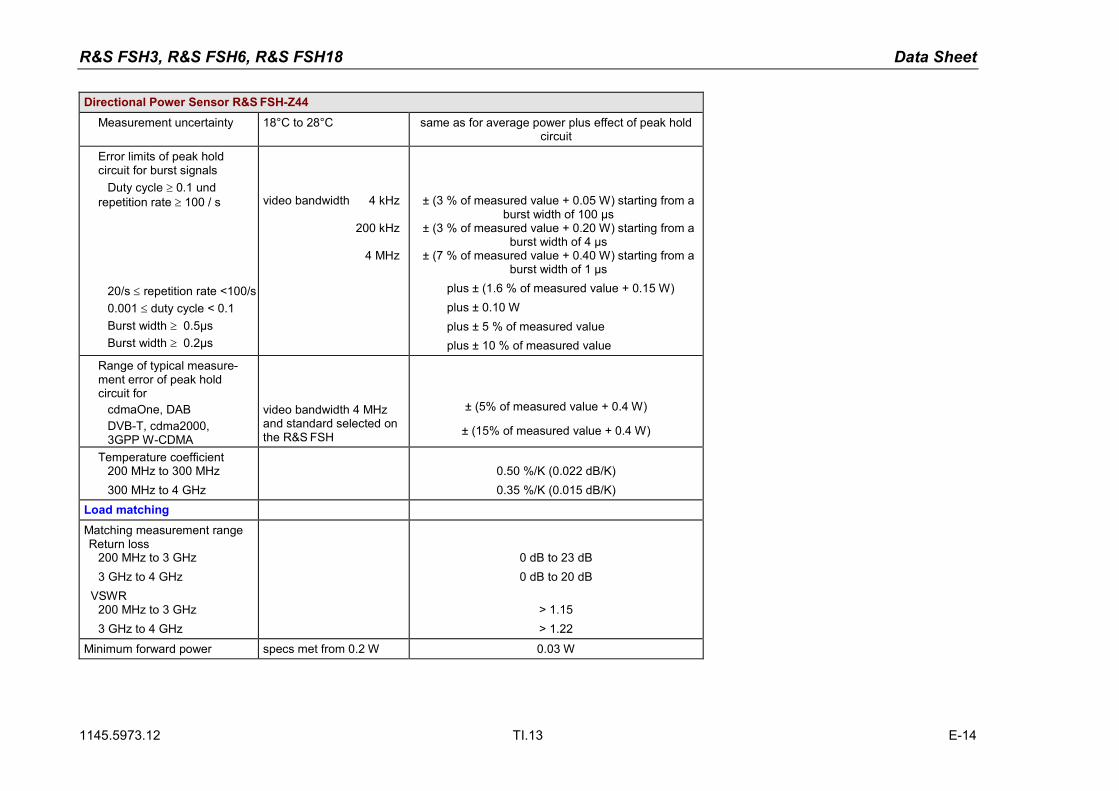
Directional Power Sensor R&S FSH-Z44Measurement uncertainty 18°C to 28°C same as for average power plus effect of peak hold
circuit
Error limits of peak holdcircuit for burst signals
Duty cycle ≥ 0.1 undrepetition rate ≥ 100 / s
20/s ≤ repetition rate <100/s0.001 ≤ duty cycle < 0.1Burst width ≥ 0.5µsBurst width ≥ 0.2µs
video bandwidth 4 kHz
200 kHz
4 MHz
± (3 % of measured value + 0.05 W) starting from aburst width of 100 µs
± (3 % of measured value + 0.20 W) starting from aburst width of 4 µs
± (7 % of measured value + 0.40 W) starting from aburst width of 1 µs
plus ± (1.6 % of measured value + 0.15 W)plus ± 0.10 Wplus ± 5 % of measured valueplus ± 10 % of measured value
Range of typical measure-ment error of peak holdcircuit for
cdmaOne, DABDVB-T, cdma2000,3GPP W-CDMA
video bandwidth 4 MHzand standard selected onthe R&S FSH
± (5% of measured value + 0.4 W)
± (15% of measured value + 0.4 W)
Temperature coefficient200 MHz to 300 MHz300 MHz to 4 GHz
0.50 %/K (0.022 dB/K)0.35 %/K (0.015 dB/K)
Load matchingMatching measurement rangeReturn loss
200 MHz to 3 GHz3 GHz to 4 GHz
VSWR200 MHz to 3 GHz3 GHz to 4 GHz
0 dB to 23 dB0 dB to 20 dB
> 1.15> 1.22
Minimum forward power specs met from 0.2 W 0.03 W

Data Sheet R&S FSH3, R&S FSH6, R&S FSH18
1145.5973.12 TI.14 E-14
Directional Power Sensor R&S FSH-Z44
Error limits for matchingmeasurements
dB0 5 10 15 20 25
Return loss
0.2 GHz to 3 GHz
3 GHz to 4 GHz
-4
-2
0
2
4
6
Mea
sure
men
t erro
r
dB
Power-handling capacityPEAK (max 10 ms), SWR < 3
AVG -10 °C to 35 °CSWR < 1.5
Forw
ard
powe
r
Frequency
0,2 0,4 0,7 1 2 3 4 GHz
100
200
400
600
800
1000
AVG -10 °C to 35 °CSWR < 3
AVG 35 °C to 50 °CSWR < 3
Dimensions 120 mm x 95 mm x 39 mm, connecting cable 1.5 m
Weight 0.65 kg

R&S FSH3, R&S FSH6, R&S FSH18 Data Sheet
1145.5973.12 TI.15 E-14
VSWR Bridge R&S FSH-Z2 / R&S FSH-Z3R&S FSH-Z2 R&S FSH-Z3
Frequency range 10 MHz to 3 GHz 10 MHz to 3 GHz
Impedance 50 Ω
VSWR bridge
Directivity10 MHz to 30 MHz30 MHz to 1 GHz1 GHz to 3 GHz3 GHz to 6 GHz
typ. 30 dBtyp. 30 dBtyp. 25 dB
-
typ. 16 dB> 20 dB, typ. 28 dB> 20 dB, typ. 28 dB> 16 dB, typ. 25 dB
Directivity, corrected2 MHz to 10 MHz10 MHz to 3 GHz3 GHz to 6 GHz
option R&S FSH-K2typ. 40 dBtyp. 43 dB
-
typ. 40 dBtyp. 40 dBtyp. 37 dB
Return loss at test port10 MHz to 50 MHz50 MHz to 3 GHz3 GHz to 6 GHz
20 dB, typ.20 dB, typ.
-
> 12 dB, typ. 18 dB> 16 dB, typ. 22 dB> 16 dB, typ. 22 dB
Return loss at test port,corrected
2 MHz to 3 GHz3 GHz to 6 GHz
option R&S FSH-K2
typ. 35 dB-
typ. 40 dBtyp. 37 dB
Insertion lossTest portBypass
typ. 9 dB-
typ. 9 dBtyp. 4 dB

Data Sheet R&S FSH3, R&S FSH6, R&S FSH18
1145.5973.12 TI.16 E-14
VSWR Bridge R&S FSH-Z2 / R&S FSH-Z3R&S FSH-Z2 R&S FSH-Z3
DC bias -
Max. input voltage - 50 V
Max. input current - 300 mA /600 mA *)
Type of connector - BNC femaleConnectorsGenerator input/RF output N male
Test port N female
Control interface 7-contact connector (type Binder)General dataPower consumption - 3 mW (nominal)
Dimensions (W x H x D) 169 mm x 116 mm x30 mm
149 mm x 144 mm x45 mm
Weight 485 g 620 gCalibration standards R&S FSH-Z29
R&S FSH-Z30/-Z31R&S FSH-Z28
Short/open N male
50 Ω load N male
Impedance 50 Ω
Return lossDC to 3 GHz3 GHz to 6 GHz
> 43 dB-
> 40 dB, typ. 46 dB> 37 dB, typ. 43 dB
Power-handling capacity 1 W 1 W
*) as of serial number 100500

R&S FSH3, R&S FSH6, R&S FSH18 Data Sheet
1145.5973.12 TI.17 E-14
Distance-to-Fault Measurement R&S FSH-B1(only with R&S FSH3 models 1145.5850.13, 1145.5850.23 and R&S FSH6 model 1145.5850.26)Display 301 pixels
Maximum resolution, distanceto fault
maximum zoom cable length/1023 pixels
Display rangeReturn lossVSWR
Reflection coefficientmRho
10, 5, 2, 1 dB/div, linear1 to 2 ,1 to 6, 1 to 10 und 1 to 20 with option
R&S FSH-K2 in addition1 to 1.2 and 1 to 1.5
0 to 1, 0 to 0.1, 0 to 0.01, 0 to 0.0010 to 100, 0 to 100, 0 to 10, 0 to 1
Cable length depending on cable loss 0 m to max. 1000 m
Maximum permissible spurioussignal
1st mixer 1 dB compression point typ. +10 dBmIF overload at reference level typ. +8 dB
Specification Condition R&S FSH3 R&S FSH6Transmission measurements (only with R&S FSH3 models 1145.5850.13, 1145.5850.23 and R&S FSH6model 1145.5850.26)Frequency range 5 MHz bis 3 GHz 5 MHz bis 6 GHz
Dynamic range10 MHz to 2.2 GHz
2.2 to 3 GHz
3 to 5 GHz
5 to 6 GHz
scalar modevector mode, optionR&S FSH-K2scalar modevector mode, optionR&S FSH-K2scalar modevector mode, optionR&S FSH-K2scalar modevector mode, optionR&S FSH-K2
typ. 60 dBtyp. 80 dB
typ. 50 dBtyp. 65 dB
--
--
typ. 80 dBtyp. 90 dB
typ. 70 dBtyp. 85 dB
typ. 40 dBtyp. 55 dB
typ. 35 dBtyp. 50 dB

Data Sheet R&S FSH3, R&S FSH6, R&S FSH18
1145.5973.12 TI.18 E-14
Specification Condition R&S FSH3 R&S FSH6Reflection measurements(only with R&S FSH3 model 1145.5850.13 or 1145.5850.23, R&S FSH6 model 1145.5850.26 andR&S FSH-Z2/-Z3)Frequency range 10 MHz to 3 GHz 10 MHz to 3 GHz
Display range of return loss 10, 20, 50, 100 dB, selectable
VSWR display range 1 to 2 , 1 to 6, 1 to 10 und 1 to 20, selectable,with option R&S FSH-K2 also 1 to 1.2 and 1 to 1.5
Display rangeReflection coefficientmRho
0 to 1, 0 to 0.1, 0 to 0.01, 0 to 0.0010 to 100, 0 to 100, 0 to 10, 0 to 1
Smith chart only with optionR&S FSH-K2
Marker formats:Reflection dB mag and phase
lin mag and phasereal and imag
Impedance R+jX(R+jX)/Z0
Admittance G+jB(G+jB)/Z0
Reference impedance Z0 10 mΩ to 10 kΩ
Zoom function expansion factor 2, 4, 8
Measurement uncertainty see diagrams

R&S FSH3, R&S FSH6, R&S FSH18 Data Sheet
1145.5973.12 TI.19 E-14
-3
-2
-1
0
1
2
3
0 2 4 6 8 10 12 14 16 18 20
Return Loss DUT / dB
Mea
sure
men
tU
ncer
tain
ty /
dB
Measurement uncertainty with scalarmeasurements
-3
-2
-1
0
1
2
3
0 5 10 15 20 25 30Return Loss DUT / dB
Mea
sure
men
tU
ncer
tain
ty /
dB
Measurement uncertainty with vectormeasurements (option R&S FSH-K2)
Specification Condition R&S FSH3 R&S FSH6Phase measurements (transmission, reflection)(only with R&S FSH3 models 1145.5850.13 or 1145.5850.23, R&S FSH6 1145.5850.26 and R&S FSH-K2)Frequency range
ReflectionTransmission
with R&S FSH-Z2/-Z3 10 MHz to 3 GHz5 MHz to 3 GHz
10 MHz to 6 GHz5 MHz to 6 GHz
Display range ± 180° (wrap)0° to 54360° (unwrap)
Group delay measurements(only with R&S FSH3 models 1145.5850.13 or 1145.5850.23, R&S FSH6 1145.5850.26 and R&S FSH-K2)Frequency range
ReflectionTransmission
with R&S FSH-Z2/-Z3 10 MHz to 3 GHz5 MHz to 3 GHz
10 MHz to 6 GHz5 MHz to 6 GHz
Aperture increments 1 to 300
Display range 10 ns, 20 ns, 50 ns, 100 ns, 200 ns, 500 ns,1000 ns, selectable

Data Sheet R&S FSH3, R&S FSH6, R&S FSH18
1145.5973.12 TI.20 E-14
Specification Condition R&S FSH3(only for model 1145.5850.23 as of serial
number 103500)3GPP FDD code domain power BTS/Node B measurement(only with R&S FSH-K4 1300.7633.02)
Frequency range 10 MHz to 3 GHz
Carrier frequency error (test case 6.3 in accordance with 3GPP 25.141)
Measurement range ±1 kHzMeasurement uncertainty S/N > 30 dB < 50 Hz + ∆fref
1) (σ = 20 Hz)
Total power S/N > 30 dB (test case 6.2.1 in accordance with 3GPP 25.141)
Measurement range frequency > 1 MHz20 °C to 30 °C
-60 dBm < Ptotal < 20 dBm
Measurement uncertainty -40 dBm < Ptotal < 20 dBmPREF_LEV -30dB < Ptotal <PREF_LEV+3dB
± 1.5 dB, typ. 0.5 dB
CPICH power S/N > 30 dB (test case 6.2.2 in accordance with 3GPP 25.141)
Measurement range -40 dBm < Ptotal < 20 dBm Ptotal -20 dB < PCPICH < Ptotal
Measurement uncertainty - Ptotal -20 dBm < PCPICH < Ptotal ± 1.5 dB, typ. 0.5 dB
P-CCPCH power S/N > 30 dBMeasurement range -40 dBm < Ptotal < 20 dBm Ptotal -40 dB < PPCCPCH < Ptotal
Measurement uncertainty Ptotal -20 dBm < PPCCPCH < Ptotal ± 1.5 dB, typ. 0.5 dB
PSCH/SSCH power S/N > 30 dBMeasurement range -40 dBm < Ptotal < 20 dBm Ptotal -30 dB < PSCH < Ptotal
Measurement uncertainty Ptotal -20 dBm < PPSCH < Ptotal ± 2.5 dB, typ. 1.5 dB
Symbol EVMMeasurement range 3% < EVMsymbol < 25%Measurement uncertainty 3% < EVMsymbol < 10% ± 2.5% typ.
10% < EVMsymbol < 20% ± 3.0% typ.Residual EVMsymbol 3% typ.

R&S FSH3, R&S FSH6, R&S FSH18 Data Sheet
1145.5973.12 TI.21 E-14
Specification Condition R&S FSH33GPP FDD scrambling code detection
Frequency range ± 1 kHz 10 MHz to 3 GHz
Single scrambling codedetection
Calculation time 24 s
CPICH EC / I0 > -18 dB 2)
Multiple scrambling codedetection
Max. number ofscrambling codes
8
Calculation time 57 sCPICH EC / I0 > -21 dB 2)
CPICH powerMeasurement uncertainty
-40 dBm < Ptotal < 20 dBm ± 4.2 dB
1) ∆fref = uncertainty of reference frequency source.2) Probability of detection >50% with test model 1.16 in accordance with 3GPP TS 25.141 test specifications.

Data Sheet R&S FSH3, R&S FSH6, R&S FSH18
1145.5973.12 TI.22 E-14
General dataDisplay 14 cm (5.7") LC color display
Resolution 320 x 240 pixelsMemory
Settings and tracesCMOS RAM100
Environmental conditionsTemperature
Operating temperature rangeR&S FSH powered from internal batteryR&S FSH powered from AC power supply
0°C to 50 °C0°C to 40 °C
Storage temperature range -20°C to +60 °CBattery charging mode 0 °C to 40 °C
Climatic conditionsRelative humidity 95 % at 40 °C (IEC60068)
IP class of protection 51
Mechanical resistance
Vibration, sinusoidal complies with EN 60068-2-1, EN61010-15 Hz to 55 Hz: max. 2 g, 55 Hz to 150 Hz: 0.5 g constant,12 minutes per axis
Vibration, random complies with EN60068-2-6410 Hz to 500 Hz, 1.9 g, 30 minutes per axis
Shock complies with EN 60068-2-2740 g shock spectrum
RFI suppression complies with EMC directive of EU (89/336/EEC)and German EMC legislation
Immunity to radiated interferenceLevel display at 10 V/m (reference level ≤ -10 dBm)
Input frequencyIFOther frequencies
10 V/m
< -75 dBm (nominal)< -85 dBm (nominal)< displayed noise level

R&S FSH3, R&S FSH6, R&S FSH18 Data Sheet
1145.5973.12 TI.23 E-14
Power supply
AC supply plug-in AC power supply (R&S FSH-Z33)100 V AC to 240 V AC, 50 Hz to 60 Hz, 400 mA
External DC voltage 15 V to 20 V
Internal battery NiMH battery (type Fluke BP190, R&S FSH-Z32)Battery voltage 6 V to 9 VOperating time with fully charged battery typ. 4 h with tracking generator off, typ. 3 h with
tracking generator on, typ. 3 h for R&S FSH18Battery charging time 4 h with instrument offLifetime 300 to 500 charging cycles
Power consumption typ. 7 W
Safety complies with EN 61010-1, UL 3111-1,CSA C22.2 No. 1010-1
Test mark VDE, GS, CSA, CSA-NRTL
Dimensions (W x H x D) 170 mm x 120 mm x 270 mm
Weight 2.5 kg
Order No.
Handheld Spectrum Analyzer R&S FSH3100 kHz to 3 GHz, with preamplifier
1145.5850.03
Handheld Spectrum Analyzer R&S FSH3100 kHz to 3 GHz, with tracking generator
1145.5850.13
Handheld Spectrum Analyzer R&S FSH3100 kHz to 3 GHz, with tracking generator andpreamplifier
1145.5850.23
Handheld Spectrum Analyzer R&S FSH6100 kHz to 6 GHz, with preamplifier
1145.5850.06
Handheld Spectrum Analyzer R&S FSH6100 kHz to 6 GHz, with tracking generator andpreamplifier
1145.5850.26
Handheld Spectrum Analyzer R&S FSH1810 MHz to 18 GHz
1145.5850.18

Data Sheet R&S FSH3, R&S FSH6, R&S FSH18
1145.5973.12 TI.24 E-14
Power supply
Accessories supplied external power supply, battery pack (built-in),RS-232-C optical cable, headphones, Quick Start manual,CD-ROM with Control Software R&S FSH View anddocumentation
OptionsDesignation Order No.
Distance-to-Fault Measurement for the R&S FSH(includes 1 m cable, R&S FSH-Z2 required)
R&S FSH-B1 1145.5750.02
Remote Control via RS-232-C for the R&S FSH R&S FSH-K1 1157.3458.02Vector Transmission and Reflection Measurementsfor the R&S FSH
R&S FSH-K2 1157.3387.02
Receiver Mode for the R&S FSH R&S FSH-K3 1157.3429.023GPP FDD Code Domain Power BTS/Node BMeasurement for the R&S FSH3 model 23 as ofserial number 103500
R&S FSH-K4 1300.7633.02
Optional accessories
Designation Order No.
Power Sensor for the R&S FSH, 10 MHz to 8 GHz R&S FSH-Z1 1155.4505.02
VSWR Bridge and Power Divider for the R&S FSH,10 MHz to 3 GHz (incl. calibration standards open,short, 50 Ω load)
R&S FSH-Z2 1145.5767.02
VSWR Bridge with DC Bias and Bypass Connectorfor the R&S FSH, 10 MHz to 6 GHz (incl. calibrationstandards open, short, 50 Ω load)
R&S FSH-Z3 1300.7756.02

R&S FSH3, R&S FSH6, R&S FSH18 Data Sheet
1145.5973.12 TI.25 E-14
Power supply
Optional accessories
Designation Order No.
Directional Power Sensor for the R&S FSH,25 MHz to 1 GHz
R&S FSH-Z14 1120.6001.02
Power Sensor for the R&S FSH, 10 MHz to 18 GHz R&S FSH-Z18 1165.1909.02
Directional Power Sensor for the R&S FSH,200 MHz to 4 GHz
R&S FSH-Z44 1165.2305.02
Matching Pad, 50/75 Ω, 0 Hz to 2700 MHz RAZ 0358.5714.02
Spare RF Cable (1 m),connectors N male/N female for R&S FSH-B1
R&S FSH-Z20 1145.5867.02
12 V Car Adapter for the R&S FSH R&S FSH-Z21 1145.5873.02
Serial/Parallel Converter for the R&S FSH R&S FSH-Z22 1145.5880.02
Carrying Bag for the R&S FSH R&S FSH-Z25 1145.5896.02
Transit Case for the R&S FSH R&S FSH-Z26 1300.7627.00
Spare Combined Short/Open and 50 Ω Load forVSWR and DTF calibration, DC to 6 GHz
R&S FSH-Z28 1300.7804.02
Combined Short/Open and 50 Ω Load for VSWRand DTF calibration, DC to 3 GHz
R&S FSH-Z29 1300.7504.02
Spare Short/Open Calibration Standard forR&S FSH-Z2 for VSWR calibration, DC to 3 GHz
R&S FSH-Z30 1145.5773.02
Spare 50 Ω Load Standard for R&S FSH-Z2 forVSWR and DTF calibration, DC to 3 GHz
R&S FSH-Z31 1145.5780.02
Spare Battery Pack for the R&S FSH R&S FSH-Z32 1145.5796.02
Spare AC Power Supply for the R&S FSH R&S FSH-Z33 1145.5809.02

Data Sheet R&S FSH3, R&S FSH6, R&S FSH18
1145.5973.12 TI.26 E-14
Power supply
Optional accessories
Designation Order No.
Spare RS-232-C Optical Cable R&S FSH-Z34 1145.5815.02
Spare CD-ROM with Control Software R&S FSHView and documentation
R&S FSH-Z35 1145.5821.02
Spare Headphones R&S FSH-Z36 1145.5838.02
Spare USB Optical Cable R&S FSH-Z37 1300.7733.02
Active Directional Antenna R&S HE-200 4050.3509.02Portable EMF Measurement System, 30 MHz to3 GHz, for the Handheld Spectrum AnalyzerR&S FSH
R&S TS-EMF 1158.9295.13
Near-Field Probe Set R&S HZ-15 1147.2736.02
Preamplifier for the R&S HZ-15 R&S HZ-16 1147.2720.02