techno-gram 002-2021
TRANSCRIPT

TECHNO-GRAM 002-2021
Page 1 Last Edit Date October 1, 2021
SUBJECT: Retaining Walls
PURPOSE: To improve engineering and construction
quality of retaining walls
SCOPE: This techno-gram applies to all retaining wall permits in Prince George’s County
Effective immediately, the Department of Permitting, Inspections and Enforcement (DPIE) will require the following considerations and procedures for retaining wall design, permitting and construction inspection. This applies to all development projects (residential, commercial, institutional, etcetera). This techno-gram does not apply to cantilevered retaining walls for basements, which are covered by the 2015 IBC, Chapter 18.
01. All retaining walls are required to comply with the County building and grading codes.
02. The height of a retaining wall is
measured from lowest ground elevation on the lower or bottom side of wall to the highest elevation on the top of the retaining wall structure, at any given cross section of the wall.
03. Building permits are required for
retaining walls taller than 2 feet. Issuance of a grading permit is not sufficient for construction of retaining walls higher than 2 feet.
04. Soil investigation is required at a minimum rate of one soil test boring per 100 linear ft of the retaining wall length.
05. Timber retaining walls are not allowed.
06. The required permitting sequence for retaining walls is: a) Apply for a grading permit b) Apply for retaining wall building permit c) Grading permit issuance d) Retaining wall building permit issuance e)(Maintenance Agreement?)

TECHNO-GRAM 002-2021
Page 2 Last Edit Date October 1, 2021
Note: If a rough or fine grading permit plan shows the retaining wall, then this grading permit is considered the supporting grading permit for said retaining wall.
07. Retaining wall building permits can be obtained by the Owner,
Developer, or Contractor. For anyone other than the owner to apply for a retaining wall permit, a letter of authorization shall be obtained from the owner.
08. In general, on residential developments, the height of retaining
wall shall be minimized preferably to less than 6 feet, for ease of maintenance. This also applies to the cumulative height of tiered retaining walls.
09. Retaining walls shall be located on common homeowner or business
park association parcels. Retaining walls shall not be located in public storm drain or stormwater management easements. Retaining walls shall not be located in the County public road right of way, with the exception of abutment walls for bridges.
10. For segmental retaining walls (SRW)including mechanically
stabilized earth walls (MSEW) higher than 2 feet, and other proprietary products, the applicant shall include in the submittal the manufacturer’s information and specifications, and a valid evaluation report from an approved listing agency, such as the International Code Council – Evaluation Service(https://icc-es.org/). The permittee shall submit an acceptance letter for the geotechnical aspects only of the wall design from the GER if the GER is not the wall designer.
11. Retaining walls taller than 6 feet are required to have a
permanent easement in front of and behind the wall. This requirement also applies to a series of tiered retaining walls, for which the cumulative height of all walls exceeds 6 feet. The easement shall not be less than 10 feet wide on the low side of the wall. On the high side of the wall, the easement shall contain the backfill reinforcement zone, including geogrids, tiebacks, anchors, and footings. The easement on the high side of the wall shall not be less than 10 feet wide. Prior to grading and retaining wall permit issuance, grading plans shall reflect retaining wall easements and the horizontal extent of geogrids, tiebacks, anchors, footings, and reinforcement zone. The following site elements are not permissible inside retaining wall easements: • buried utilities (except as noted below) • building additions
TECHNO-GRAM 002-2021
Page 3 Last Edit Date October 1, 2021
• porches • structures • pools • decks • stormwater management devices and storm drain pipes • trees
The following site elements are permissible inside retaining wall easements:
• Storm drain outfall pipe located perpendicular to the wall, if there is no alternative but to penetrate through the wall. In this case, the storm drain shall have a drop manhole on the high side of the wall, and the storm drain pipe under the footing of the retaining wall shall be encased in an outer pipe sleeve that is at least 12” larger in size than the conveying storm drain pipe.
• Storm drain inlets and pipes necessary to capture the swale immediately above the wall. These storm drain systems must be designed shallow enough to be built above the geogrid or tieback system (not deeper than 2 feet) THIS IS WHAT GOT US IN TROUBLE AT TANTALLON WITH THE WALL MOVEMENT AND SD PIPE RAPTURE.
• sheds* • fences* - in this case fence posts shall be located a
minimum of 3 feet from face of wall to accommodate overturning forces
• patios* • pergolas* • benches* • sidewalks* • trails* • signage* • landscaping* (excluding trees) • private roads and parking lots* - in this case, guardrails
and traffic barriers shall be provided and located between the wall and the roadway, a minimum of 3 feet from the face of wall.
Above features with asterisks (*) are only allowable within retaining wall easements if easement language obligates the owner/maintainer of these features to remove and replace these elements, as may be required for wall maintenance or reconstruction.

TECHNO-GRAM 002-2021
Page 4 Last Edit Date October 1, 2021
Where construction within the retaining wall easement or overlapping of easements is unavoidable, the applicant shall apply to DPIE for a waiver. DPIE may or may not approve such waivers, depending on the specific conditions of the project.
Retaining wall easements AND MAINTENANCE AGREEMENTS shall be recorded prior to issuance of the retaining wall building permit. Retaining wall easements shall specify maintenance responsibility to be borne by the Homeowner’s Association or Business Park Association. The easement shall restrict future construction of unacceptable elements listed herein.
12. Retaining wall permit plans shall comply with the PG-DPIE Building Plan Review Checklist requirements, which can be downloaded from the DPIE website. The plans shall show wall drainage systems and backfill soil behind the wall, filter fabric between the granular backfill and the adjacent soils, structural elements, and reinforcement type and size. Retaining walls shall be designed to meet the minimum factor of safety of 1.5 AGAINST SLIDING AND OVERTURNING.T Retaining wall permit documents shall show in site plan view, wall profile view, and wall sections the extent of backfill reinforcement material, tiebacks, anchors, soil nails, geogrid, filter fabric, etc. The design professionals (structural, civil, geotechnical) shall fully coordinate reinforced zones with all site features.
13. Retaining walls shall be located with the toe of the wall at
least 25 ft from creeks, streams and swales, as these locations have the potential for eroding and undermining retaining wall structures. The design engineer shall submit a scour analysis for streams and swales in close proximity to retaining walls. If the scour analysis requires, the retaining wall permit plans shall be designed with a foundation system capable of withstanding the scour (for example deep foundation system) and/or armoring of the stream, as required.

TECHNO-GRAM 002-2021
Page 5 Last Edit Date October 1, 2021
14. Segmental retaining walls (SRWs), including the leveling pads,
shall not be placed below the 100-year floodplain elevation, due to concerns with scour and migration of soil backfill.
15. For retaining wall building permits, a global stability analysis
shall be provided for:
• walls with cumulative height taller than 10 feet • walls with cumulative height taller than 6 ft and with back
slope steeper than 3 horizontal to 1 vertical • walls on or adjacent to unstable soils (such as over-
consolidated clay) • when deemed necessary by DPIE or the Geotechnical engineer of
record (GER)
The global stability analyses shall be signed and sealed by a licensed geotechnical engineer. The retaining wall calculations shall achieve a 1.5 minimum factor of safety for global stability. The global stability analysis also applies to a series of tiered retaining walls, for which the cumulative height of all walls exceeds the heights described above. In addition to structural review, walls listed above shall also be reviewed from Geotechnical perspective by an engineer with geotechnical expertise. WHAT ABOUT THE MIN DISTNACE OF A BUILDING WALL FROM THE 1.5 SLIP PLANE?
16. Retaining walls shall be drained by a system that includes:
• Perforated drainage pipes at the toe of the wall. Toe drain pipes shall be connected to a solid drain (storm drain) or discharge (daylight) to grade.
• An upright drainage layer behind the wall façade that ties into the toe drainage behind the wall bottom. This drainage layer can be made of gravel, or a prefabricated geocomposite if recommended by the design engineer.
• Filter fabric is required between the gravel and soil. • Perforated 2-inch minimum diameter PVC weep holes, thru the
wall, for the entire length of the wall, and at a maximum spacing of 20 feet, located at the toe of the wall.

TECHNO-GRAM 002-2021
Page 6 Last Edit Date October 1, 2021
17. Within the wall reinforced backfill zone and select backfill
zone, the upper soil layer shall consist of at least 4 inches of topsoil and 12 inches of impervious clay soil or an impermeable geomembrane below the topsoil. The purpose of this is to limit surface water infiltration into the backfill reinforcement zone and select backfill zone of the retaining wall.
18. To prevent surface storm water from flowing over the top of wall, a swale is required immediately behind the wall. The swale may be located at least 12 inches behind the high side of the wall, with a depth of at least 6 inches. The swale shall have 4 inches of topsoil at the surface and 12” of impervious clay soil or an impermeable geomembrane below the topsoil. Note: If the length of land adjacent to and perpendicular to the wall is negligible (for example less than 5 feet wide), such that surface sheet flow down the slope and towards the wall is minimal, then

TECHNO-GRAM 002-2021
Page 7 Last Edit Date October 1, 2021
the swale above the wall is not required. All concentrated flows shall be intercepted into a storm drain system and conveyed thru the wall.
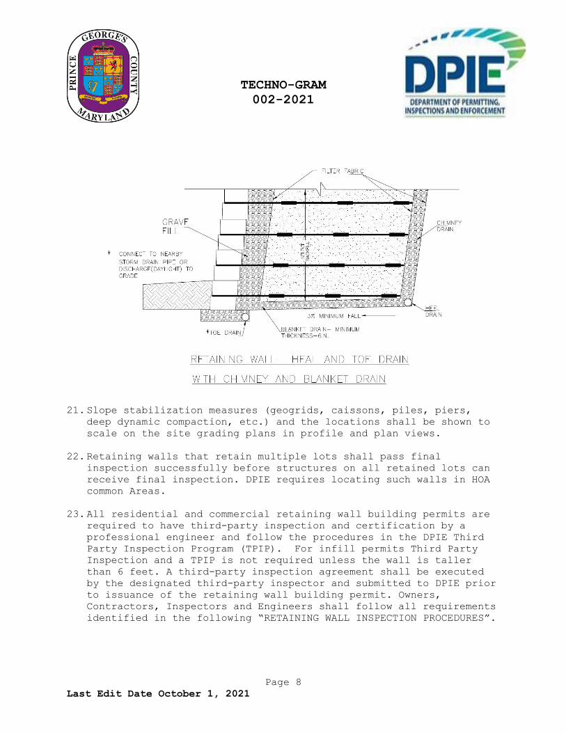
19. If the groundwater elevation is 2 feet or less below the retaining wall leveling pad or is expected to rise seasonally to the bottom of the leveling pad or higher, a blanket drain is required below the retaining wall, near the bottom of the leveling pad. Typical details for swales, blanket drains and chimney drains are included herein.
20. If an identified water source such as groundwater or springs are
located on the high side of a retaining wall, a drainage blanket and chimney drains (at least 6” thick) are required. The drainage blanket shall extend laterally from the wall to the chimney drain at a rising slope of 3%. The chimney drain shall rise to the elevation of the groundwater source, and shall have a heel drain pipe (minimum 4” diameter) at its bottom. Blanket and chimney drains are also required if surface drainage runoff or subsurface water may otherwise flow to the wall, which frequently comes from unconfirmed or unidentified water source. The blanket shall extend back from the wall to cover the entire easement or to reach the possible water source, whichever is shorter. The chimney height shall be 70% of the wall height (defined in #2 above) with a heel drain pipe at the location shown below.
TECHNO-GRAM 002-2021
Page 8 Last Edit Date October 1, 2021
21. Slope stabilization measures (geogrids, caissons, piles, piers,
deep dynamic compaction, etc.) and the locations shall be shown to scale on the site grading plans in profile and plan views.
22. Retaining walls that retain multiple lots shall pass final inspection successfully before structures on all retained lots can receive final inspection. DPIE requires locating such walls in HOA common Areas.
23. All residential and commercial retaining wall building permits are
required to have third-party inspection and certification by a professional engineer and follow the procedures in the DPIE Third Party Inspection Program (TPIP). For infill permits Third Party Inspection and a TPIP is not required unless the wall is taller than 6 feet. A third-party inspection agreement shall be executed by the designated third-party inspector and submitted to DPIE prior to issuance of the retaining wall building permit. Owners, Contractors, Inspectors and Engineers shall follow all requirements identified in the following “RETAINING WALL INSPECTION PROCEDURES”.

TECHNO-GRAM 002-2021
Page 9 Last Edit Date October 1, 2021
Retaining Wall Inspection Procedures
(New Construction) – Site / Permit(s): CG / CGU/ CGW / RG / RGW
This checklist should be used by Owners, Contractors, Inspectors and Engineers to implement quality control for retaining wall construction. Not only should the inspector review all aspects of the structural quality but also the quality of project construction, materials and workmanship. Colored photographs shall be taken on each workday to document the project from start to finish.
Retaining walls 2’ or less in height are exempt from permit and inspections.
Single/infill lot residential projects - retaining walls 2’ to 5’ in height require a permit and inspection by the County inspector. Walls greater than 5’ in height require a permit and third-party inspections program participation and approval.
Residential and Commercial development projects - retaining walls taller than 2’ require a permit and third-party inspections program participation and approval.
Height of a retaining wall is measured from lowest ground elevation on the lower or bottom side of wall to the highest elevation on the top of the retaining wall structure, at any given cross section of the wall.
Preconstruction Meeting for Retaining Wall Permits (Required):
Attendees:
• County Site and Building inspector(s) • Owner or their representative(s) • Contactor • Sub-contractor installing the retaining wall. • Geotechnical and Structural Engineers “Third party”
inspector(s)

TECHNO-GRAM 002-2021
Page 10 Last Edit Date October 1, 2021
Items needed:
• Approved Permit Plans - Approved grading permit and retaining wall building permit plans must be on site for inspector’s use.
• Copy of permit(s) – (Site, walls, accessory structures, etc.) Permit(s) must be issued and a copy on site for inspector’s use.
• County approved Geotechnical report • County approved Global Slope Stability Analysis Report • TPIP agreement
Superintendent / Contractor shall have upon request by the County building inspector:
• Original stamped set of approved permit plans • Copy of permit(s) • Third-party inspection field reports – inspector shall
submit the inspection results to the county building inspector within four (4) days after the inspection and at final approval
Note: All changes have been documented and noted on the construction drawings. Structural changes in design or installation must be re-submitted for permit approval by DPIE. (No exceptions) Statement of Third-Party Inspections:
Third-party Inspectors must not be affiliated with the respective Design Engineers for the same permitted work, to prevent firms or individuals from inspecting their own design work. For example, the third- party inspector must not be an individual employed by the same company, business, or firm that employs with the design Engineer for the same permitted work. Firms that serve as a construction contractor or installer must not be able to provide Third-Party Inspectors for the same project work.
Note: Review the TPIP agreement to verify that the structural design engineer and the structural inspector are from different firm / companies.
TECHNO-GRAM 002-2021
Page 11 Last Edit Date October 1, 2021
Daily Field Inspections Report Procedures:
A Geotechnical engineer and/or structural engineer or their representative(s) (field tech) must keep a daily log as to work performed and inspected each day with photographs.
Each field report shall contain the following:
1. Date/time of inspection 2. Affix Permit number for each inspection on the report. 3. Printed name of Inspector - (Performing the inspection) 4. License/certification number of Inspector - (Performing the
inspection)
5. Company name 6. Contact phone number 7. Type of inspection: (All reports must be specific as to the
nature of the inspection work performed each day as per approved plans.)
8. Inspection result (pass/fail) 9. Signature of the inspector 10.Photographs of wall installation with report documentation for each day of fieldwork.
Final Inspection Requests:
Final inspections shall be requested through Prince George’s County - AIRIS system: (301) 883-5390 and/or submitted online. Enter a contact phone number. The system will provide you with a confirmation number.
Items needed for final approval:
Submit Attachment #5 • Submit daily field report, photographs and testing
certifications Submit Attachment #6
• Submit a copy of the permit • Certification(s) must be signed and sealed. Original(s)
shall be submitted to the building inspector for approval. • Depending on the length of the wall this may need to be
completed in phases.

TECHNO-GRAM 002-2021
Page 12 Last Edit Date October 1, 2021
A separate attachment #6 is required for each phase A separate certification is required for every phase.
• A final attachment #6 is needed for completion of the permit\project.
The County site and building inspectors will review all documents. If the documents comply, the project will be issued final approval.
Note: Retaining wall must pass final inspection successfully before the structure(s) on any affected lot can receive a final inspection.
Retaining Wall Inspection Checklist:
The Owner/ Contractor shall hire a qualified professional for discipline-specific inspections and testing services.
Note: Inspection report(s) must be specific as to the nature of the work performed. Each daily field report must list material type, installation method and testing method with results of approved materials per DPIE-approved plans.
Site Survey: Check / initial
� ___ Locations and elevations of all stakes should match construction drawings.
� ___ Each base elevation change should have corresponding stake. � ___ Foundation soils shall match or exceed soil types and
strengths specified in the design plans. � ___ Backfill material shall match or exceed the material type and
strengths specified on DPIE-approved design plans. � ___ Slopes above and below wall shall not exceed those on DPIE
approved grading plans. � ___ Loading should not exceed those on DPIE approved design
plans. � ___ Groundwater\water table conditions shall match those shown on
DPIE-approved design plans.
TECHNO-GRAM 002-2021
Page 13 Last Edit Date October 1, 2021
Soil type & compaction of foundation bearing grades:
Check / initial � ___ The sub-grade soils meet the minimum requirements as by the
specified soil type approved. � ___ Site soils should not be frozen. � ___ Unsuitable sub-grade soils shall be removed and replaced
prior to wall construction. � ___ The replaced or disturbed subgrade soils must be compacted to
95% Standard Proctor Density.
Base leveling pad material and embedment depth:
Check / initial � ___ Gravel of base leveling pad is as specified in the wall
design plans or approved installation guidelines. � ___ The base leveling pad depth and width is in accordance with
approved installation guidelines. � ___ The compaction density meets the requirements of the
specifications approved. � ___ The surface of the base leveling pad is leveled in both
longitudinal and transverse dimensions. � ___ The location, elevation, and minimum embedment depth of the
leveling pad at each elevation change of the pad base match the construction drawings.
� ___ The base geo-fabrics are placed in accordance with their installation guidelines.
Concrete wall units and their installation:
Check / initial � ___ Manufacture certificate stating that all concrete block meets
manufacture design specifications � ___ All units are sound and free of cracks or other defects per
manufactures specifications � ___ The unit size, color, and dimension tolerances match those
specified on DPIE-approved plans. � ___ Clear crushed gravel should be filled into all unit voids. � ___ Unit voids should be filled no more than one (1) row of units
at a time.

TECHNO-GRAM 002-2021
Page 14 Last Edit Date October 1, 2021
Backfill material type and its installation:
Check / initial � ___ All unit connectors should be properly engaged. � ___ Soils shall be compacted at ± 2% of optimum moisture (not too
dry or too wet). � ___ Soils should be compacted in lifts 6-8 inches thick and to at
least 95% of the Standard Proctor maximum density. � ___ Backfill material behind segmental retaining walls (SRW)
shall be placed on flat geogrids and be flush with the top of the wall units.
� ___ Backfill material shall be placed and compacted to at least 95% Standard Proctor at the front or toe of wall to the full depth of the wall embedment specified on DPIE-approved wall plans.
� ___ Prior to its placement, backfill material type shall be approved by the Geotech on site or his representative. If it is different than those specified on the approved wall plans, design engineer and DPIE Site Road Plan Review’s approvals are required.
Reinforcement of backfill material and its installation: Check / initial
� ___ All reinforcements should be placed flat in the correct orientation.
� ___ Reinforcements should be placed on top of the proper row of wall units.
� ___ Reinforcements should be of correct length and tensile strength as shown on the approved wall design plans.
� ___ Reinforcement should be properly connected to the units. � ___ Reinforcement should be properly stretched before placing the
backfill material. � ___ Equipment should not be driven on the reinforcement directly. � ___ Reinforcement along curves, corners or other special
applications shall be placed per the design details or its manufacturer’s specification listed on DPIE-approved wall plans.
Draintile, weep holes - type/size: Check / initial
� ___ Drainage gravel should be clear crushed gravel with no fines per DPIE-approved wall plans.
TECHNO-GRAM 002-2021
Page 15 Last Edit Date October 1, 2021
� ___ Perforated drainage pipe (if needed) should be sloped properly and daylighted at proper intervals specified on DPIE-approved wall plans.
� ___ All drainage material must meet design specifications and certifications as per approved plans.
Geo-Fabrics:
Check / initial � ___ Geo-fabrics should be placed per their installation
guidelines where indicated on the approved wall plans.
Emphasized times for taking photos during construction:
Check / initial � ___ Completion of trench excavation for the Leveling Pad � ___ Leveling pad completion � ___ Completion of each course or row of wall blocks or units � ___ Completion of each compacted layer of backfill material � ___ Completion of each installed layer of backfill reinforcement
(geogrid) � ___ Geogrid around obstruction such as storm drain pipes,
structures\inlets, fence posts. � ___ Finished project
Above and below wall finished grading: Check / initial
� ___ Final grades should meet design plans in terms of height and tolerance
� ___ All grades, slope lengths and drainage swales should be in accordance with DPIE-approved grading plans.
� ___ At the end of the day ensure runoff of stormwater is away from MSE wall face or positive drainage flows away from the wall construction area.
Inspection reports numbered to , and testing reports numbered to , submitted prior to this final report form a basis for, and are to be considered an integral part of this final report.

TECHNO-GRAM 002-2021
Page 16 Last Edit Date October 1, 2021
To the best of my information, knowledge and belief, the inspections specified for this project, have been completed. In my professional opinion, the inspections have been found to be in compliance with County-approved construction documents and the Prince George’s County Building Code.
Respectfully submitted,
Affix P.E. Seal Below
Signature Date
Third-Party Inspector of Record - Printed Name
APPROVED BY:
________________________________,_ _____
Melinda Bolling, Director
October 14, 2021
Deputy Director