technological capability in design - loughborough … capability in design ... handicapped by the...
TRANSCRIPT

Loughborough UniversityInstitutional Repository
Technological capability indesign
This item was submitted to Loughborough University's Institutional Repositoryby the/an author.
Citation: NORMAN, E.W.L. and RILEY, J., 1988. Technological capabilityin design. Studies in Design Education Craft and Technology, 20 (3), pp. 154-162
Additional Information:
• This is an article from the serial, Studies in Design Education Craftand Technology [ c© Trentham Books Ltd]. It is also available at:https://ojs.lboro.ac.uk/ojs/index.php/SDEC/issue/archive
Metadata Record: https://dspace.lboro.ac.uk/2134/6470
Version: Published
Publisher: c© Trentham Books Ltd
Please cite the published version.

This item was submitted to Loughborough’s Institutional Repository (https://dspace.lboro.ac.uk/) by the author and is made available under the
following Creative Commons Licence conditions.
For the full text of this licence, please go to: http://creativecommons.org/licenses/by-nc-nd/2.5/

Technological Capability in Design
Eddie Norman and Joyce RileyLoughborough University
One of the cornerstones of the BAHonours degree programme for Designand Technology at Loughborough is thebelief that each student should develop apersonal capability to use technolgy.This capability, once developed, can beutilised in all the students' designprojects and gives and added dimensionto their creativity. A recent article byGeorge Hicks and HMI' puts forwardthe view that:
, ... as a society we depend on thosewith technological capability toproduce goods and services for ourbenefit, as well as to provide anetwork of systems that underpinother industries. Such people alsohave a responsibility to maintain anddevelop that capability continuouslyand to invent processes that open upnew possibilities'.
The products needed in a Westernnation will span the range from tablemats to supersonic aircraft. In 1977 theDesign Council evolved a model of theproduct design spectrum whichindicated the level of industrial andengineering design in each type ofproduct. 2 Figure I shows a slightlymodified representation of this productdesign spectrum indicating sampleproducts in each of three regions. Forthe products in region C the designconsiderations are mainly aesthetic.Industrial designers and craftsmen
using inherited and adapted skills ofcraft-based design and manufacturehave produced products for whichtechnology is secondary to otherconsiderations such as appearance,ergonomics and material suitability.
The products in region A are verydifferent; they are highly technical andrequire specialist engineers andtechnologists for many parts of thedesign. Technological considerationscan no longer be secondary. Thisinclusion of technological factors is nota new problem as is clearly illustrated bythe evolution of ships from timbersailing-craft to iron steamships.
, ... as Russe1l3 recounts, a greatnumber of the early experimentsduring the 1820s with large iron shipshad been disasters - ships whichoverturned on launching, shipscalamitously under-powered, shipswhose stability could be ensured onlyby adding extra floats or masses ofcement ballast. The design of thesevessels had been based on erroneousrules of thumb, and on principlessupposedly drawn from traditionalboat-building experience but whichwere as it turned out 'misknown, andmisbelieved, and mistaught' ... Thenew naval architecture will work byscience, calculation (and) 'headwork'
,4
SAMPLEPRODUCTS
Clearly it is not possible for a singleperson to undertake the design of one ofthese highly technical products alone.Instead, a group of experts cooperatingas a team will provide the best mix ofengineering skills, technology andaesthetics.
The central region B in Figure I iscomprised of comparatively small-scaleproducts for which aesthetic factors areimportant but also a knowledge of theappropriate technology is necessary.Products of this nature require bothtechnological and creative designconsiderations. However, becausedesigners have specialised in eitherEngineering or Industrial Design, oneof these factors had tended to becomesecondary to the other. Very often thissecondary design process is severelyhandicapped by the limitations placedon it by the primary process and acompromise solution is then the bestthat can be achieved.
A recent example of the necessity fortechnolgical capability in this type ofproduct design was highlighted in anarticle on the design of an adult tricyclewith either shopping carriers or childseats over the rear axle.5 A seriousaccident was nearly caused by the axlebeing sharply stepped down in twostages from 3;4" to Vl" as it entered thewheel bush. This produced a classic'notch' effect with high stressconcentrations. The rotation of the axleproduced cyclical loading which withthe 'notch' effect drastically reduced thelife of the axle. The material used fortheaxle was ENIA leaded steel whichmachines wdl but has very lowresistance to cyclical stress. A gooddesign would have had an t:ndurance lifeof about 10million cycles with a factorof safety of 3. However, the cumulativeeffect of the design faults was to reducethis to I million cycles, or about 2 yearsnormal use, with no safety factor toallow for road defects. Any suddenjarring would cause unusually highimpact stresses which would cause earlyfailure of the axle. Such failure at theoffside wheel bush causes the rider andchild passengers to be thrown out intothe traffic. A simple caluculation on thestresses induced in the shaft would havesaved the company involved theembarrassment and cost of appearingon BBC's Checkpoint programme, andhaving modifications enforced by the

Ministry of Transport's Vehicle SafetyDivision.
Products such as the adult tricyclewould obviously benefit by having adesigner capable of integrating thescienti fic and artistic aspects of design.The segregation of these two culturesand the understanding from a very earlyage that an individual is either artistic orscient ific makes this process ofintegration a very di fficult task. Anearly exponent of radical change ineducational methods towardsintegration was A.N. Whitehead.6 Morerecently the Royal Society of Arts indi fferent statements has both echoed thecriticism of an education that givesspecialist knowledge but no personalcapability and highlighted the problemsthat the cultural divide and itsperpetuation present to individuals andsociety.?
Higher Education has recognised thatcourses can be developed which willbridge the gap between the two cultures,
combining creative flair with atechnological and personal capability.The Royal College of Art's IndustrialDesign School, in conjunction withImperial College, introduced a newcourse 'Industrial Design Engineering'in 1980.8 This is a two year postgraduatecourse leading to a Masters degree inDesign. The course recruits a smallnumber of students and is intended toprovide a boost to British Industry,producing a superior science-baseddesigner with Industrial Design skillscapable of bridging the gap betweenEngineering Design and IndustrialDesignY From an initial intake of 4students, the 'Industrial DesignEngineering' course has steadily grownto a current intake of 16.This newdesign philosophy has also been pursuedby Cranfield Institute of Technology,who together with Leicester Polytechnicnow offer a Masters degree in ProductDesign.
At about the same time as the RCAinitiative, Loughborough's CreativeDesign Department decided thattechnical capability should and could beintegrated with design at undergraduatelevel, with similar aims and ideals to theRCA postgraduate course, and thattherefore 'Design and Technology' was amore appropriate title for thedepartment. This idea has beengenerally gaining ground, with an'I ndustriaI Design (Engineering)' courseat Brunel University and more recentlythe 'Product Design Engineering' coursebeing launched by the Department ofMechanical Engineering at theUniversity of Glasgow in partnershipwith the Glasgow School of Art. All ofthese undergraduate courses areendeavouring to create a completelyrounded designer with a good, solidunderstanding of the scientificprinciples and their mathematicalapplication as well as artistic andcreative sensibilities.
Statics An understanding of static forceforce systems and structures isgiven including:-Coplanar force systems, equilibriumand stability.Framework loading and internal forces.Beam and strut theory, Shear force,bending moment, internal stresses,sti ffness, and deflection.Design of tension and shear connections.Mathematical modelling of products.
Dynamics Linear and angular motionand their effect on mechanicalsystems are examined including:-Newton's laws of motion.Gearing, torque and moment ofinertia.Momentum, work, power and energyof various systems, efficiency,power transmission and matching torequirements.Project such as hill-climb or longdistance vehicle to incorporate many of the staticsand dynamics concepts gained so far.
Electronic Systems and Circuit TheoryAn investigation of electronic systems,their components and simple circuittheory is conducted. The work alsoincludes:-The use of instruments.Introduction to integrated circuits.Project which necessitates the design,assembly and evaluation of a printedcircuit board.
Devices and Components Study of commoncomponents and how they can be used incircuit design including:Electrical energy and power.Diode characteristics and logic.Zener stabilisation.Introduction to alternating currentand its rectification.Use of a transformer.Simple transistor theory andapplications.
TERM 3 Fluids Simple hydrostatic and fluiddynamic theory is investigated. Thestability of objects in a fluid mediumis explored and the principles of windand water power examined.
Studies in Design Education Craft and Technology Volume 20 Number 3Summer /988
Design Study This term isdevoted topower supply design whichnecessitates the consolidation andapplication of all the work to date.

Introducing technological issues tostudents taking design degrees is not,however, a straightforward matter, andrequires careful consideration ofappropriate issues and approaches. It isnecessary for students to be motivatedby seeing' the relevance of technology todesign and in this way fairly complexissues can be understood andincorporated into their work.
George Hicks, in a recent paper,described technology thus:-
'Technology is a creative anddisciplined activity informed by aknowledge of energy and control, ofmaterials, of methods ofmanufacture and it is supported bymany concepts and skills butparticularly those derived frommathematics and science. It is guidedby the values and attitudes of societyand is directed toward themaintenance and improvement ofhuman well-being'. I
Most new entrants to the degreeprogramme want to combine a creativeflair with the application of scienti ficknowledge but, as they have rarely hadthis opportunity previously, the firstyear of the degree programme has beendesigned to provide the foundation of abreadth of skills in Design andTechnology. One of the five mainmodules of study in Year I is 'ThePhysical Basis of Technology' for whichthe minimum requirement is theequivalent of GCSE Mathematics andScience. Students who arrive with 'A'level Maths and Physics have rarelylearnt to apply their theoretical
. knowledge and consequently theapplications of technology to design isthe key feature of this work. Thestudents who arrive with only GCSElevel Maths and Science haveconsiderable work to do to grasp theessential theories and application oftechnology but, if they are motivatedand see its relevance, they can do just aswell as those arriving with 'A'levelPhysics or Technology. 'The PhysicalBasis of Technology' module comprisesthe study of Mechanics and Electronicsby a lecture programme and laboratoryinvestigations to facilitate theunderstanding and implementation ofthe fundamental concepts and theappreciation of their apPlications. TableI gives an indication of the technologycontent of the Year I module.
The technological capabilitydeveloped in Year I continues in the'Technology in Design' core module inYear 2. This is a compulsory modulewhich combines a computing coursewith the study of systems andinstrumentation, pneumatics andcomputer control. In the systems andinstrumentation part of the module,students examine technological systemsof different kinds. The pneumaticssection of the module teaches usefullogic and low cost automationtechniques. In the computer controlelement of the module students learnhow to interface and control differentsystems using a microcomputer. Allstudents undertake a minor project toconsolidate each element of the module.In the final term they then undertake amajor group feasibility study whichintegrates the ideas from each area ofthe course together with groupmanagement skills.
In Year 2 the students also have anoption to study mechanical andelectronic technology in greater depth asa major area of study. Components ofMechanical, Digital and AnalogueSystems are studied in the context ofdesign. In Year 3 the 'Technology inDesign' option continues and extendsthe knowledge of technology alreadygained by the major technology studentsin Year 2, and seeks to develop asystematic approach to engineeringdesign.
The skills gamed in the compulsory,Year 3 'Design Practice' course,combined with the technology skills, areput to the test when the third yearstudents undertake a minor and a majordesign project often linked withIndustry. It has been a great challenge toour Major Technology students to beresponsible for technological projectslinked with industries where the designand engineering departments aretraditionally distinct. Third yearstudents have been involved inprofessional-based projects with suchclients as Austin Rover, Newman TonksEngineering Ltd., Vickers Medical PLC,Leicester Royal Infirmary and RollsRoyce and Associates. One such projectwas a new stering wheel designundertaken by a group of students forLotus Cars. At the outset of the projectthe company was not convinced that anindividual could encompass the highly
sophisticated technical and aestheticrequirements of the design, but havesince been very impressed by the workthat has been produced. An example ofthis work is given later in this article.
Another benefit that some of theseclients had not previously appreciated isthe ability of our students to help thecompany's two design factions tocommunicate effectively with eachother. This is one area that the RoyalCollege of Arts's initiative wished tocater for and there is no doubt that atechnically capable product designerworking as part of a team on largerproducts is of great benefit. From theexperience of our past and presentstudents in industry it is clear thattechnological capability is aconsiderable asset to a designer. Thechallenges they meet are great but therewards are much greater.
Examples of Undergraduate TechnologyCoursework and ProjectsThe examples which follow illustrate themeaning attributed to a personaltechnological capability forundergraduate de~igners taking theDesign and Technology degrees.Examples have been chosen from workdone by each of the three year groupsand they illustrate the hoped-forprogression from the analysis of existingproducts through feasibility studies andon to the analysis at the design stage oforiginal concepts.
Year IStatics The most significant issue whichstudents must understand is thedistinction between designing forstiffness and designing for strength. Fora beam these are represented by theformulae shown in Table 2. Thesemathematical models allow appropriatebeam dimensions to be calculated. Themost common example - that of abookshelf - is considered in a lecture.Strength calculations will typically yieldthickness for wooden shelves of6-lOmm. Students quickly realise theproblem, namely that if only strengthcriteria were applied the bookshelveswould be highly curved. If a reasonablefigure for the acceptable deflectionschosen (say Imm) then stiffnesscalculations will yield the thicknesses of15-20mm which is a more typical shelfdepth. Similarly, strength calculations

TABLE 2 Designing a Cantilever forStiffness and Strength
Mathematical8 = L 13
Model3EI
where 8 is the deflection at point IL is the loadE is the modulus of elasticityI is the second moment of area
Designer specifiesi) the load to be supported and its
positionii) the materialiii) the acceptable deflection
M = a-yy
where M is the bending momentI is the second moment of areaa isthestressatheightyy is the distance from the neutralaxis
Designer specifiesi) the load to be supported and its
positionii) the material
of the frame section for G-cramps, asindicated in Fig. 2, will yield a mild steelsection size of the order of 5xlOmm.This section size would not fail becausethe stress level would be limited toaround 200N/mm2, but unduedeflections would make it unfit for itspurpose. Gccramp frames are designedfor stiffness.
Designing for stiffness is not howeveralways about keeping deflections low-it is about controlling the deflections tobe the magnitude you require. Considerthe child-proof lock shown in Fig. 3. Itmust be possible for an adult to open thelock fairly easily, but for a child to haveconsiderable difficulty doing so. A forceof about ION is therefore a suitabledesign value to calculate the cross-section of the catch which will deflect
L
and open the lock under adult pressure.The length of the catch, e, is taken as50mm; its maximum deflection, 8, as7mm; and the Modulus of Elasticity, E,as 200N/mm2, which is typical of manyplastics. The deflection formula thengives:
I = Le3 = lOx 503 = 30mm4
3E8 3 x 2000 x 7
For a rectangular section1= bd3
12where b is the breadth and d is the depth.If b is taken as 6mm then
bd3
12 = 30.·.d3 = 60andd = 4mm
The section sizes of typical productswill be found to be approximately 6 x4mm. It should be emphasised thatwhen dimensions have been establishedgiving the appropriate stiffness themaximum stress level also needs to bechecked.
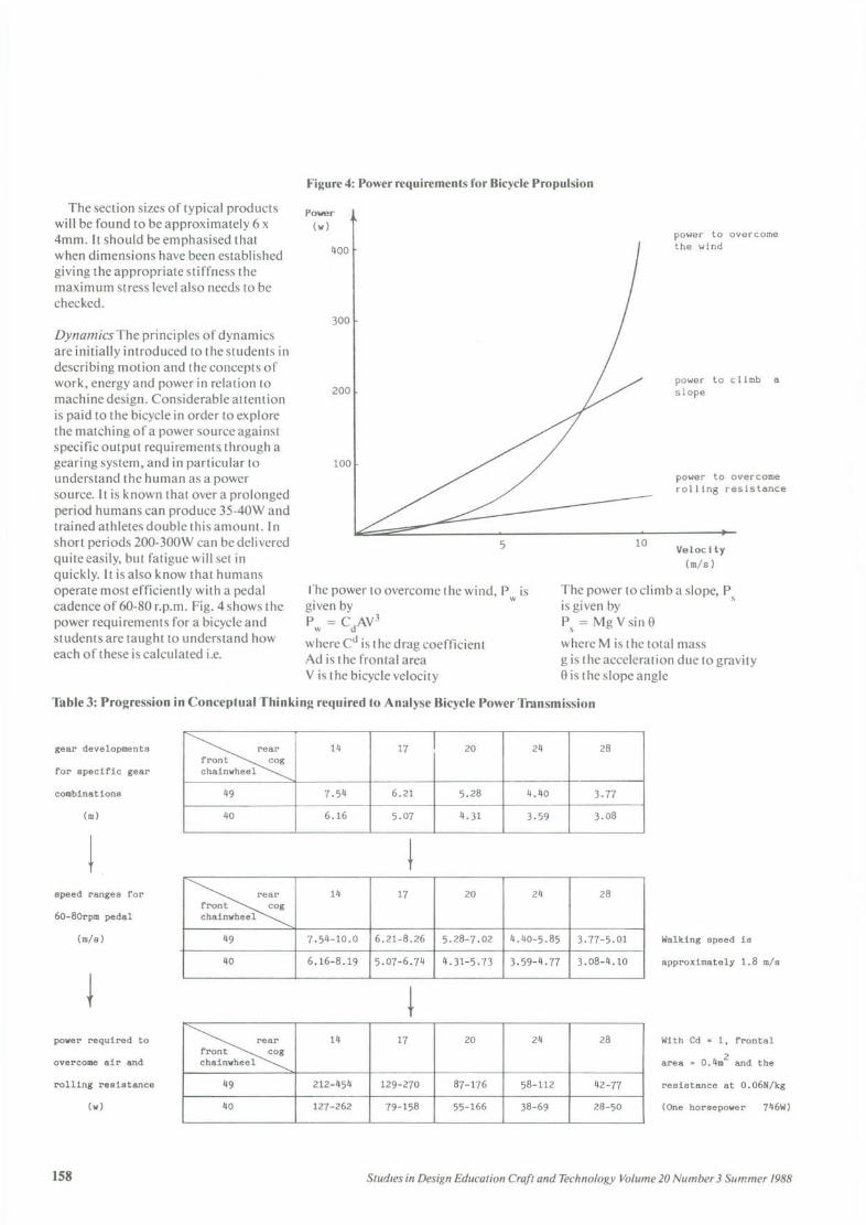
Dynamics The principles of dynamicsare initially introduced to the students indescribing motion and the concepts ofwork, energy and power in relation tomachine design. Considerable attentionis paid to the bicycle in order to explorethe matching of a power source againstspecific output requirement& through agearing system, and in particular tounderstand the human as a powersource. It is known that over a prolongedperiod humans can produce 35-40W andtrained athletes double this amount. Inshort periods 200-300W can be deliveredquite easily, but fatigue will set inquickly. It is also know that humansoperate most efficiently with a pedalcadence of 60-80 r.p.m. Fig. 4 shows thepower requirements for a bicycle andstudents are taught to understand howeach of these is calculated i.e.
Power(w)
rhe power to overcome the wind, P is~~n~ wP = C Ay3w d
where Cd is the drag coefficientAd is the frontal areaY is the bicycle velocity
power to climb aslope
power to overcomeroiling resistance
Velocity(m/s)
The power to climb a slope, p.is given by S
Ps = Mg Y sin ewhere M is the total massg is the acceleration due to gravitye is the slope angle
~
14 17 20 24 28front cogchainwheel
49 7.54 6.21 5.28 4.40 3.7740 6.16 5.07 4.31 3.59 3.08
~
14 17 20 24 28front cogchainwheel
49 7.54-10.0 6.21-8.26 5.28-7.02 4.40-5.85 3.77-5.0140 6.16-8.19 5.07-6.74 4.31-5.73 3.59-4.77 3.08-4.10
~
14 17 20 24 28front cogchainwheel
49 212-454 129-270 87-176 58-112 42-7740 127-262 79-158 55-166 38-69 28-50
With Cd = 1, frontal
area = 0.4m2 and the

Figure 5: Design Exam - GardenShredder
The power to overcome the rollingresistance, PR
is given by P R = MRVwhere R is the rolling resistance
These formulae allow the total outputpower required for any outputconditions to be calculated. Table 3shows the progression in conceptualthinking required to analyse the powertransmission for a bicycle. Studentsmust begin by understanding that fordifferent gear combinations the bicyclemoves forward di fferent distances forone complete revolution of the pedals.This distance is known as the geardevelopment. For a pedal speed range of60-80 r.p.m. this will result in bicyclespeed ranges given by:V =~xgd m/s
60where N is the pedal cadence in r.p.m.and gd is the gear development in m.
When travelling on the flat, powerwill be required to overcome the rollingand air resistance, and these powerrequirements are shown at the end ofTable 3. At this point it is possible toconsider the matching problem for inputand output power. If the rider meets a Iin 40 slope the power required to go up itat di fferent speeds is known. If the limiton the human power output is known,say WOW, then by looking at Fig. 4 andTable 3 the required gear combination(40/28 giving approximately 3m/s) canbe found. Such an analysis shows howbicycle power transmission design hasevolved in order to provide the rider withthe opportunity to match the power theyare prepared to deliver against theoutput requirements.
Once students have understood theseprinciples they can be applied to avariety of problems. In Third Worldareas the human is often the bestavailable power supply, and machinesfor raising water, grinding cereals,transporting passengers and otherloads, or charging batteries could all beanalysed. Equally, pedal-poweredgarden equipment for our own societymight well have advantages, e.g.lawnmowers or the garden shredder setas a problem in third year Design Exam.
I! .i/
~t . I
\
~\
controllable time intervals - areillustrated in Table 4. Students clearlyneed to be able to perform the simplecalculation associated with themathematical model, but the moredifficult task is seeing how the devicecan be used to solve a particularproblem. For a straightforward timingcircuit, say for giving a visible indicationof an appropriate exposure time in adarkroom, key questions might be:- how is a trigger signal to be producedfor the monos table circuit?or
Table 4: Basic timing functions available with a 555 Timer
Fig. 5 shows how one student thoughtthe problem might be tackled.
The 555 timerThe 555 integrated circuit can be madeto perform a number of timingfunctions by altering its externalconnections. The two basic modes ofoperation - monostable, where avoltage output is produced which goesoff after a controllable delay and,astable, where the output switchesbetween high and low output levels at
trigger
\{(~-~-3 I
Outputsignal VO"'U===L Vol"
I_._t,--~.I Time

- how can the termination of thevoltage output be made to produce avisible signal?
Fig. 6 shows how a suitable triggervoltage can be produced. With theswitch open no current is flowing andtherefore the voltage at point A is equalto the supply voltage. When the swi tch isclosed there is effectively a brief short-circuit which will give the trigger signalrequired.
For the voltage drop to trigger avisible device the circuit must be made to'sink' (rather than 'source') a current .through an indicating device as shown In
Figure 6: Obtaining a Trigger Voltage forthe 555 IC
push tomake
to 555»
Fig. 7. Whilst Vout is high, no currentwill flow through the LED. When VOUI
goes low the LED will light up. Theastable circuit can be used to producealternating signals to drive an audibledevice and more advanced studentsmight be asked to consider how anaudible indication of exposure timecould be produced.
Figure 7: The 555 IC acting as a currentsink
wheatstonebridge V.
I~dt~t .s rain
~
displaydevice
Whatever the project, the studentsneed to gain confidence in deciding on astrategy, using the mathematical modelsto predict performance, buildingphysical models using breadboard or akit to verify it, and then finally layingout and manufacturing a printed circuitboard on which to solder thecomponents. The final stage of faultfinding in the completed board is also akey skill which needs to be developed.
mechanical configuration. Fig. 8 showsthe kind of electromechanical systemwhich will need to be considered. Fromdatasheets it can quickly be establishedthat:V = V .0.£out _5
4where V is the bridge output voltage
OUI
V is the supply voltageso is the gauge factorand £ is the strainHence, as typical values for Vsand 0 are12V and 2.1V = 12x2.le = 6.3£
out -4
For steel at half its yield stress thestrain is approximately 0.002 and hencethe corresponding bridge output voltagewould be 12.5V. If this corresponded tothe 2.5kg load then each 5g correspondsto 12.5 x _5_ or 0.025mV
2500The students must establish the size ofbeam to give this strain level for the2.5kg load (using M = ~and then (J =
I Y
Year 2Instrumental SystemsStude;ts are introduced to the use of theWheatstone Bridge as a resistance-to-voltage converter and this is used withlight dependent resistors (LOR's) todetect changes in light intensity,thermistors to detect changes in heatand strain gauges to detect changes inloading. Changes in light intensity areused in many systems, e.g. to detectburglars, track the sun, indicatedaybreak, and switch on artificial lights.Changes in heat intensity are oftenmeasured by thermistors inenvironmental temperature controlsystems. Strain gauges are alsocommonly used, for example, in gripstrength measuring devices or weighingmachines, and a project such as this isoften set to the students. The followingproblem arose originally because of thework done within the Department inrelation to Perinatal Care Units with Dr.D.A. Ducker at All Saints' Hospital,Chatham.
'Examine the feasibility of weighinga baby of between 0.5 and 2.5kg to anaccuracy of 5g'
Monitoring the weight of a prematurebaby is crucial in giving early warning ofdifficulties. Assessing this feasibilitydepends on being able to consider boththe electrical output and a suitable
Studies in Design Education Craft and Technology Volume 20 Number 3 Summer 1988
whilst ensuring that it is large enough tomount the strain gauge and then go onto consider whether 0.025mV can bereliably detected to give the requiredaccuracy. I f not, how can a larger outputbe obtained?
Group feasibility studiesPower exercises machineFig. 9 shows a schematic diagram of ~powered exercise machine. I f the belt IS
not powered, then it is rather likerunning on sand. In order to simulateroad running it is necessary to acceleratethe belt up to running speed. In order tosimulate di fferent routes it is alsodesirable to vary the belt load for set
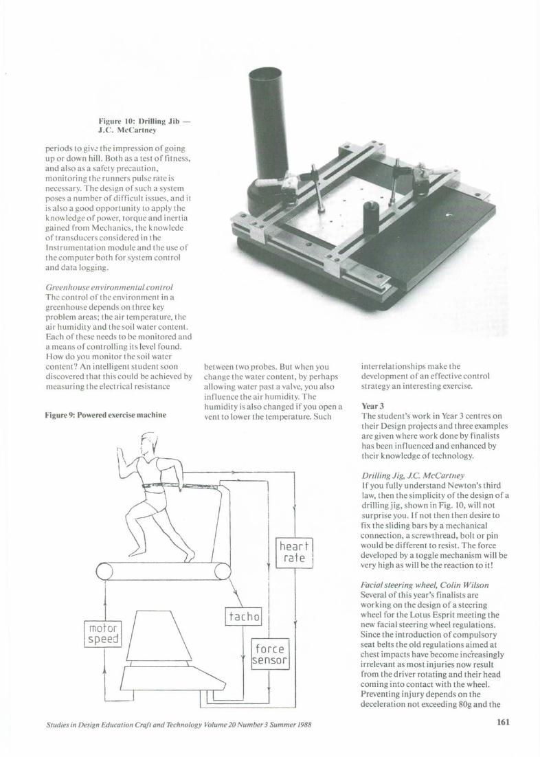
Figure 10: Drilling Jib -J.e. McCartney
periods to giv~ the impression of goingup or down hill. Both as a test of fitness,and also as a safety precaution,monitoring the runners pulse rate isnecessary. The design of such a systemposes a number of difficult issues, and itis also a good opportunity to apply theknowledge of power, torque and inertiagained from Mechanics, the knowledeof transducers considered in theInstrumentation module and the use ofthe computer both for system controland data logging.
Greenhouse environmental controlThe control of the environment in agreenhouse depends on three keyproblem areas; the air temperature, theair humidity and the soil water content.Each of these needs to be monitored anda means of controlling its level found.How do you monitor the soil watercontent? An intelligent student soondiscovered that this could be achieved bymeasuring the electrical resistance
between two probes. But when youchange the water content, by perhapsallowing water past a valve, you alsoinfluence the air humidity. Thehumidity is also changed if you open avent to lower the temperature. Such
interrelationships make thedevelopment of an effective controlstrategy an interesting exercise.
Year 3The student's work in Year 3 centres ontheir Design projects and three examplesare given where work done by finalistshas been influenced and enhanced bytheir knowledge of technology.
Driffing Jig, J.e. McCartneyIf you fully understand Newton's thirdlaw, then the simplicity of the design of adrilling jig, shown in Fig. ~O,will notsurprise you. If not then then desire tofix the sliding bars by a mechanicalconnection, a screwthread, bolt or pinwould be different to resist. The forcedeveloped by a toggle mechanism will bevery high as will be the reaction to it!
heartrat~
forcesensor
Facial steering wheel, Colin WilsonSeveral of this year's finalists areworking on the design of a steeringwheel for the Lotus Esprit meeting thenew facial steering wheel regulations.Since the introduction of compulsoryseat belts the old regulations aimed atchest impacts have become increasinglyirrelevant as most injuries now resultfrom the driver rotating and their headcoming into contact with the wheel.Preventing injury depends on thedeceleration not exceeding 80g and the
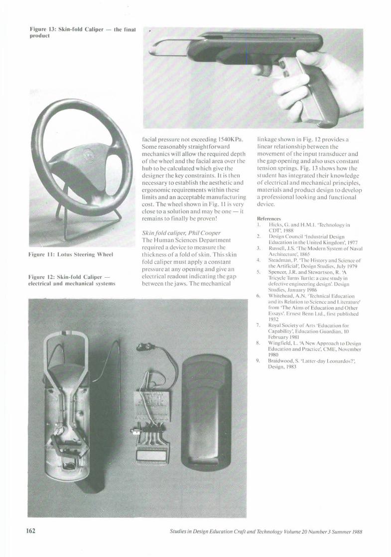
Figure 13: Skin-fold Caliper - the finalproduct
Figure 12: Skin-fold Caliper -electrical and mechanical systems
facial pressure not exceeding 1540KPa.Some reasonably straightforwardmechanics will allow the required depthof the wheel and the facial area over thehub to be calculated which give thedesigner the key constraints. It is thennecessary to establish the aesthetic andergonomic requirements within theselimits and an acceptable manufacturingcost. The wheel shown in Fig. II is veryclose to a solution and may be one - itremains to finally be proven!
Skinfold caliper, Phil CooperThe Human Sciences Departmentrequired a device to measure thethickness of a fold of skin. This skinfold caliper must apply a constantpressure at any opening and give anelectrical readout indicating the gapbetween the jaws. The mechanical
linkage shown in Fig. 12 provides alinear relationship between themovement of the input transducer andthe gap opening and also uses constanttension springs. Fig. 13 shows how thestudent has integrated their knowledgeof electrical and mechanical principles,materials and product design to developa professional looking and functionaldevice.
References!. Hicks, G. and H.M.!. 'Technology in
COT', 19882. Design Council 'Industrial Design
Education in the United Kingdom', 19773. Russell, J.S. 'The Modern System of Naval
Architecture', 18654. Steadman, P. 'The History and Science of
the Artificial', Design Studies, July 19795. Spencer, J.R. and Stewartson, R. 'A
Tricycle Turns Turtle: a case study indefective engineering design'. DesignSt udies, January 1986
6. Whitehead, A.N. 'Technical Educationand its Relation to Science and Literature'from 'The Aims of Education and OtherEssays'. Ernest Benn Ltd., first published1932
7. Royal Society of Arts 'Education forCapability', Education Guardian, 10February 1981
8. Wingfield, L. 'A New Approach to DesignEducation and Practice', CME, November1980
9. Braidwood, S. 'Latter-day Leonardos?',Design, 1983