technological development and needs at eso
TRANSCRIPT
ESO – DoE
Technological Development
and Needs at ESO Industry Day, Brussels, 18-June-2015
Gerald Hechenblaikner
ESO
1
ESO – DoE
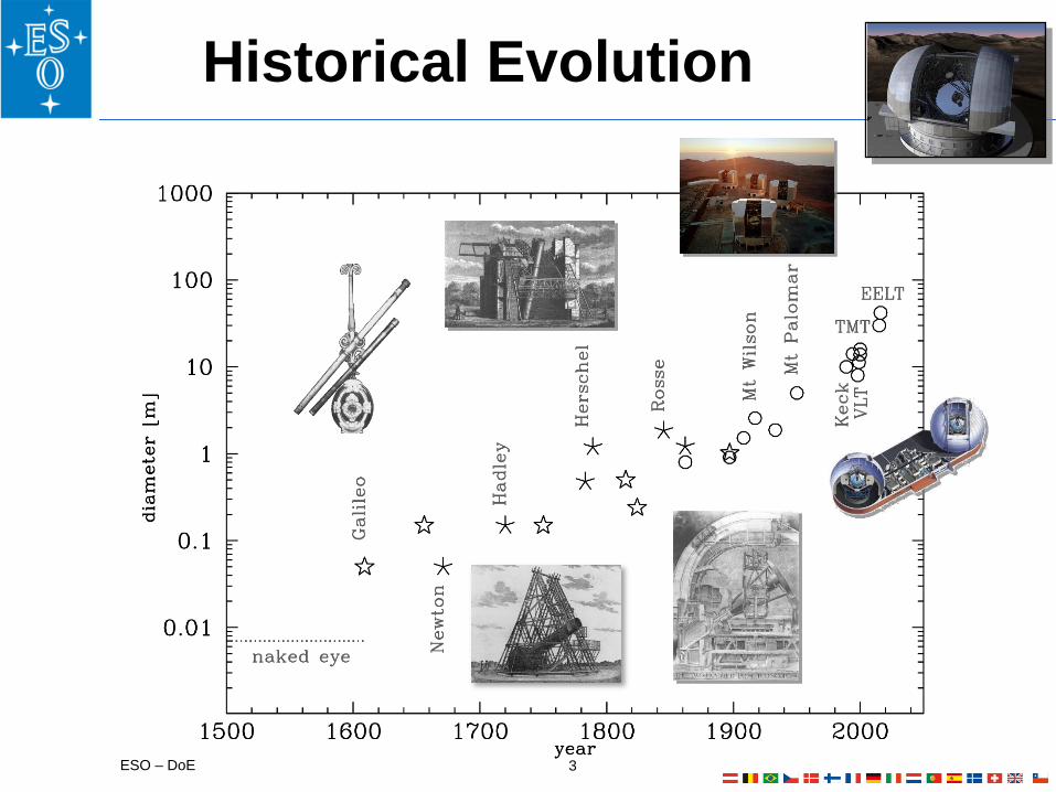
From a small, manually pointed device for visual
observations (around 400 years ago)
large, sophisticated, computer-controlled instrument
with fully digital output
Two properties have been particularly important: the light-collecting power, or diameter of the telescope's mirror (allowing
for the detection of fainter objects), and
the image sharpness, or angular resolution (allowing more detail to be
seen)
The European Southern Observatory (ESO), as a
worldwide leader in astronomy, has developed, together
with industry, several advanced technologies that have
enabled the construction of ever bigger telescopes with
similarly complex instrumentation
Technology in Astronomy
2
ESO – DoE
Historical Evolution
3
ESO – DoE
ESO has contributed to the progress of several
technologies applied to the modern astronomy to improve
the image sharpness, among these: ACTIVE OPTICS
• Preserves optimal image quality by adjusting a “flexible” mirror’s shape with
actuators during observations (i.e. corrects telescope flexure)
• In use in most modern medium and large telescopes
ADAPTIVE OPTICS
• Technology to reduce distortions introduced by atmospheric turbulence
• One of the principal reasons for launching the Hubble Space Telescope was to
avoid this image smearing
INTERFEROMETRY
• The combination of the light collected by two or more telescopes boosts the
angular resolution beyond that of a single telescope
• ESO has been a pioneer in this field with the Very Large Telescope
Interferometer (VLTI) at Paranal
Key-Technology in Astronomy
4

ESO – DoE
Principle of Active Optics
Closed control loop with:
1.Measurement of wave front error
generated by the telescope itself
• Integration times of 30 sec
• Modal analysis using optical
aberrations and elastic modes of
the flexible meniscus mirrors
2.Correction of the errors by the
optical elements of the telescope
• Rigid-body movements of the
mirrors
• Deformation of the mirrors by
adjusting the support forces
5
ESO – DoE
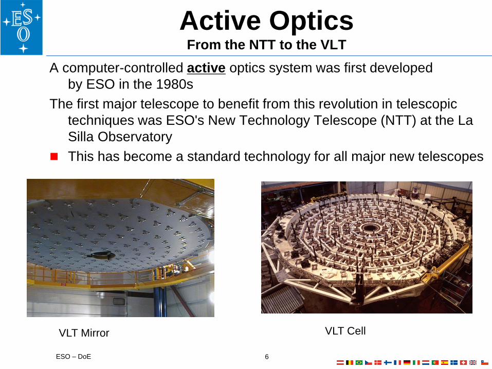
Active Optics From the NTT to the VLT
A computer-controlled active optics system was first developed
by ESO in the 1980s
The first major telescope to benefit from this revolution in telescopic
techniques was ESO's New Technology Telescope (NTT) at the La
Silla Observatory
This has become a standard technology for all major new telescopes
6
VLT Cell VLT Mirror

ESO – DoE
Adaptive Optics
An adaptive optics system (AO) corrects turbulence in the
atmosphere (loop frequency in kHz range), which is
much faster than corrigible by the active optics
7
Active optics:
Shape of the primary mirror adjusted by
stiff actuators to compensate slowly
changing disturbances (gravity flexures,
thermal deformations) on a timescale of
tens of seconds
Adaptive optics:
Shape of a smaller and thinner
deformable mirror adjusted (typically
second Cassegrain mirror “M2” or a
subsequent mirror conjugate to pupil
plane)
Turbulence in the earth atmosphere:
Warm (red) and cool (blue) air cells
(~10 cm) distort the incoming
wavefront from the star.
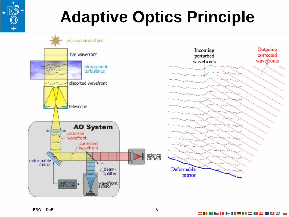
ESO – DoE
Adaptive Optics Principle
8

ESO – DoE
An AO Milestone: MAD
MCAO: 3 Guide stars at 2’, K-band, FWHM:
100-120mas, Sr: >20%, 0.7” seeing,
Exposure 360 s
9
Multi-conjugate adaptive optics demonstrator
(MAD) installed on Nasmyth A of UT3

ESO – DoE
LASER GUIDE STARS
Laser guide stars are artificial stars
generated by excited atomic sodium in
the mesosphere at an altitude of 90km
This requires a powerful laser beam
launched from the telescope. The
yellow wavelength (589nm) is the
colour of a sodium street lamp
Laser for Adaptive Optics
10
LASER DEVELOPMENT
In 2009 ESO demonstrated continuous
output power >50 W at 589nm in a
narrow spectral line
Optical fibre Raman amplifier
technology developed at ESO and
licensed to industry
Milestone industrial demonstrator of
20W using technology developed by
ESO

ESO – DoE
Laser Guide Star Development
11
4LGSF LGSU1 Installation Tests
4LGSF Laser Launch Telescope
Field Selector Beam Steering Mirror
4LGSF Laser Guide Star Unit

ESO – DoE
Adaptive Optics Facility
12
Technical Data of 4LGSF:
4 LGS, off axis up to 330”
2.5-5 Mphot/sec/m2
LGS FWHM <1.2“ on WFS
4 LGSs fixed on pupil
Adaptive Optics Facility (AOF):
2nd generation AO System on UT4
Uses 4LGSF, deformable M2, and
2 WFS modules:
GALACSI for MUSE
GRAAL for Hawk-I
Commissioning in 2015/16
The 4 LGSF in final constellation Laser Room below Hawk I The 1.1 m DSM used for AOF
ESO – DoE
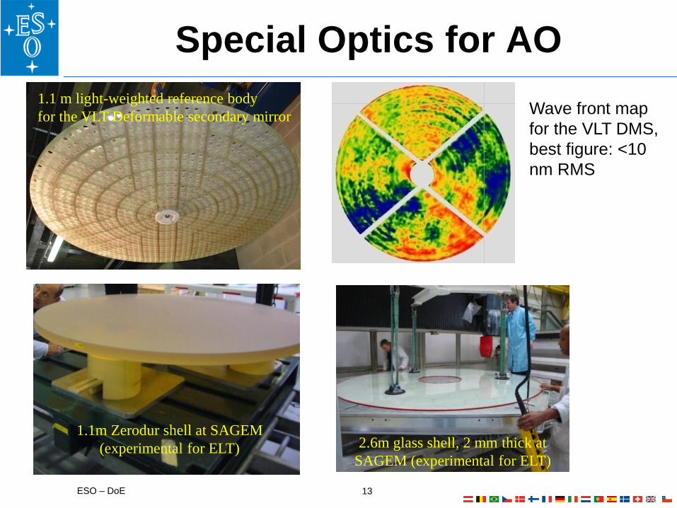
Special Optics for AO
1.1 m light-weighted reference body
for the VLT Deformable secondary mirror
13
2.6m glass shell, 2 mm thick at
SAGEM (experimental for ELT)
1.1m Zerodur shell at SAGEM
(experimental for ELT)
Wave front map
for the VLT DMS,
best figure: <10
nm RMS
ESO – DoE
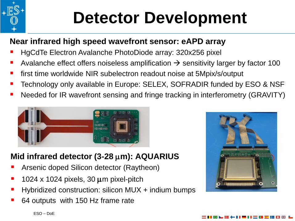
Near infrared high speed wavefront sensor: eAPD array
HgCdTe Electron Avalanche PhotoDiode array: 320x256 pixel
Avalanche effect offers noiseless amplification sensitivity larger by factor 100
first time worldwide NIR subelectron readout noise at 5Mpix/s/output
Technology only available in Europe: SELEX, SOFRADIR funded by ESO & NSF
Needed for IR wavefront sensing and fringe tracking in interferometry (GRAVITY)
Detector Development
Mid infrared detector (3-28 mm): AQUARIUS
Arsenic doped Silicon detector (Raytheon)
1024 x 1024 pixels, 30 mm pixel-pitch
Hybridized construction: silicon MUX + indium bumps
64 outputs with 150 Hz frame rate

ESO – DoE
NGC: Generic Control Electronics
• Controller platform NGC is the result of
three decades of development at ESO
• NGC is a state-of-the art controller for all
detectors at the observatory
• high speed (10MHz) low noise
(sub-electron) AO wavefront sensors
• large format mosaic (VISTA: 256 channels)

ESO – DoE 16
2000 2005 2010 2015 2020 202510
6
107
108
109
1010
1011
1012
1013
NAOS
MACAO
SPHERE
AOFSCAO
NGSGLAO LGSGLAO
ATLAS
MAORY
EAGLE
EPICS
year
Com
ple
xity (
logscale
in M
AC
/s)
Complexity vs time
NAOS
MACAO
SPHERE
AOF
SCAO
NGSGLAO
LGSGLAO
ATLAS
MAORY
EAGLE
EPICS
Figure 1: E-ELT systems complexity in comparison with VLT
systems. Lines are prediction based on Moore’s law, curved line
includes economical limitations.
Table 2: VLT second generation AO instruments, SPARTA delivered computing power
AO
Class
AO
Module
WF
S
Size DM size Frq Complexity
SPHERE XAO Internal 1 40x40 1 1377 1500 5.2 GMAC
AOF LTAO Internal 4 40x40x4 1 1170 1000 11.8 GMAC
Figure 1 shows the complexity as a function of
time assuming arbitrary first light dates for the
various instruments starting from the foreseen
telescope first-light in 2018. Order of
instruments is arbitrary. Systems currently in
operation in Paranal are also shown, placed on
their respective commissioning date. One can
recognize 3 clusters, one with GLAO+SCAO
modes, MAORY/ATLAS/EAGLE and
separately EPICS. Bars account for a range of
different requirements.
The two lines centered in the AOF coordinate
describe the expected technological evolution in
terms of the so-called Moore’s Law.
2. THE MOORE’S LAW
Considerations about future trends in computing
cannot avoid citing the Moore’s law5.
The Moore’s law describes a long-term trend in
the history of computing hardware, in which the
number of transistors that can be placed on an
integrated circuit has doubled approximately
every two years. The actual period was about 20
months. The purple line uses the ’20 months’ rule, while the yellow line uses ’24 months’. In both cases the complexity
of almost all instruments lies below or around the expected trend in technological evolution, with the notable exclusion
of EPICS. It is also to be noted that centering the lines around AOF is rather arbitrary since this is not the limit of the
current technology in its incarnation (SPARTA), but instead is what it delivers in one of its instances. Limits are actually
higher, but even increasing the height of the two Moore’s law line would not reach the requirements posed by EPICS.
Is the Moore’s law to be believed for the future?
The literature abounds in papers treating this subject in details. First of all it has to be noted that the Moore’s law
consider the growth in the number of components that can be squeezed in the same area and that does not always
translate into greater practical CPU performance. Therefore the technological evolution predicted in Figure 1 does not
immediately refer to more powerful architectures, but simply to denser CPUs. There are cases where a roughly 45%
increase in processor transistors have translated to roughly 10–20% increase in processing power (see [2]).
There are more factors limiting the computer power that can be obtained from a densely populated piece of silicon, such
as internal bandwidth and storage speed. In fact CPU speed has improved as has the memory size. However memory
access speed has failed to keep up resulting in the real bottleneck for high performance systems.
For years, processor makers consistently delivered increases in clock rates and instruction-level parallelism, so that
single-threaded code executed faster on newer processors with no modification. Now, to manage CPU power dissipation,
processor makers favor multi-core chip designs, and software has to be written in a multi-threaded or multi-process
manner to take full advantage of the hardware, with the CPU speed stabilized at around 3GHz.
There are several papers on the subject, mostly focusing on the insurmountable technological barriers that will be
reached, like the size of an atom. Certainly it looks like the speed limit has been reached, since in the last years
processors stabilized their clocks at 3 GHz.
5 Part of the text in the following paragraphs/sections extracted or adapted from Wikipedia.
Real Time Computer & Control
SPARTA dev @
ESO today
RTC box
Co-processing cluster
GB Ethernet Switch
Future E-ELT
needs
RTC for MACAO
in 2002

ESO – DoE
VLT – Main-Axes Drive System
VLT is well known for its excellent tracking
performance. The four main contributors to
this technology are:
1.Direct drive motors
2.Collocated encoders
3.Hydrostatic bearing system
4. Innovative control algorithms
17
ESO – DoE
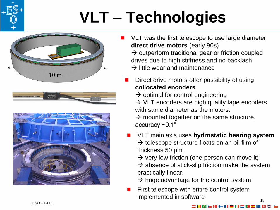
VLT – Technologies VLT was the first telescope to use large diameter
direct drive motors (early 90s)
outperform traditional gear or friction coupled
drives due to high stiffness and no backlash
little wear and maintenance 10 m
18
VLT main axis uses hydrostatic bearing system
telescope structure floats on an oil film of
thickness 50 µm.
very low friction (one person can move it)
absence of stick-slip friction make the system
practically linear.
huge advantage for the control system
Direct drive motors offer possibility of using
collocated encoders
optimal for control engineering
VLT encoders are high quality tape encoders
with same diameter as the motors.
mounted together on the same structure,
accuracy ~0.1”
First telescope with entire control system
implemented in software

ESO – DoE
VLTI = VLT & Interferometry
19
ESO – DoE
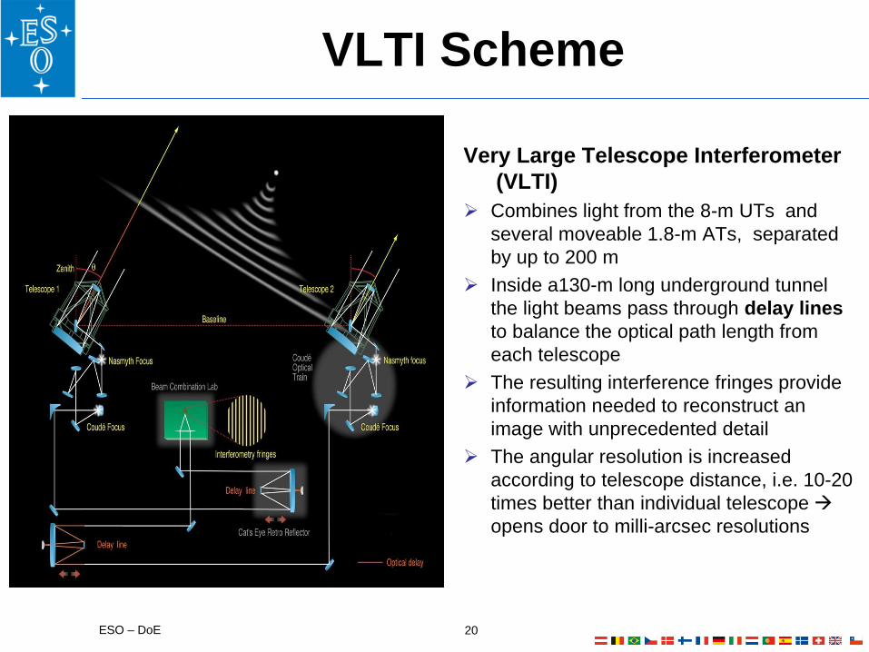
VLTI Scheme
20
Very Large Telescope Interferometer
(VLTI)
Combines light from the 8-m UTs and
several moveable 1.8-m ATs, separated
by up to 200 m
Inside a130-m long underground tunnel
the light beams pass through delay lines
to balance the optical path length from
each telescope
The resulting interference fringes provide
information needed to reconstruct an
image with unprecedented detail
The angular resolution is increased
according to telescope distance, i.e. 10-20
times better than individual telescope
opens door to milli-arcsec resolutions

ESO – DoE
The ALMA Partnership
ALMA=Atacama Large Millimeter / sub-millimeter Array:
Giant array of 50 12-m radio antennas, which can be configured to achieve
baselines up to 16 km for highest angular resolution
Additional, compact array of 7-m and 12-m antennas for large field-of-view
ALMA is equipped with state-of-the-art receivers that cover all the
atmospheric windows up to 1 THz
21
Some challenges:
Continuous day and night operation at
the Array Operations Site (AOS) at
5000m in the Atacama desert
Strong wind conditions of 6-9 m/s
Temperature extremes of -20C to
+20C and large temporal gradients
Seismically active region

ESO – DoE
ALMA Antennas
22
ALMA is a global partnership in astronomy:
Europe (ESO): 25 x 12-m antennas
Industrial Contractors: AEM – Thales-Alenia Space, European Industrial
Engineering and MT Mechatronics
North America (US, Canada, Taiwan): 25 x 12-m antennas
Industrial Contractors: Vertex, part of General Dynamics Corporation
East Asia (Japan, Taiwan): 4 x12-m 12 x 7-m antennas
Industrial Contractors: MELCO, part of Mitsubishi Electric Corporation

ESO – DoE
Instrument Technologies
23
ExampleMUSE is the Multi-Unit Spectroscopic Explorer at UT4
• composed of 24 identical cameras providing a 1 arcmin2 image optical
spectrum for each pixel
• 24 CCD cameras and dewars built by ESO
• Instrument built over 10 years by Center of Astrophysical Research in Lyon
(CRAL).

ESO – DoE
VLT MUSE cooling system with 24 identical CCD
cryostats
Single detector head cryostat for MUSE
Wave front sensor cryostat for GRAVITY
Cryogenic Systems & Lines Cooling systems and cryostats down to 3 Kelvin, small and large scale
Manufacturing and testing qualification of transfer and
distribution lines for liquid nitrogen

• Manufacturing of small accurate parts
• Materials: Aluminum, martensitic and
austenitic stainless steels, copper…
Manufacturing small and large structures
• Final machining of large structures
including in some case in-situ
metrology for accurate references
Custom gears and worm gear systems
• Manufacturing of stainless
steel structures

• Aluminum structures: Manufacturing Techniques
• Forming of aluminum
• TIG welding
• Thermal treatments
• Machining.
Manufacturing Cryostats and vacuum chambers
• Manufacturing & testing
• vacuum chambers
• LN2 cryostats (including intermediate
thermal shocks)
• Aluminum structures:
Cryogenic applications
• intermediate treatment
• temperature ageing
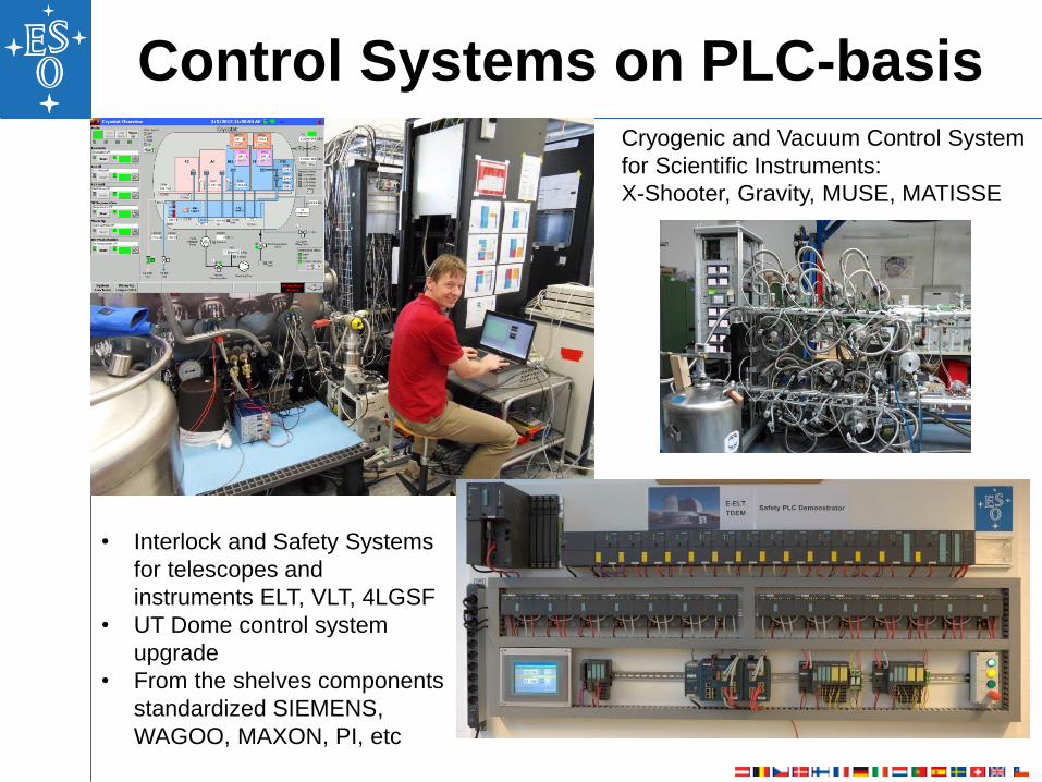
Control Systems on PLC-basis Cryogenic and Vacuum Control System
for Scientific Instruments:
X-Shooter, Gravity, MUSE, MATISSE
• Interlock and Safety Systems
for telescopes and
instruments ELT, VLT, 4LGSF
• UT Dome control system
upgrade
• From the shelves components
standardized SIEMENS,
WAGOO, MAXON, PI, etc

ESO – DoE
Obsolescence management
• HW Virtualization: keep HW and SW interfaces untouched
o Today Design and back engineering made by ESO
o Shall be outsourced FPGA and schematic design, Layouting,
production, tests
28
ESO – DoE
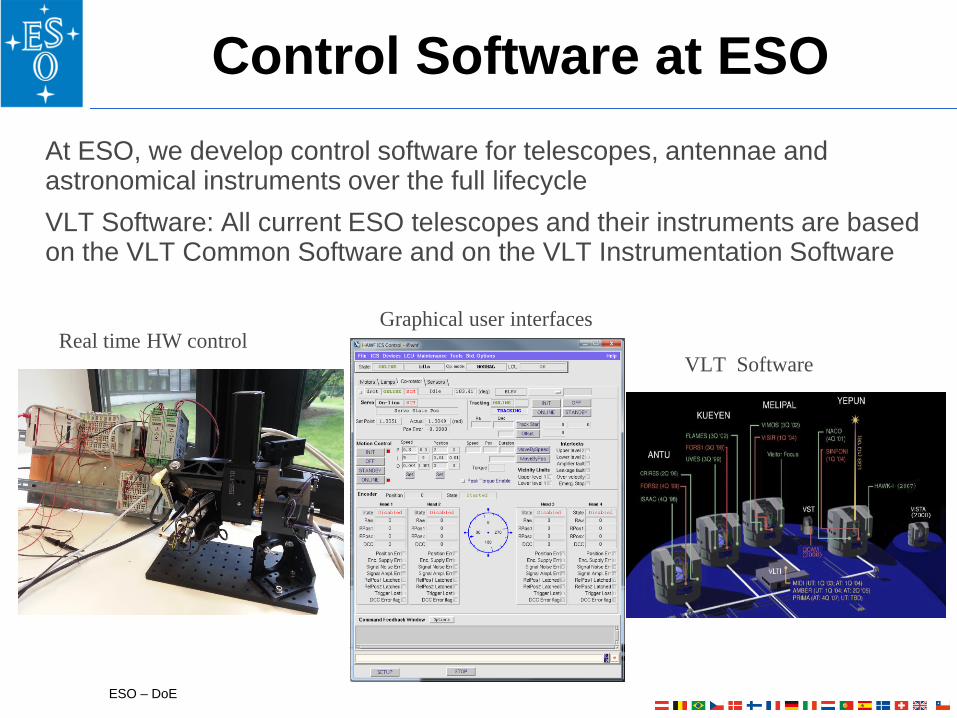
Control Software at ESO
At ESO, we develop control software for telescopes, antennae and astronomical instruments over the full lifecycle
VLT Software: All current ESO telescopes and their instruments are based on the VLT Common Software and on the VLT Instrumentation Software
Real time HW control Graphical user interfaces
VLT Software
ESO – DoE Astronomy with Megastructures, Crete, 10 May 2010
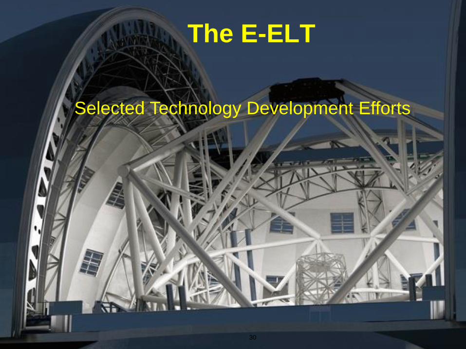
The E-ELT
30
Selected Technology Development Efforts

ESO – DoE
FEA and CFD Analyses
M1 Segment subunit detailed FE
model
M1 Edge Sensor stresses
E-ELT Dome wind velocity distribution
Wind Tunnel Tests for Dome and Main Structure
•Validation of in-house CFD analyses
•Input to specification requirements
ESO – DoE
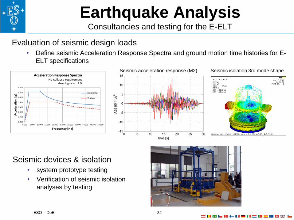
Earthquake Analysis Consultancies and testing for the E-ELT
Evaluation of seismic design loads
• Define seismic Acceleration Response Spectra and ground motion time histories for E-
ELT specifications
32
Seismic devices & isolation
• system prototype testing
• Verification of seismic isolation
analyses by testing
Seismic acceleration response (M2) Seismic isolation 3rd mode shape

ESO – DoE
E-ELT mirror handling handling & treating large mirrors
33
1. E-ELT segment handling system for M1
2. E-ELT large mirror handling system for M2, M3:
gantry with 5 DoF, precision movement, force
control
3. Mirror cleaning and washing facilities
4. Coating tank with infrastructure for applying y
multi-layer coatings on glass-ceramic substrates (ca
4m diameter)
1. 2. 3.
4.

VLT - Model-based controller design
based on frequency models
Control System Design
ALMA - Model-based non-linear
damping system design
EELT - Prototyping and design of M1
and M5 control systems
Presentation of EELT technical
concepts to the public
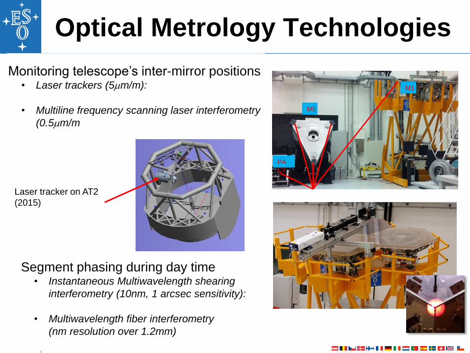
Optical Metrology Technologies
Monitoring telescope’s inter-mirror positions • Laser trackers (5mm/m):
• Multiline frequency scanning laser interferometry
(0.5mm/m
PA
CT
M5
M1
Segment phasing during day time • Instantaneous Multiwavelength shearing
interferometry (10nm, 1 arcsec sensitivity):
• Multiwavelength fiber interferometry
(nm resolution over 1.2mm)
Laser tracker on AT2
(2015)

ESO – DoE
Detector Mosaics
OmegaCAM CCD mosaic
268 M Pixel, 32 CCDs,
NEW: 9Kx9K e2v CCDs for ESPRESSO
Also to be used in ELT instruments
HAWK-I near infrared mosaic
4 x 2Kx2K HgCdeTe Hawaii2RG arrays
Cutoff wavelength λc = 2.5 μm
128 parallel video outputs
cryogenic preamplifiers MICADO (ELT Instrument): mosaic of 16x4Kx4K Hawaii-4RG-15 arrays
Near infrared
Optical

ESO – DoE
General Technology Needs
Optics
Detectors
Mechanical structures
Cooling and chiller system
HVAC
Cranes and handling equipments
Mirror coating facilities
Actuators
Controllers
SW
Power generation systems
Power distribution
Waste and chemicals treatment
Pulsed laser at specific frequency/wavelength
Consultancy (RAMS, PA, QA)
Only a few examples are given above…..
37
ESO – DoE
Technology needs in Astronomy
Optics
Detectors
Mechanical structures
Cooling and chiller system
HVAC
Cranes and handling equipments
Mirror coating facilities
Actuators
Controllers
SW
Power generation systems
Power distribution
Waste and chemicals treatment
Pulsed laser at specific frequency/wavelength
Consultancy (RAMS, PA, QA)
…….
Thank you!
38