technological development of internal heat-integrated
TRANSCRIPT
Research paper
−158−Synthesiology - English edition Vol.7 No.3 pp.158-173 (Dec. 2014)
of C5-splitter existing in the Chiba factory of Maruzen Petrochemical was selected as the subject of the project objective. A continuous 1000 hour test run was successfully achieved with higher than 60 % of energy saving rate.[1]-[3]
As the existing C5-splitter was treating a clean service producing pure cyclopentane from a mixed gasoline, a packed-column type HIDiC pilot plant was manufactured by Kimura Chemical Plants. The reasons why a packed column structure was selected were because(1) substantial data were available of the basic research
of HIDiC process and system accumulated by Kyoto University and AIST,
(2) large energy-saving rate can be expected if internal reflux liquid is distributed evenly over the heat transfer surfaces of packed columns,
(3) no problem of fouling and plugging/blockade owing to the clean service of petrochemicals.
Thereafter a collaborative study of HIDiC consortium was conducted by AIST serving as the leader for the purpose of practical propagation of HIDiC technology. However although the very high energy-saving effect of HIDiC technology was recognized, no commercial-scale HIDiC system was realized. One of the reasons was that most of petrochemical companies had more than enough volume of steam from the direct cracking process which releases high temperature cascade heat. A more important problem was that a big compressor with a large discharge rate was required in the HIDiC system. In addition, an original HIDiC system was not suitable for dirty service of distillation. For example,
1 Introduction
Distillation process serving as the leading part of separation technologies occupies approximately 40 % of the total energy consumed by chemical industry in Japan. Many years have passed since the national program of energy conservation started. Our fundamental research on the energy saving distillation technology by internal heat integration (called “The first-term project”) was conducted as a project of the New Sunshine Program. After the first-term project, our next-phase project entitled “Development of energy-saving distillation technology by internal heat integration” (called “The second-term project”)[1][2] was conducted for four years from 2002 as part of the new technology NEDO program for prevention against global warming, NEDO being the New-Energy and Industr ial Technology Development Organization. The objective of the second-term project was to contribute to the development of energy-saving technology for reducing the consumption of fossil resources. The project team[1] consisted of the National Institute of Advanced Industrial Science and Technology (AIST) serving as the project leader, Maruzen Petrochemical Co., Ltd., Kimura Chemical Plants Co., Ltd., Kansai Chemical Engineering Co., Ltd., Taiyo Nippon Sanso Corporation, and Kobe Steel, Ltd. The target of our project authorized by NEDO was specified to be 30 % or more reduction of the energy consumed by an ordinary distillation column.
The petrochemical industry group in this team successfully constructed a pilot plant of HIDiC packed column in February, 2005. The first column (bubble-cap trayed column)
- Substantive research of application to a bench plant of bioethanol distillation-
To dramatically reduce energy consumption in chemical industry, we propose to construct a database on fundamental technologies for practical applications of HIDiC, as part of a project funded by NEDO (New Energy and Industrial Technology Development Organization). An application of HIDiC to the distillation process for the enrichment of bioethanol fermented from biomass has been attempted, and a bench plant has been designed and constructed to ensure practical applicability. Testing has shown that the developed HIDiC system achieves the project targets of enrichment and energy savings. We also confirmed that a compressor-free HIDiC system can be scaled to commercial plants.
Technological development of internal heat-integrated distillation column (HIDiC)
Keywords : HIDiC distillation column, bioethanol distillation, internal heat integration, energy saving, lift tray, bench plant
[Translation from Synthesiology, Vol.7, No.3, p.163-178 (2014)]
Kunio KataoKa* and Hideo Noda
Kansai Chemical Engineering Co. Ltd., 2-9-7 Minami-nanamatsu-cho, Amagaki 660-0053, Japan *E-mail:
Original manuscript received February 25, 2010, Revisions received December 24, 2010, Accepted December 24, 2010
Research paper : Technological development of internal heat-integrated distillation column (HIDiC) (K. KATAOKA et al.)
−159−
Synthesiology - English edition Vol.7 No.3 (2014)
it was difficult to treat biomass product mixtures such as bioethanol and biodiesel solutions including lignins, glucans, ashes, and enzyme proteins as fermentation residues. Consequently Kansai Chemical Engineering devised a new HIDiC system which does not need a compressor (called “compressor-free HIDiC” and CF-HIDiC for short). In order to develop this patented system,[4] our own project (called “The third-term project”)[5] was conducted by ourselves for three years from 2007. As a result, it was confirmed that the compressor-free HIDiC system could give more than 30 % reduction of energy consumption.
On the other hand, another NEDO project for the development of biomass energy such as biofuel ethanol came up focusing on the energy saving of enriching processes as well as cost reduction of enzyme and yeast. We joined that NEDO project to boost bioethanol distillation. The project was entitled “Development of environment-friendly overall processes for high-efficiency production of bioethanol” (2008 ~ 2012).[6] In this project (called “The fourth-term project”), we were assigned to apply our new HIDiC technology to the dirty-service distillation for enriching bioethanol from the fermented mash. We succeeded at long last in constructing a HIDiC bench plant in 2012. It was confirmed by our test operation that the project target of energy consumption allocated to the enriching process was successfully achieved, and thus the possibility of practical application of our developed HIDiC system was shown. In the following part of this paper, we would like to discuss from various viewpoints of Synthesiology how this HIDiC technology was developed as well as how our sequential projects were conducted.[7]
2 How to execute a project for technological development
Details of development of the technology are explained in chapters 3 and 4. From the viewpoint of Synthesiology, in this chapter, the following issues will be analyzed and discussed to extract a methodology of technological development from our experience: (1) how to execute various phases of projects for the technological development, and (2) how to attain a breakthrough to overcome various difficult problems.
2.1 How to grasp technological issues and how to make project purposes definiteThe main subject of the NEDO second project (No. P02020: Technological development of internal heat-integrated distillation column for energy conservation) was derived from the Kyoto Protocol for the prevention of global warming. That was a very important national policy of energy and environment recognizing that a big effect of energy saving in distillation processes of chemical industry would lead to the reduction of the import volume of crude oil and the reduction of greenhouse gas emissions. Regarding the energy-saving technologies in chemical industry of the day, after the oil crises, various process improvements for
eliminating waste of energy and materials were already performed in the chemical industry. Further reduction of energy consumption was assumed almost impossible unless drastic measures of technological innovation were realized.
Historically speaking, an idea of introducing a heat pump into a distillation system was first proposed by Mah et al.(1977).[8] Unfortunately nobody had thereafter paid earnest attention to it. No distillation engineering researchers could have a concrete image of its practical internal structure because their paper discussed its possibility by system analysis only from a viewpoint of process system engineering. A big fireproof compressor required for pressurizing the rectifying section was regarded inadequate for distillation processes. Then the late Prof. Takamatsu of Kyoto University recognized that a national project of technological development for introducing the principle of heat pump into distillation would be noteworthy for the drastic reduction of energy consumption in chemical industry.
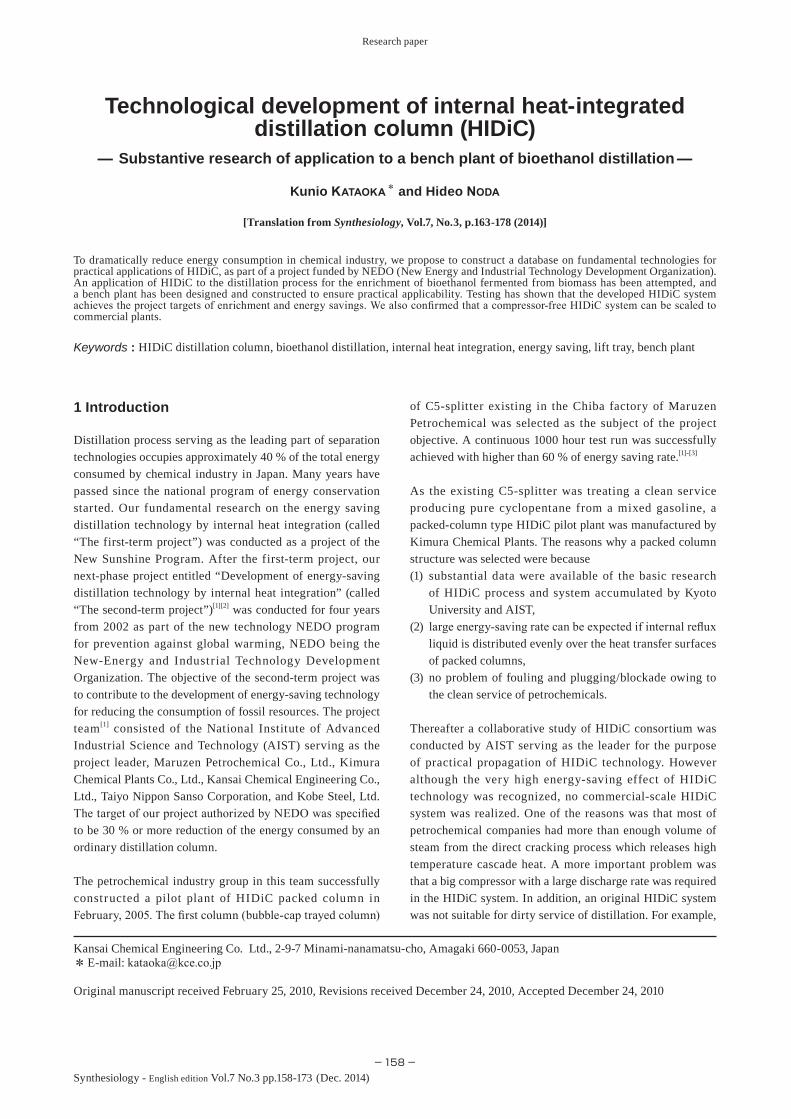
The standard system of internal heat-integrated distillation column (called HIDiC for short)[8] proposed at the beginning of the first-term project is shown in a form of double-tube type structure in Fig. 1. The vapor issuing from the top of the stripping section is pressurized by a compressor and supplied into the bottom of the rectifying section. Therefore the temperature of the rectifying section can be made higher than that of the stripping section. If the high-temperature rectifying section comes into thermal contact with the low-temperature stripping section, partial condensation of upward-rising vapor occurs in the rectifying section while partial vaporization of downward-falling liquid occurs in the stripping section owing to the internal heat transfer from the rectifying to the stripping section. The partial vaporization due to this internal heat exchange can greatly reduce the heat duty of the bottom reboiler. The partial condensation in the rectifying section can also reduce the cooling duty of the overhead condenser.
Fig. 1 Standard HIDiC system (Double-tube type)
Auxil. heaterInternal heat exchange
(Inner column → Outer column)
Overhead product
Bottom product
Stripping sec.(Annular space of
outer column)
Rectifying sec.
(Inner column)
Flash drum
Compressor or vacuum pump
Condenser
Reboiler
Feed
Research paper : Technological development of internal heat-integrated distillation column (HIDiC) (K. KATAOKA et al.)
−160−Synthesiology - English edition Vol.7 No.3 (2014)
2.2 Cooperation of heat transfer engineering with process system engineeringThe first-term project was started by process system engineers and researchers who noticed the significance of the idea of Dr. Mah et al.[8] Their project team was organized in concert with a petrochemical company and plant engineering companies. The education and research on distillation of the day were done based on the thermodynamics of vapor-liquid equilibrium and the process system engineering using an ideal plate model.
However we know that the distillation process essentially proceeds due to simultaneous heat and mass transfer. One of the authors thereafter joined the second-term project as a researcher of heat transfer engineering. We discussed and amended together the objective of the second-term project in order to construct a database of internal heat integration character istics based on the concept of heat t ransfer engineering. The internal heat transfer due to the temperature difference between the rectifying and stripping sections can be analyzed with an overall heat transfer coefficient U and an effective heat transfer area A.
An important issue was to observe a control parameter set of U and A as the characteristics of internal heat transfer by an experimental apparatus of practical-scale HIDiC column. A database of UA made it possible to perform a process simulation analysis of the commercial-scale HIDiC plant design for various distillation processes. As mentioned above, the second-term project succeeded in the construction of a packed column-type HIDiC pilot plant as an alternative of the first column of the existing C5-splitter taking into account the process simulation analysis.[2][3]
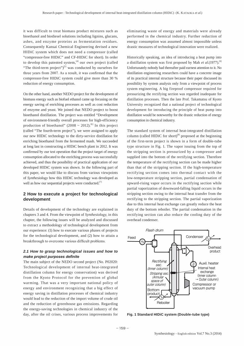
2.3 Devising a new HIDiC system for propagation – The third-term project –By using mixed gasoline including cyclopentane as a key component, the second-term project succeeded in a continuous 1000 hour test run of the pilot plant with a very high rate (more than 60 %) of energy saving, which was constructed as an alternative of the C5-splitter first column. However commercial-scale application following this pilot plant was not realized. This was due to the fact that the success was achieved by the standard HIDiC system equipped with a large compressor for a clean service distillation of petrochemical hydrocarbons. Usually there are various dirty mixtures and inflammable mixtures to be separated by distillation. After considering various issues, we devised a compressor-free HIDiC (called “CF-HIDiC” for short). Figure 2 shows a compressor-free HIDiC flow system.[4][5]
The third-term project proposed by Kansai Chemical Engineering was approved by NEDO expecting a useful outcome of this new HIDiC system. The CF-HIDiC system consists of two columns at least, where the first one is an ordinary column and the second one is a double-tube HIDiC
column. The first column can supply its high-pressure overhead vapor into the bottom of the HIDiC rectifying section without a compressor. The creative part is that the first column does not have an overhead condenser but the stripping section of the HIDiC column has an overhead condenser, and of which the condensate is fed back to the top of the first column. Although there is vaporization of the internal ref lux liquid in the HIDiC stripping section due to the internal heat exchange, we provided an overhead condenser for condensing the overhead vapor of the HIDiC stripping section. That was regarded as a negative idea against the basic concept of HIDiC even in the project meeting. However the overhead condenser of the HIDiC stripping section can be regarded as an alternative of the first column condenser. In addition, its reflux liquid pump has negligible small power consumption in comparison to that of vapor compressors.
It is natural that the energy-saving effect of the CF-HIDiC is lower than that of the standard HIDiC because the first column is an ordinary column with no HIDiC energy-saving effect. However, with the advantage that no compressor is required, the CF-HIDiC has a possibility of more than 30 % reduction of energy consumed by an ordinary two-column system. The third-term project was started as a fundamental study by Kansai Chemical Engineering with the expectation that this CF-HIDiC system could be scaled to a commercial-scale big plant. In spite of the wild idea of the HIDiC stripping section equipped with an usual overhead condenser, the CF-HIDiC system was patented with no objections.[4] Owing to the fact that no compressor was required, this system had good evaluation as a new HIDiC system with expectations for a considerably high energy-saving effect.
Fig. 2 Compressor-free HIDiC system (called CF-HIDiC for short)[4][5]
Internal heat exchang
(Inner column → Outer column)
Overhead product
Bottom product
Bottom product Stripping sec.
(Annular space)
Rectifying sec.(Inner column)
CondenserCondenser
Reboiler
Feed
First column (Ordinary column)
Second column (HIDiC column)

Research paper : Technological development of internal heat-integrated distillation column (HIDiC) (K. KATAOKA et al.)
−161−
Synthesiology - English edition Vol.7 No.3 (2014)
2.4 Search for a road contributive to practical use – The fourth-term project –Taking into account that various enlightening movements for practical propagation of the CF-HIDiC did not gain good results, we amended our aim to boost different applications involved in other projects. We joined a NEDO project (No. P07015) entitled “Development of environmentally benign and consolidated process for efficient production of cellulosic ethanol.” The purpose of the project was technological process development for high-eff icient production of bioethanol from soft biomass. As the authorized target of the project, the total cost of production of 1 litre of dehydrated ethanol was set at JPY 40/L-EtOH (USD 0.4/L-EtOH). The main objectives of the project were (1) how to reduce the cost of the enzyme and yeast consumption, (2) how to make use of the arming technology displaying both cellulase and hemicellulase on the surface of yeast cells for simultaneous saccharification fermentation. However the ordinary distillation technology selected as the first candidate for enriching the fermented mash did not permit a drastic reduction of energy requirement. In order to realize a big reduction in the total cost of production, it was of great importance to innovate HIDiC technology within the total process of producing ethanol highly efficiently from biomass. Taking into account that the process producing ethanol from biomass can be regarded as a carbon-neutral process, we decided to join the project in order to make a contribution to a dramatic reduction of energy consumption required for the bioethanol process.
2.5 Challenge to application for a new process – A troublesome problem should be regarded as a true need for innovation –The fermented mash produced from soft cellulosic biomass contains various fermentation residues, saccharides, lignins, enzymes, and inorganic salts, some of which remain as non-volatile substances in the liquid mixture even after filtration. It was feared that these non-volatile substances might obstruct heat transfer fouling the heat transfer surfaces of the HIDiC column and the reboiler. We faced a very important problem as to how to try fouling tests before making the structure of HIDiC bench plant concrete. We hit upon a good idea making use of our original jacketed tank evaporator (named “Wall Wetter Evaporator”) as a simulated double-tube type HIDiC column. As will be mentioned later in Fig. 9, the inner surface of the evaporator kettle can be regarded as the heat transfer surface of the HIDiC stripping section whereas the outer jacket-side surface serves as the heat transfer surface of the HIDiC rectifying section. The fouling test using mash liquid fermented from rice straw successfully investigated the effect of the boiling point by varying the operating pressure of the evaporator kettle.
2.6 Conflict between goals of energy conservation and fermentation – Reconsideration of respective goals –
The bioprocess team was also facing difficulty in raising the ethanol yield of fermented mash. Large amount of energy would be assigned to the enriching process team for vaporization of a lot of water. Therefore, the ethanol concentration of fermented mash directly inf luences the energy-saving rate in the distillation process by HIDiC.
We, the enriching distillation team discussed with the bioprocess team of saccharification and fermentation on how high they could raise the ethanol yield by the fermentation process. The result of ethanol yield that the bioprocess team had reached at that time by the consolidated bio-processing process (abbreviated “CBP” process) amounted to 2 wt% of ethanol at the highest. For the case of the clean ethanol-water system, we analyzed by process simulation as to what concentration level of fermented mash ethanol was necessary in order for the standard HIDiC to attain the project target of energy savings. The result of the simulation analysis is shown in Fig. 3. Using Fig. 3, we insisted that, in order for the distillation team to attain the energy-saving target (allocated 4 MJ/L-EtOH for the standard HIDiC), the fermentation target of the bioprocess team should be raised up to 5 wt% of ethanol taking into account the fouling effect of the actual mash. The simulation analysis making use of the HIDiC database constructed in the third-term project was helpful for the reconsideration of the project targets.
2.7 Bench plant design specifications and test run results of the actual bench plantAt that time, HIDiC design manual had not been constructed because the internal structure of the HIDiC system was not yet definite. Fortunately we already owned an experimental apparatus of a commercial-scale double-tube trayed HIDiC column (The outer column: 800 mm ID and the inner column: 508 mm ID) and a big database of internal heat integration characteristics. These data were very useful for the process simulation analysis determining the design specification of the bench plant. As it was difficult to experimentally observe
Fig. 3 Variation of energy requirement for standard HIDiC system with mash liquid ethanol concentration[6]
Feed concentration wt%
Energy requirement MJ/L-EtOH
0
1
2
3
4
5
6
7
8
9
2 4 6 8 10 120
Research paper : Technological development of internal heat-integrated distillation column (HIDiC) (K. KATAOKA et al.)
−162−Synthesiology - English edition Vol.7 No.3 (2014)
the actual area of the internal heat exchange, for engineering purposes, the effective heat transfer area was estimated as the cylindrical surface area of the inner column determined from unit tray-to-tray spacing of actual trays. Therefore the overall heat transfer coefficient was underestimated as U = 250 kcal/m2hºC, i.e. 290.75 W/m2K. For bench plant design specification, the feed rate of the fermented mash liquid after filtration was set at 50 kg/h and its concentration was 5 wt% EtOH. The simulation analysis using this condition made the system design very easy. The result of simulation analysis will be given in Fig. 10.
Owing to the height limit (10 m or less) of the building, we were anxious about the deficiency in the number of trays for the first column (mash column) of CF-HIDiC equipped with 16 Change Trays. As will be shown in Fig. 16, the project target for energy requirement (5 MJ/L-EtOH) was actually just attained for the case of CF-HIDiC system.
2.8 Test operation of bench plant – Procedure and result –Regarding how to start up, we experimentally tried various ways and discussed the procedures carefully.As a result, the start-up procedure is given as follows.(A) Standard HIDiC (see Fig. 12)
(1) Exhaust air from the stripping section through the overhead condenser of the rectifying section by a dry vacuum pump, (2) supply live steam into the bottom of the stripping section, (3) then make both the rectifying and stripping sections full of steam only, (4) then start the supply of mash liquid as the feed (5) lower the pressure of the stripping section for the specified compression ratio under the total reflux condition, (6) adjust the column top temperature of the rectifying section near to azeotropic point reducing the live steam supply into the stripping section, and finally reduce the reflux ratio as much as possible in order to reach a steady state for obtaining the specified overhead product. At the optimum energy-saving condition, the live steam supply can be made exactly zero.
(B) CF-HIDiC (see Fig. 14)(1) Supply live steam into the bottom of the first column (mash column) in order to exhaust air or non-condensable gas of the first column and the HIDiC rectifying section from its overhead condenser, (2) then operate the two overhead condensers, (3) lower the HIDiC stripping section pressure by a water-sealed vacuum pump in order to bring the HIDiC column to an internal heat exchange condition, (4) t ranspor t the bot tom liquid (water) condensed in the HIDiC rectifying section to the top of the HIDiC stripping section by the pressure difference, (5) supply live steam into the HIDiC stripping section bottom, (6) feed-back the condensate as a reflux from the HIDiC stripping section overhead condenser to the top of the first column, (7) discharge the internal reflux liquid
(water) from both the bottoms of the HIDiC stripping section and the first column, (8) then supply a mash liquid solution as the feed into the feed plate of the first column, (9) reduce the live steam supply into the HIDiC stripping section as much as possible, and (10) adjust the pressure ratio between the HIDiC rectifying and stripping sections reducing the live steam supply into the first column bottom so as to even out the top temperature of the HIDiC rectifying section down near to the azeotropic point. Comparing the start-up operation between the standard HIDiC and CF-HIDiC, the latter has been found to be much easier.
2.9 Key to achievement of the project target of energy savingAs a result of preliminary investigation, the purpose of the distillation team became how to reduce the live steam supply in place of the reboiler heat duty. As was anticipated, the live steam supply into the HIDiC stripping section could be saved much owing to the great effect of internal heat integration. Actually it became zero not only for the standard HIDiC system but also for the CF-HIDiC system. Regarding the standard HIDiC, we assured that the whole distillation system could be operated by electric power consumption only required for the dry vacuum pump. On the other hand, the energy-saving effect of the CF-HIDiC depended on how to reduce the live steam supply into the first column bottom in place of the bottom reboiler heat duty. The water-sealed vacuum pump installed beneath the overhead condenser of the HIDiC stripping section usually requires a negligibly small (of the order 1/100) electric energy consumption. In addition, the live steam supply into the HIDiC stripping section could be made zero at the optimum condition. However when the live steam supply into the first column bottom was largely saved, the ethanol concentration of the bottom product of the mash column rose beyond the effluent control (< 0.1 wt%). Regarding the CF-HIDiC, when the live steam supply was made 10.55 kg/h, we achieved at the lowest the energy-saving target (5 MJ/L-EtOH) satisfying the enriching target (more than 90 wt% EtOH) of the overhead product as well as the effluent control. It was also confirmed that the problem could be relieved if sufficient number of trays of the first column is permitted without the height limitation.
3 Technological development and database construction for commercial plant design in the second-term project
In the second-term project,[1][2] our company was responsible for technological development of trayed HIDiC structures. We executed the project for construction of the design database of the internal heat exchange characteristics taking into consideration the realization of commercial plants in the next phase (The third-term project). The experimental
Research paper : Technological development of internal heat-integrated distillation column (HIDiC) (K. KATAOKA et al.)
−163−
Synthesiology - English edition Vol.7 No.3 (2014)
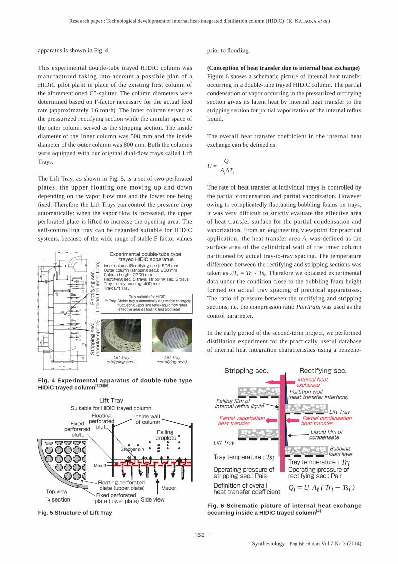
apparatus is shown in Fig. 4.
This experimental double-tube trayed HIDiC column was manufactured taking into account a possible plan of a HIDiC pilot plant in place of the existing first column of the aforementioned C5-splitter. The column diameters were determined based on F-factor necessary for the actual feed rate (approximately 1.6 ton/h). The inner column served as the pressurized rectifying section while the annular space of the outer column served as the stripping section. The inside diameter of the inner column was 508 mm and the inside diameter of the outer column was 800 mm. Both the columns were equipped with our original dual-flow trays called Lift Trays.
The Lift Tray, as shown in Fig. 5, is a set of two perforated plates, the upper f loat ing one moving up and down depending on the vapor flow rate and the lower one being fixed. Therefore the Lift Trays can control the pressure drop automatically: when the vapor flow is increased, the upper perforated plate is lifted to increase the opening area. The self-controlling tray can be regarded suitable for HIDiC systems, because of the wide range of stable F-factor values
prior to flooding.
(Conception of heat transfer due to internal heat exchange)Figure 6 shows a schematic picture of internal heat transfer occurring in a double-tube trayed HIDiC column. The partial condensation of vapor occurring in the pressurized rectifying section gives its latent heat by internal heat transfer to the stripping section for partial vaporization of the internal reflux liquid.
The overall heat transfer coefficient in the internal heat exchange can be defined as
U =Qi
AiΔTi
The rate of heat transfer at individual trays is controlled by the partial condensation and partial vaporization. However owing to complicatedly fluctuating bubbling foams on trays, it was very difficult to strictly evaluate the effective area of heat transfer surface for the partial condensation and vaporization. From an engineering viewpoint for practical application, the heat transfer area Ai was defined as the surface area of the cylindrical wall of the inner column partitioned by actual tray-to-tray spacing. The temperature difference between the rectifying and stripping sections was taken as Ti = Tri - Tsi. Therefore we obtained experimental data under the condition close to the bubbling foam height formed on actual tray spacing of practical apparatuses. The ratio of pressure between the rectifying and stripping sections, i.e. the compression ratio Pair/Pais was used as the control parameter.
In the early period of the second-term project, we performed distillation experiment for the practically useful database of internal heat integration characteristics using a benzene-
Fig. 4 Experimental apparatus of double-tube type HIDiC trayed column[2][5][9]
Fig. 5 Structure of Lift TrayFig. 6 Schematic picture of internal heat exchange occurring inside a HIDiC trayed column[2]
Tray suitable for HIDiC
Lift Tray: Stable tray automatically adjustable to largely fluctuating vapor and reflux liquid flow rates
(effective against fouling and blockade)
Lift Tray (rectifying sec.)
Lift Tray (stripping sec.)
Inner column (Rectifying sec.): 508 mmOuter column (stripping sec.): 800 mmColumn height: 2300 mmRectifying sec. 5 trays, stripping sec. 5 traysTray-to-tray spacing: 400 mmTray: Lift Tray
Experimental double-tube type trayed HIDiC apparatus
Rectifying sec.
(inside the inner tube)
Stripping sec.
(annular space)
Side view¼ sectionTop view
Stopper pin
Inside wall of column
Fixed perforated plate (lower plate)
Floating perforated plate (upper plate)
Fixed perforated plate
Floating perforated plate
Max.4
Falling droplets
Vapor
Suitable for HIDiC trayed columnLift Tray
Tray temperature :
Liquid film of condensate
Definition of overall heat transfer coefficient
Operating pressure of rectifying sec.: Pair
Operating pressure of stripping sec.: Pais
Lift Tray
Lift Tray
Partition wall(heat transfer interface)
Partial condensation heat transfer
Rectifying sec.Stripping sec.Internal heat exchange
Falling film of internal reflux liquid
Tray temperature :
Partial vaporization heat transfer
Bubbling foam layer
Qi = U Ai ( Tri - Tsi )
TriTsi

Research paper : Technological development of internal heat-integrated distillation column (HIDiC) (K. KATAOKA et al.)
−164−Synthesiology - English edition Vol.7 No.3 (2014)
toluene binary system as an ideal system of petrochemical hydrocarbon mixture, but in the later period, we devoted ourselves to an investigation of an ethanol-water system as a non-ideal system for a forthcoming challenging application to a bio-energy production process.[5][9][10]
As will be mentioned later, overlooking the experimental er ror and the scat ter ing data of overall heat t ransfer coefficient, it may be considered that the database should have a wide applicability by slight revision taking into account the effect of physical properties: the benzene-toluene data can be utilized for various hydrocarbons of usual molecular weight and the ethanol-water data could be utilized for various solution of water-soluble organic compounds such as methanol, propanol, acetaldehyde and MEK.
Our experiment was conducted by two operation modes: (1) pressurizing mode raising the rectifying section to higher than 1 atm (Pair > 1 atm and Pais = 1 atm) and (2) depressurizing mode lowering the stripping section to lower than 1 atm (Pair = 1 atm and Pais < 1 atm). The databases constructed with the control parameter of the compression ratio Pair/Pais are available both for the standard HIDiC and CF-HIDiC systems.
As an example, some of the data of internal heat exchange for the ethanol-water system are shown in Figs. 7 and 8.[5] Since boiling point rises with pressure, the characteristic temperature difference between the rectifying and stripping sections increases almost in proportion to the compression ratio. The correlation line of the pressurizing mode was different in slope from that of the depressurizing mode. The variation of the overall heat transfer coefficient was different between the pressurizing and depressurizing modes. It was confirmed that as the overall heat transfer coefficient for practical design, the underestimated value of U = 500 kcal/m2hr-ºC = 581.5 W/m2K should be recommended as a plant design on the safe side even for a clean ethanol-water system.
In the successive two projects (The second-term and third-term projects), the design database was constructed collecting
many experimental data of distillation accompanied with internal heat exchange.[5]
4 Enriching process of bioethanol – Research and development in the fourth-term project –
The HIDiC technology we developed did not spread among the petrochemical industry in spite of the assured great effect of energy saving. As our fourth-term project for breaking through the disadvantaged circumstances, we decided to join another NEDO project in order to boost the development of a new carbon neutral bioprocess producing biofuel ethanol.[6] This project was entitled “Development of environmentally benign and consolidated process for efficient production of cellulosic ethanol.” Our purpose was to boost their bioethanol distillation in the consolidated bio-processing process (called CBP process). The target allocated to the distillation team was (1) to enrich the fermented mash ethanol (5 wt% EtOH) to near azeotropic point (more than 90 wt%), and (2)to reduce the energy consumption required for distillation on dehydrated ethanol basis to 4 MJ/L-EtOH for the standard HIDiC. In the later period of the fourth-term project, the project committee members recognized CF-HIDiC to be safer and more promising and then approved the amended target of the energy consumption to 5 MJ/L-EtOH for the CF-HIDic.
4.1 Influence of the dirty non-volatile residues contained in fermented mashesExcept for the fermentation byproduct (e.g. acetic acid), the fermented mash liquid produced by the CBP process still contains non-volatile residues (e.g. saccharides, glucans, lignins, ashes) and enzyme proteins even after filtration pretreatment. We had a fouling problem as to how to prevent the fermentation residues from depositing by solidification reaction onto the heat transfer surfaces of the HIDiC stripping section and reboiler. For a preliminary check of fouling, a mash liquid fermented from rice straw was put into our original jacketed tank evaporator (named “Wall Wetter Evaporator”). We conducted the fouling test varying the operating pressure of the evaporator kettle. The inside wall of the evaporator kettle was assumed as the fouled
Compression ratio Pair/Pais (-)
DepressurizingPressurizing
43.532.521.510
5
10
15
20
25
30
Temperature difference
△T(K)
Compression ratio Pair/Pais (-)
DepressurizingPressurizing
43.532.521.510
500100015002000250030003500
Overall heat transfer
coefficient U (W/m
2K)
Fig. 7 Variation in temperature difference with compression ratio[5]
Fig. 8 Variation in overall heat transfer coefficient with compression ratio[5]
Research paper : Technological development of internal heat-integrated distillation column (HIDiC) (K. KATAOKA et al.)
−165−
Synthesiology - English edition Vol.7 No.3 (2014)
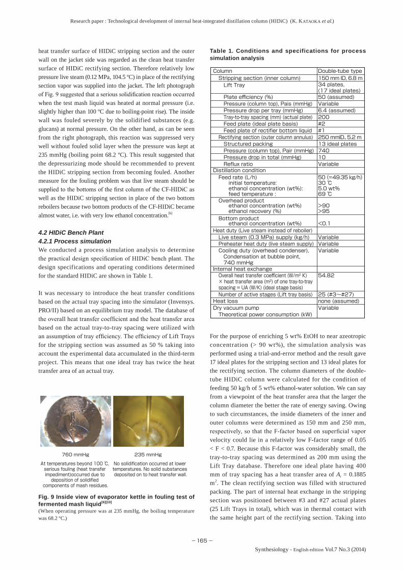
heat transfer surface of HIDiC stripping section and the outer wall on the jacket side was regarded as the clean heat transfer surface of HIDiC rectifying section. Therefore relatively low pressure live steam (0.12 MPa, 104.5 ºC) in place of the rectifying section vapor was supplied into the jacket. The left photograph of Fig. 9 suggested that a serious solidification reaction occurred when the test mash liquid was heated at normal pressure (i.e. slightly higher than 100 ºC due to boiling-point rise). The inside wall was fouled severely by the solidified substances (e.g. glucans) at normal pressure. On the other hand, as can be seen from the right photograph, this reaction was suppressed very well without fouled solid layer when the pressure was kept at 235 mmHg (boiling point 68.2 ºC). This result suggested that the depressurizing mode should be recommended to prevent the HIDiC stripping section from becoming fouled. Another measure for the fouling problem was that live steam should be supplied to the bottoms of the first column of the CF-HIDiC as well as the HIDiC stripping section in place of the two bottom reboilers because two bottom products of the CF-HIDiC became almost water, i.e. with very low ethanol concentration.[6]
4.2 HIDiC Bench Plant4.2.1 Process simulationWe conducted a process simulation analysis to determine the practical design specification of HIDiC bench plant. The design specifications and operating conditions determined for the standard HIDiC are shown in Table 1.
It was necessary to introduce the heat transfer conditions based on the actual tray spacing into the simulator (Invensys. PRO/II) based on an equilibrium tray model. The database of the overall heat transfer coefficient and the heat transfer area based on the actual tray-to-tray spacing were utilized with an assumption of tray efficiency. The efficiency of Lift Trays for the stripping section was assumed as 50 % taking into account the experimental data accumulated in the third-term project. This means that one ideal tray has twice the heat transfer area of an actual tray.
For the purpose of enriching 5 wt% EtOH to near azeotropic concentration (> 90 wt%), the simulation analysis was performed using a trial-and-error method and the result gave 17 ideal plates for the stripping section and 13 ideal plates for the rectifying section. The column diameters of the double-tube HIDiC column were calculated for the condition of feeding 50 kg/h of 5 wt% ethanol-water solution. We can say from a viewpoint of the heat transfer area that the larger the column diameter the better the rate of energy saving. Owing to such circumstances, the inside diameters of the inner and outer columns were determined as 150 mm and 250 mm, respectively, so that the F-factor based on superficial vapor velocity could lie in a relatively low F-factor range of 0.05 < F < 0.7. Because this F-factor was considerably small, the tray-to-tray spacing was determined as 200 mm using the Lift Tray database. Therefore one ideal plate having 400 mm of tray spacing has a heat transfer area of Ai = 0.1885 m2. The clean rectifying section was filled with structured packing. The part of internal heat exchange in the stripping section was positioned between #3 and #27 actual plates (25 Lift Trays in total), which was in thermal contact with the same height part of the rectifying section. Taking into
Table 1. Conditions and specifications for process simulation analysis
Fig. 9 Inside view of evaporator kettle in fouling test of fermented mash liquid[6][10]
(When operating pressure was at 235 mmHg, the boiling temperature was 68.2 ºC.)
VariableDry vacuum pumpnone (assumed)Heat loss25 (#3~#27)Number of active stages (Lift tray basis)
54.82Overall heat transfer coefficient (W/m2 K) × heat transfer area (m2) of one tray-to-tray spacing = UA (W/K) (ideal stage basis)
Internal heat exchange
VariableCooling duty (overhead condenser), Condensation at bubble point, 740 mmHg
VariablePreheater heat duty (live steam supply)VariableLive steam (0.3 MPa) supply (kg/h)
Heat duty (Live steam instead of reboiler)<0.1ethanol concentration (wt%)
Bottom product
>90>95
ethanol concentration (wt%)ethanol recovery (%)
Overhead product
30 ℃5.0 wt%69 ℃
50(=49.35 kg/h)Feed rate (L/h)Distillation condition
VariableReflux ratio10Pressure drop in total (mmHg)740Pressure (column top), Pair (mmHg)13 ideal platesStructured packing250 mmID、5.2 mRectifying section (outer column annulus)#1Feed plate of rectifier bottom liquid#2Feed plate (ideal plate basis)200Tray-to-tray spacing (mm) (actual plate)6.4 (assumed)Pressure drop per tray (mmHg)VariablePressure (column top), Pais (mmHg)50 (assumed)Plate efficiency (%)
34 plates,(17 ideal plates)
Lift Tray150 mm ID, 6.8 mStripping section (inner column)Double-tube typeColumn
initial temperature:ethanol concentration (wt%):feed temperature :
Theoretical power consumption (kW)
760 mmHg 235 mmHg
At temperatures beyond 100 ℃, serious fouling (heat transfer impediment)occurred due to deposition of solidified
components of mash residues.
No solidification occurred at lower temperatures. No solid substances deposited on to heat transfer wall.
Research paper : Technological development of internal heat-integrated distillation column (HIDiC) (K. KATAOKA et al.)
−166−Synthesiology - English edition Vol.7 No.3 (2014)
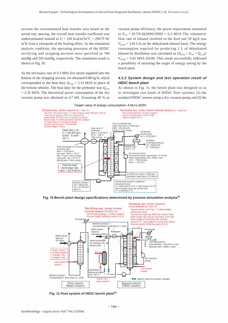
account the overestimated heat transfer area based on the actual tray spacing, the overall heat transfer coefficient was underestimated instead as U = 250 kcal/m2hrºC = 290.75 W/m2K from a viewpoint of the fouling effect. As the simulation analysis condition, the operating pressures of the HIDiC rectifying and stripping sections were specified as 740 mmHg and 210 mmHg, respectively. The simulation result is shown in Fig. 10.
As the necessary rate of 0.3 MPa live steam supplied into the bottom of the stripping section, we obtained 0.88 kg/h, which corresponded to the heat duty QSTM = 2.15 MJ/h in place of the bottom reboiler. The heat duty for the preheater was Qpreh = 2.35 MJ/h. The theoretical power consumption of the dry vacuum pump was obtained as 0.7 kW. Assuming 40 % as
vacuum pump efficiency, the power requirement amounted to EVP = (0.7/0.4)(3600/1000) = 6.3 MJ/h The volumetric f low rate of ethanol involved in the feed rate 50 kg/h was VEtOH = 3.16 L/h on the dehydrated ethanol basis. The energy consumption required for producing 1 L of dehydrated ethanol by distillation was calculated as (QSTM + EVP + Qpreh)/VEtOH = 3.42 MJ/L-EtOH. This result successfully indicated a possibility of attaining the target of energy saving by the bench plant.
4.2.2 System design and test operation result of HIDiC bench plantAs shown in Fig. 11, the bench plant was designed so as to investigate two kinds of HIDiC f low systems: (1) the standard HIDiC system using a dry vacuum pump and (2) the
Fig. 10 Bench plant design specifications determined by process simulation analysis[6]
Fig. 11 Flow system of HIDiC bench plant[6]
Target value of energy consumption: 4 MJ/L-EtOH
Overall heat transfer coefficient (assumed value)U = 290.8 W/m^2 K (= 250 kcal/m^2 h℃Heat transfer area (per actual tray)A = 0.09426 m^2
Structured packing (13 ideal stages)Column top pressure: 740 mmHgColumn height: 5.2 m
Rectifying sec. (outer column annular space) Do = 250 mmLift Tray: 34 actual trays (17 ideal stages, plate efficiency: 50 %)Tray-to-tray spacing: 200 mm (actual tray)Feed stage: #3 (from top on actual tray basis)Feed stage of rectifying section bottom product: #1 (top stage on actual tray basis)Column top pressure: 210 mmHgColumn height: 6.8 m
Stripping sec. (inner column) Di = 150 mm
#3
#1
Bottom productXw = 66.8 ppmW = 47.65 kg/h68.4 ℃
Distillate (overhead product)xD = 93.63 wt%D = 2.58 kg/hReflux ratio:
R/R = 1.0
Internal heat exchange rateQint = 23.3 MJ/h
CondenserCooling dutyQc = -4.90 MJ/h
0.3 MPa live steam: 0.88 kg/hEquivalent heat duty: 2.15 MJ/h
Feed (50 L/h)F = 49.35 kg/hEtOH:5 wt%30 ℃
Heat exchanger for recovery of waste heatQhrc = 5.54 MJ/hHot side:68.4 → 40 ℃46.77 kg/h(760 mmHg)Cold side:30 → 57.4 ℃49.35 kg/h(760 mmHg)
Heat duty of preheaterQpre = 2.35 MJ/h57.4 → 69 ℃760 mmHg
Dry vacuum pumpTheoretical power requirement 0.70 kWVapor discharging rate: 1062 L/min210 → 750 mmHg60.6 → 137.9 ℃
Top of stripping sec.Vapor flow rate =18.95 kg/hEtOH:63.43 wt%57.6 ℃、210 mmHg
Switch valve for system change
Condenser
Second column(HIDiC column)
First column(Mash column)
Live steam supply
Mash liquid feed for CF-HIDiC
Mash column8 ideal stagesChange Tray(original tray)
Bottom productConcentration less than 0.1 wt%
Steam
Sterilization by heating at higher than 120 ℃Bottom product
Concentration less than 0.1 wt% Vapor from mash column
Dry vacuum pump
Overhead productConcentration = 90 wt% or moreRecovery rate = 95% or moreR
eflux
Condenser
Live steam supply
Mash liquid feed for standard HIDiC
Heat exchanger for recovery of waste heat
Preheater
Rectifying sec. (outer column annular space) Do=250 mm Structured packing (13 ideal stages) Column height (effective part): 5.2 m
Stripping sec. (inner column) Inside diameter Di=150 mm Trayed column (Lift Tray): 17 ideal stages (34 actual trays) Tray-to-tray spacing: 200 mm (actual tray) Feed stage: #3 (actual tray basis from top) Feed stage of rectifying sec. bottom product: #1 (top stage on actual tray basis) Column height (effective part): 6.8 m
#3
#1
Sterilizer

Research paper : Technological development of internal heat-integrated distillation column (HIDiC) (K. KATAOKA et al.)
−167−
Synthesiology - English edition Vol.7 No.3 (2014)
compressor-free HIDiC system consisting of two columns: the first one was an ordinary column and the second one was a HIDiC main column. The project committee recognized the CF-HIDiC system as promising for a large-scale commercial plant, and recommended to add it to the project plan.
(1) Standard HIDiCFigure 12 shows a flow system for the standard HIDiC used in the bench plant. In the early period, the main plan of our team was to investigate the standard HIDiC because of its great energy saving effect. Being distinct from a usual HIDiC system, the stripping section was placed into the inner column for maintenance of removing solidified substances and residues from fouled trays. The clean rectifying section filled with structured packing was placed into the annular space of the outer column. The stripping section was
equipped with our Lift Trays for prevention against tray blockade. We had to conduct the test operation of the bench plant using a simulated mash liquid owing to the fact that the bioprocess team had not yet reached the stage of full production. As shown in Fig. 13, we obtained a satisfactory result of the standard HIDiC test operation at a small ref lux ratio of 0.378 when the stripping section was depressurized to 225 mmHg with the rectifying section kept at normal pressure. The result satisfying the project target can be summarized as follows: (1) sufficient ethanol concentration of overhead product of 94.4 wt%, i.e. higher than the project target (> 90 wt%) with reflux ratio of 0.378, (2) large recovery rate of 95.4 % of ethanol contained in the feed, i.e. higher than the project target (> 95 %), (3) sufficiently low ethanol concentration of
Fig. 12 Structure of standard HIDiC bench plant[6][7][10]
Bottom product
Feed
Heat exchanger for recovery of waste heat
Rectifying sec. (outer column annular space)Structured packingAnnular space:250 mm OD and 150 mm IDRectifying sec. column height: 5.2 m(internal heat exchange area: 5.0 m)
Flash drumTotal condenser
Live steam supply
Dry screw vacuum pumpRated active power: 7.5 kWVapor discharge rate: 2800 L/min
Preheater
Stripping sec. (inner column)Lift Tray (dual-flow tray without weir)Inner column diameter: 150 mm ID17 ideal stages (34 actual trays)Actual tray-to-tray spacing: 200 mmStripping sec. column height: 6.8 mInternal heat exchange trays: #3~#27
Internal heat exchange trays: #3 ~#27 (actual trays)Heat transfer area per actual trayA = 0.09426 m2Temperature difference (averaged) ΔT = 8.05 ℃Actual overall heat transfer coefficientU = Qint/(25 A ΔT) = 325.2 W/m2K(value assumed for design: U = 290.75 W/m2K)
Internal heat exchange trays: #3 ~#27 (actual trays)Heat transfer area per actual trayA = 0.09426 m2Temperature difference (averaged) ΔT = 8.05 ℃Actual overall heat transfer coefficientU = Qint/(25 A ΔT) = 325.2 W/m2K(value assumed for design: U = 290.75 W/m2K)
Reflux ratio = 0.378Reflux ratio = 0.378
Energy consumption: 2.86 MJ/L-EtOH < 4 MJ/L-EtOH (target value)
Heat loss :Qloss = 1.28 MJ/h
105.9 ℃
100.9 ℃
Distillate (overhead product)D = 2.54 kg/hEtOH:94.4 wt%24.4 ℃
Vapor from top of rectifying sec.V2 = 3.50 kg/h94.4 wt%、77.4 ℃
Stripping sec. bottom productW1 = 47.73 kg/h0.024 wt%、86.9 ℃
40 ℃
Feed preheaterSteam consumption (0.12 MPa)STM2 = 3.28 kg/hQpr2 = 7.37 MJ/h104.2 ℃
Feed preheaterSteam consumption (0.12 MPa)STM2 = 3.28 kg/hQpr2 = 7.37 MJ/h104.2 ℃
Live steam (0.12 MPa)supply rateSTM1 = 0 kg/h104.2 ℃
Live steam (0.12 MPa)supply rateSTM1 = 0 kg/h104.2 ℃
Stripping sec. (inner column)Operating pressure: 225 mmHgStripping sec. (inner column)Operating pressure: 225 mmHg
Dry screw vacuum pumpActual power consumptionPw = 0.516 kW = 1.86 MJ/h
FeedF = 50.27 kg/hEtOH:5 wt%19 ℃
Heat transfer rate of internal heat exchangeQint = 22.19 MJ/h
Rectifying sec. bottom productW2 = 10.80 kg/h1.14 wt%、95.7 ℃
Rectifying sec. (outer column annular space)Operating pressure: 760 mmHg
RefluxR2 = 0.96 kg/h24.4 ℃(sub-cooled)
RefluxR2 = 0.96 kg/h24.4 ℃(sub-cooled)
Vapor from top of stripping sec.V1 = 13.34 kg/h、29.73 wt%70.1 ℃ (225 mmHg)
Fig. 13 Test run result of standard HIDiC bench plant[6][7][10] (obtained when Pair = 760 mmHg and Pais = 225 mmHg)
Research paper : Technological development of internal heat-integrated distillation column (HIDiC) (K. KATAOKA et al.)
−168−Synthesiology - English edition Vol.7 No.3 (2014)
the bottom product of 0.024 wt%, i.e. lower than the target (< 0.1 wt%), and (4) no supply of live steam into the bottom of the stripping section (QSTM = 0 kg/h). This implies that the standard HIDiC column could be driven only by the dry vacuum pump without any heat duty. The electric energy actually consumed by the dry vacuum pump was EVP = 0.516 kW = 1.86 MJ/h. In this case, a heat duty of the preheater was required as Qpreh = 7.37 MJ/h. The total energy consumption amounted to Qtotal = QSTM + EVP + Qpreh = 9.23 MJ/h. As the energy consumption required for producing 1 L ethanol on dehydrated ethanol basis, Qtotal/VEtOH = 9.23/3.16 = 2.87 MJ/L-EtOH. This result was sufficiently smaller than the project target (4 MJ/L-EtOH).
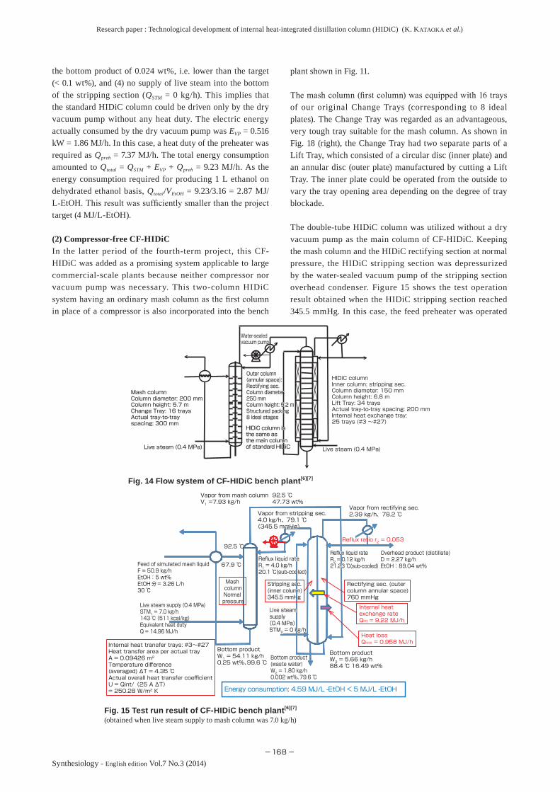
(2) Compressor-free CF-HIDiCIn the latter period of the fourth-term project, this CF-HIDiC was added as a promising system applicable to large commercial-scale plants because neither compressor nor vacuum pump was necessary. This two-column HIDiC system having an ordinary mash column as the first column in place of a compressor is also incorporated into the bench
plant shown in Fig. 11.
The mash column (first column) was equipped with 16 trays of our original Change Trays (corresponding to 8 ideal plates). The Change Tray was regarded as an advantageous, very tough tray suitable for the mash column. As shown in Fig. 18 (right), the Change Tray had two separate parts of a Lift Tray, which consisted of a circular disc (inner plate) and an annular disc (outer plate) manufactured by cutting a Lift Tray. The inner plate could be operated from the outside to vary the tray opening area depending on the degree of tray blockade.
The double-tube HIDiC column was utilized without a dry vacuum pump as the main column of CF-HIDiC. Keeping the mash column and the HIDiC rectifying section at normal pressure, the HIDiC stripping section was depressurized by the water-sealed vacuum pump of the stripping section overhead condenser. Figure 15 shows the test operation result obtained when the HIDiC stripping section reached 345.5 mmHg. In this case, the feed preheater was operated
HIDiC column is the same as the main column of standard HIDiC
HIDiC column is the same as the main column of standard HIDiC Live steam (0.4 MPa)Live steam (0.4 MPa)Live steam (0.4 MPa)
Water-sealed vacuum pump
Outer column (annular space):Rectifying sec.Column diameter: 250 mmColumn height: 5.2 mStructured packing8 ideal stages
Outer column (annular space):Rectifying sec.Column diameter: 250 mmColumn height: 5.2 mStructured packing8 ideal stages
HIDiC columnInner column: stripping sec.Column diameter: 150 mmColumn height: 6.8 mLift Tray: 34 traysActual tray-to-tray spacing: 200 mmInternal heat exchange tray: 25 trays (#3 ~#27)
Mash columnColumn diameter: 200 mmColumn height: 5.7 mChange Tray: 16 traysActual tray-to-tray spacing: 300 mm
Mash columnColumn diameter: 200 mmColumn height: 5.7 mChange Tray: 16 traysActual tray-to-tray spacing: 300 mm
Internal heat exchange rateQint = 9.22 MJ/h
Internal heat transfer trays: #3~#27Heat transfer area per actual trayA = 0.09426 m2Temperature difference (averaged) ΔT = 4.35 ℃Actual overall heat transfer coefficientU = Qint/(25 A ΔT)= 250.28 W/m2 K
Heat lossQloss = 0.958 MJ/h
92.5 ℃
67.9 ℃
Vapor from rectifying sec.2.39 kg/h、78.2 ℃
Bottom productW3 = 5.66 kg/h88.4 ℃ 16.49 wt%
Energy consumption: 4.59 MJ/L -EtOH < 5 MJ/L -EtOH
Live steam supply(0.4 MPa)STM2 = 0 kg/h
Live steam supply(0.4 MPa)STM2 = 0 kg/h
92.5 ℃47.73 wt%
Vapor from stripping sec.4.0 kg/h、79.1 ℃(345.5 mmHg)
Vapor from stripping sec.4.0 kg/h、79.1 ℃(345.5 mmHg)
Mash columnNormal pressure
Vapor from mash column V1 =7.93 kg/h
Live steam supply (0.4 MPa)STM1 = 7.0 kg/h143 ℃ (511 kcal/kg)Equivalent heat duty Q = 14.96 MJ/h
Stripping sec. (inner column)345.5 mmHg
Stripping sec. (inner column)345.5 mmHg
Rectifying sec. (outer column annular space)760 mmHg
Bottom productW1 = 54.11 kg/h0.25 wt%、99.6 ℃
Reflux liquid rateR1 = 4.0 kg/h20.1 ℃(sub-cooled)
Reflux liquid rateR1 = 4.0 kg/h20.1 ℃(sub-cooled)
Reflux liquid rateR2 = 0.12 kg/h21.23 ℃(sub-cooled)
Reflux liquid rateR2 = 0.12 kg/h21.23 ℃(sub-cooled)
Overhead product (distillate)D = 2.27 kg/hEtOH: 89.04 wt%
Bottom product (waste water)W2 = 1.80 kg/h0.002 wt%、79.6 ℃
Feed of simulated mash liquidF = 50.9 kg/hEtOH: 5 wt%EtOH分= 3.26 L/h30 ℃
Reflux ratio r2 = 0.053
Fig. 14 Flow system of CF-HIDiC bench plant[6][7]
Fig. 15 Test run result of CF-HIDiC bench plant[6][7] (obtained when live steam supply to mash column was 7.0 kg/h)

Research paper : Technological development of internal heat-integrated distillation column (HIDiC) (K. KATAOKA et al.)
−169−
Synthesiology - English edition Vol.7 No.3 (2014)
by utilizing the thermal energy of the mash column bottom product as waste heat. The rate of 0.4 MPa live steam supplied into the mash column bottom amounted to 7.0 kg/h corresponding to QSTM1 = 14.95 MJ/h as the heat duty.
The HIDiC main column was successfully operated with no live steam supply owing to a great effect of internal heat exchange. This means that the heat duty of the HIDiC main column became QSTM2 = 0 MJ/h. As a result, the whole CF-HIDiC system was successfully operated by the live steam supply for the mash column only: Qtotal = QSTM1 = 14.95 MJ/h.
Taking into account the volumetric feed rate of ethanol VEtOH = 3.26 L/h, the energy consumption required for the whole CF-HIDiC system amounted to Qtotal/VEtOH = 4.59 MJ/L-EtOH on dehydrated ethanol basis. This value suggested that the project target (< 5 MJ/L-EtOH) was successfully achieved. However as can be seen from Fig. 15, the ethanol concentration 0.25 wt% of the mash column bottom product went beyond the eff luent control value (0.1 wt%) and the overhead product concentration 89.04 wt% became a little bit lower than the project target (> 90 wt%). We had to gradually increase the rate of live steam supply into the mash column from 7.0 kg/h.
Figure 16 indicates that we obtained an optimum result satisfying both the energy-saving target and the enriching target when the live steam supply was raised to 10.55 kg/h. The CF-HIDiC test operation was a big success with the following results: (1) energy consumption of 5.09 MJ/L-EtOH was almost on par with the project target (5 MJ/L-EtOH), (2) overhead product concentration of 92.2 wt% EtOH and the two bottom product concentrations 0.01 wt% and almost 0 wt% satisfied the respective target values (> 90 wt% and < 0.1 wt% EtOH), and (3) recovery rate of 95.8 % of ethanol contained in
the feed was also larger than the target value (95 %).
Finally the photograph of the bench plant is shown in Fig. 17, where the right-side column is the first column (mash column) and the left-side one is the double-tube HIDiC trayed column. Figure 18 shows the internal structures of the two columns: the left photograph indicates a Lift Tray installed into the stripping section and structured packing installed in the rectifying section; and the right photograph indicates the Change Tray equipped into the mash column. The upper plate of the Lift Tray had an opening of square holes while the lower fixed plate had circular drilled holes. Considering the variation of vapor rate with the height of the HIDiC stripping section, the number of holes of the Lift Trays was adjusted.
5 Conclusion
Starting with a project of the New Sunshine Program “the fundamental research on energy saving distillation technology by internal heat integration,” we participated in three successive NEDO projects spanning over more than ten years. The useful outcome obtained by this substantive research suggests that the road to commercialization is not a long way off.
In spite of the great effect of energy-savings, the HIDiC technology still did not spread in the chemical industry. This is due to the fact that usual steam temperature level of the heat source for distillation is not so high to try an improvement of distillation processes from a viewpoint of energy conservation. The standard HIDiC is suitable to clean distillation processes because of its great effect of energy savings. However a technological problem still remains as to whether or not a big compressor is necessary for a large
Energy consumption:5.09 MJ/L-EtOH
Heat lossQloss= 0.62 MJ/h
Live steam supply(0.12 MPa)STM2 = 0 kg/h
67.3 ℃
Vapor from stripping sec.V2-2 = 3.86 kg/h、15.26 wt%75.1 ℃(309 mmHg)
Mash columnNormal pressure
Waste heat effectively usedBottom product = 56.92 kg/h40 ℃
Vapor from mash columnV1 = 9.53 kg/h27.87 wt%96.5 ℃
Internal heat exchange rateQint = 7.632 MJ/h
Waste heat unutilizedBottom product = 20.54 kg/h
Live steam supply (0.12 MPa)STM1 = 10.55 kg/h104.2 ℃
Rectifying sec.Bottom productW3 = 5.76 kg/h4.57 wt%、 95.6 ℃
Stripping sec. (inner column)309 mmHg
Rectifying sec. (outer column annular space)760 mmHg
Bottom productW1 = 77.46 kg/h0.01 wt%、100.3 ℃
Reflux liquid rateR1 = 3.86 kg/h15.26 wt%19 ℃(sub-cooled)
Vapor from rectifying sec.V2-1 = 4.40 kg/h92.2 wt%、77.7 ℃
Reflux liquid rateR2 = 0.63 kg/h20.8 ℃(sub-cooled)
Overhead product (distillate)D = 3.77 kg/hEtOH:92.2 wt%20.8 ℃
Bottom product (waste water)W2 = 1.90 kg/h0 wt%、 84.4 ℃
Feed of simulated mash liquidF = 72.58 kg/hEtOH:5 wt%19 ℃
Fig. 16 Test run result of CF-HIDiC bench plant[6] (obtained when live steam supply to mash column was 10.55 kg/h)

Research paper : Technological development of internal heat-integrated distillation column (HIDiC) (K. KATAOKA et al.)
−170−Synthesiology - English edition Vol.7 No.3 (2014)
discharging rate of distilled vapor. At the present time, in particular, there is not an appropriate vacuum pump available for the depressurizing mode. It can be considered that the CF-HIDiC with no compressor is appropriate for large-scale distillation plants. We are expecting wide spread use of CF-HIDiC in various fields of the chemical industry.
AcknowledgmentsThis research was conducted through the following successive projects supported by the New-Energy and Industrial Technology Development Organization (NEDO), Japan
NEDO project No.P02020: Eco-energy distillation technological development by internal heat integration (FY2002 – FY2005)
NEDO project No.P09015: Strategic development of energy conversion technology/research and development of basic technologies for an internally heat integrated distillation column compressor-free system (FY2008 – FY2010)
NEDO project No.P07015: Development of environmentally benign and consolidated process for efficient production of cellulosic ethanol (FY2008 – FY2010)
We would like to express our gratitude to AIST (National
Institute of Advanced Industrial Science and Technology) for the valuable advice given in the early period of constructing the HIDiC database.
This project was successfully shortlisted as one of the five candidates for the best project of the year 2013 in the global awards of IChemE, UK.
Fig. 17 Bench plant of CF-HIDiC under installation[10] mash column (right) and HIDiC main column (left)
Fig. 18 Internal structure of mash column (right) and HIDiC main column (left)[10]
Lift Tray type of Change Tray (right) and Lift Tray (inner column) and structured packing (annular space) (left)
References
[1] M. Nakaiwa and T. Ohmori: Innovation in distillation processes, Synthesiology, 2 (1), 51-59 (2009) (in Japanese) [Synthesiology English edition, 1 (1), 55-63 (2009)].
[2] NEDO Project: Naibu-netsu-kokan ni yoru sho-ene joryu gijutsu-kaihatsu (Technological development of energy-saving distillation column by internal heat integration) (Project No. P02020), (FY2002 – FY2005), Final Report (2006) (in Japanese).
[3] K. Horiuchi, K. Yanagimoto, K. Kataoka and M. Nakaiwa: Energy-saving characteristics of heat integrated distillation column technology applied to multi-component petroleum distillation, Distillation & Absorption 2006, Inst. Chem. Eng. Symp. Ser., 152, 172-180 (2006).
[4] Patent No.4819756 (2011): Taseibunkei naibu-netsukokan-shiki joryu-sochi (Internal heat integrated distillation system for multi-component distillation).
[5] NEDO Project: Enerugi shiyo gorika gijutsu senryakuteki kaihatsu/Asshukuki o hitsuyo to shinai naibu-netsu-kokan-shiki joryu shisutemu no kiban-gijutsu no kenkyu-kaihatsu (Strategic development of energy conservation technology/research and development of basic technologies for an internally heat integrated distillation column compressor-free system (Successive research phase) (Project No.09015)(FY2008 - FY2010) Final Report (2011) (in Japanese).
[6] NEDO Project: Serurosu etanoru ko-koritsu seizo no tameno kankyo-chowagata togo purosesu kaihatsu (Development of environmentally benign and consolidated process for efficient production of cellulosic ethanol) (No.P07015) (FY2008 – FY2010) Final Report (2011) (in Japanese).
[7] K. Kataoka, H. Noda, H. Yamaji, T. Mukaida, K. Kurata, M. Kaneda and G. Nishimura: Baio-etanoru noshuku no tameno asshukuki fuyo no HIDiC --- Benchi puranto ni yoru jissho kenkyu (Substantive research on a compressor-free HIDiC bench plant for enrichment of bioethanol), Autumnal Meeting of SCEJ, M108 & 109, Okayama, September 16-18 (2013) (in Japanese).
[8] R. S. H. Mah, J. J. Nicholas Jr. and R. B. Wodnik: Distillation with secondary ref lux and vaporization: A comparative evaluation, AIChE Journal, 23 (5), 651-658 (1977).
[9] H. Noda, K. Kataoka, H. Yamaji and N. Kuratani: Heat transfer and f low characteristics of a double-tube HIDiC trayed column, 8th World Congress of Chemical Engineering, energy 0064, Montreal, August 23-27 (2009).
[10] K. Kataoka, H. Noda, T. Mukaida, G. Nishimura and H. Yamaji: Boost to bioethanol distillation by internal heat-integrated distillation column (HIDiC), Advanced Chemical Engineering Research (ACER), 3, 48-57 (2014).
Research paper : Technological development of internal heat-integrated distillation column (HIDiC) (K. KATAOKA et al.)
−171−
Synthesiology - English edition Vol.7 No.3 (2014)
Authors
Kunio KATAOKAGraduated from Department of Chemical Engineer ing of Kyoto University in March 1963. Completed the courses at Graduate School of Engineering, Kyoto University in March 1968. Doctor of Engineer ing. Assistant Professor of Chemical Engineer ing Depar tment, Kobe University in April 1968. Associate Professor, Kobe University in May 1971. Invited Professor, Department of Chemical Engineering, Louisiana State University in August 1978. Full Professor, Kobe University in October 1988. The Dean of Engineering, Kobe University in April 1994. The Vice President of Kobe University in February 1997. The President of the Society of Chemical Engineers, Japan (SCEJ) in April 2000. Won the Award of Science of Hyogo Prefecture in November 2001. Won the SCEJ award 2003 from the Society of Chemical Engineers, Japan in 2003. After retirement from Kobe University in 2013, joined Kansai Chemical Engineering Co., Ltd. (KCE) as the Executive Director in April 2003. Currently, Director of R&D Laboratory of KCE and Executive Director of Bio-energy Corporation. Executed NEDO HIDiC projects P02020, P09015 and P07015 successively from 2003 to 2011. Interested in the fields of transport science and heat transfer both for research and education in Kobe University period. Now interested in the development of energy conservation technologies in chemical engineering processes in the present KCE period. Honorary members of SCEJ and HTSJ (Heat Transfer Society of Japan). In this paper, contributed to development of CF-HIDiC as chief leader of the third-term project. Contributed not only to basic technological development and database construction of HIDiC but also to practical design of the HIDiC bench plant based on the specifications and operating conditions determined by process simulation analysis. Contributed to the negotiation with other project teams for fixing up all the targets of individual sub-teams for the objective of the whole Biofuel Challenge NEDO project.
Hideo NODAGraduated from Department of Physics, Osaka University in March 1970. After joining Kansai Chemical Engineering Co., Ltd. (KCE) in 1970, completed the courses at Graduate School of Chemical Engineering, Osaka University in March 1975. Doctor of Engineering. Visiting researcher, University of Leeds from 1979 to 1981. President of KCE in 1993. In addition, founded Bio-energy Corporation as President in 2001. Won the Award of Science of Hyogo Prefecture in November 2011. Currently a Director of SCEJ from 2013. Interested in various distillation technologies, HIDiC, Wall-Wetter, crystallization and biofuel processes and systems from 1990. Executed this NEDO project of bioethanol production process as the project sub-organizer, researching bio-reactors from 2001. Won many various awards of technologies from SCEJ and SSPEJ (The Society of Separation Process Engineers, Japan). In this paper, as the sub-organizer of NEDO project No.P02020, responsible for allotting individual energy consumption as project targets to all the sub-processes
producing bioethanol. Members of SCEJ, SSEJ, SBJ (The Society for Biotechnology, Japan) and others.
Discussions with Reviewers
1 OverallComment (Yasuo Hasegawa, AIST Kansai, and Akira Kageyama, Research and Innovation Promotion Headquarters, AIST)
Focusing their attention on distillation technology as the main separation process in chemical industry, the authors executed successive NEDO projects for ten years for the development of the internal heat integrated distillation column (HIDiC) in expectation of a great effect of energy conservation. They successfully broke through a barrier against spreading of the standard HIDiC by analyzing its negative factor. This paper describing the process of how to execute their successive projects for the research and development based on a definite scenario is suitable for Synthesiology and is useful to researchers in other fields.
In order to achieve the pr imary purpose and project target, they not only realized a collaborat ion of process system engineering with heat transfer engineering for mutual complementation of different technological f ields but also proposed cooperation with the team of saccharification and fermentation.
We judge this paper to be full of suggestions on methodology of research and development and project management.Answer (Kunio Kataoka, KCE)
Responding to the objective of Synthesiology, the reviewers advised us to rearrange the chapters of the paper from a viewpoint of methodology as to how to execute projects for breakthroughs. We rewrote the paper complying to the purport of their questions and comments. This successful accomplishment was not only due to the fact that these successive ten year-lasting projects were accepted by NEDO but also due to the valuable discussions and advice given by various professors and researchers from a wide range of scientific fields.
It was good that we courageously acknowledged our inexpertness and collaborated with researchers of different fields, and created an atmosphere of active discussion at project meetings with researchers from various fields. We would like to emphasize that the way to command a big project is to synthesize comprehensively with the collaboration of people from many different fields.
2 Technological issue of distillation for clean and dirty servicesQuestion (Yasuo Hasegawa)
We always ask authors to rewrite their papers along the purport of Synthesiology, so that inexperienced readers from different f ields can understand as much as possible. If the authors supplement the following, the paper will become more comprehensible.
In the second-term project, a packed-column type HIDiC system allotted by Kimura Chemical Plants was adopted as a candidate of the pilot plant. At that stage, how was the packed-column HIDiC system evaluated in relation to the development level? What was regarded as a clean service of distillation? What degree of energy saving was expected? What was a dirty service of distillation which is covered in this paper? We want you to give some explanations why the packed-column system could not be used for a dirty service. In addition, an original idea leading to HIDiC was proposed by Dr. Mah et al. In spite of that, their paper was hardly noted and was not followed by anybody. Why

Research paper : Technological development of internal heat-integrated distillation column (HIDiC) (K. KATAOKA et al.)
−172−Synthesiology - English edition Vol.7 No.3 (2014)
was their paper left buried? We would like to know what kind of technological difficulty caused such a resigned situation.Answer (Kunio Kataoka)
Taking into consideration these questions, we rewrote this paper with some additions and modifications. First of all, the first- and second-term projects were started with investigation of a packed-column type HIDiC system, because most of the leading investigations of distillation were preceded by universities and their experimental data of packed-column distillation were rich in content. Regarding the clean service of distillation, therefore, if the hydrocarbon mixtures mostly treated in petrochemical industry contain neither distillation residues (e.g. pitches) nor polymerizable substances, there is not any fear of corrosion, solid deposition and blockade of internal packing. Then a packed-column type HIDiC system was regarded as the most reliable candidate for an HIDiC pilot plant.
On the other hand, regarding the dirty service of distillation, there are various kinds of feed mixtures for distillation. For example, the dirty mixtures very often contain intrinsically solid suspended substances (e.g. pigments, catalysts, carbonized substances, ashes, etc.). A solution including monomers not only may increase in viscosity during the distillation process but may also cause tray blockade owing to the polymerization or solidification reaction. There also is another dirty mixture containing dissolved inorganic salts (e.g. calcium sulfate) which produces crystal particles depositing on heat transfer surfaces when temperature rises. These mixtures have a fear of blocking internal packing which makes the maintenance of a packed-column type HIDiC system impossible. This situation aroused our interest in the need of development of another type of HIDiC system. Although we did not make an analysis strictly investigating why Dr. Mar et al. paper was left buried, we extracted the following factors: (1) their paper was presented at a place not noticeable for researchers in the distillation engineering field, (2) distillation engineers were not inexperienced and felt uncomfortable about mechanically compressing a large volume of vapor in the distillation process when considering preventive measures for fire, and (3) their paper written using a block diagram of black boxes from a viewpoint of process system engineering did not show a practical image of the system structure of internal heat integration. Therefore we may say that at that time, distillation engineers were not able to figure out any possibility of realization.
3 Originality of developed technologyQuestion (Akira Kageyama)
This paper mentions that it was an original idea to reflux a condensate produced at the overhead condenser of the HIDiC stripping section to the top of the first column. You also describe that your original Lift Trays were placed in the second column of the CF-HIDiC system. Does this mean that no similar equipment had been in existence up to that time? We would like you to discuss the originality of the developed technology in more detail. Answer (Kunio Kataoka)
We added some postscripts to the paper in relation to this question. In the stripping section of the HIDiC column, the upward flowing vapor is increased owing to the partial vaporization due to the internal heat exchange in order to reduce the heat duty of the bottom reboiler. Nevertheless the vapor arriving at the top of the stripping section is condensed purposely by the overhead condenser. Many contrary opinions were expressed pointing out that the idea of an overhead condenser of the stripping section was against the rule of the original HIDiC concept. We repeated the following explanation in relation to the origin of our idea. The first column of CF-HIDiC is an ordinary column but does
not have an overhead condenser. The overhead condenser of the HIDiC stripping section can substantially be regarded as the first column condenser because its condensate is refluxed to the top of the first column. The first column does not have any effect of energy saving but has an important role in supplying pressurized vapor into the bottom of the HIDiC rectifying section. We emphasized by using the process simulation that the CF-HIDiC system accompanied the first column could still give a great effect of energy saving without a compressor.
The advisory commit tee understood our idea of CF-HIDiC and gave their consent after a long discussion, and then the counterarguments gradually dissolved. This was a big breakthrough in our project.
We still think that this unique idea would not have been reached without the collaboration with a researcher of heat transfer engineering who was inexperienced in distillation engineering. He was outside the bounds of common sense in distillation.
We can say that the switchover of conception was a key point to the breakthrough. There was no other distillation tray available similar to the Lift Tray when it was invented. The Lift Tray is a set of two perforated plates, the upper one of which can be lifted automatically to float in response to variation in vapor f low rate passing through drilled holes of the perforated plate. This action can control the tray pressure drop due to an increase in the opening area for vapor flow because the layout of drilled holes of the upper plate is shifted from that of the lower plate. The Lift Tray is still utilized widely as a unique tray with its self-controlling function against pressure drop.
4 Collaborative fusion with different technological fieldsQuestion & Comment (Akira Kageyama)
A collaborative fusion was made between process system engineering and heat transfer engineering beyond the system boundary of the scientific field of chemical engineering. This action led to a most important breakthrough. As a result, taking notice of the product UA of the overall heat transfer coefficient and the effective heat transfer area as the main control parameter, the mixed team of the project successfully constructed a useful design database by observing the characteristics of internal heat integration under a distillation condition. This paper mentions that such kind of collaborative fusion resulted in an important methodology for a breakthrough of the most important subject of the project. In what stage of discussion was such a proposal brought forward? Is it possible to describe the importance of going beyond boundaries of scientific fields for a collaborative fusion? Answer (Kunio Kataoka)
As mentioned in the paper, one of the authors, K. Kataoka, was invited as an expert of heat transfer engineering into the advisory committee organized with experts of process system engineering and engineers of practical distillation plants. The committee had a long, active discussion about the following items: (1) why distillation engineering usually consisting of process system engineering and thermodynamic vapor-liquid equilibrium theory was insufficient to execute the HIDiC project, (2) heat transfer engineering deals with transport phenomena on the heat transfer surfaces resting on the basis of non-equilibrium theory, (3) an approach based on heat transfer engineering has a possibility of grasping and breaking through the essence of the matter, and (4) how the usual approach by distillation engineering should be combined with that of the heat transfer engineering approach. This can also be considered as a very significant discussion from the viewpoint of Synthesiology. As a result of

Research paper : Technological development of internal heat-integrated distillation column (HIDiC) (K. KATAOKA et al.)
−173−
Synthesiology - English edition Vol.7 No.3 (2014)
discussion, the difficult issues in deadlock were compromised and how to construct a simple database for utilizing practically applicable, useful parameters was discussed. Different from an ordinary column, the characteristic data of heat transfer taken in the condition of a running HIDiC system was compiled in the form of overall heat transfer coefficient and temperature difference as a function of the compression ratio. As a result, a practically useful design concept of HIDiC based on heat transfer engineering was successfully constructed.
Generally speaking, distillation process proceeds with vaporization of more-volatile components due to the latent heat released in condensation of less-volatile components, that is, it is the phenomenon of simultaneous heat and mass transfer.
Half a century ago, from this viewpoint, AIChE Research Committee took on a big project for the “Construction of a practical design and analytical method of trayed columns” using a concept of mass transfer similar to gas absorption (Tray Efficiencies in Distillation Columns, 1958 and Bubble-Tray Design Manual 1958). Their outcomes were very attractive at that time but were not utilized widely for practical use. This was due to the fact that the mass transfer occurring in the distillation process was very complicated in generalizing accumulated data. Therefore even at the present time, the analysis and design method of distillation columns is still based on the ideal plate model and the thermodynamic vapor-liquid equilibrium theory rather than the transport theory.
The gap between the equilibrium theory and non-equilibrium theory is made wider by the HIDiC system accompanied with internal heat exchange. A big breakthrough toward completion of the design method was brought about by introducing the heat transfer coefficient data and an assumed tray efficiency into a process simulator based on the modeling of process system engineering with the ideal plate model. The design specifications of the bench plant were determined by the process simulation analysis. We can say that the establishment of this design method led to success.
5 Mutual complementary cooperation with the fermentation technology teamQuestion and comment (Akira Kageyama)
Subchapter 2.6 describes a negotiation with the group of saccharification and fermentation. The distillation team brought an argument forward with the bioprocess team using the process simulation result of Fig. 3. I think that this is a good, creative idea leading to a breakthrough. As a result of the discussion, the whole
project group reached an agreement about the common purpose and target for the breakthrough of the project.
Mutual understanding between researchers in different technological f ields broke through the common subjects of interest. These actions can be considered very important as a trigger for innovation or inventing a new technology. I would like you to describe in more detail. In addition, the issue whether or not the team of saccharification and fermentation gained the project target of 5 wt% ethanol was very essential information just as much as the CF-HIDiC result of the distillation team. This information is very important in conveying to the readers the degree of accomplishment toward JPY40/L-EtOH as a successful outcome.
I would like you to describe up to what wt% the bioprocess team was able to raise the mash ethanol concentration in the end.Answer (Kunio Kataoka)
The bioprocess team was very diligent in developing a very efficient saccharification and fermentation process by using novel genetic manipulation and yeast-based cell-surface display technologies. The mash ethanol concentration reported at that time amounted to 2 wt% at the highest. However the most important target (production cost) of the project was JPY40/L-EtOH. In order to attain this goal, 4 MJ/L-EtOH was allocated as the energy requirement for the standard HIDiC system. For the CF-HIDiC system dealt in this paper, 5 MJ/L-EtOH was given to the distillation team. We emphasized the following issue at the project meeting: (1) there is a problem of fouling resulting from fermentation residues and (2) unless the mash concentration of ethanol reaches 5 wt%, it is very difficult to attain the project target even by the HIDiC technology which was regarded as the most promising energy-saving distillation at that time. As you pointed out, Figure 3 indicates the simulation result analyzing the energy requirement as a function of mash ethanol concentration. We could not have had an agreement at the meeting without this precise explanation based on our own database. We added a postscript about this.
On the other hand, the team of saccharification and fermentation extracted a CBP yeast appropriate as the host cell by screening more than 600 strains. They succeeded in cell-surface display of xylase and cellulase on the surface of that yeast. As a result, they successfully constructed the process/system of simultaneous saccharification fermentation producing higher than 5 wt% EtOH fermented mash from pretreated biomass. Finally the ultimate purpose of the whole project was achieved as a result of the respective targets being reached through cooperation of the distillation process team with the bioprocess team.