technology, benefits, applications modern modern ... · pdf file3 july 2010 e t ps sl1 / en12...
TRANSCRIPT
Technology, Benefits, ApplicationsTechnology, Benefits, ApplicationsTechnology, Benefits, Applicationsmodern modern modern convertersconvertersconvertersvoltagevoltagevoltage sourcedsourcedsourced (VSC)(VSC)(VSC)modular modular modular multilevelmultilevelmultilevel (MMC)(MMC)(MMC)
ISIE 2010Power Transmission Solutions
July 2010
HVDC PLUSThe smart way - One Step ahead
Energy Sector© Siemens AG 2010

2 July 2010 Energy SectorE T PS SL1 / EN12
Subjects of Presentation
HVDC Converter Basics
Windfarm Interconnector Solutions
HVDC PLUS – VSC MMC Application
HVDC PLUS – VSC MMC Design Details
Multiterminal HVDC (MTDC)
3 July 2010 Energy SectorE T PS SL1 / EN12
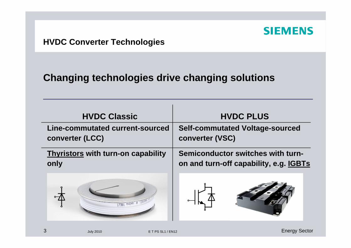
HVDC Converter Technologies
Semiconductor switches with turn-on and turn-off capability, e.g. IGBTs
Thyristors with turn-on capability only
Self-commutated Voltage-sourced converter (VSC)
Line-commutated current-sourced converter (LCC)
HVDC PLUSHVDC Classic
Changing technologies drive changing solutions
4 July 2010 Energy SectorE T PS SL1 / EN12
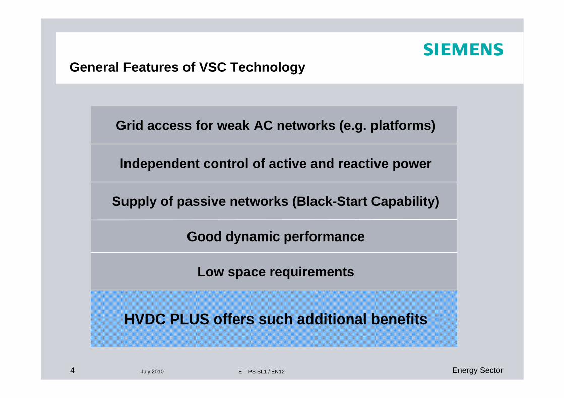
General Features of VSC Technology
Grid access for weak AC networks (e.g. platforms)
Good dynamic performance
Independent control of active and reactive power
Supply of passive networks (Black-Start Capability)
Low space requirements
HVDC PLUS offers such additional benefits

5 July 2010 Energy SectorE T PS SL1 / EN12
-1.00
-0.75
-0.50
-0.25
0.00
0.25
0.50
0.75
1.00
-1.25 -1.00 -0.75 -0.50 -0.25 0.00 0.25 0.50 0.75 1.00 1.25
P [p.u.]
Q [p
.u.]
HVDC PLUS (VSC - MMC)typical P/Q diagram
Rectifier Inverter
“over-excited”
“under-excited”
The reactive power can be controlled to any value within the limiting characteristics
Current Limit
Voltage Limit
Design Specification

6 July 2010 Energy SectorE T PS SL1 / EN12
VSC Technology – A look backTwo level converter
+Ud/2
-Ud/2
High level of harmonic distortionHigh steep front voltages resulting in HF noise and stress of component insulation
Desired voltageRealized voltage
α−
α−
α−
α−
α−
α−
α−
α− α− α− α− α−

7 July 2010 Energy SectorE T PS SL1 / EN12
Modular Multilevel Converter - MMC
Low level of harmonics and HF noise
Low switching losses
Modular arrangement with identical two-terminal power modules
Ud
Uac
+
+
+
+
+
+
+
+
+
+
+
+
+
+
+
+
+
+
+
+
+
+
+
+
+Ud/2
-Ud/2

8 July 2010 Energy SectorE T PS SL1 / EN12
Subjects of Presentation
HVDC Converter Basics
Windfarm Interconnector Solutions
HVDC PLUS – VSC MMC Application
HVDC PLUS – VSC MMC Design Details
Multiterminal HVDC (MTDC)

9 July 2010 Energy SectorE T PS SL1 / EN12
HVDC PLUS with MMC – Basic Scheme
PM 1
PM 2
PM n
PM 1
PM 2
PM n
PM 1
PM 2
PM n
PM 1
PM 2
PM n
PM 1
PM 2
PM n
PM 1
PM 2
PM n
ud
Phase Unit
Vd
IGBT2D2
D1IGBT1
Power Module (PM)
PowerElectronics
Converter Arm

10 July 2010 Energy SectorE T PS SL1 / EN12
Phase Unit
HVDC PLUS with MMC
Modular Multilevel Converter
PLUSCONTROL
Power Module

11 July 2010 Energy SectorE T PS SL1 / EN12
States of Power Modules
Energization Capacitor On Capacitor Off(converter blocked)
(charging) (charging)
(discharging)

12 July 2010 Energy SectorE T PS SL1 / EN12
MMC – perfect Voltage Generation
VConv.
- Vd /2
0
+Vd /2
AC and DC Voltages controlled by Converter Module Voltages:
VAC

13 July 2010 Energy SectorE T PS SL1 / EN12
Id
-Ud/2
+Ud/2
ControlIac /2
Iac /2Id /3
Iac
MMC – AC & DC Converter Currents ...
… controlled by Voltage Sources

14 July 2010 Energy SectorE T PS SL1 / EN12
=
~
=
=
~
=
=
~
=
n
2
1
1
2
n
Converter Reactors
Phase Unit
Parallel connection of three voltage sources
Damp balancing currents between different phases
Limit current gradient during severe faults

15 July 2010 Energy SectorE T PS SL1 / EN12
Subjects of Presentation
HVDC Converter Basics
Windfarm Interconnector Solutions
HVDC PLUS – VSC MMC Application
HVDC PLUS – VSC MMC Design Details
Multiterminal HVDC (MTDC)

16 July 2010 Energy SectorE T PS SL1 / EN12
=
~
=
=
~
=
=
~
=
n
2
1
1
2
n
Power Electronics Module - Redundancy
Phase Unit
PLUSCONTROL
Power Module
High-Speed Bypass Switch
Single Module Failure

17 July 2010 Energy SectorE T PS SL1 / EN12
Complete ConverterLine-to-Line DC Fault
ikM
+
+
+
+
+
+
+
+
+
+
+
+
AC Grid
L1P L2P L3P
L1N L2N L3N
ik
ik

18 July 2010 Energy SectorE T PS SL1 / EN12
=
~
=
=
~
=
=
~
=
n
2
1
1
2
n
Line-to-Line DC Fault
PLUSCONTROL
Power Module
Protective Thyristor Switch
Phase Unit

19 July 2010 Energy SectorE T PS SL1 / EN12
Power Module
Control:- IGBTs- Bypass Switch- Bypass Thyristor
Monitoring:- IGBT on-state voltage- Capacitor Voltage- Loss of Capacitance
All signal exchange between the Power Module and the Module Management System is via two optical fibers

20 July 2010 Energy SectorE T PS SL1 / EN12
PLUSCONTROL Main Tasks – Current Control & Module Management
Individual switching of Power Modules
Power Module Charge Balancing
1
2
n
SIMATIC TDCC&P System
Measuring System
Calculation of required Converter Arm voltages
Control of active and reactive power
Current & Voltage Balancing Control
Power Module Monitoring

21 July 2010 Energy SectorE T PS SL1 / EN12
Control and ProtectionSystem Hierarchy Win-TDC with PLUSCONTROL
PLUSCONTROL
MMS nMMS 1
SCADA Interface
C&P Level
Operator Level
Switchgear & Auxiliaries Voltages & Currents Converter – Power Modules
SCADA Interface
RCIRCI
I/O Unit I/O Unit
I/O Level Measuring System
Remote HMI Local HMI
CCS
SIMATIC TDC
Win-TDC
SIMATICWinCC
Current Control System
Module Management System

22 July 2010 Energy SectorE T PS SL1 / EN12
HVDC PLUS with MMC – Basic Scheme
PM 1
PM 2
PM n
PM 1
PM 2
PM n
PM 1
PM 2
PM n
PM 1
PM 2
PM n
PM 1
PM 2
PM n
PM 1
PM 2
PM n
ud
Phase Unit
Vd
IGBT2D2
D1IGBT1
Power Module (PM)
PowerElectronics
Converter Arm

23 July 2010 Energy SectorE T PS SL1 / EN12
Modular Design: Power Module
The Power Module- a two terminal component
Capacitor Unit
Power ElectronicsPower ElectronicsPower Electronics
series connected Power Modules

24 July 2010 Energy SectorE T PS SL1 / EN12
HVDC PLUS (VSC – MMC)converter tower arrangements

25 July 2010 Energy SectorE T PS SL1 / EN12
Parallel Water Cooling
It provides all IGBTs in the power modules with the same cooling water temperature Electrolytic currents are minimized by the use of grading electrodesCareful choice of materials allows operation without de-oxygenizing equipment None of these systems had corrosion problems
a Power Module / b Heat Sink / c Piping / d Manifold
The Siemens Design of the Valve-Cooling Circuit with Parallel-Water Coolinghas been in Operation for more than 30 Years with thyristors

26 July 2010 Energy SectorE T PS SL1 / EN12
HVDC PLUSdecreasing Converter Station Losses
HVDC PLUS Station Losses at Nominal Load
0.0%
0.5%
1.0%
1.5%
2.0%
2.5%
2006 2007 2008 2009 2010
R & D and System Engineering Progress
Loss
esin
%
30 M
W T
est F
acili
ty
Tran
s B
ay C
able
- Ambient Conditions & Cooling Concept
- Power Rating & Operation Specification
- Transformer & Aux. Power Concept

27 July 2010 Energy SectorE T PS SL1 / EN12
HVDC PLUSVSC - MMC topology - features and benefits
Low semiconductor switching frequency
Low generation of harmonics
High modularity in hardware and softwareUse of well-proven standard componentsSinus shaped AC voltage waveforms
Easy scalability
Reduced number of primary components
Low converter losses
No filters required
High flexibility, economical from low to high power ratings High availability of state-of-the-art components Use of standard AC transformers
Low engineering efforts
High reliability,low maintenance requirements

28 July 2010 Energy SectorE T PS SL1 / EN12
HVDC PLUS Monopolar Configuration – Overview
tertiary winding(optional)
conventional AC transformers
secondary breaker(optional)
star point reactor 2nd star point reactor(optional)
secondary breaker(optional)

29 July 2010 Energy SectorE T PS SL1 / EN12
HVDC PLUSincreasing in maximum power range

30 July 2010 Energy SectorE T PS SL1 / EN12
HVDC PLUS ApplicationLarge Interconnectors
Link 11000 MW
Link 21000 MW
Converter Stationsin a land cable system

31 July 2010 Energy SectorE T PS SL1 / EN12
Supply of HVDC PLUS converter transformer
31
Logistic challengeHeavy duty transports
Transformer tank of severalhundred tons= largest indivisible item
Transformer oil(non hazardous goods)
several hundred tons have to be on site at the same time, supplied in container tanks and small quantity in barrels
General cargo
Accessories have to be on siteat same time
EXAMPLE

32 July 2010 Energy SectorE T PS SL1 / EN12
photographs show challenging dimensions
HVDC PLUS in applicationChallenging Transformer Transports
Coordination isnecessary to designtransformer dimensionsmatching to clearancesof obstacles on roadtransport routes and suitable transportequipment
Railwaybridgeacrossroad

33 July 2010 Energy SectorE T PS SL1 / EN12
HVDC PLUS in applicationTransformer Transport Solution
Correlation of design solution with transport equipment
low clearance below the viaduct require transport of tansformer tank in a bridge of long side girders carried on two multi-axle trailers (as below)Route survey of transport specialists has to confirm their transport equip-ment is suitable and all maneuvers to pass the obstacle are possible

34 July 2010 Energy SectorE T PS SL1 / EN12
Subjects of Presentation
HVDC Converter Basics
Windfarm Interconnector Solutions
HVDC PLUS – VSC MMC Application
HVDC PLUS – VSC MMC Design Details
Multiterminal HVDC (MTDC)

35 July 2010 Energy SectorE T PS SL1 / EN12
HVDC PLUS for Grid AccessOffshore Windfarm project solutions
HVDC Link
OffshoreAC-System
OnshoreAC-Grid

36 July 2010 Energy SectorE T PS SL1 / EN12
HVDC PLUS ApplicationsConnection of remote Offshore Windfarms
Offshore Steady State Requirements- Blackstart and Power Reversal- Voltage and Frequency Control by Converter- Active Power determined by wind speed- Reactive Power control by Wind Farm within limits
Onshore & Offshore Faults- Reactive current injection from HVDC
AC Voltage Restoration / AC Protection
Onshore Faults- Concept for Fault-Ride-Through of Windfarm:
(i) Fast Telecom (ms) Windfarm Main Controller
(ii) Offshore Frequency Increase Overfrequency Detection in (ms)
(iii) “Mirroring“of Onshore Fault LVRT of Different Turbine TypesSC Current Contribution
(iv) Onshore Chopper Complete Isolation of Onshore Faults

37 July 2010 Energy SectorE T PS SL1 / EN12
HVDC PLUS ApplicationDC Transmission System with Onshore Chopper
Offshore Onshore
Multilevel Chopper Module
PM Electronics
+

38 July 2010 Energy SectorE T PS SL1 / EN12
HVDC PLUS and WIPOS: BorWin 2, Germany – World’s first VSC HVDC with 800 MW
38 E T PS SL/Re Power Transmission Division06-2010
2013
~ == ~ ==
~= =
~= =
Wind Farms: Veja Mate and Global Tech 1 – 800 MW,located 125 km Offshore (Northwest of the Island of Borkum)
The Siemens Wind Power Offshore Substation (WIPOS) is designed as a floating, self-lifting Platform
The Platform will be towed by Tugs to its Destination at Sea, where the Water is about 40 meters deep
A large heavy-duty Crane vessel is not needed to lift the Topside onto its Foundation
The Modular Multilevel VSCTechnology (MMC) reduces Complexity and therefore the Space required for Installation

39 July 2010 Energy SectorE T PS SL1 / EN12
Grid Access of Green Energy with HVDC PLUS:WIPOS – Advanced Offshore Platform Layout *
39 Power Transmission Division02-2010 E T PS SL/Re
Siemens Wind Power Offshore Substation (WIPOS) is designed as a floating, self-lifting *Platform
The Platform will be towed by Tugs to its Destination at Sea, where the Water is about 40 meters deep
A large heavy-duty Crane vessel is not needed to lift the Top-side onto its Foundation
The Modular Multilevel VSC Technology (MMC) reduces Complexity and therefore the Space required for Installation

40 July 2010 Energy SectorE T PS SL1 / EN12
HVDC PLUSContract for Borwin 2 Offshore HVDC
Overview OWP, Cable routes and Connection Points
Borwin 2Converter StationsPower 800MW @ +/-300kV DCone station on Offshore PlatformOffshore Wind Parks (OWP): Veja
Mate (Bard), Global Tech 1 (Wetfeet) each 400MW rated
DC-Cable 300 kV extruded:- 127 km Submarine Cable- 75 km Land CableAC-Cable 150kV: 39 km- OWP-ConnectionService Contract
Transpower Project
Diele / Börde
Büttel

41 July 2010 Energy SectorE T PS SL1 / EN12
Subjects of Presentation
HVDC Converter Basics
Windfarm Interconnector Solutions
HVDC PLUS – VSC MMC Application
HVDC PLUS – VSC MMC Design Details
Multiterminal HVDC (MTDC)

42 July 2010 Energy SectorE T PS SL1 / EN12
HVDC PLUS for Grid AccessOffshore Windfarm project solutions
A
100 km
100 km
300 km
C
B
400 MW
400 MW
400 MW
C
200 MW
200 MW
200 MW
MTDC in full scale:4 x +/-300 kV
Combined DC/AC:2 x +/-300 kV& AC Compensation
Converter Rating:

43 July 2010 Energy SectorE T PS SL1 / EN12
HVDC PLUS with MultiterminalsMTDC: Udc control concepts
1. Master-Slave Stations- Power is determined by
all but one station- Master station controls Udc
Reliability of Master determinesOverall System Performance
Converter Station 2
M
M
~
=
=
Converter Station 3
M
M
~
=
=
M
Converter Station 1
M
M
~
=
=
M
2. Identical Udc/P Droop Stations- Udc/P droop is analogous to
Power-Frequency Control in AC systems
Voltage Disturbance causes Primary Reaction: Power infeed according to Udc/P Droop
Secondary Control restores load flow

44 July 2010 Energy SectorE T PS SL1 / EN12
HVDC PLUS with MultiterminalsMTDC with DC Faults
HVDC PLUS Converter Fault Pattern:
1. Low impedance DC faults / Udc decreases sharply: Power Module capacitors clamped via D1No transient discharge events
2. Uncontrolled charging currents from AC Side:Fault current amplitude >10kA exceeds IGBT current rangeThyristor prevents thermal overload of D2
Required Fault Clearing Time in 50…100 ms RangeEasy Recovery of HVDC PLUS
Selective Fault Clearing DC Grids:
Concepts for:DC resonance breakers (existing HVDC classic)Semiconductor breakers (R&D)
PM Electronics
+D1
D2

45 July 2010 Energy SectorE T PS SL1 / EN12
Thank You!
Schutzvermerk / Copyright-VermerkPower Transmission and Distribution