technology failure of 1. introduction fastening screws and
TRANSCRIPT

278
Technology
Fastener World no.180/2020
Failure of Fastening Screws and Their Preventive MethodsExamples of practical application of CD bolts, 8th reportby Shin-ichi Nishida, Emeritus Prof. of Saga University
1. Introduction In the 6th report (the first half) and the 7th report (the last half), the author referred
to a new method for improvement of the fatigue strength of bolt. First of all, the factors related to the fatigue strength of bolt have been quantitatively evaluated by performing fatigue tests accounting on thread profile, root radius, pre-stressing and mechanical properties of bolt and nut, respectively. In addition, the author had pointed out for the first time in the world that the low fatigue strength of the bolt was attributable to the following four factors:
1. Uneven load sharing among the threads
2. Concentration of tensile stress
3. Concentration of bending stress, and
4. Localized loading.
The method being introduced in Fig. 7.1 is a new method for improving the fatigue strength of bolts in which the fatigue strength of the bolt is remarkably improved, regardless of whether a tightening force is applied to the bolt or not (see 7th report). That is, only the CD bolt had taken the preventive measures against the above four factors on the basis of theoretical mechanics at present. Therefore, the CD bolt shows the remarkably higher fatigue limit than the conventional ones by about two times and this bolt would also show excellent performance not only for delayed fracture but also stress corrosion crack (SCC).
This report will introduce some examples of practical application of CD bolts in engineering equipment.
2. Practical examples of CD bolts Table 8.1 lists some example of practical application of CD bolts. These are rather
large diameter bolts, which are used in jointed portions of the important parts for the machines and equipment.
Table 8.1 Representative examples of practical application about CD bolts
1. Tie rod of a rolling mill (φ475×13,975mm in length )2. Steel tower for power supply (flange joint of pipe)3. Elastic joint of rail for a rail road4. Fixed finger plate of a mono-rail (in Kitakyushu, Osaka and Naha cities)5. Fixed pallet wall of a sintering machine6. Fixed crane rail of an unloader 7. Jointed mast of a climbing crane
2.1 Tie rod of a rolling mill Figures 8.1 and 8.2 show an application of the CD bolt (φ475 in thread
diameter×13,975mm in length, 4 rods) to the tie rod of a rolling mill. Machining and shaping was performed in the specialized company for big and long screws in Osaka city. Especially, the thread portion of the bolt and nut was machined by the same portion of the same lathe. In addition, the shape of the thread was confirmed by pressing with silicon-rubber for its precise profile. The threaded portion of the rod was finished by CD shaping and applied with a gray colored MoS2 to avoid galling between the bolt and nut. The materials of the bolt and nut are SCM440 and cast iron, respectively. The Young modulus of the former is E=206GPa and that of the latter is E=100GPa, respectively. That is, the latter is about two times smaller than the former. As far as fastening screw, the internal force due to external varying force, becomes smaller due to small Young modulus and its bolt can endure still larger applied stress (see 5th report, Fig.5.11).
Figure 8.2 shows the lower (left) and upper (right) part of a rolling mill, respectively. These new tie rods with the CD shaping have been continuously operating for over a quarter of a century, while the conventional rods were broken from fatigue after only 3 years of operation (see 2nd report, Fig.2.2). The above result demonstrates the excellent fatigue properties of the CD bolt.
Fig. 8.1 Tie rod of a rolling mill (φ475×13,975mm in length)
Fig. 8.2 Lower (left) and upper part (right) of a rolling mill

280
Technology
Fastener World no.180/2020
This accident happened in Kakegawa station yard of JR Tokaidou Shinkansen. The failed bolt for fixing rail to its sleeper was shot to the wall of a private house far from the railway by about 80m and the wall was broken with a hole. In addition, the owner of the house found the broken bolt in the neighboring place when repairing his wall two days later. This bolt was used for fixing the rail to its sleeper and to be clear to coincide with the bolt. This bolt was considered to be broken by the wind pressure of Shinkansen train with high speed due to "fatigue".
Bolt: φ2.4cm×4.5cm in length (about 600gf)
(September 14th in 1993, Asahi morning news-paper)
2.2 Steel tower for power supply (flange joint of pipe) Figure 8.3 shows an outer appearance of conventional steel tower for power supply. This is made
by an equal angle with grey color, which is galvanized by hot dip coating with melted zinc. On the other hand, the recent steel tower for power supply is lately standing out for its height and colors. The steel tower is made of pipes with welded flange and fastened by the bolts. This is practically colored in distinguished red and white for its height. Figure 8.4 shows an outer appearance of a recent steel tower for power supply. The life of a conventional steel tower is about 50 years. On the other hand, the recent one is one hundred years and two times longer than the conventional one. As the steel tower shown in Fig. 8.4 is used between the channel and higher than the ordinary one, the CD bolts are adopted in the fastened portion by taking account of the cyclic load due to frequently violent wind (see Fig. 8.5). The weight of the CD bolts is about 3% of the total weight of steel pipes and that in all is 30tf.
2.3 Elastic joint for a rail road When the train, named “Nozomi”, running faster than the previous express train, called “Hikari”,
starts service, many troubles happened, such as several cracks in the body of the trains and falling of bolts from the trains. The above troubles will be considered to be the beginning failures during new operation. In addition, an M24 bolt, which was used for fixing rail on its sleeper, was broken due to fatigue and was directly shot to the wall of a private house about 80m away from the railway at the speed about 270km/h (see Table 8.2). The failed bolt is M24 being similar to the size of one’s fist (about φ40×42mm, 600gf in weight, in the case of double nuts). Taking account of the above accident, the importance of fatigue strength of the fastening bolts has been reviewed and concluded to the introduction of CD bolts for use on railways. Figures 8.6~8.8 show the tightening operation of CD bolts on site. In addition, Figure 8.9 shows the CD bolts used in the railway in JR Tokaido Shinkansen Track in Japan. Though more than 10 years have passed after these CD bolts were fastened, no troubles about the bolts have happened in these fields.
Fig. 8.3 Conventional steel tower for power supply with equal angle
Fig.8.4 Recent steel tower for power supply with pipe
Fig. 8.5 The CD bolt of steel tower for power supply across Oto-channel in Kyushu power company
Fig. 8.6 Elastic joint of rail road in JR Tokai
Fig. 8.7 Fastening operation with an impact wrench Fig. 8.8 Setup of the CD bolt with strain gauges Fig. 8.9 The CD bolts for fish plate in branching part of rail road
Fig. 8.11 Jointed part of monorail in Kitakyushu City (about 80 number of bolts/joint)
Fig. 8.10 Outer appearance of monorail in Kitakyushu City
Table 8.2 Bolt attacks a private house5)
2.4 Fixed finger plate of a mono-rail (in Kitakyushu, Osaka and Naha cities)
Figure 8.10 shows an appearance of the running train in Kitakyushu mono-rail. As understood from the above figure, the mono-rail train runs across or along the road with busy traffic density from a height of about 10m above the ground. The rail of concrete is elastically jointed with fixed finger plate using about 80 bolts each 10m distance. This fixed finger plate is settled at the connected portion between the rails of concrete at the center portion in Fig. 8.11. This system allows only the
282
Technology
Fastener World no.180/2020
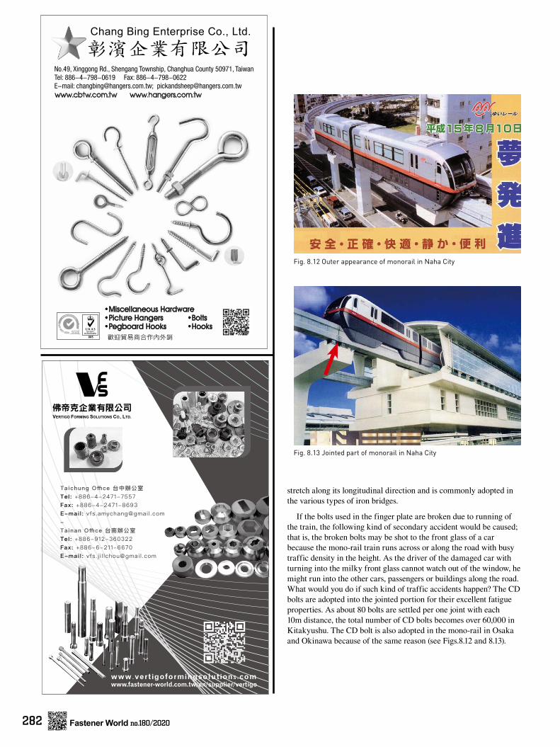
Fig. 8.12 Outer appearance of monorail in Naha City
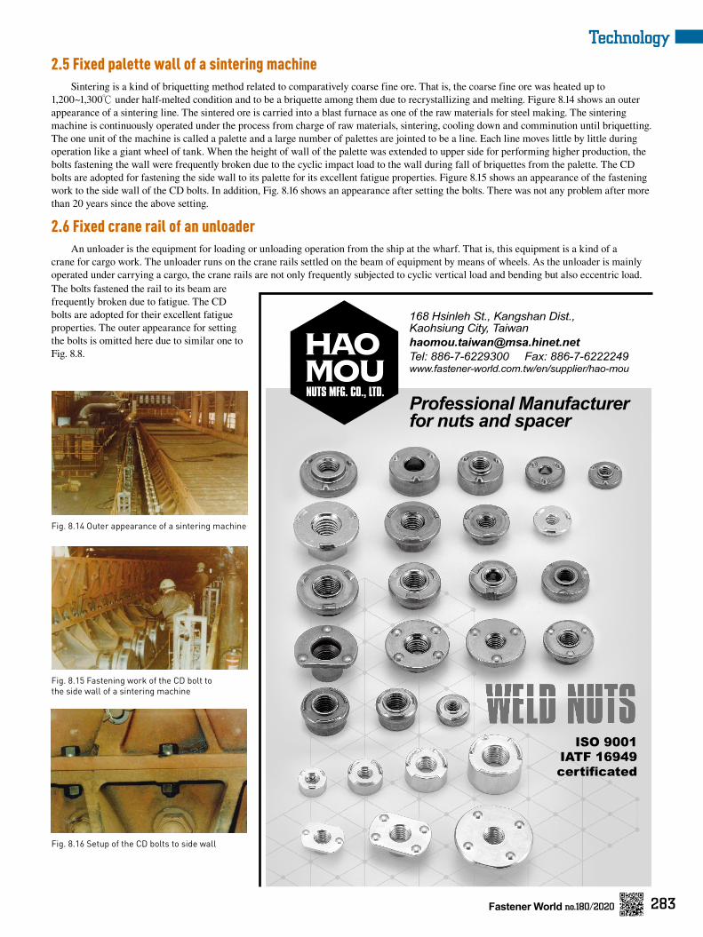
Fig. 8.13 Jointed part of monorail in Naha City
stretch along its longitudinal direction and is commonly adopted in the various types of iron bridges.
If the bolts used in the finger plate are broken due to running of the train, the following kind of secondary accident would be caused; that is, the broken bolts may be shot to the front glass of a car because the mono-rail train runs across or along the road with busy traffic density in the height. As the driver of the damaged car with turning into the milky front glass cannot watch out of the window, he might run into the other cars, passengers or buildings along the road. What would you do if such kind of traffic accidents happen? The CD bolts are adopted into the jointed portion for their excellent fatigue properties. As about 80 bolts are settled per one joint with each 10m distance, the total number of CD bolts becomes over 60,000 in Kitakyushu. The CD bolt is also adopted in the mono-rail in Osaka and Okinawa because of the same reason (see Figs.8.12 and 8.13).
283
Technology
Fastener World no.180/2020
Fig. 8.14 Outer appearance of a sintering machine
Fig. 8.15 Fastening work of the CD bolt to the side wall of a sintering machine
Fig. 8.16 Setup of the CD bolts to side wall
2.5 Fixed palette wall of a sintering machine Sintering is a kind of briquetting method related to comparatively coarse fine ore. That is, the coarse fine ore was heated up to
1,200~1,300℃ under half-melted condition and to be a briquette among them due to recrystallizing and melting. Figure 8.14 shows an outer appearance of a sintering line. The sintered ore is carried into a blast furnace as one of the raw materials for steel making. The sintering machine is continuously operated under the process from charge of raw materials, sintering, cooling down and comminution until briquetting. The one unit of the machine is called a palette and a large number of palettes are jointed to be a line. Each line moves little by little during operation like a giant wheel of tank. When the height of wall of the palette was extended to upper side for performing higher production, the bolts fastening the wall were frequently broken due to the cyclic impact load to the wall during fall of briquettes from the palette. The CD bolts are adopted for fastening the side wall to its palette for its excellent fatigue properties. Figure 8.15 shows an appearance of the fastening work to the side wall of the CD bolts. In addition, Fig. 8.16 shows an appearance after setting the bolts. There was not any problem after more than 20 years since the above setting.
2.6 Fixed crane rail of an unloader An unloader is the equipment for loading or unloading operation from the ship at the wharf. That is, this equipment is a kind of a
crane for cargo work. The unloader runs on the crane rails settled on the beam of equipment by means of wheels. As the unloader is mainly operated under carrying a cargo, the crane rails are not only frequently subjected to cyclic vertical load and bending but also eccentric load. The bolts fastened the rail to its beam are frequently broken due to fatigue. The CD bolts are adopted for their excellent fatigue properties. The outer appearance for setting the bolts is omitted here due to similar one to Fig. 8.8.

284
Technology
Fastener World no.180/2020
2.7 Jointed mast of a climbing crane The climbing crane is used on construction sites. For instance, the crane is set on the
top of the building under construction and operated for carrying the building materials or assemblage of the parts, etc. This crane can be separated into several pieces after completion of the building and carried into the next construction site. The climbing crane is normally hoisted up and down under its own power along the main pillar called the mast. The height of the mast can be adjusted according to the condition of the construction site and a large number of bolts are used in the main pillar. Figure 8.17 shows an outer appearance of the mast of climbing crane. Though the fatigue failure of the bolts is occasionally reported in the past due to suffering varying stress, such kind of failure does not appear after the adoption of CD bolts. Figures 8.18 and 8.19 show the CD bolts settled to the jointed portion of the climbing crane and the same type of the CD bolt as the above, respectively.
3. The merits for users The users can get the following merits by using the CD bolts for jointed portions which
suffer cyclic load.
1. Safer and higher reliable fastening joints.
2. Cost reduction due to introduction of less number of bolts or smaller size bolts.
3. Maintenance free for jointed portions due to the above reasons, etc.
4. Conclusions As the CD bolt shows its excellent fatigue properties, this bolt can be expected to be
applied to the jointed portions of many kinds of machines and equipment (see Table 8.3).
1. The representative examples of practical application of the CD bolt are listed in the following; ① Tie rod of a rolling mill, ② Steel tower for power supply (flange joint pipe), ③ Elastic joint for rail road, ④ Fixed finger plate of a mono-rail, ⑤
Fixed pallet wall of a sintering machine, ⑥ Fixed crane rail of an unloader, ⑦
Jointed mast of a climbing crane, etc.
2. There is no problem in the above machines and equipment where the CD bolt was used on the jointed portion.
3. The users can get the following merits by using the CD bolts for jointed portions. ① Safer and higher reliable fastening joints, ② Cost reduction due to introduction of less number of bolts or smaller size bolts, ③ Maintenance free for jointed portions due to the above reasons, etc.
Fig. 8.17 Outer appearance of climbing crane
Fig.8.18 Setup of the CD bolts to the mast of a climbing crane
Fig. 8.19 The CD bolt for a climbing crane(M52×235∼250mm in length)
Table 8.3 Result of practical application of the CD bolts
References: (1) S. Nishida, Failure Analysis of Machine Parts & Equipment, (1993), pp.85 and 122, Nikkan Kogyo News Paper Co. Ltd, (in Japanese)
(2) S. Nishida, Failure Analysis in Engineering Applications, (1993), pp.71 and 103, Butterworth Heinemann Co. Ltd. UK
(3) S. Nishida, Failure Analysis of Machines & Components, (1995), pp.85 and 122, Kinkado Co. Ltd, (in Japanese)
(4) S. Nishida, C. Urashima, H. Tamasaki, A New Method for Fatigue Life Improvement of Screw, Fatigue Design Components, ESIS Publication 22, (1998), pp.215, Elsevier Science Ltd.
(5) For example, Asahi morning newspaper, (September 14th, in 1993), Asahi News Paper Co. Ltd.
Summary:
1. As far as the application of the CD bolt, remarkable effect can be especially observed in large size bolts and seriously failed portions, though there is no limitation.
2. There are no problems about the past application of CD bolts.
3. The CD bolt is hard to be broken in loosened condition, though anti-loosening measure is not considered.
4. The merits for the user; reliable bolt joints, light weight or reduction of cost by decrease of number of bolts or its decrease of diameter and anti-stress corrosion cracking and anti-delayed fracture.