technology leap in dc current measurement opens new ... · technology leap in dc current...
TRANSCRIPT

Technology leap in DC current measurement opens new opportunities for aluminium smelters
Reprint from Aluminium 2005/1-2

Within the electro-chemical in-dustry, dc current measurementsystems are required and well-established for process controland regulation. Conventionalhigh dc current transducers uti-lize the Hall effect to measure themagnetic field around the currentcarrying bus bars. Over the yearsHall effect transducers have be-come very accurate and reliable.However, they are rather complexsystems and demand intricate in-stallation and commissioningprocedures. Special care must betaken to avoid erroneous outputdue to asymmetric field distribu-tions and to disturbances fromneighbour currents or busbar cor-ners. ABB’s newly developedFiber-Optic Current Sensor(FOCS) is a spin-off from a sen-sor developed for high-voltagesubstations and it opens totallynew opportunities in the field ofhigh current dc measurement.
Conventional Hall effect current transducers
A Hall effect dc current transducer(figs. 1 and 2) has a magnetic coresurrounding the current-carryingbus bars. A number of Hall ele-ments are positioned in gaps alongthe core and detect the magneticflux. In the most accurate models,the signals of the Hall elements arefed to high gain current amplifi-ers. These amplified currents passthrough solenoids around the coreand generate a magnetic fieldcompensating the field of the pri-mary current. The sum of the so-lenoid currents is proportional tothe primary current. Simpler typesof Hall current transducers, com-monly with lower accuracy, workwithout closed-loop flux compen-sation and translate the Hall cur-rents directly into an output sig-nal.
Hall effect dc current transdu-
cers with closed-loop magneticflux nullification, though veryprecise, are rather complexsystems, with weights up to 2 000kg. Furthermore, in the case of an-gled bus bar arrangements, ananalysis of the magnetic field dis-tribution is often necessary in or-der to place the transducer head insuch a way as to minimise errorsdue to asymmetric fields, or cross-
talk from neighbour currents. Forexample, erroneous output mayresult from inhomogeneous heatdissipation in the transducer, orfrom amplifier saturation at localfield maxima, or from a local re-versal in the field direction causedby neighbour currents. These areonly a few of the aspects wherefiber-optic current sensors offerclear advantages.
Technology leap in DC current measurement opensnew opportunities for aluminium smeltersM. Wiestner, M. Wendler and K. Bohnert, Baden
Fig. 1: Hall effectdc current trans-ducer with mag-netic flux nullifi-cation (principle)
Fig. 2: Hall effect dc current transformers LEM LKP 400

Fiber-Optic Current Sensor(FOCS)
In the fiber-optic current sensor asimple loop of optical fiber aroundthe bus bar replaces the sophisti-cated head of the conventionaltransducer. The sensor perfectlyintegrates the magnetic field alongthe closed path described by thesensing fiber. As a result, the sig-nal is independent of the detailedform of magnetic field distributionand is only determined by the en-closed current. All currents out-side the fiber loop are of no influ-ence. Sensor placement is there-fore uncritical. The simplicity ofthe system reduces to a few hoursthe time required for installationand commissioning.
The sensor makes use of the Far-aday effect in the fiber. The Fara-day effect is the phenomenon thatin a medium such as glass rightand left circularly polarized lightwaves travel at different speeds ifa magnetic field is applied alongthe propagation direction (fig. 3).As a result the waves accumulatea path difference δL or equivalent-ly a phase difference δΦF = 2 V LH. Here, V is a material constant(Verdet constant), L the length ofthe rod, and H the magnetic field.Fig. 4 schematically illustrates theset-up of ABB’s fiber-optic currentsensor. Two light waves with or-thogonal linear polarizations trav-el from the optoelectronics mod-ule, which includes a semiconduc-tor light source, via an intercon-necting fiber to the single-endedsensing fiber. The sensing fiberforms an integral number of loops,N, around the bus bar. A singleloop is commonly sufficient forhigh dc currents. At the entranceof the sensing fiber a fiber-opticphase retarder converts the or-thogonal linear waves into left andright circularly polarized light.The circular waves travel throughthe coil of sensing fiber, are re-flected at the end of the fiber andthen retrace their optical path backto the coil entrance. Here, they areagain converted into orthogonallinearly polarized waves. Due tothe reflection the polarization di-rections of the returning waves are
swapped with respect to the initialforward propagating waves. Sincethe two circularly polarised wavestravel at slightly different speedsthrough the sensing fiber if a dccurrent, I, is flowing, the two re-turning light waves accumulate aphase difference given by ∆ΦF= 4V N I. The phase difference is pro-portional to the line integral of themagnetic field along the sensingfiber and is therefore a directmeasure for the current. The re-turning waves are brought tointerference in the optoelectronicsmodule. The signal processor thenconverts the optical phase differ-ence into a digital signal. Besidesthe simplicity of the arrangement,a particular advantage of opera-ting the sensing coil in reflectionis the fact that the sensor signal islargely immune to mechanicalperturbations such as shock andvibration. While the non-reciprocal Faraday optical phaseshifts double on the ways forwardand backward, phase shifts causedby mechanical disturbances arereciprocal and cancel each other.
The technology of the optoelec-tronic detection circuit is the sameas is used in fiber gyroscopes andit has been well proven in de-manding navigation systems. Fi-
ber gyroscopes use the Sagnac ef-fect seen by two counter-propagating light waves in a fibercoil to measure rotation velocities.
ABB FOCS system design and interfaces
The sensing fiber is packaged inproprietary sensing strip, whichallows perfectly closing the fiberloop in a straightforward manner.The sensing strip also prevents anyuncontrolled mechanical stress onthe sensing fiber. This is importantin order to maintain high accura-cy and stability. On-site recalibra-tion after installation of the sen-sor is not necessary. The sensingstrip resides in a modular andlightweight housing consisting ofsegments of fiber re-enforced ep-oxy (fig. 5). The sensor head canbe installed without opening thebus bars. By varying the lengths ofthe straight segments the head canbe easily adapted to different busbar cross-sections. The sensorhead is connected to the optoelec-tronics module via a robust fibercable.
The optoelectronics module ofthe sensor is integrated into ABB’sAC 800PEC Power Electronics
Fig. 3: Faraday effect
Fig. 4: Fiber-optic current sensor
Controller (fig. 4). The sensor isavailable as part of the ABB highpower converter systems as well asa stand-alone device. Build-inself-test features monitor thefunctional integrity of the control-ler and the sensor. Three different
output signal formats are avail-able: a digital output with 24 bitresolution via ABB’s high-speedoptical PowerLink protocol, viathe Profibus DP Slave fieldbusprotocol as well as analog currentand voltage outputs (0 (4) -20 mAand 0 (0.2) -1 V). Additionally, thethree following independentchange-over contacts are provid-ed to allow for monitoring andsignalization.
� Instantaneous DC Over Cur-rent Trip or inverse CurrentTrip (fig. 7),
� Instantaneous Reverse CurrentTrip,
� General Alarm in case ofover-temperature or other fail-ures.
FOCS performance and specifications
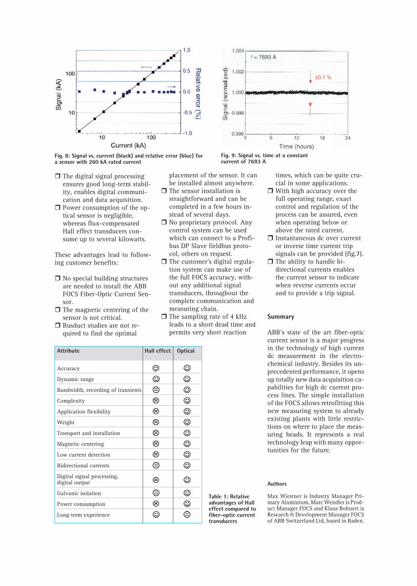
The sensor is available for ratedcurrents up to 500 kA with corre-sponding sensor head sizes. Thecurrent measuring range coversseveral orders of magnitude withvery good accuracy, also far belowthe specified nominal current. Theaccuracy is within ±0.1% from 1%to 120% of the nominal current.The temperature range of opera-tion is -40°C to 80°C for the sen-sor head and –25°C to 65°C for theelectronics (0°C to 65°C with aProfibus module). The data sam-pling rate is 4 kHz and allows re-covery of ac current componentsup to 2 kHz. Fig. 8 shows the sig-nal vs current relationship for a
sensor with a rated current of 260kA over a range from 3 kA to 300kA (black squares). The deviationof the signal from linearity (bluesquares) is well below 0.1%. Fig. 9shows the signal at constant cur-rent (about 7.7 kA) over a 24 h pe-riod. The signal stability is againwell within 0.1%.
Comparison of Hall effect and fiber-optic DC current transducers
Hall effect and optical currenttransducers are both highly accu-rate. However, the optical sensoroffers a number of important ad-vantages (see also table 1):
� The high accuracy of the opti-cal sensor is maintained overa very wide operating range ofcurrents.
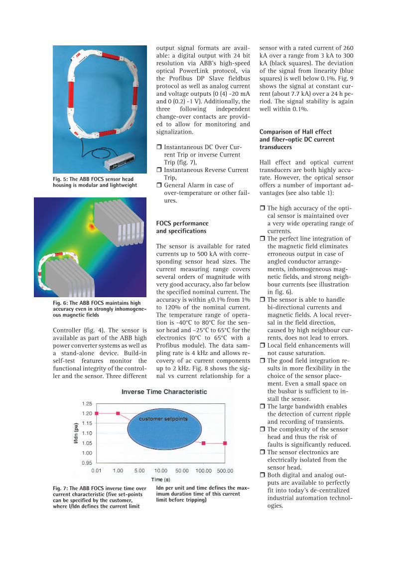
� The perfect line integration ofthe magnetic field eliminateserroneous output in case ofangled conductor arrange-ments, inhomogeneous mag-netic fields, and strong neigh-bour currents (see illustrationin fig. 6).
� The sensor is able to handlebi-directional currents andmagnetic fields. A local rever-sal in the field direction,caused by high neighbour cur-rents, does not lead to errors.
� Local field enhancements willnot cause saturation.
� The good field integration re-sults in more flexibility in thechoice of the sensor place-ment. Even a small space onthe busbar is sufficient to in-stall the sensor.
� The large bandwidth enablesthe detection of current rippleand recording of transients.
� The complexity of the sensorhead and thus the risk offaults is significantly reduced.
� The sensor electronics areelectrically isolated from thesensor head.
� Both digital and analog out-puts are available to perfectlyfit into today’s de-centralizedindustrial automation technol-ogies.
Fig. 5: The ABB FOCS sensor headhousing is modular and lightweight
Fig. 6: The ABB FOCS maintains highaccuracy even in strongly inhomogene-ous magnetic fields
Fig. 7: The ABB FOCS inverse time overcurrent characteristic (five set-pointscan be specified by the customer,where I/Idn defines the current limit
Idn per unit and time defines the max-imum duration time of this currentlimit before tripping)
Attribute Hall effect Optical
Accuracy
Dynamic range
Bandwidth, recording of transients
Complexity
Application flexibility
Weight
Transport and installation
Magnetic centering
Low current detection
Bidirectional currents
Digital signal processing,digital output
Galvanic isolation
Power consumption
Long term experience
� The digital signal processingensures good long-term stabil-ity, enables digital communi-cation and data acquisition.
� Power consumption of the op-tical sensor is negligible,whereas flux-compensatedHall effect transducers con-sume up to several kilowatts.
These advantages lead to follow-ing customer benefits:
� No special building structuresare needed to install the ABBFOCS Fiber-Optic Current Sen-sor.
� The magnetic centering of thesensor is not critical.
� Busduct studies are not re-quired to find the optimal
placement of the sensor. It canbe installed almost anywhere.
� The sensor installation isstraightforward and can becompleted in a few hours in-stead of several days.
� No proprietary protocol. Anycontrol system can be usedwhich can connect to a Profi-bus DP Slave fieldbus proto-col, others on request.
� The customer’s digital regula-tion system can make use ofthe full FOCS accuracy, with-out any additional signaltransducers, throughout thecomplete communication andmeasuring chain.
� The sampling rate of 4 kHzleads to a short dead time andpermits very short reaction
times, which can be quite cru-cial in some applications.
� With high accuracy over thefull operating range, exactcontrol and regulation of theprocess can be assured, evenwhen operating below orabove the rated current.
� Instantaneous dc over currentor inverse time current tripsignals can be provided (fig.7).
� The ability to handle bi-directional currents enablesthe current sensor to indicatewhen reverse currents occurand to provide a trip signal.
Summary
ABB’s state of the art fiber-opticcurrent sensor is a major progressin the technology of high currentdc measurement in the electro-chemical industry. Besides its un-precedented performance, it opensup totally new data acquisition ca-pabilities for high dc current pro-cess lines. The simple installationof the FOCS allows retrofitting thisnew measuring system to alreadyexisting plants with little restric-tions on where to place the meas-uring heads. It represents a realtechnology leap with many oppor-tunities for the future.
Authors
Max Wiestner is Industry Manager Pri-mary Aluminium, Marc Wendler is Prod-uct Manager FOCS and Klaus Bohnert isResearch & Development Manager FOCSof ABB Switzerland Ltd, based in Baden.
Fig. 8: Signal vs. current (black) and relative error (blue) fora sensor with 260 kA rated current
Fig. 9: Signal vs. time at a constant current of 7693 A
Table 1: Relativeadvantages of Halleffect compared tofiber-optic currenttransducers

ABB Switzerland LtdFiber-Optic Current SensorsDept. ATPR/FOCSCH-5300 Turgi / Switzerland
Web www.abb.com/powerelectronicsEmail [email protected]: +41 - 58 - 589 39 39Fax: +41 - 58 - 589 30 00 3B
HS
209
777
E01
_RE
V-
ABB Switzerland LtdAluminium Industry HeadquarterSegelhof5401 Baden-Dättwil / Switzerland
Web www.abb.com/aluminiumEmail [email protected]: +41 - 58 - 586 84 44Fax: +41 - 58 - 586 73 33