technology of free energy multiplier - borderlands.de · 1 technology of free energy multiplier...
TRANSCRIPT

1
Technology of Free Energy Multiplier edited by A. Schneider, Jan. 14, 2018
Updated, Jan. 15, 2018 Updated, Jan. 20, 2018 Updated, Jan. 22, 2018 Updated Febr. 17, 2018 Updated Febr. 19, 2018 Updated Nov. 17, 2018
It seems that the first who had the idea to pick up energy from the surroundings resp. from
the universally available «ether» was Nikola Tesla. As I summurized in the slides at the end
of this paper he refered in several of his interviews, publications and patents that such a
cosmic energy source really exists.
Several other inventors resp. « Tesla followers » have tried and sometimes succeeded to
build systems including a storage device like a battery which allows to produce continually
electrical energy.
There exist also theoretical papers to the possibility to convert energy from the vacuum
field like that of Tom Bearden, Lawrence Tesung, Prof. Claus Turtur et.al.
Links to practical implementations :
0. Carlos F. Benitez http://www.borderlands.de/Links/GB121561A.pdf
The inventor, a civil engineer of Guadalajar, Mexico, invented a method to produce electri-
cal energy by charging and discharging batteries alternatively. The discharging battery is
connected to a load and delivers a part of the energy to an oscillatory circuit provided with
a rectifier which sends the high frequency pulses through the second battery from the posi-
tive to the negative pole. It was found that this second battery can be charged in this man-
ner complety in the time lapse of time in wich the first battery discharges. Therefore it is
only a question of reversion the connections of said batteries from time to time and to
repeat the prodecure. A method to realize this switching is described In GB121,561 which
was completely accepted on Dec 24, 1918. In his base patent application 14,311, see :
http://potentialtec.com/GB191514311A.pdf , it is claimed :

2
The basic circuit as printed in the patent application No 14,311 (GB) is reproduced here :

3
https://www.youtube.com/watch?time_continue=12&v=q1FyajzU3So 8 :17 (2.11 :58)
Rick Friedrich explains in
this video how the inven-
tion of Carlos F. Benitez
really worked. Two serially
connected batteries 1+2
with together 24 V are fed
via some loads to two pa-
rallely connected batteries
3+4 (12 V) which are char-
ged at the same time by
the flowing current. After
some time the charging
and loading batteries are
interchanged so that bat-
tery 3+4 are serially con-
nected and batteries 1+2
are parallely connected.
And the current is flowing
now from battery 3+4 (24 V) via the load to battery 1+2 (12 V). Important is the oscillatory
circuit (below) which allows a faster and more effective charging of the batteries.
Originally Carlos F. Benitez used capacitors instead of batteries, see at time 34 :50 in the link
given above.
Also in this configuration the inventor emphasizes the need of an oscillatory circuit compo-
sed by a condensor, coils and a breaker. Evidently in this way it is possible to use resonance
energy for recharging the parallelly connected right batteries from the serially connected
two left batteries completely and to use some remaining additonal energy for external
loads (lamps connected to line 36, see on the right). This load is transformed via transfor-
mer windings to left part (noted with 5) as a serial load to the left condenser.
Much more can be learned by consulting the different videos of Rich Friedrich which can
be seen on the link mentioned above.
4
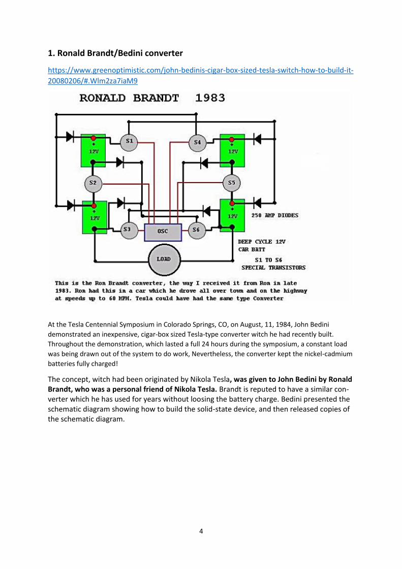
1. Ronald Brandt/Bedini converter
https://www.greenoptimistic.com/john-bedinis-cigar-box-sized-tesla-switch-how-to-build-it-
20080206/#.Wlm2za7iaM9
At the Tesla Centennial Symposium in Colorado Springs, CO, on August, 11, 1984, John Bedini
demonstrated an inexpensive, cigar-box sized Tesla-type converter witch he had recently built.
Throughout the demonstration, which lasted a full 24 hours during the symposium, a constant load
was being drawn out of the system to do work, Nevertheless, the converter kept the nickel-cadmium
batteries fully charged!
The concept, witch had been originated by Nikola Tesla, was given to John Bedini by Ronald Brandt, who was a personal friend of Nikola Tesla. Brandt is reputed to have a similar con-verter which he has used for years without loosing the battery charge. Bedini presented the schematic diagram showing how to build the solid-state device, and then released copies of the schematic diagram.

5
https://www.greenoptimistic.com/build-tesla-4-battery-switch#.Wlm3_a7iaM9
Tesla used the fact that lead ions are heavier than electrons. Every circuit, in it transitory phase (from zero-volt to x volts) develops a much higher voltage applied on the negative side. This voltage (pile-up of electrons meeting the much heavier lead ions) is then normally distributed in the circuit. If you cut off the load and the source battery, all the voltage made by the electrons gathered at the negative side of the battery you want to charge, go in that battery. If you do that from 200 to 800 times per second, you can charge the
destination battery (lead-acid) in a very short time (tens of minutes). By switching the batteries between them, you restart the process and reload the source battery.
Remark : According to Rick Friedrich it was found that such fast switching stresses the plates in the batteries to much which can result in batteries breack down.
There is a company (Electrodyne Corporation) who tested this ensemblement and for three years they fueled many devices, with no unusual damage to the batteries. According to the link : http://www.free-energy-info.co.uk/Chapt6.html Here you can read:
…The Electrodyne Corp. staff who experimented extensively with the Tesla Switch circuitry, found that when a battery was fully conditioned to used cold electricity, that a battery could be disconnected, discharged independently to it’s full capacity, and then re-charged completely in under one minute.
That style of operation completely overcomes the objections to using battery banks to power household equipment of any power…. This phenomenon is explained in more detail at the link: http://www.free-energy-info.com/Batteries.pdf

6
THIS HAS THE SAME EFFECT AS IF A MUCH HIGHER VOLTAGE SOURCE HAD BEEN CONNECTED TO THE BATTERY, CAUSING A MUCH GREATER RATE OF CHARGING. EFFECT ONLY LASTS FOR A FRACTION OF A SE-COND, AND IF YOU ARE USING A DC CHARGING SOURCE, IT ONLY OCCURS ONCE DURING THE CHARGING SESSION. However, IF WE CHOOSE, WE CAN ARRANGE OUR CHARGING CIRCUIT TO DO THIS SWITCH-ON STYLE OF CHARGING THOUSANDS OF TIMES EACH SECOND. FOR EXAMPLE, LAWRENCE TSEUNG PRODUCED A CHARGING SYSTEM WHICH IS A MODIFIED JOULE THIEF CIRCUIT AND HE STATES THAT IT IS
TEN TIMES MORE EFFECTIVE THAN OR-DINARY CHARGING,
see : http://www.free-energy-info.com/FLEET.pdf THE CIRCUIT IS CALLED THE F.L.E.E.T. DEVICE WHERE F.L.E.E.T. STANDS FOR THE “FOREVER LEAD-OUT EXISTING ENERGY TRANSFORMER” EMPHASISING THAT THE EXTRA ENERGY HAS NOT BEEN CREATED BUT INSTEAD HAS JUST BEEN DRAWN INTO THE CIRCUIT FROM THE ENVIRONMENT WHERE IT ALREADY EXISTED.
WHILE THE OUTER WINDING IS SHOWN HERE WITH THICKER WIRE OF A DIFFERENT COLOUR, THIS IS ONLY TO MAKE THE DRAWING EASIER TO UNDERSTAND. IN REALITY, THE OUTER WINDING IS MADE WITH EXACTLY THE SAME WIRE AS THE INNER WINDING. BOTH WINDINGS GO ALL OF THE WAY AROUND THE TOROID. TOTAL AMOUNT OF WIRE NEEDED TO MAKE THE WINDINGS IS ABOUT 70 METRES AND SO IT IS NORMAL TO BUY A 100-METRE REEL OF THE TWIN-CORE WIRE AS THAT IS ENOUGH TO MAKE BOTH WINDINGS AND STILL HAVE SOME OVER FOR OTHER THINGS.

7
TECHNICALLY MINDED PEOPLE, THE OUTPUT WAVEFORM LOOKS LIKE THIS : AND THERE ARE ABOUT 290,000 OF THOSE PULSES PER SECOND. AT AN EARLY STAGE, I DECIDED TO CONFIRM THAT FREE ENERGY EXISTED, AND SO I BUILT A FLEET CIRCUIT IN AN EVENING. I DECIDED TO USE TWO SMALL 12-VOLT LEAD-ACID BATTERIES FOR THE TEST AND I CHOSE TO USE FOUR DIODES IN A BRIDGE RATHER THAN JUST A SINGLE DIODE.
I CHOSE TO USE TWO BATTERIES AND STAY AWAY FROM ANY FORM OF MAINS INPUT SO THAT IT WOULD BE VERY CLEAR THAT NO CONVENTIONAL FORM OF ADDITIONAL POWER COULD UPSET THE RESULTS.
SO, I USED FLEET CIRCUIT POWERED BY ONE BATTERY TO CHARGE THE THE SECOND BAT-TERY. THEN I SWAPPED THE BATTERIES OVER AND USED THE SECOND BATTERY TO CHARGE THE FIRST. I DID THIS A COUPLE OF TIMES AND LET THE BATTERIES REST SO AS TO GET A RELIABLE READING FROM THEM. THE RESULT WAS A GENUINE GAIN OF REAL, USABLE POWER IN BOTH BATTERIES.
I CONSIDERED THAT RESULT TO SHOW THAT FREE-ENERGY IS MOST DEFINITELY A FACT, ES-PECIALLY SINCE LEAD-ACID BATTERIES WASTE 50% OF ALL OF THE POWER THAT YOU FEED INTO THEM WHEN CHARGING THEM, SO MY TEST HAD A CIRCUIT PERFORMANCE GREATER THAN COP=2.
THE EFFICIENCY OF THAT TEST WOULD PROBABLY HAVE BEEN VERY MUCH HIGHER IF I HAD CHARGED TWO OR MORE BATTERIES CONNECTED IN SERIES. THE COIL USED WAS WOUND ON A PLASTIC PIPE OFFCUT WHICH WAS TO HAND AT THE TIME. IT WAS 8 INCHES IN DIAMETER (200mm) AND 10mm X 12mm IN CROSS-SECTION AND THE WIRE WAS SINGLESTRAND 6-AMP CAPACITY EQUIPMENT WIRE WHICH WAS AVAILABLE AT THE TIME.

8
2. Tesla 4-battery system, Bedini 3-battery system, Ron Cole’s 1-battery system
http://www.vems.hu/freeenergy/pajert62/Tesla_Battery_Switch_2.PGFED.pdf
The current flowing through the bulb can be arranged to be a charging current for another
battery. It can both light the bulb and charge another battery without needing any extra
current: Here, the circuit is powered by battery 1 as before, but this time the current goes on
to charge battery 2.
Yes, battery 1 gets
discharged just as
before, but the plus
side is that battery 2
is getting charged up
all the time. The final
step is to swap the
batteries over:
And now, the newly
charged battery 2
lights the bulb and
charges up battery 1
again. Seem impos-
sible? Well it isn’t.
Nikola Tesla demonstrates this with his “4-battery switch” system where he chooses to
use four identical batteries to implement this circuit:
With 12-volt batteries as
shown here, the bulb has
the same 12 volts across
it as it would have had
with the single battery
shown in the first dia-
gram, as batteries 1 and
2 are wired “in series”
to give 24 volts, while
batteries 3 and 4 are
wired “in parallel” to
give 12 volts.
Nikola Tesla arranged his circuit to swap the batteries over with 1 and 2 taking the place of 3
and 4. He chose to do it in a slightly different way and he swapped the batteries over hund-
reds of times per second.
9
The Weird stuff:
There is another important factor involved in battery-charging circuits to be used with normal lead-acid batteries and that is the practical detail of the materials involved.
The charging process in this switching circuit is carried out by electrons flowing down the connecting wire and into the battery. The electrons flowing along the outer surface of the wire, move very rapidly indeed.
The main current inside the battery is carried by the charged ions inside the lead plates inside the battery. These ions are hundreds of thousands of times heavier than the electrons. This doesn’t matter at all once the ions get moving, but in the initial split second before the ions get going, the incoming electrons pile up like in a traffic jam tail-back.
This pile-up of electrons pushes up the voltage on the terminal of the battery, well above the nominal battery voltage, and so the charging starts off with a high-voltage, high-current pulse into the battery.
This is not normally noticed when using a standard mains-powered battery charger, as switch-on only occurs once during the whole charging process.
In the Tesla switch shown here, and in the Bedini circuits shown earlier, this is not the case. The circuit takes advantage of this difference in momentum between the electrons and the lead ions, and uses it repeatedly to great advantage.
The technique is to use very short duration pulses all the time. If the pulses are short enough, the voltage and current drive into the receiving battery is far greater than a quick glance at the circuit would suggest. This is not magic, just common-sense characteristics of the materials being used in this circuit.
A person unfamiliar with these systems, seeing John Bedini’s many advanced circuits for the first time, might get the impression that they are just crude, roughly-built circuits. Nothing could be further from the truth. John often uses mechanical switching because it gives very sharp switch-on and switch-off times. John is a complete master of this circuitry and knows exactly what he is doing.
The Electrodyne Corporation tested the Tesla 4-battery circuit over a period of three years.
They found that at the end of that period, the batteries did not show any unusual deterioration. The batteries used were ordinary lead acid batteries.
The system operated lights, heaters, television sets, small motors and a 30-horsepower electric motor.
If the batteries were run down to a low level and then the circuit switch on with a load, the rechar-ging of the batteries took place in under one minute.

10
No heating was experienced during this rapid charging. Heat was only produced during discharge cycles. If left undisturbed, each battery would charge up to nearly 36 volts. Control circuitry was developed to prevent this over-charging.
They used mechanical switching and stated that below 100 Hz there was not much advantage with the circuit and above 800 Hz it could be dangerous.
They didn’t mention why they consider that higher rates of switching could be dangerous. If we consider what exactly is happening, perhaps we can work out why they said that. The charging situation is like this
At Time “A” the switch closes, connecting a voltage source (battery, charged capacitor, or whatever) to a lead-acid battery. Electrons start flowing down the outside of the connecting wire.
Being very light and having little obstruction, they move very fast indeed (the electrons inside the wire only move a few inches per hour as getting through the wire is difficult).
All goes well until Time “B” when the leading electrons reach the lead plates inside the battery. Here, they have a problem, because the current flow through the plates is carried by lead ions.
Lead ions are very good at carrying current, but it takes them a split second to get going due to their
weight. That split second is critical and it opens the door to free-energy.
In that split second, the electrons pile up because they are still arriving down the wire at very high speed. So, at Time “C” they have built up into a large body of electrons.
This large body of electrons has the same effect as if there had been a sudden connection to a much higher voltage source capable of supplying a much higher current.
This situation only lasts for a very short time, but it has three very important effects.

11
- Firstly, at Time “D”, it drives a much larger current into the battery than could reasonably expected from the original voltage source.
- Secondly, this effect alters the Zero-Point Energy field (the space-time continuum) in which the circuit is located, causing extra energy to flow into the circuit from the outside environment. This is a bit like sunshine generating current flow in an electric solar panel, but instead of visible sunshine, the energy flow is not visible to us.
- Thirdly, the excess energy flows into the battery, charging it much more than would be expected, and at the same time, some of the excess energy flows into the load, powering it as well. The load could be a lamp, a motor, an inverter, a pump, a drill, or whatever.
Conclusion : Excess energy is collected from the environment and used to both charge the battery and at the same time, perform useful work.
The old saying “you can’t have your cake and eat it” just does not hold in this situation as that is exactly what happens.
Instead of the battery being run down from powering the load, the load gets powered and the bat-tery gets charged up at the same time.
This why, with this system, a discharged battery can be used to apparently run a motor. It works because the plates in the discharged battery are made of lead which forms a bottleneck for the electron flow, causing the environment to charge the battery and run the load at the same time.
That is why you get what looks like the magical effect of a discharged battery appearing to power a load. In passing, the more discharged the battery, the faster it charges as the environment adjusts
automatically to the situation and feeds greater power into a flat battery. The environment has unlimited power available for use.

12
John Bedini who is expert in this field has had motors running continuously for three or more years with the battery never running down and the motor doing useful work all the time. Great battery? No, - great environment !!
For the vital build up of excess electrons to take place, the switch closure has to be very sudden and very effective. A thyristor or “SCR” is suitable for this as once it is started, it switches on rapidly and fully. Sound good so far?
This is only the start. I suggest that the Tesla 4-battery switch circuit operated in the 100 Hz to 800 Hz region operates in this way. This situation can be further enhanced by suddenly cutting off the electron flow from the original voltage source while the excess electron pile-up is still in place. This causes a sudden (very brief) further surge in the excess power, building up the voltage and current even further and increasing the battery charging and load powering drive.
An even greater effect can be had if the next, short, sharp pulse is applied to the battery/load com-bination, just before the effect from the last pulse dies away. I suggest that this is the situation which the Electrodyne Corporation people encountered when the pulse rate went over the 800 Hz rate. I suggest that it is not so much a case that the battery and load could not take the power, but more a case that the components which they were using were not rated high enough to carry that level of power.
They do mention that if they went further, that they found that some of their circuit components started failing through not having high enough ratings (notice that the output capacitors are rated at 100 volts which is eight times the nominal battery voltage). This was hardly a problem, considering that they had 12-volt batteries operating happily at 36-volts if they wanted that. They ended up building circuitry to hold the voltages down to a convenient level.
To summarise the situation. The Tesla 4-battery switch appears to do the impossible through:
1. Catching the current coming out of the load and using it to charge another battery instead of wasting it.
2. Providing very short, sharp, and rapid switching pulses which exploit the momentum of the lead-ions current flow.
3. Pulling extra energy in from the local environment to both charge the batteries and power the load at the same time This leaves aside the possibility of two further gains available through very precise timing of the switching pulses (mainly to make the power available more easily and cheaply handled).
So, it should be borne in mind that the practical issues involved in getting this circuit operating effectively are primarily about very fast, clean and welltimed switching. Stranded, high-current rated wire will be helpful in getting the draw of excess energy into the circuit.
Tesla has used four diodes to simplify the switching and reduce it to two On/Off switches plus two changeover switches. Alternatively, six On/Off switches can be used.
In the refered link :
http://www.vems.hu/freeenergy/pajert62/Tesla_Battery_Switch_2.PGFED.pdf
You will find more details about a realized circuit is described.

13
3. Carlos Ucrós Piedrahita : Free Energy Multiplier UCROS
Webpages : https://ucros-electrical-cycle.es.tl/Home-in-English.htm https://kits-ucros.es.tl/Home---Inicio.htm Ucrós Multiplier System
https://www.youtube.com/watch?v=OUiKMm9IHCE
1. Background. Two batteries 12 V 120 Ah
2. Middle left : Pure Sine Wave Inverter
3. Front left: Transformer
4. Front right: Schumacher Battery Charger 50 A, 12 V
5. Front middle : 4 disconnect relais with white timer box for battery switching
This system is build with only two batteries – not with 4 batteries as in the Tesla switch. This two
batteries are switched all 5 minutes from the inverter to the charger.
During the 5 minutes the modified charger, which does load with current with superimposed rec-
tangular pulses in the range of 900 Hz, is able to deliver 9 times or more the charge which is taken
at the same time from the other battery which feeds the DC/AC-inverter.
In the following 5 minutes the batteries are exchanged via timer controlled disconnect relais and the
next charging occurs on the decharged battery.
See also : www.borderlands.de/Links/Carlos-Solid-State-Update.pdf
Remark : As it can be seen in the circuit schematics of Carlos Ucrós Piedrahita he uses no special oscillatory circuit for the production of high fre-quency oscillations. But because standard battery chargers like the type ABSAAR 12 V 22A/180A produce itself current pulses (and no DC-current) - see example in the oscilloscope picture – it seems that even such « slow » pulsing with moderate slopes can trigger special energy effects as described in part 1 and 2. periode : 100 ms, current 45 A max.

14
4. Panacea’s Documentation about Matthew Jones Tesla Switch, engineer Gene, Tesla switch by mondrasek, a solid state version by Jetijs etc.
http://www.panaceatech.org/Tesla%20Switch.pdf
Here we reproduce only the introductory text of Peter Lindeman (we do know him personally):
The following overview has been provided by Peter Lindermann.
« The original circuit was developed by Ronald Brandt. The 1983 date of the Brandt circuit pre-dates John Bedini’s work on this system. Ron's circuits used mechanical (as opposed to solid state) contractors as switches, but apparently worked quite well, as long as the contactors lasted.
John was the first to adapt this circuit to solid-state switching, using the SG 1524 dual flip-flop functions and bipolar transistors as the switches.
John has told me that his "cigar box" unit ran a small electric motor for more than 6 months without discharging the batteries AT ALL. He also told me that the original working model was smashed by a "guest" in his shop who was infuriated by its operation, while John was out of the room. At this point, he decided not to rebuild it.
I know John personally, and have no reason to doubt this report. Obviously, the voltage drops in the transistors and diodes present a CONSTANT loss during operation, not to mention the energy dissi-pated at the load. Therefore, the system defies all standard explanations and energy use equations. The batteries apparently stay charged and run loads simultaneously for a reason that is not conventional.
Since Ronald Brandt has run a car on this system, and John Bedini has run small motors on miniaturized version, it seems reasonable to assume it is worthy of more study by experimenters.
It is recommended that you read a lengthy report; written by Eike Mueller, dated September 3, 1984 entitled “EXPERIMENTS WITH A KROMREY AND A BRANDT-TESLA CONVERTER BUILT BY JOHN BEDINI (we have known Eike Mueller personally), see : http://www.tuks.nl/pdf/MUELLER_EXPERIMENTS_KROMREY_BRANDT_TESLA_BEDINI.pdf
With Comments by Tom Bearden 1984 33 pages. Open source Rick Fredrick has this booklet available for sale on his web site. Or you can down load this from the energetic forum. Technical discussion links and related links will be listed at the end of this course.
5. Alexkor battery charging circuit
The Alexkor battery charging circuit is very effective, cheap and easy to build.
See : www.borderlands.de/Links/Alexkor-Battery-Charging-System.pdf
The Alexkor circuit allows to charge a battery using twelve times less current than a
conventional charger would. The circuit can charge lithium, NiCad or lead-acid batteries.

15
6. Enlighted Technology
#BREJU – Worlds most efficient battery Charger/Rejuvenator
https://web.archive.org/web/20160827183311/http://www.enlightenedtechnology.org/?page_id=1241
State of the art, High Tech, very high efficiency, Battery Charger/Quickener Rejuvenator. Fully versatile and will charge almost any battery or battery pack. Will charge many batteries at once. Will charge very fast compared to any other charger with the same amount of power input. Tested as high as 1.86 COP (186% efficiency) . Averages very close to 100% efficiency. For those who think over-unity is impossible, you need to research heat pumps. These average a COP of 1.5 and as
high as self-running (infinity). The extra energy comes from ambient. … sometimes Charging circuit
tested as high as 300% in some tests (3x over unity).
All other chargers that we tested averaged less then 50% efficient (0.5 COP)
Summary of COP-values with pulse charged batteries 0. Carlos F. Benitez – According to his patent GB121,561 he was able to fully charge a dechar-
ged battery bank in one ceratin time periode when an energy amount of 1/6 of the charged battery bank was used to recharage the decharged battery bank in the same time period. Therefore the COP was 6 :1.
1. Ron Brandt/Bedini converter + Electrodyne converter: COP not known but the systems have been in use with loads running continously for days, months and years. The estimated COP was at least. 2 :1 or more
2. Tesla 4-battery system, Bedini 3-battery system, Ron Cole’s 1-battery system No COP known, but continously running confirmed.
3. Carlos Ucrós Piedrahita : Free Energy Multiplier UCROS Inventor claims to have reached a COP of 9 :1 (905 to 10%)
4. Panacea’s Documentation about Matthew Jones Tesla Switch, engineer Gene, Tesla switch by mondrasek, a solid state version by Jetijs etc.
No COP given but the batteries apparently stay charged and run loads simultaneously
5. Alexkor battery charging cicuit COP was 12 :1
6. Enligthed Technology COP = 1,86 up to COP = 3 :1
Comments :
A standard system of batteries, inverters, chargers if driven continously in a closed circle without
additional loads would result in the decharging of the batteries after some time because the total
COP is much lower than 1. If you consider the losses in the inverter, the charger, the cablings and the
batteries you will get an overall efficiency of some 50% or a COP of 0,5 :1.
Only if you are using the special effect of pulse charging – as explained in sections 1 to 6 and
exspecially in the theoreticl paper of Dr. Cyril Smith you can get COP > 1 or CP >> 1.

16
Already when you can realize a COP of 2 :1 you are 4 times better then in the case of charging with
continous current. If e.g. weg et 5 kW on the inverter output we feed 2,5 kW back via loader tot he
batteries and have 2,5 kW «free» to be used by the load.
But when we discuss a COP = 9 :1 as Carlos Ucrós has realized (according to this website) then we can
deliver e.g. 4,44 kW to the load, 0,56 kW to the charger which is 1/9 of the of the total 5 kW which
the inverter generates (which an efficiency of about 95%).
If the inverter consumes 4,8 kW at 12 V, this correponds to a current of 400 A. With a COP = 9 :1 it
can be assumed that the charger produces also 400 A pulses but with a pulse-pause ratio of 1:9 at a
frequency of some 900 Hz. This large amount of down-up slopes of the pulses generates a fast elec-
tron flow and helps to charge the battery much faster compared with DC-current. The net power
needed of the charger on the primary site is 4,8 kW/9 = 0,53 kW. But the actual values may differ
because we have also to consider the ohmic losses in different component and the wires.
7. Special considerations by Rick Friedrich to Tesla-Switch-Systems As it is written in https://www.youtube.com/watch?time_continue=12&v=q1FyajzU3So Bedini himself has known that some circuit designs which are not recommended and can even ruin the batteries. This is also the case with the traditional Tesla Switch which Bedini has presented at the 1984 Tesla Symposium. According to Rick Friedrich it was Carlo Benitez who has developped 100 years ago the real (working) Tesla Switch.
In his video: https://www.youtube.com/watch?time_continue=12&v=q1FyajzU3So he emphasized several times that in fact the Bedini Tesla Switch caused a lot of problems (1:32). Lot of people wasted their time and money (1:42) and ruined their batteries (18:55). The type of Tesla Switch which Beini promoted actually destructed the batteries (2:25) as it did the Watson machine (22:54). The principal of the Tesla Switch (or Brandt) with two batteries in series and two in parallel war not invented by Bedini but 100 years before by Carlos F. Benitez (5:47). Carlos switched the batteries very slowly (7:53).
Also the Bedini Tesla Switch Solar Amplifier had some serious failures (27:19). The switching was to fast and stressed the batteries.

17
When you are switching to fast from the charging to the loading process the metal in the batteries is to much stressed (32:01).
8. Simplified battery charging circuits Rick Friedrich has published some papers where he has shown that even with a few electronic components it is possible to stimulate the special ‘’super-‘’charging behaviour of batteries.
In his elaboration : http://www.r-charge.net/Free-Energy_ep_56.html he desribes under the title «Selfish Unthankful Circuits or Loving Giving Paths. The Road to True Liberty» -
see also the video: https://youtu.be/SE-AiC9yiFc from Febr. 17, 2016, - that he has succee-ded to present his final work on the subject of Free Energy and which may be part of a chap-ter in an upcoming book … This is an attempt to show the world in the simplest way how to have all the power they need in 4 different steps.

18
Open looping and transfering duplicate energy to another load beyond itself
Open loop transfer of energy
This circuit shows how the energy in
the left battery can be mirrrored in
the right battery like an echo in the
impulse. Evidently the energy stored
in the left battery is not wasted but
given away to another. It is also pos-
sible to feed additional energy from
the right battery to a load.
The key element is an inductivity
which is switched fast enough on
and off and generates high voltage
spikes and currents which are feeded
via a diode to the positive pole of
second serially coupled battery.
Close looping the duplicate energy back upon itself
Closed loop transfer of energy
This circuit shows how the energy in a
battery can be feeded back upon itself
like an echo in the impulse. Evidently
the energy stored in the battery is not
wasted but continously regenerated.
This is also the case when a load is
connected to the battery.
The key element is an inductivity
which is switched fast enough on and
off and generates high voltage spikes
and currents which are feeded via a
diode to the positive pole of the bat-
tery.

19
Rick Friedrich recommended to use Tesla Coils in a simple electronic circuit to create a kind
of «negative resistance» which is basically an energy source which can charge a battery, see:
http://potentialtec.com/

20
9. Patents on «Fast battery charging circuits»
In the patent directory www.espacenet.com you can find a lot of patent applications concerning methods to charge batteries in shorter tim and more efficiently. But usually there is no reference that the needed amount of charge (electrical energy) is lower compared with the final charge stored in the battery.
It can be assumed that all this kind of inventions are focussed to te topic of fast and efficient charging and not the possible energy saving. Therefore it is not supposed that the inventors have tested if the-re is any remarkable difference between the energy feeded into the battery during the charging pro-cess and the total energy amount which can be delivered from the battery when the charging is finis-hed. Even if such phenomena would have occured it would not be possible or recommended that the inventor refers to such effects in his patent description + in the claims. The reason is that there is still now no accepted theory which could explain how such a breach of energy conservation could occur.
But if we consider the different circuits and experiences of trained engineers resp. inventors like Bedini et.al. as documented in this paper it is evident that some additional energy is flowing into some circuits resp. batteries from the environment resp. the quantum field or zero point field. As explained later it can be assumed that we need some new sophisticated theories for explaining this kind of phenomena.
Sample of patents with pulsed battery circuits are collected here :
www.borderlands.de/Links/Pulse_charging_batteries_patents.pdf
10. Patrick J. Kelly’s Chapter 6 : Puls Charging Battery Systems
…
Example : Ossie Callanan’s Free-Energy System
In 2007, Ossie Callanan published a document showing how and why he was getting COP>1
battery charging. Ron Pugh’s system kindly shared in detail above, with careful tuning and
running on 24 volt input and 24 volt output operates at COP>10 which is likely to be due to
Ron’s skill in building and adjusting, both of which are very good indeed, coupled with the
use of many transistors working in parallel and tripled charging diodes to improve their
performance…
…Radiant energy pulses are Back-EMF pulses provided that they have very fast rising edges
and falling edges and occur at high frequencies. They are not transistor transients or
switching transients! A spark-gap produces classical radiant energy pulses. They are chaotic
events but they are radiant energy events nevertheless. Switching a coil on very rapidly
using a transistor will produce one radiant energy pulse from the coil’s Back-EMF, but one
pulse on its own is no good. You need thousands or better still, millions of those pulses for
them to be of any practical use..

21
Hinweis AS: Statt eines mechanischen von Magneten auf einem Rad gesteuerten Reed-
Kontaktes kann dieser auch durch das Signal einer PWM-Schaltkreises ersetzt werden!
Aber Achtung:
Hier sieht man Mehrfach-
Oszillationen, die durch den
Reed-Switch verursacht wer-
den, der mehrfach öffnet und
schliesst.
Der Transistor kann natürlich
auch durch eine PWM-Schal-
tung angesteuert werden, wo-
bei dann der positive öffnen-
de Puls noch einen interenen
Takt von 10..20 Pulsen ent-
halten sollte.
Dazu heisst es:
…So when the magnet passes the reed oscillates with the coil's field and causes very many
pulses, typically 20 to 50 pulses per magnet pass. Amazingly, unlike the clamping diodes in
the SSG, this is not wasteful. This reed switch oscillation actually reduces the input current.
Instead of the reed remaining closed for the whole of the pulse duration, it switches on and
off and so, less input power is drawn from the driving battery….

22
11. Links to theoretical considerations of the battery switching : Tom Bearden :
- http://www.cheniere.org/misc/battery%20poppers.htm - http://www.cheniere.org/misc/oulist.htm - http://www.cheniere.org/ - http://jnaudin.free.fr/html/tbfrenrg.htm - https://www.amazon.com/Free-Energy-Generation-Circuits-Schematics-
Bedini-Bearden/dp/0972514686 Matthews Jones Jibbguy
- http://www.panaceatech.org/Tesla%20Switch.pdf
Lawrence Tseung : Cosmic Energy Machines, see : - https://de.scribd.com/document/249311637/Cosmic-Energy-Machines-
Lawrence-Tseung-pdf Dave Michael Rogers: Plant Cell Observations. Speculative theory for Negative Resistance formation. see :
http://www.tuks.nl/pdf/Reference_Material/TeslaSwitch/Use_Tesla_sw_att/4217d1259618398-use-tesla-switch-otg-experimental-plante-cell-observations2-dmr08.pdf It is my theory that the formation of Lead Tetroxide, a very strong oxidising agent, on the Anode of the battery, creates effectively a negative resistance at the: Pb(s) || Pb3O4 boundary of the cell. But nothing can be concluded here. I am speculating as to what might be happening and without experimental proof, it will remain speculation. The electro-chemical processes in a lead acid battery are so complex that trying to find a definitive explanation is extremely difficult. The internal currents of the battery, especially those of the Lead and Hydrogen ions are extremely important, but there is little written about them. See also : http://www.tuks.nl/pdf/Reference_Material/TeslaSwitch/Use_Tesla_sw_att/4216d1259618371-use-tesla-switch-otg-plante-cell-observations-dmr07.pdf
Cyril Smith : On Pulse Charging of Lead-Acid Batteries Nov. 2010 www.borderlands.de/Links/On_Pulse_Charging_of_Lead_Acid_Batteries.pdf
… There exists the possibility of overunity charging of the lead-acid battery by having
charging pulses that exhibit a fast rise time and an optimum pulse width. Current flows
into the battery during the voltage rise to charge the inter-electrode capacitance, that
time being too short for any chemical reactions to take place. That value of stored
electronic charge is then converted into chemical energy and the pulse is slowly
terminated during this process. The stored chemical energy appears to be greater than
the electrical energy supplied. It is recommended that this possibility be researched.
Additional Informations to John Bedini (added on Jan. 15, 2017)
In 1985, radio talk show master Bill Jenkins of KABC, a Californian radio station, used his guest speaker seat at a public forum on March 12 at the Biltmore Hotel in Los Angeles to announce a FE device with John Bedini and Steve Werth ... According to one Magazine news also included repre-

23
sentatives of local energy suppliers and investors. The then 37-year-old Bedini told the forum that he would like to make his generator available to people everywhere at a symbolic price instead of selling it to the highest bidder. According to his description, his model worked with high-energy, pulsed, phase-shifted scalar waves to pull the zero-point energy out of the vacuum. The concept is not in the common textbooks on physics, but it is an absolutely natural concept and actually works, he said.
A few weeks later Bedini received a visit from two thugs who were definitely opposed to his efforts to disconnect from the existing power structure. They looked like bodybuilders just leaving the gym, pushing him against the wall of his shop, threatening him to understand that they expected him to continue using gas. Bedini laughs briefly as he remembers, but obviously he knew they were serious.
Now that he lives in Idaho, he believes that the reason that "the" no longer threaten him is that he only builds his toys in toy size. His model collection demonstrates only one principle - which he believes could supply a whole house with electricity if the models were built in the appropriate size. This principle involves the storage of short energy discharge pulses that arise when performing work with previously stored energy. The sequence is "do work, unload, do work, unload", etc.
Last year John Bedini passed away, see: http://www.borderlands.de/net_pdf/NET0117S30-33.pdf
Comparison of fast charging and pulse charging (Dissertation) www.borderlands.de/Links/Batterie-Schnell-und-Pulsladen.pdf
Die Schnellladung von Bleibatterien ist vor allem für den Einsatz in Elektrofahrzeugen ein
wichtiges Mittel, um die tägliche Reichweite zu erhöhen. Vor allem bei der Schnellladung tritt die
Nebenreaktion der Wasserzersetzung in der Bleibatterie gegenüber der Ladereaktion mehr und
mehr in den Vordergrund.. In dieser Arbeit wurde daher daran gearbeitet, durch gezielte
Beeinflussung der Reaktionskinetik durch Pulsladeverfahren das Gleichgewicht zwischen Lade-
und Gasungsreaktion zur Ladereaktion hin zu verschieben. Über Modellrechnungen wurde
gezeigt, daß die Pulsladung dazu ein geeignetes Instrument darstellt…
Fast charging of lead-acid batteries is an important means of increasing the daily range,
especially for use in electric vehicles. Especially in the case of rapid charging, the secondary
reaction of the water decomposition in the lead battery is increasingly coming to the fore against
the charging reaction. In this work, therefore, the equilibrium between charging and gassing
reaction towards the charging reaction was worked out by deliberately influencing the reaction
kinetics by pulsed charging move. Model calculations have shown that the pulse charge is a
suitable instrument for this ...
Battery Pulser with Overvoltage for Desulfating http://www.borderlands.de/Links/Batterie-Pulser_mit_Ueberspannung.pdf
More general theoretical considerations: Prof. Dr. Claus Turtur
https://www2.ostfalia.de/export/sites/default/de/pws/turtur/FundE/English/energydensity_e.pdf
Adolf Schneider, compilation to « Energy Extraction from the Vacuum Field» - http://www.borderlands.de/Links/SPEEVF.pdf
Dr. Frank Lichtenberg, compilation to
«Entirely novel and environmentally friendly energy technologies Papers and concepts»
- https://novam-research.com/energy1.php

24

25