technology services data & communications specifications ... · technology services data &...
TRANSCRIPT

`
Technology ServicesData & Communications Specifications
for the
Oakland Unified School District
Version 1.8March 20, 2015
Technology Services Data & Communications Specifications v1.8Copyright © 2015 by Oakland Unified School District. All Rights Reserved. Page 1
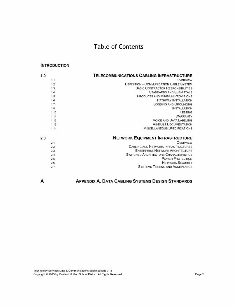
Table of Contents
INTRODUCTION
1.0 TELECOMMUNICATIONS CABLING INFRASTRUCTURE1.1 OVERVIEW1.2 DEFINITION – COMMUNICATION CABLE SYSTEM1.3 BASIC CONTRACTOR RESPONSIBILITIES1.4 STANDARDS AND SUBMITTALS1.5 PRODUCTS AND MINIMUM PROVISIONS1.6 PATHWAY INSTALLATION1.7 BONDING AND GROUNDING1.8 INSTALLATION1.10 TESTING1.11 WARRANTY1.12 VOICE AND DATA LABELING1.13 AS-BUILT DOCUMENTATION1.14 MISCELLANEOUS SPECIFICATIONS
2.0 NETWORK EQUIPMENT INFRASTRUCTURE2.1 OVERVIEW2.2 CABLING AND NETWORK INFRASTRUCTURES2.3 ENTERPRISE NETWORK ARCHITECTURE2.4 SWITCHED ARCHITECTURE CHARACTERISTICS2.5 POWER PROTECTION2.6 NETWORK SECURITY2.7 SYSTEMS TESTING AND ACCEPTANCE
A APPENDIX A: DATA CABLING SYSTEMS DESIGN STANDARDS
Technology Services Data & Communications Specifications v1.8Copyright © 2015 by Oakland Unified School District. All Rights Reserved. Page 2
Document Change History
Version Number
Revision Date
Summary of Changes
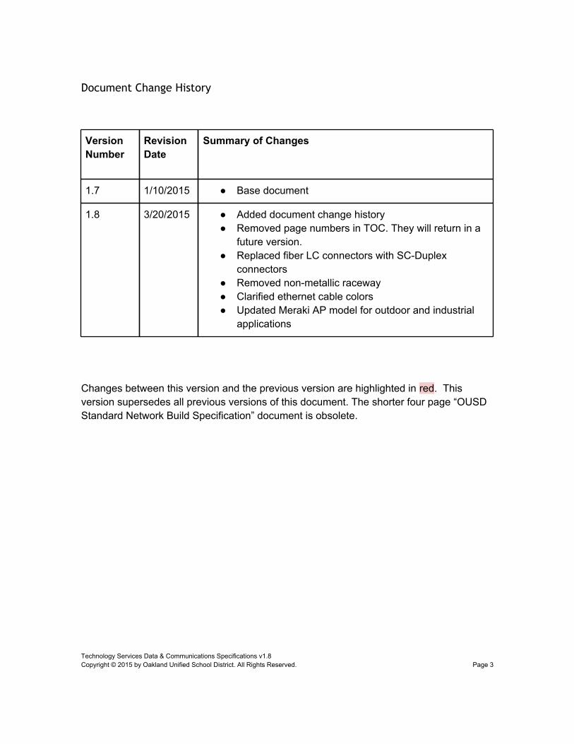
1.7 1/10/2015 ● Base document
1.8 3/20/2015 ● Added document change history● Removed page numbers in TOC. They will return in a
future version.● Replaced fiber LC connectors with SC-Duplex
connectors● Removed non-metallic raceway● Clarified ethernet cable colors● Updated Meraki AP model for outdoor and industrial
applications
Changes between this version and the previous version are highlighted in red. This version supersedes all previous versions of this document. The shorter four page “OUSD Standard Network Build Specification” document is obsolete.
Technology Services Data & Communications Specifications v1.8Copyright © 2015 by Oakland Unified School District. All Rights Reserved. Page 3
Introduction
The Technology Implementation Specifications within this document represent the standards of the Oakland Unified School District (OUSD) for the provisioning and implementation of Information Technology and related systems. Collectively, these specifications address a broad range of technologies, specifically:
● Data Network (e.g., LAN/WAN) Infrastructure – Wired and Wireless● Voice-over-IP (VoIP) Telecommunication Infrastructure
Please note that, wherever a specific manufacturer and/or product is listed, the words “or equivalent” shall be understood to be appended. Such equivalents, however, are subject to OUSD approval.
Technology Services Data & Communications Specifications v1.8Copyright © 2015 by Oakland Unified School District. All Rights Reserved. Page 4
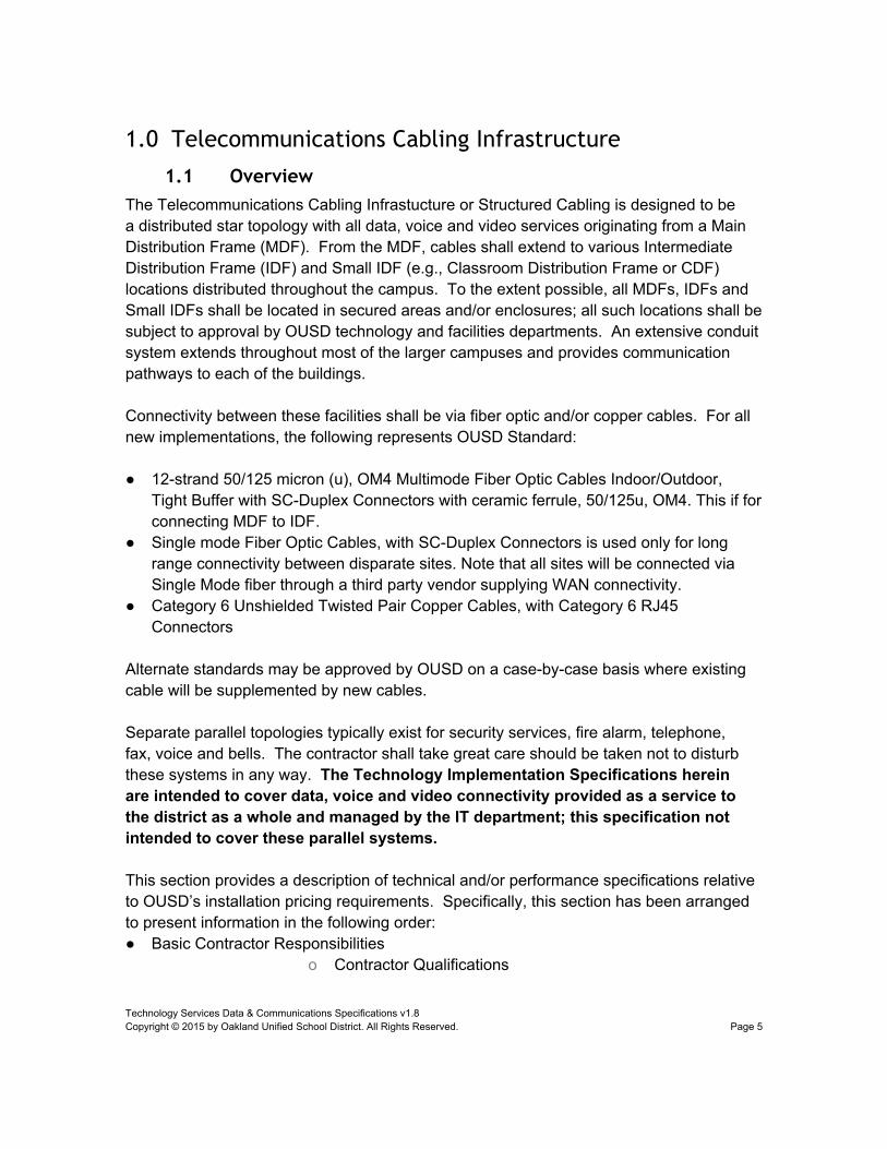
1.0 Telecommunications Cabling Infrastructure
1.1 OverviewThe Telecommunications Cabling Infrastucture or Structured Cabling is designed to be a distributed star topology with all data, voice and video services originating from a Main Distribution Frame (MDF). From the MDF, cables shall extend to various Intermediate Distribution Frame (IDF) and Small IDF (e.g., Classroom Distribution Frame or CDF) locations distributed throughout the campus. To the extent possible, all MDFs, IDFs and Small IDFs shall be located in secured areas and/or enclosures; all such locations shall be subject to approval by OUSD technology and facilities departments. An extensive conduit system extends throughout most of the larger campuses and provides communication pathways to each of the buildings.
Connectivity between these facilities shall be via fiber optic and/or copper cables. For all new implementations, the following represents OUSD Standard:
● 12-strand 50/125 micron (u), OM4 Multimode Fiber Optic Cables Indoor/Outdoor, Tight Buffer with SC-Duplex Connectors with ceramic ferrule, 50/125u, OM4. This if for connecting MDF to IDF.
● Single mode Fiber Optic Cables, with SC-Duplex Connectors is used only for long range connectivity between disparate sites. Note that all sites will be connected via Single Mode fiber through a third party vendor supplying WAN connectivity.
● Category 6 Unshielded Twisted Pair Copper Cables, with Category 6 RJ45 Connectors
Alternate standards may be approved by OUSD on a case-by-case basis where existing cable will be supplemented by new cables.
Separate parallel topologies typically exist for security services, fire alarm, telephone, fax, voice and bells. The contractor shall take great care should be taken not to disturb these systems in any way. The Technology Implementation Specifications herein are intended to cover data, voice and video connectivity provided as a service to the district as a whole and managed by the IT department; this specification not intended to cover these parallel systems.
This section provides a description of technical and/or performance specifications relative to OUSD’s installation pricing requirements. Specifically, this section has been arranged to present information in the following order:● Basic Contractor Responsibilities
o Contractor Qualifications
Technology Services Data & Communications Specifications v1.8Copyright © 2015 by Oakland Unified School District. All Rights Reserved. Page 5
o Panduit design and installation certificationso Provisioning by Contractoro Provisioning by Otherso and pathways Installationso Submittals/Varianceso Acceptance and Subsequent Supporto Other Contractor Responsibilities
● System Documentation and Standardso Standards, Guidelines and Practiceso System Certification and/or Warranties
● Productso MDF/IDF Room Build outso Pathwayso Backbone Cables and Terminationso Horizontal Cables and Terminationso Other
● Installationo Overviewo MDF/IDF Room Buildoutso Pathwayso Backbone Cables and Terminationso Horizontal Cables and Terminationso Miscellaneous Cable Requirementso Labeling Schemeso Testing Procedureso As-Built Documentation
● Miscellaneous OUSD Installation Requirements
1.2 Definition – TELECOMMUNICATIONS CABLING INFRASTRUCTURE
TELECOMMUNICATIONS CABLING INFRASTRUCTURE is defined as all required equipment and cabling including the following: cabinets, racks, splice enclosures, termination blocks, cross-connect wire or cordage, patch panels, patch cords, telecommunication outlets, mounting hardware, wire management, shielded and unshielded twisted pair, sub-duct (innerduct), coaxial and optical fiber cable installed and configured to provide computer data and voice connectivity from each data or voice device to the network file server or voice network/switch designated as the service point of the local area network.
Technology Services Data & Communications Specifications v1.8Copyright © 2015 by Oakland Unified School District. All Rights Reserved. Page 6

Cables and terminations shall be provided and located as shown and in the quantities indicated in the Scope of Work and supported by the drawings. Fiber cables shall terminate in modular patch panels located in all demarcation and termination points shown on the drawings. All cables and terminations shall be identified at all locations. All cables shall terminate in an alphanumeric sequence at all termination locations. All copper cable terminations shall comply with, and be tested to TIA/EIA 568A and TSB-67 standards for Category 6 for data cabling and telephone installations. Station cables shall terminate on appropriate station termination hardware, surface mount or flush mount, equipped as shown on the drawings.
Technology Services Data & Communications Specifications v1.8Copyright © 2015 by Oakland Unified School District. All Rights Reserved. Page 7
1.3 Basic Contractor Responsibilities
Attributes. The Contractor shall, at a minimum, possess the following attributes:
● Current manufacturer certification as a certified designer and as a certified installer of the product to be installed, which shall remain valid during the entire course of the installation agreement, with no known pending action or intent by manufacturer and/or the Contractor to terminate or limit status as a manufacturer certified designer and installer. NOTE: Pending Respondent status as a certified designer and installer is unacceptable.
● At least one prior year of certified status with the manufacturer for the products to be installed, including the right and ability to deliver a completed installation conforming to the manufacturer’s warranty program requirements; additionally, the Contractor must have completed at least five similar projects as a certified designer and installer for the products to be installed.
● Five years of cabling and pathway implementation experience under its current organizational structure, either directly or under wholly owned predecessor entities.
● Profitable status for at least the two preceding fiscal years (three years if privately held and not submitting financial statements).
● No significant pending litigations, which may subject the company to financial risk exceeding twenty percent of its value.
● Insurance coverage as required by OUSD (such as, but not limited to, workers compensation), as well as professional liability coverage of not less than $1,000,000 per occurrence.
● At least one Registered Communication Distribution Designer (RCDD) certified by Building Industries Consultant Services International, including the willingness and intent to assign such personnel to this project as project engineer or project manager.
● Personnel specifically trained and certified under the manufacturer’s installation training program, including the willingness and intent to assign installation project resources in a manner which utilizes certified personnel for each and every project manager and foreman/supervisor position associated with providing services to meet these installation requirements.
Technology Services Data & Communications Specifications v1.8Copyright © 2015 by Oakland Unified School District. All Rights Reserved. Page 8

Provisioning by Contractor.
It shall be the responsibility of the Contractor to provide any cable path engineering and cable system engineering not already provided on drawings issued by OUSD for the subject installation. OUSD or OUSD’s representative, prior to cable placement, must approve any engineered pathways not already depicted on the drawings. The Contractor shall provide a designated project manager to coordinate engineering and construction activity with OUSD or OUSD’s representative throughout the course of this engagement.
The Contractor, except as otherwise indicated herein, shall also:
● Provide and install all materials including, but not limited to: communications cable; station jacks, inserts and faceplates; device boxes and brackets; cable support apparatus; cable runways; cable raceways; conduits, sleeves, firestopping, underground pull boxes, junction boxes, grounding, coring and patching, equipment racks, equipment cabinets, MDF/IDF termination components; firestopping; labeling; testing; etc.
● Provide and furnish all supplemental labor and related services, including, but not limited to: design/engineering, testing, and test equipment, as-built documentation in AutoCAD printed drawings and software file copy format, contract administration, etc., as applicable to expeditiously completing installations at OUSD facilities in accordance with requirements of this Technical Specification
● Provide and furnish all permits
● Satisfy all shipping, tax and other expenses reasonably associated with the Implementation
● Provide and furnish completely installed and certified systems, inclusive of as-built documentation, cable test documentation, manufacturer’s warranties, as well as any and all regulatory signoffs associated with the Implementation.
● Provide and furnish completed lien waivers and lien releases for each supplier or trade subcontractor utilized during the course of the project.
● Coordinate as necessary with OUSD facilities personnel, campus faculty, OUSD’s Representative, and other OUSD contractors, as well as execute installations in accordance with demands of OUSD’s requirements.
OUSD reserves the right to define other Contractor responsibilities before executing a final contract.
Provisioning by Others. Within the fulfillment of each OUSD installation requirement, certain responsibilities are borne by others. The following bullets generally outline the duties of OUSD and OUSD’s representative.
● OUSD’s Representative: For purposes of OUSD’s installation requirements, OUSD Representative’s overall responsibilities include: providing OUSD with advice and design services relative to the communications infrastructure; oversight and/or project management specifically relevant to OUSD’s installation requirements; serve as a liaison between OUSD, the Contractor, campus faculty, various OUSD facilities personnel, and others as applicable but specifically relevant to design, engineering and implementation of OUSD’s infrastructure.
Installation. It is intended that all unshielded twisted pair (UTP) cabling will be installed, tested and certified to meet the latest available draft of TIA/EIA requirements for Category
Technology Services Data & Communications Specifications v1.8Copyright © 2015 by Oakland Unified School District. All Rights Reserved. Page 9
6 cabling installations, as well as other industry standards, guidelines and practices. Fiber optic cabling implemented pursuant to OUSD’s installation requirements shall likewise be installed, tested and certified to meet the latest applicable standards, guidelines and practices. Furthermore, each installation shall be certified to meet the latest available manufacturer’s requirements for an extended warranty of fifteen (15) years minimum duration.
Contractor Submittals/Variances. OUSD’s installations require the submittal of various items as part of the project process. These items include, but are not limited to:
● Identification of and specifications regarding any specification variance (see Variances, below)[1][2]
● AutoCAD plot(s) of pathways and outlet placement drawings, inclusive of proposed outlet numbering layout[1]
● Support details for each pathways system to be installed by Contractor[1]
● Proposed location of termination block(s) supporting MPOE/Tie Cable services at each building MPOE[1]
● Sample outlet, termination and cable labels of each type[1]
● MDF and IDF rack or cabinet elevation drawings[3]
● Fiber optic cable test results from each cable spool (if applicable)[2]
● Current test equipment calibration certifications for each specific test device[2]
● Written notice of scheduled testing (to be delivered at least three business days in advance)[2]
● Detailed cable test result documentation[3]
● Detailed as-built drawings[3]
NOTES: [1] – Constitutes an initial submittal to be provided no later than the date/time specified by OUSD. [2] – To be submitted as necessary prior to commencing affected work. [3] – To be submitted within ten days after completion of each installation (unless otherwise noted).
This Specification and associated documents may specify various required materials, components and processes. To the extent the Contractor intends to deviate from any written or intended specification, a written submittal must be provided to OUSD/OUSD’s Representative and written OUSD approval must be granted prior to proceeding with any variance.
Acceptance and Subsequent Support. Prior to each installation final acceptance, the Contractor will perform complete system tests under the supervision of OUSD and/or OUSD’s Representative. The Contractor will furnish all necessary test equipment and perform all work required to determine or modify performance to meet specifications as described herein. This work shall include, but not be limited to, the following at no extra cost:
● Complete testing of each and every cable pair or fiber strand in accordance with TIA/EIA standards and guidelines
● Submission of detailed, computer generated test results to OUSD/OUSD’s Representatives as required within this Technical Specification
● Adjustment of all components for optimum quality operation as well as for maximum manageability and esthetic quality
Technology Services Data & Communications Specifications v1.8Copyright © 2015 by Oakland Unified School District. All Rights Reserved. Page 10

● Development and provision of complete as-built drawings and other documentation as required within this Technical Specification
● Provision of complete instruction to OUSD’s personnel in the proper operation of the cabling by a qualified representative of the Contractor at a time suitable to OUSD; complete instructions, diagrams and drawings necessary to ensure the success of the training shall be developed by the Contractor and will become the property of OUSD prior to acceptance
OUSD shall either accept the network in writing or notify Contractor in writing, specifying in reasonable detail, those particulars, which OUSD deems unacceptable. With respect to any such particulars, which OUSD deems are unacceptable, the Contractor shall immediately proceed to correct them, and after correction thereof, OUSD shall accept or reject the modifications in writing.
Other Contractor Responsibilities. In addition to the above, the Contractor shall also abide by the following responsibilities:
● Site Cleaning. Throughout the progress of each OUSD installation, the Contractor shall keep the working areas free from debris of all types and shall remove from the premises all refuse resulting from any work performed by the Contractor. On a daily basis and at the completion of its work, the Contractor shall, to the extent possible, leave the premises in a clean and finished condition.
● Safety Requirements. The Contractor will utilize appropriate personnel and display warning signs, signals, flags and/or barricades at the work site to ensure adherence to OUSD, State and industry safety regulations and as prudence requires. Costs for such safety provisions shall be included within each unit pricing cost.
Specification Status. All specifications and requirements related to this project will not be “frozen”, but are subject to change by OUSD and/or OUSD’s Representative.
1.4 Standards and SubmittalsStandards, Guidelines and Practices. As stated earlier, installation and certification of all unshielded twisted pair (UTP) cabling in accordance with the latest available TIA/EIA requirements for Category 6 cabling installations is required.
Structured Communication Cable Systems and Pathways shall be installed in a “neat and workmanlike manner” as specified by ANSI/NECA/BICSI 568-2001 and National Electrical Code, Sections 110-12 and 800-6.
The contractor shall adhere to and comply with the latest versions and/or revisions of each applicable standard. Among the various standards, guidelines and practices applicable to this project are the following:
● BUILDING INDUSTRY CONSULTING SERVICES INTERNATIONAL:
o BICSI Telecommunications Distribution Methods Manual
● CALIFORNIA BUILDING STANDARDS COMMISSION:
o California Electrical Code (1998) Title 24, Part 3
● FEDERAL COMMUNICATIONS COMMISSION (FCC):
o FCC Part 68.5: Establishment of Telephone Premises Wiring Attestation List
Technology Services Data & Communications Specifications v1.8Copyright © 2015 by Oakland Unified School District. All Rights Reserved. Page 11
● INSULATED CABLE ENGINEERS ASSOCIATION (ICEA):ANSI/ICEA S-80-576: Communication Wire and Cable for Wiring of Premises (1994)
● NATIONAL ELECTRICAL MANUFACTURERS ASSOCIATION (NEMA):
o NEMA WC 63: Telecommunications Cables (1994)
● NATIONAL FIRE PROTECTION ASSOCIATION (NFPA):
o NFPA 70: National Electrical Code (1999)
● Public Works Standards, Inc.
o Green Book Standard Specifications For Public Works Construction (2000)
● RURAL ELECTRIFICATION ADMINISTRATION (REA)
o REA 345-165: Digital Stored Program Controlled Central Office Equipment (Form 522) (1989)
o REA TECM 823: Electrical Protection by Use of Gas Tube Arrestors (1980)
● TELECOMMUNICATIONS INDUSTRY ASSOCIATION/ELECTRONIC INDUSTRIES ALLIANCE (EIA)
o TIA/EIA-455-21: FOTP-21 Mating Durability of Fiber Optic Interconnecting Devices (1988)
o EIA-492AAAA: 62.5 uM Core Diameter/125 uM Cladding Diameter Class Ia Multimode, Graded-Index Optical Waveguide Fibers (1989)
o TIA/EIA-526-14A: Optical Power Loss Measurements of Installed Multimode Fiber Cable Plant – OFSTP-14 (August 1998)
o TIA/EIA-568-B.1: Commercial Building Telecommunications Cabling Standard Part 1: General Requirements (May 2001)
o TIA/EIA-568-B.2: Commercial Building Telecommunications Cabling Standard Part 2: Balanced Twisted-Pair Cabling Components (May 2001)
o TIA/EIA-568-B.3: Optical Fiber Components Standard (April 2000)
o TIA/EIA-569: Commercial Building Standard for Telecommunications Pathways and Spaces (June 2001)
o TIA/EIA-570: Residential Telecommunications Wiring Standard (October 1999)
o TIA/EIA-598: Optical Fiber Cabling Color Coding (May 1995)
Technology Services Data & Communications Specifications v1.8Copyright © 2015 by Oakland Unified School District. All Rights Reserved. Page 12

o TIA/EIA-606: Administration Standard for the Telecommunications Infrastructure of Commercial Buildings (February 1993)
o TIA/EIA-607: Commercial Building Ground and Bonding Requirements for Telecommunications (August 1994)
o TIA/EIA TSB-75: Additional Horizontal Cabling Practices for Open Offices (1996)
o TIA/EIA TSB-758: Customer-Owned Outside Plant Telecommunications Cabling Standard (April 1999)
● UNDERWRITERS LABORATORIES INC. (UL)
o UL 444: Communications Cables (1994; R 1995, Bul. 1995 and 1996)
o UL 467: Grounding and Bonding Equipment (1993; Bul. 1994 and 1996, R 1996)
o UL 497: Safety Protector for Paired Conductor Communication Circuit (1995)
o UL 514C: Nonmetallic Outlet Boxes, Flush-Device Boxes, and Covers (1988; R 1989, Bul. 1993 and 1994)
o UL 910: Flame-Propagation and Smoke-Density Values for Electrical and Optical-Fiber Cables Used in Spaces Transporting Environmental Air (1995; R 1995, Bul. 1995 and 1996)
o UL 969: Marking and Labeling Systems (1995)
o UL 1286: Office Furnishings (1993)
o UL 1581: Electrical Wires, Cables, and Flexible Cords (1991; Bul. 1993, 1994, 1995, and 1996, R 1996)
o UL 1666: Flame Propagation Height of Electrical and Optical-Fiber Cables Installed in Vertical Shafts (1991; Bul. 1995 and 1996)
o UL 1863: Communication Circuit Accessories (1995)
Federal, state, local, and OUSD codes, rules, regulations and ordinances governing the work, as well as various additional standards, guidelines and practices, may apply and shall be incorporated as part of these Technical Specifications.
In reviewing the various Contract Documents, the Contractor shall be responsible for noting conflicts between proposed design/concepts and the applicable standards, guidelines and practices. A written Request for Information (RFI) shall be developed by the Contractor and submitted to OUSD and/or OUSD’s Representative prior to commencing any work impacted by such conflicts; such RFIs shall describe the conflict/violation and, if appropriate, recommend alternative solutions with associated costs. OUSD and/or OUSD’s Representative warrants it will diligently strive to address such RFIs in order to minimize negative impact on each installation completion schedule.
Technology Services Data & Communications Specifications v1.8Copyright © 2015 by Oakland Unified School District. All Rights Reserved. Page 13
Where the requirements of the Contract Documents are more stringent than applicable codes, rules, regulations, ordinances, standards, guidelines and practices, the Contract Documents shall apply. In all other instances, the most current standards, guidelines and practices shall apply.
System Certification and/or Warranty. The installation must be certified to meet the manufacturer’s latest available warranty program requirements and delivering to OUSD an extended warranty of at least twenty-five (25) years duration. At minimum, such warranty shall, at no additional cost to OUSD, provide a system warranty covering the installed cabling against defects in workmanship, components and performance. General features of the warranty shall, at a minimum, include:
● An installation warranty extending to protecting OUSD against defects in workmanship for a period of at least one year from the date of system acceptance. Such warranty shall provide all labor and materials necessary to correct a failed portion of the system and to demonstrate performance within original specifications after the repairs are accomplished.
● A system performance warranty extended by the component manufacturer for a period of not less than fifteen (15) years from date of system acceptance. The performance warranty shall warrant the installed horizontal copper and, as applicable, the installed horizontal and backbone fiber optic portions of the system. All such links and segments shall be warranted in accordance with the latest applicable requirements as defined by TIA/EIA.
As outlined herein, OUSD intends that the resulting cabling will be warranted under the extended warranty provisions extended by the manufacturer. The Technical Specification is based on the products being manufactured by Panduit and others. The warranty shall extend to UTP and fiber optic portions of the installation to the fullest extent allowed by the manufacturer.
Submittals. The Contractor is to submit the following prior to construction for OUSD approval:
● Manufacturer's Catalog Data:
o Telecommunications cabling (backbone and horizontal)
o Fiber optic type SC connectors
o Telecommunications outlet/connector assemblies (RJ-11 and RJ-45 jacks)
o Equipment enclosures and support racks
o Patch Panels (Copper and Fiber optic)
o Power Strips
o Cable Hangers
o Floor outlet boxes or modules
o Firestop material
o External mounted raceway
o Cable tray
Technology Services Data & Communications Specifications v1.8Copyright © 2015 by Oakland Unified School District. All Rights Reserved. Page 14
● Drawings:
o Telecommunications Drawings
o Distribution Frame ElevationsTelecommunications Drawings:
o Provide BICSI RUDD-approved drawings complete with wiring diagrams and details required to prove that the distribution system shall properly support connectivity from the MDF to the IDF to the telecommunications work area outlets.
o Show the layout of cabling and pathway runs, MDF, IDF and ground system.
o Drawings shall depict final telecommunications cabling configuration, including location, gage, pair assignment and patch panels after telecommunications cable installation.
o Provide a plastic laminated schematic of telecommunications cable system showing cabling, MDFs, IDFs, SMALL IDFs, and equipment rooms keyed to floor plans by room number.
o Provide two (2) electronic copies of as-built drawings to OUSD; such files shall leverage Autodesk AutoCAD 2003 or later.
● Distribution Frame Elevations:
o Provide shop drawings showing layouts of applicable equipment including incoming IDF racks, patch panels and LAN equipment.
● Statements:
o Installer qualifications
o Test plan
o Professional References
o Labeling Scheme
1.5 Products and Minimum Provisions
The Contract Documents generally outline industry standard components to be installed as part of OUSD’s installation requirements. Such identification is intended to be general in nature rather than exhaustive; all quantities, if stated, are subject to validation by Respondent. Respondent is reminded that differences between estimated quantities and those reasonably derived based from the Contract Documents (as well as through bid conferences, job walks, RFB addendums, and other distribution of information) shall be the responsibility of the Contractor; there shall be no additional cost incurred by OUSD for complying with the specifications and requirements of the Contract Documents.
Any variance from those components identified on the drawings and/or below shall be submitted to OUSD/OUSD’s Representatives for approval prior to ordering and installation;
Technology Services Data & Communications Specifications v1.8Copyright © 2015 by Oakland Unified School District. All Rights Reserved. Page 15

the risk for all costs incurred by the Contractor for materials ordered prior to such written approval shall be borne entirely by the Contractor. Nonetheless, it is imperative that the Contractor determine the availability of necessary materials and propose equivalent substitutes as necessary to meet all installation milestones; delays in installations due to lack of product availability are unacceptable. As catalog numbers change frequently, the Contractor must verify all part numbers prior to ordering materials. Clarifications will be issued in response to written Requests for Information (RFIs)
All UTP, fiber optic cabling, innerduct and cable ties, where required, will be plenum-rated (i.e., CMP, ONFP). Copper and fiber optic backbone cable intended for installation within conduit, riser shafts and chases, etc., shall be at a minimum, rated CMR (riser rated). Unrated cable (such as filled ASP) shall not be installed within the structure except when placed within EMT, IMC, PVC or RGS conduit.
Delivery and Storage. Contractor shall provide protection from weather, moisture, dirt, dust and other contaminants for telecommunications cabling and pathway equipment placed in storage.
Components. Components shall be UL or third party certified. Provide a complete system of telecommunications cabling and pathway components using star topology and support structures, pathways, and spaces complete with conduits, pull wires, raceways, junction boxes, underground pull boxes, outlets, and cables, as per OUSD requirements. Fixed cables and pathway systems for telecommunications systems shall be UL listed or third party independent testing laboratory certified, and shall comply with NFPA 70. Horizontal cable shall be General or Mohawk or OUSD approved equivalent, and termination equipment shall be Panduit or OUSD approved equivalent and installed and certified so as to provide a 25-year warranty.
Pathways (Backbone & Horizontal). Pathways shall consist of conduits; pull boxes, sleeves, cable runway, raceways, ceiling hangers, J-Hooks and outlet boxes as per the drawings. Provide grounding and bonding as required by TIA/EIA-569 and TIA/EIA-607.
Distribution Frames. Provide main distribution facilities (MDFs) and intermediate distribution facilities (IDFs), as required per each installation site walk for terminating and cross connecting permanent cabling links.
Equipment Enclosures. Equipment cabinets shall consist of frame, sides, top, front door and back door. Perforated doors shall be provided for enclosures within secured rooms, but solid doors are required within classrooms and other rooms/areas where students may be present. Lockable front and louvered/perforated lockable back doors are required. Enclosure frames and doors shall be made of 16-gauge high quality cold rolled steel (CRS) throughout in an all-welded construction. Enclosure side panels and top panels shall be made of minimum 18-gauge high quality cold rolled steel (CRS). Cabinet finish color shall be determined by OUSD, modular type steel construction and treated to resist corrosion.
The following additional requirements apply:
● Enclosure Top Panel is to be perforated to allow for heat exhaust as well as adaptable for fan assembly options.
● Enclosure should have three (3) cable access panels located at base of cabinet on each side and at the back for cable access when cabinet may not be on raised floor or cable entry is not coming from the ceiling.
● Enclosure shall have a 1,000 pound loading capacity.
Technology Services Data & Communications Specifications v1.8Copyright © 2015 by Oakland Unified School District. All Rights Reserved. Page 16
● The enclosure shall provide 19” rack mounting.
● Dimensions shall be approximately 84”H X 24” W X 36” D. Seismic bracing shall be installed.
● A 315 CFM top mount fan assembly enclosed within a fan housing and supplied with 6 foot power cord shall be provided within all enclosures.
● The equipment enclosure shall be Cooper B-Line E2-SC-842436-19-BL or OUSD approved equal.
Equipment Racks. Equipment racks shall be freestanding modular aluminum units designed for telecommunications terminal support and coordinated with dimensions of units to be supported. Equipment racks shall have approximate module dimensions of 84 inches high by 19 inches wide by 3 inches channel depth. Additional characteristics of the equipment racks shall be as follows:
● All high strength, lightweight 6061-T6 aluminum extrusion construction.
● Equipped with two top angles or top bars and heavy-duty assembly hardware.
● Have EIA hole pattern on front and rear.
● Assemble to provide 19-inch mounting with no additional hardware.
● Have:
o EIA Channel: 3" x 1.265" x 1/4" thick flange
o Base Angles: 3 1/2" x 6" x 3/8" thick (pair)
o Top Angles: 1 1/2" x 1 1/2" x 1/4" (pair).
o Top Bars: 1 1/2" x 1/4" (pair).
● A weight capacity of 1000 lb (weight must be evenly distributed).
● Clear coated over a brushed aluminum finish.
● Provide floor and ceiling access for cable management and distribution.
● Provide a pre-drilled base for floor attachment of rack.
Equipment racks shall be earthquake braced.
Equipment racks shall be Cooper B-Line SB-556-084-XU or OUSD approved equivalent.
Wire Management. All 84” tall equipment racks shall be equipped with vertical wire management organizers. All equipment racks, wall mount racks and wall mount cabinets shall be equipped with horizontal wire management.
All horizontal wire managers shall be heavy duty painted black metal units designed specifically to connect to equipment frames. All vertical wire managers shall be aluminum with a black finish. All wire managers shall be secured to the frames and shall provide a clear and unobstructed pathway in which to route the cables. Each UTP and fiber optic patch panel will have one (1) 2RU horizontal wire manager above and below.
Vertical Wire Managers. Vertical wire managers shall be six inches wide and seven feet tall. Vertical wire mangers shall have evenly spaced wire rings designed to maintain jumper, patch, or cross-connect wire in place.
Technology Services Data & Communications Specifications v1.8Copyright © 2015 by Oakland Unified School District. All Rights Reserved. Page 17

Vertical wire managers shall be designed to extend past the frame to allow placement of equipment in any position within the rack. When mounted between equipment frames, they shall be designed to direct cables into either frame and shall be securely mounted to both units. Vertical wire managers shall be equipped with cable restraint latches.
Vertical wire managers shall be Cooper B-Line-SB-63S-084 or OUSD approved equivalent.
Equipment Rack – Wall-Mounted. Wall-mounted equipment racks shall have approximate module dimensions of 36 or 48 inches high by 19 inches wide by 3 inches channel depth. Additional characteristics of the equipment racks shall be as follows:
● All high strength, lightweight 6061-T6 aluminum extrusion construction.
● Rated for 350 lb. load capacity (dependant on wall characteristic)
● Have EIA hole pattern on front and rear.
● Assemble to provide 19-inch mounting with no additional hardware.
● Have an EIA Channel 3" x 1.265" x 1/4" thick flange.
● Be clearcoated over a brushed aluminum finish.
● Provide access for cable management and distribution.
● Provide pre-drilled base for wall attachment of rack.
Wall-mounted equipment racks shall be mounted on plywood backboard in location to be determined.
Wall-mounted equipment racks shall be manufactured by Cooper B-Line or OUSD approved equivalent.
Equipment Cabinet – Wall-Mounted. Wall-mounted equipment cabinets shall be fully enclosed, lockable, modular type steel construction and treated to resist corrosion. Such cabinets shall be wall mount/swing out type, providing 19” rack mounting, and designed to allow for left or right-hand swing. While cabinet size will be determined on a project-by-project basis, default dimensions shall be approximately 36”H X 24” W X 24” D or 48”H X 24” W X 24” D. An optional 210 CFM side mount fan assembly supplied with power cord shall be available. Cabinet finish color shall be determined by OUSD.
Cabinet shall be mounted on plywood backboard in location to be determined.
Cabinets shall be manufactured by Cooper B-Line or OUSD approved equal.
Cable Runway. Cable runways (ladder rack) shall be provided to permit installation of communications, computer, CATV, paging, distribution system cables and other low voltage system cables. Cable Runway: Runway (ladder rack) shall be constructed of an open bottom with 1½” cable bearing surface 12” on center. Side rails shall be minimum 1 ½” high and constructed of tubular steel. Finish shall be black baked enamel.
Accessories and special transitions shall be provided for all changes in direction and offsets. Use manufacturer’s standard fittings, including bolting assemblies for all end-to-end connections. Provide transverse and longitudinal seismic restraints as required. Provide plastic trough dropout bushings at each location where cables will descend into the equipment racks.
Technology Services Data & Communications Specifications v1.8Copyright © 2015 by Oakland Unified School District. All Rights Reserved. Page 18

Cable runway wall angle supports shall be steel angles, black baked enamel finish. Ends to be smooth without hooks or projections. Brackets shall be able to support an end load of 600 lb. with a safety factor of 1.65.
Cable runway elbows, tee’s, 90 degree bends and crosses: All horizontal and vertical 90 degree elbows, tees, 90 degree bends and crosses shall be made with right angle couplings which clamp to the runway without the need for drilling or cutting.
Cable runway shall be manufactured by Cooper B-Line or OUSD approved equal.
Backboards. MDF and IDF walls shall be covered with ¾-inch thick, Grade A/C, void-free, fire rated plywood, as required. 3/4 inch thick by 8 feet-0 inches high A/C plywood. Backboards shall be mounted vertically, starting 6 inches above the finished floor, and secured to the walls. All backboards are to be constructed of 4 feet by 8 feet plywood. All plywood panels must be mounted in contact with one another, leaving no gaps between sheets.
At OUSD designated wall-mount IDF rack and cabinet locations, the Contractor shall install ¾-inch thick, Grade A/C, void-free, fire rated plywood of adequate height and width to support the mounting of wall mount racks or cabinets.
Cabinet Specifications Summary
0. All Cabinets: Minimum 48” cabinet is required. Other (36” or 24” cabinets) are permitted with OUSD permission
● Use 24 and 48 port patch panels to accommodate 48 port switches.● Structured cabling solution is:
o Cable by General Cableo Termination by Panduito Patch cable and jack is blue for data jacks in work areas and classrooms.o Patch cable and jack is orange for Wireless APso Patch cable and jack is red for building systems, including fire alarm,
environmental systemso Patch cable and jack is green for security cameraso Patch cable and jack is white for voice and bell/clock systems
a. Cabinet in MDF
Install full-size, floor-mounted, fully enclosed, lockable cabinet in MDF, minimum of one cabinet per MDF. (Note: if there is insufficient room for a fully enclosed cabinet, a two-post aluminum rack may be substituted only with the written permission of from the OUSD Facilities or Technology Departments).
b. Cabinets in Large IDFs (greater than 48 terminations)
Install full-size, floor-mounted, fully enclosed, lockable cabinet in each IDF, minimum of one cabinet per IDF. (Note: if there is insufficient room for a fully enclosed cabinet, a two-
Technology Services Data & Communications Specifications v1.8Copyright © 2015 by Oakland Unified School District. All Rights Reserved. Page 19

post aluminum rack may be substituted only with the written permission of the OUSD Facilities or Technology Departments).
0. Cabinets in Small IDFs (48 terminations or fewer)
Install one 16-gauge wall-mount cabinet with dual hinged lockable solid doors (front and back), having minimum dimensions of 36" high x 30” depth" x 24" wide and maximum dimensions of 48" high x 30" depth x 24" wide, 250 cfm exhaust fan, drilled EIA standard hole spacing, and vented side panels for mounting equipment specified herein at the Small IDF.
MDF and IDF backboards shall be equipped with sufficient quantities of 2” and 4” ‘D’ rings.
Grounding and Bonding Products. The Contract shall comply with UL 467, TIA/EIA-607, and NFPA 70. Components shall be identified as required by TIA/EIA-606.
Firestopping Material. Contractor shall provide all necessary fire stopping of openings through which cable is installed under this specification, in accordance with NFPA 70 and all local codes. This includes installation in conduits, raceways, or bare penetrations. Provide and install UL 1479 approved (Fire Barrier Caulk) firestop material.
Power Strip. The Contractor shall provide and install at each MDF and IDF one (1) rack-mounted Cooper B-Line surge suppressor 12-outlet power strip, or OUSD approved equivalent.
MDF Shelving. The Contractor shall provide and install at each MDF one (1) Cooper B-Line SB-596S-19-15-02M double sided shelf and one (1) B-Line SB-745S-19-16 low profile shelf. At OUSD’s request, an optional Cooper B-Line SB-743KB-19 shall be provided and installed by the contractor.
Surface Mounted Raceway. All cable pathways shall be concealed within walls, whenever possible.
Surface mounted raceway is to be utilized in dry interior locations only as covered in Article 352 part B of the National Electrical Code, as adopted by the National Fire Protection Association and as approved by the American National Standards Institute. All surface-mounted raceway shall be listed as suitable for use in applications having up to 600 volts between conductors by Underwriters Laboratories, Inc., when screw secured and installed per instructions.
Metal Raceway. Metallic surface mounted raceway shall be Wiremold 4000-type metallic or Hubbell 4000 series metallic surface mounted raceway. A full compliment of fittings shall be available including but not limited to mounting clips and straps, couplings, flat, internal and external elbows, cover clips, tees, entrance fittings, conduit connectors and bushings.
A series of inserts shall also be available for retrofit applications that provide a controlled 2" cable bend radius which meets the specifications for Fiber optic and UTP/STP cabling and exceeds the TIA 569 requirements for communications pathways.
Notching or modifications of raceway and fittings will not be permitted.
Copper Patch Panels. Patch panels shall consist of a metal patch panel with four (4) or six (6) port faceplates, which are removable from the front. Such panels shall:
● Mount to standard EIA 19” racks
Technology Services Data & Communications Specifications v1.8Copyright © 2015 by Oakland Unified School District. All Rights Reserved. Page 20
● Be modular, accepting all modules designed for that product line
● Be available with labels that follow TIA/EIA 606 labeling standards.
● Be manufactured by Panduit or OUSD approved equal.
One patch panel port shall be provided for each workstation cable served from the MDF, IDF or SMALL IDF, with a minimum of 12 spare ports required. The Contractor shall supply and install as many patch panels as necessary to service all workstations, plus the required spare count. Quantities of modules shall be based on the number of UTP cables originating at wall outlets and terminating at the patch panel.
Fiber Optic Patch Panels. The Contract shall provide fiber optic patch panels as necessary for the maintenance and cross connecting of fiber optic cables. Such panels shall be constructed of 0.125-inch minimum aluminum and shall have connectors which interface the inside plant fiber optic jumper cable with the outside plant fiber optic cable. These units will terminate the fiber optic cables, provide a place for jumper cables and will provide room to terminate additional optics.
Panels shall be sized to support a minimum of 100% growth. Rack-mounted and wall-mounted fiber patch panels shall be equipped to terminate or splice the incoming inter-building fiber and any required backbone or interconnect cables. Each fiber optic cable must be properly dressed.
All rack-mounted fiber optic patch panels shall be Panduit FRME36EBL, FRME54EBL or FRME72EBL or OUSD approved equal. All wall-mounted fiber optic patch panels shall be Panduit FWME12EBL, FWME24EBL or FWME48EBL or OUSD approved equal.
The fiber optic patch panel connections shall provide 0.4 dB or less insertion loss. All fiber optic connectors will be Panduit FSCMBL type SC or OUSD approved equivalent.
Wire Management. All equipment racks, wall-mount racks, and wall-mount cabinets shall be equipped with horizontal wire management. All horizontal wire managers shall be heavy duty painted black metal units designed specifically to connect to equipment frames. All vertical wire managers shall be aluminum with a black finish. All wire managers shall be secured to the frames and shall provide a clear and unobstructed pathway in which to route the cables.
Each UTP and fiber optic patch panel will have one (1) horizontal wire manager above and below. The in-frame horizontal managers shall be 2RU in height and shall extend from side rail to side rail. Horizontal wire managers shall be equipped with a 3” X 3” slotted duct and cover on front and a 2” X 5” slotted duct and cover on back. Horizontal wire managers shall be equipped with bend radius control clips and strain relief clips. Horizontal wire managers shall be Panduit-WMPH2 or OUSD approved equivalent.
Communications Cabling. All communications cabling used throughout this project shall comply with the requirements as outlined in the National Electric Code (NECÒ) Articles 725, 760, 770, and 800 and the appropriate local codes. All copper cabling shall bear CM, CMP (Plenum Rated), CMR (Riser Rated) and/or appropriate markings for the environment in which they are installed. All optical fiber cabling shall bear OFN, OFNP (Plenum Rated), OFNR (Riser Rated) and/or appropriate markings for the environment in which they are installed. Indoor/Outdoor rated cable shall be used where required.
● Fiber Optic Backbone Cabling:
Technology Services Data & Communications Specifications v1.8Copyright © 2015 by Oakland Unified School District. All Rights Reserved. Page 21
o Multimode fiber optic cables shall be 50/125 micron for all new installations manufactured by Corning or AMP/Pirelli or OUSD approved equivalent.
o The Contractor shall provide all required count (per OUSD requirements) optical fiber cables.
o All fiber optic cables for interior use shall be tight buffered, and shall be marked OFNP per NEC Table 750-50 (e.g., non-conductive plenum rated).
o Fiber optic warning tags shall placed on exposed fiber optic backbone cables.
o Fiber optic warning tags shall be orange in color.
o Fiber optic warning tags shall contain “Caution Fiber Optic Cable”. The text shall be permanent, black, block, letters, at least 3/16” high.
● Fiber Optic SC-style Connectors
o All fiber optic termination connectors will be type SC.
o The fiber optic patch panel connections shall provide 0.4 dB or less insertion loss.
o The fiber optic LC-style connectors shall be manufactured by Panduit or OUSD approved equivalent.
● Fiber Optic Patch Cables.
o Fiber Optic Patch Cables shall be multimode patch cords pre-made to connect fiber optic equipment with fiber optic cross connects, interconnects and outlets.
o The fiber optic patch cables (jumpers) shall be impact-resistant duplex fiber cables, with SC-Duplex connectors as appropriate for installed equipment, of the same performance characteristics as the multimode fiber backbone being connected.
o These fiber optic patch panel connections shall provide 0.4 dB or less insertion loss and provide connection between the Active LAN devices and the Fiber Optic patch panel. Quantities for 100% population plus 10% Spares.
o The fiber optic patch cables shall be available in 2-meter lengths.
o The fiber optic patch cables shall be manufactured by Panduit or OUSD approved equivalent.
● Horizontal Cabling
o Horizontal cabling shall comply with NFPA 70, NEMA WC 63, EIA TSB-36, EIA TSB40-A, ANSI/ICEA S-80-576, EIA TSB-67 and performance characteristics in TIA/EIA-568-B.1 and B.2 standards for UTP, four-pair 100 ohm cabling.
Technology Services Data & Communications Specifications v1.8Copyright © 2015 by Oakland Unified School District. All Rights Reserved. Page 22

o Horizontal cabling shall provide four each individually twisted pair, 24 AWG or 22 AWG conductors enclosed by an overall jacket.
o Overall diameter of four pair cable shall not exceed 0.25 inches.
o Ultimate breaking strength shall be minimum 90 pounds.
o Four pair cable shall withstand a bend radius of one-inch minimum at a temperature of minus 20 degrees C maximum without jacket or insulation cracking.
o Conductors shall be color coded and polarized in accordance with TIA/EIA-568-B.1 and B.2.
o Category 6 cable for telephone systems and local area networks shall exceed TIA/EIA-568-B.1 and B.2 standards and requirements. [NOTE: Lesser standards may apply on a case-by-case basis.]
o Conductor shall be 22 or 24 AWG solid annealed copper.
o Cable shall be plenum rated where required and shall comply with NFPA 70, UL 444, and UL 910.
o Category 6 cable jacket color be according to the cable color specifications.
o Horizontal cabling shall be manufactured by General, Mohawk, or OUSD approved equivalent.
o Category 6 cable runs for data shall not exceed 100 meters in length.
● Work Station Outlet Assemblies
o Jacks shall comply with FCC Part 68.5, and TIA/EIA-568-B.1 and B.2.
o Jacks shall accommodate UTP or OFN and work in concert with Wiremold metallic raceway. Non-metallic raceway is not permitted.
o UTP jacks for data shall be RJ-45 designation T568B type, UL 1863 listed, eight position, constructed of high impact rated thermoplastic housing rated for Category 6 service.
o UTP jacks for data shall be Category 6 hardware and shall comply with the attenuation requirements contained in TIA/EIA-568-B.1 and B.2.
o UTP Jacks for data shall be blue in color except for AP which is orange on both wall and patch panel
o UTP jacks shall be Panduit Category 6 Mini-Com CJ688OT3R or OUSD approved equivalent.
Technology Services Data & Communications Specifications v1.8Copyright © 2015 by Oakland Unified School District. All Rights Reserved. Page 23
o UTP jacks for voice, clocks, bells and speakers shall be off white in color.
o Workstation outlet assemblies shall include Panduit CFPE2IW and CFPE42IW faceplates and CBX2IW-A and CBX4IW-A surface mount boxes
o Stenciled lettering for voice and data circuits shall be provided using thermal ink transfer process.
UTP Patch Cables. UTP patch cables for unshielded twisted pair cable shall be Category 6 rated for Category 6 horizontal cable installations. Such cables shall be equipped with factory-attached connectors to interconnect equipment mounted on the racks of the distribution frame and to connect computer stations to outlet locations. UTP patch cables shall be available in 3’, 5’, 7’, 10’ and 14’ lengths for MDF, IDF, SMALL IDF and workstation locations. UTP patch cables may also be used for patching applications, not to exceed 20 feet. Quantities required shall provide for 100% port population with 10% spare.
UTP patch cables shall be manufactured by Panduit or OUSD approved equal.
Miscellaneous Equipment:
● Conduit Sealer Kit - Semco #PR-851
● Aluminum Threaded Innerduct Couplings - Pyramid Products Part#FO9006
● Corrugated Fiber Optic 1” Innerduct - Carlon Products Part# CID100-T (Orange & Yellow, and Blue)
● Fiber Optic Innerduct Labels - Panduit or Wiremold #PVL 200 BY
● 900 Micron Buffered Fiber Label - Panduit or Wiremold #PMDR-0-9 GMM polyester film marker tape as a “flag”
● Fiber Optic Caution Tag - Osburn #FO4002 1-3/4” x 3-1/2”
Unspecified Equipment & Material. Any item of equipment or material not specifically addressed on the drawings or in this document and required to provide a complete and functional installation shall be provided in a level of quantity and quality consistent with other specified items.
1.6 Pathways Installation
Cable Pathway. Comply with OUSD, TIA/EIA-569, NEC and CEC.
In suspended ceiling areas where duct, cable trays or conduit are not available, the Contractor shall bundle, in bundles of 48 or less, station wiring with cable ties snug, but not deforming the cable geometry. Cable bundles shall be supported via "J" hooks attached to the existing building structure and framework at a maximum of four-foot intervals. Properly rated cable ties will be used in all appropriate areas. The Contractor shall adhere to the manufacturers’ requirements for bending radius and pulling tension of all data and voice cables. Cables shall not be attached to lift out ceiling grid supports or laid directly on the ceiling grid. Cables shall not be attached to or supported by fire sprinkler lines, HVAC ducting, electrical EMT, lighting fixture or any environmental sensing device located in the ceiling air space. All cable shall be run in transverse or longitudinal paths.
Technology Services Data & Communications Specifications v1.8Copyright © 2015 by Oakland Unified School District. All Rights Reserved. Page 24

Use of existing signal and other conduit must be approved in advance by OUSD. The contractor shall be responsible for all replacement cost for damage to cables currently occupying existing conduits.
Conceal interior conduit under floor slabs and within finished walls, ceilings, and floors where possible. Run conduits in crawl spaces and under floor slabs as if exposed. Install conduit parallel with or at right angles to ceilings, walls, and structural members where located above accessible ceilings and where conduit is visible after completion of project. Keep conduit minimum 6 inches away from parallel runs of electrical power equipment, flues, steam, and hot water pipes. Install no more than two 90-degree bends for a single horizontal cable run.
Run raceway as determined by site survey.
Any transitions between buildings or structures shall include an appropriate liquid tight flex joint with a drip loop. Provide pullboxes with liquid tight flex conduit only where flexible connections are required. OUSD approval required prior to all liquid tight flex conduit installations.
New underground conduit shall be 1”, 2” or 4” PVC schedule 40. All sections shall be permanently glued together. Transition from underground PVC to above ground stub up shall be via rigid conduit.
All conduits shall be properly reamed and bushed with pull ropes installed.
Conduits terminating inside of building through floor shall be installed so that the conduit extends a minimum of 4” above finished floor. Conduits terminating inside of building through wall shall terminate in appropriately sized junction box.
Empty conduits shall be plugged with mechanical type seals to ensure that foreign matter does not enter the building. All empty conduits shall be equipped with mechanical type seal plugs in all pull boxes, junction boxes and within all buildings.
All conduits, sleeves and other penetrations will be firestopped by the Contractor prior to acceptance. Such firestopping shall conform to OUSD’s requirements and shall be implemented in accordance with UL design guidelines for fire-rated assemblies.
Provide all coring, patching and painting as needed for Intra-Building and Inter-Building pathways. Caulking is not an acceptable patching method for conduit penetrations into exterior walls. Coordinate with OUSD for acceptable patching methods.
Underground Pull Boxes and Junction Boxes. Underground pull boxes shall be made of concrete and the minimum size shall be 35 ½” x 17 ½” x 12”. Underground pull box covers shall be rated for traffic (type T.05) and shall be marked communications. Metal covers shall be used in all location subject to vehicle traffic.
Underground pull boxes and junction boxes shall not be placed in areas subject to flooding. Gravel shall be installed below all Underground pull boxes for drainage. Establish drainage to meet Public Works Construction Standards (Green Book).
Unless otherwise noted, exterior junction boxes shall have minimum dimensions of 24” x 24” 6”. Interior junction boxes shall consist of 16 gauge steel minimum, unless otherwise noted on plans. Indoor enclosures shall conform to NEMA Type 4, unless otherwise noted. Size junction boxes to not less than minimum Code requirements. Increase size above Code requirements where necessary to provide space for pulling, racking or splicing enclosed conductors, or where specified or indicated dimensions exceed Code requirements.
Technology Services Data & Communications Specifications v1.8Copyright © 2015 by Oakland Unified School District. All Rights Reserved. Page 25

Exterior metal junction boxes exposed to weather (and not installed in or below grade) shall be equipped with rain-tight or weatherproof-hinged doors. Exterior junction boxes shall have 16 gauge steel bodies and 14 gauge steel doors. Exterior pull boxes shall be equipped with stainless steel door clamps on three sides, a removable stainless steel continuous hinge pin, a hasp and staple for padlocking, and external mounting feet.
Enclosures installed on vertical exterior walls shall conform to NEMA Type 3R. Enclosures installed on exterior horizontal surfaces such as rooftops or breezeways shall conform to NEMA Type 4 unless otherwise noted. Rain tight or weatherproof boxes shall use threaded watertight hubs for top or side entry and may use knockout for bottom entry only.
Exterior pull boxes shall conform to these industry standards:
● UL 508 Type 4
● NEMA/EEMAC Type 3, Type 4, Type 12, Type 13
● JIC standard EGP-1-1967
● CSA Type 4
● IEC 529, IP66
Junction Boxes shall be labeled “Communications” with screw on 1/8” engraved, black plate, white letters.
Tamper resistant screws shall be used on all exterior aboveground junction boxes that are exposed to public/student areas.
Exterior pull boxes shall be manufactured by Hoffman or OUSD approved equal.
Communication Duct-Banks and Conduits. Use of existing signal and other conduit must be approved in advance by OUSD.
Trenches. All underground trenches shall be 24” wide by a minimum of 30” deep. Trenches shall be back-filled at 95% compaction. Contractor shall contact Dig Alert a minimum of 48 hours prior to excavation to verify the location of existing underground utilities. Modifications to pathway design may be dictated by field conditions subject to approval by OUSD. Conduits must be inspected by OUSD’s facilities inspector prior to backfill. Contractor shall restore surface to same or better condition. Compaction testing notification must be provided to OUSD 48 hours prior to testing so that an OUSD inspector may be present.
Slurry fill trenches to within three inches (3”) of finished grade whenever crossing paved areas. “Two Sack” slurry shall be used. Pavement removal and patching shall conform to specifications and standards listed in the Public Works Standards (Green Book 2000).
Underground Conduit. All communications conduits shall be placed in a uniform manner between ground boxes and pull boxes. Conduit in position #1 at one ground box or pull box shall maintain its position within the duct run and terminate in the #1 position at the next box. The position of all conduits between ground boxes and pull boxes shall be maintained.
Long radius bends (over 30 feet) shall be used whenever possible to make changes in direction. If it is found to be necessary to place a 90-degree bend in the conduit run, a factory-made sweep of no less than 60-inch radius shall be used. No conduit run shall exceed a total of 180 degrees of bend between any two points (such as manholes or buildings) considering both vertical and horizontal sweeps. Cold-formed trench bends shall have a radius of not less than 60 inches and shall pass mandrel integrity. Bend radius criterion is 2" or less 6 times the diameter of the conduit and any conduit larger than 2" is 10
Technology Services Data & Communications Specifications v1.8Copyright © 2015 by Oakland Unified School District. All Rights Reserved. Page 26

times the diameter of the conduit.
Where communications and power conduits occupy the same trench, all conduit structures shall be built with the telecommunications conduits placed above the power conduits and separated by a minimum of 12” of compact earth or 3” of concrete encasement, unless otherwise called out and approved by OUSD. If this type of construction is required, it shall receive the prior approval of the contractor and OUSD.
Conduit shall have a factory formed bell on one end for interconnecting segments. All conduits shall be equipped with mechanical seal plugs in all ground boxes and expansion rubber seal plugs within all buildings.
Conduit located under heavy use highways or railroad rights-of-ways shall be encased in steel casing consistent with the AASHTO or AREA specifications. The thickness of the steel casing shall be engineered for each specific application. This may vary based on campus codes.
High impact spacers shall be used in all multi-duct systems, for both solely owned and joint telecommunications/power construction. A horizontal and vertical separation of 1 inch between the ducts shall be maintained by installing high impact spacers with horizontal and vertical locking intervals of ten feet. Spacers shall conform to NEMA TC-2, TC-6, TC-8, and ASTM F 512 dimensions.
Utility marking tape shall be buried 18 inches above the conduits.
The length and destination of all conduits shall be identified in each ground box, pull box and building. Embossed metal or heavy plastic tags strapped to each conduit shall be used.
After installation of communications conduits, the contractor shall prove all conduits by pulling a mandrel with a diameter ¼ inch smaller than the conduit and 6 inches long through each conduit end-to-end. An inspector designated by the contractor and OUSD shall be notified 24 hours before this procedure. Each conduit shall be cleaned with a bristle brush to remove any debris.
All conduits shall be equipped with seal plugs in all pull boxes and expansion rubber seal plugs within all junction boxes and building entrances.
Contractor shall install new ¼” pull rope in all conduits placed.
Overhead Conduit. OUSD prohibits the installation and use of overhead conduit extending between buildings.
Communications Entrance Conduit. To prevent shear, all inter-building conduit transitions (either underground or aerial) shall transition from PVC or metal to Sealtight conduit when attaching between permanent structures. The contractor and OUSD shall determine the placement of all entrance conduits. All applicable standards (i.e., OUSD, NEC, BICSI or G.O. 128) shall be adhered to.
Transition from underground PVC to above ground stub up shall be via rigid conduit. Sealtight flex conduit drip loop lengths shall not exceed 24”, unless approved by OUSD.
Conduits terminating inside of building through floor shall be installed so that the conduit extends a minimum of 4” above finished floor. Conduits terminating inside of building through wall shall terminate in appropriately sized junction box.
Provide all coring, patching and painting as needed for Intra-Building and Inter-Building pathways. Caulking is not an acceptable patching method for conduit penetrations into exterior walls. Coordinate with OUSD for acceptable patching methods.
Technology Services Data & Communications Specifications v1.8Copyright © 2015 by Oakland Unified School District. All Rights Reserved. Page 27
All conduits shall be properly reamed and bushed. Contractor shall install new ¼” pull rope in all conduits placed. Empty conduits shall be plugged with mechanical type seals to ensure that foreign matter does not enter the building.
Ductbank Locating Cable (e.g., electronically detectable warning tape). Warning tape shall be a minimum of 3" wide, orange in color, and shall have a non-degradable imprint as follows:
“Caution Fiber Optic Cable Buried Below”
The tape shall be electronically detectable.
Pull Rope. Pull rope shall be new ¼" polypropylene over polyester rope with a minimum 1700 lb. Tensile strength. Pull rope shall be new material that is free of knots, kinks, and abrasions and shall be placed as a single continuous length in every new conduit. Pull rope shall be secured at each end.
1.7 Bonding and Grounding
MDF/IDF Grounding. All MDF Racks shall be provided with a Telecommunications Grounding Busbar (TGB), installed in accordance with TIA/EIA-607. The TGB shall be grounded to the nearest access to the building ground with a #6 AWG insulated conductor. Building ground is identified as building structural steel, or ground rod; gas pipes and electrical conduits are not acceptable ground attachment points.
Ground conductors are not to exceed 40’. If building ground connection is beyond 40’, Contractor is to install a new ground round at the nearest outside location. The ground rod location shall be approved by OUSD prior to installation.
The Contractor shall provide ohms testing for ground. Ground connections shall not exceed 5 ohms. MDF ground rods shall consist of:
● Fargo clamp: Shall be cast from copper, silver-plated, and furnished with copper bolt. Ground rod: shall be manufactured of high strength high carbon steel, with electrolytically bonded jacket of copper on surface, and meet UL spec. 467 and ANSI C-33.8-1072.
1.8 Installation
General Installation Practices. The Structured Communication Cable System and pathway, including the horizontal and backbone cable, pathway systems, telecommunications outlet/connector assemblies, and associated hardware shall be installed in accordance with TIA/EIA-568-B.1 and B.2, TIA/EIA-569, NFPA 70, and UL standards as applicable.
Cabling shall be connected in a star topology network. Installation methodologies shall adhere to manufacturer installation procedures so as to not violate certifications (i.e. UL). All work shall be performed in a good workmanship-like manner leaving each location in the same or better condition as at the start of each project.
Contractor shall provide all necessary tools and materials not specified, (tie wraps, “d” rings, screws, consumables, hardware, etc.) and equipment, (ladders, hydraulic lifts, storage containers, etc.) necessary to provide a complete and operating system.
The OUSD-designated representative shall be provided progress reports. Periodic on-site inspections will be done during the course of installation. OUSD reserves the right of “local jurisdiction” for final approval.
Technology Services Data & Communications Specifications v1.8Copyright © 2015 by Oakland Unified School District. All Rights Reserved. Page 28

Copper Cable Installation Practices. Install Category 6 and Fiber Optic Backbone cabling and pathway system in accordance with TIA/EIA-568-B.1, B.2, B.3 and TIA/EIA-569. The cabling installation shall comply with EIA TSB40-A and EIA TSB-36.
Where additional conduit sleeves are required, but not provided by others, the Contractor shall be responsible to provide and install such conduit sleeves.
Applicable practices include, but are not limited to, the following:
● Screw terminals shall not be used except where specifically indicated on plans.
● Do not untwist Category 6 UTP cables more than 1/4 inch from the point of termination to maintain cable geometry.
● Do not exceed manufacturers' cable pull tensions for copper and fiber optic cables. Provide a device to monitor cable pull tensions. Do not exceed 25 pounds pull tension for four pair copper cables.
● Do not chafe or damage outer jacket materials.
● Use only lubricants approved by cable manufacturer.
● Do not over cinch cables, or crush cables with staples.
● For UTP cable bend radii shall not be less than four (4) times the cable diameter.
● OSP rated cable to be used in all underground conduits and or as specified by the manufacturer.
All cables shall be identified at both ends; underground pull boxes and junction boxes to include cable I.D., type, and size, destination fiber or pair count and any other pertinent information in accordance with OUSD established labeling procedures. Identification shall be easily visible, firmly attached and impervious to moisture and other elements.
Open Cable. Use only where specifically designated by OUSD or determined during site surveys and only when approved by OUSD. When not run in surface mounted raceway or conduit, utilize cable hooks above suspended ceilings and in all ceiling spaces; install cabling above suspended ceilings 6 to 12 inches above ceiling T-bar using cable hooks spaced on centers not to exceed 48 inches and securely attached to structural ceiling.. Comply with TIA/EIA-568-B.1, B.2 and TIA/EIA-569. Do not exceed cable pull tensions recommended by the manufacturer.
Plenum cable shall be used where required by industry standards, building and safety codes and OUSD rules and regulations; plenum cables shall comply with flammability plenum requirements of NFPA 70 and shall comply with UL 910.
Avoid routing copper cable in areas where there may be high levels of electromagnetic interference (EMI). EMI is caused by AC power lines, broadcast signals, X-ray equipment, motors, generators, and fluorescent lights. UTP cables shall be routed at least 5 inches away from fluorescent lighting fixtures.
Cables shall be placed in the support device, Jhooks located every 4 feet, as long as they are separately bundled and tie-wrapped using Velcro ties. Cabling shall be organized and identified so as to facilitate locating and handling individual sheaths for maintenance functions. Each bundle shall be neatly tied without over cinching or stressing cable. Bundles shall be clearly marked identifying the IDF and room to which routed, the station numbers served by the bundle, and any other information that may assist in administration.
Technology Services Data & Communications Specifications v1.8Copyright © 2015 by Oakland Unified School District. All Rights Reserved. Page 29

Great care shall be taken to protect all cabling from physical damage. An industry standard service loop shall be installed on each cable installation where possible.
Fiber Optic Backbone Cable. Contractor shall be responsible for determination of actual segment lengths; actual quantities will be determined by the routing established by OUSD. Do not exceed manufacturer's recommended bending radii and pull tension. All fibers shall be terminated into fiber optic SC-type connectors.
Each fiber optic backbone cable segment shall be labeled at each end with its respective IDF identifier. At each location where fiber optic cable is exposed to human intrusion, it shall be marked with warning tags. A warning tag shall be permanently affixed to each exposed cable or bundle of cables, at intervals of not less than five (5) feet. Any section of exposed cable, which is less than five (5) feet in length, shall have at least one (1) warning tag affixed to it.
Telephone Backbone Cabling. Install properly sized Category 6, outdoor and underground rated cable in pathways. The Contractor shall be responsible for determination of actual segment lengths; actual quantities will be determined by the routing established by OUSD where needed for analog phone lines.
Horizontal Cabling. The following is a list of typical/default outlets to be installed; however, OUSD may elect to specify different requirements within any particular RFP/RFB. Unless specifically noted otherwise, all cabling shall be EIA/TIA Category 6, installed to industry standards and, unless otherwise specified, at 18” AFF. All MDF/IDF terminations shall be on patch panels. In all cases, one duplex electrical outlet (NEMA 5-15R) is required for each cable drop, and, to the extent possible, electrical receptacles shall be within 12” of the communications outlet. [NOTE: For purposes herein, the word “drop” shall denote one communication cable (as opposed to an outlet location).]
● K-12 School Locations:
o Classroom Drops: 9 Drops per classroom (typically 2 Wireless Access Points, 4 teacher/student, 1 phone and 1 clock/bell). Install 3 drops to clock area (2 for AP, 1 for clock/bell) and 6 more on separate walls in pairs, 9 total in classroom. (Includes CDC)
o Computer Lab Drops: 36 Drops per computer lab (typically 30 student drops, plus 2 teacher, 1 phone, 2 AP and 1 clock/bell drop). No more than 1 single jack every 30 inches or 2 dual jacks every 60 inches, except for teacher station.
o Auditorium/Multipurpose Drops: 8 Drops per auditorium/multipurpose room (4 general, 1 phone, 2 AP and 1 clock/bell drop)
o Gym/Cafeteria Drops: 4 Drops(4 general, 1 phone, 2 AP and 1 clock/bell drop)
Requirements for AP Installation
▪8 foot high ceiling: 7.5 feet from the ground.
▪More than 8 foot high ceiling: 8.5 feet from the ground.
▪Wall mounted (not ceiling)
Technology Services Data & Communications Specifications v1.8Copyright © 2015 by Oakland Unified School District. All Rights Reserved. Page 30

▪ Installation approval and configuration and licensing by OUSD Technology Department
Technology Services Data & Communications Specifications v1.8Copyright © 2015 by Oakland Unified School District. All Rights Reserved. Page 31

o Every work area receives a Wireless Access Point: Two drops per AP, terminated within a surface-mount outlet box.
o Workstations: 4 drops per private administrative office and shared administrative work areas (1 computer, 1 printer, 1 phone, 1 clock/bell).
1. Printer, Copier and Other Needs: One drop per device.
o Clocks, speakers, bells: One drop at each clock, speaker or bell location.
o Kitchen and Cafeteria: Three drops per kitchen office space, and 2 drops at each cafeteria Point-of-Sale (POS) location.
Install horizontal cabling and pathway as determined at site surveys, between MDF and/or IDF and telecommunications outlet assemblies at workstations, in accordance with TIA/EIA-568-B.1 and B.2 and TIA/EIA-569.
The Contractor will coordinate with OUSD for placement information of each outlet to be completed. Basic outlet configurations will be designated by OUSD. The contractor will coordinate with OUSD for outlet configuration details.
In general, horizontal station cables will: originate at the outlet location; extend through the ceiling plenum via wire hanger, cable tray, conduits/sleeves and/or other cable pathways, enter the MDF or IDF as applicable, and transition to the appropriate rack, cabinet or panel for termination.
Contractor shall provide and install to work station outlet locations, with suitable infrastructure for routing, cables from the outlet location to and into the appropriate rack or panel in the MDF, IDF or SMALL IDF.
MDF, IDF and SMALL IDF terminations of data cables shall be in rack-mounted patch panels. Patch panels shall be sized to allow a minimum of twelve (12) spare ports for future requirements.
The Contractor is responsible for replacement and reinstallation of any installed cable that does not meet the latest TIA/EIA performance parameters, without cost to OUSD.
Terminate UTP cable in accordance with TIA/EIA-568-B.1, B.2 and wiring configuration T568B.
The Contractor will coordinate with OUSD for placement information of each outlet to be completed. Basic outlet configurations will be designated by OUSD. Coordinate with OUSD for outlet configuration details.
Contractor shall provide and install to work station outlet locations with suitable infrastructure for routing cables from the outlet location to and into the appropriate rack or panel in the MDF, IDF or SMALL IDF. Blank Inserts are to match the faceplate color.
1.9 Testing
Pre-Installation Cable Testing. The Contractor shall test all optical cables prior to the installation of the cable. The Contractor shall assume all liability for the replacement of the cable should it be found defective at a later date.
Fiber links shall have a maximum loss of:
● (Allowable cable loss per km) x (km of fiber in link) + (.4dB) x (number of mated connectors) = total loss. The maximum allowable loss for a multi-mode link is 4db.
Technology Services Data & Communications Specifications v1.8Copyright © 2015 by Oakland Unified School District. All Rights Reserved. Page 32
A mated connector-to-connector interface is defined as a single connector for the purpose of this SPECIFICATION.
● Loss numbers for the installed link shall be calculated by taking the sum of the bi-directional measurements and dividing that sum by two.
● Any links, not meeting the requirement of the standard, shall be brought into compliance by the Contractor, at no charge, to OUSD.
● Documentation shall be provided in both hard copy and CD Rom to the point of contact.
Inspection. Visually inspect UTP and OFN jacket materials for UL or third party certification markings. Inspect cabling terminations in telecommunications rooms and at workstations to confirm color code for tip and ring pin assignments, and inspect cabling connections to confirm compliance with TIA/EIA-568-B.1, B.2 and TIA/EIA-570. Visually confirm Category 6 marking of cables, jacks, patch panels and patch cables.
Telecommunications Cabling Testing. Perform telecommunications cabling inspection, verification, and performance tests in accordance with TIA/EIA-568-B.1, B.2 and B.3. All testing personnel shall be trained on testing equipment tools to assure that complete and accurate testing results are obtained and provided.
Final Verification Tests. Perform verification tests for UTP and OFN systems after the complete telecommunications cabling and workstation jacks are installed.
All fiber testing shall be performed on all fibers in the completed end-to-end system. Testing shall consist of a bi-directional end to end OTDR trace performed per EIA/TIA 455-61 and bi-directional end to end power meter test performed per EIA/TIA 455-53A. Perform OFN end-to-end attenuation tests using an optical time domain reflectometer (OTDR) and manufacturer's recommended test procedures. Perform tests in accordance with TIA/EIA-526-14-A, Method B for horizontal, multimode OFN. Perform verification acceptance tests and factory reel tests. The system loss measurements shall be provided at 850 and 1300 nanometers for multi-mode fibers.
Provide OUSD representative with written final tests verification within 1 week of completion of installation. Final test results shall include summary pages for each MDF/IDF/SMALL IDF as required. Test results shall be provided in both hard and soft copy.
1.10 Warranty
A minimum twenty five (25) year Extended Product and Application Assurance Warranty for this wiring system by the manufacturer shall be provided as follows:
● Minimum 25-Year Extended Product Warranty. The 25-Year Extended Product Warranty shall ensure against product defects; all approved cabling components shall exceed the specifications of TIA/EIA 568A and ISO/IEC IS 11801 and exceed the attenuation and NEXT requirements of TIA/EIA TSB 67 and ISO/IEC IS 11801 for data cabling links/channels. The cable installation will exceed the loss and bandwidth requirements of TIA/EIA TSB 67 and ISO/IEC IS 11801 for fiber links/channels, for a minimum fifteen (15) year period. The warranty shall apply to all passive data components.
Technology Services Data & Communications Specifications v1.8Copyright © 2015 by Oakland Unified School District. All Rights Reserved. Page 33

● The 25-Year Extended Product Warranty shall cover the replacement or repair of defective product(s) and labor for the replacement or repair of such defective product(s) for a twenty-five (25) year period.
● Minimum 25-Year Application Assurance and Channel Performance Warranty.
● System Certification. Upon successful completion of the installation and subsequent inspection, the customer shall be provided with a numbered certificate, from the manufacturing company(s), registering the installation.
Additional Warranty. Contractor shall state any additional Contractor supplied warranty.
1.11 Voice and Data Labeling
The labeling shall be in accordance with the TIA/EIA-606 standards for data and voice. The labeling shall be computer software generated and printed with readable fonts and black ink. The ink and label shall be water and smear-proof for both indoor and outdoor use. Samples of each type of media showing label type, labeling format, font size and ink shall be submitted for OUSD approval.
Voice and Data Systems Labeling. The voice and data systems labeling shall include all related equipment, cables, racks and RJ-45 outlets. Label all cables at each end of the cable designating the rack and port number. The labeling shall be delineated on any riser diagrams, floor plans and test reports. The labeling shall be computer software generated and printed with readable fonts and black ink. Each and every cable termination must be labeled, with each and every cable labeled within two (2) inches of each end. Termination labels and cable tags identifying two ends of the same cable must be the same color. All labeling must be securely fastened, either using heat shrink or self-laminating labels and must be machine generated; handwritten labels are not acceptable. Approval of OUSD’s Representative for sample labels of each type must be secured prior to commencing application.
Patch Panel Labeling. Patch panels shall be provided with factory-installed label fields. Contractor installed labels shall identify work station outlet location and its room number and related patch panel port number with machine generated labels.
Outlet Labeling. Outlets faceplates will be provided with factory installed label field labels. Contractor installed labels shall identify the appropriate MDF/IDF/SMALL IDF as well as the related patch panel and port number with machine generated labels.
1.12 As-Built Documentation
The Contractor shall provide complete documentation of as-built conditions within ten business days of each installation completion; late delivery of all submittals (including, but not limited to, as-built documentation) will cause delay of Acceptance by OUSD. CAD backgrounds shall be provided in electronic form to OUSD via a media to be mutually determined.
The Contractor shall provide updated AutoCAD and PDF drawings utilizing release 2012 or higher; such drawings will indicate site plans, floor plans, as-built conditions of all outlet locations (including outlet numbering), MDF and IDF areas, as well as main cable runs within the ceiling (including cable pathway apparatus such as cable trays, conduits, sleeves, and trapeze systems).
The Contractor shall provide for each installation one (1) “D” size laminated hardcopy plot of each drawing installation drawing set. Laminated copies shall be left at each OUSD installation site.
Technology Services Data & Communications Specifications v1.8Copyright © 2015 by Oakland Unified School District. All Rights Reserved. Page 34

The Contractor shall provide for each installation one (1) “E” size hardcopy plot of each drawing installation drawing set. Copies shall be delivered to OUSD’s Technology Services Department.
As-Built documentation shall be provided to OUSD as large format printout and a compact disc (CD) or other media as otherwise mutually agreed.
1.13 Miscellaneous Specifications
Ordering of Equipment and Materials. The Contractor shall responsible for placing orders for all required materials, components, and supplies, securing and forwarding to OUSD’s Representative written confirmations (including orders and shipping dates) direct from each manufacturer/supplier. The Contractor shall expedite shipment of all materials, components and supplies as necessary to ensure the successful completion of each installation by the date required. Expedite charges, if necessary, will be submitted to OUSD for written approval prior to ordering.
Implementation Planning and Execution. The Contractor shall work with OUSD and OUSD’s Representatives to plan implementation schedules and methodologies, which minimizes impacts to users or other trades during installation and cutover processes. All costs for planning and coordination as well as for after normal business hours labor shall be included within the Contractor's pricing as provided. Please note that, due to academic and administrative activities, implementation may generally be effected after normal business hours; overtime will be incurred by Contractor (without additional cost to OUSD) only as necessary to ensure compliance with mutually agreed installation milestones.
Training Requirements. Respondent’s project price shall include an orientation session with OUSD’s technical/facility support personnel. This session, which for planning purposes may last up to four hours, shall: provide an overview of the architecture and its functionality; discuss cross-connect and/or patch cord implementation; review as-built documentation; and establish recommendations for effective management and maintenance of the installed CCS.
Technology Services Data & Communications Specifications v1.8Copyright © 2015 by Oakland Unified School District. All Rights Reserved. Page 35
2.0 NETWORK SYSTEM INFRASTRUCTURE2.1 Overview
OUSD’s data communications network should be able to support a combination of LAN electronics and transports including: Gigabit switches aggregated back to a switch installed in a centralized location on each campus.
The gigabit network design will utilize a star topology with fiber links back to the core switch at each campus. This network design will allow all multiple access points to be aggregated into a 10-gig distribution switch located in each MDF/IDF.
The 10-Gigabit Ethernet solution must provide scalability, complete compatibility, and be easily integrated into OUSD’s future wide area networks fabric. This upgrade must be seamless in its migration to higher bandwidth requirements and comply fully with current 802.3ae standards. With the implementation of the 10-Gigabit backbone OUSD expects a significant increase in performance over its existing networks.
2.2 Cabling and Network Infrastructure
OUSD requires a star network topology design that will support a 10-Gigabit Ethernet Backbone. The backbone cabling will extend from the Main Distribution Frame (MDF), to each of the MDF/IDF/SMALL IDF. All fiber optic terminations will be home runs back to the MDF. It supports the 10 GB multimode OM4 fiber cabling.
2.3 Enterprise Network Architecture
OUSD requires enterprise network equipment to implement a Layer 2 & 3 IP network service over an Ethernet switching fabric, which will encompass the core, distribution, and local access components of OUSD’s network architecture. The following high-level points characterize the network architectural direction of OUSD:
To the maximum extent that market offerings make it feasible, OUSD shall acquire network products adhering to industry supported standards and specifications from recognized standards-making bodies, such as the IEEE Project 802 and the IETF. The standards specified below are those deemed appropriate by OUSD to meet its requirements.
The bandwidth of switched segments, in OUSD network; 10 Gb/s segments will be deployed, as OUSD requirements dictate, which will constitute the entire backbone, core network, and some special user distribution and local access segments. Switched segments to network end-stations, switches, and routers will be full duplex.
OUSD will run various Internet transport protocols, including Transmission Control Protocol (TCP), User Data gram Protocol (UDP), and others as robust implementations become available and requirements warrant.
Although OUSD expects to continue to run IPv4 for the near to intermediate future, it is expected that a transition to IPv6 will be implemented at an appropriate point, perhaps motivated by such features as authentication, Quality of Service (QoS) priorities, and L3 address space expansion.
Endpoints will be organized logically into VLANs. Inter-VLAN communication will be provided by L3 routing functions.
It is OUSD’s objective to provide an Integrated Services IP packet network to support both traditional loss-sensitive/delay-tolerant flows (e.g. DNS queries) and loss-tolerant/delay-sensitive real-time flows (e.g. playback video streaming applications).
Technology Services Data & Communications Specifications v1.8Copyright © 2015 by Oakland Unified School District. All Rights Reserved. Page 36

Each edge switch shall be fully layer 3 compliant.
Edge switches may be stackable or chassis based. All edge switches shall be connected via home run fiber to the Main Distribution Frame.
2.4 Switched Architecture Characteristics
OUSD requires a network with Ethernet MAC-frame-switched architecture, with the exception of L3 packet switching for inter-VLAN operations and routing to external destinations. Contractors shall:
● Provide conceptual drawings of the configurations called for.
● Provide a description of how end-to-end connectivity is provided for all required protocols, and include all switches and router protocols used to provide connectivity (i.e. Spanning Tree, OSPF, P-NNI, EIGRP, etc.).
● Describe what differentiates your product from your competition.
● Network & Component Characteristics. OUSD desire the following characteristics for the network and its components:
● Gigabit Technical Specifications:
o All Gigabit Ethernet switches must support Layer 3 switching for IP.
o All Gigabit Ethernet switches must have redundant switching fabrics.
o All Core Gigabit Ethernet switches must have at least a 40G switching fabric.
o All switches must support Policy and Port based VLANs.
o All Layer 3 implementations should be standards-based. No proprietary protocols or pre-standard protocols should be used to implement routing.
o Gigabit Ethernet switches must be able to use and understand OSPF, EIGRP, PIM, DVMRP or RIP II for routing purposes.
o Gigabit Ethernet switches should support at least 20,000 MAC and routing table entries.
o Gigabit Ethernet switches must support 802.1d Spanning Tree as well as multiple spanning tree groups.
o Gigabit Ethernet switches must support 802.1Q VLAN tagging.
o Gigabit Ethernet switches must support conversation steering/port mirroring to allow packet monitoring.
o All devices should support management via local console access as well as remote network protocols such as Telnet, SSH or SNMP.
Technology Services Data & Communications Specifications v1.8Copyright © 2015 by Oakland Unified School District. All Rights Reserved. Page 37
o All switch ports used to terminate drops for telephone handsets, clocks, bells and speakers must support Power-Over-Ethernet (POE).
● Virtual LAN Architecture (L3 Inter-VLAN Operations)
o Client utilizes VLAN functionally to segment video/audio applications (i.e., teleconferencing) traffic from the rest of the network. OUSD requires standards-based VLANs for the logical organization of all end-stations within its enterprise network.
VLANs should be defined by network equipment in accordance with IEEE P802.1Q/D10. L2 switching operations should conform to specifications in IEEE P802.1Q/D10 and IEEE 802.1D/D16.
Architecture. OUSD requires high-speed, highly efficient L2 switches and L3 routers to implement an enterprise-wide configuration of Ethernet switching fabrics and an L3 switching hierarchy.
Media Applications. OUSD requires an IP network service supporting real-time flow (e.g. video-streaming) applications in both unicast and multicast configurations.
Quality of Service. OUSD requires an IP network service providing QoS assurances for both traditional data and multimedia network service applications. This requirement has two distinct parts: Classes of Service (CoS) and end-to-end Quality of Service (QoS) provision by resource reservation.
Current standards: (Equivalents must match the specifications of our current standards)
1. Cisco Catalyst 3850 48PT POE IP BASE Switch – MDF and IDF with 5-year 8x5xNBD Smartnet support, 10 GB CISCO SPF modules in minimum of 2 slots
2. Cisco Catalyst 4500X switches – MDF only with 5-year Smartnet 8x5xNBD support10 GB CISCO SPF modules in all slots
3. Meraki AP MR34 with 5 years subscription for indoor workspaces and classrooms. Use Meraki AP MR72 for outdoor and industrial locations, such as kitchens and warehouses.
4. Substitution to newer models is allowed with written permission of the OUSD Technology Department.
Technology Services Data & Communications Specifications v1.8Copyright © 2015 by Oakland Unified School District. All Rights Reserved. Page 38
2.5 Power Protection
1. OUSD requires suitable Uninterruptable Power Supply (UPS) systems in all data closets to insure continuous operation of all routers, POE switches and backbone switches in the event of a power failure. UPS in each closet with capacity to run all network equipment for 4 hours
2.6 Network Security
OUSD requires one integrated scheme of network service user authentication and authorization for access to specific applications and data resources. This scheme should be based upon appropriate (see below) standards, as initial product implementations become available.
VLAN Authentication and Authorization requires an authentication facility, which must be provided and authenticates an end-user by personal identification or a device by MAC address or receiving L2 switch port address for operation within one or more specific VLANs. In addition, authorization controls must be provided to determine which applications and data resources an end-user or her workstation will be able to access. Specify how the Equipment will make that possible.
2.7 Systems Testing and Acceptance
The vendor is asked to submit an acceptance plan as part of their response. A minimum acceptable plan will include testing of LAN and Wide Area Network access to the targeted applications for each device.
Technology Services Data & Communications Specifications v1.8Copyright © 2015 by Oakland Unified School District. All Rights Reserved. Page 39
APPENDIX A: DATA CABLING SYSTEM DESIGN STANDARDS
Cabinet in MDF
1) Install full-size, floor-mounted, fully enclosed, lockable cabinet in MDF. One cabinet per MDF. (Note: if there is insufficient room for a fully enclosed cabinet, a two-post aluminum rack may be substituted only with the written permission of technology services).
2) Properly mount and ground all racks.3) Install 19" rack-mounted horizontal patch cord/cable organizers for cable
management in MDF.4) Install vertical jumper retainer cable organizers mounted to front of rack, on sides
of rack frame (two per rack), running the full height of rack.5) Install 18" wide ladder rack between the top of rack and backboard with associated
hanger supports and seismic bracing.6) Install one 12-port 19" rack mountable, one unit high combination patch panel
LIU. (One LIU for each 12-strand fiber cable). LIU shall contain rear fiber entry slots, wire retainers, fiber storage drum, slide out rails for front access, and jumper trough for cable management in MDF.
7) Install one 19" surge protected rack-mounted 3-wire electrical power strip with a minimum of 12-single outlets, mounted horizontally in MDF. One power strip per rack.
8) Install center weighted shelves for district supplied servers, keypads and monitor with associated seismic straps. Minimum of one shelf per rack.
9) Install a minimum of two dedicated 20 Amp circuit quadplex receptacle outlets in MDF to be used solely for network active components.
10) MDF must be vented to industry standards.
Cabinets in Large IDFs (greater than 48 terminations)
1) Install full-size, floor-mounted, fully enclosed, lockable cabinet in each IDF. Minimum of one cabinet per IDF. (Note: if there is insufficient room for a fully enclosed cabinet, a two-post aluminum rack may be substituted with the written permission of technology services).
2) Properly mount and ground all cabinets/racks.3) Install 19" rack mounted horizontal patch cord/cable organizers for cable
management in IDF.4) Install vertical jumper retainer cable organizers mounted to front of rack, on sides
of rack frame (two per rack), running the full height of rack.
Technology Services Data & Communications Specifications v1.8Copyright © 2015 by Oakland Unified School District. All Rights Reserved. Page 40

5) Install 18" wide ladder rack between the top of rack and backboard with associated hanger supports and seismic bracing.
6) Install one 6-port 19" rack mountable, one unit high combination patch panel LIU. (One LIU for each 6-strand fiber cable). LIU shall contain rear fiber entry slots, wire retainers, fiber storage drum, slide out rails for front access, and jumper trough for cable management in IDF.
Technology Services Data & Communications Specifications v1.8Copyright © 2015 by Oakland Unified School District. All Rights Reserved. Page 41

7) Install a minimum of one 19" surge protected rack-mounted 3-wire electrical power strip with a minimum of 12-single outlets, mounted horizontally in IDF. Install a minimum of one power strip per rack.
8) Install a minimum of one dedicated 20 Amp circuit quadplex receptacle outlet at each IDF location to be used solely for network active components.
9) IDFs must be vented or cooled to industry standards.
Cabinets in Small IDFs (48 terminations or fewer)
1) Install one 16-gauge wall-mount cabinet with dual hinged lockable solid doors (front and back), having minimum dimensions of 36" high x 24" wide x 30 depth" and maximum dimensions of 48" high x 24" wide x 30 depth", 250 cfm exhaust fan, drilled EIA standard hole spacing, and vented side panels for mounting equipment specified herein at the Small IDF.
2) Properly mount and ground all cabinets.3) Install one 6-port 19" rack mountable, one unit high combination patch panel LIU.
(One LIU for each 6-strand fiber cable). LIU shall contain rear fiber entry slots, wire retainers, fiber storage drum, slide out rails for front access, and jumper trough for cable management in small IDF. Install SC-Duplex couplings for termination of fiber cables.
4) Install a minimum of one 19" surge protected rack-mounted 3-wire electrical power strip with a minimum of 12-single outlets, mounted horizontally in the Small IDF.
5) Install a minimum of one dedicated 20 Amp circuit for every two small IDF locations with a quadplex receptacle outlet at each Small IDF location.
6) Small IDFs must be vented to industry standards.
Fiber Optic Cables
1) Install 12-strand multi-mode outside plant 50/125u OM4 Fiber Optic cable from the MDF to each IDF.
2) Fiber Optic cable shall have continuous sheath continuity.3) Each Fiber Optic cable shall be identified with a pre-established uniform
numbering system. Identification will be securely attached to the cable at each end, whenever it enters or leaves a conduit, and at the MDF, or IDF.
4) Fiber Optic cable must be installed in 1" corrugated type innerduct (orange in color) when running in shared conduit. Armored fiber is an acceptable alternative.
5) Terminate all 12 fiber strands at each end of the cable with SC-Duplex type connectors.
6) Labeling of all terminations will be done to industry standards.
Category 6 Cables
1) Install 9 new PVC rated Category 6 cables for each classroom and 33 cables per computer lab.
Technology Services Data & Communications Specifications v1.8Copyright © 2015 by Oakland Unified School District. All Rights Reserved. Page 42

2) Install 1 new PVC rated Category 6 cable for each clock, bell or speaker location, both internal and external 2 per AP.
3) Install 2-channel metal (aluminum model AL4000 (not pre-wired) or steel model 4000) surface-mounted raceway for the accommodation of new data cables and new AC electrical cable in the classrooms and computer labs to industry standards. A total of 36 feet of surface-mounted raceway per classroom and computer lab.
4) Install two dedicated 20 amp circuits per classroom. Install one duplex electrical receptacle for every low network drop.
5) The CAT 6 4-pair cable will meet EIA/TIA Commercial Building Telecommunications Wiring Standards.
6) Terminate the new Category 6 station cable on jacks at the station end and at the patch panel at the MDF or IDF end.
7) Maintain the outer jacket of all Category 6 cables up to the leading edge of the wiring block at both ends of the cable.
8) All jacks will use the EIA/TIA-568B wiring configuration.9) Maintain twists on all Category 6 cables up to the edge of the termination point of
the data jack.10) No more than 2 data jacks will be terminated at each receptacle.11) Data Receptacles shall be placed in appropriate locations according to industry
standards.12) Labeling of all terminations will be done to industry standards.13) Install new Category 6 patch cords in varying lengths (equal numbers of 3, 5, 7,
10 and 14 feet) as needed. Provide one patch cord of varying length and one 3 foot patch cord for each small IDF switch port. Provide one patch cord of varying length and one 7 foot patch cord for each large IDF or MDF switch port.
14) Install two new Category 6 cables for each access point. Data jacks for access points are to be installed to industry standards. All cables will route through newly installed pathways.
15) Install 36 new Category 6 cables for each computer laboratory. Data jacks for access points are to be installed to industry standards. All cables will route through newly installed pathways.
16) Install 8 new Category 6 cables in each private administrative office.17) Install two Category 6 cable per workstation in shared administrative work area.18) Install minimum of 8 Category 6 cables for network printers in shared
administrative work areas.19) Install eight Category 6 cables in the Auditorium/Multipurpose Rooms for
workstations and printers. Install one duplex electrical receptacle for every network data jack installed. Locations for the data jacks in the Auditorium/Multipurpose rooms to be determined by OUSD Senior Architect and a
Technology Services Data & Communications Specifications v1.8Copyright © 2015 by Oakland Unified School District. All Rights Reserved. Page 43
representative from OUSD Technology Services Department.
Notes
1) Large IDFs shall be used whenever possible. If an appropriate location for a large IDF cannot be found, small IDFs will be implemented with the approval of the Technology Services Department.
2) Large IDFs shall be located in appropriate utility room, closet or other workspace outside of the classroom.
3) Neither Large IDFs nor Small IDFs shall be located in any hallway.4) No copper, fiber, or coaxial cable shall be installed aerially.5) Substitutions will only be allowed with written approval from the Technology
Services Department. 6) Design and implementation services have to be in accordance with applicable TIA
and EIA Standards.
Technology Services Data & Communications Specifications v1.8Copyright © 2015 by Oakland Unified School District. All Rights Reserved. Page 44
Technology Services Data & Communications Specifications v1.8Copyright © 2015 by Oakland Unified School District. All Rights Reserved. Page 45