technology solutions tek-flex 4100b
TRANSCRIPT

Technology Solutions
TEK-FLEX 4100B
Instruction Manual
Two-Wire Loop-Powered OEM TDR Level Transmitter
Document Number: IM-4100B
www.tek-trol.com

www.tek-trol.com
NOTICERead this manual before working with the product. For personal and system safety, and for optimum product performance, make sure you thoroughly understand the contents before installing, using, or maintaining this product.For technical assistance, contactCustomer Support796 Tek-DriveCrystal Lake, IL 60014USATel: +1 847 857 6076, +1 847 655 7428
© COPYRIGHT Tek-Trol LLC 2019No part of this publication may be copied or distributed, transmitted, transcribed, stored in a retrieval system, or translated into any human or computer language, in any form or by any means, electronic, mechanical, manual, or otherwise, or disclosed to third parties without the express written permission. The information contained in this manual is subject to change without notice.

Table of Contents
1 General Safety Information ................................................................................................................ 2 1.1 Scope of the Document ..............................................................................................................................2 1.2 Device Description .....................................................................................................................................2 1.3 Scope of Delivery .......................................................................................................................................2
2 Technical Specification ....................................................................................................................... 3
3 Electrical Connections ......................................................................................................................... 4 3.1 Electrical Installation: Terminals .................................................................................................................4
3.1.1 Procedure ...................................................................................................................................................... 4 3.2 Electrical Installation: PACTwareTM .............................................................................................................5
4 Operation ........................................................................................................................................... 6 4.1 Description of Device Data .........................................................................................................................6
4.1.1 General Information ...................................................................................................................................... 6 4.1.2 Measurement Data ........................................................................................................................................ 6 4.1.3 Status Data ..................................................................................................................................................... 7
4.2 PROFIBUS PA Address ................................................................................................................................8 4.2.1 Default Address ............................................................................................................................................. 8 4.2.2 How to Change the Address .......................................................................................................................... 8
4.3 Error Handling ...........................................................................................................................................9 4.4 Model Chart ..............................................................................................................................................9
1 General Safety Information
1.1 Scope of the Document These instructions are applicable only to the TDR level transmitter with the PROFIBUS PA communication option. For all other data, use the Quick Start and other chapters of the Handbook. If you do not have these documents, please contact the nearest office or download them from the manufacturer's internet site.
NOTE
The information in this chapter only contains the data applicable to PROFIBUS PA communication. The technical data in the Handbook shall be valid in its current version, provided that it is not rendered invalid or replaced by this supplement.
1.2 Device Description This device is a 2-wire level transmitter that uses TDR (Time Domain Reflectometry) / Guided Radar technology. The device measures the level, distance, volume and mass of liquids, liquid gases, pastes, powders, slurries and granular products. It is also suitable for the continuous and simultaneous measurement of level and interface of 2 liquids. Measurements are displayed via a DTM (device type manager) for remote communication or an optional integrated display screen with wizard-driven setup and online help functions.
The level transmitter is approved for use in potentially explosive atmospheres when equipped with the appropriate options.
1.3 Scope of Delivery The information in this chapter only contains the data applicable to PROFIBUS PA communication. The technical data in the Handbook shall be valid in its current version, provided that it is not rendered invalid or replaced by this supplement.
A device for PROFIBUS PA communication is supplied with
• Supplementary Instructions for PROFIBUS PA communication
• PROFIBUS device data files (GSD)on a CD-ROM supplied with the device

2 Technical Specification
NOTE
• The data that follows is applicable only for fieldbus communication networks. For general data, refer to the handbook.
• Additional information (certificates, special tools, software, files...) and complete product documentation is on the CD delivered with the device or can be downloaded free of charge from the website .
Type Two-wire Loop-powered OEM TDR Level Transmitter
Output Signal Digital signal that agrees with the PROFIBUS PA communication protocol
Function Blocks 11 (level, distance, interface level, interface distance, layer, interface conversion, ullage conversion, layer conversion, level conversion, level mass and distance mass)
Communication Standard PROFIBUS PA protocol that agrees with IEC 61158-2
Protocol PROFIBUS PA protocol that agrees with IEC 61158-2, galvanically isolated
Physical Layer Types Standard power signalling, bus powered, non I.S.
Other Features Bus interface with integrated reverse polarity protection
Device Power Supply 18 to 30 VDC
Current Consumption 20 mA
Output Data Level, distance, interface level, interface distance, layer, interface conversion, ullage conversion, layer conversion, level conversion, level mass and distance mass
Error Current FDE Typically 0 mA (FDE =Fault Disconnection Electronic)
Address Range 0 to 125. Default address: 126. For more data, refer to PROFIBUS PA address on page 9.

3 Electrical Connections 3.1 Electrical Installation: Terminals
Electrical connection must agree with IEC 61158-2.
Figure 3-1: Electrical installation
NOTE
The PA terminal is connected to a segment coupler. The 24 VDC terminal energizes the device.
3.1.1 Procedure • Remove the housing terminal compartment cover 1. • Connect the PROFIBUS PA segment to the communication terminals 5 and 6 of
the device. Obey the national electrical codes and fieldbus specifications for PROFIBUS PA communication networks.
• Make sure that the polarity of the wires is correct. • Connect the power supply to the power supply terminals 2 and 3 of the device.
Obey the national electrical codes. • Make sure that the polarity of the wires is correct. • Attach the ground to 4 or 7. Both terminals are technically equivalent.

3.2 Electrical Installation: PACTwareTM
CAUTION
Before you use PACTware™ to configure the device, disconnect the device from the PROFIBUS PA segment.
CAUTION
The HART address of the device must be set to "1". If the device is not set to "1", the device will not operate in PROFIBUS PA networks. Refer to the Handbook for more data on how to change the HART address.
PACTware™ is an Open Source, open configuration software for all field devices. Use PACTware™ to configure your device. For more data, refer to "Start-up" in the handbook.
Attach a HART® converter to the terminals shown in the illustration that follows. We recommend the VIATOR converter that is available as an accessory for this device. Refer to the Handbook for more data on accessories.
Figure 3-2: Electrical connection: PACTware™

4 Operation 4.1 Description of Device Data
4.1.1 General Information Each configured measurement value is a 4-byte value with a float format that agrees with the IEEE Standard 754 Short Real Number. A status byte follows each measurement value.
4.1.2 Measurement Data Use a master and the GSD files to configure the device for the network. Set the measurement values (modules) that are regularly transmitted to the master device. The table that follows gives a list of measurement data (each value has a status) that is available in this sequence.
The Standard Data Format code 0x94 is used by default. If the master only operates with Extended Format code, use 0x42, 0x84, 0x08 or 0x05 as alternatives to 0x94. These codes are available in the GSD file. Approved personnel can change the format with a simple text editor.
Measurement Data
Slot Definition
Measurement Variable Unit
1 Level 1 Meter
2 Distance 1 Meter
3 Interface Level 2 Meter
4 Interface Distance 3 Meter
5 Layer 4 Meter
6 Interface Conversion 5 Cubic meter
7 Ullage Conversion 6 Cubic meter
8 Layer Conversion 7 Cubic meter
9 Level Conversion 8 Cubic meter
10 Level Mass 8 Ton (metric)
11 Distance Mass 8 Ton (metric)
1 If the "Application Mode" value (in the device Quick Setup menu) is set to "Interface
only", this measurement is not available. The message "Not_a Number (non signalling)
is transmitted. The status is set to "Bad-Out of Service".
2 If the "Application Mode" value (in the device Quick Setup menu) is set to "Level only",
this measurement is not avail- able. The message "Not_a Number (non signalling) is
transmitted. The status is set to "Bad-Out of Service".
3 If the "Application Mode" value (in the device Quick Setup menu) is set to "Level only",
this measurement is not avail- able. The message "Not_a Number (non signalling) is
transmitted. The status is set to "Bad-Out of Service"

4 If the "Application Mode" value (in the device Quick Setup menu) is set to "Level only" or
"Interface only", this measurement is not available. The message "Not a Number (non
signalling) is transmitted. The status is set to "Bad-Out of Service".
5 If the "Application Mode" value (in the device Quick Setup menu) is set to "Level only" and
there is no conversion table, this measurement is not available. The message "Not a Number
(non signalling) is transmitted. The status is set to "Bad-Out of Service".
6 If there is no conversion table, this measurement is not available. The message "Not a
Number (non signalling) is transmitted. The status is set to "Bad-Out of Service".
7 If the "Application Mode" value (in the device Quick Setup menu) is set to "Level only" or
"Interface only" and there is no conversion table, this measurement is not available. The
message "Not a Number (non signalling) is transmitted. The status is set to "Bad-Out of
Service".
8 If the "Application Mode" value (in the device Quick Setup menu) is set to "Interface only"
and there is no conversion table, this measurement is not available. The message "Not a
Number (non signalling) is transmitted. The status is set to "Bad-Out of Service".
4.1.3 Status Data
CAUTION
The HART address of the device must be set to "1". If the device is not set to "1", the device will not operate in PROFIBUS PA networks. Refer to the Handbook for more data on how to change the HART address.
A measurement value has a 4-byte value and a 1-byte status. Status data is given in the table that follows:
Status Data
Quality Quality-Sub status Limits
General
Gr Gr QS QS QS QS Qu Qu
27 26 25 24 23 22 21 20
0 0 = bad
0 1 = uncertain
1 0 = good (non Cascade)
Status= Bad
0 0 0 0 0 1 = configuration error
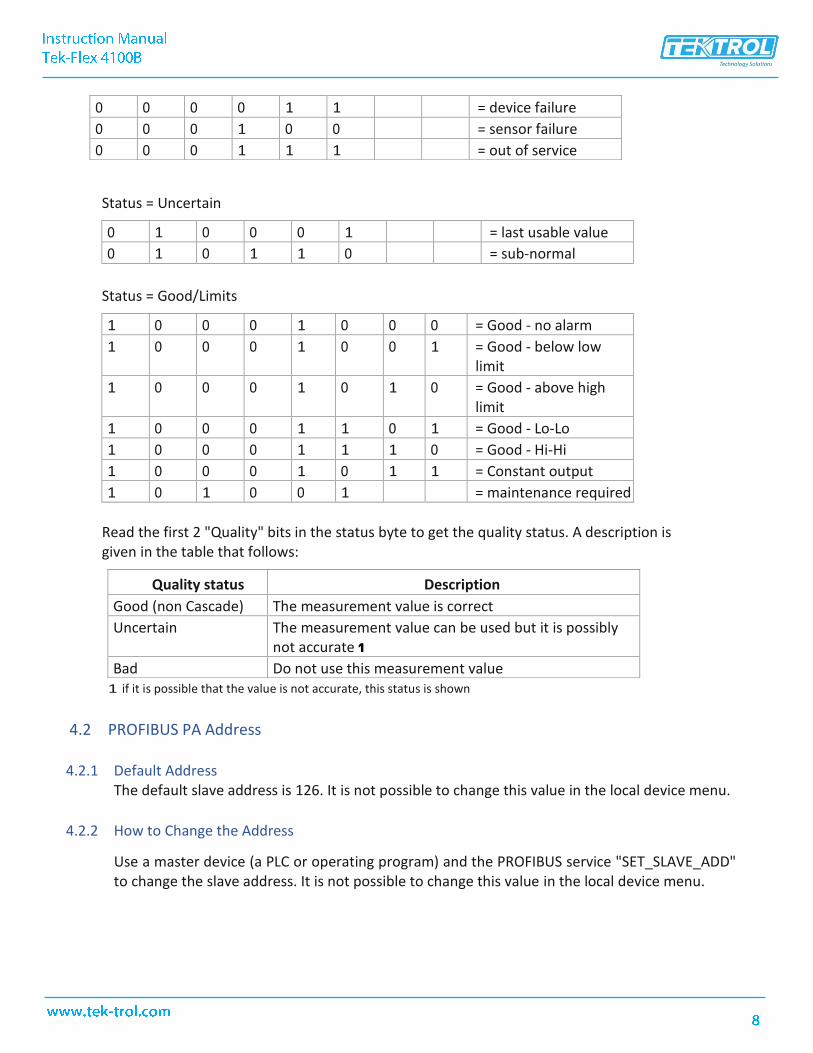
0 0 0 0 1 1 = device failure
0 0 0 1 0 0 = sensor failure
0 0 0 1 1 1 = out of service
Status = Uncertain
0 1 0 0 0 1 = last usable value
0 1 0 1 1 0 = sub-normal
Status = Good/Limits
1 0 0 0 1 0 0 0 = Good - no alarm
1 0 0 0 1 0 0 1 = Good - below low limit
1 0 0 0 1 0 1 0 = Good - above high limit
1 0 0 0 1 1 0 1 = Good - Lo-Lo
1 0 0 0 1 1 1 0 = Good - Hi-Hi
1 0 0 0 1 0 1 1 = Constant output
1 0 1 0 0 1 = maintenance required
Read the first 2 "Quality" bits in the status byte to get the quality status. A description is given in the table that follows:
Quality status Description
Good (non Cascade) The measurement value is correct
Uncertain The measurement value can be used but it is possibly not accurate 1
Bad Do not use this measurement value 1 if it is possible that the value is not accurate, this status is shown
4.2 PROFIBUS PA Address
4.2.1 Default Address The default slave address is 126. It is not possible to change this value in the local device menu.
4.2.2 How to Change the Address
Use a master device (a PLC or operating program) and the PROFIBUS service "SET_SLAVE_ADD" to change the slave address. It is not possible to change this value in the local device menu.

NOTE
If you use the PROFIBUS service "SET_SLAVE_ADD" to change the slave address and the "NO_ADD_CHG" flag has the value "true", the PROFIBUS service "SET_SLAVE_ADD" will not be available for subsequent changes.
If the PROFIBUS service "SET_SLAVE_ADD" is not available:
1 Use acyclic services "FACTORY_RESET" to reset the slave address. 2 Use the PROFIBUS service "SET_SLAVE_ADD" to change the slave address to the new value.
4.3 Error Handling
If the device finds an error, more data will be sent to the Master Communication Module. The description of this supplementary data is given in the GSD file. Refer to UNIT_DIAG_BIT(i).
4.4 Model Chart
Example Tek-Flex 4100B 1 1 1 XXXX Tek-Flex 4100B-1-1-1-XXX
Series Tek-Flex 4100B Two-Wire Loop-Powered OEM TDR Level Transmitter
Process Connection
1 2
¾" NPT
1½" NPT 3 1" NPT
Probe Type
1 2
Coaxial Probe (10' Max.) 2 mm Wire Probe (60' Max.)
3 4 mm Wire Probe (60' Max.)
Electrical Connection
1
Two ½" NPT
Probe Length XXXX Probe Length in Inches

TEKM
ATI
ON
LLC
rese
rves
the
right
to c
hang
e th
e de
sign
s an
d/or
mat
eria
ls o
f its
pro
duct
s w
ithou
t not
ice.
The
con
tent
s of
this
pub
licat
ion
are
the
prop
erty
of
TEK
MA
TIO
N a
nd c
anno
t be
repr
oduc
ed b
y an
y ot
her p
arty
with
out w
ritte
n pe
rmis
sion
. All
right
s re
serv
ed. C
opyr
ight
© 2
019
TEKM
ATI
ON
LLC
TEKM
ATI
ON
LLC
D
OC#
TEK/
MR/
MN
L/IM
-410
0B/0
319/
A
Tek-Trol LLC
www.tek-trol.com
Flow | Level | Temperature | Pressure | Valves | Analyzers | Accessories | TekValSys
796 Tek Drive Crystal Lake, IL 60014 USATel.: +1 847 857 6076 , +1 847 655 7428 Fax: +1 847 655 6147
Email: [email protected]
Tek-Trol is a fully owned subsidiary of TEKMATION LLC. We o�er our customers a comprehensive range of products and solutionsfor process, power and oil & gas industries. Tek-Trol provides process measurement and control products for Flow, Level,
Temperature & Pressure Measurement, Control Valves & Analyzer systems. We are present in 15 locations globally and are knownfor our knowledge, innovative solutions, reliable products and global presence.