technotes nf
TRANSCRIPT
NF-5
EMI/EMCFilter
Rated Voltage
Rated Current
Test Voltage (Withstand Voltage)
Insulation Resistance
Leakage Current
DC Resistance
Temperature/Humidity
Circuitry
Safety Standards
Attenuation Characteristic (Static Characteristic)
Pulse Attenuation Characteristic
Ground Capacitor Codes
Options
Noise Basics1
Selection of EMI Filters2
EMI Fi lter
1
2
3
4
5
6
7
8
9
10
11
12
13
Input and Output Impedance and Filter Circuit
EMI Filter Installation and Orientation
Combining Multiple EMI Filters
External Ferrite Core
1
2
3
4
What Is Noise?
Noise Sources
What Is EMC?
Propagation Paths of Noise
Basics of Noise Reduction
Types of Conductive Noise
Types of and Countermeasures for Noise
a. Conductive noise
b. Inductive noise
c. Radiated noise
a. High-frequency noise
b. Pulse noise
c. Surge noise
a. Single-phase one-stage filter
b. Single-phase two-stage filter
a. Overview of safety standards
b. Safety standards for EMI filters
c. CCC approval from China
a. DIN rail installation type
b. Terminal block type
c. High permeability choke coil type
d. Hexagon socket head cap bolt type
e.With switch of line to ground capacitor type
f.Improve differential mode attenuation type
g.Ultra high attenuation type for EU
1
2
3
4
5
6
7
How to Use EMI Filters3Ground Wiring
Input and Output Wiring
1
2
Supplement6Source Voltages in the World1
CE Marking
Conducted Emission
Radiated Emission
Power Supply Harmonic Current
Electrostatic Discharge
Radio frequency electromagnetic field
Fast Transient/Burst
Surge
Conducted Radio-frequency Interference
Power Frequency Magnetic Field
Voltage Dip/Momentary Power Interruption
Unit of Noise
Detection Method
Noise Terminal Voltages, Radiated Emission Limits (Extractions)
Terminology related to EMC Test
Noise Reduction4
EMC Test5
a. Peak detection
b. Quasi-peak detection
c. Average detection
a. Machinery directive
b. EMC directive
c. Low voltage directive
1
2
3
4
5
6
7
8
9
10
11
12
13
14
15
me_nf05-22.indd NF-5me_nf05-22.indd NF-5 2015/06/18 18:30:392015/06/18 18:30:39
NF-6
EMI/EMCFilter
What a designer expects (an ideal steady voltage source)
In reality, noises are included.
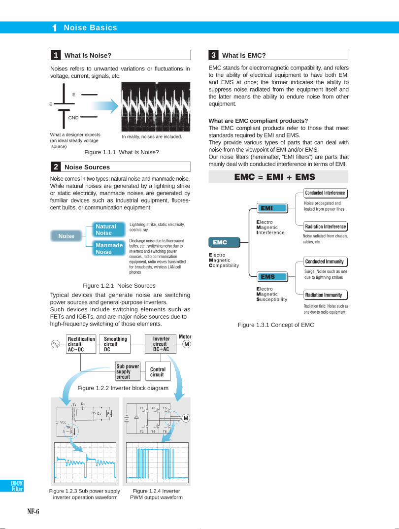
Noise comes in two types: natural noise and manmade noise. While natural noises are generated by a lightning strike or static electricity, manmade noises are generated by familiar devices such as industrial equipment, fluores-cent bulbs, or communication equipment.
EMC stands for electromagnetic compatibility, and refers to the ability of electrical equipment to have both EMI and EMS at once; the former indicates the ability to suppress noise radiated from the equipment itself and the latter means the ability to endure noise from other equipment.
What are EMC compliant products?The EMC compliant products refer to those that meet standards required by EMI and EMS.They provide various types of parts that can deal with noise from the viewpoint of EMI and/or EMS.Our noise filters (hereinafter, “EMI filters”) are parts that mainly deal with conducted interference in terms of EMI.
Typical devices that generate noise are switching power sources and general-purpose inverters.Such devices include switching elements such as FETs and IGBTs, and are major noise sources due to high-frequency switching of those elements.
Figure 1.1.1 What Is Noise?
What Is Noise?1 What Is EMC?3
Noise Sources2
Figure 1.2.1 Noise Sources
Noise
Natural Noise
Manmade Noise
Lightning strike, static electricity,cosmic ray
Discharge noise due to fluorescent bulbs, etc., switching noise due to inverters and switching power sources, radio communication equipment, radio waves transmitted for broadcasts, wireless LAN,cell phones
EMC
Conducted Interference
Radiation Interference
Conducted Immunity
Radiation Immunity
Figure 1.2.3 Sub power supply inverter operation waveform
EMC = EMI + EMS
Electro Magnetic Compatibility
Electro Magnetic Susceptibility
Electro Magnetic Interference
Noise propagated and leaked from power lines
Figure 1.3.1 Concept of EMC
Noise radiated from chassis, cables, etc.
Surge: Noise such as one due to lightning strikes
Radiation field: Noise such as one due to radio equipment
Figure 1.2.4 Inverter PWM output waveform
GND
E
E
T1
TR1
VCC
D1
C1 RL
M
T1 T3 T5
T2 T4 T6
Figure 1.2.2 Inverter block diagram
EMI
EMS
Noise Basics1
Rectification circuitAC DC
Smoothing circuitDC
Inverter circuitDC AC
Motor
Sub power supply circuit
Control circuit
M
Noises refers to unwanted variations or fluctuations in voltage, current, signals, etc.
me_nf05-22.indd NF-6me_nf05-22.indd NF-6 2015/06/18 18:30:402015/06/18 18:30:40

NF-7
EMI/EMCFilter
Noise Basics1
The propagation of noise consists of a noise source, an entity that is affected by the noise, and propaga-tion path that connects both. To reduce noise: Reduce the noise level of a noise source Make it more difficult for noise to propagate Make equipment less vulnerable to noise In addition to the abore, designs must consider standards, quality and cost of noise reduction methods.
Noise is divided into two types based on its genera-tion mode: normal mode noise and common mode noise. Normal mode noise is also called differential mode noise, and refers to noise generated between power lines. Common mode noise refers to noise generated between a power line and ground line.
a. Conductive noiseRefers to noise that propagates through a power line or PCB tracing.
b. Inductive noiseRefers to noise that is induced due to electromagnetic or electrostatic induction caused by a power line or a signal line of a peripheral device when it is placed near a line or pattern in which noise current flows and propagates through the line.
c. Radiated noiseNoise radiated by an antenna (or a line be having as an antenna) that propagates to other devices through the air.
Propagation Paths of Noise4
Basics of Noise Reduction5
a. High-frequency noiseAlso called EMI noise or power supply noise and refers to high-frequency components such as the clock frequency of a computer and switching frequency of power sources. As an antinoise measure, an EMI filter should be installed on the input side. An appropriate filter should be selected based on requirements such as attenuation, mechani-cal design and cost.
Types of and Countermeasures for Noise7
Types of Conductive Noise6
Figure 1.4.1 Propagation Paths of Noise
Figure 1.5.1 Overview of Noise Generation and Propagation Path
Load
Power supply
Other apparatus
Other apparatus
Other apparatus
Power electronics devices (inverters and switching power source)
Radiated noise
Inductive noise
Conductive noise
Figure 1.6.1 Noise Generation Paths (Example in which a noise source is within power equipment)
[Normal Mode] [Common Mode]
Kinds of Noise
a. High-frequency noise
b. Pulse noise
c. Surge noise
Input
Power source machine machine
Noise source
Input
Power source machine machine
Noise source
EMI Filter Motor driver Motor
LINE LOAD
Figure 1.7.1 Example of Noise Reduction by an EMI Filter
100
90
80
70
60
50
40
30
20
10
00.1 1 10 100
Leve
l [dB
µV]
Frequency [MHz]
EN55011 Group2 ClassA
AV
QP
No EMI Filter
With EMI Filter
Equipment affected by a noise failure
Propagation PathsNoise Sources
me_nf05-22.indd NF-7me_nf05-22.indd NF-7 2015/06/18 18:30:402015/06/18 18:30:40
NF-8
EMI/EMCFilter
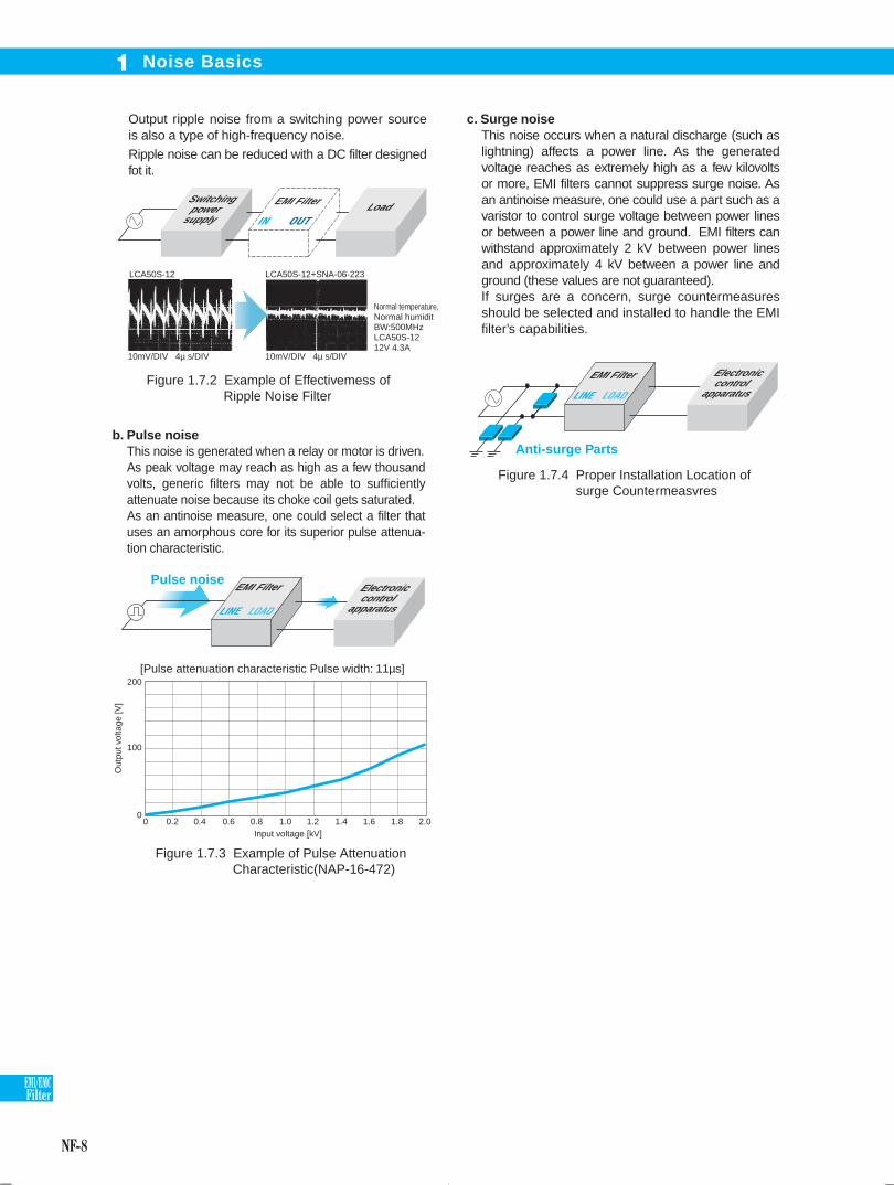
b. Pulse noiseThis noise is generated when a relay or motor is driven.As peak voltage may reach as high as a few thousand volts, generic filters may not be able to sufficiently attenuate noise because its choke coil gets saturated. As an antinoise measure, one could select a filter that uses an amorphous core for its superior pulse attenua-tion characteristic.
c. Surge noiseThis noise occurs when a natural discharge (such as lightning) affects a power line. As the generated voltage reaches as extremely high as a few kilovolts or more, EMI filters cannot suppress surge noise. As an antinoise measure, one could use a part such as a varistor to control surge voltage between power lines or between a power line and ground. EMI filters can withstand approximately 2 kV between power lines and approximately 4 kV between a power line and ground (these values are not guaranteed). If surges are a concern, surge countermeasures should be selected and installed to handle the EMI filter’s capabilities.
Figure 1.7.3 Example of Pulse Attenuation Characteristic(NAP-16-472)
Noise Basics 1
Figure 1.7.4 Proper Installation Location of surge Countermeasvres
200
100
0
Out
put v
olta
ge [V
]
Input voltage [kV]
[Pulse attenuation characteristic Pulse width: 11µs]
0 0.2 0.4 0.6 0.8 1.0 1.2 1.4 1.6 1.8 2.0
Anti-surge Parts
EMI Filter
EMI Filter Pulse noise
LINE LOAD
LINE LOAD
Output ripple noise from a switching power source is also a type of high-frequency noise. Ripple noise can be reduced with a DC filter designed fot it.
EMI Filter Switching power
supplyLoad
Figure 1.7.2 Example of Effectivemess of Ripple Noise Filter
10mV/DIV 4µ s/DIV 10mV/DIV 4µ s/DIV
Normal temperature, Normal humiditBW:500MHzLCA50S-1212V 4.3A
LCA50S-12 LCA50S-12+SNA-06-223
IN OUT
Electronic control
apparatus
Electronic control
apparatus
me_nf05-22.indd NF-8me_nf05-22.indd NF-8 2015/06/18 18:30:412015/06/18 18:30:41

NF-9
EMI/EMCFilter
This example indicates that when the maximum ambient temperature reaches 75 , the EMI filter should be used with a load factor of approximately 60% (approximately 60% of the rated current) or lower.Current higher than the rated current would be allowed to flow in EMI filters for a short period of time only. Inrush current (single shots with a length of a few milliseconds) from devices such as a general switching power source does not cause any problems, but relatively long and / or repetitive peak current draws can result in the average current exceeding the filter’s raring.
The rated current is the maximum load current (nominal value) that can be continuously carried. If the ambient temperature is high, however, the load current needs to be derated.Figure 2.2.1 shows an example of a derating charac-teristic.
The rated voltage is the maximum line voltage (nominal value) allowable to be used.As the rated voltages for some parts used within an EMI filter are high in reality, however, voltages higher than the rated voltage of the EMI filter may be used without causing any trouble.In fact, the rated voltages of filter components are often higher, in which case the filter can handle actual voltages that exceed its ratins.In the case of some EMI filters, the maximum opera-tion voltages are defined by specifications for them, separately from rated voltages.Note that using EMI filters at voltages lower than their rated voltages do not pose any problems. For example, an EMI filter with a rated voltage of AC 250 V can be used for power lines of AC 100V.
As for line frequency, EMI filters for AC power supply lines have been basically designed to be used with the commercial frequency (50 Hz/60 Hz).Higher frequencies such as 400Hz can cause problems such as excessive capacitor heating.Note that EMI filters for AC power lines can also be used for DC power supply lines.
The test voltage is a voltage value that is applied at the time of withstand voltage test. The withstand voltage test is to verify that the part does not break when applying a high voltage in a short period of time between a terminal (line) and the mounting plate (ground) of an EMI filter.In the case of EMI filters for AC power lines, the test voltage is generally AC 2000 V or AC 2500 V.
In withstand voltage tests, the high voltage applied between a line and ground, results in abnormally high leakage current flow. When carrying out a withstand voltage test in an acceptance inspection, please set the cutoff current of withstand voltage test equipment to an appropriate value (the cutoff current defined in the specifications for the EMI filter).For some EMI filters that have ground capacitors with extremely large capacity, DC voltages may be used for test voltages because the leakage current becomes too high when AC voltages are applied.
Rated Voltage1 Test Voltage (Withstand Voltage)3
Insulation resistance is a resistance value when apply-ing a specified DC voltage (normally 500 V) between isolated conductors such as a terminal (line) and the mounting plate (ground), and regarded as one indicator of degree of insulation. The insulation resistance is found by measuring the very small current that flows in an insulating material such as a resin case and capacitor when DC voltage is applied.
Insulation Resistance4
The leakage current is an electric current that flows from the ground terminal of an EMI filter when the filter is connected to an AC power line.Generally, as one sets the capacitance of a ground capacitor to a higher value, the reduction effect on common mode noise will be heightened and at the same time, the leakage current will increase. Care must be taken, because large leakage current could cause a circuit breaker to trip or electric shock to occur when the EMI filter is not properly grounded.
Current ( ) that flows from each power line to ground is represented with the following expression; it forms the basis of leakage current calculation.
Leakage Current5
Rated Current2
Figure 2.2.1 Derating Curve
Selection of EMI Filters2
100
80
60
40
20
0-40 -30 -20 40 50 55 60 70 80 90
Load
fact
or[%
]
Ambient air temperature[ ]
f : Power frequencyC : Capacitance between line
and ground E : Power supply voltage
between line and ground
me_nf05-22.indd NF-9me_nf05-22.indd NF-9 2015/06/18 18:30:412015/06/18 18:30:41

NF-10
EMI/EMCFilter
Temperature/Humidity7
DC Resistance6 Circuitry8
Selection of EMI Filters2
a. Single-phase 1-stage filter
Figure 2.8.1 Circuit Structure Example of a Single-phase 1-stage EMI Filter
Figure 2.8.2 Circuit Structure Example of a Single-phase 2-stage EMI filter
b. Single-phase 2-stage EMI filter
Figure 2.8.3 Example of Comparing Attenuation Characteristics between 1-stage and 2-stage EMI filters.
0
10
20
30
40
50
60
70
80
90
100
11000.1 0.1 101 100
Atte
nuat
ion
[dB
]
Frequency [MHz]
NBC-06-4722-stage
NAC-06-4721-stage
1
2 4
3CY
CXCXRCY
LOADLINE
Case
L
1
2 4
3CY
CXCXR
CY
LOADLINE
Case
L L
The following represents examples of EMI filter circuit structures.
DC resistance is a resistance value between the input and output of an EMI filter (the sum of resistance values for both directions).It is mostly accounted for with the coil resistances but also includes connections between the coils and terminals.The voltage drop caused by an EMI filter is represented with the following expression:
This figure shows a standard circuit structure for single-phase EMI filters.L and CYs reduce the common mode noise; CXs and leakage inductance from L reduce the normal mode noise.R indicates a discharge resistance for capacitors.
The above figure represents a circuit structure example of placing choke coils in two stages to improve the attenuation characteristic. The following graph shows an example comparison of attenuation characteristics for a 1-stage and 2-stage EMI filter.
a. Operating temperatureThis is the range of ambient temperatures for which the product’s usage is guaranteed.If an ambient temperature is high, the load current needs to be derated.
b. Operating humidityThis is the range of ambient humidities for which the product’s usage is guaranteed. It assumes no condensation.
c. Storage temperature and humidityThe specified ranges of ambient temperatures and humidities that EMI filters in an unenergized state can be stored without deteriorating performance. No condensation is assumed for the storage humidity.
[Common Mode]
Note that specifications for some products define voltage drops when rated current is carried, instead of resistance values.
Voltage drop = DC resistance x Load current
me_nf05-22.indd NF-10me_nf05-22.indd NF-10 2015/06/18 18:30:422015/06/18 18:30:42

NF-11
EMI/EMCFilter
a. General description of safety standardsThe international standards consist of IEC standards which concern the electrical fields, and ISO standards which concern the non-electrical fields.
� IEC (International Electrotechnical Commission)Standardization organization for standards related to the electrical fields; its headquarters is located in Switzerland. It releases technical standards for electricity based on the latest sciences and technologies, and each country develops its own specific safety standards based on the corresponding IEC standards.
� CISPR(Comite International Special des
Perturbations Radioelectriques
=International Special Committee
on Radio Interference)One of IEC’s special committees; it was established with the aim to integrate standards such as allowable values and measurement methods for interfering waves causing radio communication failures, and includes a standardization committee for EMC (Electro Magnetic Compatibility).
� European Standard / EN Standard(Europaische Norm=European Standard)The EN Standard was created based on the IEC and CISPR standards, and consists of items almost similar to those in both standards.A unique number is assigned to each standard.(Exampla:IEC939 EN60939)
c. CCC approval from ChinaEMI filters do not fall within the scope of CCC.(as of November 2011)
� North AmericaUL (Underwriters Laboratories Inc.)A test organization established in 1894 by the Electrical Bureau of the National Board of Fire Underwriters. Since then, it has been performing compliance tests on various electric products.
CSA (Canadian Standard Association)A non-profit standardization organization established in Canada in 1919. Each state law in Canada requires that electric equipment that needs to be connected to a public power source conforms to the CSA standards.
As the US and Canada have signed MRA (Mutual Recognition Agreement), mutual approval can be obtained. If UL verifies that a certain electric product conforms to the CSA standard, or to the UL and CAS standards, the product is authorized to bear the following approval marks:
Safety Standards9
VDE
TUV
DEMKO
SEMKO
Germany
Germany
Denmark
Sweden
Europe standard sign
Sequence number
Standard classification number
[An example of Certification Authorities in Europe based on EN Standard]
Standard classification number
EN50000 series
EN55000 series
EN60000 series
Reference standards
General European standards
CISPR standards
IEC standards
Different products may conform to different safety standards and bear different approval marks (for use in different countries). Check the approved safety standards when considering purchasing them.
b. Safety standards for EMI filters
IEC939
EN60939
UL1283
C22.2 No.8
International standard
EU
USA
Canada
IEC
EN
UL
CSA
UL
CSA
USA
Canada
EN Standard:
CSA
UL,CSA
� ENEC (European Norm Electrical Certification)The safety approval mark in Europe that enables products to smoothly be delivered among all the EU signatories, EFTA (European Free Trade Area), and East European countries.Electronic products that are authorized to bear the ENEC mark do not need to be subjected to application procedures among the signatories. It provides a benefit of eliminating the need to obtain approval from each signatory to which they are distributed.The ENEC mark is intended to apply to products such as lighting equipment, transformers, information processing equipment, switches and EMI filters.
EU signatories…Germany, UK, Italy, Denmark, and 24 other countries EFTA……… Iceland, Norway, Switzerland, and Lichtenstein East European…Ukraine, Estonia, Belorussia, countries Moldova, Latvia, and Lithuania
Selection of EMI Filters2
me_nf05-22.indd NF-11me_nf05-22.indd NF-11 2015/06/18 18:30:422015/06/18 18:30:42
NF-12
EMI/EMCFilter
000
221
471
102
222
472
Attenuation Characteristic (Static Characteristic)10
Selection of EMI Filters2
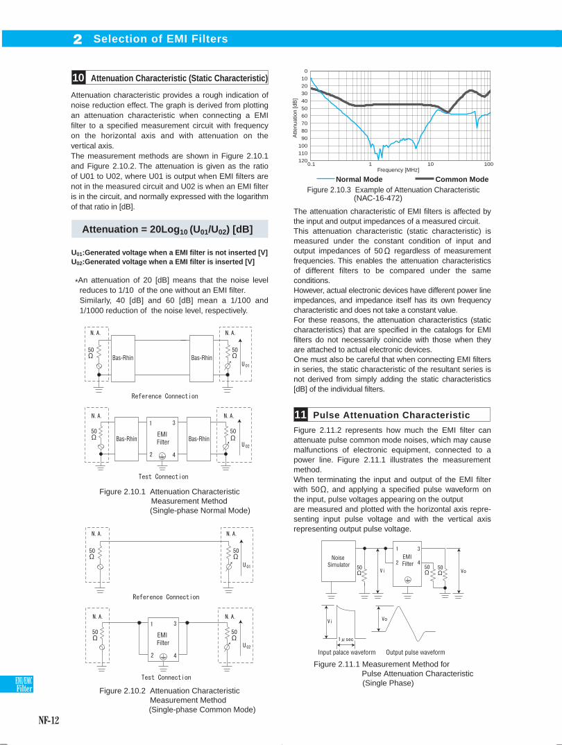
Attenuation characteristic provides a rough indication of noise reduction effect. The graph is derived from plotting an attenuation characteristic when connecting a EMI filter to a specified measurement circuit with frequency on the horizontal axis and with attenuation on the vertical axis.The measurement methods are shown in Figure 2.10.1 and Figure 2.10.2. The attenuation is given as the ratio of U01 to U02, where U01 is output when EMI filters are not in the measured circuit and U02 is when an EMI filter is in the circuit, and normally expressed with the logarithm of that ratio in [dB].
Pulse Attenuation Characteristic11
U01:Generated voltage when a EMI filter is not inserted [V]U02:Generated voltage when a EMI filter is inserted [V]
Attenuation = 20Log10 (U01/U02) [dB]
Figure 2.10.1 Attenuation Characteristic Measurement Method
(Single-phase Normal Mode)
Figure 2.10.2 Attenuation Characteristic Measurement Method
(Single-phase Common Mode)
*An attenuation of 20 [dB] means that the noise level reduces to 1/10 of the one without an EMI filter.Similarly, 40 [dB] and 60 [dB] mean a 1/100 and 1/1000 reduction of the noise level, respectively.
Figure 2.10.3 Example of Attenuation Characteristic (NAC-16-472)
Normal Mode Common Mode
0
10
20
30
40
50
60
70
80
90
100
110
1200.1 1 10 100
Atte
nuat
ion
[dB
]
Frequency [MHz]
Figure 2.11.1 Measurement Method for Pulse Attenuation Characteristic
(Single Phase)
EMI Filter
EMI Filter
EMI Filter
Bas-Rhin Bas-Rhin
Bas-Rhin Bas-Rhin
The attenuation characteristic of EMI filters is affected by the input and output impedances of a measured circuit.This attenuation characteristic (static characteristic) is measured under the constant condition of input and output impedances of 50 regardless of measurement frequencies. This enables the attenuation characteristics of different filters to be compared under the same conditions.However, actual electronic devices have different power line impedances, and impedance itself has its own frequency characteristic and does not take a constant value.For these reasons, the attenuation characteristics (static characteristics) that are specified in the catalogs for EMI filters do not necessarily coincide with those when they are attached to actual electronic devices.One must also be careful that when connecting EMI filters in series, the static characteristic of the resultant series is not derived from simply adding the static characteristics [dB] of the individual filters.
Figure 2.11.2 represents how much the EMI filter can attenuate pulse common mode noises, which may cause malfunctions of electronic equipment, connected to a power line. Figure 2.11.1 illustrates the measurement method.When terminating the input and output of the EMI filter with 50 , and applying a specified pulse waveform on the input, pulse voltages appearing on the output are measured and plotted with the horizontal axis repre-senting input pulse voltage and with the vertical axis representing output pulse voltage.
Noise Simulator
Input palace waveform Output pulse waveform
me_nf05-22.indd NF-12me_nf05-22.indd NF-12 2015/06/18 18:30:432015/06/18 18:30:43
NF-13
EMI/EMCFilter
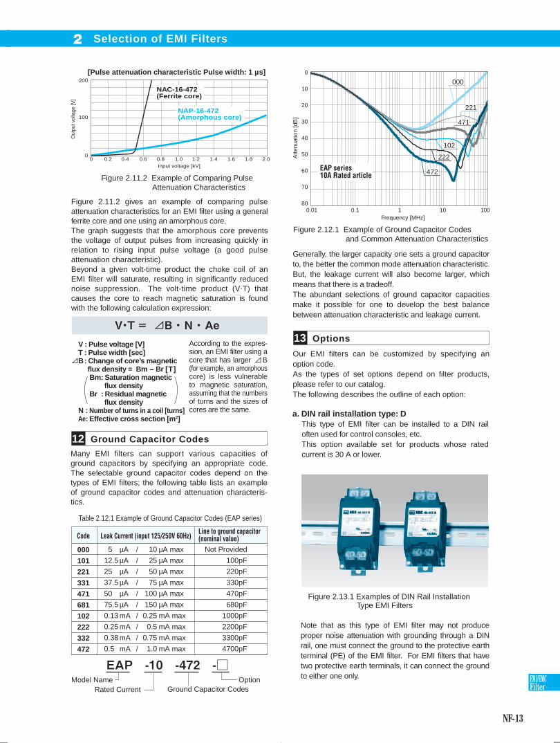
Ground Capacitor Codes12
Options13
Many EMI filters can support various capacities of ground capacitors by specifying an appropriate code. The selectable ground capacitor codes depend on the types of EMI filters; the following table lists an example of ground capacitor codes and attenuation characteris-tics.
Figure 2.11.2 gives an example of comparing pulse attenuation characteristics for an EMI filter using a general ferrite core and one using an amorphous core.The graph suggests that the amorphous core prevents the voltage of output pulses from increasing quickly in relation to rising input pulse voltage (a good pulse attenuation characteristic). Beyond a given volt-time product the choke coil of an EMI filter will saturate, resulting in significantly reduced noise suppression. The volt-time product (V.T) that causes the core to reach magnetic saturation is found with the following calculation expression:
Generally, the larger capacity one sets a ground capacitor to, the better the common mode attenuation characteristic. But, the leakage current will also become larger, which means that there is a tradeoff.The abundant selections of ground capacitor capacities make it possible for one to develop the best balance between attenuation characteristic and leakage current.
Figure 2.11.2 Example of Comparing Pulse Attenuation Characteristics
200
100
0
Out
put v
olta
ge [V
]
Input voltage [kV]
[Pulse attenuation characteristic Pulse width: 1 µs]
0 0.2 0.4 0.6 0.8 1.0 1.2 1.4 1.6 1.8 2.0
NAP-16-472(Amorphous core)
NAC-16-472(Ferrite core)
Table 2.12.1 Example of Ground Capacitor Codes (EAP series)
000
101
221
331
471
681
102
222
332
472
Leak Current (input 125/250V 60Hz)Line to ground capacitor(nominal value)
5
12.5
25
37.5
50
75.5
0.13
0.25
0.38
0.5
10
25
50
75
100
150
0.25
0.5
0.75
1.0
/
/
/
/
/
/
/
/
/
/
µA
µA
µA
µA
µA
µA
mA
mA
mA
mA
µA max
µA max
µA max
µA max
µA max
µA max
mA max
mA max
mA max
mA max
Not Provided
100pF
220pF
330pF
470pF
680pF
1000pF
2200pF
3300pF
4700pF
Model NameRated Current Ground Capacitor Codes
Option
Figure 2.12.1 Example of Ground Capacitor Codes and Common Attenuation Characteristics
a. DIN rail installation type: DThis type of EMI filter can be installed to a DIN rail often used for control consoles, etc.This option available set for products whose rated current is 30 A or lower.
Our EMI filters can be customized by specifying an option code.As the types of set options depend on filter products, please refer to our catalog. The following describes the outline of each option:
Note that as this type of EMI filter may not produce proper noise attenuation with grounding through a DIN rail, one must connect the ground to the protective earth terminal (PE) of the EMI filter. For EMI filters that have two protective earth terminals, it can connect the ground to either one only.
Figure 2.13.1 Examples of DIN Rail Installation Type EMI Filters
0
10
20
30
40
50
60
70
800.01 0.1 1 10 100
00000000
22221221
47471471
10102102
22222222
47472472
Atte
nuat
ion
[dB
]
Frequency [MHz]
EAP series10A Rated article
Selection of EMI Filters2
According to the expres-sion, an EMI filter using a core that has larger B (for example, an amorphous core) is less vulnerable to magnetic saturation, assuming that the numbers of turns and the sizes of cores are the same.
V : Pulse voltage [V]T : Pulse width [sec]B: Change of core’s magnetic flux density = Bm - Br [T] Bm: Saturation magnetic flux density Br : Residual magnetic flux densityN : Number of turns in a coil [turns]Ae: Effective cross section [m2]
Code
me_nf05-22.indd NF-13me_nf05-22.indd NF-13 2015/06/18 18:30:452015/06/18 18:30:45
NF-14
EMI/EMCFilter
Option code is possible combination.Please contact us for more information.
Selection of EMI Filters2
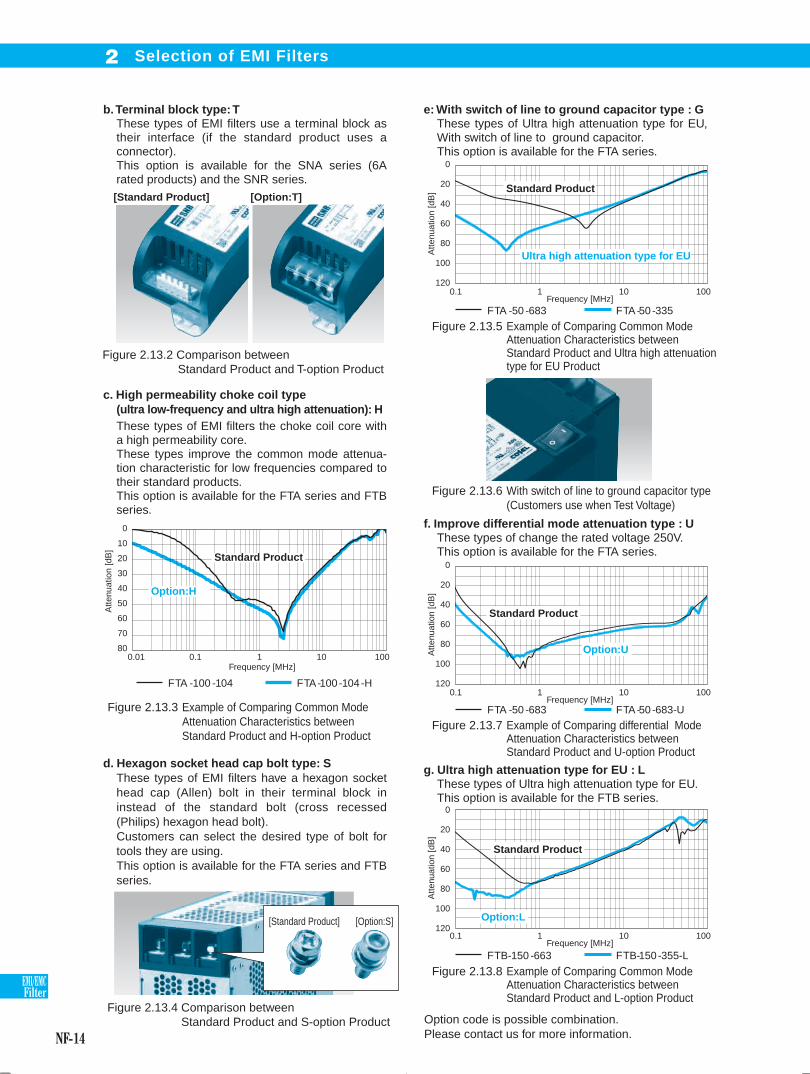
b. Terminal block type: TThese types of EMI filters use a terminal block as their interface (if the standard product uses a connector).This option is available for the SNA series (6A rated products) and the SNR series.
e: With switch of line to ground capacitor type : GThese types of Ultra high attenuation type for EU, With switch of line to ground capacitor.This option is available for the FTA series.
f. Improve differential mode attenuation type : UThese types of change the rated voltage 250V.This option is available for the FTA series.
g. Ultra high attenuation type for EU : LThese types of Ultra high attenuation type for EU.This option is available for the FTB series.
d. Hexagon socket head cap bolt type: SThese types of EMI filters have a hexagon socket head cap (Allen) bolt in their terminal block in instead of the standard bolt (cross recessed (Philips) hexagon head bolt).Customers can select the desired type of bolt for tools they are using.This option is available for the FTA series and FTB series.
c. High permeability choke coil type(ultra low-frequency and ultra high attenuation): HThese types of EMI filters the choke coil core with a high permeability core.These types improve the common mode attenua-tion characteristic for low frequencies compared to their standard products.This option is available for the FTA series and FTB series.
[Standard Product] [Option:T]
Figure 2.13.2 Comparison between Standard Product and T-option Product
FTA -100 -104 FTA-100-104-H
FTA -50 -683 FTA-50-335
FTA -50 -683 FTA-50-683-U
FTB-150 -663 FTB-150-355-L
Figure 2.13.4 Comparison between Standard Product and S-option Product
0.1 1 10 100
0
20
40
60
80
100
120
Atte
nuat
ion
[dB
]
Frequency [MHz]
0.1 1 10 100
0
20
40
60
80
100
120
Atte
nuat
ion
[dB
]
Frequency [MHz]
0.1 1 10 100
0
20
40
60
80
100
120
Atte
nuat
ion
[dB
]
Frequency [MHz]
Standard Product
Option:L
Standard Product
Option:U
Standard Product
Ultra high attenuation type for EU
[Standard Product] [Option:S]
0.10.01 1 10 100
Standard Product
Option:H
0
10
20
30
40
50
60
70
80
Atte
nuat
ion
[dB
]
Frequency [MHz]
Figure 2.13.5 Example of Comparing Common ModeAttenuation Characteristics between Standard Product and Ultra high attenuation type for EU Product
Figure 2.13.7 Example of Comparing differential ModeAttenuation Characteristics between Standard Product and U-option Product
Figure 2.13.8 Example of Comparing Common ModeAttenuation Characteristics between Standard Product and L-option Product
Figure 2.13.6 With switch of line to ground capacitor type(Customers use when Test Voltage)
Figure 2.13.3 Example of Comparing Common Mode Attenuation Characteristics between Standard Product and H-option Product
me_nf05-22.indd NF-14me_nf05-22.indd NF-14 2015/06/18 18:30:462015/06/18 18:30:46
NF-15
EMI/EMCFilter
How to Use EMI Filters3
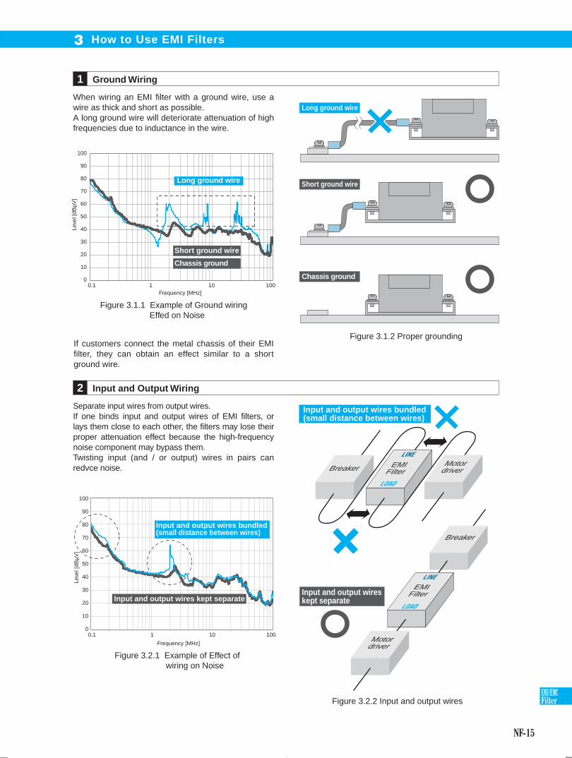
When wiring an EMI filter with a ground wire, use a wire as thick and short as possible.A long ground wire will deteriorate attenuation of high frequencies due to inductance in the wire.
Ground Wiring1
Separate input wires from output wires. If one binds input and output wires of EMI filters, or lays them close to each other, the filters may lose their proper attenuation effect because the high-frequency noise component may bypass them.Twisting input (and / or output) wires in pairs can redvce noise.
Input and Output Wiring2
0.1 1 10 100
100
90
80
70
60
50
40
30
20
10
0
Leve
l [dB
µV]
Frequency [MHz]
Long ground wire
Short ground wire
Chassis ground
Figure 3.1.1 Example of Ground wiring Effed on Noise
Long ground wire
Short ground wire
Chassis ground
If customers connect the metal chassis of their EMI filter, they can obtain an effect similar to a short ground wire.
Figure 3.1.2 Proper grounding
0.1 1 10 100
100
90
80
70
60
50
40
30
20
10
0
Leve
l [dB
µV]
Frequency [MHz]
Input and output wires bundled (small distance between wires)
Input and output wires kept separate
Breaker
EMI Filter
Motor driver
Input and output wires kept separate
Input and output wires bundled (small distance between wires)
Breaker EMI Filter
Motor driver
Figure 3.2.1 Example of Effect of wiring on Noise
Figure 3.2.2 Input and output wires
LINE
LOAD
LINE
LOAD
me_nf05-22.indd NF-15me_nf05-22.indd NF-15 2015/06/18 18:30:572015/06/18 18:30:57

NF-16
EMI/EMCFilter
With no core
The LINE side core insertion
The LOAD side core insertion
Noise Reduction4
The input/output impedances of a noise source and a load will have various optimal filter circuits. General EMI filters take a configuration of a low pass filter that combines L and C. If the expected attenuation effect can not be obtained, impedances of noise source and load may be the reasons.
Generally, an EMI filter is placed in a way that the LINE terminal is connected to the input side, but it can also be used in a reverse configuration.However, it may end up producing a different attenuation effect.
If the internal circuit consists of a symmetric EMI filter (one of the NBC series or TBC series), the direction in which the filter is connected will not cause any difference in noise attenuation. But in the case of asymmetric ones, it may cause difference in the attenuation.
Input and Output Impedance and Filter Circuit1
EMI Filter Installation and Orientation2
Zi: Input impedance (impedance of noise source)
Zo: Output impedance (impedance of load)
EMIFilterNoise source
Figure 4.1.1 Input/output Impedances of an EMI Filter Circuit
0.1 1 10 100
100
90
80
70
60
50
40
30
20
10
0
Leve
l [dB
µV]
Frequency [MHz]
Figure 4.2.2 Example of Effed of Filter Orientation on Noise
EMIFilter
TAC-30
Motordriver Motor
Motor
M
EMIFilter
TAC-30
Motordriver
M
Connection
Connection
Figure 4.2.1 Direction in which an EMI Filter Is Attached and Connected
Case
LINE LOAD
1
2
3
4
CYCY
5
6
LINE
Case
LOAD
1
2
3
CYCY
4
5
6
CY: Line to ground capacitor: Mounting Plate
Figure 4.2.3 TAC Series Circuit Diagram (Circuit Is Asymmetric)
Figure 4.2.4 TBC Series Circuit Diagram (Circuit Is Symmetric)
High
Hig
h
Inpu
t im
peda
nce
Low
LowOutput impedance
Table 4.1.1 Combinations of I/O Impedances and Optimal Filters
(Zi)
LINE LOAD
LINELOAD
Connection
Connection
(Zo)
me_nf05-22.indd NF-16me_nf05-22.indd NF-16 2015/06/18 18:31:022015/06/18 18:31:02
NF-17
EMI/EMCFilter
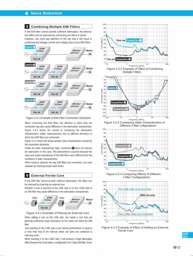
If one EMI filter cannot provide sufficient attenuation, the effect can be improved by inserting an external core.Whether a core is inserted on the LINE side or on the LOAD side of an EMI filter may cause difference in the attenuation characteristic.
Combining Multiple EMI Filters3
External Ferrite Core4
EMIFilter
TAC-30
Motordriver
Figure 4.3.1 Example of EMI Filter Connection Directions
EMIFilter
TAC-30
EMIFilter
TAC-30
Motordriver
EMIFilter
TAC-30
EMIFilter
TAC-30
Motordriver
EMIFilter
TAC-30
EMIFilter
TAC-30
Motordriver
0.01 0.1 1 10 100
0
10
20
30
40
50
60
70
80
90
100
110
120
Att
enu
atio
n [
dB
]
Figure 4.3.3 Comparing Static Characteristics of Different 2-filter cofigurations
Figure 4.3.2 Example of Effect of Combining Multiple Filters
0.1 1 10 100
100
90
80
70
60
50
40
30
20
10
0
Lev
el [
dB
µV
]L
eve
l [d
Bµ
V]
Lev
el [
dB
µV
]
Frequency [MHz]
Frequency [MHz]
Frequency [MHz]
Frequency [MHz]
Two set
One set
0.1 1 10 100
100
90
80
70
60
50
40
30
20
10
0
Figure 4.3.4 Comparing Effects of Different 2-filter Configurations
0.1 1 10 100
100
90
80
70
60
50
40
30
20
10
0
With no coreWith no coreWith no core
The LINE side core insertionThe LINE side core insertionThe LINE side core insertion
The LOAD side core insertionThe LOAD side core insertionThe LOAD side core insertion
Figure 4.4.2 Example of Effect of Adding an ExternalFerrite Core
When adding a core on the LINE side, one needs a core that can generate sufficiently large inductance for the choke coil within the EMI filter. Just inserting on the LINE side a core whose performance is equal to or less than that of the internal choke coil does not contribute to reducing noise.When inserting it on the LOAD side, it will produce a large attenuation effect because the circuit takes a configuration of a T-type EMI filter circuit.
EMIFilter
TAC-30
Motordriver
CoreCore
Figure 4.4.1 Example of Placing an External Core
LINE LOAD
LINE LOAD
LINELOAD LINELOAD
LINELOADLINE LOAD
LINE LOAD
LINE LOAD
Noise Reduction4
If one EMI filter cannot provide sufficient attenuation, the attenua-tion effect can be improved by connecting two filters in series. However, one must pay attention to the fact that it will result in combining the leakage current and voltage drop of two EMI filters.
When connecting two EMI filters, the direction in which they are connected may also cause difference in the attenuation characteristic.Figure 4.3.3 shows the results of comparing the attenuation characteristics (static characteristics) due to different directions in which two EMI filters are connected.Figure 4.3.4 shows the actual sample noise characteristics caused by the connection directions.Unlike the static characteristic data, connection does not improve the attenuation in this case. This phenomenon occurred because the input and output impedances of the EMI filters were different from the conditions of static characteristics.When trying to optimize the way EMI filters are connected, one must evaluate by checking actual noise levels.
Connection
Connection
Connection
Connection
Motor
M
Motor
M
Motor
M
Motor
M
Motor
M
Connection
Connection
Connection
Connection
Connection
Connection
Connection
Connection
me_nf05-22.indd NF-17me_nf05-22.indd NF-17 2015/06/18 18:31:032015/06/18 18:31:03

NF-18
EMI/EMCFilter
0.8[m]
EUT
EMC Test5
For machines and electric products to be sold in the EU area, manufacturers are required to bear a CE mark to prove they are in compliance with safety requirements, quality control, and ecocide prevention. To be allowed to do so, they must meet appropriate EC directives. The following describes the EC directives that are applied to general machinery products:
CE Marking1 Radiated Emission3
The voltages of interfering waves propagated through a power cable from equipment to the outside are measured with LISN in an open site or anechoic chamber .
When operating equipment, the strength of electromagnetic waves is measured in a range of specified frequencies at a location 3 or 10 m away from the equipment
Conducted Emission2
a. Machinery directiveThis directive covers products that are an assembly of parts and have a driving section (with the central focus on industrial equipment).
b. EMC directiveThis directive is intended to apply to electric parts which can be sources of radio disturbance or are affected by electromagnetic interference. It requires that two items, emission (EMI) and immunity (EMS), be met.
c. Low voltage directiveThis directive is intended to apply to products that operate with a rated voltage in the range of 50 to 1000 V AC or 75 to 1500 V DC.
As there are no appropriate EC directives (including the ones described above) which apply to EMI filters, EMI filter products cannot bear a CE mark.
However, EMI filters can obtain an ENEC mark, which has a similar effect on bypassing application procedures of its signatories.
EN61000-6-4
0.8[m]0.4[m]
0.8[m]
EUT
LISN Powersupply
Figure 5.2.1 Example of Conducted Emissions Measurement Configuration
: Refer to the description in “Terminology related to EMC Test” in this document.
EN61000-6-4
Power Supply Harmonic Current4
One analyzes the frequencies of input currents and checks the value of the harmonic current for each order.
EN61000-3-2
Electrostatic Discharge5
This test simulates effects of electrostatic discharge (malfunctions or destruction of semiconductor elements) and includes contact discharge and aerial discharge in its scope.
EN61000-4-2
Figure 5.3.1 Example of Radiated Emission Measurement Configuration
100%90%
10%
at30ns
at60ns
t
Ipeak
30ns60nstr=0.7 to 1ns
Figure 5.5.1 Discharge current waveform
Table 5.5.1 Application Level
LevelSpecifiedvoltage
First peakdischarge current
Rise time
Current valueat 30 ns
Current valueat 60 ns
2kV
4kV
6kV
8kV
1
2
3
4
7.5A
15A
22.5A
30A
2A
4A
6A
8A
4A
8A
12A
16A
0.7 - 1ns
0.7 - 1ns
0.7 - 1ns
0.7 - 1ns
3[m] or 10[m]Turntable
Antenna
1 - 4[m]
me_nf05-22.indd NF-18me_nf05-22.indd NF-18 2015/06/18 18:31:032015/06/18 18:31:03
NF-19
EMI/EMCFilter
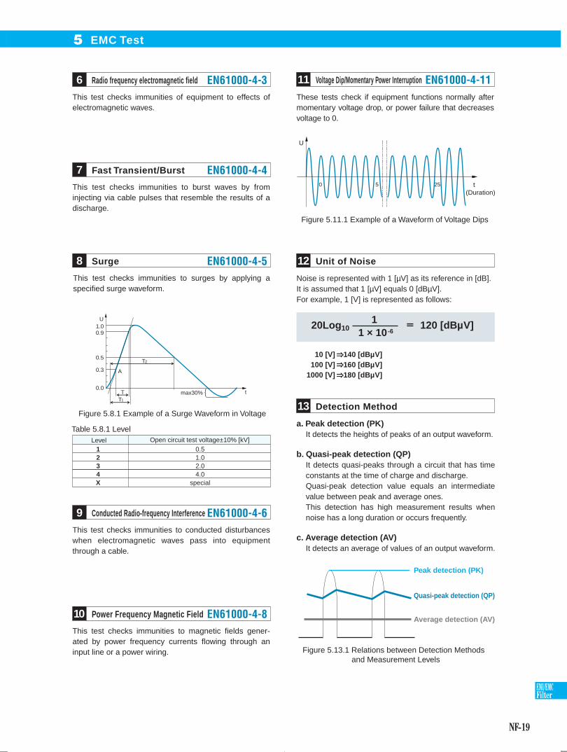
This test checks immunities of equipment to effects of electromagnetic waves.
These tests check if equipment functions normally after momentary voltage drop, or power failure that decreases voltage to 0.
Noise is represented with 1 [µV] as its reference in [dB].It is assumed that 1 [µV] equals 0 [dBµV].For example, 1 [V] is represented as follows:
This test checks immunities to burst waves by from injecting via cable pulses that resemble the results of a discharge.
This test checks immunities to surges by applying a specified surge waveform.
This test checks immunities to conducted disturbances when electromagnetic waves pass into equipment through a cable.
This test checks immunities to magnetic fields gener-ated by power frequency currents flowing through an input line or a power wiring.
1.00.9
0.5
0.3
0.0t
U
T2
T1
T
A
max30%
Figure 5.8.1 Example of a Surge Waveform in Voltage
Level Open circuit test voltage±10% [kV]1234X
0.51.02.04.0
special
Table 5.8.1 Level
0 5
U
25 t(Duration)
Figure 5.11.1 Example of a Waveform of Voltage Dips
10 [V] 140 [dBµV]100 [V] 160 [dBµV]
1000 [V] 180 [dBµV]
a. Peak detection (PK)It detects the heights of peaks of an output waveform.
b. Quasi-peak detection (QP)It detects quasi-peaks through a circuit that has time constants at the time of charge and discharge.Quasi-peak detection value equals an intermediate value between peak and average ones.This detection has high measurement results when noise has a long duration or occurs frequently.
c. Average detection (AV)It detects an average of values of an output waveform.
Peak detection (PK)
Quasi-peak detection (QP)
Average detection (AV)
Figure 5.13.1 Relations between Detection Methods and Measurement Levels
Radio frequency electromagnetic field6 EN61000-4-3 Voltage Dip/Momentary Power Interruption11 EN61000-4-11
Unit of Noise12
Detection Method13
Fast Transient/Burst7 EN61000-4-4
Surge8 EN61000-4-5
Conducted Radio-frequency Interference9 EN61000-4-6
Power Frequency Magnetic Field10 EN61000-4-8
20Log10 1 × 10⁻⁶
1 120 [dBµV]
EMC Test5
me_nf05-22.indd NF-19me_nf05-22.indd NF-19 2015/06/18 18:31:052015/06/18 18:31:05

NF-20
EMI/EMCFilter
EMC Test5
Conducted and Radiated Emission Limits (Excerpt)14
Standard
Classification
Product
Operating environment
QP
AV
10mLaw
30mLaw
Level:Unit [dBµV]
EN61000-6-3
EN61000-6-4
EN55011 EN55022 EN60601-1-2 EN50370-1
Group 1
Common standard
Common standard Standard for product groups
Standard for product groups Standard for product groups
Standard for product groups
0.1 - 50.5MHz
0.5 - 5MHz
5 - 30MHz
0.15 - 0.5MHz
0.5 - 5MHz
5 - 30MHz
30 - 230MHz
230MHz - 1GHz
30 - 230MHz
230MHz - 1GHz
66 - 56
56
60
56 - 46
46
50
79
73
73
66
60
60
66 - 56
56
60
56 - 46
46
50
79
73
73
66
60
60
100
86
90 - 73
90
76
80 - 60
66 - 56
56
60
56 - 46
46
50
79
73
73
66
60
60
66 - 56
56
60
56 - 46
46
50
79
73
73
66
60
60
100
86
90 - 73
90
76
80 - 60
79
73
60
66
60
60
100
86
90 - 70
90
76
80 - 60
Class B Class A Class B Class BClass A Class A Class AClass B Class A
30
37
−
−
40
47
30
37
30
37
−
−
40
47
−
−
50
50
−
−
30
37
−
−
40
47
−
−
30
37
−
−
40
47
−
−
50
50
−
−
40
47
−
−
50
50
−
−
− −
− −
ISM equipment
20 kVA or less
Exceeding20 kVA
20 kVA or less
Exceeding20 kVA
16A or less
Exceeding16A
Information processingequipment
(ITE equipment)
ISM equipment (medical equipment)
Machine tool
: Refer to the description in “Terminology related to EMC Test” in this document.
0.1 1 10 100
Leve
l [dB
µV]
Frequency [MHz]
100
90
80
70
60
50
40
30
20
10
0
Figure 5.14.1 Conducted Emission Limit Graph
EN55011 ClassA QP (Group 1)
EN55011 ClassA AV (Group 1)
EN55011 ClassB QP (Group 1)
EN55011 ClassB AV (Group 1)(the above is also applied to EN55013, EN55014-1, EN55022, and EN60601-1)
10 100 1000
Leve
l [dB
µV]
Frequency [MHz]
70
60
50
40
30
20
10
0
Figure 5.14.2 Radiated Emission Limit Graph
ClassB
ClassA
(As of November 2011)
Test
item
Cond
ucte
d em
issi
onRa
diat
ed e
mis
sion
Lim
itLi
mit
me_nf05-22.indd NF-20me_nf05-22.indd NF-20 2015/06/18 18:31:052015/06/18 18:31:05

NF-21
EMI/EMCFilter
EUTStands for Equipment Under Test, and refers to equipment that will be tested or provided for a test.
Immunity testRefers to a test to evaluate the durability of EUT against electromagnetic interference.
Emission testRefers to a test to evaluate whether the strength of electromagnetic interference emitted from EUT exceeds a given limit.
Open siteRefers to an experimental facility installed outdoors to be used for activities such as EMC measurement.
Anechoic chamberRefers to a facility to be used to create an electromagnetically isolated environment; the interior surfaces of the chamber absorb radio frequency waves.
CISPROne of IEC’s special committees; it was established to integrate standards such as those for allowable values and measurement methods for interfering waves causing radio communication failures and includes a standardization committee for EMC (Electro Magnetic Compatibility).
Group 1 and Group 2 in EN55011Group1 : Equipment for laboratories, healthcare, and sciences (Example: frequency counters, spectrum analyzers, switching power source, and measuring apparatus)Group2 : Industrial induction heating equipment, induction heating equipment, industrial microwave heating equipment, household microwave ovens, medical equipment, spark erosion equipment, and spot welders.
ISM equipmentStands for Industrial, Scientific and Medical radio-frequency equipment and refers to radio-frequency equipment for industry, science, and health care.
LISNStands for Line Impedance Stabilization Network. It refers to equipment that sends noise components to a measurement device while monitoring impedances, looking at the power source from EUT. It is also called AMN (Artificial Mains Network).
Terminology related to EMC Test15
EMC Test5
me_nf05-22.indd NF-21me_nf05-22.indd NF-21 2015/06/18 18:31:052015/06/18 18:31:05
NF-22
EMI/EMCFilter
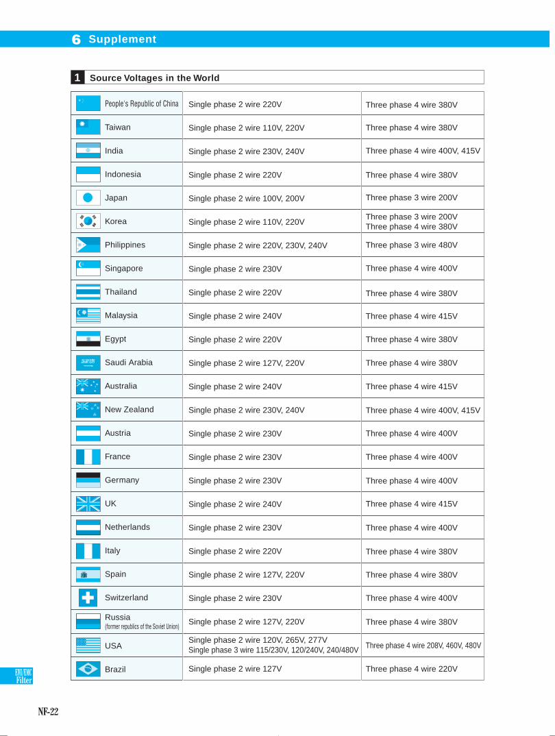
Supplement6
Source Voltages in the World1
People's Republic of China
Taiwan
India
Indonesia
Japan
Korea
Philippines
Singapore
Thailand
Malaysia
Egypt
Saudi Arabia
Australia
New Zealand
Austria
France
Germany
UK
Netherlands
Italy
Spain
Switzerland
Russia (former republics of the Soviet Union)
USA
Brazil Three phase 4 wire 220V
Three phase 4 wire 380V
Three phase 4 wire 380V
Three phase 4 wire 400V, 415V
Three phase 4 wire 380V
Three phase 3 wire 200V
Three phase 3 wire 200V Three phase 4 wire 380V
Three phase 3 wire 480V
Three phase 4 wire 400V
Three phase 4 wire 380V
Three phase 4 wire 415V
Three phase 4 wire 380V
Three phase 4 wire 380V
Three phase 4 wire 415V
Three phase 4 wire 400V, 415V
Three phase 4 wire 400V
Three phase 4 wire 400V
Three phase 4 wire 400V
Three phase 4 wire 415V
Three phase 4 wire 400V
Three phase 4 wire 380V
Three phase 4 wire 380V
Three phase 4 wire 400V
Three phase 4 wire 380V
Three phase 4 wire 208V, 460V, 480V
Single phase 2 wire 220V
Single phase 2 wire 110V, 220V
Single phase 2 wire 230V, 240V
Single phase 2 wire 220V
Single phase 2 wire 100V, 200V
Single phase 2 wire 110V, 220V
Single phase 2 wire 220V, 230V, 240V
Single phase 2 wire 230V
Single phase 2 wire 220V
Single phase 2 wire 240V
Single phase 2 wire 220V
Single phase 2 wire 127V, 220V
Single phase 2 wire 240V
Single phase 2 wire 230V, 240V
Single phase 2 wire 230V
Single phase 2 wire 230V
Single phase 2 wire 230V
Single phase 2 wire 240V
Single phase 2 wire 230V
Single phase 2 wire 220V
Single phase 2 wire 127V, 220V
Single phase 2 wire 230V
Single phase 2 wire 127V, 220V
Single phase 2 wire 127V
Single phase 2 wire 120V, 265V, 277V Single phase 3 wire 115/230V, 120/240V, 240/480V
ORDEM PROORESSO
me_nf05-22.indd NF-22me_nf05-22.indd NF-22 2015/06/18 18:31:052015/06/18 18:31:05