techtip: plc data exchange - eplan.help · techtip eplan platform version 2.8 version: november 26,...
TRANSCRIPT

TechTip
EPLAN Platform Version 2.8
Version: November 26, 2018
1
TechTip: PLC data exchange
Contents
1. Use ............................................................................................................................... 3
2. Exchanged data ........................................................................................................... 3
3. Recommended workflow in EPLAN ........................................................................... 4
3.1. Physical rack layout ............................................................................................. 4
3.1.1. Head station .................................................................................................... 4
3.1.2. Extension racks ............................................................................................... 5
3.1.3. Passive devices .............................................................................................. 5
3.2. I/O interconnection ............................................................................................... 6
3.2.1. Safety controllers ............................................................................................ 6
3.3. Network structure ................................................................................................. 7
3.3.1. Automatic connections between associated bus ports ..................................... 9
4. Export from EPLAN ................................................................................................... 11
4.1. Hardware data ..................................................................................................... 11
4.2. Assignment list ................................................................................................... 12
5. Import in EPLAN ........................................................................................................ 13
6. Preparation of parts data .......................................................................................... 14
7. Recommendation EPLAN macros ............................................................................ 15
8. AutomationML ........................................................................................................... 16
8.1. PC station ............................................................................................................ 16
8.2. Switches .............................................................................................................. 16
8.3. Bus adapter ......................................................................................................... 17
8.4. Subdevices .......................................................................................................... 17
9. SIEMENS STEP 7 TIA Portal and STEP 7 Classic ................................................... 18
9.1. STEP 7 TIA Portal ................................................................................................ 19
9.1.1. ET200SP ....................................................................................................... 19
9.1.2. ET200AL ....................................................................................................... 20
9.1.3. Passive devices in Ethernet-based networks................................................. 21
9.2. STEP 7 Classic .................................................................................................... 22

TechTip
EPLAN Platform Version 2.8
Version: November 26, 2018
2
9.3. Differences between STEP 7 TIA Portal and STEP 7 Classic ........................... 23
10. SIEMENS TIA Selection Tool .................................................................................... 26
11. Rockwell Automation Studio 5000 and Studio 5000 Architect 20/21 ..................... 27
11.1. Rockwell Automation Studio 5000 ................................................................. 27
11.2. Rockwell Studio 5000 Architect 20/21 ........................................................... 27
11.2.1. The following device families are supported .............................................. 27
11.2.2. The following connections are exchanged ................................................. 28
11.2.3. ControlLogix .............................................................................................. 28
11.2.4. CompactLogix / Point IO / Flex .................................................................. 28
12. Schneider-Electric Unity Pro XLS ............................................................................ 30
13. Beckhoff TwinCAT3 and TwinCAT2 ......................................................................... 31
13.1. TwinCAT3 ........................................................................................................ 31
13.2. TwinCAT2 ........................................................................................................ 32
13.2.1. CPU with integrated bus coupler ............................................................... 33
13.2.2. USB bus .................................................................................................... 34
13.3. Differences between TwinCAT3 and TwinCAT2 ............................................ 38
TechTip
EPLAN Platform Version 2.8
Version: November 26, 2018
3
1. Use
The multiple entry of data is avoided through the data exchange. This reduces the work load
across departments and avoids typing errors. The configuration is accelerated overall and
the planning quality is improved.
For the fundamental description of a property please refer to the current EPLAN help:
Terminals, Cables, Plugs, and PLC Information > PLC > Basics
EPLAN Properties: Overview
Further notes and specifications for individual properties can also be found in the TechTip:
Overview of the PLC properties.
With Version 2.7 of EPLAN Electric P8 numerous new check runs which help you in
configuring the data exchange were implemented in the PLC field.
2. Exchanged data
1. Hardware data
Rack structure with part information.
2. Symbol table (assignment list, table of variables or similar)
Contains the assignment of the symbolic address to a hardware address.
3. Network structure logical view (association of the devices to networks), not the exact
cabling.
The data exchange is based on a file that can be exchanged simply between the EPLAN
designer and the PLC programmer. Data that an editing program does not find in the
exchange file because the other editing program does not know them, are supplemented
during importing. EPLAN supplements the further required data from the parts management.
PLC configuration programs and EPLAN are based on different points of view.
EPLAN configures electrical engineering hardware details such as voltage supply, etc.
PLC configuration programs have a logical view for the software programming.
Through the different views of the programs and the current developments on the hardware
and software sector, the data exchange cannot always cover all the requirements.
The applies for example to passive items in the bus bundle and used field bus systems.
TechTip
EPLAN Platform Version 2.8
Version: November 26, 2018
4
3. Recommended workflow in EPLAN
3.1. Physical rack layout
Begin with the rack layout on a single-line schematic page.
Use single-line PLC boxes as main functions.
Advantages:
1. The hardware data of the used devices is planned through the rack layout. All the main
functions exist in the single-line representation. When this representation is copied, the
parts entered there are copied as well.
2. Individual functions (I/O connection points, power supply, bus ports, etc.) can be placed
via drag & drop from the PLC navigator.
3. The rack layout can be exchanged with PLC configuration programs.
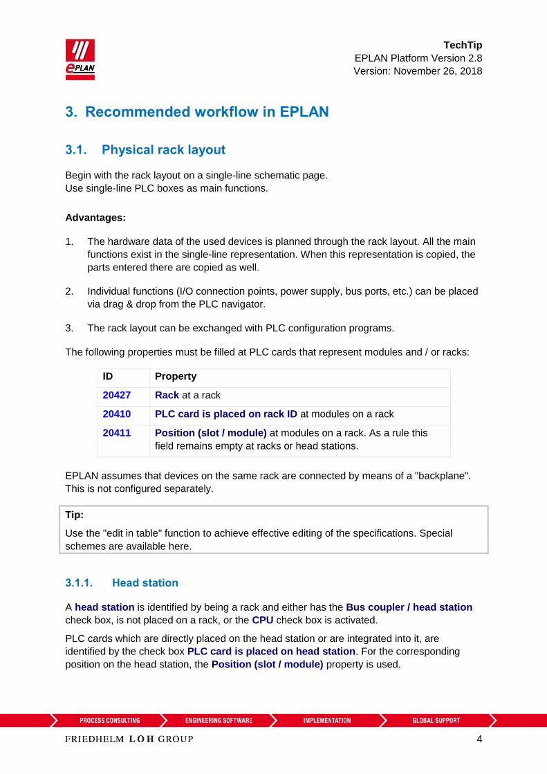
The following properties must be filled at PLC cards that represent modules and / or racks:
ID Property
20427 Rack at a rack
20410 PLC card is placed on rack ID at modules on a rack
20411 Position (slot / module) at modules on a rack. As a rule this
field remains empty at racks or head stations.
EPLAN assumes that devices on the same rack are connected by means of a "backplane".
This is not configured separately.
Tip:
Use the "edit in table" function to achieve effective editing of the specifications. Special
schemes are available here.
3.1.1. Head station
A head station is identified by being a rack and either has the Bus coupler / head station
check box, is not placed on a rack, or the CPU check box is activated.
PLC cards which are directly placed on the head station or are integrated into it, are
identified by the check box PLC card is placed on head station. For the corresponding
position on the head station, the Position (slot / module) property is used.

TechTip
EPLAN Platform Version 2.8
Version: November 26, 2018
5
For PLC cards that are adjoined next to the head station the PLC card is placed on head
station check box remains deactivated. For the corresponding position next to the head
station, the Position (slot / module) property is used.
The PLC card is placed on head station property is used during PLC data exchange in
AML format.
3.1.2. Extension racks
Extension racks have to be connected with the main rack via bus ports. Enter the
configuration project that belongs to the PLC box, use the "Local-Bus: Extension" bus system
at the bus port. Further properties are not required in the AML format. Activate the Do not
check bus ID check box at the bus port to suppress the error checking 004037.
3.1.3. Passive devices
Passive devices as well as devices that should not or cannot be exchanged with the PLC
configuration program can be used for the configuration of the bus topology.
1. Terminals, pins: To do so activate the Net-connecting check box on the Symbol /
function data tab.
4. Passive switches, bus repeaters, and similar units:
a) When using a PLC box: The PLC structure data tab remains completely empty,
no PLC-specific properties are required.
b) When using a black box: The settings for bus capable devices are not required
and remain empty. Details on the individual properties can also be found in the
TechTip: Overview of the PLC properties, Chapter "Settings at bus-capable
devices".
c) Bus ports are configured as "Network / Bus cable connection points, switch
connection point". Since these bus ports are treated as busbar connection points,
no specifications are required on the Bus data tab.
The network structure is exported in the AML format, the topology view ("port to
port switching") is incomplete, however.

TechTip
EPLAN Platform Version 2.8
Version: November 26, 2018
6
3.2. I/O interconnection
Place the I/O connection points with the associated sensors / actuators on multi-line
schematic pages.
Use bitwise representation (meaning one macro per channel) with functional grouping of the
devices.
Advantages:
1. Once macros have been created they can be used repeatedly for similar machine
functions.
2. I/O connection points or channels can be placed via drag & drop from the PLC navigator
or assigned.
3. You can check the assignment in the PLC navigator or on a PLC overview page.
3.2.1. Safety controllers
PLC cards that can check multiple connection points each for sameness or difference are
often used for safety controllers. At such safety-relevant components PLC configuration-
programs often treat multiple connection points as one channel. Since only one channel may
be active in EPLAN, identify further connection points of the channel with the property
Deactivated I/O connection point. This way these connection points are not filled with
ambiguous data for the PLC configuration program during the PLC data exchange.
To allow the post-addressing of these connection points in EPLAN, enter the same value in
the Channel designation field for each of the combined connection points.

TechTip
EPLAN Platform Version 2.8
Version: November 26, 2018
7
3.3. Network structure
Connect the single-line bus ports of the modules via autoconnecting. Bus ports are by default
net-connecting and signal-transmitting.
Advantages:
1. The network structure can be documented clearly by connecting the single-line bus
ports.
2. The network structure can be exchanged with PLC configuration programs. The logical
view (association of the devices to networks), is always exchanged. The export / import
of the exact cabling depends on the bus system and the exchange format used.
The following properties have to be filled at the bus ports:
ID Property
20406 Plug designation
20308 Bus system
20311 Physical network: Bus ID / item number
20413 Physical network: Name
20414 Logical network: Name
20447 Bus interface: Name at Ethernet-based bus systems
For the bus ports the Plug designation is identifying together with the Bus interface: Name
property.
In Ethernet-based bus systems, associated bus ports are combined to a bus interface via the
bus interface name. You can recognize this by the respective specifications in the manual or
through labels on the PLC card.

TechTip
EPLAN Platform Version 2.8
Version: November 26, 2018
8
Example for the Siemens module 6ES7516-3AN01-0AB0:
This PLC card has three bus ports for Ethernet-based bus
systems:
Connection
point
Plug designation Bus interface: Name
1 P1 R X1
2 P2 R X1
3 P1 X2
In the process the connection points 1 and 2 form a bus interface,
connection point 3 forms a second bus interface.
EPLAN treats the following bus systems equivalently during exporting / importing, because
they have the same hardware topology (Ethernet-based bus systems):
CC-Link IE
CC-Link IE Control
CC-Link IE Field
CC-Link IE Field Basic
EtherCAT
Ethernet
EtherNet/IP
Modbus TCP
Powerlink
PROFINET
SERCOS III
VARAN
TechTip
EPLAN Platform Version 2.8
Version: November 26, 2018
9
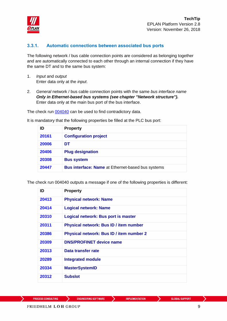
3.3.1. Automatic connections between associated bus ports
The following network / bus cable connection points are considered as belonging together
and are automatically connected to each other through an internal connection if they have
the same DT and to the same bus system:
1. Input and output
Enter data only at the input.
2. General network / bus cable connection points with the same bus interface name
Only in Ethernet-based bus systems (see chapter "Network structure").
Enter data only at the main bus port of the bus interface.
The check run 004040 can be used to find contradictory data.
It is mandatory that the following properties be filled at the PLC bus port:
ID Property
20161 Configuration project
20006 DT
20406 Plug designation
20308 Bus system
20447 Bus interface: Name at Ethernet-based bus systems
The check run 004040 outputs a message if one of the following properties is different:
ID Property
20413 Physical network: Name
20414 Logical network: Name
20310 Logical network: Bus port is master
20311 Physical network: Bus ID / item number
20386 Physical network: Bus ID / item number 2
20309 DNS/PROFINET device name
20313 Data transfer rate
20289 Integrated module
20334 MasterSystemID
20312 Subslot

TechTip
EPLAN Platform Version 2.8
Version: November 26, 2018
10
ID Property
20186 Marked for deletion
20446 Subnet mask
A check is carried out if the property to be checked is not empty at the second bus port.
If the property to be checked is empty at the first bus port and is filled at the second bus port,
a message is also output.

TechTip
EPLAN Platform Version 2.8
Version: November 26, 2018
11
4. Export from EPLAN
Before the export from EPLAN:
1. Check the project by means of the check runs from the 004 range. EPLAN makes
schemes available to you here that you use or adjust according to you requirements.
2. Delete the data not required at the auxiliary function (Project > Organize > Compress >
Settings > Remove project data > Remove PLC structure data at PLC auxiliary
functions).
4.1. Hardware data
1. The EPLAN export references a configuration project that is specified at all the
associated PLC boxes and bus ports.
2. Bus ports are represented single-line.
3. A device is identified with the CPU property (check box is activated).
The complete CPU name in the form [Configuration project].[Station
ID].[CPU identifier] must be unique project-wide.
4. The device identification is effected by means of
a) the PLC type designation property or
b) a device description file (e.g. GSD / GSDML / EDS file, property Device
description: File name property) and the Object description or
c) a device description file (e.g. GSD / GSDML / EDS file, property Device
description: File name property) and the Device description: Index in the file at
the data exchange in AML format.
The PLC type designation as a rule corresponds to the order number in the hardware
catalog of the respective PLC configuration program. The exact spelling is important.
Every PLC card can only have one device identification. A combination of several parts by
entering several PLC type designations, device description files or indexes is not supported.
PLC connection points of the following categories are not exchanged:
- General
- 2 connection points
- Power supply
- Card power supply.

TechTip
EPLAN Platform Version 2.8
Version: November 26, 2018
12
4.2. Assignment list
A PLC connection point (input / output) existing in a assignment list (symbol table) is
exported if the following conditions are fulfilled:
1. Only PLC connection points with the following function definitions are exchanged:
a. PLC connection point, DI
b. PLC connection point, DO
c. PLC connection point, AI
d. PLC connection point, AO
e. PLC connection point, multi-function with the type of signal
Digital input
Digital output
Analog input
Analog output
(Exception: PLC standard exchange format, all PLC connection points are exchanged
here)
2. A PLC connection point, multi-function is treated with its logic like the corresponding I/O
connection. For example
PLC connection point, multi-function, type of signal digital input corresponds to PLC
connection point, DI
3. A CPU exists in a configuration project.
4. The symbolic address is specified. The symbolic address must be unique within a
CPU.
5. The Data type (Boolean, byte, etc.) is specified.
6. The associated PLC box is assigned to a CPU by specifying the CPU: Name property.
The correct and complete specification of the CPU name at the PLC box is required so
that the assignment list (designation in the AML format: "TagTable") can be completely
exported.

TechTip
EPLAN Platform Version 2.8
Version: November 26, 2018
13
5. Import in EPLAN
During importing EPLAN supplements item data such as inputs / outputs from the parts data.
1. The device identification is effected by means of
a) the PLC type designation property or
b) a GSD / GSDML / EDS file (Device description: File name property) and the
Object description or
c) a GSD / GSDML / EDS file (Device description: File name property) and the
Index in file at the data exchange in AML format.
2. If items with placeholder characters (such as "*" and "?") are found in the PLC type
designation in the parts database during an import into EPLAN, the first suitable part is
used (PLC configuration programs do not always differentiate between parts that are
equivalent electrotechnically).
3. If multiple parts with the same PLC type designation are found during the import in
EPLAN, the first of those parts with the matching Object description (in as far as this
import file is available) is assigned. If no part has a matching object description, the first
found part is assigned.
4. If no appropriate part is found, a simple PLC box is created.
In these cases messages are output so that the imported devices can be checked
subsequently.
Device and PLC connection points that are available in the project but not in the import file,
have the Marked for deletion property assigned during import. These objects can be filtered
in the PLC navigator and subsequently be edited. Deactivate this property after the check or
editing.
TechTip
EPLAN Platform Version 2.8
Version: November 26, 2018
14
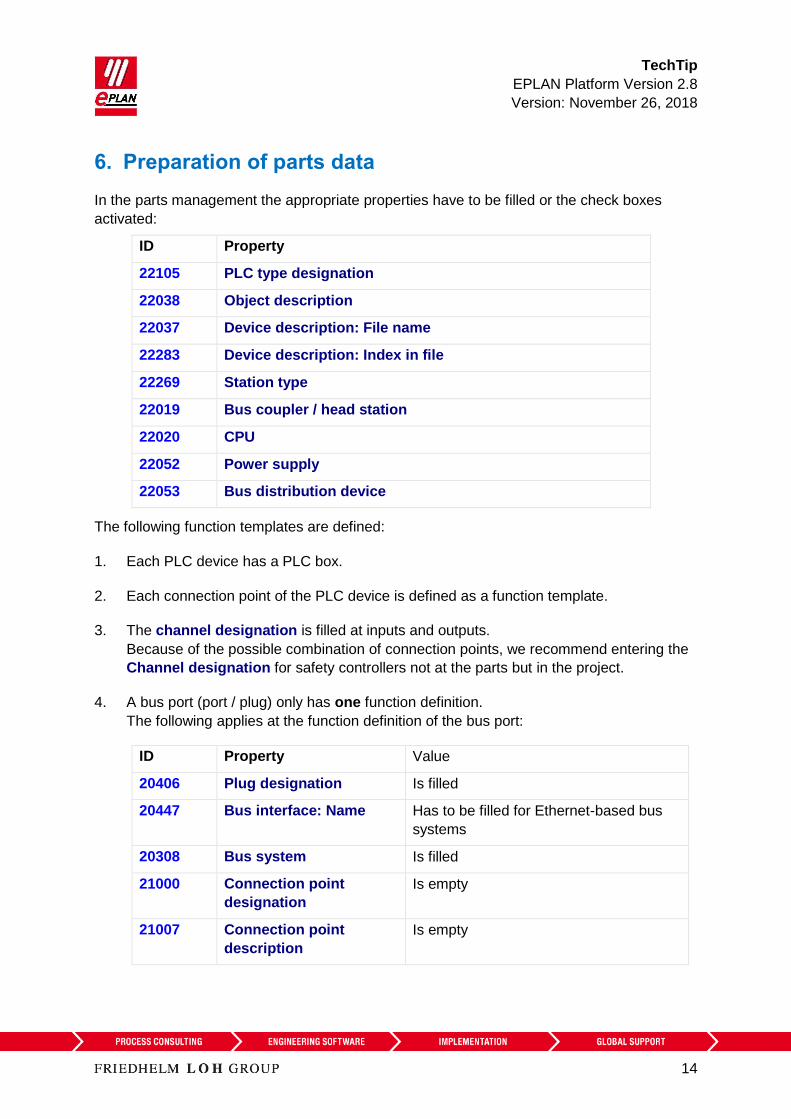
6. Preparation of parts data
In the parts management the appropriate properties have to be filled or the check boxes
activated:
ID Property
22105 PLC type designation
22038 Object description
22037 Device description: File name
22283 Device description: Index in file
22269 Station type
22019 Bus coupler / head station
22020 CPU
22052 Power supply
22053 Bus distribution device
The following function templates are defined:
1. Each PLC device has a PLC box.
2. Each connection point of the PLC device is defined as a function template.
3. The channel designation is filled at inputs and outputs.
Because of the possible combination of connection points, we recommend entering the
Channel designation for safety controllers not at the parts but in the project.
4. A bus port (port / plug) only has one function definition.
The following applies at the function definition of the bus port:
ID Property Value
20406 Plug designation Is filled
20447 Bus interface: Name Has to be filled for Ethernet-based bus
systems
20308 Bus system Is filled
21000 Connection point
designation
Is empty
21007 Connection point
description
Is empty

TechTip
EPLAN Platform Version 2.8
Version: November 26, 2018
15
7. Recommendation EPLAN macros
EPLAN recommends prepared macros for standardization:
1. Physical mapping of the rack structure.
Representation type "single-line", main function
2. Overview of complete I/O card as graphical control of the channel assignment.
Representation type "Overview"
3. Channel-wise mapping of the I/O for functionally oriented schematics.
Representation type "Multi-line"
(can also be dragged-and-dropped from symbols.)
4. Bus ports for mapping the network structure.
Representation type "Single-line"
(Separate compact representation or summary with 1.)
5. Voltage supply (power supply).
Representation type "Multi-line"
(Separate compact representation or summary with 1.)
Additional information on the creation of macros can be found in the TechTip-PLC-
Procedure-at-unknown-PLC-cards.
TechTip
EPLAN Platform Version 2.8
Version: November 26, 2018
16
8. AutomationML
Details of the individual properties are available in the TechTip PLC overview of the
properties.
Free symbolic addresses (which are not assigned to any PLC connection point) can be
exported and imported in AutomationML format via the PLC data exchange. After the import
of an AutomationML file, the free symbolic addresses existing there are available in EPLAN.
In the following sections you find special features on different devices.
8.1. PC station
1. The PC is a separate station and is configured as Rack "0". All other fields of the rack
assignment remain empty.
2. The Bus coupler / head station check box is to be activated.
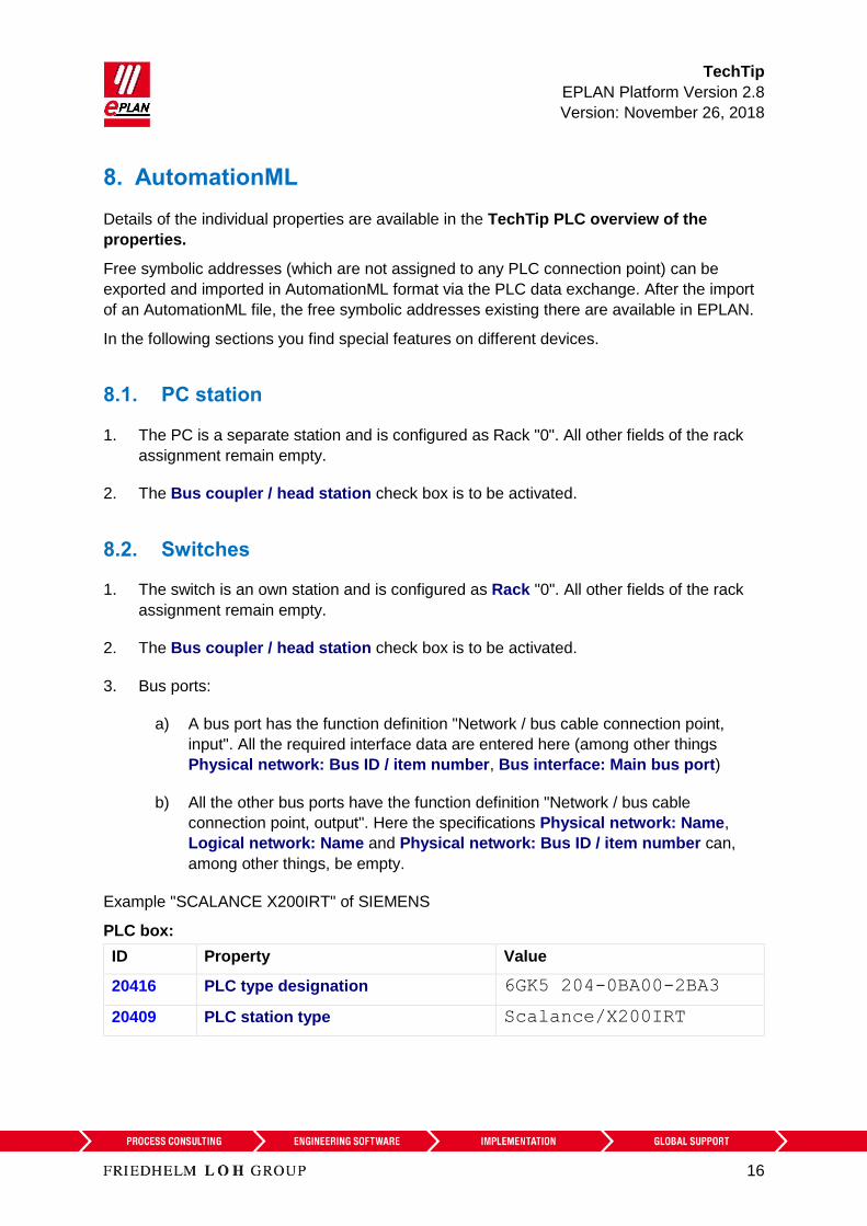
8.2. Switches
1. The switch is an own station and is configured as Rack "0". All other fields of the rack
assignment remain empty.
2. The Bus coupler / head station check box is to be activated.
3. Bus ports:
a) A bus port has the function definition "Network / bus cable connection point,
input". All the required interface data are entered here (among other things
Physical network: Bus ID / item number, Bus interface: Main bus port)
b) All the other bus ports have the function definition "Network / bus cable
connection point, output". Here the specifications Physical network: Name,
Logical network: Name and Physical network: Bus ID / item number can,
among other things, be empty.
Example "SCALANCE X200IRT" of SIEMENS
PLC box:
ID Property Value
20416 PLC type designation 6GK5 204-0BA00-2BA3
20409 PLC station type Scalance/X200IRT

TechTip
EPLAN Platform Version 2.8
Version: November 26, 2018
17
Bus ports:
20447 Bus interface: Name X1 (for all bus ports)
20406 Plug designation Px R, for all bus ports, whereby
x=1...n
Identify the first bus port as Bus interface: Main bus port and enter the relevant bus data
here.
8.3. Bus adapter
Stations of the ET200SP type or similar or of a SCALANCE router require bus adapters
(media modules) to which the network connections are connected.
These bus adapters are not configured as accessories but as PLC boxes with the associated
bus ports.
PLC box:
ID Property Value
20161 Configuration project Not empty
20416 PLC type designation e.g. 6ES7 193-6AR00-0AA0
20410 PLC card is placed on rack ID Like head station
20411 Position (slot / module) Not empty
20444 PLC card is placed on head station
8.4. Subdevices
A PLC card can consist of several integrated modules (subdevices) that each have separate
Address ranges and start addresses. Each subdevice is defined by corresponding properties.
Up to twelve subdevices can be specified (in the text below x designates the number of the
subdevice 1…12).
Subdevices do not have their own PLC type designation or specifications on a device
description file and are exported when they have at least one start address.
Note:
If a PLC card has no subdevices (meaning that it only consists of one module), definitions for
these can be omitted. The value "0" or "1" is entered (both values have the same meaning)
at the PLC subdevice: Index property at the associated PLC connection points.
Further information on the definition of subdevices is available from your PLC manufacturer.

TechTip
EPLAN Platform Version 2.8
Version: November 26, 2018
18
9. SIEMENS STEP 7 TIA Portal and STEP 7 Classic
1. The PLC type designation corresponds to the Siemens order number as it is also
specified in the hardware catalog of the PLC configuration program.
2. Racks are designated in ascending order with numerical values, beginning at "0". The
CPU is always plugged at Rack "0".
3. The Plug designation is only exchanged at bus ports.
4. The Start address always has to be specified at input and output modules. If a module
has an inputs and outputs, Start address 2 is used for the outputs.
5. A PLC connection point (input / output) is exported correctly when
a) A valid PLC address is specified.
b) The Data type is filled.
c) If the CPU: Name property is correctly filled at the associated PLC box.
6. The Station ID is specified at each module.
7. The Station type is entered
a) at the module that represents the CPU.
b) At each head station if no device description file is specified.
8. The MasterSystemID is specified at the bus master and has the following values:
a) PROFIBUS: in the range of 1 to 99
b) Ethernet-based bus systems: greater than or equal to 100.
Currently the following points are not supported in the AML format or in the CAx format
defined by SIEMENS:
Packed addresses (for example at input / output cards with 2-bit data width)
Symbolic addresses outside the process image.
Here the data exchange via the SDF format can be used.
Some connection point properties at analog modules (for example signal range)
Redundant control systems (H-series)

TechTip
EPLAN Platform Version 2.8
Version: November 26, 2018
19
9.1. STEP 7 TIA Portal
The data exchange is effected in AutomationML format, see Chapter "AutomationML".
Note:
The "Save GUID during the import" property has to be set for the round-trip engineering (can
be accessed under TIA Portal in the menu "Extras > Settings" in the "CAx" group).
In addition to the restrictions in Chapter 9, amongst other things, the following points are
currently not supported in the AML format:
Exchange of accessories. Therefore export your data without accessories (setting can be
accessed in the export dialog under "Options > Export accessories")
With few exceptions HMI devices cannot be exchanged
Please refer to the online help system of the TIA Portal under the search term "Restrictions
for CAx" for a detailed overview of all restrictions
1. For the identification of the address use "I" at inputs and "Q" at outputs, so that the
identifications do not change during an import.
2. Siemens remembers the DT.
3. If both the PLC type designation as well as a device description file are specified, the
PLC type designation is used for the data exchange.
4. The Channel designation is a numerical value equal to or greater than 0.
5. The Function text is transferred in several languages.
6. A head station is identified by itself being a rack that is not placed on any rack and at
which either the Bus coupler / head station check box or the CPU check box is
activated (see also Section "4.2.1 Head station").
7. The PLC card is placed on head station check box has to be activated for PLC cards
that are placed on the head station, are integrated into it and are not adjoined next to
the head station.
9.1.1. ET200SP
1. If the ET200SP station contains a CPU, no separate rack is configured. Instead the
CPU itself is the Rack "0". All other fields for rack assignment remain empty.
2. Additional information about the bus data exchange with an ET200SP is available in the
TechTip: Recommendation for PLC items with base and pluggable logic.
TechTip
EPLAN Platform Version 2.8
Version: November 26, 2018
20
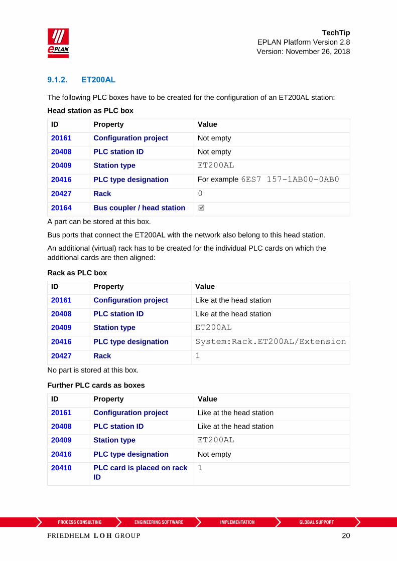
9.1.2. ET200AL
The following PLC boxes have to be created for the configuration of an ET200AL station:
Head station as PLC box
ID Property Value
20161 Configuration project Not empty
20408 PLC station ID Not empty
20409 Station type ET200AL
20416 PLC type designation For example 6ES7 157-1AB00-0AB0
20427 Rack 0
20164 Bus coupler / head station
A part can be stored at this box.
Bus ports that connect the ET200AL with the network also belong to this head station.
An additional (virtual) rack has to be created for the individual PLC cards on which the
additional cards are then aligned:
Rack as PLC box
ID Property Value
20161 Configuration project Like at the head station
20408 PLC station ID Like at the head station
20409 Station type ET200AL
20416 PLC type designation System:Rack.ET200AL/Extension
20427 Rack 1
No part is stored at this box.
Further PLC cards as boxes
ID Property Value
20161 Configuration project Like at the head station
20408 PLC station ID Like at the head station
20409 Station type ET200AL
20416 PLC type designation Not empty
20410 PLC card is placed on rack
ID
1

TechTip
EPLAN Platform Version 2.8
Version: November 26, 2018
21
ID Property Value
20411 Position (slot / module) Not empty
20253 [1] CPU name [1] Not empty (see CPU name)
A part can be stored at this box.
After a PLC data import the start addresses of the individual PLC cards have to be checked,
a value of "-1" for the (new) export is not valid and must be corrected. The start address must
either be empty or must have a value greater than / equal to "0".
Affected PLC cards can be determined in the PLC navigator with a filter. To this purpose
select the Start address of PLC card property as the filter criterion:
Active Negated Criterion Operator Value
Start address of PLC card = -1
Bus ports that connect individual racks of the ET200AL to each other are not contained in the
exchange file. Therefore configure these as device connection points in EPLAN.
9.1.3. Passive devices in Ethernet-based networks
It is possible to configure passive devices as an "EthernetDevice" so that the "port-to-port
interconnection" within an Ethernet-based network is exchanged during the bus data
exchange of passive devices (switches, bus repeaters or similar devices, see also Section
"4.2.3 Passive devices"). These devices have a specified number of port connection points
that are all configured as "Network / bus cable connection point, general" (also see Section
"4.3.1 Automatic connection between connected bus ports").
EthernetDevice as head station
ID Property Value
20161 Configuration project Not empty
20408 PLC station ID Not empty
20427 Rack 0
20411 Position (slot / module) 1
20409 Station type EthernetDevice
20416 PLC type designation System:DeviceItem.EthernetDevice.
Portx, whereby x corresponds to the number of
ports
20164 Bus coupler / head
station
TechTip
EPLAN Platform Version 2.8
Version: November 26, 2018
22
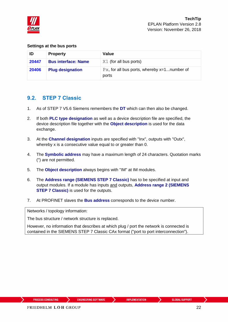
Settings at the bus ports
ID Property Value
20447 Bus interface: Name X1 (for all bus ports)
20406 Plug designation Px, for all bus ports, whereby x=1...number of
ports
9.2. STEP 7 Classic
1. As of STEP 7 V5.6 Siemens remembers the DT which can then also be changed.
2. If both PLC type designation as well as a device description file are specified, the
device description file together with the Object description is used for the data
exchange.
3. At the Channel designation inputs are specified with "Inx", outputs with "Outx",
whereby x is a consecutive value equal to or greater than 0.
4. The Symbolic address may have a maximum length of 24 characters. Quotation marks
(") are not permitted.
5. The Object description always begins with "IM" at IM modules.
6. The Address range (SIEMENS STEP 7 Classic) has to be specified at input and
output modules. If a module has inputs and outputs, Address range 2 (SIEMENS
STEP 7 Classic) is used for the outputs.
7. At PROFINET slaves the Bus address corresponds to the device number.
Networks / topology information:
The bus structure / network structure is replaced.
However, no information that describes at which plug / port the network is connected is
contained in the SIEMENS STEP 7 Classic CAx format ("port to port interconnection").
TechTip
EPLAN Platform Version 2.8
Version: November 26, 2018
23
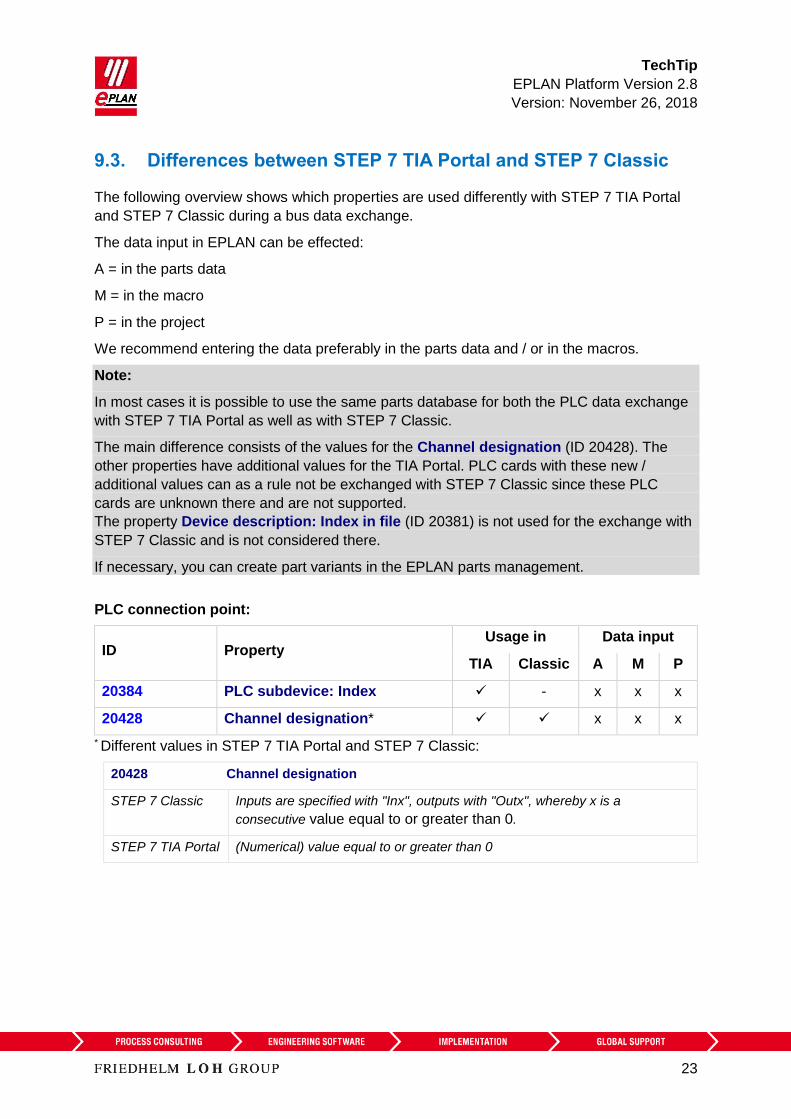
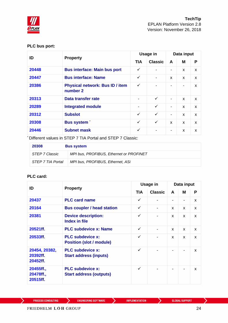
9.3. Differences between STEP 7 TIA Portal and STEP 7 Classic
The following overview shows which properties are used differently with STEP 7 TIA Portal
and STEP 7 Classic during a bus data exchange.
The data input in EPLAN can be effected:
A = in the parts data
M = in the macro
P = in the project
We recommend entering the data preferably in the parts data and / or in the macros.
Note:
In most cases it is possible to use the same parts database for both the PLC data exchange
with STEP 7 TIA Portal as well as with STEP 7 Classic.
The main difference consists of the values for the Channel designation (ID 20428). The
other properties have additional values for the TIA Portal. PLC cards with these new /
additional values can as a rule not be exchanged with STEP 7 Classic since these PLC
cards are unknown there and are not supported.
The property Device description: Index in file (ID 20381) is not used for the exchange with
STEP 7 Classic and is not considered there.
If necessary, you can create part variants in the EPLAN parts management.
PLC connection point:
ID Property Usage in Data input
TIA Classic A M P
20384 PLC subdevice: Index - x x x
20428 Channel designation* x x x
* Different values in STEP 7 TIA Portal and STEP 7 Classic:
20428 Channel designation
STEP 7 Classic Inputs are specified with "Inx", outputs with "Outx", whereby x is a
consecutive value equal to or greater than 0.
STEP 7 TIA Portal (Numerical) value equal to or greater than 0
TechTip
EPLAN Platform Version 2.8
Version: November 26, 2018
24
PLC bus port:
ID Property Usage in Data input
TIA Classic A M P
20448 Bus interface: Main bus port - - x x
20447 Bus interface: Name - x x x
20386 Physical network: Bus ID / item
number 2
- - - x
20313 Data transfer rate - - x x
20289 Integrated module - - x x
20312 Subslot - x x
20308 Bus system * x x x
20446 Subnet mask - - x x
* Different values in STEP 7 TIA Portal and STEP 7 Classic:
20308 Bus system
STEP 7 Classic MPI bus, PROFIBUS, Ethernet or PROFINET
STEP 7 TIA Portal MPI bus, PROFIBUS, Ethernet, ASi
PLC card:
ID Property Usage in Data input
TIA Classic A M P
20437 PLC card name - - - x
20164 Bus coupler / head station - x x x
20381 Device description:
Index in file
- x x x
20521ff. PLC subdevice x: Name - x x x
20533ff. PLC subdevice x:
Position (slot / module)
- x x x
20454, 20382,
20392ff.
20452ff.
PLC subdevice x:
Start address (inputs)
- - - x
20455ff.,
20478ff.,
20515ff.
PLC subdevice x:
Start address (outputs)
- - - x

TechTip
EPLAN Platform Version 2.8
Version: November 26, 2018
25
ID Property Usage in Data input
TIA Classic A M P
20417 Object description - x x x
20432,
20299
Address range (SIEMENS STEP
7 Classic),
Address range 2 (SIEMENS
STEP 7 Classic)
- x x x
20289 Integrated module - x x
20444 PLC card is placed on head
station
- x x x
20312 Subslot - - x x
20409 PLC station type * x x x
* Different values in STEP 7 TIA Portal and STEP 7 Classic:
20409 PLC station type
STEP 7 Classic S7300, S7400, S7400H, PC_BASED, HMI_BASED
STEP 7 TIA Portal S7300, S7400, S71200, S71500, ET200AL, PC, ET200ecoPN, ET200SP,
ET200ISP, ET200M, ET200S, ET200Pro, ASi, S7mEC, Scalance/X200IRT,
among other things
Tip:
In the TIA Portal the Device description: Index in file property is visible in the "Type
Identifier" field of the hardware catalog if it is enabled via the setting "Activate display of the
type identifier for devices and modules" (can be accessed in the menu "Extras > Settings" in
the group "Hardware configuration > Information on product support").

TechTip
EPLAN Platform Version 2.8
Version: November 26, 2018
26
10. SIEMENS TIA Selection Tool
The data exchange is effected in AutomationML format, see also Chapter "AutomationML".
The BaseUnits of an ET200 can also be exchanged as accessories with the TIA Selection
Tool, see also TechTip: Recommendation for PLC items with base and pluggable logic.
BaseUnits are considered under the following conditions during the PLC bus data exchange:
1. The data exchange is performed in the TIA Selection tool with the target system
"ECAD".
2. The BaseUnits are stored in the EPLAN parts management with a PLC type
designation.
For the export from EPLAN Electric P8, the accessories must be specified as an additional
part number at the electronics module. During an import in EPLAN Electric P8 the
accessories are entered as an additional part number at the electronics module.
Restrictions in the TIA Selection Tool during import:
- Symbolic addresses and function texts are not imported.

TechTip
EPLAN Platform Version 2.8
Version: November 26, 2018
27
11. Rockwell Automation Studio 5000 and Studio 5000 Architect 20/21
1. If both the PLC type designation as well as a device description file are specified, the
PLC type designation is used for the data exchange.
2. PLC type designation is called "Catalog number" at Rockwell.
3. The Function text (is called "Comment" for Rockwell) is transferred in multiple
languages.
4. The Symbolic address may not contain any blank.
5. The CPU property must be activated at the controller.
6. Rockwell remembers the DT.
7. If a project has to support both exchange formats, the properties Rack and PLC card
name must be filled identically.
11.1. Rockwell Automation Studio 5000
The data exchange is effected in AutomationML format, see also Chapter "AutomationML".
Note:
The new TechTip: PLC data exchange with Automation Studio 5000 of Rockwell is
available for the upgrade from Studio 5000 Architect 20/21 to the new AML format used in
Automation Studio 5000.
11.2. Rockwell Studio 5000 Architect 20/21
While the structure of the modules is defined in standard cases via the properties Rack ID
and Module is placed on rack ID, the PLC card name property must be used for the
Rockwell format instead of the Rack ID property.
11.2.1. The following device families are supported
ControlLogix (1756)
CompactLogix (1768/1769)
Point IO (1734)
Flex (1794/97)

TechTip
EPLAN Platform Version 2.8
Version: November 26, 2018
28
1. The tag name is transferred (Symbolic address ), Data type, Channel designation.
2. A rack (rack / chassis or DIN rail / rail) must always be configured.
3. The PLC card name property contains the name of the device in RsLogix.
4. EPLAN generates a unique Rockwell-conform GUID during exporting that is saved in
the PLC object ID property.
5. SubModules / Built-In Modules (for example 1769-L23x) are mapped via the Plug
designation.
11.2.2. The following connections are exchanged
ControlNet
DeviceNet
Ethernet
Compact Logix Expansion
- Only generic switches are supported (no Stratix switches).
- The exchange only takes Base Tags into consideration. Alias tags are not supported.
- The hardware address is not transferred.
11.2.3. ControlLogix
The position of PLC cards on a rack is managed by the Position (slot / module) property.
Counting direction is from left to right.
11.2.4. CompactLogix / Point IO / Flex
1. EndCaps are included in transferring.
2. When the rack is selected, a power supplyunit (PowerSupply) must always be specified
as well.
3. The method of counting of the position of the PLC cards on the rack is no longer only
from left to right, but can be effected in both directions.
4. The size of the rack must be specified by means of the properties Number of positions
in the rack and Number of positions in the rack (left).
5. The actual sequence of the devices on the rack is specified by means of the Sort code
(for position in rack) property.

TechTip
EPLAN Platform Version 2.8
Version: November 26, 2018
29
11.2.4.1. CompactLogix 1768
a) PowerSupply and Controller are not included in the count of the number of positions.
b) Devices are located on the right and left of the controller.
c) PowerSupply and devices / cards of the 1768 family are configured to the left of the
controller.
d) Devices / cards of the 1769 family are configured to the right of the controller.
11.2.4.2. CompactLogix 1769-L3x
a) Only the PowerSupply is not included in the count of the number of positions
b) Devices are located to the left and right of the PowerSupply.
11.2.4.3. CompactLogix 1769-L23x
a) The Number of positions in the track (left) property does not have to be set.
b) The embedded input / output modules are identified via the Plug designation.
11.2.4.4. Flex 1794/97
a) Basic modules 1794-TBX are not taken into consideration during the data exchange
b) The Number of positions in the track (left) property does not have to be set.
c) The Position (slot / module) property is not set at PowerSupply and Controller. To
the right of this counting begins at "0".
d) Flex Daughter Cards on the controller are managed in EPLAN by making the
controller a rack and configuring the Daughter Cards as PLC cards on this rack.

TechTip
EPLAN Platform Version 2.8
Version: November 26, 2018
30
12. Schneider-Electric Unity Pro XLS
1. A PLC connection point (input / output) is only exported if the following property is filled:
ID Property
20407 Channel designation
20405 Data type
2. The Station type contains the specification of the PLC card type and is to be specified
at each device.
3. At the "drop" station type the type of the drop is specified in the Object description.
4. Identify the power supply modules (activate the Power supply check box).
5. Power supply modules are always plugged into Slot / module "-1".
6. Counting of the slots / modules begins at "0" for the control families Premium or M340
and at "1" for the Quantum.
7. Racks are specified with their topological addresses in the form "\<Bus position>.<Node
number>\<Rack position>".
8. Exchanging of the bus systems depends on the used control family:
a) M340: Import of CANOpen
b) Premium: Import and export of Fipio
c) Quantum: Import and export of RIO or DIO bus
Currently some of the connection point properties at analog modules are not supported in the
format defined by Schneider Electric.

TechTip
EPLAN Platform Version 2.8
Version: November 26, 2018
31
13. Beckhoff TwinCAT3 and TwinCAT2
1. The PLC type designation as a rule consists of a two-digit character combination and
a four-digit numerical combination.
2. The Symbolic address complies with IEC 61131 and may not contain special
characters such as umlauts or double underlines.
13.1. TwinCAT3
The data exchange is effected in AutomationML format, see also Chapter "AutomationML".
Note:
The TechTip: PLC data exchange with TwinCAT3 from Beckhoff is available for the
upgrade from TwinCAT2 to the new AML format used in TwinCAT3.
1. If both PLC type designation as well as a device description file are specified, the PLC
type designation is used for the data exchange.
2. The Channel designation is a numerical value equal to or greater than 0.
3. The Function text is transferred in several languages.
4. Each stations begins with a bus coupler or a CPU. The associated check boxes (CPU or
Bus coupler / head station) have to be activated here. The Rack property has to be
filled with the value 0.
5. Each station has exactly one rack.
6. The bus ports of the backplane are not drawn exactly. The following PLC cards are
assigned to the CPU or the bus coupler, the PLC card is placed on rack ID property
has be filled with the value 0.
7. For EtherCAT the bus port network / bus cable connection point, general is used. The
Logical network: Bus port is master check box must be activated at the bus port at
which the bundle begins.

TechTip
EPLAN Platform Version 2.8
Version: November 26, 2018
32
13.2. TwinCAT2
1. Bus couplers with downstream connected PLC cards (C-bus / EtherCAT) are
considered as a module, meaning that the bus coupler is defined as a rack. The bus
ports of the backplane are not drawn, but rather the downstream PLC cards are
assigned to the bus coupler with the PLC card is placed on rack ID property. The bus
system and the bus address are specified at the PLC box.
2. At industrial PC solutions (with card) the card is drawn as a PLC box and identified as a
CPU. The bus data are assigned to the bus ports on the card.
3. The following bus ports are used on the card at a C-bus:
a) IN = Network / Bus cable-connection point, end
b) OUT = Network / bus cable connection point, source
c) At OUT the Logical network: Bus port is master check box has to be
activated.
4. At Embedded PC (CX) the PLC box is identified as a CPU. Here the type for the
interface of the subsequent bus ports is specified at the PLC type designation (for
example ETHERCATPROT). Afterwards any PLC cards (for example bus couplers) can
follow on the internal bus. Therefore the bus coupler to the subsequent bus ports has to
be identified as Bus coupler / head station. In addition the bus system at the PLC box
is specified here ("EtherCAT" or "Other bus systems" for C bus).
5. The following bus ports are used for EtherCAT:
a) Network / bus cable connection point, general
b) Network / bus cable connection point, input
c) Network / bus cable connection point, output
d) The Logical network: Bus port is master check box must be activated at the
CPU (the bus begins here).
6. TwinCAT2 always expects a CPU and a bus coupler in the export file.
7. Necessary port descriptions at bus ports in EtherCAT systems are stored in the
Channel designation property.

TechTip
EPLAN Platform Version 2.8
Version: November 26, 2018
33
13.2.1. CPU with integrated bus coupler
When using CPUs with integrated bus coupler configure two PLC boxes (main functions)
with an own device tag each (not nested, even if it is actually one device) in EPLAN.
CPU as PLC box
ID Property Value
20416 PLC type designation ETHERCATPROT
20161 Configuration project Not empty
20427 Rack 1
20411 Position (slot / module) 0
20167 CPU
20253 [1] CPU name [1] I/O – configuration
A part can be stored at this box.
Bus coupler as PLC box
ID Property Value
20416 PLC type designation EK1100
20161 Configuration project Like at the CPU
20410 PLC card is placed on rack ID 1
20411 Position (slot / module) 0
20164 Bus coupler / head station
20253 [1] CPU name [1] I/O – configuration
20289 Integrated module
20311 Physical network:
Bus ID / item number
Not empty
20308 Bus system EtherCAT
No part is stored at this box.
TechTip
EPLAN Platform Version 2.8
Version: November 26, 2018
34
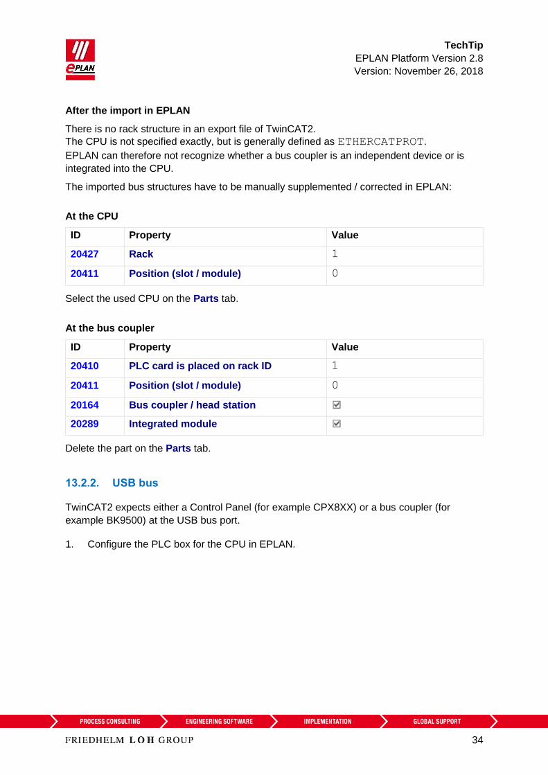
After the import in EPLAN
There is no rack structure in an export file of TwinCAT2.
The CPU is not specified exactly, but is generally defined as ETHERCATPROT.
EPLAN can therefore not recognize whether a bus coupler is an independent device or is
integrated into the CPU.
The imported bus structures have to be manually supplemented / corrected in EPLAN:
At the CPU
ID Property Value
20427 Rack 1
20411 Position (slot / module) 0
Select the used CPU on the Parts tab.
At the bus coupler
ID Property Value
20410 PLC card is placed on rack ID 1
20411 Position (slot / module) 0
20164 Bus coupler / head station
20289 Integrated module
Delete the part on the Parts tab.
13.2.2. USB bus
TwinCAT2 expects either a Control Panel (for example CPX8XX) or a bus coupler (for
example BK9500) at the USB bus port.
1. Configure the PLC box for the CPU in EPLAN.
TechTip
EPLAN Platform Version 2.8
Version: November 26, 2018
35
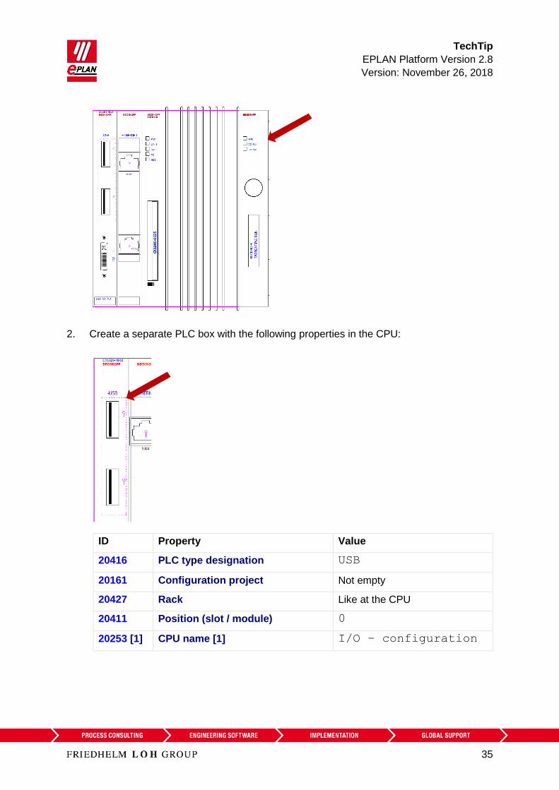
2. Create a separate PLC box with the following properties in the CPU:
ID Property Value
20416 PLC type designation USB
20161 Configuration project Not empty
20427 Rack Like at the CPU
20411 Position (slot / module) 0
20253 [1] CPU name [1] I/O – configuration
TechTip
EPLAN Platform Version 2.8
Version: November 26, 2018
36
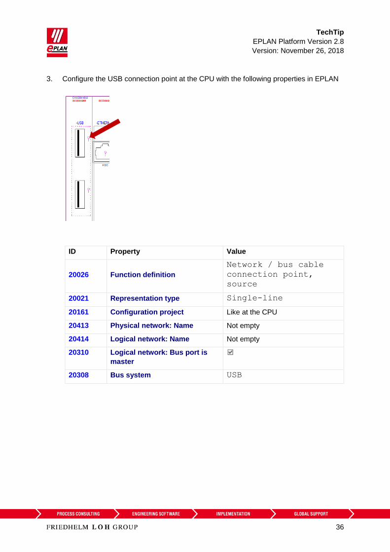
3. Configure the USB connection point at the CPU with the following properties in EPLAN
ID Property Value
20026 Function definition
Network / bus cable
connection point,
source
20021 Representation type Single-line
20161 Configuration project Like at the CPU
20413 Physical network: Name Not empty
20414 Logical network: Name Not empty
20310 Logical network: Bus port is
master
20308 Bus system USB

TechTip
EPLAN Platform Version 2.8
Version: November 26, 2018
37
4. Configure the USB connection point at the bus node (for example panel) with the
following properties in EPLAN:
ID Property Value
20026 Function definition
Network / bus cable
connection point,
input
20021 Representation type Single-line
20161 Configuration project Like at the CPU
20413 Physical network: Name Like at the master
20414 Logical network: Name Like at the master
20310 Logical network: Bus port is
master
20308 Bus system USB

TechTip
EPLAN Platform Version 2.8
Version: November 26, 2018
38
After the import in EPLAN
The imported bus structures have to be manually supplemented / corrected in EPLAN:
At the PLC box for the USB connection point
ID Property Value
20427 Rack Like at the CPU
20411 Position (slot / module) 0
Establish the single-line bus connections graphically (in as far they do not already exist). In
the process you are supported by the following check runs in finding missing connections:
Check run 004050
Check run 004051
13.3. Differences between TwinCAT3 and TwinCAT2
The following properties that were used with TwinCAT2 are not used anymore for the PLC
data exchange with TwinCAT3:
At PLC boxes:
ID Property
20308 Bus system
20311 Physical network: Bus ID / item number
At bus ports:
ID Property
20428 Channel designation