tecjet™ 52 gas regulation and metering valve/actuator system · tecjet™ 52 gas regulation and...
TRANSCRIPT

Installation and Operation Manual
TecJet™ 52 Gas Regulation and Metering Valve/Actuator System
Manual 26399 (Revision A)
WARNING—DANGER OF DEATH OR PERSONAL INJURY
WARNING—FOLLOW INSTRUCTIONS Read this entire manual and all other publications pertaining to the work to be performed before installing, operating, or servicing this equipment. Practice all plant and safety instructions and precautions. Failure to follow instructions can cause personal injury and/or property damage.
WARNING—OUT-OF-DATE PUBLICATION This publication may have been revised or updated since this copy was produced. To verify that you have the latest revision, be sure to check the Woodward website:
www.woodward.com/pubs/current.pdf The revision level is shown at the bottom of the front cover after the publication number. The latest version of most publications is available at:
www.woodward.com/publications If your publication is not there, please contact your customer service representative to get the latest copy.
WARNING—OVERSPEED PROTECTION The engine, turbine, or other type of prime mover should be equipped with an overspeed shutdown device to protect against runaway or damage to the prime mover with possible personal injury, loss of life, or property damage.
The overspeed shutdown device must be totally independent of the prime mover control system. An overtemperature or overpressure shutdown device may also be needed for safety, as appropriate.
WARNING—PROPER USE Any unauthorized modifications to or use of this equipment outside its specified mechanical, electrical, or other operating limits may cause personal injury and/or property damage, including damage to the equipment. Any such unauthorized modifications: (i) constitute "misuse" and/or "negligence" within the meaning of the product warranty thereby excluding warranty coverage for any resulting damage, and (ii) invalidate product certifications or listings.
CAUTION—POSSIBLE DAMAGE TO EQUIPMENT OR PROPERTY
CAUTION—BATTERY CHARGING To prevent damage to a control system that uses an alternator or battery-charging device, make sure the charging device is turned off before disconnecting the battery from the system.
CAUTION—ELECTROSTATIC DISCHARGE Electronic controls contain static-sensitive parts. Observe the following precautions to prevent damage to these parts. • Discharge body static before handling the control (with power to the control turned off,
contact a grounded surface and maintain contact while handling the control). • Avoid all plastic, vinyl, and Styrofoam (except antistatic versions) around printed circuit
boards. • Do not touch the components or conductors on a printed circuit board with your hands
or with conductive devices.
IMPORTANT DEFINITIONS • A WARNING indicates a potentially hazardous situation which, if not avoided, could result in
death or serious injury. • A CAUTION indicates a potentially hazardous situation which, if not avoided, could result in
damage to equipment or property. • A NOTE provides other helpful information that does not fall under the warning or caution
categories.
Revisions—Text changes are indicated by a black line alongside the text.
Woodward Governor Company reserves the right to update any portion of this publication at any time. Information provided by Woodward Governor Company is believed to be correct and reliable. However, no responsibility is assumed by Woodward Governor Company unless otherwise expressly undertaken.
© Woodward 2007 All Rights Reserved
Manual 26399 TecJet 52
Woodward i
Contents
REGULATORY COMPLIANCE ........................................................................ III CHAPTER 1. GENERAL INFORMATION ........................................................... 1 Introduction ............................................................................................................. 1 Connections to the TecJet 52 ................................................................................. 1 Programmable Features ......................................................................................... 2 Service Tool Software ............................................................................................ 2
CHAPTER 2. INSTALLATION.......................................................................... 5 Introduction ............................................................................................................. 5 Mounting ................................................................................................................. 5 Electrical Connections ............................................................................................ 6 Shielded Wiring ...................................................................................................... 7 Earth Ground .......................................................................................................... 7 Supply Voltage ....................................................................................................... 7 Keyswitch Input ...................................................................................................... 7 PWM Input .............................................................................................................. 9 CAN ID Inputs ....................................................................................................... 10 CAN Termination .................................................................................................. 10 CAN In .................................................................................................................. 11 CAN Out ............................................................................................................... 12 CAN Ground ......................................................................................................... 12 CAN Shield ........................................................................................................... 12 4–20 mA Analog Input .......................................................................................... 12 Status Output ........................................................................................................ 13 RS-232 Serial Communication Service Port ........................................................ 13 Auxiliary Power Output ......................................................................................... 13
CHAPTER 3. DESCRIPTION OF OPERATION ................................................. 14 Configuration ........................................................................................................ 14 Power-on Procedure ............................................................................................. 14 Normal Operation ................................................................................................. 14 Diagnostics ........................................................................................................... 15 Run Hours Counter ............................................................................................... 15 Position Limiter ..................................................................................................... 16 SAE J1939 Communications with Woodward EGS-02 ........................................ 16 CANopen Communications .................................................................................. 23 Position Hold Feature ........................................................................................... 27 General Specifications .......................................................................................... 28
CHAPTER 4. VALVE SIZING ........................................................................ 31 CHAPTER 5. SERVICE TOOL ....................................................................... 36 Overview ............................................................................................................... 36 Description ............................................................................................................ 36 Installation ............................................................................................................ 36 Troubleshooting the Driver ................................................................................... 38 Configuring the Driver ........................................................................................... 44 Load Configuration Settings ................................................................................. 53
CHAPTER 6. TROUBLESHOOTING ............................................................... 54 CHAPTER 7. MAINTENANCE ....................................................................... 59 General ................................................................................................................. 59 Limits of Applicability ............................................................................................ 59 Cleaning Procedure .............................................................................................. 59

TecJet 52 Manual 26399
ii Woodward
Contents
CHAPTER 8. SERVICE OPTIONS .................................................................. 61 Product Service Options ....................................................................................... 61 Returning Equipment for Repair ........................................................................... 62 Replacement Parts ............................................................................................... 63 How to Contact Woodward ................................................................................... 63 Engineering Services ............................................................................................ 64 Technical Assistance ............................................................................................ 65
DECLARATIONS ......................................................................................... 66
Illustrations and Tables Figure 1-1a. TecJet 52 Outline Drawing ................................................................. 3 Figure 1-1b. TecJet 52 Outline Drawing ................................................................. 4 Figure 2-1. TecJet 52 Wiring Diagram.................................................................... 8 Figure 2-2. TecJet 52 PWM Wiring ........................................................................ 9 Figure 2-3. TecJet 52 CAN Wiring for Isolated/Non-isolated Systems ................ 11 Figure 3-1. Address Claimed State Chart ............................................................ 22 Figure 4-1. Maximum Specialty Gas Flow Capacity of TecJet 52, 50 Plus,
Precision Flow, 50, and 110 ............................................................ 32 Figure 4-2. Minimum Specialty Gas Flow Capacity of TecJet 52, 50 Plus,
Precision Flow, 50, and 110 ............................................................ 33 Figure 4-3. Maximum Natural Gas Flow Capacity of TecJet 52, 50 Plus, Precision
Flow, 50, and 110 ............................................................................ 34 Figure 4-4. Minimum Natural Gas Flow Capacity of TecJet 52, 50 Plus, Precision
Flow, 50, and 110 ............................................................................ 35 Figure 5-1. Communication- Harness Connections ............................................. 37 Figure 5-2. Overview Screen ................................................................................ 39 Figure 5-3. Troubleshooting Screen ..................................................................... 40 Figure 5-4. Warnings Screen ................................................................................ 41 Figure 5-5. Errors Screen ..................................................................................... 42 Figure 5-6. Configuration Screen ......................................................................... 43 Figure 5-7. Identification Screen ........................................................................... 44 Figure 5-8. Edit TecJet Configuration, Demand Source....................................... 45 Figure 5-9. Edit TecJet Configuration, General .................................................... 46 Figure 5-10a. Edit TecJet Configuration, Flow (CAN Demand) ........................... 47 Figure 5-10b. Edit TecJet Configuration, Flow (Analog Demand) ........................ 48 Figure 5-10c. Edit TecJet Configuration, Flow (PWM Demand) .......................... 49 Figure 5-11. Edit TecJet Configuration, Failed Sensor Defaults .......................... 50 Figure 5-12. Edit TecJet Configuration, Filters ..................................................... 51 Figure 5-13a. Edit TecJet Configuration, CAN (Default) ...................................... 52 Figure 5-13b. Edit TecJet Configuration, CAN (User Configured) ....................... 52 Table 2-1. Mating Connector .................................................................................. 6

Manual 26399 TecJet 52
Woodward iii
Regulatory Compliance European Compliance for CE Marking: These listings apply to stationary industrial markets only and are limited only to those units bearing the CE Marking.
EMC Directive: Declared to 2004/108/EC COUNCIL DIRECTIVE of 15 December 2004 on the approximation of the laws of the Member States relating to electromagnetic compatibility and all applicable amendments.
Other European and International Compliance: Compliance with the following European Directives or standards does not qualify this product for application of the CE Marking. Machinery Directive: Compliant as a component with 98/37/EC COUNCIL
DIRECTIVE of 23 July 1998 on the approximation of the laws of the Member States relating to machinery.
Pressure Equipment
Directive: Exempt per Clause 4 of the Pressure Equipment Directive 97/23/EC of 29 May 1997 on the approximation of the laws of the Member States concerning pressure equipment.
North American Compliance: These listings are limited only to those units bearing the CSA identification.
CSA: CSA Certified for Class I, Division 2, Groups A, B, C & D, T3 at 85 °C Ambient for use in Canada and the United States. Certificate pending
This product is certified as a component for use in other equipment. The final combination is subject to acceptance by the authority having jurisdiction or local inspection. Wiring must be in accordance with North American Class I, Division 2 wiring methods, as applicable, and in accordance with the authority having jurisdiction. Special Conditions For Safe Use: Field Wiring must be suitable for at least 85 °C. Connect ground lug of TecJet™ 52 to earth ground. The TecJet 52 actuator should be protected from exposure to sunlight and rain. The Ingress Protection rating of the control depends on the use of proper mating connectors. Refer to Table 2-1 in the Installation section of this manual for information on the proper mating connectors for use with this control.
TecJet 52 Manual 26399
iv Woodward
WARNING—EXPLOSION HAZARD Do not remove covers or connect/disconnect electrical connectors unless power has been switched off or the area is known to be non-hazardous.
Substitution of components may impair suitability for Class I, Division 2 or Zone 2.
Do not clean equipment unless the area is known to be non-hazardous.
AVERTISSEMENT—RISQUE D’EXPLOSION Ne pas enlever les couvercles, ni raccorder / débrancher les prises électriques, sans vous en assurez auparavant que le système a bien été mis hors tension; ou que vous vous situez bien dans une zone non explosive.
La substitution de composants peut rendre ce matériel inacceptable pour les emplacements de Classe I, Division 2 ou Zone 2.
Ne pas nettoyer l’équipement à moins de se trouver dans un emplacement non dangereux.
CAUTION—WIRING Due to the hazardous location listing associated with this product, proper wire type and wiring practices are critical to operation.
Do not connect any cable grounds to “instrument ground”, “control ground”, or any non-earth ground system. Make all required electrical connections based on the wiring diagram per Figure 2-1
Manual 26399 TecJet 52
Woodward 1
Chapter 1. General Information
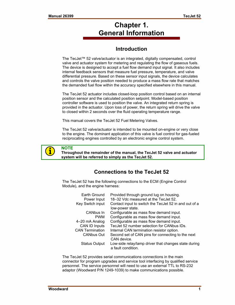
Introduction The TecJet™ 52 valve/actuator is an integrated, digitally compensated, control valve and actuator system for metering and regulating the flow of gaseous fuels. The device is designed to accept a fuel flow demand input signal. It also includes internal feedback sensors that measure fuel pressure, temperature, and valve differential pressure. Based on these sensor input signals, the device calculates and controls the valve position needed to produce a mass flow rate that matches the demanded fuel flow within the accuracy specified elsewhere in this manual. The TecJet 52 actuator includes closed-loop position control based on an internal position sensor and the calculated position setpoint. Model-based position controller software is used to position the valve. An integrated return spring is provided in the actuator. Upon loss of power, the return spring will drive the valve to closed within 2 seconds over the fluid operating temperature range. This manual covers the TecJet 52 Fuel Metering Valves. The TecJet 52 valve/actuator is intended to be mounted on-engine or very close to the engine. The dominant application of this valve is fuel control for gas-fueled reciprocating engines controlled by an electronic engine control system.
NOTE Throughout the remainder of the manual, the TecJet 52 valve and actuator system will be referred to simply as the TecJet 52.
Connections to the TecJet 52 The TecJet 52 has the following connections to the ECM (Engine Control Module), and the engine harness: Earth Ground Provided through ground lug on housing. Power Input 18–32 Vdc measured at the TecJet 52. Key Switch input Contact input to switch the TecJet 52 in and out of a
low-power state. CANbus In Configurable as mass flow demand input. PWM Configurable as mass flow demand input. 4–20 mA Analog Configurable as mass flow demand input. CAN ID Inputs TecJet 52 number selection for CANbus IDs. CAN Termination Internal CAN termination resistor option. CANbus Out Second set of CAN pins for connecting to the next
CAN device. Status Output Low-side relay/lamp driver that changes state during
a fault condition. The TecJet 52 provides serial communications connections in the main connector for program upgrades and service tool interfacing by qualified service personnel. The service personnel will need to use an external TTL to RS-232 adaptor (Woodward P/N 1249-1039) to make communications possible.
TecJet 52 Manual 26399
2 Woodward
Programmable Features Control setup is accomplished through the use of a PC (personal computer), Woodward Service Tool software, and TTL to RS-232 adaptor. The TecJet 52 is provided pre-configured with default settings and may not require additional setup. The features identified below are described in Chapter 5. Briefly, the programmable features include: • Configure Demand Source
o Jenbacher CAN (Proprietary protocol) o Analog 4–20 o PWM o EGS-01 (Proprietary protocol) o GECM (Proprietary protocol) o EGS-02 (SAE J1939 protocol)
• Configure General o Fuel Gas Defaults (K, Density) o Fuel Gas Temperature Warning Thresholds (High & Low °C) o Fuel Gas Pressure Warning Thresholds (High & Low mbar) o ΔP Warning Threshold (High & Low ΔP mbar)
• Configure Flow (Demand Source Dependent) o Demand Fail Limits (ms, mA, or %) o Scaling (High & Low mA or Duty Cycle % to Nl/s Flow)
• Configure Failed Sensor Defaults o Fuel Gas Temperature Sensor Default Temperature (°C) o Fuel Gas Pressure Sensor Default Downstream pressure (Table)
• Configure Filters o ΔP Filter Time Constant (sec) o Fuel Gas Pressure Filter Time Constant (sec) o Fuel Gas Temperature Filter Time Constant (sec) o Flow Demand Filter Time Constant (sec)
• Configure CAN (Demand Source Dependent) o Baud Rate Default (kbits/s) o Baud Rate User Configured
Baud Rate Prescaler: TSEG1: TSEG2: Synchronization Jump Width:
Service Tool Software The TecJet Service Tool software is a Microsoft Windows based GUI (graphic user interface) used to configure and troubleshoot the TecJet 52. The Service Tool Software is compatible with Microsoft Windows® XP, 2000, NT 4.0, Me, 98 and gives the end user the ability to: • Configure control settings based on application requirements • Load the configuration into the control • Monitor control parameters • View and reset fault conditions Detailed descriptions of software installation are available in Chapter 5.
Manual 26399 TecJet 52
Woodward 3
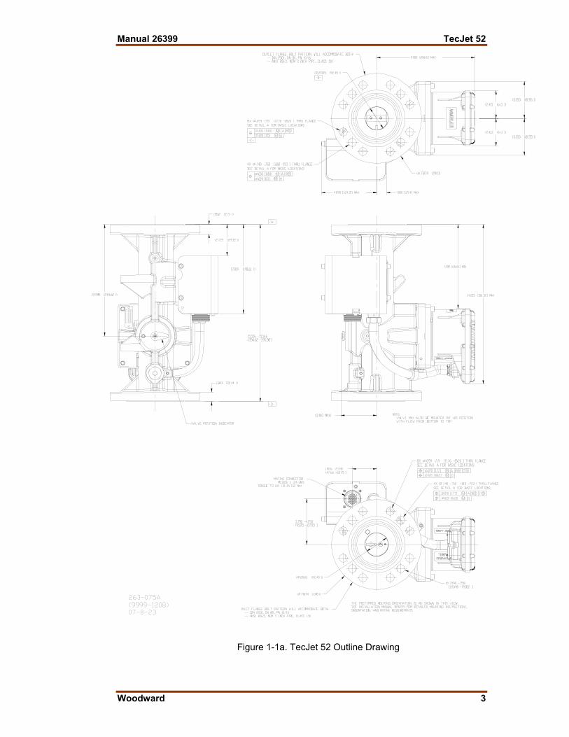
Figure 1-1a. TecJet 52 Outline Drawing
TecJet 52 Manual 26399
4 Woodward
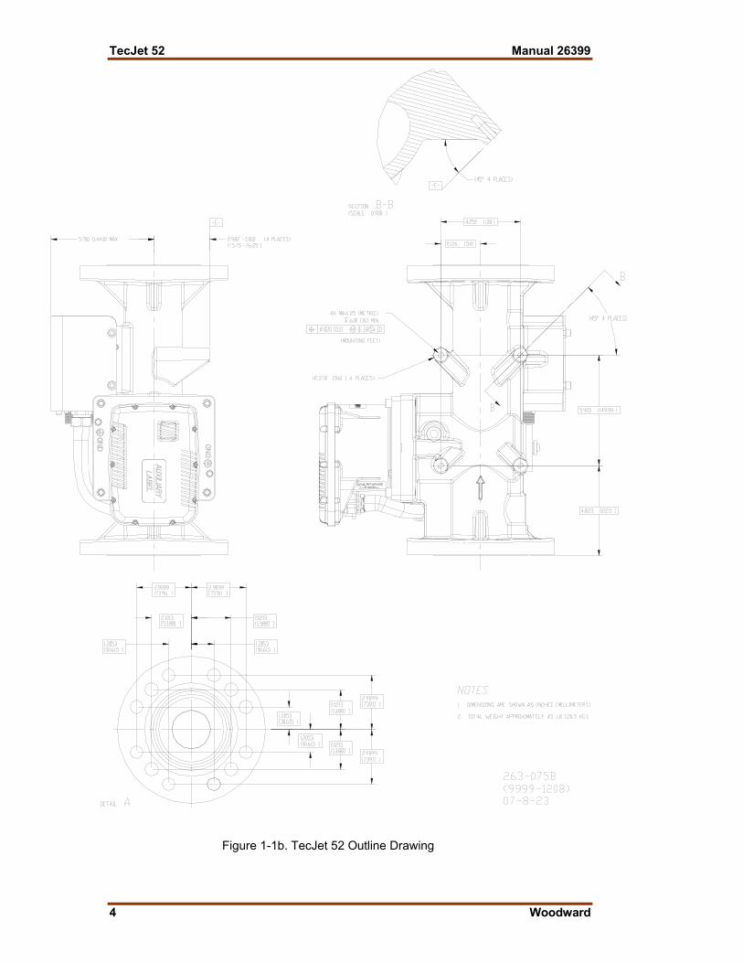
Figure 1-1b. TecJet 52 Outline Drawing

Manual 26399 TecJet 52
Woodward 5
Chapter 2. Installation
Introduction
WARNING—LIFTING The TecJet™ 52 weighs 17 kg (38 lb). In order to prevent injury, some form of lifting assistance (a lifting strap is recommended) should be used when handling the TecJet 52.
WARNING—EXTERNAL LEAKAGE The TecJet 52 valve is pressure tested at Woodward. Allowable external leakage is less than 2 SCCM or 0.00015 kg/h.
WARNING—VENTILATION The TecJet 52 valve is NOT equipped with an overboard drain in the event of gas leakage through its various seals. The valve should therefore be used in a well-ventilated area. A methane detector should be used if the valve will be used in an enclosed installation.
WARNING—LEAKAGE Leak-check all gaseous fuel connections. Leaking gaseous fuel can cause explosion hazards, property damage, or loss of life. Be careful when unpacking the TecJet 52. Check the assembly for signs of damage, such as bent or dented covers, scratches, and loose or broken parts. Be especially careful not to rest the TecJet 52 on the valve position pointer or on the actuator electrical connectors. Notify the shipper and Woodward if damage is found. If the TecJet 52 is to be painted, appropriate means must be used to mask the following items/areas: • All identification and warning labels • Main electrical connector • Junction between the valve shaft and the valve housing (this is a dynamic
junction next to the valve position pointer)
Mounting TecJet 52 orientation and mounting must be designed to reduce the possibility of fuel contamination. Orientation of the valve should be with the actuator +15/–90° relative to horizontal with the sensor module skyward. The axis of the valve bore can be +90/–15° relative to horizontal, with +90° representing the outlet of the valve pointing skyward. Installations with a bore axis orientation in the +15 to +90° range must incorporate means to prevent the buildup of moisture or other liquids in the fuel train. The valve has an arrow indicating flow direction cast into the outside of the valve housing. Washers should be placed between the valve body and any fasteners used. Give consideration to the strength of the mounting plate in order to support the 17.2 kg (38 lb) weight of the TecJet 52. Refer to the outline drawing in Figure 1-1 for dimensions and details relative to the valve inlet flange and outlet flange.
TecJet 52 Manual 26399
6 Woodward
For on-engine applications, a suitable bracket must be constructed to brace the valve mounting feet to a secure structure on the engine. See the outline drawing (Figure 1-1b) for the valve mounting feet hole and hole-location details. This mounting configuration should ensure that moment loads are not applied either through installation or thermal stress that could cause the valve to bind and lose functionality. The inlet and outlet piping of the TecJet 52 must be in accordance with ANSI/ISA-S75.02 to ensure the flow metering accuracy specified elsewhere in this manual. However, an inlet piping length as short as 6 diameters and an outlet piping length as short as 2 diameters can typically be used with a negligible loss in valve metering accuracy.
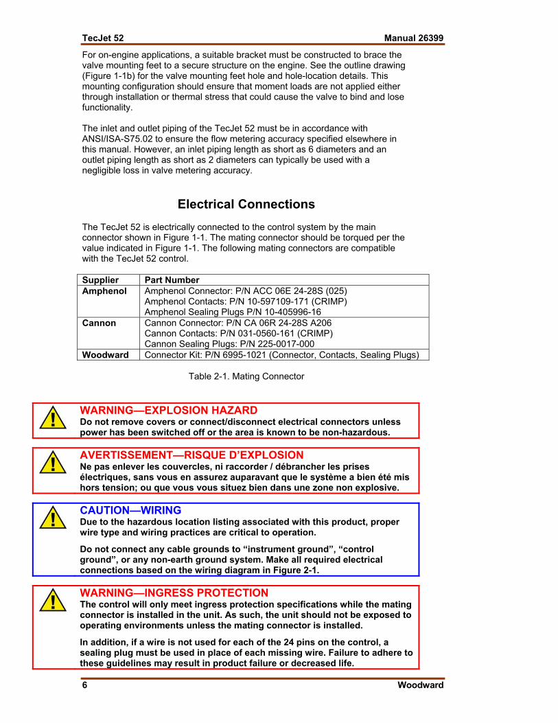
Electrical Connections The TecJet 52 is electrically connected to the control system by the main connector shown in Figure 1-1. The mating connector should be torqued per the value indicated in Figure 1-1. The following mating connectors are compatible with the TecJet 52 control. Supplier Part Number Amphenol Amphenol Connector: P/N ACC 06E 24-28S (025)
Amphenol Contacts: P/N 10-597109-171 (CRIMP) Amphenol Sealing Plugs P/N 10-405996-16
Cannon Cannon Connector: P/N CA 06R 24-28S A206 Cannon Contacts: P/N 031-0560-161 (CRIMP) Cannon Sealing Plugs: P/N 225-0017-000
Woodward Connector Kit: P/N 6995-1021 (Connector, Contacts, Sealing Plugs)
Table 2-1. Mating Connector
WARNING—EXPLOSION HAZARD Do not remove covers or connect/disconnect electrical connectors unless power has been switched off or the area is known to be non-hazardous.
AVERTISSEMENT—RISQUE D’EXPLOSION Ne pas enlever les couvercles, ni raccorder / débrancher les prises électriques, sans vous en assurez auparavant que le système a bien été mis hors tension; ou que vous vous situez bien dans une zone non explosive.
CAUTION—WIRING Due to the hazardous location listing associated with this product, proper wire type and wiring practices are critical to operation.
Do not connect any cable grounds to “instrument ground”, “control ground”, or any non-earth ground system. Make all required electrical connections based on the wiring diagram in Figure 2-1.
WARNING—INGRESS PROTECTION The control will only meet ingress protection specifications while the mating connector is installed in the unit. As such, the unit should not be exposed to operating environments unless the mating connector is installed.
In addition, if a wire is not used for each of the 24 pins on the control, a sealing plug must be used in place of each missing wire. Failure to adhere to these guidelines may result in product failure or decreased life.

Manual 26399 TecJet 52
Woodward 7
Shielded Wiring Shielded wiring is generally not required. The use of cable with individually shielded-twisted pairs is only required where indicated by the control wiring diagrams (Figure 2-1). However, some users may elect to run shielded wires for some I/O signals. Cable shields must be terminated as indicated in the control wiring diagram using the installation notes described below. DO NOT attempt to directly ground the shield at both ends since an undesired ground loop condition may occur. The TecJet 52 CAN shield connection pin is grounded through a high frequency capacitor (not directly grounded) and must be grounded in the wiring harness. Installation Notes • Wires exposed beyond the shield should be as short as possible, not
exceeding 50 mm (2 inches). • The shield termination wire (or drain wire) should be kept as short as
possible, not exceeding 50 mm (2 inches), and where possible the diameter should be maximized.
• Installations with severe electromagnetic interference (EMI) may require additional shielding precautions. Contact Woodward for more information.
Failure to provide shielding can produce future conditions which are difficult to diagnose. Proper shielding, when provided, at the time of installation is recommended to assure satisfactory operation of the product.
Earth Ground
Ground Lug = Earth Ground
In order to ensure CE compliance, the connection to the earth ground needs to meet the following requirements. First, the connection must be less than 183 cm (6 ft) in length. Second, the wire that is used must be at least 3.3 mm² (12 AWG) in size.
Supply Voltage
W = Power-In (+) Z = Power-In (–)
The supply voltage during normal operation must be 18 to 32 V, measured at the TecJet 52 connector. Steady state input current can reach 1.0 A, and transient input current may reach up to 4 A. The recommended power supply cable size is at least 1.3 mm² or 16 AWG. The power supply wiring must be fused outside of the valve. The recommended fuse is a 6 A slow blow fuse. Recommended maximum wire length from power source to TecJet 52 based on a 24 V Power Supply: 51 m (167 ft) using 16 AWG (1.3 mm²) stranded wire.
Keyswitch Input
F = Keyswitch
The keyswitch input is used to switch the TecJet 52 in and out of the run state. A high signal (connected to Aux. Power Out) will allow the valve to operate in a normal mode, and a low signal (connected to supply [–] or open connection) will force the valve to a minimum position (if possible) and then into a low power state. When the keyswitch input goes low, the valve will disable the driver circuitry after the software has gone through a shutdown procedure.

TecJet 52 Manual 26399
8 Woodward
CAN Hi In
CAN Lo In
CAN Shield
CAN Hi Out
CAN Lo Out
PWM In +
Keyswitch
Power In+
Power In -
TecJet 52
Jumper for CAN Termination Resistor
Z
W
F
L
K
B
A
Q
P
U
T
X
S
R
PWM In -
4-20mA Analog In +
4-20mA Analog In -
From PreviousCAN Device
To NextCAN Device
Battery
E Status Output (Discrete)
H
J Discrete/RS232 Common
V CAN Gnd
Y PWM Shield
G
RS232 SerialCommunication
CAN ID2
CAN ID1
N
M
D
C Aux. Power Out
Aux. Power Out
Load(relay coilor lamp)
1
1 1
3
TTL 2323
RS232 Tx
RS232 Rx
2
5
TTL to RS 232 Converter(Woodward 1249-1039)
2
Straight-Through9-Pin Serial Cable
(Must have all conductors)
NOTES:
2
USE AUX. POWER OUT (PINS C OR D) TO POWER THE KEYSWITCH INPUT AND THE STATUS OUTPUT LOAD,WHEN NEEDED.
3
THE STATUS OUTPUT IS A LOW-SIDE SWITCH THAT CAN BE OPERATED AT A MAXIMUM OF 42 V AND 500 MA.
THE MINIMUM WIRE SIZE FOR PINS W AND Z (POWER SUPPLY INPUTS) IS 16 AWG. FOR ALL OTHER I/O, THERECOMMENDED WIRE SIZE IS AT LEAST 18 AWG.
SHIELDING FOR THE ANALOG INPUT IS OPTIONAL4
4
5
5 THE SHIELDING FOR THE ANALOG INPUT (OPTIONAL) AND FOR THE PWM INPUT SHOULD BE TERMINATED ATTHE CUSTOMER END.
Figure 2-1. TecJet 52 Wiring Diagram
NOTE All signal and I/O wiring on the TecJet 52 is not to exceed 30 m (100 ft) in length. See “Supply Voltage” section for specific wire length limitations on the power supply inputs.
NOTE When wiring to pins V and/or J on the TecJet 52, be careful to ensure that the external circuit interface is isolated from battery ground, either by means of galvanic isolation or differential input/output. If it is not, a ground loop could be formed that can cause excess noise on the lines and/or damage to circuits.

Manual 26399 TecJet 52
Woodward 9
PWM Input K = PWM input (+) L = PWM input (–) The PWM input is configurable as the mass flow demand input. The PWM Input is designed for use with a push-pull type driver. Input Magnitude: 5–32 V differential input Input Impedance: 67 kΩ Input Type: Differential Input Frequency Range: 80–1100 Hz Isolation: none Resolution: 12 bits Accuracy: 1.0% of full scale up to 1 kHz @ 25 °C 1.5% of full scale above 1 kHz @ 25 °C Temperature Drift: ≤100ppm/°C Safe Input Common Mode Voltage: At least ±50 V PWM Detection Threshold 1.15 V nominal
Figure 2-2. TecJet 52 PWM Wiring
TecJet 52 Manual 26399
10 Woodward
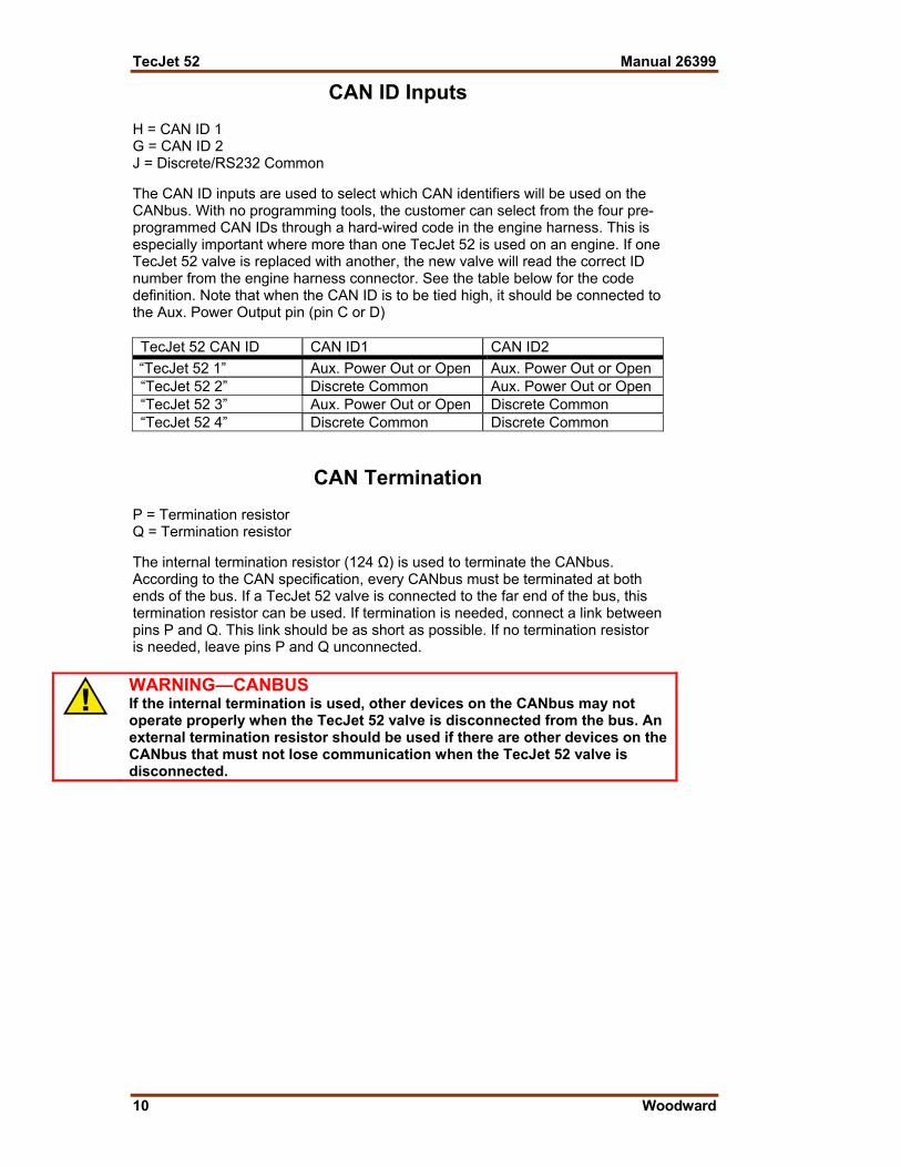
CAN ID Inputs H = CAN ID 1 G = CAN ID 2 J = Discrete/RS232 Common The CAN ID inputs are used to select which CAN identifiers will be used on the CANbus. With no programming tools, the customer can select from the four pre-programmed CAN IDs through a hard-wired code in the engine harness. This is especially important where more than one TecJet 52 is used on an engine. If one TecJet 52 valve is replaced with another, the new valve will read the correct ID number from the engine harness connector. See the table below for the code definition. Note that when the CAN ID is to be tied high, it should be connected to the Aux. Power Output pin (pin C or D) TecJet 52 CAN ID CAN ID1 CAN ID2 “TecJet 52 1” Aux. Power Out or Open Aux. Power Out or Open “TecJet 52 2” Discrete Common Aux. Power Out or Open “TecJet 52 3” Aux. Power Out or Open Discrete Common “TecJet 52 4” Discrete Common Discrete Common
CAN Termination P = Termination resistor Q = Termination resistor The internal termination resistor (124 Ω) is used to terminate the CANbus. According to the CAN specification, every CANbus must be terminated at both ends of the bus. If a TecJet 52 valve is connected to the far end of the bus, this termination resistor can be used. If termination is needed, connect a link between pins P and Q. This link should be as short as possible. If no termination resistor is needed, leave pins P and Q unconnected.
WARNING—CANBUS If the internal termination is used, other devices on the CANbus may not operate properly when the TecJet 52 valve is disconnected from the bus. An external termination resistor should be used if there are other devices on the CANbus that must not lose communication when the TecJet 52 valve is disconnected.
Manual 26399 TecJet 52
Woodward 11
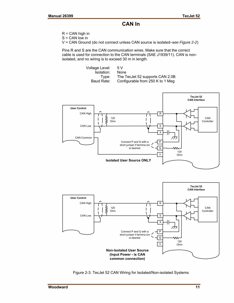
CAN In R = CAN high in S = CAN low in V = CAN Ground (do not connect unless CAN source is isolated–see Figure 2-2) Pins R and S are the CAN communication wires. Make sure that the correct cable is used for connection to the CAN terminals (SAE J1939/11). CAN is non-isolated, and no wiring is to exceed 30 m in length. Voltage Level: 5 V Isolation: None Type: The TecJet 52 supports CAN 2.0B Baud Rate: Configurable from 250 K to 1 Meg
120Ohm
User Control
CAN High
CAN Low
CAN Common
TecJet 52CAN Interface
R
S
X
V
CANController
P
Q
Isolated User Source ONLY
120Ohm
Connect P and Q with ashort jumper if termina ion
is desired.
Non-Isolated User Source(Input Power - is CANcommon connection)
120Ohm
User Control
CAN High
CAN Low
TecJet 52CAN Interface
R
S
X
V
CANController
P
Q120Ohm
Connect P and Q with ashort jumper if termina ion
is desired.
Figure 2-3. TecJet 52 CAN Wiring for Isolated/Non-isolated Systems
TecJet 52 Manual 26399
12 Woodward
CAN Out T = CAN high out U = CAN low out The CAN output pins are connected to the CAN input pins internally. They are provided for linking more then one TecJet 52 to the CANbus without the need for junction boxes or doubled terminations to connector pins. For example, the CANbus from the control may be connected to the input pins, and the output pins are connected to the second TecJet 52 input pins.
WARNING—CANBUS If a second device is connected to the CAN output pins, this device will lose communication if the TecJet 52 valve is disconnected.
CAN Ground V = CAN Ground Pin V is the CAN ground connection for the CAN communication wires.
NOTE Only use the CAN ground pin (V) if the CAN source is isolated. See Figure 2-2. If pin V is used with a non-isolated CAN source, a ground loop can be formed, which can disrupt communications and/or damage circuitry.
CAN Shield X = CAN Shield The CAN Shield can be used to terminate the shield of the CAN wiring. Internally, this pin is connected to the TecJet 52 chassis through a capacitor.
4–20 mA Analog Input A = 4–20 mA Analog Input (+) B = 4–20 mA Analog Input (–) The 4–20 mA Analog Input is configurable as the mass flow demand input. Input Impedance: 200 Ω Input Type: 4–20 mA differential Max Input Current: 26 mA Input Common Mode Range: At least ±50 V Common Mode Rejection Ratio: -60 dB minimum (DC to 500Hz) Safe Input Common Mode Voltage: At least ±200 V Accuracy: ±180μA @ 25 °C Temperature Drift: <50 ppm/°C
Manual 26399 TecJet 52
Woodward 13
Status Output E = Status Output J = Discrete/RS-232 Common The status output indicates whether the TecJet 52 valve is operating correctly. It will be "on" when the valve is operating normally and "off" when any warnings or errors are active. The Status Output electrical circuit is a low-side switch with the return current going to input power minus. It will be actively driven to Battery (-) when "on" and pulled to Battery (+) through a resistor when "off". The output load must be connected to the Status Output pin and to the Aux Power Out pin of the actuator. If the load is below 500 mA, the load can be driven directly from the output. It is possible to drive a relay if more current is needed for the load. If it is necessary to use an independent power supply instead of the Aux Power Out, then a protective fuse must be provided and the negative connection of the independent power supply must be tied to the actuator negative power input pin. The maximum voltage when the switch is in the “Off” state is 40 Vdc. The output is current protected and turns off if driven above 500 mA. If the short is removed, the output automatically returns to normal operation. Output Type: Low-Side Discrete Output Driver Drive Current: 500 mA max Max. Voltage: 42 Vdc
RS-232 Serial Communication Service Port M = Serial TX N = Serial RX J = Discrete/RS232 Common The RS-232 service port is used to configure, calibrate and trouble shoot the TecJet 52. The TecJet Service Tool can be downloaded from the Internet at www.woodward.com/software. The RS-232 wiring must meet the requirements in the EIA RS-232 Standard document. An external TTL to RS-232 converter (Woodward PN 1249-1039) is necessary to make communications possible with the Woodward TecJet Service Tool. The converter must be located a maximum of 1 meter from the TecJet 52. A connectivity kit can be purchased from Woodward to accomplish this. Further instructions for using this connectivity kit are provided in Chapter 5. Isolation: None Baud Rate: 38.4 Kbaud
Auxiliary Power Output C = Aux. Power Out D = Aux. Power Out The Auxiliary power output pins are designed as a convenient way to wire any of the inputs that require a pull-up to battery, such as keyswitch and the CAN ID pins. This is also a good way to supply power through a load to the Status Output. Using the Aux. Power Output for these functions is highly recommended for the best EMI performance. Please note that using the Aux. Power Out in the keyswitch circuit will protect the circuitry from harmful surges in power.
TecJet 52 Manual 26399
14 Woodward
Chapter 3. Description of Operation
WARNING—NOISE Due to typical noise levels in engine environments, hearing protection should be worn when working on or around the TecJet™ 52 valve/actuator.
WARNING—BURN HAZARD The surface of this product can become hot enough or cold enough to be a hazard. Use protective gear for product handling in these circumstances. Temperature ratings are included in the specification section of this manual.
CAUTION—FIRE PROTECTION Explosion Hazard—External fire protection is not provided in the scope of this product. It is the responsibility of the user to satisfy any applicable requirements for their system.
Configuration The valve can be configured to accept a flow demand from the analog input, the PWM input, or the CAN port. The configuration also includes user adjustable warning limits, and default values for failed sensor backup modes. The configuration can be viewed or changed online using the TecJet Service Tool. See Chapter 5 for information on installing the service tool.
Power-on Procedure When power is applied to the valve, it performs a diagnostic check. If there are no problems detected, the actuator is enabled with 1.36 N m (1.0 lb-ft) of torque, and the valve closes. If the flow demand source is configured for CAN, the valve reads the CAN ID input pins and begins sending diagnostic information on the CAN link. If a problem is detected, the valve will not operate and the status output will indicate a fault. Typically the TecJet 52 is continuously connected to the supply voltage. If the flow demand source is configured to Jenbacher CAN, the key switch has no effect. If the flow demand source is configured for anything else, the key switch input must be connected to a high signal (supply [+]) for the valve to operate. When the key switch is off, the valve closes, if possible, and the actuator driver that positions the valve is disabled to minimize the amount of current drawn from the battery.
Normal Operation If a valid flow demand and delta-pressure are present, the valve begins normal operation. The TecJet 52 calculates the area needed to provide the requested flow. This area is calculated using the delta pressure (inlet to outlet pressure differential), the absolute inlet fuel gas pressure, the fuel gas temperature, the fuel gas ratio of specific heats (K), the fuel gas density, and the calibration information stored in the valve. The actuator positions the valve to achieve the calculated area requirement.

Manual 26399 TecJet 52
Woodward 15
Diagnostics
WARNING—OVERSPEED The TecJet 52 may not return to minimum fuel for all faults. The engine, turbine, or other type of prime mover should be equipped with an overspeed, misfire, detonation detection shutdown device(s), that operate totally independently of the prime mover control device(s) to protect against runaway or damage to the engine, turbine, or other type of prime mover with possible personal injury or loss of life should the TecJet 52 system fail. An independent fuel shutoff device should also be used to shut off fuel flow in case the TecJet 52 system fails. The valve continuously performs a variety of diagnostic checks. Diagnostic events are classified as warnings, errors or status indications. The status output indicates the overall status of the valve. A brief summary: Warnings: A warning indicates a condition that may require operator attention or intervention. For example, the valve may be operating in conditions that are outside its specification range, or a failure has occurred for which there is a back-up mode of operation, possibly with reduced accuracy or performance. If any warnings are active, the status output turns “off”. Errors: An error indicates a problem that prevents the valve from operating. The valve closes, if possible, and remains inoperable until power is cycled. If the error persists, the valve requires service. If any errors are active, the status output turns “off”. Status indications: The valve provides the following status indications: • Zero flow detected—The flow demand is not present or is not valid. The
valve is closed and the status output turns “off”. • Zero pressure detected—The pressure across the valve is essentially
zero, so no flow can occur. The valve is closed and the status output turns “off”.
• Flow not reached—The valve cannot achieve the demanded flow given the present operating conditions (fuel gas temperature and pressure, delta pressure, gas K and density). The status output turns “off”.
• Overall status OK—There are no errors or warnings, and the Flow not detected, Zero flow detected, and Flow not reached status indications are not true. The status output turns “on”.
See Chapter 6 (Troubleshooting) for more information on abnormal operation.
Run Hours Counter The valve maintains a running hours counter that can be viewed or reset with the service tool. Running hours do not accumulate when the “Flow not detected” status indication is true.

TecJet 52 Manual 26399
16 Woodward
Position Limiter After the TecJet 52 is powered up and receives a flow demand, the valve remains closed until the delta-p sensor detects a non-zero valve delta-p. This non-zero delta-p is established when the fuel source is turned on. After sensing a non-zero valve delta-p, the valve is positioned according to an interpolated value from the position limiter table. This table contains three position vs. flow demand points. By limiting the valve position until fuel pressure is established, the delta-p required for the TecJet 52 to begin metering fuel is obtained at a lower fuel flow rate. This function ensures that adequate delta-p will be created, even with a substantially drooping fuel source, before allowing the TecJet 52 to begin metering fuel. An example of an abnormally low delta-p limiter: During start-up, if the valve is operating under very low differential pressure, and the valve indicates a "flow not reached" condition, but the valve position is less than 1.2 radians, then the valve position is being limited by the table values as described above. This situation can generally be resolved by increasing the valve inlet pressure to increase the differential pressure across the valve. SAE J1939 Communications with Woodward EGS-02
The TecJet 52 devices support CAN communications in the SAE J1939 Higher Layer Protocol format. Further detailed information regarding the J1939 Standards Collection can be purchased at www.sae.org. Information about CAN can be found at www.semiconductors.bosch.de. Specific information regarding TecJet 52 behavior is detailed below. All TecJet 52 J1939 messages use the CAN 2.0B 29-bit Extended Data Frame Format. Gaseous Fuel Command Transmission rep rate: 5 ms (Engine Control TecJet 52) Data length: 8 bytes Data page: 0 PDU format: 239 Note that this is the only Proprietary PDU Format 1 message allowed in J1939. PDU specific: 18, 125, 126, 127 depending on harness code Default priority: 0 (high) PGN: 0xEF12, 0xEF7D, 0xEF7E, 0xEF7F Bytes 1,2:Fuel specific gravity Data length: 2 bytes, unsigned Resolution: 0.0001/bit, 0 offset Range: 0 to 2 Bytes 3, 4: Ratio of Specific Heats Data length: 2 bytes, unsigned Resolution: 0.0001/bit, 0 offset Range: 0 to 2 Bytes: 5-8 Fuel Flow Rate Data length: 4 bytes, unsigned Resolution: 0.001 m^3/h/bit, 0 offset (normalized to 0 deg C, 1013
mbar Range: 0 to 4211081.215 m^3/hr (1169744.78194 Liters/second)
Manual 26399 TecJet 52
Woodward 17
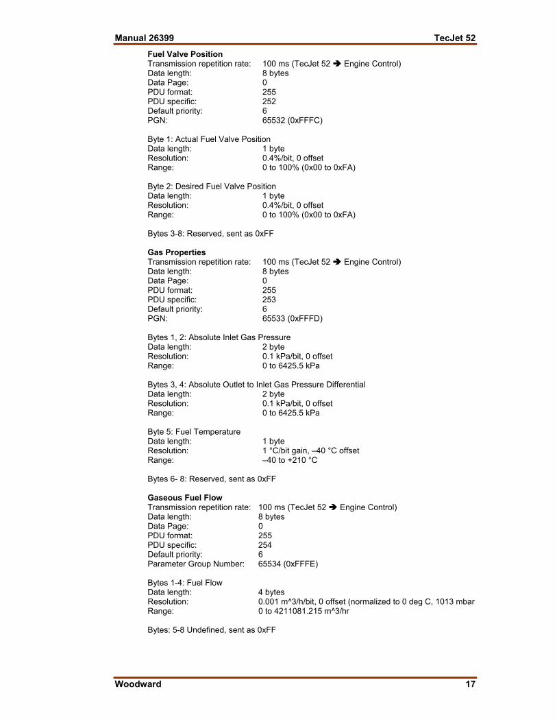
Fuel Valve Position Transmission repetition rate: 100 ms (TecJet 52 Engine Control) Data length: 8 bytes Data Page: 0 PDU format: 255 PDU specific: 252 Default priority: 6 PGN: 65532 (0xFFFC) Byte 1: Actual Fuel Valve Position Data length: 1 byte Resolution: 0.4%/bit, 0 offset Range: 0 to 100% (0x00 to 0xFA) Byte 2: Desired Fuel Valve Position Data length: 1 byte Resolution: 0.4%/bit, 0 offset Range: 0 to 100% (0x00 to 0xFA) Bytes 3-8: Reserved, sent as 0xFF Gas Properties Transmission repetition rate: 100 ms (TecJet 52 Engine Control) Data length: 8 bytes Data Page: 0 PDU format: 255 PDU specific: 253 Default priority: 6 PGN: 65533 (0xFFFD) Bytes 1, 2: Absolute Inlet Gas Pressure Data length: 2 byte Resolution: 0.1 kPa/bit, 0 offset Range: 0 to 6425.5 kPa Bytes 3, 4: Absolute Outlet to Inlet Gas Pressure Differential Data length: 2 byte Resolution: 0.1 kPa/bit, 0 offset Range: 0 to 6425.5 kPa Byte 5: Fuel Temperature Data length: 1 byte Resolution: 1 °C/bit gain, –40 °C offset Range: –40 to +210 °C Bytes 6- 8: Reserved, sent as 0xFF Gaseous Fuel Flow Transmission repetition rate: 100 ms (TecJet 52 Engine Control) Data length: 8 bytes Data Page: 0 PDU format: 255 PDU specific: 254 Default priority: 6 Parameter Group Number: 65534 (0xFFFE) Bytes 1-4: Fuel Flow Data length: 4 bytes Resolution: 0.001 m^3/h/bit, 0 offset (normalized to 0 deg C, 1013 mbar Range: 0 to 4211081.215 m^3/hr Bytes: 5-8 Undefined, sent as 0xFF

TecJet 52 Manual 26399
18 Woodward
Diagnostics and Status Transmission Rate: 200 ms (TecJet 52 Engine Control) Data Length: 8 bytes Data Page: 1 PDU Format: 255 PDU Specific: 255 Default Priority: 6 Parameter Group Number 65535 (0xFFFF) Bytes: 8 bytes of status. Byte 1 (Overall Status) Bit 0: OVERALL_STATUS_OK Bit 1: RESERVED Bit 2: ZERO_PRESSURE_DETECTED Bit 3: ZERO_FLOW_DETECTED Bit 4: FLOW_NOT_REACHED Bit 5: VALVE_POSITION_ERROR Bit 6: HIGH_ELEC_TEMP Bit 7: RESERVED Byte 2 Bit 0: ELEC_TEMP_FAIL_HIGH Bit 1: FGT_FAIL_HIGH Bit 2: DELTA_P_FAIL_HIGH Bit 3: FGP_FAIL_HIGH Bit 4: COIL_CURRENT_FAIL_HIGH Bit 5: RESERVED Bit 6: RESERVED Bit 7: POSITION_FAIL_HIGH Byte 3 Bit 0: ELEC_TEMP_FAIL_LOW Bit 1: FGT_FAIL_LOW Bit 2: DELTA_P_FAIL_LOW Bit 3: FGP_FAIL_LOW Bit 4: COIL_CURRENT_FAIL_LOW Bit 5: RESERVED Bit 6: RESERVED Bit 7: POSITION_FAIL_LOW Byte 4 Bit 0: RESERVED Bit 1: RESERVED Bit 2: RESERVED Bit 3: RESERVED Bit 4: ANALOG_INPUT_LOW_ERR Bit 5: ANALOG_INPUT_HIGH_ERR Bit 6: PWM_DUTY_CYCLE_LOW_ERR Bit 7: PWM_DUTY_CYCLE_HIGH_ERR Byte 5 Bit 0: BATTERY_VOLT_LOW_ERR Bit 1: FGT_LOW_LIMIT_ERR Bit 2: DELTA_P_LOW_LIMIT_ERR Bit 3: FGP_LOW_LIMIT_ERR Bit 4: BATTERY_VOLT_HIGH_ERR Bit 5: FGT_HIGH_LIMIT_ERR Bit 6: DELTA_P_HIGH_LIMIT_ERR Bit 7: FGP_HIGH_LIMIT_ERR

Manual 26399 TecJet 52
Woodward 19
Byte 6 Bit 0: RESERVED Bit 1: WATCHDOG_RESET Bit 2: RESERVED Bit 3: RESERVED Bit 4: CAN_FLOW_DEMAND_FAILED Bit 5: RESERVED Bit 6: TECJECT_SHUTDOWN Bit 7: TECJET_INTERNAL_FAULT Byte 7 Bit 0: RESERVED Bit 1: KEYSWITCH_STATE Bit 2: PARAMETER_ERR Bit 3: PARAMETER_VERSION_ERR Bit 4: MAIN_EEP_READ_FAIL Bit 5: MAIN_EEP_WRITE_FAIL Bit 6: READING_PARAMETERS Bit 7: SPI_ADC_ERR Byte 8 Bit 0: SENSE_5V_ERR Bit 1: SENSE_NEG9V_ERR Bit 2: SENSE_12V_ERR Bit 3: ADC_TEST_ERR Bit 4: CAN_TIMING_CHANGED Bit 5: EXCEPTION_ERR Bit 6: FACTORY_CAL_ERR Bit 7: RESERVED Address Claimed Address Claimed / Cannot Claim Message Address Claimed Transmission rate: on start-up, on request, response to Address
Claimed Data length: 8 bytes Data Page: 0 PDU format: 238 PDU specific: 255 Default priority: 6 Parameter Group Number: 60928 (0xEE00) Source Address 18, 125, 126, or 127 Byte 1, Bits 8-1: Least Significant Byte of Identity Number Byte 2, Bits 8-1: Second Byte of Identity Number Byte 3, Bits 8-6: Least significant 3 bits of Manufacturer Code Byte 3, Bits 5-1: Most significant 5 bits of Identity Number Byte 4, Bits 8-1: Most significant 8 bits of Manufacturer Code Byte 5, Bits 8-4: Function Instance Byte 5, Bits 3-1: ECU Instance Byte 6, Bits 8-1: Function Byte 7, Bits 8-2: Vehicle System Byte 7, Bit 1: Reserved Byte 8, Bit 8: Arbitrary Address Capable Byte 8, Bits 7-5: Industry Group Byte 8, Bits 4-1: Vehicle System Instance The Address Claimed message will be sent out shortly after power has
been applied to the TecJet 52 if the TecJet 52 is configured for the EGS-02 Flow Demand mode.
The Address Claimed message will be sent out in response to a Request for Address Claimed if the preferred address was successfully claimed or if the TecJet 52 has not won or lost address claiming.
The Request for Address Claimed can be sent to a specific Address or to the Global Destination Address, 255. The TecJet 52 will respond to a specific query, or one to the Global Destination Address, 255

TecJet 52 Manual 26399
20 Woodward
The Source Address for this transmit message will be 18 for TecJet 52 1, 125 for TecJet 52 2, 126 for TecJet 52 3, 127 for TecJet 52 4. Addresses are not re-programmable.
The Address Claimed Message will also be sent out if the TecJet 52 receives an Address Claimed message from the same Address as the receiving node and a lower priority (higher value) NAME. The entire 8-byte value of the NAME is used for arbitration with the Arbitrary Address Capable Field as the Most Significant Bit.
Cannot Claim Address Transmission rate: on start-up, on request, response to Address
Claimed Data length: 8 bytes Data Page: 0 PDU format: 238 PDU specific: 0 Default priority: 6 Parameter Group Number: 60928 (0xEE00) Source Address 254 Byte 1, Bits 8-1: Least Significant Byte of Identity Number Byte 2, Bits 8-1: Second Byte of Identity Number Byte 3, Bits 8-6: Least significant 3 bits of Manufacturer Code Byte 3, Bits 5-1: Most significant 5 bits of Identity Number Byte 4, Bits 8-1: Most significant 8 bits of Manufacturer Code Byte 5, Bits 8-4: Function Instance Byte 5, Bits 3-1: ECU Instance Byte 6, Bits 8-1: Function Byte 7, Bits 8-2: Vehicle System Byte 7, Bit 1: Reserved Byte 8, Bit 8: Arbitrary Address Capable Byte 8, Bits 7-5: Industry Group Byte 8, Bits 4-1: Vehicle System Instance The Cannot Claim Address message will be sent out if the TecJet 52
receives an Address Claimed message with the same Source Address as the receiving node and with a higher priority (lower value) NAME. The entire 8-byte value of the NAME is used for arbitration with the Arbitrary Address Capable Field as the Most Significant Bit.
The Cannot Claim Address will also be sent out in response to a Request for Address Claimed if the address was unsuccessfully claimed.
The Cannot Claim Address message will be sent out with a 0–153 millisecond pseudo-random delay between the reception of the triggering message and the transmission of the Cannot Claim Address message.
If the TecJet 52 cannot claim an Address a status bit will be set and the valve will shut down.
Manual 26399 TecJet 52
Woodward 21
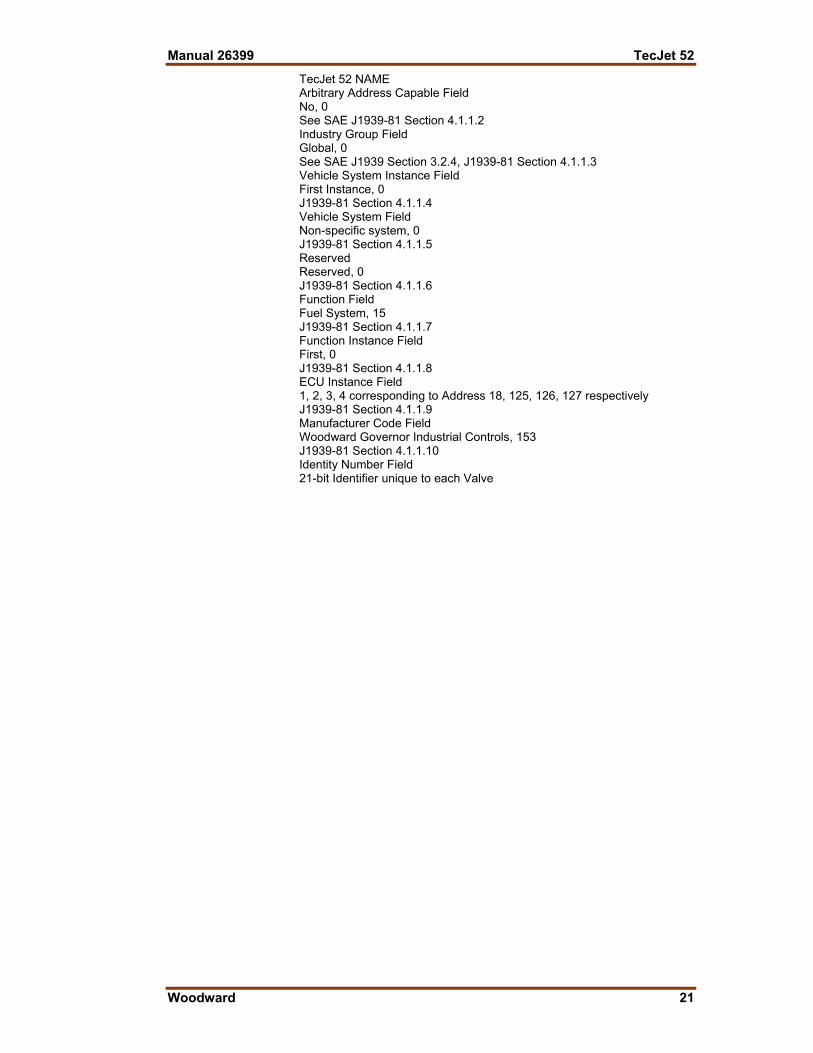
TecJet 52 NAME Arbitrary Address Capable Field No, 0 See SAE J1939-81 Section 4.1.1.2 Industry Group Field Global, 0 See SAE J1939 Section 3.2.4, J1939-81 Section 4.1.1.3 Vehicle System Instance Field First Instance, 0 J1939-81 Section 4.1.1.4 Vehicle System Field Non-specific system, 0 J1939-81 Section 4.1.1.5 Reserved Reserved, 0 J1939-81 Section 4.1.1.6 Function Field Fuel System, 15 J1939-81 Section 4.1.1.7 Function Instance Field First, 0 J1939-81 Section 4.1.1.8 ECU Instance Field 1, 2, 3, 4 corresponding to Address 18, 125, 126, 127 respectively J1939-81 Section 4.1.1.9 Manufacturer Code Field Woodward Governor Industrial Controls, 153 J1939-81 Section 4.1.1.10 Identity Number Field 21-bit Identifier unique to each Valve

TecJet 52 Manual 26399
22 Woodward
Start executing PowerOn Self Test
Normal Message Traffic
Random Delay beforesending Address
Claimed
Prioritizing AddressContention
Check for MessageCollision or Bus-off
condi ion
Cannot Claim Address
Delay before sendingCannot Claim
Priori izing AddressContention During
Initialization
Received Request for Address Claim -Reclaim current address
“Bus-off Error occurred or collision detected
POST Complete-Send Address Claim
Received a contendingAddress Claim
No Contending Address Claim
Received a contending Address Claim
Received Request ForAddress Claimed
Delay Complete -Send Cannot Claim Address
Contender’s NAME Less than mine-Send Cannot Claim Address
Contender’s NAME Less han mine-Send Cannot Claim Address
Contender’s NAME greater than mIne-Re-claim Current Address
Contender’s NAME greater than mIne-Re-claim Current Address
Delay Complete-Send Address Claim
Figure 3-1. Address Claimed State Chart
Manual 26399 TecJet 52
Woodward 23
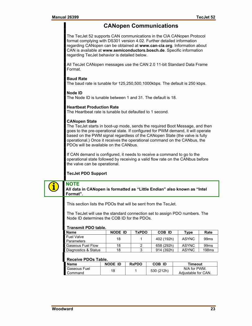
CANopen Communications The TecJet 52 supports CAN communications in the CIA CANopen Protocol format complying with DS301 version 4.02. Further detailed information regarding CANopen can be obtained at www.can-cia.org. Information about CAN is available at www.semiconductors.bosch.de. Specific information regarding TecJet behavior is detailed below. All TecJet CANopen messages use the CAN 2.0 11-bit Standard Data Frame Format. Baud Rate The baud rate is tunable for 125,250,500,1000kbps. The default is 250 kbps. Node ID The Node ID is tunable between 1 and 31. The default is 18. Heartbeat Production Rate The Heartbeat rate is tunable but defaulted to 1 second. CANopen State The TecJet starts in boot-up mode, sends the required Boot Message, and then goes to the pre-operational state. If configured for PWM demand, it will operate based on the PWM signal regardless of the CANopen State (the valve is fully operational.) Once it receives the operational command on the CANbus, the PDOs will be available on the CANbus. If CAN demand is configured, it needs to receive a command to go to the operational state followed by receiving a valid flow rate on the CANbus before the valve can be operational. TecJet PDO Support
NOTE All data in CANopen is formatted as “Little Endian” also known as “Intel Format”. This section lists the PDOs that will be sent from the TecJet. The TecJet will use the standard connection set to assign PDO numbers. The Node ID determines the COB ID for the PDOs. Transmit PDO table. Name NODE ID TxPDO COB ID Type RateFuel Valve Parameters 18 1 402 (192h) ASYNC 99ms
Gaseous Fuel Flow 18 2 658 (292h) ASYNC 99ms Diagnostics & Status 18 3 914 (392h) ASYNC 198ms Receive PDOs Table. Name NODE ID RxPDO COB ID Timeout Gaseous Fuel Command 18 1 530 (212h) N/A for PWM.
Adjustable for CAN.

TecJet 52 Manual 26399
24 Woodward
Transmit PDO 1 - Fuel Valve Parameters Transmission rate: 99ms Message type = “ASYNC” (does not require SYNC message) COB Id: 402 (0x192) default for Node Id = 18. All others 384+Node Id. Node ID = 18 (default address of TecJet when configured as TecJet #1) Data: Byte 1: Actual Fuel Valve Position Data length: 1 byte Resolution: 0.4%/bit, 0 offset (Multiply received value by 0.4 to recover % value) Range: 0 to 100% (0x00 to 0xFA) Byte 2: Desired Fuel Valve Position Data length: 1 byte Resolution: 0.4%/bit, 0 offset (Multiply received value by 0.4 to recover % value) Range: 0 to 100% (0x00 to 0xFA) Bytes 3-4: Absolute Inlet Gas Pressure Data length: 16 bits, integer Resolution: 0.1 kPa/bit, 0 offset (Multiply received value by 0.1 to recover kPa value) Range: 0 to 6425.5 kPa Bytes 5, 6: Absolute Outlet to Inlet Gas Pressure Differential Data length: 16 bits, integer Resolution: 0.1 kPa/bit, 0 offset (Multiply received value by 0.1 to recover kPa value) Range: 0 to 6425.5 kPa Byte 7: Fuel Temperature Data length: 1 byte Resolution: 1 C/bit gain, -40 C offset (Subtract 40 from received value to recover C value) Range: -40 to +210 C Byte 8: Reserved, sent as 0. Transmit PDO 2 - Gaseous Fuel Flow Transmission rate: 99ms Message type = “ASYNC” (does not require SYNC message) COB Id: 658 (0x292) default for Node Id = 18. All others 640+Node Id. Data: Bytes 1-4: Fuel Flow – Desired (Either the demand via PWM or CANopen) Data length: 4 bytes Resolution: 0.0002778 L/S/bit, 0 offset (Divide by 3600 to recover L/S value) Range: 0 to 1169744.78194 L/S Bytes 5-8: Gaseous Fuel Flow – Calculated, based on measured parameters Data length: 4 bytes Resolution: 0.0002778 L/S/bit, 0 offset (Divide by 3600 to recover L/S value) Range: 0 to 1169744.78194 L/S Transmit PDO 3 - Diagnostics and Status Transmission rate: 198ms Message type = “ASYNC” (does not require SYNC message) COB Id: 914 (0x392) default for Node Id = 18. All others 896+Node Id. Range: Boolean, 8 bytes of status. All reserved bits are set to 0. Data Length: 8 bytes

Manual 26399 TecJet 52
Woodward 25
Byte 1 (Overall Status) Bit 0: OVERALL_STATUS_OK Bit 1: HOLD_POSITION_WARN Bit 2: ZERO_PRESSURE_DETECTED Bit 3: ZERO_FLOW_DETECTED Bit 4: FLOW_NOT_REACHED Bit 5: VALVE_POSITION_ERROR Bit 6: HIGH_ELEC_TEMP Bit 7: RESERVED Byte 2 Bit 0: ELEC_TEMP_FAIL_HIGH Bit 1: FGT_FAIL_HIGH Bit 2: DELTA_P_FAIL_HIGH Bit 3: FGP_FAIL_HIGH Bit 4: COIL_CURRENT_FAIL_HIGH Bit 5: RESERVED Bit 6: RESERVED Bit 7: POSITION_FAIL_HIGH Byte 3 Bit 0: ELEC_TEMP_FAIL_LOW Bit 1: FGT_FAIL_LOW Bit 2: DELTA_P_FAIL_LOW Bit 3: FGP_FAIL_LOW Bit 4: COIL_CURRENT_FAIL_LOW Bit 5: RESERVED Bit 6: RESERVED Bit 7: POSITION_FAIL_LOW Byte 4 Bit 0: RESERVED Bit 1: RESERVED Bit 2: RESERVED Bit 3: RESERVED Bit 4: ANALOG_INPUT_LOW_ERR Bit 5: ANALOG_INPUT_HIGH_ERR Bit 6: PWM_DUTY_CYCLE_LOW_ERR Bit 7: PWM_DUTY_CYCLE_HIGH_ERR Byte 5 Bit 0: BATTERY_VOLT_LOW_ERR Bit 1: FGT_LOW_LIMIT_ERR Bit 2: DELTA_P_LOW_LIMIT_ERR Bit 3: FGP_LOW_LIMIT_ERR Bit 4: BATTERY_VOLT_HIGH_ERR Bit 5: FGT_HIGH_LIMIT_ERR Bit 6: DELTA_P_HIGH_LIMIT_ERR Bit 7: FGP_HIGH_LIMIT_ERR Byte 6 Bit 0: RESERVED Bit 1: WATCHDOG_RESET Bit 2: RESERVED Bit 3: RESERVED Bit 4: CAN_FLOW_DEMAND_FAILED Bit 5: RESERVED Bit 6: TECJECT_SHUTDOWN Bit 7: TECJET_INTERNAL_FAULT Byte 7 Bit 0: RESERVED Bit 1: KEYSWITCH_STATE Bit 2: RESERVED Bit 3: RESERVED Bit 4: RESERVED Bit 5: RESERVED Bit 6: RESERVED Bit 7: RESERVED

TecJet 52 Manual 26399
26 Woodward
Byte 8 Bit 0: RESERVED Bit 1: RESERVED Bit 2: RESERVED Bit 3: RESERVED Bit 4: RESERVED Bit 5: RESERVED Bit 6: RESERVED Bit 7: RESERVED Receive PDO 1 - Gaseous Fuel Command Maximum Reception rate: 3 ms (Engine Control to Tecjet50+) Message type = “ASYNC” (does not require SYNC message) Timeout: If Flow demand via CAN, the timeout for this message is adjustable from 10 to 10,000ms. COB Id: 530 (0x212) default for Node Id = 18. All others 512+Node Id. Node ID = 18 (default address of TecJet when configured as TecJet #1) Data length: 8 bytes Bytes 1,2:Fuel specific gravity Data length: 16 bits, integer Resolution: 0.0001/bit, 0 offset (multiply by 10,000 before sending) Range: 0.3101 to 2.0 (3101 to 20000 as scaled for transmission) Upon receipt of this message if the specific gravity is within the allowed
range, the TecJet+ is updated. The CAN data received is divided by 10,000 and multiplied by the density of
air, 1290.0 g/m^3 to get Normalized Density. Bytes 3, 4: Ratio of Specific Heats (K) Data length: 16 bits, integer Resolution: 0.0001/bit, 0 offset (multiply by 10,000 before sending) Range: 1.0001 to 2.0 (10001 to 20000 as scaled for transmission) Upon receipt of this message if the value is within the allowed range, the
TecJet+ will be updated with the raw data divided by 10,000. If CAN data has not been received during the current power cycle, a default
parameter, K will be used as configured by the service tool. Bytes: 5-8 Fuel Flow Rate Data length: 4 bytes, unsigned Resolution: 0.0002778 L/sec/bit, 0 offset (Divide by 3600 to recover L/sec value) Range: 0 to 1169744.78194 L/sec If the received flow demand is 0.00 or greater than 1169.74478194 L/sec,
the valve will be closed. If the TecJet is configured to expect the Flow Command via PWM, the Flow
Command in this message will be ignored. It can have any value since it will be completely ignored in that case.

Manual 26399 TecJet 52
Woodward 27
CANopen Data Summary PDO Summary Node/PDO represents the Node ID + PDO combination from the standard connection set.
Name CANopen Node/PDO Location Type Fuel specific gravity 18/1(R) Bytes 1-2 UINT16 Ratio of Specific Heats 18/1(R) Bytes 3-4 UINT16 Fuel Flow Rate 18/1(R) Bytes 5-8 UINT32 Actual Fuel Valve Position 18/1(T) Byte 1 UINT8 Desired Fuel Valve Position 18/1(T) Byte 2 UINT8 Absolute Inlet Gas Pressure 18/1(T) Bytes 3-4 UINT16 Absolute Outlet to Inlet Gas Pressure Differential 18/1(T) Bytes 5-6 UINT16
Fuel Temperature 18/1(T) Byte 7 UINT8 Gaseous Fuel Flow-Desired 18/2(T) Bytes 1-4 UINT32 Gaseous Fuel Flow-Calculated 18/2(T) Bytes 5-8 UINT32 Diagnostic Byte 1 18/3(T) Byte 1 BYTE Diagnostic Byte 2 18/3(T) Byte 2 BYTE Diagnostic Byte 3 18/3(T) Byte 3 BYTE Diagnostic Byte 4 18/3(T) Byte 4 BYTE Diagnostic Byte 5 18/3(T) Byte 5 BYTE Diagnostic Byte 6 18/3(T) Byte 6 BYTE Diagnostic Byte 7 18/3(T) Byte 7 BYTE Diagnostic Byte 8 18/3(T) Byte 8 BYTE
Position Hold Feature
WARNING—OVERSPEED This feature should only be used by qualified engine operators. This feature will hold the valve at the desired position regardless of the fuel demand from the engine controller, which could result in unexpected engine operation. The TecJet 52 has a position hold feature for use in analyzing or troubleshooting engine system operation. This allows qualified operators to bypass the normal flow control function and specify a fixed valve position. This mode is accessed in the Service Tool using the Tools Position Hold menu which can only be accessed with a password supplied by Woodward. The current valve position is displayed in the Position Hold dialog box. The valve remains in flow control mode while the Enable Position Hold check-box is unchecked. After the desired position is entered in the Position Hold Setting, checking the Enable Position Hold check-box causes the valve to operate in position hold mode where the valve position is controlled at the Position Hold Setting value. Un-checking the Enable Position Hold check-box restores normal flow control operation. Pressing OK closes the Position Hold window without changing the position hold settings. Position Hold is automatically disabled after 10 minutes. It is also disabled if the service tool connection is lost for more than 10 seconds.

TecJet 52 Manual 26399
28 Woodward
The Position Hold feature requires a valid flow command for position hold to function. The command is not used for positioning, but in order to control the position, the flow command must be valid. The position limiter function is also active so it may not be possible to achieve the desired position without increasing the flow demand. See the section “Position Limiter” earlier in this chapter. To avoid confusion, it is recommended to first achieve the desired flow, note the position, enter this position into the Position Hold setting, then activate the Position Hold feature. This process will avoid interaction with the Position Limiter unless the fuel pressure changes.
General Specifications Electrical Input Characteristics Input Voltage Range: 18–32 Vdc Maximum Steady State Input Current: 1 Amp at 24 Vdc Maximum Transient Input Current: 3.75 Amp at 24 Vdc Mechanical Characteristics Valve Maximum Effective Area: 1310 mm² (2.03 in²) Valve Minimum Effective Area: 25.8 mm² (0.040 in²) See section on valve sizing for detailed
information. Weight: 17.2 kg (38 lb) Mounting: See installation drawings (Figure 1-1) Fuel connections Filter Requirements: less than 50.0 µm See outline drawing for additional details. Dynamics Position Response: Bandwidth at +/- 0.5% amplitude >= 8 Hz at –3
db (24 V supply) Bandwidth at +/- 2% amplitude >= 15 Hz at –3
db (24 V supply) Step Response Slew Time: < 0.040 ms for a 10–90% and 90–10% step (24
V supply) Overshoot: < 2% of the step Flow Demand Response: Flow demand to position demand has latency of
< 4.5 ms Pressure Change Rejection: Same as demanded flow response with addition
of 10 ms lag on P1 measurement, 100 ms lag on delta pressure

Manual 26399 TecJet 52
Woodward 29
Environmental EMC EN61000-6-2 (2005): Immunity for Industrial Environments EN61000-6-4 (2001): Emissions for Industrial Environments Fuel Type The TecJet 52 operates on gases ranging from pipeline quality natural gas to specialty gas (such as landfill, digester, or other biogases). The TecJet 52 operates on gases ranging from pipeline quality natural gas to propane. Proper application of the valve for fuel flow, FGP, energy content, etc., is the responsibility of the OEM/packager/customer. The fuel gas flowing through the valve can consist of the following compounds with limits if they apply: Component Specification Gaseous hydrocarbons (methane, ethane, propane, etc.): No limit Carbon monoxide: No limit Carbon dioxide: No limit Hydrogen: <10% Oxygen: No limit Nitrogen: No limit Sulfur compounds including hydrogen sulfide: < 500 mg/10 kWh (< 2000 mg/10 kWh) Chlorine and fluorine compounds (typically chlorofluorocarbons): < 100 mg/10 kWh (< 400 mg/10 kWh) Silicon: < 5 mg/10 kWh (< 20 mg/10 kWh) Ammonia: < 50 mg/10 kWh Oil or hydrocarbons in liquid (mist form): < 5 mg/10 kWh Fine particulates, including silicon (less than 1.0 µm): < 3 mg/10 kWh Overall the gas Specific Gravity should be between 0.4 and 2.0 for the TecJet 52. The energy content should be between 1 and 9.5 kWh/nm³. The values in ( ) are allowed, but may result in reduced valve life. The above fuel limits can be converted to ppm by multiplying the given number by the LHV of the fuel in question, then dividing by 36. The LHV must be in units of MJ/kg. Pressures Inlet fuel gas pressure (FGP) should normally be between 876 and 1289 mbar absolute. Keep in mind that for a given gauge FGP value, absolute FGP will decrease with increasing altitude above sea level. The Inlet FGP sensor will compensate for barometric pressure to 3000 m. Pressures below 876 mbar are allowed at high load operation assuming that the gas differential pressure requirements are still met. The TecJet 52 fuel gas differential pressure (delta-p) should be between 69 and 345 mbar. Delta-p below this range is allowed during cranking and idle conditions, but accuracy of the valve will be reduced. For delta-p above 276 mbar, flow accuracy will also decrease, and a reduction in valve stability may occur. Refer to the Accuracy section later in this chapter for further details. Minimum proof pressure for the TecJet 52 is 0.52 bar gauge. Minimum burst pressure for the TecJet 52 is 1.72 bar gauge.

TecJet 52 Manual 26399
30 Woodward
Temperature The following are the temperature specifications for the TecJet 52: • Steady State Ambient Temperature: –20 to +85 °C (–4 to 185 °F) • Long Term Storage Temperature: –40 to +45 °C (–40 to +113 °F)* • Short Term Storage Temperature: –40 to +105 °C (–40 to +221 °F) * • Fuel Gas Inlet Temperature: 0 to 65 °C (32 to 149 °F) * The unit is un-powered during storage temperature. Vibration and Shock Random Vibration: Exceeds WGC RV2, 10–2000 Hz @ 0.1 G²/Hz (12.8
Grms) Shock: Per US MIL-STD-810C, Method 516.2, Procedure 1,
(40 g) Ingress Protection IP56 per IEC 60529, (Dust ingress, water ingress) Flow Characteristics Accuracy The TecJet 52 meters fuel accurately such that the engine starts consistently and accelerates smoothly to idle speed. The required fuel delivery up to 7% of valve maximum rated effective area is within ±20% of the mass flow demand. Throughout the load range, from idle to 100% load, the TecJet 52 regulates the fuel delivery accurately relative to the fuel flow demand in order to reduce combustion emissions and protect the engine against detonation. The accuracy is within ±10% of the mass flow demand from >7% to 25% of valve maximum rated effective area and within ±6% of the mass flow demand above 25% of valve maximum rated effective area. For delta-p above 275 mbar, an additional 1.5%, 1%, and 0.5%, respectively, should be added to the accuracy values stated above. Delta pressure below the minimum specified delta pressure would also significantly affect the accuracy values stated above.

Manual 26399 TecJet 52
Woodward 31
Chapter 4. Valve Sizing
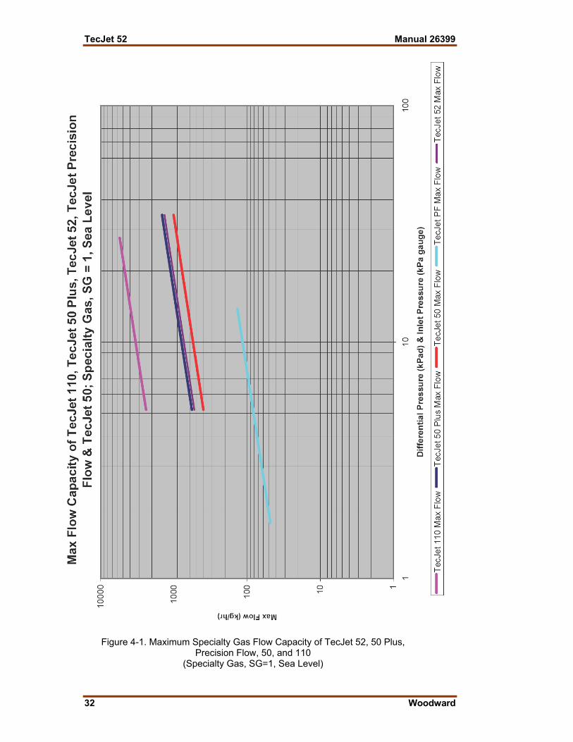
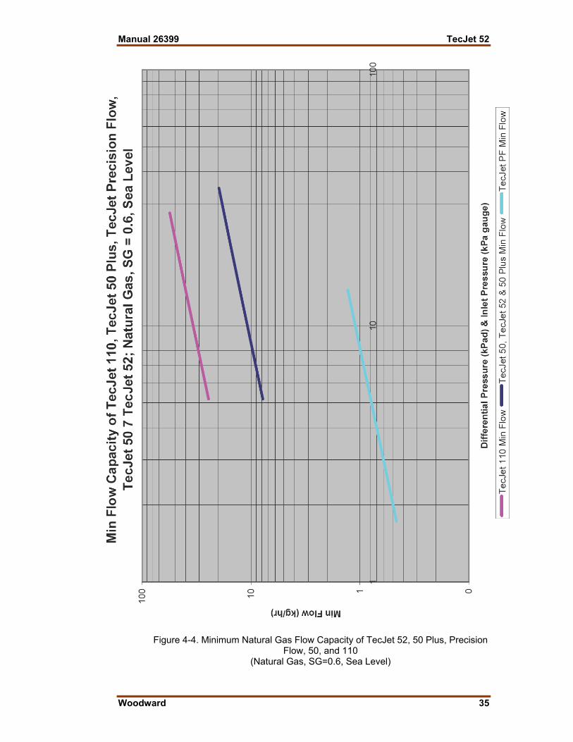
Figures 4-1 through 4-4 show the maximum and minimum amounts of gas that the TecJet™ 52 will flow as a function of pressure differential in kPa(d). Figures 4-1 and 4-2 indicate flow values for specialty gas, while Figures 4-3 and 4-4 indicate flow values for natural gas. Plots for the TecJet 110 and the TecJet 50 Plus are also shown for comparison purposes. Comparing the TecJet 52 vs Application Maximum Flow Rate Choose the correct graph depending on your application flow media. Determine the maximum flow rate for your application in a metric mass flow rate (kg/h). Increase this value by 15% to ensure that the TecJet 52 will handle the maximum flow requirement under all conditions. Find this increased flow value on the left-side Y-axis of the graph. Next, determine the approximate valve pressure drop at the actual maximum flow for your application. Locate this value on the X-axis of the graph. Metric [kPa(d)] units are provided. Note that the graphs assume the application outlet pressure is at sea level atmospheric pressure. Take the increased flow rate value and the pressure drop value, and determine where they cross on the graph. This is the maximum flow operating point for your application. This point should fall below the maximum flow plot for the valve in question. Comparing the TecJet 52 vs Application Minimum Flow Rate Choose the correct graph depending on your application flow media. Determine the minimum flow rate for your application in a metric mass flow rate (kg/h). Reduced this value by 10% to ensure that the TecJet 52 will handle the minimum flow requirement under all conditions. Find this reduced flow value on the right-side Y-axis of the graph. Next, determine the approximate valve pressure drop at the actual minimum flow for your application. Locate this value on the X-axis of the graph. Metric [kPa(d)] units are provided. Note that the graphs assume the application outlet pressure is at sea level atmospheric pressure. Take the reduced flow rate value and the pressure drop value, and determine where they cross on the graph. This is the minimum flow operating point for your application. This point should fall above the minimum flow plot for the valve in question.
TecJet 52 Manual 26399
32 Woodward
Figure 4-1. Maximum Specialty Gas Flow Capacity of TecJet 52, 50 Plus, Precision Flow, 50, and 110
(Specialty Gas, SG=1, Sea Level)

Manual 26399 TecJet 52
Woodward 33
Figure 4-2. Minimum Specialty Gas Flow Capacity of TecJet 52, 50 Plus, Precision Flow, 50, and 110
(Specialty Gas, SG=1, Sea Level)

TecJet 52 Manual 26399
34 Woodward
Figure 4-3. Maximum Natural Gas Flow Capacity of TecJet 52, 50 Plus, Precision
Flow, 50, and 110 (Natural Gas, SG=0.6, Sea Level)
Manual 26399 TecJet 52
Woodward 35
Figure 4-4. Minimum Natural Gas Flow Capacity of TecJet 52, 50 Plus, Precision
Flow, 50, and 110 (Natural Gas, SG=0.6, Sea Level)

TecJet 52 Manual 26399
36 Woodward
Chapter 5. Service Tool
Overview The Service Tool software is used to configure, setup, and troubleshoot the TecJet™ 52 control. This chapter describes the installation and use of the TecJet Service Tool and provides detailed instructions for configuring and setting up the TecJet 52 control for customer-specific applications.
NOTE Many TecJet 52 units are delivered pre-configured and calibrated with OEM specific settings. These units do not require the use of the Service Tool. However, the Service Tool is a valuable troubleshooting aid.
Description The TecJet Service Tool software resides on a PC (personal computer) and communicates to the TecJet 52 control via RS-232 connection. An external TTL to RS-232 transceiver (Woodward P/N 1249-1039) is needed to make possible communications with the Woodward TecJet Service Tool. This works best if it is wired into the harness within 18 inches (1 meter max) of the TecJet 52 control. A communication harness kit can also be purchased from Woodward (one each of Woodward P/N 1249-1120 and 1249-1039). See Figure 5-1 for the communication harness connections. The communication harness kit is a service port adaptor and is not intended to remain in the engine wiring harness during normal operation (only during engine setup). To use this adaptor, a 9-pin straight-through serial cable is needed between the harness transceiver RS-232 port and the PC. This serial cable must include ALL conductors. If it is limited to only pins 2, 3, and 5, it will not function correctly with the adaptor.
Installation The TecJet Service Tool is available at www.woodward.com/software. Select software product “TecJet Service Tool”. Follow the installation instructions given on that page.
CAUTION—SOFTWARE TOOLS An unsafe condition could occur with improper use of these software tools. Only trained personnel should have access to these tools.

Manual 26399 TecJet 52
Woodward 37
System Requirements The following hardware is required to work with the TecJet 52 control: • PC-compatible laptop or desktop computer
o Microsoft Windows® XP, 2000, NT 4.0 Service Pack 6a, Me, or 98 o 300 MHz Pentium® CPU o 64 MB of RAM o Minimum 800 by 600 pixel screen with 256 colors
• Serial Port • Serial Extension Cable • Communication/data link harness. What to do next After the software is installed, install the communication harness and connect a straight-through 9-pin serial communications cable between the converter RS-232 port and an unused serial port on your computer. Power must be applied to the TecJet 52 control for the Service Tool to connect. Run the Service Tool program and, when prompted, select an available com port. This will connect the Service Tool to the TecJet 52 control. Once connected to the control, the Overview screen (Figure 5-2) will open and populate with current values and the status bar will display ‘connected’. The TecJet 52 Demand Source and active Control Status messages are also displayed in an area common to all screens.
EngineControlHarness
To PC (loadedwith Service Tool)
9-Pin Straight-Thru Cable
TTL to RS 232 Converter(Woodward 1249-1039)
To TecJet 52Actuator
TTL 232
Communication Harness(Woodward 1249-1120)
Figure 5-1. Communication- Harness Connections
CAUTION—SERIAL PORT DAMAGE POTENTIAL There is a potential for serial port damage when communicating with the TecJet 52 control. This is caused by a difference in AC voltage between neutral and earth ground. If the PC RS-232 port ground is referenced to AC neutral, and the TecJet 52 control is referenced to battery ground (AC earth ground), a large amount of current can be experienced. To avoid this situation, we strongly recommend placing an isolation transformer between the AC outlet and the PC or run a laptop with the AC power disconnected.
TecJet 52 Manual 26399
38 Woodward
Service Tool Help Online Service Tool help is available and included with the installation of the Service Tool product. Help can be accessed from the Service Tool ‘Help’ menu located on the main screen Service Tool Security There are no password security levels provided by the TecJet Service Tool.
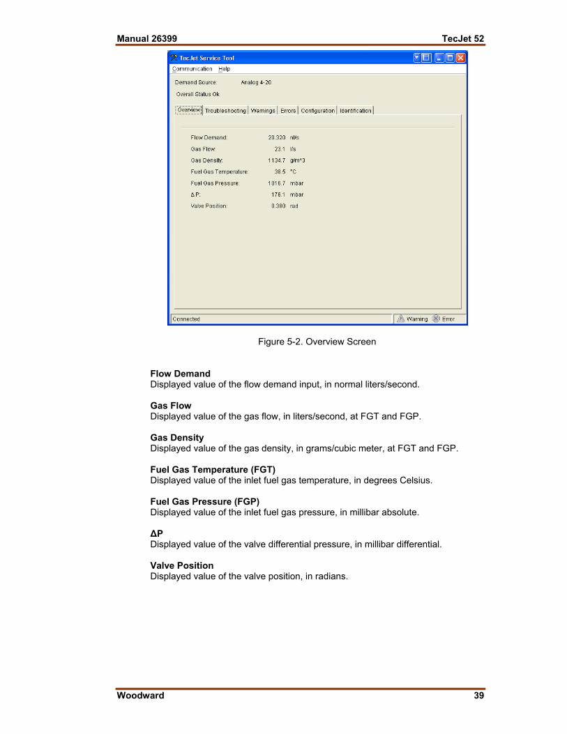
Troubleshooting the Driver The Service Tool has six (6) screens for troubleshooting driver parameters: • Overview (Figure 5-2) • Troubleshooting (Figure 5-3) • Warnings (Figure 5-4) • Errors (Figure 5-5) • Configuration (Figure 5-6) • Identification (Figure 5-7) Screen Navigation Service Tool screens can be selected for viewing by clicking the various tabs provided on the main and edit configuration screens. Overview Screen The Overview screen is the default screen that opens when connecting the TecJet Service Tool to the TecJet 52 control. The Overview screen displays TecJet 52 flow parameters and the valve position. The status bar, common to all screens, displays the communication, warning and error status. The triangular warning symbol turns yellow with a warning is active. The round error symbol turns red with an error is active.
Manual 26399 TecJet 52
Woodward 39
Figure 5-2. Overview Screen Flow Demand Displayed value of the flow demand input, in normal liters/second. Gas Flow Displayed value of the gas flow, in liters/second, at FGT and FGP. Gas Density Displayed value of the gas density, in grams/cubic meter, at FGT and FGP. Fuel Gas Temperature (FGT) Displayed value of the inlet fuel gas temperature, in degrees Celsius. Fuel Gas Pressure (FGP) Displayed value of the inlet fuel gas pressure, in millibar absolute. ΔP Displayed value of the valve differential pressure, in millibar differential. Valve Position Displayed value of the valve position, in radians.

TecJet 52 Manual 26399
40 Woodward
Troubleshooting Screen Select the Troubleshooting tab to view general TecJet 52 control parameters. This screen dynamically populates based on the TecJet 52 configuration. If a function is not programmed, then it will not appear. The analog configuration is shown here.
Figure 5-3. Troubleshooting Screen Electronics Temperature Displayed value of the electronics temperature sensor, in degrees Celsius. Coil Current Displayed value of the estimated actuator coil current, in amperes. Input Supply Displayed value of the input power, in volts. Running Hours Displayed value of the running hours. Reset Running Hours To reset the running hours to zero, click the ‘Reset Running Hours’ button. Keyswitch Input Status Displayed status of the keyswitch input. Value is active or inactive. PWM Frequency (PWM Demand Source Configuration Only) Displayed value of the PWM input frequency, in hertz.

Manual 26399 TecJet 52
Woodward 41
PWM Duty Cycle Displayed value of the PWM input duty cycle, in %. Analog Input Current (Analog Demand Source Configuration Only) Displayed value of the analog input, in milliamps. CAN Status Displayed value of the CAN status (e.g., error passive, stuff error, etc.) Reset CAN Status To clear the displayed CAN status, click the ‘Reset CAN Status’ button. CAN Id Displayed value of the CAN identification number. Value is 1, 2, 3 or 4. CAN Rx Error Count Displayed value of the CAN receive error counter. CAN Tx Error Count Displayed value of the CAN transmit error counter. Warnings Screen Select the Warnings tab to view TecJet 52 active or previously active warning conditions. Warnings indicate a problem has occurred that needs attention but the valve attempts continued operation. This screen dynamically populates based on the TecJet 52 configuration. If a function is not programmed, then it will not appear. A Reset Warnings button is provided to clear inactive warnings.
Figure 5-4. Warnings Screen

TecJet 52 Manual 26399
42 Woodward
NOTE Refer to Troubleshooting, Chapter 6, for a description of each displayed Warning plus possible causes and remedial actions. Errors Screen Select the Errors tab to view active TecJet 52 error conditions. Errors indicate a serious problem has occurred and the valve is not able to operate. This screen dynamically populates based on the TecJet 52 configuration. If a function is not programmed, then it will not appear.
Figure 5-5. Errors Screen Shutdown Indicates the valve is closed or attempting to close due to a detected error. Internal Fault Indicates an internal fault has occurred that prevents normal operation of the valve. ΔP Sensor High Indicates the Delta Pressure value has exceeded the delta pressure sensor's electrical high limit threshold. ΔP Sensor Low Indicates the Delta Pressure value has exceeded the delta pressure sensor's electrical low limit threshold.
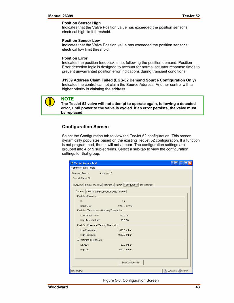
Manual 26399 TecJet 52
Woodward 43
Position Sensor High Indicates that the Valve Position value has exceeded the position sensor's electrical high limit threshold. Position Sensor Low Indicates that the Valve Position value has exceeded the position sensor's electrical low limit threshold. Position Error Indicates the position feedback is not following the position demand. Position Error detection logic is designed to account for normal actuator response times to prevent unwarranted position error indications during transient conditions. J1939 Address Claim Failed (EGS-02 Demand Source Configuration Only) Indicates the control cannot claim the Source Address. Another control with a higher priority is claiming the address.
NOTE The TecJet 52 valve will not attempt to operate again, following a detected error, until power to the valve is cycled. If an error persists, the valve must be replaced. Configuration Screen Select the Configuration tab to view the TecJet 52 configuration. This screen dynamically populates based on the existing TecJet 52 configuration. If a function is not programmed, then it will not appear. The configuration settings are grouped into 4 or 5 sub-screens. Select a sub-tab to view the configuration settings for that group.
Figure 5-6. Configuration Screen

TecJet 52 Manual 26399
44 Woodward
Identification Screen Select the Identification tab to view TecJet 52 identification information.
Figure 5-7. Identification Screen Software Part Number Displayed software part number and revision letter. Serial Number Displayed TecJet 52 valve serial number. Hardware Part Number Displayed TecJet 52 valve part number and revision letter.
Configuring the Driver The Service Tool has six (6) screens for editing the driver configuration: • Edit TecJet Configuration, Demand Source (Figure 5-8) • Edit TecJet Configuration, General (Figure 5-9) • Edit TecJet Configuration, Flow (Figure 5-10a, 10b, 10c) • Edit TecJet Configuration, Failed Sensor Defaults (Figure 5-11) • Edit TecJet Configuration, Filters (Figure 5-12) • Edit TecJet Configuration, CAN (Figure 5-13a, 13b)
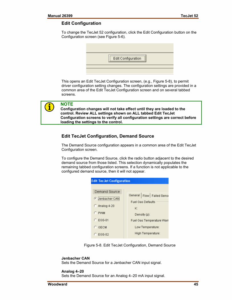
Manual 26399 TecJet 52
Woodward 45
Edit Configuration To change the TecJet 52 configuration, click the Edit Configuration button on the Configuration screen (see Figure 5-6).
This opens an Edit TecJet Configuration screen, (e.g., Figure 5-8), to permit driver configuration setting changes. The configuration settings are provided in a common area of the Edit TecJet Configuration screen and on several tabbed screens.
NOTE Configuration changes will not take effect until they are loaded to the control. Review ALL settings shown on ALL tabbed Edit TecJet Configuration screens to verify all configuration settings are correct before loading the settings to the control. Edit TecJet Configuration, Demand Source The Demand Source configuration appears in a common area of the Edit TecJet Configuration screen. To configure the Demand Source, click the radio button adjacent to the desired demand source from those listed. This selection dynamically populates the remaining tabbed configuration screens. If a function is not applicable to the configured demand source, then it will not appear.
Figure 5-8. Edit TecJet Configuration, Demand Source Jenbacher CAN Sets the Demand Source for a Jenbacher CAN input signal. Analog 4–20 Sets the Demand Source for an Analog 4–20 mA input signal.
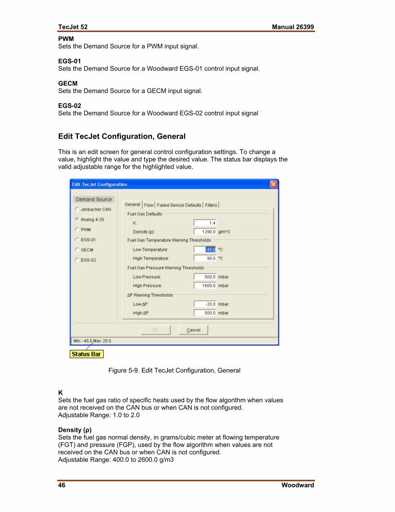
TecJet 52 Manual 26399
46 Woodward
PWM Sets the Demand Source for a PWM input signal. EGS-01 Sets the Demand Source for a Woodward EGS-01 control input signal. GECM Sets the Demand Source for a GECM input signal. EGS-02 Sets the Demand Source for a Woodward EGS-02 control input signal Edit TecJet Configuration, General This is an edit screen for general control configuration settings. To change a value, highlight the value and type the desired value. The status bar displays the valid adjustable range for the highlighted value.
Figure 5-9. Edit TecJet Configuration, General K Sets the fuel gas ratio of specific heats used by the flow algorithm when values are not received on the CAN bus or when CAN is not configured. Adjustable Range: 1.0 to 2.0 Density (ρ) Sets the fuel gas normal density, in grams/cubic meter at flowing temperature (FGT) and pressure (FGP), used by the flow algorithm when values are not received on the CAN bus or when CAN is not configured. Adjustable Range: 400.0 to 2600.0 g/m3
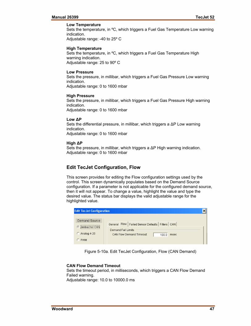
Manual 26399 TecJet 52
Woodward 47
Low Temperature Sets the temperature, in ºC, which triggers a Fuel Gas Temperature Low warning indication. Adjustable range: -40 to 25º C High Temperature Sets the temperature, in ºC, which triggers a Fuel Gas Temperature High warning indication. Adjustable range: 25 to 90º C Low Pressure Sets the pressure, in millibar, which triggers a Fuel Gas Pressure Low warning indication. Adjustable range: 0 to 1600 mbar High Pressure Sets the pressure, in millibar, which triggers a Fuel Gas Pressure High warning indication. Adjustable range: 0 to 1600 mbar Low ΔP Sets the differential pressure, in millibar, which triggers a ΔP Low warning indication. Adjustable range: 0 to 1600 mbar High ΔP Sets the pressure, in millibar, which triggers a ΔP High warning indication. Adjustable range: 0 to 1600 mbar Edit TecJet Configuration, Flow This screen provides for editing the Flow configuration settings used by the control. This screen dynamically populates based on the Demand Source configuration. If a parameter is not applicable for the configured demand source, then it will not appear. To change a value, highlight the value and type the desired value. The status bar displays the valid adjustable range for the highlighted value.
Figure 5-10a. Edit TecJet Configuration, Flow (CAN Demand) CAN Flow Demand Timeout Sets the timeout period, in milliseconds, which triggers a CAN Flow Demand Failed warning. Adjustable range: 10.0 to 10000.0 ms

TecJet 52 Manual 26399
48 Woodward
Figure 5-10b. Edit TecJet Configuration, Flow (Analog Demand) Analog Input Minimum Sets the current, in milliamps, which triggers an Analog Flow Demand Low warning. Adjustable range: 0–22 mA Analog Input Maximum Sets the current, in milliamps, which triggers an Analog Flow Demand High warning. Adjustable range: 0–22 mA Scaling Sets the low and high values for scaling the analog demand source versus fuel flow. The current range set by the scaling/low/current and scaling/high/current settings will cause the TecJet 52 valve to deliver the corresponding fuel flow set by the scaling/low/flow and scaling/high/flow settings. Intermediate values are linear with between these low and high settings. • Scaling, Current, Low Sets the current, in milliamps, which corresponds to the Low Flow setting. Adjustable range: 3-22 mA • Scaling, Current, High Sets the current, in milliamps, which corresponds to the High Flow setting. Adjustable range: 3-22 mA • Scaling, Flow, Low Sets the flow, in normal liters/second, for the corresponding Low Current
setting. Adjustable range: 0–2000 Nl/s • Scaling, Flow, High Sets the flow, in normal liters/second, for the corresponding High Current
setting. Adjustable range: 0–2000 Nl/s

Manual 26399 TecJet 52
Woodward 49
Figure 5-10c. Edit TecJet Configuration, Flow (PWM Demand) PWM Duty Cycle Minimum Sets the PWM duty cycle, in percent, which triggers a PWM Flow Demand Low warning. Adjustable range: 2-50 % PWM Duty Cycle Maximum Sets the PWM duty cycle, in percent, which triggers a PWM Flow Demand High warning. Adjustable range: 50–98% Scaling Sets the low and high values for scaling the PWM demand source versus fuel flow. The duty cycle range set by the scaling/low/duty cycle and scaling/high/duty cycle settings will cause the TecJet 52 valve to deliver the corresponding fuel flow set by the scaling/low/flow and scaling/high/flow settings. Intermediate values are linear with between these low and high settings. • Scaling, Duty Cycle, Low Sets the PWM duty cycle, which corresponds to the Low Flow setting. Adjustable range: 5-95 % • Scaling, Duty Cycle, High Sets the PWM duty cycle, which corresponds to the High Flow setting. Adjustable range: 5-95 % • Scaling, Flow, Low Sets the flow, in normal liters/second, for the corresponding Low Duty Cycle
setting. Adjustable range: 0–2000 Nl/s • Scaling, Flow, High Sets the flow, in normal liters/second, for the corresponding High Duty Cycle
setting. Adjustable range: 0–2000 Nl/s

TecJet 52 Manual 26399
50 Woodward
Edit TecJet Configuration, Failed Sensor Defaults This screen provides for editing the Failed Sensor Default configuration settings used by the control in the event a sensor input fails. To change a value, highlight the value and type the desired value. The status bar displays the valid adjustable range for the highlighted value.
Figure 5-11. Edit TecJet Configuration, Failed Sensor Defaults Default Temperature Sets the temperature, in °C, the control will use to continue operation upon failure of the fuel gas temperature sensor. Adjustable range: 0 to 60 °C Default Downstream Pressure This sets an estimated pressure, in millibar absolute, that the control will use to continue operation upon failure of the fuel gas pressure sensor. Estimate is based on a 4-point curve of the flow demand, in normal liters/second, versus default downstream pressure, in millibar absolute. (Estimated FGP = Default Downstream Pressure + ΔP). • Flow Demand [1-4] Sets the flow demand [1-4], in normal liters/second, which corresponds to
the default downstream pressure setting. Adjustable range: 0–2000 Nl/s • FGP- ΔP [1-4] Sets the default downstream pressure [1-4], in mbar abs, for the
corresponding flow demand [1-4] settings. Adjustable range: 0–2000 mbar abs

Manual 26399 TecJet 52
Woodward 51
Edit TecJet Configuration, Filters This screen provides for editing various input signal filter configuration settings. To change a value, highlight the value and type the desired value. The status bar displays the valid adjustable range for the highlighted value. The filters are provided for system troubleshooting purposes, and should be set to 0 in normal applications.
Figure 5-12. Edit TecJet Configuration, Filters ΔP Filter Time Constant Sets the Delta P sensor time constant. There is a single-pole lag between the delta P sensor and the flow algorithm. Adjustable range: 0 to 5 sec Fuel Gas Pressure Filter Time Constant Sets the Fuel Gas Pressure sensor time constant. There is a single-pole lag between the fuel gas pressure sensor and the flow algorithm. Adjustable range: 0 to 5 sec Fuel Gas Temperature Filter Time Constant Sets the Fuel Gas Temperature sensor time constant. There is a single-pole lag between the fuel gas temperature sensor and the flow algorithm. Adjustable range: 0 to 5 sec Flow Demand Filter Time Constant Sets the Flow Demand time constant. There is a single-pole lag between the flow demand value and the flow algorithm. Adjustable range: 0 to 5 sec

TecJet 52 Manual 26399
52 Woodward
Edit TecJet Configuration, CAN This screen provides for editing CAN communication configuration settings. To select a ‘Default’ or ‘User Configured’ baud rate, click the radio button adjacent to the each choice.
Figure 5-13a. Edit TecJet Configuration, CAN (Default) Baud Rate, Default Sets the default baud rate of the CAN communication in kbps. Adjustable range: 10, 50, 100, 125, 250, 500, or 1000 kbps.
Figure 5-13b. Edit TecJet Configuration, CAN (User Configured) Baud Rate, User Configured Provides user settings for more flexible control of the CAN parameters. This option should be used by advanced users only. The baud rate of the CAN communication is calculated from these settings as follows: Baud Rate = 40E6 / [(BRP + 1) x (TSEG1 + TSEG2 + 1)] • Baud Rate Prescaler (BRP) Sets the baud rate prescaler in the CAN controller. Adjustable range: 0–255 • TSEG01 Sets the Tseg1 value in the CAN controller. Tseg1 combines the
PROP_SEG and PHASE_SEG1 segments of the CAN protocol. Adjustable range: 3–16 • TSEG02 Sets the Tseg2 value in the CAN controller. Tseg2 defines the
PHASE_SEG2 segment of the CAN protocol. Adjustable range: 2–8 • Synchronization Jump Width Determines the synchronization jump width in the CAN controller. Adjustable range: 1–4
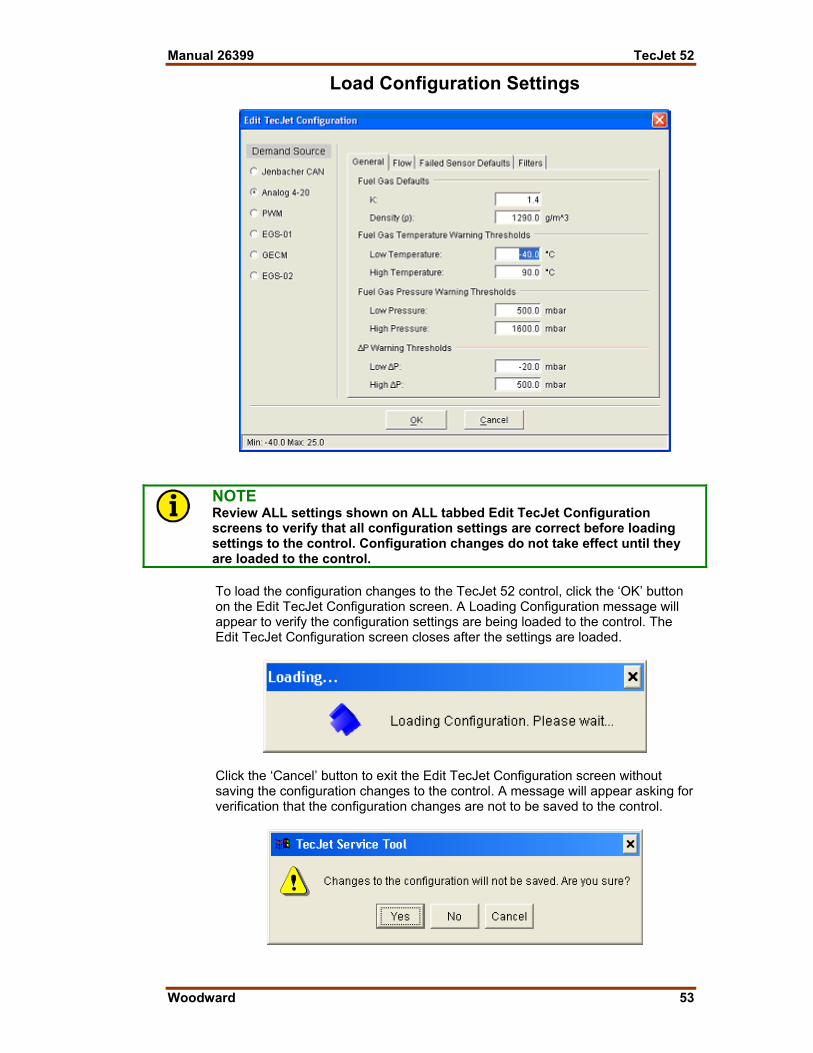
Manual 26399 TecJet 52
Woodward 53
Load Configuration Settings
NOTE Review ALL settings shown on ALL tabbed Edit TecJet Configuration screens to verify that all configuration settings are correct before loading settings to the control. Configuration changes do not take effect until they are loaded to the control. To load the configuration changes to the TecJet 52 control, click the ‘OK’ button on the Edit TecJet Configuration screen. A Loading Configuration message will appear to verify the configuration settings are being loaded to the control. The Edit TecJet Configuration screen closes after the settings are loaded.
Click the ‘Cancel’ button to exit the Edit TecJet Configuration screen without saving the configuration changes to the control. A message will appear asking for verification that the configuration changes are not to be saved to the control.
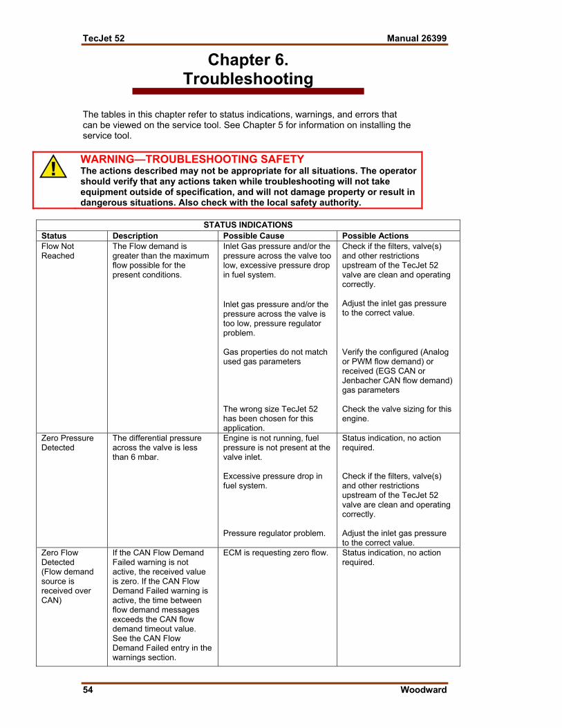
TecJet 52 Manual 26399
54 Woodward
Chapter 6. Troubleshooting
The tables in this chapter refer to status indications, warnings, and errors that can be viewed on the service tool. See Chapter 5 for information on installing the service tool.
WARNING—TROUBLESHOOTING SAFETY The actions described may not be appropriate for all situations. The operator should verify that any actions taken while troubleshooting will not take equipment outside of specification, and will not damage property or result in dangerous situations. Also check with the local safety authority.
STATUS INDICATIONSStatus Description Possible Cause Possible Actions Flow Not Reached
The Flow demand is greater than the maximum flow possible for the present conditions.
Inlet Gas pressure and/or the pressure across the valve too low, excessive pressure drop in fuel system. Inlet gas pressure and/or the pressure across the valve is too low, pressure regulator problem. Gas properties do not match used gas parameters The wrong size TecJet 52 has been chosen for this application.
Check if the filters, valve(s) and other restrictions upstream of the TecJet 52 valve are clean and operating correctly. Adjust the inlet gas pressure to the correct value. Verify the configured (Analog or PWM flow demand) or received (EGS CAN or Jenbacher CAN flow demand) gas parameters Check the valve sizing for this engine.
Zero Pressure Detected
The differential pressure across the valve is less than 6 mbar.
Engine is not running, fuel pressure is not present at the valve inlet. Excessive pressure drop in fuel system. Pressure regulator problem.
Status indication, no action required. Check if the filters, valve(s) and other restrictions upstream of the TecJet 52 valve are clean and operating correctly. Adjust the inlet gas pressure to the correct value.
Zero Flow Detected (Flow demand source is received over CAN)
If the CAN Flow Demand Failed warning is not active, the received value is zero. If the CAN Flow Demand Failed warning is active, the time between flow demand messages exceeds the CAN flow demand timeout value. See the CAN Flow Demand Failed entry in the warnings section.
ECM is requesting zero flow. Status indication, no action required.

Manual 26399 TecJet 52
Woodward 55
STATUS INDICATIONSStatus Description Possible Cause Possible ActionsZero Flow Detected (Flow demand source is PWM)
If the PWM flow demand high/low warnings are not active, the flow demand is zero. If the PWM Flow Demand High or PWM Flow Demand Low warning is active, the flow demand is out of range. See the corresponding entries in the warnings section.
ECM is requesting zero flow. Status indication, no action required.
Zero Flow Detected (Flow demand source is Analog 4–20)
If the Analog Flow Demand Low/High warnings are not active, the flow demand is zero. If the Analog Flow Demand Low or Analog Flow Demand High warning is active, the flow demand is out of range. See the corresponding entries in the warnings section.
ECM is requesting zero flow. Status indication, no action required.
WARNINGSWarning Description Possible Cause Possible ActionsAnalog Flow Demand High
The analog flow demand exceeds the analog flow demand maximum fail limit.
Analog input wiring problem. Analog input current is out of range.
Check the analog input wiring for shorts, open connections and intermitted contacts. Ensure that the analog input signal is within the configured range. The service tool displays the analog input current and the range limits.
Analog Flow Demand Low
The analog flow demand is below the analog flow demand minimum fail limit.
Analog input wiring problem. Analog input current is out of range.
Check the analog input wiring for shorts, open connections and intermitted contacts. Ensure that the analog input signal is within the configured range. The service tool displays the analog input current and the range limits.

TecJet 52 Manual 26399
56 Woodward
WARNINGSWarning Description Possible Cause Possible Actions CAN Flow Demand Failed
The CAN flow demand is not being received. The time between messages must be less than the CAN flow demand timeout value.
Incorrect TecJet 52 Number. ECM is not sending Qgn messages, or is not sending messages to the correct TecJet 52 number. CAN termination problem. CAN wiring problem. CAN noise problem. CANbus incompatibility with ECM, e.g., baud rate. CAN traffic overload.
Check the CAN ID inputs to the valve. Verify that the ECM is powered up and sending valid Qgn messages, and that the correct TecJet 52 ID numbers are selected. Check if the CANbus has the right termination resistor connected at both ends of the bus. Check the CAN wiring for shorts, open connections, interchanged connections, and intermittent contacts. Verify that the CAN wiring is installed according to the installation instruction Verify ECM CANbus compatibility. Verify that there is not excessive CAN traffic that has higher priority than the TecJet 52 flow demand message.
Delta P High The Delta Pressure value exceeds the delta pressure high warning threshold.
Warning threshold improperly configured. Pressure regulator adjusted too high.
Configure warning threshold for value appropriate to the application. Adjust pressure regulator.
Delta P Low The Delta Pressure value is below the delta pressure low warning threshold.
Warning threshold improperly configured. Valve is installed backwards.
Configure warning threshold for value appropriate to the application. Verify that gas flow is in the direction of the arrow on the valve.
Electrical Temperature High
The valve internal temperature has risen too high to allow full-power operation. The torque available to move the valve is reduced and the valve may not meet specified performance levels.
Valve ambient temperature is too high. Internal fault.
Reduce ambient temperature. Replace the valve.
Electronics Temperature High
The internal electronics temperature sensor has failed to a high value. The valve may not reach specified performance.
Internal fault. Replace the valve.
Electronics Temperature Low
The internal electronics temperature sensor has failed to a low value. The valve may not reach specified performance.
Internal fault. Replace the valve.

Manual 26399 TecJet 52
Woodward 57
WARNINGSWarning Description Possible Cause Possible ActionsFuel Gas Pressure High
The Fuel Gas Pressure value exceeds the fuel gas pressure high warning threshold.
Warning threshold improperly configured. Pressure regulator adjusted too high. Faulty or slow pressure regulator.
Configure warning threshold for value appropriate to the application. Adjust pressure regulator. Verify proper pressure regulator operation.
Fuel Gas Pressure Low
The Fuel Gas Pressure value is below the fuel gas pressure low warning threshold.
Warning threshold improperly configured. Improper engine shutdown sequence.
Configure warning threshold for value appropriate to the application and the elevation of the site. Verify proper engine shutdown sequence.
Fuel Gas Pressure Sensor High
The Fuel Gas Pressure sensor has failed to a high value. The fuel gas pressure value is derived from the default downstream pressure table instead.
Internal fault. Replace valve.
Fuel Gas Pressure Sensor Low
The Fuel Gas Pressure sensor has failed to a low value. The fuel gas pressure value is derived from the default downstream pressure table instead.
Internal fault. Replace valve.
Fuel Gas Temperature High
The Fuel Gas Temperature value exceeds the fuel gas temperature high warning threshold.
Warning threshold improperly configured. Fuel temperature is above warning threshold.
Configure warning threshold for value appropriate to the application. Correct fuel temperature problem.
Fuel Gas Temperature Low
The Fuel Gas Temperature value is below the fuel gas temperature low warning threshold.
Warning threshold improperly configured. Fuel temperature is below warning threshold.
Configure warning threshold for value appropriate to the application. Correct fuel temperature problem.
Fuel Gas Temperature Sensor High
The Fuel Gas Temperature sensor has failed to a high value and the default fuel gas temperature is being used instead.
Internal fault. Replace valve.
Fuel Gas Temperature Sensor Low
The Fuel Gas Temperature sensor has failed to a low value and the default fuel gas temperature is being used instead.
Internal fault. Replace valve.
Input Voltage High
The battery voltage seen by the valve is above the limit specified in the manual.
Faulty battery or supply. Faulty or no battery charger. Improper wiring.
Check battery or supply for correct operation. Check battery charger for correct operation. Check wiring for correct size, length, contacts, fuses.

TecJet 52 Manual 26399
58 Woodward
WARNINGSWarning Description Possible Cause Possible Actions Input Voltage Low
The battery voltage seen by the valve is below the limit specified in the manual.
Faulty battery or supply. Faulty or no battery charger. Improper wiring.
Check battery or supply for correct operation. Check battery charger for correct operation. Check wiring for correct size, length, contacts, fuses.
PWM Flow Demand High
The PWM flow demand exceeds the PWM flow demand maximum duty cycle fail limit.
PWM wiring problem. PWM frequency is out of range. PWM duty cycle is out of range.
Check the PWM input wiring for shorts, open connections and intermitted contacts. Verify that the PWM frequency from the ECM is within specified limits. Ensure that the PWM signal is within the configured range. The service tool displays the PWM frequency, duty cycle, and range limits.
PWM Flow Demand Low
The PWM flow demand is below the PWM flow demand minimum duty cycle fail limit.
PWM wiring problem. PWM frequency is out of range. PWM duty cycle is out of range.
Check the PWM input wiring for shorts, open connections and intermitted contacts. Verify that the PWM frequency from the ECM is within specified limits. Ensure that the PWM signal is within the configured range. The service tool displays the PWM frequency, duty cycle, and range limits.
ERRORSWhen an error occurs, the valve closes, if possible. It will not attempt to operate again until power to the valve is cycled. If the error persists, the valve must be replaced. Error DescriptionShutdown One or more of the errors below is active. Internal Error The valve has detected an internal error that prevents it from
operating. Delta P Sensor High The delta P sensor has failed to a high value. Delta P Sensor Low The delta P sensor has failed to a low value. Position Sensor High The position sensor has failed to a high value. Position Sensor Low The position sensor has failed to a low value. Position Error The actuator was not able to position the valve properly. J1939 Address Claim Failed The control cannot claim the Source Address. Another control with
a higher priority is claiming the address.

Manual 26399 TecJet 52
Woodward 59
Chapter 7. Maintenance
General Build-up of deposits near the metering area of the TecJet™ 52 can develop depending on the quality of the gas being metered. This build-up can affect the performance of the TecJet 52 and may appear as degradation of actual flow vs command flow accuracy, or as flow control instability.
Limits of Applicability Periodic cleaning may be performed and needed to ensure the best operation of the TecJet 52. It is the customer’s responsibility to monitor the need for valid scheduled maintenance, as this will vary depending on the quality of the gas in the particular application. The procedure below has been tested and validated for a particular gas environment (mineral deposits); the applicability to other gaseous environment needs to be validated by the OEM at the customer site.
Cleaning Procedure When cleaning the metering element and the inside of the valve body, do not use sharp objects that may scrape or dent the metering elements, as this could degrade the accuracy of the valve. Any damage to the internal geometry of the TecJet 52, especially the valve plate or bore area around the valve plate, will change the calibration of the valve and void the warranty. High pressure washing is not recommended. There are no components of the TecJet 52 that are replaceable or serviceable. Make sure that the power is disconnected before removing the TecJet 52 main connector. A petrochemical solvent is recommended to clean (wash and brush) the valve when minimal film/patina build up is observed. In applications where solids (mineral deposits) are found in the gas, the following procedure should be used (this procedure can be performed at the site): • Position the TecJet 52 in the fully open position. • Place a plugged piece of tubing over the P1 probe to completely seal the
probe. • Place a plug in the P2 port to completely seal it. • Cap/seal the inlet flange of the TecJet 52. • Fill the TecJet 52 with a solution of 60 °C water and 2 tablespoons of Dawn
(or equivalent) dishwashing detergent. • Cap/seal the outlet flange of the TecJet 52. • Leave soap solution in the TecJet 52 for 24 to 30 hours. • Remove the cap/seal on the outlet flange of the TecJet 52. • Dump the soap solution out of TecJet 52. • Fill the TecJet 52 with fresh 60 °C tap water and move the water around in
the valve bore with a long plastic rod or equivalent. • Dump the rinse water out of the TecJet 52.
TecJet 52 Manual 26399
60 Woodward
• Fill the TecJet 52 again with fresh 60 °C tap water and move the water around in the valve bore with a long plastic rod or equivalent.
• Dump the rinse water out of the TecJet 52. • Remove the cap/seal on the inlet flange of the TecJet 52. • Inspect the valve plate and bore area around the valve plate for any
remaining contamination. • Use a soft plastic brush, or equivalent, to gently remove any remaining
contamination and rinse with tap water as necessary. • Remove the tubing from the P1 probe. • Remove the plug from the P2 port. • Leave the valve bore open to air until completely dry. • If contamination has been successfully removed, return the valve to service. • If contamination still exists on the valve plate and/or bore area around the
valve plate, the unit will need to be replaced with a new unit.

Manual 26399 TecJet 52
Woodward 61
Chapter 8. Service Options
Product Service Options The following factory options are available for servicing Woodward equipment, based on the standard Woodward Product and Service Warranty (5-01-1205) that is in effect at the time the product is purchased from Woodward or the service is performed: • Replacement/Exchange (24-hour service) • Flat Rate Repair • Flat Rate Remanufacture If you are experiencing problems with installation or unsatisfactory performance of an installed system, the following options are available: • Consult the troubleshooting guide in the manual. • Contact Woodward technical assistance (see “How to Contact Woodward”
later in this chapter) and discuss your problem. In most cases, your problem can be resolved over the phone. If not, you can select which course of action you wish to pursue based on the available services listed in this section.
Replacement/Exchange Replacement/Exchange is a premium program designed for the user who is in need of immediate service. It allows you to request and receive a like-new replacement unit in minimum time (usually within 24 hours of the request), providing a suitable unit is available at the time of the request, thereby minimizing costly downtime. This is also a flat rate structured program and includes the full standard Woodward product warranty (Woodward Product and Service Warranty 5-01-1205). This option allows you to call in the event of an unexpected outage, or in advance of a scheduled outage, to request a replacement control unit. If the unit is available at the time of the call, it can usually be shipped out within 24 hours. You replace your field control unit with the like-new replacement and return the field unit to the Woodward facility as explained below (see “Returning Equipment for Repair” later in this chapter). Charges for the Replacement/Exchange service are based on a flat rate plus shipping expenses. You are invoiced the flat rate replacement/exchange charge plus a core charge at the time the replacement unit is shipped. If the core (field unit) is returned to Woodward within 60 days, Woodward will issue a credit for the core charge. [The core charge is the average difference between the flat rate replacement/exchange charge and the current list price of a new unit.] Return Shipment Authorization Label. To ensure prompt receipt of the core, and avoid additional charges, the package must be properly marked. A return authorization label is included with every Replacement/Exchange unit that leaves Woodward. The core should be repackaged and the return authorization label affixed to the outside of the package. Without the authorization label, receipt of the returned core could be delayed and cause additional charges to be applied.

TecJet 52 Manual 26399
62 Woodward
Flat Rate Repair Flat Rate Repair is available for the majority of standard products in the field. This program offers you repair service for your products with the advantage of knowing in advance what the cost will be. All repair work carries the standard Woodward service warranty (Woodward Product and Service Warranty 5-01-1205) on replaced parts and labor. Flat Rate Remanufacture Flat Rate Remanufacture is very similar to the Flat Rate Repair option with the exception that the unit will be returned to you in “like-new” condition and carry with it the full standard Woodward product warranty (Woodward Product and Service Warranty 5-01-1205). This option is applicable to mechanical products only.
Returning Equipment for Repair If a control (or any part of an electronic control) is to be returned to Woodward for repair, please contact Woodward in advance to obtain a Return Authorization Number. When shipping the item(s), attach a tag with the following information: • Name and location where the control is installed • Name and phone number of contact person • Complete Woodward part number(s) and serial number(s) • Description of the problem • Instructions describing the desired type of repair
CAUTION—ELECTROSTATIC DISCHARGE To prevent damage to electronic components caused by improper handling, read and observe the precautions in Woodward manual 82715, Guide for Handling and Protection of Electronic Controls, Printed Circuit Boards, and Modules. Packing a Control Use the following materials when returning a complete control: • Protective caps on any connectors • Antistatic protective bags on all electronic modules • Packing materials that will not damage the surface of the unit • At least 100 mm (4 inches) of tightly packed, industry-approved packing
material • A packing carton with double walls • A strong tape around the outside of the carton for increased strength

Manual 26399 TecJet 52
Woodward 63
Return Authorization Number When returning equipment to Woodward, please telephone and ask for the Customer Service Department [1 (800) 523-2831 in North America or +1 (970) 482-5811]. They will help expedite the processing of your order through our distributors or local service facility. To expedite the repair process, contact Woodward in advance to obtain a Return Authorization Number, and arrange for issue of a purchase order for the item(s) to be repaired. No work can be started until a purchase order is received.
NOTE We highly recommend that you make arrangement in advance for return shipments. Contact a Woodward customer service representative at 1 (800) 523-2831 in North America or +1 (970) 482-5811 for instructions and for a Return Authorization Number.
Replacement Parts When ordering replacement parts for controls, include the following information: • The part number(s) (XXXX-XXXX) that is on the enclosure nameplate • The unit serial number, which is also on the nameplate
How to Contact Woodward In North America use the following address when shipping or corresponding: Woodward Governor Company PO Box 1519 1000 East Drake Rd Fort Collins CO 80522-1519, USA Telephone—+1 (970) 482-5811 (24 hours a day) Toll-free Phone (in North America)—1 (800) 523-2831 Fax—+1 (970) 498-3058 For assistance outside North America, call one of the following international Woodward facilities to obtain the address and phone number of the facility nearest your location where you will be able to get information and service. Facility Phone Number Brazil +55 (19) 3708 4800 India +91 (129) 4097100 Japan +81 (476) 93-4661 The Netherlands +31 (23) 5661111 You can also contact the Woodward Customer Service Department or consult our worldwide directory on Woodward’s website (www.woodward.com) for the name of your nearest Woodward distributor or service facility.

TecJet 52 Manual 26399
64 Woodward
Engineering Services Woodward Industrial Controls Engineering Services offers the following after-sales support for Woodward products. For these services, you can contact us by telephone, by email, or through the Woodward website. • Technical Support • Product Training • Field Service Contact information: Telephone—+1 (970) 482-5811 Toll-free Phone (in North America)—1 (800) 523-2831 Email—[email protected] Website—www.woodward.com Technical Support is available through our many worldwide locations or our authorized distributors, depending upon the product. This service can assist you with technical questions or problem solving during normal business hours. Emergency assistance is also available during non-business hours by phoning our toll-free number and stating the urgency of your problem. For technical support, please contact us via telephone, email us, or use our website and reference Customer Services and then Technical Support. Product Training is available at many of our worldwide locations (standard classes). We also offer customized classes, which can be tailored to your needs and can be held at one of our locations or at your site. This training, conducted by experienced personnel, will assure that you will be able to maintain system reliability and availability. For information concerning training, please contact us via telephone, email us, or use our website and reference Customer Services and then Product Training. Field Service engineering on-site support is available, depending on the product and location, from one of our many worldwide locations or from one of our authorized distributors. The field engineers are experienced both on Woodward products as well as on much of the non-Woodward equipment with which our products interface. For field service engineering assistance, please contact us via telephone, email us, or use our website and reference Customer Services and then Technical Support.
Manual 26399 TecJet 52
Woodward 65
Technical Assistance If you need to telephone for technical assistance, you will need to provide the following information. Please write it down here before phoning: General Your Name Site Location Phone Number Fax Number Prime Mover Information Engine/Turbine Model Number Manufacturer Number of Cylinders (if applicable) Type of Fuel (gas, gaseous, steam, etc) Rating Application Control/Governor Information Please list all Woodward governors, actuators, and electronic controls in your system: Woodward Part Number and Revision Letter Control Description or Governor Type Serial Number Woodward Part Number and Revision Letter Control Description or Governor Type Serial Number Woodward Part Number and Revision Letter Control Description or Governor Type Serial Number If you have an electronic or programmable control, please have the adjustment setting positions or the menu settings written down and with you at the time of the call.

We appreciate your comments about the content of our publications.
Send comments to: [email protected]
Please include the manual number from the front cover of this publication.
PO Box 1519, Fort Collins CO 80522-1519, USA 1000 East Drake Road, Fort Collins CO 80525, USA Phone +1 (970) 482-5811 • Fax +1 (970) 498-3058
Email and Website—www.woodward.com
Woodward has company-owned plants, subsidiaries, and branches, as well as authorized distributors and other authorized service and sales facilities throughout the world.
Complete address / phone / fax / email information for all locations is available on our website.
2008/5/Fort Collins