tee 2/b sonic percussion effects
TRANSCRIPT

tee
SONIC PERCUSSION
EFFECTS
2/B
# ••
llTF^
VVHgg^
& ^ IVIIC
INP^T
y •Cj.^
m t'i
wm
K£§o-
HIS ISSUE,
m m liljlVilfilU'il
LI?1 1 s IMALL CRAFT
TRANSISTOR CURVE TRACER
i

tPRQDUCTS L[ M If E D J tfiegd Trade Mark)
SOLDERING EQUIPMENT
ike
DISCRIMINATING
ENTHUSIAST
m
xv;.
f m
ILLUSTRATED: L64 -is" BIT INSTRUMENT IN L700 PROTECTIVE SHIELD
APPLY DIRECT TO: SALES & SERVICE DEPT. ADCOLA PRODUCTS LTD. ADCOLA HOUSE GAUDEN ROAD LONDON, S.W.4 TELEPHONE 01-622 0291
THIS IS WHAT
ABOUT BOOKS BY 0. A. 6RI60S IN
HIGH FIDELITY MAGAIIHE U.S.A. JANUARY 1968
Is there any reason why audio books can't be written in high style? G. A. Briggs has been doing it ever since High Fidelity first emerged from the exclusive domain of engineers and began to be cultivated by the cultivated. Consider his temerity in opening a chapter on distortion in his classic Sound Rcproduction with a quotation from Milton: ., dire was the noise of conflict". Or recall his wit in replying to a letter from a man who asked why "the body missing" from the sound when he put a back on his home-made speaker enclosure, and why the speaker sounded better when he took the back off again. Briggs wrote "... when you leave off the back . . . you obtain .. . reflection from the wall . . . use the system which
l sounds best, even if contrary to every textbook. In any case, as the I body has disappeared, there would not be much point in screwing Idowa the lid of the coffin."
Nojipdy else writes them with quite that flair. The BRIGGS books listed below are still
obtainable.
AERIAL HANDBOOK (second edition) 176 pages, 144 illustrations Price (semi-stiff cover) 15/- (16/- post free) ^
(cloth bound) 22/6 (24/- post free) CABINET HANDBOOK 112 pages, 90 illustrations \> Price 7/6 (8/6 post free) AUDIO BIOGRAPHIES 344 pages, 64 contributions from pioneers 1 and leaders in Audio. Cloth bound Price 25/- (26/6 post free) MUSICAL INSTRUMENTS AND AUDIO 240 pages, 212 illustrations. Cloth bound Price 32/6 (34/- post free) LOUDSPEAKERS Fifth edition—336 pages, 230 illustrations, Cloth bound Price 25/- (26/6 post free) A TO Z IN AUDIO 224 pages, 160 illustrations. Cloth bound Price 15/6 (17/- post free) MORE ABOUT LOUDSPEAKERS 136 pages, 112 illustrations Price 8/6 (9/6 post free) PIANOS, PIANISTS AND SONICS 190 pages, 102 illustrations. Cloth bound Price 18/6 (20/- post free) AUDIO AND ACOUSTICS 168 pages, 140 illustrations Price 12/6 (13/6 post free) 10^
ABOUT YOUR HEARING 132 pages, 112 illustrations Price (semi-stiff cover) 15/6 (16/6 post free) ' Cloth bound 22/6 (24/- post free)
^ • V/
Sold by Radio Dtolers and Book Shops or in case of difficulty direct from the Publishers
RANK WHARFEDALE LTD. IDLE, BRADFORD, YORKS. Tel.: Bradford 612552

Build Your Own Heathkit Electronics
A kit for every interest — Home Workshop — Hi-Fi — Radio — Test — Amateur
Latest STEREO TAPE RECORDER, STR-1 Fully portable—own speakers Kit £45.18.0
FOR THIS SPECIFICATION j track stereo or mono record and playback at 7}f3| and IJips. Sound- on-sound and sound-with-sound capabilities. Stereo record, stereo playback, mono record and playback
on either channel, 18 transistor circuit for cool, instant and depend- able operation. Moving coil record level indicator. Digital counter with thumb-wheel zero reset. Stereo microphone and auxiliary inputs and controls, speaker/headphone and external amplifier outputs... front panel mounted for easy access. Push-button controls for operational modes. Built-in stereo power amplifier giving 4W rms per channel. Two high efficiency 8' x 5' speakers. Operates on 230V a.c. supply. Versatile recording facilities. So easy to build—so easy to use.
Latest STEREO AMPLIFIER, TSA-12 12 x 12 watts output Kit £30.10.0 less cabinet
Cabinet £2.5.0 extra FOR THIS SPECIFICATION 17 transistors, 6 diode circuit. :h1dB, 16 to 50,000c/s at 12W per channel Into 8 ohms. Output suitable for 8 or 15 ohm loudspeakers. 3 stereo Inputs for Gram, Radio and Aux, Modern tow silhouette styling. Attractive aluminium, golden anodised front panel. Handsome assembled and finished walnut veneered cabinet available. Matches Heathkit models TFM-t and AFM-2 transistor tuners. Full range power... over extremely wide frequency range. Special transformerless output circuitry. Adequately hent- sinked power transistors for cool operation—long life, 6 position source switch.
High-performance CAR RADIO, CR-1
Superb long and medium wave entertainment wherever you drive. Complete your motoring pleasure with this compact outstanding unit.
8 Latest semiconductors (6 transistors, 2 diodes). For I2V positive or i2V negative earth systems. Powerful output (4W). Preassentbled and aligned tuning unit. Push-button lone and wave change controls. Positive manual tuning. Easy circuit board assembly. Instant operation, no warm-up time. Tastefully styled to harmonise with any car colour scheme. High quality output stage will operate two loudspeakers if desired. Can be built for a total price. KIT (less speaker) £12.17. Oincl. P.T. 6' x 4' Loudspeaker £1. 4. S extra.
Latest Portable Stereo Record Player, SRP-1 Automatic playing of 16, 33, 45 and 78 rpm records. All transis- tor—cool instant operation. Dual LP/78 stylus. Plays mono or stereo records. Suitcase port- abil ity. Detachable speaker e n- closure for best stereo effect. Two 8in x Sin special loud- speakers. For 220-250V a.c. mains operation. Overall cabi- net size IS-fr x 3i X lOifn. Compact, economical stereo and mono record playing for the whole Family—plays anything from the Beatles to Bartok. All solid-state circuitry gives room filling volume. KIT £27.15.0 incl. P.T.
n SSU-I
A wide range of SPEAKER SYSTEMS
HI-FI SPEAKER SYSTEM. Model SSU-1. Oucted-port bass reflex cabi- net "in the white". Two speakers. Vertical horizontal models with legs, Kit £12.12.0 without legs. Kit £11.17. 6 Incl. P.T.
The BERKELEY SLIM-LINE SPEAKER SYSTEM, fully finished walnut veneered cabinet for faster con- struction. Special 12' bass unit and 4' mid/high frequency unit. Range 30- 17,000c/s, Size 26' x 17* only 7i' deep. Modern attractive styling. Excellent value.
Kit £19.10. 0. Berkeley
SEE HEATHKIT MODELS AT: GLOUCESTER Factory and Showroom, Bristol Road.
LONDON 233 Tottenham Court Road, W.i.
BIRMINGHAM 17-18 St. Martin's House, Bull Ring. Demonstrations by arrangement. Deferred terms available over £10 (U.K. only). Prices quoted are Mail Order prices.
Transistor Portables
UXR-1, now available in Modern coloured cases or leather. 6 transistor, 1 diode circuit. 7 x 4in. speaker. LW and MW coverage. Case; brown leather, or colours navy blue, coral pink, lime green. Please state 2nd choice.
Kit £11.19. 0. Colour Kit £12.18. 0. Leather
UXR-2, choice of black or brown real leather cases. 7 transistor, 3 diode circuit. Battery saving circuitry. LW and MW coverage. Pushbutton wave change. Slide rule tuning. Kit £14.18. 9. leather
UXR.1
Send
for
Latest
FREE
Catalogue
36 pages, many models in Colour
:UXR-2 HEATHKIT -
Please address all enquiries to DAYSTROM LTD., Dept. P.E.5, GLOUCESTER
| | Please send me FREE CATALOGUE
| j Full details of model(s).„...,
NAME
ADDRESS
313

OOOMALMt wsHjqocurY
11! *1 i
GOODMANS HIGH FIDELITY MANUAL A Guide to full
listening enjoyment The Manual Is much more "than a cata- logue ol Goodmans High Fidelity Loud- speakers—it contains informative articles, including advice on slereo, special begin- ners page, and full cabinet drawings. You'll find It inlereslina as well as informative. The Perfect Combination MAXAMP 30
TRANSISTORISED STEREOPHONIC HIGH FIDELITY AMP- LIFIER 15 4-15 watts * Silicon solid state • Integrated pre-amplifier Negligible distortion • £49.10.0.
STEREOMAX MATCHING AM/FM STEREOPHONIC FM TUNER Transistorised • Outstanding specification ■ Stereo de-coder (optional) £60.0.0, 4- El 1.18.3. P.T, inc. Surcharge. Both MAXAMP 30 and STEREOMAX have polished wood cases (10i" x Si" x 7i" deep) in Teak or Walnut to order. Full specifications of the Maxamp 30 and Stereomax are given in the High Fidelity Manual—send the coupon for your FREE copy — or pay an early visit to your Goodmans dealer, ^ BOBC Please send Hi-Fi Manual together with name and addtes^ I ■ of my nearest Goodmans dealer. 1 I Name — - - | ' Address — - I I P.E.S | L GOODMANS LOUDSPEAKERS LTD AXIOM WORKS • WEMBLEY • MIDDLESEX. Tel: 01-902 1200
ne'309
AUDIO
TRANSDUCER
A new concept in sound
reproduction
CEUINO MOUNT NO
WALL MOUNTINO
SI
The '309' Audio Transducer repre- sents a breakthrough in sound repro- duction "without the use of hard to place loudspeakers. It has been designed to reproduce sound by utilising the vibrant qualities of wooden, plastic, glass, metal and similar surfaces. It has an exception- ally good frequency response and provides excellent quality music and speech. A versatile unit, fully water- proof and suitable for many indoor and outdoor uses. Impedance 8-IS ohms. Power Handling 10 watts.
WGUS. P. & P. 4/6 Complete with simple instructions
Available from most dealers or direct from the Sole U.K. Distributors
ELECTRO-APPARATUS (LONDON) LTD. BENTFIELO END. STANSTED, ESSEX Telr Stansted 3437
URTIN IS HIGH-FIDELITY
wmmmm
0 F.M. TUNER
gjjJ/SM
PREFERRED FOR RELIABILITY,
QUALITY, ADD-ON-ABILITY AND
ECONOMY You can do so much with MARTIN kits. Thesystem.of using pre-fabri- cated transistorise^ units which can be interlinked In a variety of ways enables you to assemble the com- bination of your choice and then extend it unit by unit until you possess a full stereo gramophone and radio assembly. When new units are produced, they can be added to existing equipment very easily with the advantage that you can continue to use equipment you already have.
so that your Installation is always up to* date. Most important of all is the power and quality which MARTIN Audioklts give you. Their sturdy construction assures com- pactness without sacrifice to quality or efficiency. They offer excellent value, are very easily installed and will give years of unfailing service. That is why people prefer MARTIN — It's simple to Insfal, good to listen to, and looks completely professional.
STEREO CONTROL ASSEMBLY
ONLY FROM MARTIN
MARTIN AUDIOK/TS are available for Mono, and can be doubled up for stereo, or as complete slereo units. 3 ohm and IS ohm systems are available. There Is a special pre-amp for low out- put pick-ups and escutcheon panels to suit the arrangement you choose. The tuner is styled to match.
Start by sending for leaflets at once
MARTIN ELECTRONICS LTD.
AMPLIFIER SYSTEMS • TUNERS • RECORDERS UNITS INCLUDE: .................................. ■ 5-stage input selector ■ Pre-amp/tone controls ■ 10 watt amp. (3 ohms) ■ 10 watt amp. (15 ohms) ■ Mains power supply ■ F.M. Tuner
MARTIN ELECTRONICS 154 High Street, Brentford, Middlesex
Please send Recordakit/FM. TunerjAudiokit Hi-Fi Leaflets. (Strike out items not wanted)
Trade enquiries invited
Name
Address 154/5 HIGH STREET, BRENTFORD Z • MIDDLESEX. ISLeworth 1141/2 I P.E. 5/68 ■
314
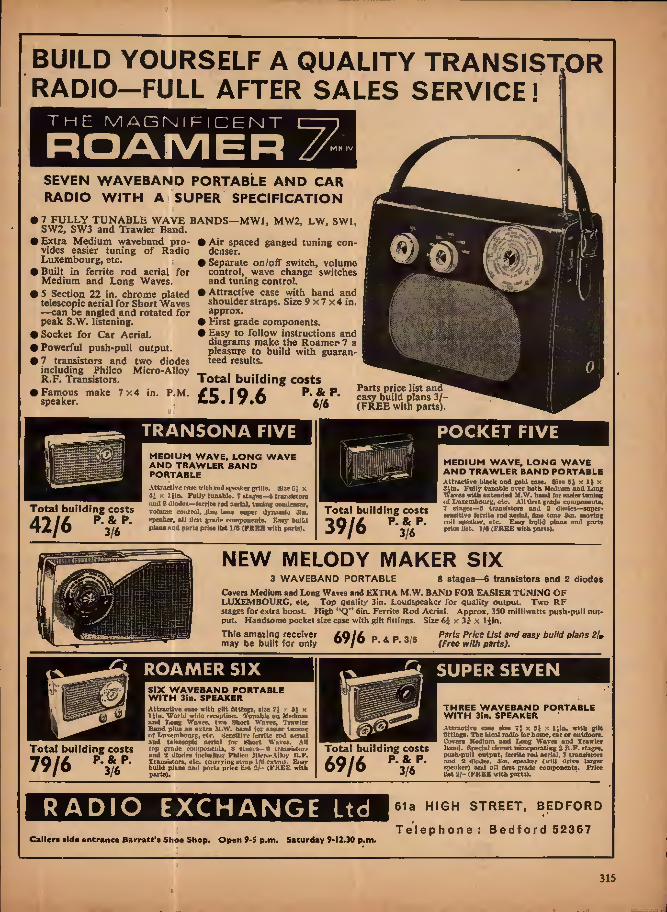
BUILD YOURSELF A QUALITY TRANSISTOR
RADIO—FULL AFTER SALES SERVICE!
the magnifi CEI NT
ROAMER /XMH IV
SEVEN WAVEBAND PORTABLE AND CAR RADIO WITH A SUPER SPECIFICATION
7 FULLY TUNABLE WAVE BANDS—MW1, MW2, LW, SW1, SW2, SW3 and Trawler Band.
• Extra Medium waveband pro- vides easier tuning of Radio Luxembourg, etc.
• Built in ferrite rod aerial for Medium and Long Waves.
• 5 Section 22 in. chrome plated telescopic aerial for Short Waves —can be angled and rotated for peak S.W. listening.
• Socket for Car Aerial. • Powerful push-pull output. • 7 transistors and two diodes
including Philco Micro-Alloy R.F. Transistors.
• Famous make 7x4 in. P.M. speaker.
i Air spaced ganged tuning con- denser,
> Separate on/off switch, volume control, wave change switches and tuning control.
i Attractive case with hand and shoulder straps. Size 9x7 x4 in. approx.
i First grade components. > Easy to follow instructions and diagrams make the Roamer- 7 a pleasure to build with guaran- teed results.
Total building costs
£5.19.6 p^p
>■- fiY. *
m
Parts price list and easy build plans 3/ (FREE with parts)
Total building costs
42/6 P-3V
TRANSONA FIVE
MEDIUM WAVE, LONG WAVE AND TRAWLER BAND PORTABLE Attractive caso with rcJ speaker grills. Sizefi, x 4! x 3 tin. Fully (unable. 7 sUges—a trnjisistora nuil 2 Ulottes—(errite rod aerial, tuning coaUeuser, rolmne control, 41 ne tone super Jynamlc gin. epeater, all ilrst grade components. Easy build plans aad parts price list l/fl (FREE aith pwlsl.
POCKET FIVE
Total building costs
39/6
MEDIUM WAVE, LONG WAVE AND TRAWLER BAND PORTABLE Attractive black and gold case. Size x IJ X 3ilii. Fully tunable over both Medium and Long Waves with extended M.W. band (or eoaiertoning ol Luxembourg, etc. All Brat grade components, 7 stages—6 transistors and 2 diodes—super- eensitive ferrite rod aerial, fine tone Sin. moving coil speaker, etc. Easy bolld plans and parts price list. 3/9 [FREE with parts).
NEW MELODY MAKER SIX 3 WAVEBAND PORTABLE 8 stages—6 transistors and 2 diodes
Covers Medium and Long Waves and EXTRA M.W. BAND FOR EASIER TUNING OF LUXEMBOURG, efe. Top quality 3in. Loudspeaker for quality output. Two RF stages for extra boost. High "Q" 6in. Ferrite Rod Aerial. Approx, 350 milliwatts push-pull out- put. Handsome pocket size case with gilt fitiirrgs. Size 6i x 3J x liin.
Paris Price List and easy build plans (Free with parts).
This amazing receiver AO/A p . p may be built for only "'/O p- ^ P- 3/6
ROAMER SIX
Total building costs
79/6 PAP-
SIX WAVEBAND PORTABLE WITH Sin. SPEAKER Attractive case with gilt fittings, size "i >. 31 x IJln. World wide reception. (Tunable on Medium and Long Waves, two Short Waves, Trawler Band plus an extra M.W- band for easier toning ot Luxembourg, etc. Sensitive ferrite rod oenal and telescopic aerial for Short Waves. AH top grade coiupoueiiis, 8 stages—0 (nuwiaturs and 2 diodes including Fhiko Micro-Alloy It.F, Transistors, etc. (carrying strap 1(9 extra), Easj- build plans and parts price list 2/- (FKEE with parts).
^ SUPER SEVEN
Total building costs
69/6 p-y-
THREE WAVEBAND PORTABLE WITH 3in. SPEAKER Attractive ca*e size 75 x 5S r< lila. with gilt flttinffi. The idea* radio for home, car or ouWoore, Covers Medium and Locj Wftvce and Trawler Band. Special circuit incorporating 2 B.F. et-ageg, puBh-pulJ output, ferrite rod aerial, 7 transfstora .-iml 2 dfodca. 3m. speaker (will drive larger speaker) and all first prade componentH. Price list 2/- (FKEE with parts).
RADIO EXCHANGE Ltd
Caller* side entrance Barratt'j Shoe Shop, Open 9-5 p.m. Saturday 9-12.30 p.m.
61a HIGH STREET, BEDFORD
Telephone: Bedford 52367
315

SS»r«lS!!e A
(MINUS X)
ALPHABETICALLY...
we can list the names
GEOGRAPHICALLY...
we can list the countries
All over the world students know that CREI HOME STUDY COURSES are sup- plying the answer to their need for advanced Technical Education in the field of Electronic Engineering Technology.
CREI PROGRAMMES ARE AVAILABLE IN; Electronic Engineering Technology Industrial Electronics for Automation Computer Systems Technology Nuclear Engineering Mathematics for Electronic Engineers Television Engineering Radar & Servo Engineering Citv & Guilds of London Institute: Subject 49 and Advanced Studies Subject No. 300
Write for free brochures to: C.R.E.I. (London) (Dept. P.E.8 )
WALPOLE HOUSE,173/176SLOANEST.,LONDON S.W.I Telephone: Belgravia 8662
INTERNATIONAL DIVISION OF CAPITOL RADIO ENSIH6ERINE INSTITUTE WASHINGTON O.C. l-^ —^ —— 1 "I
Please send me (for my information and eniireiy without obligation) full details of the educational programmes offered by your institute. | | Send details of the City 8 Guitds Programme Q
Name Address
Electronics Experience
T«Ax»<.r^'aBS -vai vt- WE HAVE A COUP LETS EAH&E Or HEW A8D OLD TTVES OF VALVSS. TUAJraiS- TOBS AJTD DIODES. FULL LISTS AVAIL- ABLE OH APBUCATIOK.
OC3 Bh OC16 »/-- OC23 16/- OC38 12/8 OC22 10/- OC24 17/8 OC25 8/8 OC29 16/- OC35 12/8 0036 12/8 OC1I Bh OC42 61- OC44 6/- OG46 2/8 OC68 18/6 OC70 4/- OCTl *h OC72 6/- OG73 8/8 OC75 8/- OG7S 61- 0077 71- OC78 Bh OC78D 61- 0C81 6h 0C81D 6/- OC82 «/- OC123 11/8 0CIS9 8/- OC14010/- OC170 8/- ocm 71— 00200 7/8 0020112/8 00202 18/8 OC20S 10/8 OC204 15/- OC205 1S/- 0020619/8 001*7118/8 8172115/- ST723 10/- 3T140 4/- ST141 8/- V62R 6/- V64H, «/« V68R 71- V10SOA 0/- V1520P 10/- V1530P10/- V130S0P 8/-
V6020IT 8/- V9030 10/- BFY60 8/8 Spy 6i 71- FV62 6/- BYZ12 10/- BYZ13 10/- Bcvas 7/8 BCY34 8/8 BCY10 7/6 BGY38 9/6 BGY39 12/6 BCY12 7/6 AC107 14/6 AC127 ACY1T ACY10 ACY20 A0YB1 ACY22 AP102 18/- AF114 71- ABllB AF110 AF117
8/- 8/6 8/6 5/6 «/- 4/6
AF118 17/6 AF124 10/- AB126 10/- AFJ2S 10/- AF127 9/6 AF130 101- AF186 17/8 AFZ11 17/- AFZ12 12/8 A8V2fl 6/8 MAT 100 7/9 MATlOl 8/8 MAT120 7/9 MAT121 8/8
HOTOA BAHC.AINS
Made by CroQipton Parkineon. Siogle jiluw i h.p. Motor. 230/260V: 60 cycles, 1-3A, 1,426 r.p.m. Coatlnuoua ratio(?. Hplmllc l|in. :< Jin. dia. Overall elzc less apindlc approx. 8 x Olo. Perfect coodilloo. A bargain lot Ibc workbench. OSLY 78/8, Cairiage 26/- (i h.p. Motor atao available 99/8, COTiagc 20/-1.
BL84 9/8 EF86 9/8 BY86 8/6 DY87 9/8 KCC83 8/6 J5CC81 5/8 BABC80 8/8 UL84 8/8 tJF41 10/8 Uy4I 8/8 P.P. and Insurance 2/-
Ideal for model tnakera, record players, tjpe decks, etc,' 6.8 d.c. Motor- 10,900 r.pan. at ZSOmA. IJln X Xln dia. Shalt iin long X S/64ln dia. 9/6. P. & P. 2/6. 9V d.c. Brim deck replacemant motor. 21n X IJln dia, Shalt Jin long x 3/32m. 17/8, P. & P. 2/-.
i H.P. MAINS MOTOR
SELECTOR DRIVE Sumeroua applica- ttona. Electro magnet and braen tooth wheel.' A ewltch wafer and oontocta are . mi —- coupled * to thla
ami arranged to be on for 19 pulses and off for 16. An Anxlljary contact is normally on but oB 1 in every £8. Complete with suppressor, resistors, plus scries contact lor continuous operation. Ideal window displays, switching lamps, models, etc. 12V or 24V d.c. Brand new and boxed 12/8. P. ft P. 2/0.
SYNCHRONOUS CLOCK MOTORS Geared lor 40 revolutions per hour. 230V 69 cycle. With a aantlag flanges. Sirs approx. Ilia, deep x 2llii. dia. ONLY 28/6. P. ft P. 2/6.
DELAY ACTION TIME SWITCH
Made by Smiths. A.C. operation 200/ . 250V. Double pole, will give time delays from 9-10 minutes. Size 2iin. din. X 2fin. long ino. ■Jin. x 3/l6ln dia. spindle. EARQAIN PRICE 17/8. P. ft P. 2/6.
UNREPEATABLE BARGAINS '
FANE 122/17 121n 25 WATT HEAVY DUTY HI - FX LOUD SPEAK- ERS With high eflloionoy Anti- stroplo Ferrite inognet. 17,000 gaues. Imp. 3-6 ohms. Brand new and guaranteed. List Prica 212.' MKD AIR PRICE £8.19.8. P. ft P. 7/6.
B.MX COMBWATIOR LOUD SPEAKERS 13i x 8Jin. Elliptical with ajln dia. Tweeter. Imp. 8 ohms. Power handling 10 watte. Brand new and guaranteed. List price 28.6.0. USD AXR PRICE 99/6. P. ft P. 7/8. (Also available without tweeter 69/6 P. ft P. 7/6). Fane 302 3in TWEETERS, imp. 3-5 ohms. 17,090 gauss. 12 watt. Brand New and guaranteed. List Price 23.15.0. LIND-AIR PRICE 69/9. P. ft P- 3/6.
0
^C.R.E.I. (LONDON) (DEPT. P.E.8), WALPOU HOUSE. i73-f?5 SLMNE STREET. S.W.I^ ff££ LIND-AIR OPPOSITE

LIIMD-AIR 1 ■ ■ ■ 1
(OPTROMICS) LTD. i Shop3 A
Tel. 01-580 453417679 Open 9-6 p.m. Monday to Saturday inclusive. Open Thursday until 7 p.m.
ALL POST ORDERS TO Dept. P.E. 568 25 Tottenham Court Road London, W.I
l-J WATT AMPLIFIER An Ideal baals for bniltUng your own port- able record player. Jtut add speaker and turntable, and yon will have an above- average model lor a mere fraction ot the coet. 2-3 watt' printed circuit with control panel on flying lead. ON/OFF, TONS CONTROX. AND VOLUME, colonrful eMotobeoo. Brimar vahea: BZ80, KCL82 and compoelte Installation booklet. Price £4 g Q P. A P. 3/8.
MAGNAVOX-COLLAtlO Ml TAPE DECKS The very lateat S-speed model—I}. 3|, i.pj. available with either 3 track or 4 track head. Features Include: Paose control; digital counter; faat forward and rewind; new 4-pole, fully screened Induction motor; interlocking keys. Sire of top plate J8J x 11 x ejln deep below unit plate. For 280/250V a.c. mains, 00 c/s operation. New, unused and fully guaranteed. ^ £10.10.0 £13.19.6 Carriage and Packing 12/8 extra.
MAKTIN TAPI AMI'l'StftS FOE USE WITH ABOVE BECKS 2 track model £14,18 8; 4 track model £16.19.8. Carriage and Packing 12/8.
ROMTWfTTf
TFS
HULTIME T t*5 9 in I ELECTRONIC KIT MODEL TTC.lOOl. 20.000 O.P.V. with overload pretecthm; d.c. volts, 8,23,126, BOO, 2,600V: a.c. volte, 10, BO. 260. 100 V; d.C. mA 260mA to 50A. With prods and Carrying ease ONLY 88/-. P. A P. 3/8.
MODEL XTC. 1030. 50,000 OJ.V,; d.C. volts, 0-3, 12, 60, 120, 300, 600. 1,200V; aid. volte, 8,80. 120, 600, 1,200V; d.C. mA 6-03-300. With prods nod carrying case ONLY 811.19.6. P. & P. 6/-.
©
AUTO TRANJSOSWtHS
Input 0-200,220. 240V Output 110V BOW £1.7.6 76W £1.17.0 100W 88.6.0 1B0W 88.16,0 200W 88.6.0 300W 84.6.0 400W 84,10.8 600W 86.9.8 600W £0.6.8 Post extra.
l.QOOW 89.9.0 1.6O0W 816.16.0 S.OOOW 818.10.0 3.000W 828.10.0 4,000W 884.18.0 0-80V. 1A 80/- 0-80V, JA17/0 0-S0V. 2A 17/6 0-30V, 8A 42,'-
Bulld nine different prelects from one baste kit—simple Instructions, no tech- nical knowledge required for you to build a Police Siren, Metronome, Morse Code anrpllfler. Electroolo Massager, W/T Transmitter. Badkt. Telephone, One- tramdsior Eadio Two-transistor Radio, Electronic Music Kit. Completely safe- operated oq 9V PP3 battery. Hours of bin for boys and dads of ail ages. Complete with all parts and simple step by step hvrtrnotlons. ONLY 80/8, P. A P. 5/.. AERIALS TV UHS VHf STEREO
Vantena Table Top' V Aerial BBC/1TV, 88/8. Creita Boom Aerial Bond I/JI/1II. Cream or Black. 88/6. Yesmuter Table Top VHF/TJHF Tunable Aerial. Chrome or Grey, 78/6, YAOl all Channel Table Top Aerial BBC1/ 2/ITV1VHF, 86/-. HL628 Loft Aerial HJXO V + B for vertical Band I/JII. With mounting arm and bracket, 68/-. New Hsjor 10 element BBC2 Aerial for lott or outdoor axing. With rotter bracket for op to 2ln dla. mast. 45/9. HI. Hunter IS element BBC2 Aerial as above, 57/-. Kl, Explorer 18 element BBC2 Aerial as above. 69/-. Lolt Six. 6 element BBC2 Aerial lor loll or outdoor fixing. With arm and brocket. 87/8. T-Beam 4 clement outdoor Baud II VHF/FM Stereo Aerial. With mast, 87/-. Please add 4/- postage.
mains TRANSfORMERS H STFREO HEADPHONES Input 200-2S0V BOc/s. 24V 3A £2.12.8 24V 8A *8.6.0 24V OA 98.16.0 24V 12A 88.16,0 Post extra. Mains and Output Tnuuformer Hate avail- able on request. aOODMAKS SPEAKER BAKQAIKSI Sin 3 ohms, 16/6; flln. 3 ohm, 29/6; Sin, 3 ohm, 82/fl: llln 6 ohm. 88/-: 10 x 61n. 3 ohm. 88/8; Tweeter. J0/8. P. & P, 3/6 per Speaker.
see opposite
8TKR.RO HEADPHOffSfl Enjoy Stereo Sound as you have never heard It before. MODEL TTC. Qllll as Illustrated - soft padded ear- phones. Adjustable headband. Impe- dance 8 ohms per phone. Frequency range aS-lS.OOOc/s. With Sit lead. Price 89/8. P. * P. 4/6. Other similar types available. AKAI ASEfiS. 8 ohms, 88.8.0; CORAL EI02, 18 ohms, 85.19.8; EAGLE 8E1, 16 ohms, 79/6. T.T.C. Btetboseope, 8 ohm*. 49/6. P. fi P. 4/6 each.
6*.
TEAK FINISH PLINTHS with perepex cover 6i gns. (for LAB80 8t gns.). P. A P. 12/6 Agents lor Tboreos, Dual. Ooldrlng, etc.
6ARRARO DECKS 3000 with Boaolone 9TAHC Stereo Cartridge .. 18.19.6 3000 with Souotoue 9TABC Diamond Stereo Cartridge .. 89.U,6 AT80 MK1 less cartridge .. 810.19.8 ATSO MKH less cartridge .. .. *12.19.8 ATM MKII with Decca Derain Stereo Cartridge 817.14.0 SP. 25 MKII less cartridge £10.19.8 SP. 25 MKII with Decca Deram Stereo Cartridge 816.14.0 AP.75 less cartridge *23.11.8 LAB.SOMKII less cartridge .. .. 824.19.8 All plus P. * P. 12/6 Mono Cartridge 17/6 extra. Stereo Cartridge 22/6 extra.
TRANSISTOR F.M. TUNER
SAVE £2.2.0 6 Ttansleior FM tuner. Frequency range 88- 108Mo/s. Sire 6 x 4 x 2}in. Beady built for use with most amplifiers, 9V battery operation. Completelwith Instructions. LIST PEXCB 9 gne, LIND AIR PRICE 7 gns. P. A P. 4/-.
Multiplex adaptor lor Stereo Radio Reception 86.19.8 extra.
Specially ileslgned to replay the well known and popular Mnelcasaeltes—prerecorded tape cassette offering a wide choice of all types of music from pop to classical. Up to 40 minutes of quality repre- ductkm through built-lo speaker. Simple off/play and volume controls. Fully transistorised operating on six penllght batteries. Modem compact atyllng with earpiece socket and wrist strap. Sire 6i x 4i x 2iQ. LIND AIR PRICE, £9.19.6. &***' ^
COMPLETE HI-FI STEREO SYSTEM ALL TRANSISTOR 6 ONLY WATTS PEE CHANNEL STEREO El-FX SYSTEM OFFERING A PEBFOH- MANCB EQUAL TO IP NOT BETTER THAN SIMILAR SYSTEMS COSTING UP TO DOUBLE THE PRICE.
•Modern styling plus ad- vanced elroultry using latest silicon transisiora tbroofhont. . vr _ The fwnorw GARBARD 3000 Record Ciumger fitted lifchtweight lubular ann with SONO- TONE 9TAHC STEREO/MONO DIAMOND CARTRIDGE will piny oil sires of records. (4 speed! 78, 45, S3 1/3,16 2/3 r.p.m.). Will play up to 9 records automatically, also pro- vision for manual play. Ampllfiera and controls are mounted below record player and Incor- porate Boss. Treble. Volume and Balance controls oad On/Off. Cram/Radio, Mono/Stereo slide switches. TWO IDENTICAL LOUDSPEAKER SYSTEMS each Incorporating separate base speakers and high frequency units with crossover network provide full frequency reproduction and are complete with 10ft leads and plugs for connection to amplifier. Will fit easily on to bookahelves. room dividers or existing furniture. BRIEF SPEC. PJayer/Ampllfler unit, Teak finish, size I6i X 14 x Slln U0O/26OV a.c. operatioo. Inputs lor Radio Tuner/Tape Recorder also ontpute lor Tape Recorder. Loudspeaker Systems. Teak finish, site teach) IS x 7 x 81n. Supplied complete with Instruction booklet, ready to plug In and play. SEND YOUR ORDER NOW OR CALL AND HEAR THIS MARVELLOUS HI-FI STEREO SYSTEM (Teak flnlsb). Only 69 fU». plus 29/- Carriage and Insurance, (Rosewood 8 gns. extra.) (Clear Pcrspex Cover 3 gns. extra,)
3S GNS.
ra
LINEAR AMPMfiCRS |
p
s Latest a.c. Mains Models oflerfa* highest quality | at modest cost. „ , , ! r.t8«. AH Transistor 12 watte Stereo. Inpute for f -runer. Gram, Mike. Separate Bass, Treble, || Balance and Volume Controls 816,16,0. Carr# 7/8. Teak case 89.10.0 extra. PTA 16 (as I tins.). All Translator, 10 watte Mono. Inputs for Tuner. Gram, Mike. Gulter, Bass. Treble and two volume controls, £16.16.0. Carr. 7/6. Teak case 88.10.9 extra. LT46, 2 Valve G watte Mono. Inputs for Tuner, Gram, Baas, Treble and volume controls, 88.19.8. Carr. 7/6. Metal cover IB/-extra. Full details sent on requret.
317

Jjt&o&l
20 WATT
SOLDERING
INSTRUMENT
# CONTROLLED TEMPERATURE
Design holds max. temp, of 380oC. within close limits.
# EASY BIT REPLACEMENT
Simple, fast replacement of low-cost copper bits. Non-wearing PERM ATIP bits cut servicing costs.
# BEAUTIFULLY COMPACT
Length 7|'. Weight U oz. Max. handle dia. 0.715'
# UNEQUALLED PERFORMANCE
Ideal for fast production soldering on the majority of modern electronic equipment.
0 ALL VOLTAGES
The LITESOLD range includes six other models (10,18. 25, 30. 35 and 55 watts), and many accessories. Please ask for colour catalogue L'37.
LIGHT SOLDERING
DEVELOPMENTS LTD.
28 Sydenham Road, Croydon, CR9 2LL Tel. 01-688 8589 & 4559
318
FANTASTIC BARGAINS
SONOTONE
SOLENT
2 SPEAKER
HI-FI
SYSTEMS # LIST £18 EACH
SPECIAL
OFFER
17 gns.
# Impedance 8 ohm. Power input up to 12 watts. 0 Suitable for valve or transistor amplifiers. # Frequency response 40c/s to 20 k/cs. # Scandinavian style cabinet, # Small attractive size 14 x 9 x 84. 9 On permanent demonstration. 9 Reviewed by Hi-Fi News, The Gramophone, etc. Send large s.a.e. for FREE Leaflets and Test Reports available
from our Showrooms.
EACH POST 9/-
J. J. FRANCIS LTD. 123 ALEXANDRA ROAD
London, n.s bow 1662
LEE ELECTRONICS 400 EDGWARE ROAD
RADDINCTON 5521
BUILD YOUR CIRCUITS
on
VEROBOARD —the Universal Wiring Board—' obtainable from your local Retailer Trade enquiries lo; NORMAN ROSE (ELECTRICAL) LTD. 8 St. Chad's Place, Gray's Inn Road, London, W.C.I Technical enquiries to: VERO ELECTRONICS LTD. industrial Estate, Chandler's Ford, Hants
All item* proviouily ad- vertised available, alto tee item* advertised In Prac- tical Wirele**. Huge Hi- Fi and Components stock* at all branches.
TECHNICAL
'fRADING
* LONDON (MUS2639) 10 Tottenham Court Road PORTSMOUTH tTV. 22031) 350-151 Fratton Road
* SOUTHAMPTON (Tel. 2i«Si) 72 East Street * BRIGHTON (Te). 23975) 6 Oueen's Road
alt moil order Brighton
FANTASTICALLY POPULAR TAPE
We otter roa lallr ttntllmi polreiter/mrlu and P.V. 0, tapes ol Identical qnality hl-fl, wide range tecordln* ebaracteristica as top grade tapes. Quallip control manolactnre. The* are tmJ: worth a tew more coppers than acetate, sab-standard, Jointed or cheap imports xar orb Aim prove it xotoseu. Standard Pta* Sin. IKtlt. E/t 4in. 30«ft. 4/8 Shi. 600ft. 7/8 Sjia. »00<t. 10/8 71b. 1.200ft. 18/8 Doable Pta* Sin. 300(1. 4in. 600(1. Sin. 1.200tt. Sjln. 1,800ft. 7in. 2.400It.
4h 61- 15,'- 10/8 87/-
3m. tel. Sin.
Dong Pit* 225ft. 450ft. 900ft. Sltn. 1.200ft. 7in. 1.800ft. Triple Pla* 4In. 900ft. 5>n. 1,800ft. Siin,2,400ft- 7in. 3,600ft. Qasdrnpie Pit* Sin. 600ft. 8/8
8/8 6/8 10/9 18/- 18/9 18/- SSh 34/- 44/-
Potlagtt 1/- reel. Past Pree less 6% on three reels. Dnantit* and Trade emoiries inrited. ROTE, iarpo fepe tlocit al alt iranrhct.

"'-n >>,0 g:
-:W:
'.^zo- T^& —— r?
PRINTED CIRCUITS
Five aaworled piloted circuit boards with trwnittora, diodes, resUtets, conden- sers. etc. Guaran- teed mlnlmam 20 Inmsistcre. Ideal lor experi- meotera. 6 boards lot V)l— P. * P. E/-.
P.M. WIRELESS MICROPHONES 84-I0<Mc/b. Tranaistor- taed. Operates Irotn 9V battery. Complete with additional seerel tie-clip (nicrophooe.Liat £12.10.0 ONLY M/15/0. P. ft P. 2/6. These cannot be operated in U.K.
MODEL TE.SO 20,000 O.P.V. MDITIMETER
0/10/80/100/#00/ 3.000V »,o. 0/8/26/ 80/280/ 600/ l,000v. d.c. 0-60uA 6/60/ 600mA. C/O/SOK/ 600K/6i»l.«/X7/6, P. ft P, 31:
NEW MODEL M0 30,000 o.p.v. 'With overload protection, mirror scale 0-6/1/2-6/ 10/28 /100 / 250 /600 / 1,000 V d.c. 0/2-6 / 10 / 25/100/250/ 600/1,000V a.c. O/S0aA / 5/ 60 / 500mA 12A d.e. o/eokn/fiMa/eoMQ- £8/17/0. Post Paid. MODEL ZQU TRABSISTOft CHECKER It has the fullest capacity for checking on A, B and Ico. Equally adaptable for checking diodes, etc. Spec.; A; 0-7-O 9B67. B: 6-200. Ico: 0-60 mtcroampa 0-8raA. Resistance (or diode ZOOO-IMO. Supplied complete with Instructions, battery and leodi. C5.19.6. P. ft P.2/8.
VARIABLE VOLTAGE TRANSFORMERS
Brand New—lully Shrouded. Input 230V 60/60c/e. Output 0-280V. 1A .... JW.IO.O 2-6A *8.16.0 6A *9.16.0 8A *14.10.0 10A *18.10.0 12A *21.0.0 20A ........ *87.0.0 Post extra.
SILICON RECTIFIERS aoov P.I.V. 200mA 2/0 200V P.l.V. 8A 6/8 400V P.I.V. 3A 7/6 l.OOOV P.I.V. 6A 7/8 400V P.I.V, OA 6/8 400V P.I.V. 8A 7/8 l.OOOV P.I.V. 680mA 8/8 800V P.I.V. 600mA 6/8 800V P.I.V. 6A 7/8 400V P.I.V. 600TOA 8/8 70 V P.I, V, 1A 2/8 160V P.I.V. 186mA 1/- IllflV P.I.V. 25A 10/8 700V P.I.V. 100A 40/8 400V P.I.V. 3A (3.C.R.) 7/8 100V P.I.V. 6A (S.C.R.) XS/6 200V P.I.V. BA (8.C.R.) 16/0 400V P.I.V. 6A (8-C-R.) 17/8 DitcounU lor quantities. Post extra.
sir TRAWBISTORISED FX TDBKE 6 TRANSISTOR HIGH QUA- LITY TUNES. SIZE ONLY 6In x din x 2Jln. 3 LF. stages. Double tuned dlsorlminator. Ample output to feed most amplifiers. Operates on SV battery. Coverage 8S-108Mc/b. Ready built ready for use. Fantastic valac for money. SOW *8/7/8. P. ft P. 2/6.
STEREO MULTIPLEX ADAPTORS S gns.
AVOMETERS Supplied in ex- cellent condition fully tested and checked. Com- plete with prods, leads and Inatruo- thins. Model 47A 19.18.8 Model 8 *18.
Model 9 *20. P. A P. 7/6 each,
TE22 SINE SQUARE WAVE AUDIO GENERATORS
Sine: 20«/a to 200 ko/a on 4 bands. Square: 20c/8 to SOkc.'B, Output Imped- ance 6,000 Ohms, 200/260V a.c. Supplied brand new and guaran- teed with Inatroc- tion manual and leads, *16. Carr, 7/9. TE-20RF SIGNAL GENERATOR
Accurate wide range signal gen- erator covering 120kc/8 — 260 Mo/s on 9 bands. Directly cali- brated. Variable R.P. attenuator. Operation 200/ 240V a.c. Brand new with lostructioDS- *12/10/0. P. ft P. 7/6. S.A.E. for details. LAFAYETTE TE-46 RESISTANCE
CAPACITY ANALYSER 2pf - 2,000 mfd 2 ohms 200 megohms. Also checks Im- pedance turns ratio, InHuIation. 800/260V a.c. Brand Hew *15. Carr. 7/8.
ARF-100 COMBINED AF-RF SIGNAL GENERATOR
AP. 8 [HE WAVE 20-200.000 c/s. Square wave 20- 30,000 c/s. O/P, HIGH IMP. 31V P/P 600 [J S-8V p/p. TF. 100kc/o-800 Me/a. Variable R.F. attenuation int/exl. modu- lation. Incorporates dual purpose meter to monitor AF. ootpnt and % mod. on H.F. 220/240V a.c. *27/10/0. Carr. 7/9. TE-G5 VALVE VOLTMETER
High quality taatru- ment with 29 ranges. D.e. volts I-fr-l^OOV A.c. volts 1-6-1,500V Resistance up to 1,000 MO- 220/240V a.e. opera- tion. Complete with probe and instructions. *16. P. ft P. 6I-. Additional rroWes. available: R.F. 36/- H.V. 42/8.
*
6
Catalogs® j
\ Iqulp"1®1"
CATALOGUE
★ ELECTRONIC COMPONENTS ic TEST EQUIPMENT ic COMMUNICATIONS
EQUIPMENT if HI-FI EQUIPMENT
We Me proud to introduce out Brit comprehensive catalogpe o! Electronic
Components and Equipmeol. Over ISO page* lolly IDnstrated, fitting thomand* of Hem*, many at bargain pricet. Free diacount coupons with every eatslogne. Everyone hi electronic* ibonld have a copy.
CLEAR PLASTIC PANEL METERS First grade quality Moving Coll panel meters available ex-stock. B-A-E. for illustrated leaflet. Discount for quantity. Available ns follows: Type MR 38P, 1 21/32In square fronts. 100-0-100(^82/8 6O0-O-6OfluA 86/- l-O-l mi 26/-
80uA 87/B lOOuA 36/- 200(iA 82/8 600uA 27/9 I-6-BOij
IroA., 26/- 2mA.. 26- omA.. lOdlA £6/- 20mA 26/- BOmA 26/-
60 0(( A.... 86/- 100mA 26/- ISOmA.... 86/-
200mA .. 300mA .. aOOmA .. S60m.i ., IA d.c. .. 2A d.c. .. 3A d.c.., 3V d.c... 10 V d.c. 20V d.c
28/- . 25/- , 26/- ,26/- . 26/- . 25/- .28/- .26/- 25/- 25/- 80V d.c,. 26/-
IQOVd.c. . 160V d.c. . 300V d.c, . 800V d,c. . 760V d.c, . 16V a.c. , 60V a.o. . 150V a.c. 300V a.c. 600V a.c. , •S' Meter . POST EXTRA. Larger sizes available—send for lists.
26/- 26/- 25/- 26/- 28/- . 26/- 28/- . 28/- . 26/- 85/- 1mA 28/6 ADMIRALTY B.40 RECEIVERS
Just released by the Ministry. High quality 10 valve receiver, manufactured by Mnrphy. Coverage In 6 bands OSOkc/s-SOMc/s. I F. BOOkc/s. Incorporates 2 R.F. and 3 X.P. stages, bandpass filter, noise llmiter, crystal controlled B-F.O., calibrator, I.F. output, etc. Balit-in epcaher, output for phones. (Operation 160/230V e.c. Size 19|to X 13}la x 16ln. Weight 114 lb. Offered In good working condition, *22.10.0. Cart. 30/-. With circuit diagrams. Also available B.41 LA', version of above, 16kc/B-700kc/a. *17.10.0, carr. 30/-. UNR-30. ^-BAND
COMMUNICATION RECEIVER
Covering 650 Kc/s — 30 Mc/a Incorporates variable BFO for CW/S8B reception. Built- in speaker and phone Jack. Metal cabinet. Operation 220/24OV. A.C. Supplied brand new, guaranteed with InatruetlODS. £12.10.0 Carr. 7/6 HEW LAPATETTE MODEL HA-700 AM/CW/ 8SB AMATEUR COMMDHIOATIOK RECEIVER 8 Valves, 6 bands Ineorporatlng 2 MECHANI- CAL FILTERS for exceptional selectivity and sensitivity, Frequency coverage on 6 bands 160-400 ko/s 660-1,8fl0kc/fl. l-6-4-0Mc/s, 4-8-14-6MC/5 10'6-30Mc/a. Cixcult incorpor- ates R.P. stage, aerial trimmer, noise Ifmller. B.F.O. product detector, electrical bandspread, H meter, slide rule dial. Output for phones, low- to 2k 0 or speaker 4 or 8(J, Operation 220/240V a.c. Size TJin x ISln x lOin. Supplied brand new and guaranteed with hand- book 89 GHS. Carr. 10/-. S.A.E. for leaflet.
R.C.A. ARBS SPEAKERS Sin, 3 ohm epeakers In metal case. Black qrackle flnlBh to match oar 88 Receivers. AVHllablc Brand New and Boxed with leads, 59/9. Carr. 7/C. UMTETTE LA-224T TRANSISTOR STEREO AMPLIFIER
19 transistors, 8 diodes, 1HF musio power, 30W at 8n. Response 30-20,000 ± 2dB at 1W. Distortion 1% or less. Inputs 3MV and 260JIV. Output 3-16(1. Separate L. and R. volume controls, Treble and boss control. Stereo phone lack. 'Brushed aluminium, gold snodlsed extruded front panel with compli- mentary metal case. Site lOtin x 3A-x7ftln. Operation 116/230V a.c. *26. Carr. 7/9. SINCLAIR EQUIPMENT
Z.12 12 watt ampufler, 89/8. FZ4 Power Supply Unit, 89/6. Stereo 25 Preamp., 19,19,8. Q14 Speakers, *8.19.9. Mkromatk Radio Kit, 49/6. Built, SO/e. Micro FT Badio Kit, *6.19.9. ALL POST PAID
SPECIAL OFFER 2 Z12 Amps.. FZ4 Power Supply. Stereo 26 Pre- amplifier, *22,
»j ■'r/M'S'X '
I 13 (RADIO) LIMITED P/ionc CERRARD 8204/9155 Cables: SMITHEX LESQUARE
3-34 LISLE STREET, LONDON, W.C.2
319
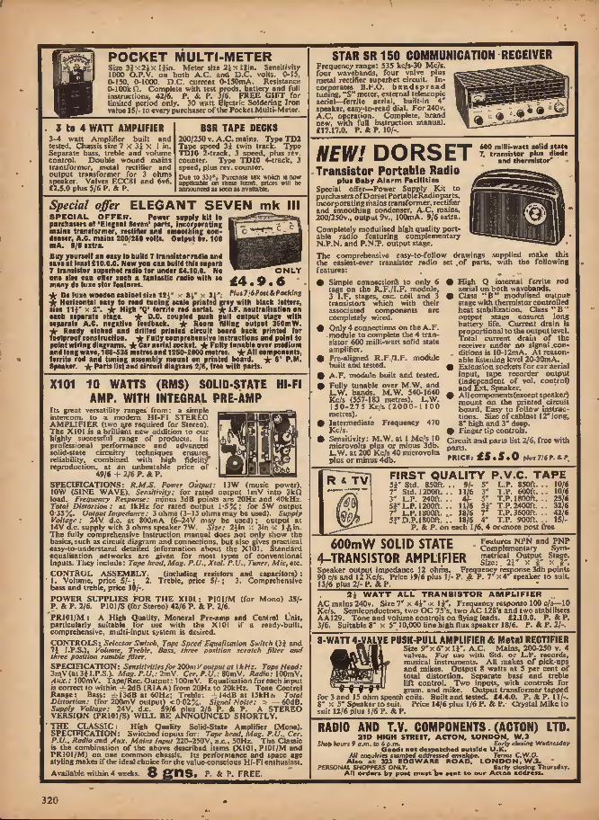
POCKET MULTI-METER Size 3| x2i >i I Jin. Meter size 2} x I (in. Sensitivity 1000 O.P.V. on both A.C. and D.C. volts. 0-15, 0-150, 0-1000. D.C. current O-ISOmA. Resistance O-l00k Q. Complete with test prods, battery and full instructions, 42/6, P. & P. 3/6. FREE GIFT for limited period only. 30 watt Elfctric Soldering Iron value 15/- to every purchaser of the Pocket Multi-Meter.
3 to 4 WATT AMPLIFIER 3-4 watt Amplifier built and tested. Chassis size 7 x 3i x I in. Separate bass, treble and volume control. Double wound mains transformer, metal rectifier and output transformer for 3 ohms speaker. Valves ECC8I and 6v6. £2.5.0 plus 5/6 P. & P.
BSR TAPE DECKS 200/250 v, A ,C. mains. Type TD2 Tape speed 3i twin track. Type TDI0 2-track. 3 speed, plus rev. counter. Type TDIO 4-track, 3 speed, plus rev. counter. Due to 3ii% Purchase tax whicn is now applicable on these Items, prices will be announced as soon as available.
Special offer ELEGANT SEVEN mk III SPECIAL OFFER. Power supply kit to purchasers ol 'Elegani Seven' parts, incorporating mains transformer, rectifier anil smoothing con- denser, A.C. mains 200/250 volts. Output Sv. 100 mA. 9/6 extra. Buy yourself an easy to build 7 transistor radio and save at least £10.0.0. Now you can build this superb 7 transistor supsrhet radio for under £4.10.0. No one else can offer such a fantastic radio with so many do luxe star features. •k De luxe wooden cabinet size I2i' x BJ' x 3i':
ONLY £4.9.6 Plus 7/6 Post & Packing
-*■ Horizontal easy to read tuning scale printed grey with black letters, size Hi' x 2*. ★ High 'fj* fernte rod aerial, l.F. neutralisation on each separate stage. * D.C. coupled push pull output stage with separate A.C. negative feedback, -fc Room filling output 3S0mW. ic Ready etched and drilled printed circuit board back printed for foolproof construction. * Fully comprehensive instructions and point to point wiring diagrams, yt Car aerial socket. ■ArFully tunable over medium and long wave, 168-535 metres and 1250-2000 metres. •A* All com ponent9; ferritc rod and tuning assembly mount on printed board, -k B' P.M. Speaker. Paris list and circuit diagram 2/6, free with parts.
X101 10 WATTS (RMS) SOLID-STATE HI-FI AMP. WITH IHTEGRAL PRE-AMP
Its great versatility ranges" from: a simple intercom, to a modern Hf-FJ STEREO AMPLIFIER (two %re required for Stereo). The X10I Is a brilliant new addition to our highly successful range of products. I is professional performance and advanced solid-state circuitry techniques ensures reliability, combined with high fidelity' reproduction, at an unbeatable price of
49/6 + 2/6 P. & P. SPECIFICATIONS: R.M.S. Power Output: 13W (music power), 10W (SINE WAVE). Sensitivity: for rated output ImV into 3kQ load. Frequency Response: minus 3dB points are 20Hz and 40kHz. Total Distortion: at I kHz for rated output I'5%; for 5W output 0*35%. Output Impedance: 3 ohms (3-15 ohms may be used). Supply Voltage: 24V d.c. at 800mA (6-24V may be used); output at 14Y d.c. supply with 3 ohms speaker 7W. Size: 2Jin :: Jin-x I-ft in. The fully comprehensive instruction manual does not only show the basics, such as circuit diagram and connections, but also gives practical easy-to-understand detailed Information about the X101. Standard equalisation networks are given for most types of conventional inputs. They Include: Tape head, Mag. P.U.. Xtal. P.U., Tuner, Mic, etc. CONTROL ASSEMBLY. (including resistors and capacitors); 1. Volume, price S/-; 2. Treble, price S/-; 3. Comprehensive bass and treble, price 10/-. POWER SUPPLIES FOR THE X101: P10I/M (for Mono) 35/- P. & P. 2/6. P101/S (for Stereo) 42/6 P. & P. 2/6. PRJ01/M: A High Quality, Monoral Pre-amp and Control Unit, particularly suitable for use with the XI01 if a ready-built, comprehensive, multi-input system is desired. CONTROLS: Selector Switch, Tape Speed Equalisation Switch (3J and 7i I.P.S.), Volume, Treble. Bass, three position scratch filler and three position rumble filter. SPECIFICATION: Sensitivities for 200m V output at \kH:. Tape Head: 3mV(at 3 j I.P.S.). Mag. P.U.: 2mV. Cer.P.U.: 80mV. Radio; /lujr.: lOOmV. Tape/Rec. Output; lOOmV. Equalisation for each input is correct to within rt2dB (R1AA) from 20Hz to 20kHz. Tone Control Range: Bass: ± 13tfB at 60Hz; Treble: i4dB at 15kHz. Total Distortion; (for 200it)V output) <0-02%. Signal Noise: > —60dB. Supply Voltage: 24V, d.c. S9/6 plus 2/6 P. & P. A STEREO VERSION (PR 101/S) WILL BE ANNOUNCED SHORTLY. THE CLASSIC: High Quality Solid-State Amplifier (Mono). SPECIFICATION: Switched inputs for: Tape head. Mag. P.O., Cer. P.V.. Radio and Aux. Mains Input 220-250V, a.c., 50Hz. The Classic is the combination of the above described items (XIOI, P10I/M and PRIOI/M) on one common chassis. Its performance and space age styling makes if the ideal choice for the value-conscious Hi-Fi enthusiast. Available within 4 weeks. 8 gns. P. & P. FREE.
STAR SR 150 C0MMUHIGATI0N RECEIVER Frequency range: 535 fcc/s-30 Mc'/s. four wavebands, four valve plus metal rectifier superhet circuit. In- corporates B.F.O. bandspread tuning, "S" meter, external telescopic aerial—ferrite aerial, built-in 4' speaker, casy-to-read dial. For240v. A.C. operation._ Complete, brand new, with full instruction manual. £17.17.0. P. &P. 10/-.
r
600 milli-watt solid state 7. transistor plus diode and thermistor* NEW! DORSET
Transistor Portable Radio plus Baby Alarm Facilities
Special offer—Power Supply Kit to purchasers of Dorset Portable Radio parts, mcorporatingthains transformer, rectifier and smoothing condenser, A.C. mains, 200/250v., output 9v,, 100mA. 9/6 extra. Completely modulised high quality port- able radio featuring complementary N.P.N. and P.N.T. output stage. The comprehensive easy-to-follow drawings supplied make this the easiest-ever transistor radio set .of parts, with the following features; # Simple connection% to only 6
tags on the R.F./I.F. module, 3 l.F, stages, osc. coil and 3 transistors which with their associated components arc completely wired.
# Only 4 connections on the A.F. . module to complete the 4 tran- sistor 600 milli-watt solid state amplifier.
# Pre-aligned R.F./I.F. module built and tested.
9 A.F. module built and tested. • Fully tunable over M.W. and
L.W. bands. M.W, 540-1640 Kc/s (557-183 metres). L.W. 1 50-275 Kc/s (2000-1 100 metres). ,
• Intermediate Frequency 470 Kc/s.
• Sensitivity: M.W. at I Mc/s 10 microvolts plus or minus 3db. L.W. at 200 Kc/s 40 microvolts plus or minus 4db.
# High Q internal ferrite rod aerial on both wavebands. 9 Class "B" modulised output-
stage with thermistor controlled heat stabilization. Class " B " output stage ensures long battery life. Current drain is proportional to the output level. Total current drain of the receiver under no signal con- ditions is 10-I2mA. At reason- able listening level 20-30niA- _ # Extension sockets for car aerial input, tape recorder output (independent of vol. control) and Ext. Speaker.
# All components(except speaker) mount on the printed circuit board. Easy to follow instruc- tions. Size of cabinet 12* long, 8* high and 3' deep.
# Finger tip controls. Circuit and parts list 2/6, free with parts. PRICE: £5.5.0 plus 716 P. & P.
TV
m
FIRST QUALITY P.V.C. TAPE sr Std. 850ft. 7' Std. 1200ft. 3' L.P. 240ft. 51* L.P. 1200ft. 7' L.P. 1800ft. 53" D.P.I 800ft.
91- 11/6 41- 11/6
18/6 18/6
L.P. 850ft. T.P. 600ft. T.P. 1800ft. T.P. 2400ft. T.P. 3600ft. T.P. 900ft.
P. & P. on each 116, 4 or-more post free
10/6 10/6 25/6 32/6 42/6 15/-
600mW SOLID STATE 4-TRANSIST0R AMPLIFIER
Features NPN and PNP Complementary Sym- metrical Output Stage. Size: 21' x V x iT.
Speaker output impedance 12 ohms. Frequency response 3db points 90 c/s and 12 Kc/s. Price 19/6 plus 1/- P. & P. 7* X4" speaker to suit. 13/6 plus 21- P. & P. ^
2i WATT ALL TRANSISTOR AMPLIFIER AC mains 240v. Size 7' x 4i* x 1J*. Frequency response 100 c/s—10 Kc/s, Semiconductors, two OC 75's, two AC 128's and two stabilisers AAI29. Tone and volume controls on flying leads. £2.10.0. P. & P. 3/6, Suitable 8* x 5'10,000 line high flux speaker 18/6. P. &P. 2/-. 8-WATT 4J/ALVE PUSH-PULL AMPLIFIER & Metal RECTIFIER
Size 9'x 6'x 11°. A.C. Mains, 200-250 v, 4 valves. For use witli Std. or L.P. records, musical Instruments. All makes of pick-ups and mikes. Output 8 watts at 5 per cent of total distortion. Separate bassf and treble lift control. _ Two inputs, with controls for
. _ _ gram, and mike. Output transformer tapped for 3 and 15 ohm speech coils. Built and tested. £4.4.0. P. & P. 11/-. 8" X 5" Speaker to suit. Price 14/6 plus 1/6 P. & P. Crystal Mike to suit 12/6 plus 1/6 P. & P.
RADIO AND T.V. COMPONENTS.(ACTON) LTD. 21D HIGH STREET, ACTON. LONDON, W.3 Shop hours 9 a.m. to 6 p.m. _ Early closing Wednesday Goods not despatched outside U.K. All enquiries stomped addressed envelope. Terms C.W-O. Also at 3U EDGWARE ROAD, LONDON, W.2. ' P£RSON4t SHOPPERS ONLY. Early closing Thursday. At) orders by post must be sent to our Acton address.
320

Now available
ii^iMdii968 Data Book
136 pages of data, including for the first time, colour-coded sections for quick reference—covering comparables and equivalents and all current Mullard semiconductors, valves, tubes and compon-
ents for Radio, TV, Audio and HiFi applications.
PRICE 3/6 from your local TV retailer OR direct from MjHard—cash with order, plus 9d for prand p.
ills Mullard Limited, Distributor Sales Division, JwttliAidJtQL Mullard House,Torrington Place, London, W.C.l.
]0**19S8
3/e
TRANSISTOR STEREO 8 + 8
A reHUy Brstdara HI-FI Stereo Amplifier Kit. Uses 14 transistors giving 8 watts push-pull output per channel. (18 AV mono). Integrated pre-amp with Bass, Treble and 'Volnioc controls. Suitable lor use with Ceramic or Crystal cartridges, Output stegB for any speakers Irom 3 to 15 ohms. Compact design, all parts supplied Including drilled metal work, Clr-Klt board, attractive front panel, knobs, wire. I solder, nuts, bolts—no extras to buy. Simple step by step Instructions enable any constructor to build an amplifier to bo proud of. Brief Specification! Freq. response ±3 <lb 20*20,000 c/s. Basa boost appro*, to +13 db. Iteble cut appro*, to —18 db. Negative feedback 18 db over main amp. Power requirements 28 V at 0 0 amp.
PRICES Amplifier Kit '£9.10.0 P. & P, 4/6 BufB aai Tested £12.10.0 P. & P. 4/6 Power Pack Kit £2.10,0 P. & P. 4,'- Bnill and Tested £3.0.0 P. h P. 4/- Cabinet (is iUus.) £2.10.0 P. & P. 5/8 (Special offer—£14.10.0. Post Free it all above kits ordered at same time or can be supplied built and tested tor £18.0.0 Post Free). Circuit diagram, construction details and parts list (free with kit) 1/6 (S-A.E.)
jar-
- STEREO AMPLIFIER Incorporating 2 ECL66s and 1 EZ80, heavy duly, double wound mains tnmslortner. Output 4 watta per channel. Fall lone and rolume controla. AlMolnteiy
conipletc. " OHIZ £5.9.6
P. 4 P.K/- j luper De- nxe vetalon with KCBS6 _ _ valves, sep. basa. treble and. balance con- trols. Full feedback. 8 gns. P. A F. 8/-.
H1QH PAD? 4 TEAHSISTOR F Riff TED ciBCxnr AMPLIFIEB KIT Typo TA1 • Peak out- put in excess of If watts. • All stan- dard British components. • Built on pdoted circuit panel sire 6.. 3iu.. • Generous Driver nod Output Transformers. • Output transformer tapped for 3 ohm and 16 ohm speakers. « Transistors- (GET 114 or tfl Mullard OC81D and matched pair of OC81 o/p). # 0 volt operation. • Everything supplied, wire, battery clips, aolder.etc. • Comprehensive easy to follow inslructlons and circuit diagram 2/8 (Free with Kit). All parts sold separately. SPECIAI, PRICE 46/-. P. & P. 3/-. Also ready built and tested, 52/8. 1', fc P. 3/-. FM/AM TO REE HEAD Beautifully designed and pre- cision engineered by Dormer and Wadsworth Ltd. Sup- plied ready fitted with twin •0805 tuning condenser for AM connect)on, Prealigned FM seclton covers 86-102Mc/s- I.P. output 10-7 Me/s. Com- plete with ECC85 (81.12) valve and lull circuit diagram of tuner head. Another special bulk purchase enables us to offer these at 87/8 each. P. & P. 3/-. Order quickly I
HATCHES PAIR AH/FK LF.'s. Comprising let I.F. and Snd I.F. discriminator. (465 Kc/8/10-7 Me/s), Hire lln. 'a 1 (in, x 2!in. H. AVill match above tuner head. Ill- pair. P. 4 P.2A. GORIER P.H. TUNER HEAD. 88-100 Mc/a 10 " Me/s. I.F., 15/-, Plus 2/6 P. & P. (ECC8S valves. 8/8 extrj.) s-T.c. snjcoa avalahche halp-wave rectx- FIBR8. Type RAH. 508 AF. 6 amps- 960 P.I.V. lio. long X fin. dla. appro*. List 50/-. OCR PRICE 8/8. P- Free. SPECIAL OFFER 1 PLKSSEY TYPE 29 TWIH TCSCTS OAIO. 400 pf + 146 pf- Filled with trinimeraand 5; I Integra! alow motion. Suitable for nominal 470 kc/a. I.F. SDeappror. 2-Xl'XIi"- ONLY 8/8. P. St P- 2/6. FEW ONLY! BIEMEHS MINIATDRE RELAYS. D.P.C.O. Gold plated contacts. Slae appro*. 1}* X X11'. 8v. at 30 mA. ONLY 16/-. P. 4 P. 1/6. NEON A.C. HAIRS INDICATOR. For panel mounting, cut out sire 11X t X I in. deep Inc. terminal. "White case with fens giving brighter light. For mains 200/2S0v. 8/6 each. F. 4 P. 5d. (6 or more poat free). VIBRATORS. Large selection of 2, 4, 6, 12, 24 and 32 Volt, Non-sync. 8/6: Sync. 10/-. P. A P. 1/8 per vibrator. S A ,E. with all enquiries.
*
2-VALVE AUDIO AHFUFIEB MODEL HAS4 Designed lot HI-FI reproduc- tion of records. A.C. Mains operation. Ready built on plated heavy gauge metal chassis, size 'Jin, w. x 4in. d. x 4|in. h. Incorporates EOC83. EL84, EZ80 valves. Heavy duty, double wound mains transformer and output transformer mateh«l for 3 ohm speaker, separate Bass, Treble and volume controls. Negative feedback line. Output 4) watts. Front panel can be detached and leads extended for remote mounting of controls. Complete with knobs, valves, etc., wired am I tested for only £4.5.0. P. 4 P. 6/-. HSL '• FOUR " AMPLIFIER KIT. Similar In appearance to KA34 above but employs entirely different and ad- vanced circuitry.Conjplste set of narts. etc. 79/6. P.4 P. Hi- Toxrwpprsm AMFtmBE SIT A elyltshly finished monaural amplifier with nn output of 14 watts from 2 EL84S in push-pull. Buper reproduction of both music nml speech, with neg- ligible hum. sep- arate Inputs for mike and gram allow records ami nnnouncemeuts to follow each other. Fufly nhroudvl section wound output transfonner to match 3-IS{} speaker and 2 independent volume controls, ami sepuruto bass and treble controls are provided giving good ftfl am! cut. Valve line-up 2 ELBIs, BCC83, BF8R, mat EZ80 rectifier. Biluple instruct ion imoklct 2/6. (Free with parts.) AU parts soli separately. ONLY £7.9.8. P. 4 I*. 8/5,. Also iivallabta ready built anil tested complete with slit, input sockets. £9.6.0. P. 4 P. 8/5. MH^WHSfoemeeT For trmislator power supplies. Pri. 200/240V. Sec. It-O-tl at 500 mA. 11/.. P. 4 P. 2/6. Pri. B00/240v. Sec. 12-0.12 at 1 amp. 14/8. P. & P. 2/6. MAINS TRAHSFOKMEE. For transistor power supplies.. Tapped pri 200.250V. Kvc. 40-0-40 at 1 amp (with electrostatic screen) anil 8'3v. at '5 nmp for dlnl lamps etc. Drop thro' mounting. Stack size 1 iln. 32in. 3Jln. 27/6. P. 4 P, 4/6. , MATCHED PAIR OP 2J WATT TRANSISTOR DRIVER AND OUTPUT TRANSFORMERS. Stack size IJ - 1J - J in. -Output trans, lapped for 3 ohm and 15 ohm out- put. 10/-pair plus 2/-P. 4 P, . PARHEK0 i 7-10 wslt OUTPUT TRANSFORMERS I" match pair of ECI, 82'b In push-pull. Bee. tapped a-76. 7-5 and 13 ohm. Stack else 21"X I'XS* appro*. ON'LV IB!-. P. 4 P. .V: 7-16 watt OUTPUT TRANSFORMERS to match pair of BCD 86's In puBh-pull lo 3 ohm output. ONLY* 11/-, P. k P. 2/6. 10-12 wxtt OUTPUT TRANSFORMERS. »i*c2}Iii. 21a. t.'lamp fitting. For two KL84's Id push-pull. State 3 or 13 ohm impedance. 18/6. P. 4 P. 2/6. ACOS HIGH IMPEDANCE CRYBTAL STICK MIKES. Listed ai 42,'-. Our price, 81/-. P. 4 P. 1/6. A COS CRYSTAL KIKES. High Imp. For desk or hand use. High sensitivity, 18/8. P. 4 P. J/B. SPECIAL OFFER 1 MOVIHO COIL- - MIKE. Fitted on/off switch lor renwte control.High quality. High or Low impe- dance. (Stale Imp. reqd.) BARGAIN PRICK 30/-. P. 4 P. 2/8.
LATEST COLLARO MA6KAV0X 383 STEREO TAPE DECK. Three speeds, 4 track, takes op to "in. spools. £12,10.0, Plus 7/6 Carr. 4 ins. (Tapes extra). B.8.R. TD.2. 4 trmck Stereo Tape Deck. Bws. Can. 7/6. OUALITY PORTABLE TAPE RECORDER CASE. Brand new. Beautifully.made. Only 49/6. P. 4 P. 8/8. Doal Purpose Bulk Tape Eraser and Tape Head Denugnetiser 35/-. F. 4 P, 31-.
4-SPEED RECORD PLAYER BARGAINS Mains models. Ail brand near in maker'! original packing, LATEST B.S.B. MODELS TD/12 Single Player with mono Cart <3.9.6 OD7 Single Player with mono But — £4.18.8 OAAS Changer with mono Cart £0.7.6 AB phu Carriage and Packing 8/6. See below lor mitable stereo cartridge 1 LATEST BARE ARB MODELS ALL types available 1000,8P85. 3000, ATM. etc. Send S.A.E. for latest Bate sin Prices 1 BRAND NEW CARTRIDGE BARGAINS i LATEST B.8.R. X3M MONO COMPATIBLE CARTRIDGE With turnover sapphire styh soliable for playing 78, EP, LP and Stereo records with mono ccmpment. ONLY 22/6. P. & P. 1/8. SONOTOSE BTAHO Compatible Stereo Cartridge with diamond etylna SO'- or with, sapphire styJus 40/-. P. 4 p. 1/6 each.
QUALITY RECORD PLAYER AMPLIFIER A top-quality record player amplifier employing heavy duly double wound mains transformer, ECC8S, EL84, KZ80 valves. Separate Bass. Treble and Volume eontruis. Complete with output tranaformep-matched for 3 ohm epeaker. Size 7m. w. x Sin. d. X Sin. h. Ready built and tested. PRICE 75,'-. P. & P. 0/-. ALSO AVAILABLE mounted on board with output Irausforrner and speaker ready to fit into cabinet below. PRICE B7/8. P. 4 P. 7/0. DB LUXE QUALITY PORTABLE B/P CABINET Uncut motor board size 14{in. x 12m. cleotanee 21n. ImjIow. 6/iii. above. Will take above amplifier and any B.8.R. or GARBAKD Aotocfannger or Single Player Unit (except AT60 and SP25). Size 18in. x 16in. x Sin. PRICE £3.9.6. P. 4 P. 9/6. ■ VYNAIR AND REXINE SPEAKER AND CABINET FABRICS npp, 64in. wide. Uaoally 85/- yd., our price 18/8 per yd. length,, p. & p. 2/6. (inlo. 1yd.). 8.A.E. for eawplcs.
BRAND NEW 3 OHM LOUDSPEAKERS din., 14/-; $iln., XB;6i 8in.,27/«j 7ln. x 4In. 18/6; JOin. .< 8in., 27/8. E.M.I. Sin. :< Sin. with high flux inagnct^l/-, E,M.I. ISJln. X Sin. with high Ho* ceramic magnet. 42/-. (15 ohm. 45/-). P. 4 P. Sin. 2/-, 6{ln. & Sin. 2/6, lOin. 4 12(n. 3/6 per speaker. BEAND NEW. I2in. low. H/D Speokera. 3 Of IS ohrn. Current production by well-known British maker. Offered below list price at 89/6, F. 4 P. 5/-. Guitar mode's! 26w. £5.5.0; 39w. £8.8.0. E.K.I. 3;in. HEAVY DUTY TWEETERS. Powerful t-ernnilc magnet. Available m 3, 8 or 33 ohms. 15/-, P. 4" P. 9,-6. LKn. "EA" TWIN CONE LOUDSPEAKER. 10 watts peak output. 3 or 15 ohm. 36/-. P. 4 P. 3/6. SS OHM st'SA^s 3|ln. 12'6; 7 X 4in. 21/-. P. 4 P. 2/- per speaker.
HARYERSON SURPLUS CO. LTD. 170 HIGH ST.. MERTON, S.W.I9 01-540 3985 Open oil day Saturday Early closing Wed., I p.m.
A few minutes from South Wimbledon Tube Station. (Please write clearly) OVERSEAS P. * P. CHARGED EXTRA, S.A.E. with all enquiries
321

OUTSTANDING HIGH FIDELITY
DESIGNS FROIV! SINCLAIR
The world's smallest radio
IE SlffClAlB
• • • •
SINCLAIR MICROMATIC The ultimate In personal listenrng, the Micro- matic Is as easy to have with you as your wrist- watch. It has enormous power and range, and the magnetic earpiece now supplied assures marvellous guality. Hear how Radio 1 and other stations simply pour in. Build it yourself or buy your Micromatic ready built. This is the set you will never be without once you hear It for yourself.
# II- I A' * r
9 Tuno over medium waveband
# Slow motion tuning control .
O Aluminium front panol and dial
# Magnatlc carpiac*
Complete kit including int (rueeions-
49/6 Ready built with magneue earpiece
59/6 Moliory Mercury Cell m.67S U needed) each 2/9
SINCLAIR
Q.I4
LOUDSPEAKER
BRILLIANTLY EFFICIENT
... especially in stereo
When Sinclair Radionics decided to design and manufacture a new loud- speaker, it was required from the start that its performance should be worthy of today's best high fidelity standards and be so reasonably priced that the greatest numbers could afford it. By using ultra-low resonant materials to form Its acoustically contoured housing, outstandingly brilliant performance resulted. Furthermore, the unusual form of the 0.14 meant It could be used as a free- standing shelf speaker, as a wall-corner sound radiator or flush mounted singly or in multiple units on a fiat surface such as a wall. The correctness of the design of the 0.14 has amply proven itself since within a few months of its introduction, It is already amongst the four most demanded loudspeakers Irrespective of price. Independent laboratory tests have already shown that the 0.14 has amazingly good performance characteristics. As a judge of good sound yourself, your ear will confirm this Instantly. At its price, there is nothing to stop you changing to Sinclair at once.
Size 9Jin x 9Jin x 4|in deep plus detachable base
15 ohms impedance Up to 14 watts loading Smooth response between 60 and 16,000 Hz
British manufacture
The Q.I4 is finished In malt black with solid aluminium bar embellishment on the front. Supplied In strong fitted carton and sent post free under money back guarantee if you are not satisfied.
IDEAL WITH Z.12 HI-FI SYSTEMS
SINCLAIR RADIONICS
Cambridge
► LTD., 22 Newmarket Road,
Phone OCA-3 52996 imdlsir-
322

• ^ <F5v^ EL- xTL^J
PS
F
SINCLAIR
ZI2 COMBINED 12 WATT HI-FI AMP AND PRE-AMP
UNCHALLENGED LEADER IN ITS FIELD
No constructor's transistor amplifier has ever achieved such success as the Sinclair Z.12. It favours the user In so many ways—with fantastic power-to-sfze ratio, with far greater adaptability, with- freedom to operate it from batteries or mains power supply unit (the new P2.4 is ideal for this) with the opportunity to obtain superb stereo reproduction for very tittle outlay. Countless thousands of Z,12s are in use through- out the world—in hi-fi instaiiations, electronic guitars and organs, P.A. installations, intercom systems, etc. This true 12 watt amplifier is supplied ready built, tested and guaranteed together with the Z.12 manual which details control circuits enabling you to match the Z.12 to your precise requirements. For complete listening satisfaction, use your Z,12 system with 0.14 loudspeakers. It assures superb quality with substantial saving in outlay.
• 3* x ir x U" • Class B Ultralinear output • 15-50,000Hz ± IdB • Suitable for 3, 5, 3 or 15U speakers. Two 3-ohm speakers may be used in parallel. • Input—2mV into 2kU • Output—12 watt, R.M.S. continuous sine wave (24W peak)
YOUR SINCLAIR GUARANTEE
Should you not be completely satisfied with your purchase when you receive It from us, your money wilt be refunded in full at once and without question. FULL SERVICE FACILITIES AVAILABLE TO ALL SINCLAIR CUSTOMERS.
"I made this (Z.12) stereo record player for my work as hospital chaplain and It has been a great success."
K.S.B. Baslngstoke "The Z.12 and Q.14 live up to your high standard. I could spend pages praising these products."
I.A.W. Hereford. Ready built, tested and guaranteed. 89/6
BUILT TESTED
AND GUARAN-
TEED £9.19.6
For uie with two 2. li'* Or iny good hi-fi ttereo syttem. Frequtncjr reTporuo25Hi ta 30kHi+ IdS connected to two 2.12't. Sentitivicy Mic.2mVinto 50k O : P.U. —JmV into 50k n : Radio —20rtiV into 4.7k Q. Egualisaiien correct to within i IdB on RIAA curve from SO to 20.Q00HZ. With brushed and polished aluminium rrone panel with solid aluminium knobs to match. Size SImX2iinX21in plus knobs.
SINCLAIR PZ. 4 STABILISED POWER SUPPLY UNIT
A heavy duty a.c. mains power supply unit deliver- ing 18V d.c. at 1-5A. De- signed specially for Z.12 assemblies. Ready built and tested. 99/6
W£ PAY POSTAGE ON EVERYTHING YOU ORDER
rVo: SINCLAIR RADIONICS LTD., 22 NEWMARKET ROAD, CAMBRIDGE Please send POST FREE
L For which I enclose cashlchequelmoney order
NAME
ADDRESS.
PE.5 u
323

DO^ T MISS TH I S
Lasky's Birthday Draw Tbt loUowing SS numbtn hue been inwa lor prlui in onr i51h Birthdi7 Dnw, Pluw nlot hi Page 12 ol one CiUkmue lot deUlU ol entry il poor Dtunbet (on the front SUM ol joor Cehdosoe) la amonK thow lifted bere: OOOOX3 001415 004818 014008 044444 028680 084717 000092 001510 002414 012777 044818 029875 0X4800 000828 001582 004478 015828 044050 028900 056000 000890 001711 008060 015750 026516 629990 037017 000087 001777 003166 015000 087000 080188 088111 000828 001800 (HKKHXh 016001 047009 080744 088412 000974 001900 005018 019020 028010 030844 039414 001054 001911 005181 040003 028455 050882 039566 001274 001822 OOM15 021414 028490 031010 043474 001288 001991 000788 021444 029030 032013 046782 001292 002101 008900 021500 029181 033417 047111 001383 002280 011717 023498 029444 034111 087388 048001 Tbe Hrft 10 oonreot fattfef to be opened will receive ts Luky'i Gilt Vcucben, the next 25 will receive 21 roochun «nd the next 60 will receive 10/8 vooeben. Xote; Jfemiert of Zosly't Radio ttnff and retalil'f) are rxpreirW rxclutUd from enlri/ In ihie eompelltian. NAVE YOU GOT YOUR LASKY'S CATALOGUE CT D B B Second Great Eeprint luue Vow Beadr■ Jnit und rent name, addreM and 1/- lor poet only.
SPECIAL INTEREST ITEMS' DESIGNED ESPECIALLY TO REPLAY
PHILIPS CASSETTE SYSTEM THE FANTAVOX TAPE CASSETTE PLAYER Thle machine le the firet of Its tj-pe cud le deelgoed speci- flcally to replay pre-reeorded tape caeeetUe made for the PHILIPS and other oaeaette eyetemo. The roaeette la • imply ellpped into the machine and ie Immediately ready to play. Bach caaeette girea over 40 mfnutee play (twin track), no loee of time in rewinding—limply turn caaeette over. Conetant tape speed lii.pj. Only two controls off/ play and vol. Polly transistorised, powerful vol.. built In speaker, socket for personal earpiece. Operates on 6 pen- light batteries. Very attractively styled shockprool plastic cabinet size 6i x 41 xgln with wrist strap. Complete with earpiece and batteries. There are now ever 200 musl- cassettc titles available: Jazz, pop, shows and classics. Thle machine allows you to piny the music of your choice anywhere—anytime. LASKY'S PRICE £7.9.6 ^ts/-
CROWN MODEL TRF-6 AM/FM 9 TRANSISTOR RADIO Unbelievably small lor an. AM/FM receiver—the Crown Is only 4Jto x 2|ra X IJln. Super sensitive 9 tnmsietor superhet circuit with directionless eUbilised reception. - AM cover; MW 335-1.605kc/», PM cover; 8S-I08Mc/3- Superb tone reproduction. 2Jln PM speaker. Precision tuning. 6 section (14|In> telescopic aerial—clips Into side when not In use. Output 280mW max. Benutifully elyled and flniahed cabinet in black plaetlc with silver metal trim. Operates on one »V buttery. Complete with leather puree, ear-piece and battery, Llit Price 131 Qn»-
* 'aKa
SCOOP Price £7.19.6 Peel 2/e
MODEL C-1000 MILI TESTER A really tiny meter with "big" meter perfurmaDce, Brief Specifio- tlon; Movement sensitivity 4«Jn,t. B.C. volU ranges: 0-10,50. 250 1.000 volts, + 3% fed at IK OPV. A-C. volts ranges: O-l0. SO. 260. 3.000 volts+ 4% fed at IK QPV. B.Ccurreut; O-I.lOOmA. Keslstanee range; 0-l50fcQ. Xitc 21 In x 3}lu :< lln.
Lasky's Price 39/6 Post 2/6
MOTORING PLEASURE
"EASI-TUNE" AM/FM MAJOR V.H.F. CAR RADIO
A completely new British made AM/FM car radio that brings the Hi-Fi quality of FM tcans- iniasions to your car (ALL the new local Htations) FLt'a medium waveband cover 186- 670m and long wave- band cover 1.160-2.000(0 (PM cover: S8-108Mc/a with automatic A.F.C.). Features five KA8I- TL'NB push burlotiH fur wave change and instant Bclection of three of your favourite incdium wave stations, plus full manual tuning. Sine trtmsistur and lour dhxle circuit gives iiniuediulc rcceplinn, pnwerful SJW output and aupcrinr pcrrorinanCc at high speed. Other features include illuminated dial, red "ou" ludlcatur. tone control. Hlroug metal case size 7 2 x 5(iu (tits all standard cut-outs). Very handsome appearance, silver/block/chraine ftnl«K. For 12V positive or negative earth operation. Complete with 7 4Ui speaker, battle board, universal mounting kit and Imtrucllon lunnuat. LASKY'S PRICE 23 Gns. p^free
NEW ANOTHER " EASI-TUNE CAR ENTERTAINER
THE STEREO-TONE STEREO TAPE CASSETTE CAR PLAYER Another British first— right on time, right up- to-date the latest In travelling pleasure. Flays ALL the new great range of PHILIPS Mualcassettcs with over 250 titles now available— giving VOU the choice ot muelo for your Journey (each cassette gives up to 48m In continuous play). The Stereo-Tone ie compact, cosy to lit ami »tyTe*l to enhance any car. Ineorjioratea the well proven Philips tape play inectiani.m and a specially developed 12 transUtor amp] i- Her giving 2JW output per channel with sharp stereo separation. Control« Include on/oil with Imlicdor; single control for iu«rt/«lop, tost forward aod rewlisl, sep. volume, boss, treble and stereo balance ermlrols. Tape loading ami change ore super eivsy— the (ftereo-Toue slides out from ils vibration free niounllng for Inserting or turning cassette over then pushes back fur obstruction free operation. The Hlcreo-Tone cabinet Is made from high quality scratch proof CYCOLAC plastic in dark grey with satin sliver control panel with block kuobs. Size only S'J SJ 3! in. Tape speed 1J l.p.s. with transistor niotor regulator. Operates on all 13V positive or negative earth systems. Complete with two loudspeakers, battle boards, teoils, etc., simple tfour screw fixing) mounting assembly AS1> ooe Free Mustcasseile of your choice. LASKY'S PRICE £29s0.0 Post free TWO BAND TRANSISTOR CAR RADIO BARGAIN! MODEL CR-62 A new high quality Imported all transistor superhet cor radio that really breaks the quality/price barrier. A unique feature of this set are the four M/W band stallon pre- selection buttons which you yourself set to your own four favourite slallotts—this Is hi addition to lull M/W band cover over 636-1.ti06kc/s and full L/W band cover over 160-S00kd/e (IP frequency 455ko/s). Exter- nally adjustable aerial trimmers ensure inailmum output, ftix Iraosistor (Inoludlug one drill type) ami nne diode circuit provides powerful 2W output. The set le ttdjuatable for use on cither positive or negative ground 12V systems (cxlernal line fuse tilted), standard mounting size 61 x 51 y. 21u—front panel tin larger all round—finished in anodieed aluminium with black push buttons. Complete with nvountiDg brackets, fall InsUiUalloD Imtructkms and two baffle baainls (lor round ur elliptical speaker). Fully guaranteed. LASKY'S PRICE £9.19.6 Pous/- 8 x 41a elliptical 8 f) dynamic ipeaker 17/8 extra—Poat FREE. SPECIAL OPPEK- LOCKISO CAE AERIAL Mtxlel 143003 five section 402 exleaslon heavy chrome feleseopie wlog mounting type with unique locking device to protect the antenna when closed. Complete with inounting.bracket, lead and plug and twtt"keys". LASKY'S SPECIAL PRICE 39/8 Post Free with the Royal CR-62. Post Sep. 2/6.
Branches 207 EDGWARE ROAD, LONDON, W.2 Tel.; 01-723 3271 Opon all May Sa-uttiay, early closing 1. ixm Thursday 33 TOTTENHAM CT. RD.. LONDON W.l Tel.- 01-636 2605 Open all day £).e;,qr.—;C p.m Monday to Saturtfoy 152/3 REET STREET. LONDON, E.C.4 Tel.: FLEet St 2833 Open, all day Thursday, early closing 1 o.tn Saturda"
H/ffh Fidelity Audio Centres 42 TOTTENHAM CT. RD.. LONDON, W.l Tel.. 01-580 2573 Opon.all day Thursday 'osfty closing 1 p.m Saturday
118 EDGWARE ROAD, LONDON. W.2 Tel.. 01-723 9789 Open all day Saturday, eari'y closing ) pro Thursday
All MAIL ORDERS AND CORRESPONDENCE TO. 3-15 CAVELL ST., TOWER HAIWLETS. lONDON, E.1 Tel.: 01-790 4821
324

..ni , .. PRACTICAL
ELECTRONICS
LABOUR OF LOVE Tie trouble with certain amateurs" we heard a well
known professional recently complain, "is that they make things far too good". This was a mild protest at the fastidious concern for detail and elabora- tion indulged in by some spare time constructors.
In expressing this opinion, this critic certainly revealed his awareness of amateurs, and indirectly paid tribute to the high standard of craftsmanship often found amongst the non-professionals. This is certainly gratifying. In all walks of life too much distinction is maintained between the amateur and the professional. In general parlance the term professional, when applied to person or product, suggests superiority. Quite commonly it is assumed-that the amateur represents merely the second best.
The activities and achievements of individuals in fields outside their normal vocation are often belittled without just cause. Resentment of outsiders poaching upon their exclusive preserves, plus a feeling of in- security or even of inferiority (unadmitted, of course) may be contributory factors for the patronising manner adopted by some professionals towards their amateur brethren.
So far as our own particular field of interest is con- cerned, we have occasionally encountered such attitudes from individuals professionally engaged in the electronics industry. Happily such cases are the rare exception. Many of our most esteemed friends and associates are in the industry. Professionals they may be, but also real amateurs at heart. For what does the word really mean but a lover, or devotee. Genuine interest and high proficiency in a subject (whatever it may be) should not be automatically nor exclusively equated with professionalism. . Let's face it, there are good and bad workers on boih sides of the fence!
Now to answer the above quoted criticism levelled at some amateurs. A project undertaken for enjoyment in one's own time is bound to reflect this in countless little ways. The finalised piece of home-made equip- ment will carry some marks of. the builder's own personality, and not an inspector's rubber stamp applied at the end of a production line. The amateur has no time sheet to fill in, and if the fancy leads him to a little extravagance—it is his own pocket he dips into. Fussy concern for detail is no cause for condemnation, but rather for envy. Many a professional must, on occa- sion, wished he could have spent more time or used more material on a given project. But in the commercial world things are necessarily rather different. Ay, there's the rub!
F. E. Bennett—Editor
THIS MONTH
CONSTRUCTIONAL PROJECTS
BOAT INTRUDER ALARM TRANSISTOR CURVE TRACER ELECTRONIC CYMBALS P.E. ANALOGUE COMPUTER FLUORESCENT
CAMPING LIGHT
NUCLEONICS FOR THE EXPERIMENTER—7
TRANSISTOR AMPLIFIER DESIGN—4
GENERAL FEATURES
326 333 342 360
375
DENTOPHONICS
BEGINNERS
352
347
372
SEMICONDUCTOR BASICS—6 356 MULTIVIBRATOR 358
NEWS AND COMMENT
EDITORIAL 325 AUDIO FAIR PREVIEW 330 BOOK REVIEWS 346 BETTER SOUND 351 READOUT 376
Our June issue will be published on Friday, May 17
All correspondence intended for the Editor should be addressed to: The Editor, PRACTICAX. ELECTRONICS, George Ncwnes Ltd., Tower House, Southampton Street, London, W.C,2. Advertisement Omces; PRACTICAL ELECTRONICS, George Ncwnes Ltd., 15/17 Long Acre, London, W.G2. Phone: 01-836 4363. Telegrams: Newnes London. Subscription Rates including postage for one year, to any part of the world, 368. © George Newnes Ltd., 1968- Copyright in all drawings, photographs and articles published In PRACTICAL ELECTRONICS is specially reserved throughout the countries signatory to the Berne Convention and the U.S,A. Reproductions or imitations of any of these are therefore expressly forbidden.

INTRUDER
MfflBEI f»l
— " i
Tis article-describes the construction of a simple low cost alarm that will prove effective as a deterrent
to vandals or marauders visiting your yacht or motor- boat.
Although primarily designed to prevent unlawful entrance through boat doors and hatches, it may also be employed as a burglar alarm for cars or as a domestic sentinel. Current consumption on standby is exceed- ingly low, in the order of microamps and the choice of a silicon transistor in the first stage insures against fortuitous switching of the relay through thermal influences.
CIRCUIT DESCRIPTION The circuit diagram for the alarm system is given in
Fig. 1. In essence the circuit consists of an npn emitter follower TR1, the load of which is a 500 ohm 600 type relay RLA, followed by an astable pulse generator (TR2, TR3) switching an alarm at a selected frequency.
In the standby condition the transistor TR1 is held off by the loop of closed microswitches which are fitted to hatches and doors. It was found in practice that the relay would not trip even for a loop resistance of 50 kilohms, so it can be seen that high contact resistance, effected by alternative choice of contact plate switching through poor connection, should not reduce the efficiency of this alarm.
ACTIVATION OF ALARM If the Iqqp line is broken through forced entrance,
the sntall quiescent current through RI is diverted to the base of TRl which switches on, so energising relay RLA. The normally open contacts RLA1 close. This has the initial effect of providing a latching potential to the relay by Way of R2 thus ensuring that any attempt to cut off the alarm by closing doors or hatches and so completing the loop is frustrated since the relay armature is held in effect by its own contacts.
Any attempts by the marauder to rip out the loop wires are equally ineffectual with this latching action,
ASTABLE MULTIVIBRATOR The closed relay contact RLA1 also completes the
circuit for the complementary astable multivibrator circuit composed of TR2 and TR3, Most readers are
probably familiar with the conventional multivibrator, easily recognised by its crossed pair of feedback capacitors. The circuit employed in this boat alarm produces a similar output pulse, but it is very different in its operation.
In the standby condition the electrolytic capacitors C1 and C2 are discharged, but with the closing of RLA1, Ci charges through the point contact diode D1 and RLB coil with a time constant appropriate to this series train. Simultaneously C2 charges by way of RLB coil, VR1, and R3—with a relatively larger time constant.
Since the charging of C2 is exponential from zero, a negative potential will appear at the base of the npn silicon, transistor TR2, proportional to the values of R3 and the frequency control potentiometer VR1. This negative bias holds off TR2 and consequently TR3, since no collector current is being passed to the base of this transistor. With the charging of C2 the negative- hold-off bias is removed and TR2 is switched into con- duction with consequent bottoming of TR3.
This means that most of the supply volts now appears across RLB so closing the normally open contacts of RLB1. At this point the diode D1 is reverse biased and does not allow the rapid discharge" of Cl through TR3. This capacitor now acts as a temporary supply to maintain the cOmplementaiw pair in conduction. With , the discharge of Ci, and C2 by way of the base-emitter junction of TR2, pi , and VRl, the circuit reverts to its original state, with relay contacts opening prior to the next cycle of'charging 'events. ■ ' ' ■ : "■ :S. ' ' i" * MARK-SPACE RATIO ^
Whilst the consumption of the opbratiag unit is a nominal 20mA, the current taken by thfe alarm audio transducer will be very much greater. A degree of power conservation,can be achieved bv adjusting VRl for the smallest mark-to-space ratio.
This setting will of course, be a. compromise between an urgent alarm repetition rate, if this is required, and the available capacity of the batteries employed.
If a bank of high power zinc-carbon dry cells, such as Ever Ready HPTs are used with a car horn, the mark-space potentiometer setting should be at its lowest—although it must be stated that these cells would be more suited to a large underdome bell as an alarm.
326

I COMPONENTS .. Resistors
Rl JOOkn R2 3300 R3 270k fl All 10%, i watt carbon
Capacitors Cl IOO/zF elect. 15V C2 8/iF elect. 15V
Potentiometer VRI )0kQ horizontal preset
T ransistors TRI 2N2926 (Yellow) TR2 2N2926 (Yellow) TR3 OC7I
Diodes Dl, D2
Switches
OAS I (2 off)
51 Buigin s.p.s.t. key operated rotary snap switch (Home Radio)
52 Push-to-break-singie pole miniature push button switch (Radiospares)
SW-SZ Alarm switches—miniature button lever type (Buigin) (Quantity required)
t dD
PL A
% i I 500 I I r_ 2H29Z6
2 H C2 OA 81 VRI I00UF
TR3 - 1 I 2&6
1 PTRi TR2 RLBl
350 RY1 2N2926 2NZ926 0C7i M
z recrowitnwj ftl lobotehes,
f00 <ioors, ttc kfl
* t
HORN /SMni
% multi-way conrtctor Connmtlon H«'s shown odjaetnt to symbol on drcuit
c:
Fig. I. I
or as
Relays RLA
RLB
9V 500Q coil, I make light duty contacts 600 Type (Keyswitch)
9V 5000 coil, I make heavy duty contacts 600 Type (Keyswitch)
Circuit diagram of the boot alarm
Connectors PL I, SKI 8-way standard multi-pole connector
(plug, socket, cover shell and retainer, Radiospares)
Miscellaneous BY I 12V battery (see text) XI Car horn (see text) Diecast Box (S.T.C.) 8Jin x 5Jin x 2^in (Elec-
troniques) Miniature p.v.c. wire 7/40 (Radiospares)
SKI S2 cms RLA1 Pma Pin 4
VR mi #» Ot
—o TR? • «
n
i 0 o o
yil-IZ 13 14 ;oll
O O O •fcv oooooooooj ojloo (6 17 16 19 20 21 22 25 24Ji^lj2S 27
RLA cod 28 29 30
Fig. 2. The Yeroboard sub'assembiy
(a) top view, showing arrangement of com- ponents
I
(b) underside view, showing breaks in con- ductor strips, and soldered connections
I
1
10 H 12 13 14 15 16 17 18 19 20 21 22 23 24 25 26 27 28 29 30

i
I % % rA % % I
% %
%
i I I ri i
Items used In the boat alarm system
% i>
s i I 4 .O 4
\ •A
rig. 3. installation wiring of the boat alarm system
i 4
t
4 Reli^md
Priritdcrcut Unit
4 K PL1
4 4
r-
L-? . '
4 4 4 Typical 4 witch ri 52 Birtlen
4 I Typical mlcro-swrtch
Instollatiow ^ "
I 4 '4 '4 ri rl r4
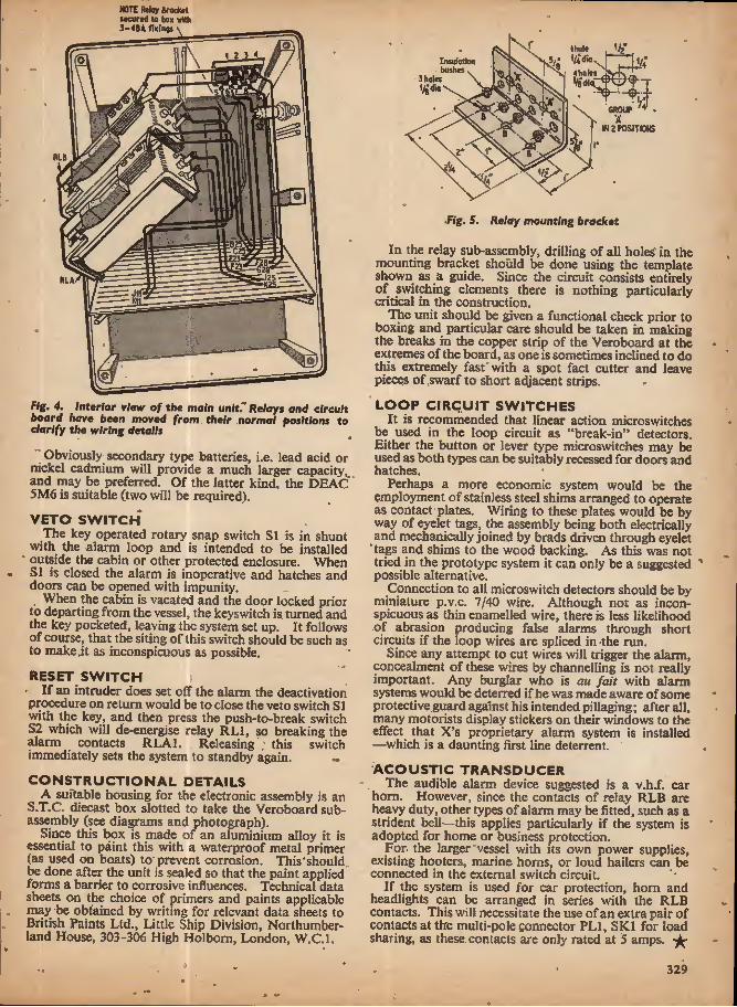
NOTE Rtlqy Brocktl Mcurtd to box w»h
\
RLA JO-
Fig. 4. Interior view of the main unit." Relays and circuit board have been moved from their normal positions to clarify the wiring details
Obviously^ secondary type batteries, i.e. lead acid or nickel cadmium will provide a much larger capacity, and may be preferred. Of the latter kind, the DEAC 5M6 is suitable (two will be required).
VETO SWITCH The key operated rotary snap switch SI is in shunt
with the alarm loop and is intended to be installed " outside the cabin or other protected enclosure. When
51 is closed the alarm is inoperative and hatches and doors can be opened with impunity.
When the cabin is vacated and the door locked prior to departing from the vessel, the keyswitch is. turned and the key pocketed, leaving the system set up. It follows of course, that the siting of this switch should be such as to make .it as inconspicuous as possible.
RESET SWITCH • If an intruder does set off the alarm the deactivation procedure on return would be to close the veto switch SI with the key, and then press the push-to-break switch 52 which will de-energise relay RL1, so breaking the alarm contacts RLA1. Releasing ; this switch immediately sets the system to standby again, ••
CONSTRUCTIONAL DETAILS A suitable housing for the electronic assembly is an
S.T.C. diecast box slotted to take the Veroboard sub- assembly (see diagrams and photograph).
Since this box is made of an aluminium alloy it is essential to paint this with a waterproof metal primer (as used on boats) to prevent corrosion. This'should. be done after the unit is sealed so that the paint applied forms a barrier to corrosive influences. Technical data sheets on the choice of primers and paints applicable may be obtained by writing for relevant data sheets to British Paints Ltd., Little Ship Division, Northumber- land House, 303-306 High Holbom, London, W.C.I.
I hoi* Insutatkm buthss. Jhow 3 holes
Vgdio Vattl
M1 , GROUP IN 2 POSITIONS
■Fig. 5. Relay mounting bracket
In the relay sub-assembly, drilling of all holes in the mounting bracket should be done using the template shown as a guide. Since the circuit consists entirely of switching elements there is nothing particularly critical in the construction.
The unit should be given a functional check prior to boxing and particular care should be taken in making the breaks in the copper strip of the Veroboard at the extremes of the board, as one is sometimes inclined to do this extremely fast with a spot fact cutter and leave pieces of .swarf to short adjacent strips.
LOOP CIRCUIT SWITCHES It is recommended that linear action microswitches
be used in the loop circuit as "break-in" detectors. Either the button or lever type microswitches may be used as both types can be suitably recessed for doors and hatches.
Perhaps a more economic system would be the employment of stainless steel shims arranged to operate as contact plates. Wiring to these plates would be by way of eyelet tags, the assembly being both electrically and mechanically joined by brads driven through eyelet
" tags and shims to the wood backing. As this was not tried in the prototype system it can only be a suggested possible alternative.
Connection to all microswitch detectors should be by miniature p.v.c. 7/40 wire. Although not as incon- spicuous as thin enamelled wire, there is less likelihood of abrasion producing false alarms through short circuits if the loop wires are spliced in -the run.
Since any attempt to cut wires will trigger the alarm, concealment of these wires by channelling is not really important. Any burglar who is au fait with alarm systems would be deterred if he was made aware of some protective guard against his intended pillaging; after aJl, many motorists display stickers on their windows to the effect that X's proprietary alarm system is installed —which is a daunting first line deterrent.
ACOUSTIC TRANSDUCER The audible alarm device suggested is a v.h.f. car
horn. However, since the contacts of relay RLB are heavy duty, other types of alarm may be fitted, such as a strident bell—this applies particularly if the system is adopted for home or business protection.
For. the larger vessel with its own power supplies, existing hooters, marine horns, or loud hailers can be connected in the external switch circuit.
If the system is used for car protection, horn and headlights can be arranged in series with the RLB contacts. This will necessitate the use of an extra pair of contacts at the multi-pole connector PL1, SKI for load sharing, as these contacts are only rated at 5 amps,
329

<-4
%
OKI
r
Garrard SL9S auto transcription turntable
Baker "Major" loudspeaker By M. A. Colwell
Now that stereophonic broadcasts are in full swing in the U.K. (albeit of insufficient quantity and in
a limited number of areas) the manufacturers are jumping on what is now an established bandwagon. The trend to what is termed the "tuner amplifier" is spreading to include stereo.
The problem re-emerges: What is the best unit to buy? This is one question constantly being asked, and it is almost impossible to answer in a few words, because of the many and varied aspects which anyone would look into—not least of these being the capital cost.
Probably the best approach is to take advantage of free entrance facilities offered to that popular event, the Audio Festival and Fair (April 18 to 21), This year the Hotel Russell, Russell Square, London. W.C.I, will open its back doors once again to the hoards of enthusiasts who diligently sort their way through the hotel rooms looking (or should 1 say listening) for the ultimate in sound reproduction.
Among a plethora of equipment, no doubt, the regular visitor will find his pet subjects and the newcomer will be baffled by what may appear to him to be the old game of hunt the thimble. How best can we help him? First of all, decide before you go whether your visit will be confined to certain types of equipment or a general survey of the whole scene. Stamina could be sucked dry if you attempt to take in every single item and demonstration, so that by the time you reach the fourth floor you will be glad to go down again.
If you are set on a particular branch of the audio scene, get a catalogue—it will save quite a bit of shoe
leather. Browse through and make jottings of special interests. See the equipment on the ground floor booths; then after further jottings find your way to the demonstration rooms of your choice. The catalogue will help here again to locate these although, with a little common sense and observation of the direction arrows at strategic points, you should have no difficulty.
Now for the gear! The following is a preview of some of the equipment to be seen. It is interesting to note, during the current national prestige boosting campaign, that imported products are generally more expensive than the "home grown" varieties.
TUNER AMPLIFIERS The "tuner amplifier" mentioned earlier is a term
applied in recent years to equipment combining radio tuning and amplification. The addition of a loud- speaker (or in the case of stereo, two loudspeakers) is usually left to the choice of the user, since there is a wide variety of types at different prices according to one's requirements.
Typical examples are shown by the Sansui range. The one illustrated here is the Model 2000 stereo tuner amplifier which overcomes input matching problems by using a field effect transistor at the front end of the amplifier, inputs are provided for tape head, pick-up, or tuner (internal) for mono or stereo listening.
Later this year the Sansui Model 3000A will be available and offers a higher power output than the current Model 3000. This is also in stereo. The importers are Technical Ceramics Limited.
1 ilU'Cl *+0* « Mooa-ooe Sonsui Model 2000 stereo tuner amplifier
330

Arena stereo tuner amplifier type TISOOF with two HT2I speaker units
Arena of Denmark will be introducing their new stereo tuner amplifier type TISOOF through Highgate Acoustics. Modular construction has been used and it offers an output power of 6 watts per channel for input sensitivities of 10/iV for a.m. and 1/iV for f.m. The picture shows the unit with two matching speakers type HT21.
In addition to their current range of tuner amplifiers, the Trio Corporation of Japan are presenting a new solid state amplifier, the TK150E stereo, through their agents B. H. Morris & Co. (Radio) Ltd., a subsidiary of Lasky's Radio. The price compares modestly with the Supreme I—a 64W per channel stereo amplifier, employing separate bass, mid- and high-range amplifiers, expected to retail at £280,
Armstrong will be showing their Series 400 and Series 27 equipment which includes amplifiers, tuners, and stereo decoders.
When selecting f.m. tuners, look for a.f.c. This overcomes many drifting and fading problems often caused by intervening obstructions between trans- mitter and receiver, or varying atmospheric conditions.
Provisional information obtained from Rogers Developments (Electronics) Ltd., reveals a new f.m. tuner using an f.e.t. front end enabling it to handle large signals without cross modulation, while at the same time being suitable for areas of low signal strength. A.F.C. is incorporated in this model. A multiplex stereo decoder is available as an optional extra. This "Ravensbourne 2" tuner has been designed to match the "Ravensbourne" stereo amplifier.
SPEAKER UNITS Many people have different ideas on what is the best
' speaker. It is largely a matter of personal choice since almost all manufacturers claim the best from their units. Look for a specification with a high flux density magnet and strong rigid frame if going for a moving coil type. Of course, it must have an impe- dance to match the amplifier. Excellent results are obtained with the established Quad electrostatic unit.
Well known names such as Wharfedale, Whiteley, Celestion, Goodmans, and so on, will no doubt attract
Shure M7SE-95G "Guard-a-Matic' cartridge with suspension system
the usual audiences for comparative listening. Of course, they all use different records, pick-ups, and amplifiers, which may give slightly differing results. So it is difficult to make direct comparisons, especially when the rooms are packed with steaming bodies under the floodlights. Perhaps you may be athletic enough to dash from one room to another before the memory of what was heard first has faded.
In between the aural bliss ofSatchmoand (he "1812". take a look at the Titan Minor loudspeaker by Audio & Design, This uses a titanium cone on beryllium copper suspension. It is claimed to reproduce bass more efficiently than conventional types for its size. It is available housed in a cabinet 174i.h * llin x Sfin. Power handling capacity is 15 watts from 40Hz to 22kHz, ± 4dB.
DISC EQUIPMENT Ancillary equipment can be added at various stages
as funds permit, but it is always worth making notes at the Fair for future reference.
Pick-ups have seen some design changes in recent years and it will be interesting to see what is new. Tracking weight is frequently a subject of much confusion. Let it not be assumed automatically that the lighter the stylus pressure, (he better the performance. Similarly with record wear, much depends on the design of the pick-up arm and, even more, on the true running of both turntable and disc.
Where these factors are near perfect, then one can entertain the f ounce pressure, otherwise there is the risk of groove jumping on less accurate turntables and discs. Pick-up arms should be very free moving both horizontally and vertically.
Of unusual design, the Shure M75E-95G "Gard-a- Matic" Hi-Track cartridge, is designed specifically for the new Garrard SL95 transcription turntable (see later). The performance is equivalent to that of the M75E but with a retractile safety suspension system, claimed to provide scratch-proof, bounce-proof opera- tion where floor vibration is a problem. Shure also"
Rogers "Ravensbourne 2" f.m. tuner
as

announce new models in the "economy" range of cartridges. The M31E and M32E have elliptical tipped sty I it for tracking at I-2gm and 2^—5gm respectively.
Audio & Design are introducing a stereo "induced field" cartridge with an output of 0-9mV per cm/sec. It uses an elliptical tipped stylus and is intended for feeding into high impedance inputs.
Cosmocord have developed another version of the stereo compatible cartridge announced last year. The Acos GP91SC incorporates a mono crystal for mono or stereo records. The stylus is suspended on a flexible plastics arm so that it will track stereo grooves, while reproducing a mono signal. It is available in three versions with outputs of200,350, or 640mV at I ^cm/sec.
The Goldring Model GL75 transcription unit, with "free field" stereo magnetic cartridge, maintains the tradition of their using variable speed motor units. The new pick-up arm has a sliding counter balance to cali- brate stylus pressure, and can be raised or lowered hydraulically on to the disc by operating a simple lever,
Garrard equipment at a more modest price include the AP75 single record player, Models SL95 and SL75 auto transcription turntables and the Model 3500 auto turntable, with a low mass pick-up arm, and cue and pause control.
The Model SL95 features "gimbal-type" pick-up arm pivots; the arm has afromosa wood set into aluminium for low frequency resonance damping. The record platform can be pushed down out of the way for single play operation.
Following some suggestions made to B.S.R. they have now superseded the UA70 with-a new Model UA75, which uses a heavy cast alloy machined turn- table.
TAPE RECORDERS Probably the most interesting news in the tape
recording field is from Ferrograph. After 18 years of pounding on their "Tape Deck" (which was originally registered as a trade mark), with very little alteration to the basic design, they have decided to up-date the appearance and construction to the sleek squarish model basic to the new Series 7.
The electronics are similarly up-dated to all. solid state silicon devices, including f.e.t. input stages. The machine can be used horizontally or vertically with easy
Ferrograph Series 7 stereo recorder
Goldring CL7S transcription unit with lever operated pick-up arm
■eh*
access to the electronic units. A time switch is in- corporated for preset starting without the need for it to be previously powered. Several other features are to be found, based on principles in its forerunners. Pre- record facilities for multi-play echo will be found on stereo models, which are supplied with either half- or quarter-track heads.
For another example of a professional studio tape recorder, look out for the BTR4 by E.M.I. Its complementary portable recorder the L4, with film sync facilities is popular for field work among profes- sionals and amateurs.
The latest Brenell deck, Mark 5 Series 3, will be on show; features of this model include a self-compensating braking system, and space for accommodating up to four heads for mono or stereo.
ACCESSORIES Microphones for mono or stereo will be in abundance,
including the MD409, and MD415 by Sennheiser (through Audio Engineering), specially designed for "pop" group vocalists. Both have anti-feedback properties and the bass response is tailored for close microphone technique.
The same Company is also demonstrating a new pair of stereo headphones, HD4I4, for those audiophiles who want personal listening while the wife watches the television.
The well known range of Shure microphones is to be supplemented by the Unidyne IV series. Models 548 (mono) and 548s (stereo). These are designed for professional applications and are fitted with Cannon type connectors.
Finally, a word of advice. Don't arrive at the doors without a ticket or you may not get in. Tickets can be obtained free of charge through your local hi fi dealer or from the organisers of the Audio Festival and Fair, 42 Manchester Street, London, W. 1. (include a stamped addressed envelope).
A 4 4 ■» •s>
4
«
4
•i
332

A
* w
R,.
By G.K. FAIRFIELD
Te most useful test for a transistor is to plot its com- plete range of input/output characteristics. Not
only will this show up the transistor limitations but a great deal of useful information can be derived from a study of the curves.
These characteristics can be produced by making measurements point-by-point using meters to indicate the value of currents flowing. However, this "static" method Is subject to a number of serious limitations, the most important of which is the overheating and possible destruction of the transistor when measure- ments are attempted at the higher current end of its characteristics.
A itiuch better method is to allow the transistor to reach its high current values for only a very short period of time. This is called the "dynamic" method and to use it a cathode-ray oscilloscope must be used to display the transistor characteristics.
This article describes a unit which may be connected to almost any conventional oscilloscope in order to display the transistor characteristics. Single curves can be shown and arrangements are included to permit "families" of ten or more curves to be displayed.
Since the transistor is put through this cycle of applied collector voltage change at a rate of 50 times per second (actually 100 times if the reverse change of Vc Is also used as in Fig. 1) then a clear trace of this characteristic is maintained on the face of the tube. This curve is, of course, applicable to the particular bias current chosen which depends on Vu and the value of bias resistor Rb. To plot a series of such curves it is only necessary to change the value of .Kb in steps, allowing one complete curve to be traced for each fixed value of i?b.
With the simple arrangement of Fig. 1 it is possible to plot /i /Kc curves for common-emitter or common-base configurations by suitable settings of SI. Both pup and npn transistors can be tested by choosing the correct polarity of half-sine wave obtained by the appropriate setting of a reversing switch S2, ^connected to the rectifier Dl,
In order to convert this circuit into a practical arrange- ment it is necessary to add a means of changing the
Vtttta^ewovtftnn wttch r«v«m* ""».wav*form potortty
METHOD OF TESTING The basic technique is shown in Fig. 1. Half sine
waves of voltage are applied to the collector of the transistor from a mains transformer via a load resis- tance Rr. and rectifier Dl. A constant bias current is fed to: the transistor input through switch SI. either to the»|base or the emitter depending upon whether common-base or common-emitter curves are required.
A voltage proportional to the collector current (/c) is developed across the load resistance Rl and applied to the Y-plates of the oscilloscope. The collector voltage Vc: is applied to the X-plates.
Thus as the voltage Kc varies from zero to the peak the^half sine wave so the current /<> changes due to
the j non-linear characteristics of the trknsiston The /c/Vc transistor characteristic is plotted on th£ c.r.o.
Trunslstor uwkrtwt a
o O A.C. O^MAHS o SUPPIY
•o o
SEd OGB
o—AA/* ConjtdM bias corrmt
C,R,0
IX1
the dfsOtov JVftem —-ffp

value of Rb between each curve traced in order that multiple curves can be displayed. It will also be neces- sary to include a cathode follower (or emitter follower) between the X output of the circuit and the oscilloscope in order to avoid loading the high impedance collector circuit. This is particularly important when common base curves are to be displayed. Several different collector voltage and current ranges will be required to accommodate all the transistors that are likely to be tested.
PLOTTING FAMILIES OF CURVES A convenient number of curves to produce a useful
"family" is about ten. These curves will be traced one by one and in order to see them all together on the oscilloscope screen it will be necessary to repeat them fairly regularly (or alternatively a cathode-ray tube could be used having a very Jong persistance phosphor screen). What is required is a rapid single-pole ten- way switch stepping on automatically and continuously to repeat its sequence of ten positions. A Post Office type uniselector switch meets this specification admir- ably. For those not familiar with this device a brief description will not be out of place. Refer to Fig. 2.
The uniselector switch is operated by applying a pulse through the coil which pulls down an armature carrying a claw to engage on, the ratchet wheel. This wheel is attached to the wiper arms of the switch; the fixed contacts are arranged in a semi-circle around the switch arm. Thus each applied pulse rotates the switch arm by one position and engages with the next fixed contact.
Many versions of the uniselector are available and can generally be adapted for our purpose. A number of parallel banks of switch contacts are usually found and three will be required for the Curve Tracer. A standard type of driving coil is one requiring 50 volts to initiate a switch operation. Other types may be found and the driving voltage can be changed or coil rewound to accommodate a different design. The one used in the prototype had a 75 ohm coil.
FINAL CIRCUIT The complete circuit is shown in Fig. 3. A stabilised
power supply is included which uses two 150V refer- ence tubes VI and V2. This supplies the constant voltage source for the base current determining net- work, and also voltage supplies for the cathode fol- lower V3 driving the X-plates of the oscilloscope.
A five-pole, two-way switch S8 enables either a single curve to be traced or a family of characteristics dis- played. (S is for a single sweep display; A is for auto-repetition.) It is convenient to commence our description of the curve tracer by considering switch S8 to be in the "single" position.
The appropriate polarity of base current is selected by switch S5 (generally negative far pnp and positive for npn transistors, although a reverse characteristic may be required sometimes).
The reference voltage is applied to a potentiometer network S6 which allows a selection of input currents covering the range 10mA, 5mA, 2mA, 1mA, 500/t A, and 200/iA, depending on the switch position. Fine control of input current for a single trace is provided by potentiometer VR2, which can be calibrated 0-1, 0-2, and 0-5 if desired, to correspond with the choice of range available.
A meter is also included in the circuit to measure the exact value of current supplied to the base. This has current shunt resistors, wound to give full-scale deflection of 10, 1, and 0-lmA. The current passing
9..: 2 716 2^16 (75 mm) (63 mm)
0
0
X
!
Fig. 2. Side view of uniselector; the armature is at top left above the coil through the meter is direct current; a full-wave bridge rectifier has been included in the circuit. This is to avoid changing connections to the meter when the polarity of the input voltage is reversed by S8. If desired this bridge can be omitted and its place taken by a reversing switch similar to that shown for S2.
The configuration of the transistor undergoing test is selected by means of S4. This permits the current set by VR2 to be applied to the base or emitter depending upon whether it is desired to display the grounded emitter or grounded base characteristic.
The collector voltage is a rectified sine wave supplied via D3 from the 50V secondary of a mains transformer. The maximum amplitude of this sweep voltage is con- trolled by the setting of potentiometer VR1. The polarity of the sweep voltage is selected by S2 to suit either/wp or transistors.
The sweep voltage is also applied via the cathode follower V3 to the X-plate of the oscilloscope tube. A preset adjustment VR3 is provided in V3 cathode circuit to give zero adjustment.
The current axis voltage, representing the change in collector voltage as the transistor collector potential is swept through its range of values, is taken from across a resistor, selected by S3, and fed to the Y-axis ter- minal of the oscilloscope tube. . -
Six current ranges are provided for maximum currents of approximately 5mA, 2,5mA^ SOOpA, 250/fA. lOOpA, and lOpA. depending on the position of S3. Resistor R7 is included to complete the circuit and prevent a surge in current which would otherwise occur each lime S3 was moved to a new position.
When switch S8 is moved to the "auto" position, the uniselector is brought into action. Instead of the value of the input current being set by the position of VR2, a set of resistors, R26 to R34, are sequentially brought into circuit as the uniselector is stepped round to each of its contact positions in turn.
A separate curve is displayed during the time that the uniselector is stationary and a particular resistance
334

PRACTICAL!
VISUAL!
^Wng,
a new 4-way method of mastering
by doing — and — seeing
j p OWN and
HANDLE a
complete range of present- day ELECTRONIC PARTS and COMPONENTS
■9} Q
"SEE
2^ BUILD
and USE
a modern and profes- sional CATHODE RAY OSCILLOSCOPE
!> READ and
DRAW and
UNDERSTAND CIRCUIT DIAGRAMS
T
TOT L7A |C38
"pop I'd. !80e. I'f iK
4 ^ CARRY OUT OVER40 EXPERIMENTS ON BASIC ELECTRONIC CIRCUITS AND SEE HOW THEY WORK . . . INCLUDING . . .
I VALVE EXPERIMENTS i TRANSISTOR EXPERIMENTS AMPLIFIERS OSCILLATORS
• SIGNAL TRACER
9 PHOTO ELECTRIC CIRCUIT # COMPUTER CIRCUIT 0 BASIC RADIO RECEIVER # ELECTRONIC SWITCH # SIMPLE TRANSMITTER
» A.C, EXPERIMENTS i D.C, EXPERIMENTS SIMPLE COUNTER TIME DELAY CIRCUIT SERVICING PROCEDURES
This new style course will enable anyone to really understand electronics by a modern, practical and visual method- no maths, and a minimum of theory—no previous knowledge'required- It will also enable anyone to understand how to test, service and maintain all types of Electronic equipment," Radio and TV receivers, etc.
P OST N 0 W I To: BRITISH NATIONAL RADIO SCHOOL, READING, BERKS. Please ^ j send your free Brochure, without obligation, to; we da not employ representaciyes J
BROCHURE 1 NAME BLOCK CAPS 1 1 I or writ# if yoo prefer not to cut page 1 ADDRESS PLEASE PE 5 1 FREE
335

VARIABLE VOLTAGE TRANSFORMERSi
i 50 AMPS
iAMP ►
£3.10.0.
m
Af- 50;6° (LIGHT SENSITIVE SWITCH OUTPUT VARIABLE 0-260y. j Kkof parts including ORp,2Csd. BRAND NEW * mium Sulphide Photocell, Relay, Keenest prices in the country, | Transistor and Circuit, etc.. 6-12 All Types (and Spares) from . volt D.C. op. price 25/- plus 2/6 t to 50 amp. from stock. I P. & p. ORP 12 including circuit, SHROUDED TYPE I 10/6 each, plus I/-P. & P. I amp. £5. 10. 0. 2.5 amps. I A.C, MAINS MODEL Incorporates £6. 15. 0. 4 amps, £J.' 0. 0.' Mains Transformer, Rectifier and special 5 amps, £9. 15. 0. 8 amps, | relay with 3, 5 amp mains c/o contacts. £14. 10. 0. 10 amps, £18. 10. 0. | Price inc. circuit 47/6 plus2/6P. & P.
TSa"1 "on nmn, "a^n I light source'and pHOTO £25. 0. 0. 20 amps. £37. 0. CELL Mr>iiN.TiMr:|j|
MTCH
PORTABLE TYPE £9. 5. 0.
37.5 amps, £72. 0. 0. 50 amps, ] „ £92. 0. 0. . ' Precision engmeereo „ . , | light source with focusiblc-i OPEN TYPE (Panel Mouotmg) J |ens as5emb|y and ventilated -~ jamp.EJ. 10 0. lamp. £5. I®. 0. | |amp housing, to take MBC bulb. Separate 2.; amps. £6. 12. 6. j ceii mounting assembly for ORP. 12 PORTABLE TYPE 1.5 amp. portable fitted metal voltmeter, lamp, switch, etc. £ Similar toabo^e 2.5 amp. £11.7.6.
100 Wi\n POWER RHEOSTATS (NEW) AVAILABLE IN THE FOLLOWINB VALUES ^ I ohm, 10 a.; S ohm, 4.7 a.; 10 ohm, 3 a.: 'A, 25 ohm,2a.! 50 ohm, 1.4 a.; 100 ohm, I a.; ''lii 250ohm,.7 a.:500ohml.4S a.; 1,000 ohm.
ting i or similar cell. Both units are single hole fixing. Price per pair £2.I5.0. P. & P. 3/6.
HIGH SPEED | COUNTER. 4 figure, 1,000 ohm coil, I 36 48 v. D.C. operation. £3/10/-. P. & ' P. 1/6. 3 figure, 24 v. O.C, £1/12/6.
kW —— j DRY READ SWITCHES. New I special offer of Dry Read Switches half
amp. Contact. Size N x 4 for 10/- 200 mA: 1,500 ohm, 230 mA; 2,500 ohm, .2 a. Diameierl Post Paid. "** ':!in- A" " "" ^iMiMiJTUiwTMlSEllarRTwiTai SO WATT. I ,'5/10/25/501100/250/500/1.000/1.500/2,500 ■ 3 banks of 11 positions plus ■"""
ohm, 21/-. P. & P. i/6. I homing bank. 40 ohm coil. 25 WATT. 10/25/50/(00/250/500/1.000) 1,500/2.500 I 24-36 v. D.C. operation. ohm. 14/6. P. & P. 1/6. ' T«ted^ 22.'fi^phis2/6mmm ^
j ColdPACT hTaVY DUTY Av"-DX~R£UY 12 change over, 30 ohm coil. 7/6 each.
4T
VENNER ELECTRIC TIME SWIT 200-250 v. A.C. 20 amp- contacts twice on, twice off. at any manually pre-set time. Spring'reserve (in case of power cut) fully tested £3/9/6. P. & P. 4/6. Or complete in weatherproof metal case (illustrated) £3/19/6, plus 4/6 P. & P. Can be supplied with solar dial, on at dusk off at dawn. Prices as above. »» ry. ■
ATR-BLOWER ! Highly efficient blower unit fitted with totally enclosed 200/250 v. A.C. SO cycles.
h.p. motor producing 2.000 r.p.m. Outlet 21 " 11, used, but in first class con- dition and tested. Price £3/IS/-. P.& P. 7/(
230/250V. A.C. SOLENOID Heavy duty type, appro*. 3 lbs. pull. Price; 17/6 plus 2/6 P. & P.
12/24V. D.C. SOLENOID Approx. 8 ot. push. Price 8/6 plus I '6 P. & P.
| P. & P. 1/6. 3 lor 20/-. Post paid. j nIckel" -cai^ i um "battery 'Sintered Cadmium Type l'2 v. 7AH. | Size: height 31 in., width 2^ J! Iin. I Weight; approx. 13 oz. Ex-R.A.F.
Tested. 12/6. P. & P. 2/6.
r/Mitf MULTI RANGE METERS New Model U50D Multi tester,
25/000 OPV, mirror scaled with overload protection. Ranges-d.c. volts: lOOmV,
10 5 v. 5 v.. 250 v., 1,000 v.; a.c. volts: 2-5 v.. 10 v.. 50 v., 250 v., 1.000 v.; D.C. current; S /-A. 0 5 MA. 5 MA, S0MA.
1250 MA. Complete with battery and test probe. £7/5/0 post paid. Three other
PRECISION INTERVAL TIMER From 0-30 seconds (repetitive). Jewelled balanced movement. Lever re-set. Operates 230V. A.C. 5 amp. c/o Micro- switch. New. Price 17/6 plus 2/6 P. & P.
| models available from stock. Descriptive I leaflet on request. TH"ro~~piv, Tamp., H/T
| THYRISTOR 400 piv. 8 amp., 28/6 l~220/240~A.C. FAN UNIT"" | 2,300 r.p.m. 6" blade size. CONDENSER 4.000 mfd 25v. 10,6 plus 1/6 P. & P. j Smooth powerful motor
'All metaf construction. CONSTANT VOLTAGE TRANSFORMER Input 185 -250 v. A.C. Output 230 v A.C. Capacity 250 watt- Attractive metal case. Fitted red signal lamp. Rubber feet. Weight 17 lb. Price £1 I1/10/0. P._& P. IS/- . photoTIultiplieb. ——• scdes type 931 A. Complete and divider network. 57/6 ind. P. & P,
-
All metal construction. | Continuously rated. ■ individually tested. J Offered at fraction I maker's price £2.15.0.
' i. S-Jl i^— Type CV337. This sup" sTnGAMO WEST0N with special P.T.F.c. base! _ , , . - ■ - - - ■ Duai range voltmeter. 0-5
j and 0-100 v. D.C. FSD I m/a. In carrying case with test
I prods and leads, 32/6, P. & P. 3/6.
RADIO ALTIMETER _ This precision instrument, built ^ f——■' t—| A.C. CONTACTOR to highest Ministry specification, is based on a 24 v. D.C. ■ 2 make 2 break (or, 2 LOW INERTIA Integrating Motor. The Motor, fitted J c/o.). 15 amp, contacts, with gold brushes and drawing only 800 microamp it|230/240V. A.C. operation. 24 v. D.C.. drives two precision pots with platinum J Brand new. Price 22/6 plus wipers through close tolerance gear-trains, including J I/6P.&P. — miniature slipping dutch, combined with two sufa-I -TS "r' gwnTH miniature pots for calibrating the electrical bridge! 20 Amp LEVER rtlCKO jWllvn circuit. The 3 in. calibrated dial, with a number'Brand new ievcr operated aperture indicating one rev. per revolution of pointer I Micro Switch. 20 amp A.C. with maximum of 5 revs, gives an effective scale length I c/o contacts. Price 4/6 each of approx. 30 in. Offered at fraction of Manufacturer's • plus 1/6 P. & P. S for £1 price, 32/6. P. & P. 6/-. 1 Post Paid.
SERVICE TRADING CO All Mail Orders—Also Callers—Ample Parking Space
57 BRIDGMAN ROAD. LONDON, W.4 Phone 995 1560 SHOWROOM NOW OPEN CLOSED SATURDAY 336
Personal callers only 9 LITTLE NEWPORT ST.
LONDON, W,C.2. Tel. GER 0576
i COLOUR TELEVISION
► MODERN TAPE RECORDING AND HI-FI, by K. Peters. 30/-. Postage I/-.
With particular reference to the PAL SYSTEM
There are 157 diagrams and photographs and 83 illustrations in colour.
by G. N. Patchett 40/- Postage I/-
PAL COLOUR T.V., by Mullard. 12/6. Postage I/-.
PRACTICAL WIRELESS SERVICE MANUAL, Pub. Newnes. 25/-. Postage
ELECTRONIC COUNTING. by Mullard, 27/6. Postage I/-.
BASIC THEORY & APPLICATION OF TRANSISTORS, U.S. Dept. of Army. 12/-- Postage I/-.
RADIO VALVE DATA, 8th ed. compiled by " WW 9/6. Postage I/-.
TRANSISTOR SUBSTITUTION HANDBOOK, Pub. F.Sams. IS/-, Post- age I/-.
THE MODERN BOOK GO. BRITAIN'S LARGEST STOCKISTS
British and American Technical Books 19-21 PRAED STREET
LONDON, W.2 Phone: PAOdlngton 4I8S
NEW FROM OLSON
INSTRUMENT CASES AND CHASSIS,
27 sizes and styles
OLSON ELECTRONICS Ltd. Factory No. 8 5-7 LONG STREET London, E.2 .Telephone 01-739 2343
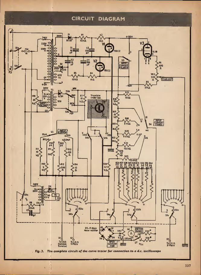
CIRCUIT DIAGRAM
200V + I50Y 2*0V B?ZI2 l-Skft KA
V3 220V O-C Slo 200V *== FSI o-c t50C2
JLcz V2 ^4* =5 400 V2:
6118
55 iwr x x CORREKT POURrr* 600
200V 15002 R3
-w WkA
R4 sA/V
Ikfl VSJ 53V OV 0 500 lyADJUSTl
+(0V -150V 27 KA 2iOV 52a R1S
—V\A 15kfl Transistor undtr t«t VR 200 SJ3K
RI5 50 V kn KA MPH VOIT
R{7
; , R18 NrUT CURRENT COARSF ^kA 6kA
!c«t R20 (OuA CRO 5m A 6kA 54b 02 IOOJMO
250 2.5mA
H22 500 122 KO
R2J 100 Ik R25
vW i^enA K<l> fl27 R28 (129 HJ0RJ1 RJ2 R5J R54 155 60 J5 27,5 15 « M \B i.x BO B24 R12 55 27-5 15 to 64 50 U kO_kfl_kn KA kQ kQ 500
kn
240V
G£XS4( ZIOV
/ S8tt
Z 000
R8 . OV 22 kA A USIO US b A USlc
Sob SBc Sod luF SB«
05-8 fOmA meter Mtt«r ractifitr VB2 RANGE R35
B56* kJy IOOJIA oiVV\i— Npil ToCR.O. CURRENT X-PlaU FINE ToC.R.0. ToC.B.a Common Y-Platt
Tormlnal Fig. 3. The complete circuit of the curve tracer for connection to a d.c, oscilloscope
337
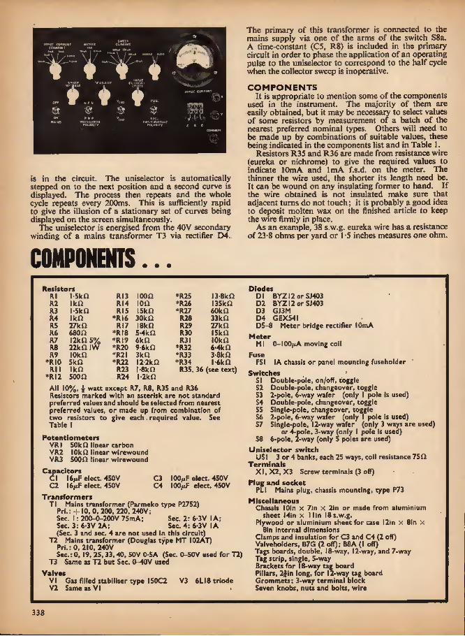
mw cuftftiNT mntn
tww» Tpmumt euUSKTr
on. W h'* T
0k
ixfur ewmeiT
is in the circuit. The uniselector is automatically stepped on to the next position and a second curve is displayed. The process then repeats and the whole cycle repeats every 200ms. This is sufficiently rapid to give the illusion of a stationary set of curves being displayed on the screen simultaneously.
The uniselector is energised from the 40V secondary winding of a mains transformer T3 via rectifier D4.
COMPONENTS...
The primary of this transformer is connected to the mains supply via one of the arms of the switch S8a. A time-constant (C5, R8) is included in the primary circuit in order to phase the application of an operating pulse to the uniselector to correspond to the half cycle when the collector sweep is inoperative.
COMPONENTS It is appropriate to mention some of the components
used in the instrument. The majority of them are easily obtained, but it may be necessary to select values of some resistors by measurement of a batch of the nearest preferred nominal types. Others will need to be made up by combinations of suitable values, these being indicated in the components list and in Table 1.
Resistors R35 and R36 are made from resistance wire (eureka or nichrome) to give the required values to indicate 10mA and 1mA f.s.d. on the meter. The thinner the wire used, the shorter its length need be. It can be wound on any insulating former to hand. If the wire obtained is not insulated make sure that adjacent turns do not touch; it is probably a good idea to deposit molten wax on the finished article to keep the wire firmly in place.
As an example, 38 s.w.g. eureka wire has a resistance of 23-8 ohms per yard or 1 -5 inches measures one ohm.
Resistors Rl l-5ka RI3 I00D *R25 13-8kD R2 IkD RI4 ion *R26 l35kQ R3 i-skn RI5 iskn *R27 60kD R4 IkO *RI6 30k D R28 33kn R5 27kn R17 ISkfl R29 27k n R6 680f2 *Rt8 S-4kn R30 ISkD R7 I2kn 5% *R19 6k a R3I lOkD R8 22kn IW *R20 9-6kD *R32 6-4kD R9 lOkfi *R2I 3ka *R33 3-8kD
*RI0 SkQ *R22 l2-2k£2 *R34 l-6kD Rl 1 IkD R23 l-SkD R3S, 36 (see text)
*RI2 soon R24 l-2kn All 10%, i watt except R7, R8. R35 and R36 Resistors marked with an asterisk are not standard preferred values and should be selected from nearest preferred values, or made up from combination of two resistors to give each. required value. See Table \
Potentiometers VRI 50k O linear carbon VR2 IOkfi linear wlrewound VR3 500n linear wlrewound
Capacitors CI 16uF elect. 450V C3 C2 16/iF elect. 450V C4
I0OmF elect. 450V 100/xF elect. 450V
Transformers Tl Mains transformer (Parmeko type P2752)
Prl.: -f 10, 0, 200, 220, 240V; Sec. 1: 200-0-200V 75mA; Sec. 2: 6-3V I A; Sec. 3: 6-3 V 2A; Sec. 4: 6-3 V IA (Sec. 3 and sec. 4 are not used in this circuit)
T2 Mains transformer (Douglas type MT I02AT) Pri.: 0, 210, 240V Sec.: 0,19. 25,33.40, 50V 0-SA (Sec. 0-50V used for T2)
T3 Same as T2 but Sec. 0-40V used Valves
Vi Gas filled stabiliser type 150C2 V3 6LI8triode V2 Same as VI
Diodes Dl BYZI2 or SJ403 D2 BY2I2 or SJ403 D3 GJ3M D4 GEX54I D5-8 Meter bridge rectifier lOmA
Meter Ml 0-1OO^xA moving coil
Fuse FSI (A chassis or panel mounting fuseholder
Switches 51 Double-pole, on/off, toggle 52 Double-pole, changeover, toggle 53 2-pole, 6-way wafer (only I pole Is used) 54 Double-pole, changeover, toggle 55 Single-pole, changeover, toggle 56 2-pole, 6-way wafer (only I pole is used) 57 Single-pole, 12-way wafer (only 3 ways are used)
or 4-po!e, 3-way (only I pole Is used) 58 6-pole, 2-way (only 5 poles are used)
Uniselector switch US1 3 or 4 banks, each 25 ways, coil resistance 750
Terminals XI, X2, X3 Screw terminals (3 off)
Plug and socket PL I Mains plug, chassis mounting, type P73
Miscellaneous Chassis lOin x 7in x 2in or made from aluminium
sheet J4in x llin 18s.w.g. Plywood or aluminium sheet for case I2in x Sin X
Sin internal dimensions Clamps and insulation for C3 and C4 (2 off) Valveholders, B7G (2 off); B8A (I off) Tags boards, double, 18-way, 12-way, and 7-way Tag strip, single, 5-way Brackets for 18-way tag board Pillars, 2Jin long, for 12-way tag board Grommets; 3-way terminal block Seven knobs, nuts and bolts, wire
338
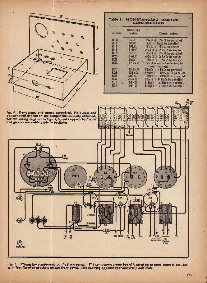
r
Table I; NON-STANDARD RESISTOR COMBINATIONS
Required Resistor value
RIO SkD RI2 500£2 RI6 30k fi RI8 5-4k£> RI9 6kf} R20 9-6ka R2I 3k£2 R22 l2-2k£2
R25 13-8ki2 R26 I35k£2 R27 60k n R32 6-4ki2 R33 . 3-8kf2 R34 l*6k£2
Combination
lOkfl 4- lOkQ in parallel IkD -1- Ikfl in parallel ISkU I5kn in series 2-7kfJ I- 2'7kQ in series I2k£l-1 12kQ in parallel 6-8kSii -i- 2'7kQ in series l-SkO -j- !-Skfi in series l2kO nominal selected by
measurement 56k£2 18kQ in parallel 560kQ 4- 180k£2 in parallel I20kOri- 120k£2 In parallel 33kf2 S^kQ in parallel 8-2ki2 6-8k£2 in parallel 5-6kn r 2-2k£2 in parallel
Fig. 4. Front panel and chassis assembled. Hole sizes and positions will depend on the components actually obtained, but the wiring diagrams in Figs. 5, 6, and 7 appear half scale and give a reasonable guide to positions
SecSOV
T—^v r-A
I
II i if ^ )t4ril3l <12(1111 dOi 9i m-rr^
rii ^ r' rii ri r;i Ri |R(|B l lR, | R iRI 12) i ! 20 1231 1221 1241 iS ItT' I19I 18i L.J L.i L.J l.J L.J L
Chassis
D5-8
SBc SilHlt
Soa-» S8h Sinol
iS^ SBc Slitflci S8« Wipw
S6JWip«r
swr^s. VR3 VRZ VRt
:has is
RI54R)6
Nl It
RZ R4 R6 US)e T2 V3 US)a 12 13 T2 FS VI V2 pin 6
COMMON
PL! Prinyrtn Moins PlUfl
Fig. 5. Wiring the components on the front panel. The component group board Is tilted up to show connections, but is in fact fitted to brockets on the front panel. This drawing appears approximately half scale
339

To 05. , »S2b Wiptr @51 @ NOTE To VW ,-mpontnt sooromountto on Pillar* abovoC5ondC4 Wiptr
Totl 2*0 V
Toll *OV
V; ToS«e Avto TOSBO Auto 50V
« IR- TS rTR TR TR Rtv. IM 129,128 127
mm
-t j vT- ^lr f : L V?,;r.t- It', i ■''■irvi
USf Coi
3 ToS8» Auto ToSSb Auto
ToSBd uS|b
ToSflb Sinjl'
USla
ypql«_ ondVRJ Wipor
US1 e
Wipir tags
\ US1 shown In schtmotic form to elorify wiring
Fig. 6. Top side wiring of the chassis. Each dash on the uniselector represents an outlet tag; the wiper is at the right hand end and coil connections underneath (not visible here). The uniselector is mounted on pillars above the chassis. C3 and C4 are underneath the group board. This drawing appears half scale
PI
[us* • T: —— r-, — —
\3UM}
-Jf | OZ20V ZQOV 0v 5-3VIA
I O200 , fybiVCA
Ll.._ ov 200V A3VIA O+.l0V:
CAoonmust b* insolotod from Chassis v
C3 and C4 to project I through Chassis
Twisted pairs N
f c >-
frz
JoBPn and VR1
P"ToTZPri wand Sib
P ^ Jo 51 ToSZj) [ JoSLji
To S5 To VRJi
02 CZ R3 M C1 R1 R6
Fig. 7. Underside wiring of the chassis. The group board is tilted to show the component wiring clearly
340

Do not allow the wire to become stretched or the resistance will increase per unit length. The values of resistance needed for R35 and R36 will depend on the d.c. resistance of the meter coil. These can be cal- culated from the formula:
Rs = R>i x /m /s — hi
where R* is the shunt resistance required, i?ji is the meter resistance, h is the current scale required, hi is the nominal current rating of the meter (in
this case 100/fA). When making the calculation, resistances are in
ohms and currents in amperes, so allowance must be made for the multiple and sub-multiple signs.
Capacitors C1 and C2 are tubular types and usually insulated. In any case the can of C2 must not be connected to chassis. C3 and C4 are the kind that have to be mounted vertically on the chassis, but here again the can of C4 must not be connected to chassis. It can be wrapped with plastics insulating tape.
The transformers have been selected as being readily available types. TI has three 6-3V windings but only one is used fpr V3 heater. If desired, one of the other 6-3V windings can be used to supply a panel bulb, although this is not shown.
The diodes originally used were AEI types SJ403 but it may be easier to obtain the Mullard BYZI2, which has a substantially higher current rating. •
The wafer switches are pre-assembled types that can be bought for a reasonable sum, but S8 may have to be a slightly more expensive "Yaxley" or "Maka-switch" type.
The uniselector switch is obtainable at many surplus stores. At least three banks are required and a 750
"coil. Check the action of this component before buying to make sure that the wipers ride smoothly through the arc of contacts. This can be done by pressing the armature several times. No parts should be damaged otherwise operation may be intermittent. The uniselector has 25 ways; two series of 11 contacts on each bank are paralleled.
FRONT PANEL Front panel mounting position is given in Fig. 4 with
the wiring below it (Fig. 5). The wiring to S8 has been abbreviated in the interests of clarity, but it should not be difficult to ascertain the appropriate tags if wiring to them is followed in alphabetical sequence, from a pre- determined starting pole, in counter-clockwise fashion.
The "common" terminal on the front panel must make either direct connection to the panel (if metallic), or wired to a chassis connection.
Resistors for connection to S3 and S6 are mounted on an 18-way group tag board, which is fitted to the top of the front panel by right-angle brackets. If the resistors are uppermost, minor alterations to their values can be achieved in situ while the instrument is operating. CHASSIS CONSTRUCTION
Drilling details of the chassis are not given because some adjustment may be necessary according to the components acquired. However, the top and under- side wiring diagrams of the prototype (Figs. 6 and 7) are drawn to scale to give reasonable indication of the positions of the components.
Transformer Tl is mounted so that the turret tags project through the chassis for connection underneath.
Photograph of a family of Icl^c curve* displayed on an oscilloscope
If there are "screen" tags on the transformers these must be connected to chassis.
The main power supply components are mounted on a group tag board under the chassis, while C3 and C4 are fitted (as mentioned previously) to clamps on the chassis. It may prove to be helpful to make the holes for these large enough so that they can project through to about one inch below the chassis top.
A 12-way group board is mounted on pillars above these two capacitors to take the resistors for USlb, Here again, easy access is achieved for alteration of component values.
Finally, before going on to the operation, a word of warning; if it is necessary to make alterations while the instrument is switched on, be careful where you put your fingers and soldering iron. Components on the front panel, as well as T2 and T3 carry exposed live mains.
OPERATION The curve tracer must be used in conjunction with a
directly coupled (d.c.) oscilloscope. The time base must be capable of being switched out of circuit and a d.c. amplifier substituted in its place. Not all oscillo- scopes have this facility and it may be necessary to add an amplifier to the design of the unit. It need only have a modest gain of about a hundred times and quite a small bandwidth and could derive its power from the supply incorporated within the unit.
The type of display obtained is shown in the photo- graph. The illuminated graticule shown in the photo- graph was made from |in perspex placed immediately in front of the oscilloscope screen. Edge lighting through one edge of the perspex by means of a low power bulb will light up the scribed scale lines. This graticule was found useful in calibrating the curves displayed on the screen.
The photograph shows the /c/ Kc characteristic of a low gain pnp transistor having increasing values of reverse.base bias. The ninth and tenth bias values bring the transistor into its cut-off region and conse- quently only a single straight line is traced for both steps.
341

k: <>> v
V
THERE ARE two kinds of electronic music effects circuit: one can be considered as self-contained and self-
generating; the other is dependent on a sound source from a musical instrument.
Sounds made by real cymbals or drums can be modified electronically to produce unusual effects. This is where the Drummer's Whoosh Unit comes in; this will be based on a modified version of the purely Electronic Cymbals described in the present article.
The electronic cymbals unit uses the white noise generator (described ift January) and a power
supply (described in December) with a new filter circuit. The circuits of the white noise generator and power supply are reprinted in Fig. ! so that the whole extent of the circuit involved is realised from the outset.
The power supply is not shown in the photographs as 'it was external to unit, but there is plenty of room to incorporate it in the box if required. Alternatively, the performer may prefer to use dry batteries, so making the unit entirely self-contained and portable.
If required to be housed in the same box as the Drummer's Whoosh amplifier, this can still be done, but we would recommend the constructor to exercise some patience until next month's article appears. The same box can house one white noise generator and filter for both purposes, with modifications to suit the Drummer's Whoosh.
With all these circuits it is necessary to add a power amplifier and, since there is a wide variety of commercial types available, the user should select one that will suit the environment in which he is performing. Tone controls are a desirable facility as will be seen later.
SWITCHED FILTER One white noise generator will provide sufficient
output to operate a set of cymbal effects circuits of different pitches and qualities, giving a set of transis- torised "cymbals" of relatively small size, and at reasonable cost. The cymbals effect circuit is enclosed in the dotted line box in Fig. la.
The 100 kilohm potentiometer VR1 controls the level of the white noise signal fed to the filter circuit. The white noise is filtered and deliberately "coloured" by transformer T1 and capacitor C5, then passes by way of C6 to the base of TR1. This transistor is normally biased into non-conduction by a negative supply applied through RIO. A I-5V or 3V battery will usually suffice here, and serves to prevent a hissing noise between strokes.
342
■
.x"

WHTTE NOISE SENERATM CtMSALS FILTER
ATTACK i DEW SZu 'W +19
toTTv iUl JK2
51 CW 0-003J
Vf Efftcti output
Ih lup (OuF
C4«or ME4I0} Ma tOuF 15)50 0 001tiF O-liiF jntn
JiMOJL _ r TR2
100 VRt 01 =0-01 > to «- <4.7 potnt ' contact < W diode I
DZ- : IStJO^ k C4Z4of ME4103 ♦MJI 00 kA
su R)0 vW wma
negotlvt biu Pulse input
Fig. la. Complete circuit of the cymbals effect unit
POWER SUPPty UNIT
S2b TR4 TR5
FS fi<2 -yVv 0-5A
47a )7v XCH1 115 +l8to D4-7
DDOOQ 24 V i-8D MANS PI NPUT DDOOO CC CI5
tooo 1000 1000
T ^=5 S
ne^
09- t C14 )iiF CIS Cw m VR2 IMF WO- - 2Ma
R(4 \AA/
IMO
Fig. lb. Mod/fled power unit to supply negative bias
In order to simulate a cymbal stroke, a positive pulse must be applied to the circuit via C7, and must be of sufficient magnitude to overcome the negative bias with ease, and cause TR1 to conduct. To obtain a realistic result, this calls for a pulse of at least 6 volts, and indeed any voltage up to about 50 volts may be used.
A simple way to test the circuit would be to connect a I megohm resistor from C7 to the negative supply (common) line, and a Morse key or a push button switch from this input to the 18V to 24V positive supply line. A quick jab on the push button, will charge up C8 via diode pump D2 and D3. C8 will then discharge by way of R8, R9, and TR1.
R8 and C9 act as a filter to reduce "thump" effects. As long as C8 holds sufficient charge, the potential maintained at the base of TR2 will cause TR2 to conduct, and to amplify the signal fed to its base via C6. As C8 discharges, the output from TRI will die away. This output is fed through a further filter-circuit (T2 and CIO) to the effects output jack JK2.
It is worth mentioning that a l|v or a 3V battery connected between chassis and the negative bias line in this circuit will suffer negligible drain, and can be wired in permanently without any need for an on/off switch. A new leakproof battery would be likely to last for a number of years (well beyond normal shelf life), until corrosion sets in.
W«toRN
Better results may be obtained from the circuit by using an adjustable negative bias. The power supply circuit in Fig, lb incorporates a negative bias supply suitable for the purpose- Bias adjustment may be used to control the decay time of the cymbal stroke,
ASSEMBLY AND TESTING Prepare the printed circuit board according to the
design shown (Fig. 2) and assemble parts on it as shown in Fig. 3. Fig. 2 shows the hole-spacing to suit a TOS transistor encapsulation, and this spacing will suit type C424. If type ME4I03 is used, the hole spacing may be made closer to suit the TO 18 Icadout arrange- ment of this transistor.
When assembly of the components on the cymbal- effects circuit-board is complete, wire it up to a white noise generator, d.c. power supply of 18V to 24V and an audio amplifier or mixer unit. Temporarily connect the positive supply line to the junction of D2 and D3. Switch on and adjust VR1 and the controls on the amplifier so that the sound of the white noise generator comes from the loudspeaker as a loud hiss.
Disconnect the positive line from D2 and D3. The sound should die away fairly rapidly. With some transistors, the sound will fade to a very low level without the need for a negative bias supply; others may need the application of a negative base bias via RIO,
343
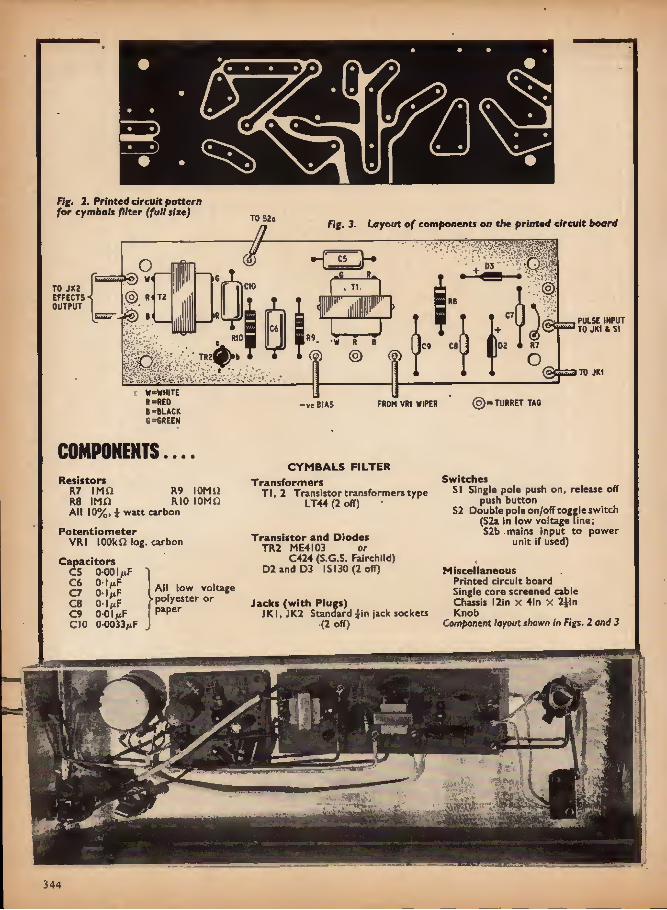
1
a
Fig, 2. Printed circuit pattern for cymbals filter (full size) TO 52a
o §) W
TO JK2 EFFECTS Ol R OUTPUT
© e ^6
Hi T2 h
41
Fig. 3. Layout of components on the printed circuit board
■ v.'
W-WHITE R=RED B-BLACK G=6REEN
•-[ C5
CIO . Tt
JJ
H
PULSE INPUT TO JK1 & 51
RIO W R 8 02 « R7 C9 C8 (?) © (9) o
TO JK1
-v« BIAS FROM VR1 WIPER (§)= TURRET TAG
COMPONENTS....
Resistors R7 IMD R9 lOMil R8 IMO RIO 10MO All 10%, ^ watt carbon
Potentiometer VRI 100klog. carbon
Capacitors C5 0-001/xF ' ^7 n 'ow voltage S 2:1^ >poly««ter or C9 0-OI^F PaPer
CIO 0-0033^F
CYMBALS FILTER Transformers
Tl, 2 Transistor transformers type LT44 (2 off)
Transistor and Diodes TR2 ME4I03 or
C424 (S.G.S. Fairchild) D2 and D3 IS 130 (2 off)
Jacks (with Plugs) JKI, JK2 Standard ^-in jack sockets
(2 off)
Switches S! Single pole push on, release off
push button S2 Double pole on/off toggle switch
(S2a In low voltage line; S2b mains input to power
unit if used)
Miscellaneous Printed circuit board Single core screened cable Chassis I2in x 4in X Jyin Knob
Component layout shown In Figs. 2 and 3
f.
344

COMPONENfS...
POWER SUPPLY UNIT
Resistors rii 47a Ri3 i-sa RI2 47a RI4 IMH 10%iW All 5% 3W,-wirewound except RI4
Potentiometer VR2 2Ma linear carbon
Capacitors CM 1,000/iF elect. 25V C12 1,000/iF elect. 25V CI3 1,000/iF elect. 25V CI4 IfiF polyester 160V CIS SO/xF elect. 25V C16 1 polyester 160V CI7 0*I/xF polyester 160V
Transformer T3 Mains transformer, charger type. Pri. 240V mains; sec. 0-I7V IA
Transistors TR3 XCI4I TR4 AC 176
Diodes D4 to DI0 DDOOO (Lucas) (7 off) or IS!30
Switch S2b (see under Cymbals Filter)
Miscellaneous FSI Fuse 0-5A with holder LPI Neon panel indicator with resistor Printed circuit board 6in x 2iln Heat sink for XCI4i Knob
Component foyowt given in December 1967 issue
WHITE NOISE GENERATOR
Resistors Rl 4-7ka R4 2-7ka R2 4-7ka R5 I Ska R3 39k O R6 IkQ All 10%, y watt carbon
Capacitors Cl 25p.F elect. 25V C2 IO/aF elect. 25V C3 100/iF elect. 12V C4 lOfxF elect. 25V
Transistor and Diode TR1 C424 (S.G.S. Fairchild) or ME40I3 Dl Point contact diode, any noisy
type, such as sold for crystal receivers
Miscellaneous Printed circuit board 2in x 2in
(Bonanza Board) Connecting pins and wire
Component layout given in January 1967 issue
Components for cymbals filter given on previous page
in order to achieve a quiet background in between strokes, and a l^V battery is usually quite sufficient.
If the positive line is quickly touched on to the junc- tion of D2 and D3 a few times in succession, a sound similar to a cymbal stroke may be heard, but may not be very realistic at this stage, as adjustment of VR1 and the tone controls of your amplifier will have a considerable effect on the output qualities.
VR1 must not be set too high, or the effect will result in a continuous roaring or crackling sound. This is because the white noise is fed to the base of TR! at a high level to overcome the negative bias. Turn down VR1 to a level somewhat below that at which the roar occurs. If, now, the cymbal strokes tend to have a somewhat crackly ending, VRl must be set to an even lower level to give a smooth finish to each stroke.
VARIATIONS The circuit is not by any means restricted to the
component values given. By changing the values of C5 and CIO the cymbals pitch may be altered; the use of different transformers will give yet further ranges of effects. A choke or other inductor could be used in place ofT2, and the output taken from the collector of. TR1 by way of an 01(«F capacitor.
Changing the values of C7, C9, and R9 will affect the "attack" and "decay" characteristics of the circuit.
although the combin< not be reduced to a poi collector-dissipation free air).
value of R8 and R9 should it which would result in excessive
TR1 (rated about 2C)0mW in
METHODS OF OPERATION For manual operation, the simplest method Is to
connect a 1 megohm resistor (R7) from C7 to the negative (common) supply wire, and apply pulses to this, input from the 18V to 24V positive supply point by use of a Morse key or a'push button switch. The final circuit shown in Fig. I performs the same function.
The circuit may also be operated electronically by connecting C7 directly to an electronic switching circuit (via JK1) such as a slow running multivibrator (for automatic "repeat" effects); a ring counter (for rhythm effects) or an electronic keying circuit. In all these circuits the pulse may be supplied from the collector of the switching transistor concerned. If using the multivibrator described in the article on a Simple Rhythmic Control Unit (February issue) JK1 would be connected to the collector of either TR I or TR2 in that circuit.
The "Cymbals" circuit may be used very successfully with an electronic rhythm machine or a rhythm genera- tor. An adaptation of the circuit may be used for beat group sound effects; this will be described next month in the Drummer's Whoosh Unit.
345

AL* BOOK
BEGINNER'S GUIDE TO ELECTRICITY By Clement Brown Published by George Newnes Limited 185 pages, 7^ln. x 5in. Price 15s
Anyone starting a career or hobby in electronics might be put off by the title of this book when
looking for an elementary guide. In order to under- stand and appreciate the technicalities of even the most simple of electronic circuits, one should have, or be able to grasp, the fundamentals of basic electricity. It comes at a time when more and more schools and training colleges are giving courses in the subject, and is therefore suitable for almost any beginner from 14 to 40 years of age.
It is written in an intelligently straightforward style that will complement course lectures and lab. experi- ments. Of necessity it is not by any means exhaustive but will certainly cover in adequate terms the theory to be found in advanced level G.C.E. and O.N.C, courses. Electronics is not strictly introduced until Chapter 7, and even then in only basic form.
Technical terms tend to baffle many beginners, but here they will find explanations easily understood, and related to everyday electrical appliances and electronic circuits. Valve and transistor theory is included. The relationship between theory and domestic and industrial applications provides a suitable balance to a book that could otherwise have been rather dry reading.
The final chapter gives some guidance for those wishing to make a career in this fascinating activity.
M.A.C.
ABC's OF TRANSISTORS By George B. Mann 112 pages. Price 20s
F.E.T. CIRCUITS By Rufus P. Turner 160 pages. Price 25s
ABC's OF VACUUM TUBES By Donald A. Smith ' 128 pages. Price 20s
BRIDGES AND OTHER NULL DEVICES By Rufus P. Turner 143 pages. Price 26s Published by W. Foulsham & Co. Ltd. All 8fin x Si in
Another four titles in the impressive catalogue of Foulsham Sams educational primers in an
expanding technology. All four of the books present their subjects with a minimum of mathematics apart from the last title which sets out the necessary bridge equations happily, without qualification, Treatment of the subject matter is succinct and well illustrated and all
four volumes are recommended as beginning texts for those anxious to be taught the rudiments of electronics.
ABC's of Transistors deals simply with the basic physical and electronic features of these devices and analyses their action in oscillators and amplifiers. Practical servicing and testing procedure of these circuits are also discussed.
F.E.T. Circuits is an excellent book for those readers who like their electronics practical. From a brief introductory chapter on structure and performance you are launched into the whole gamut of circuit applica- tions of this versatile high impedance device: trans- mitters, receivers, test gear, control circuit, each one in effect a potted constructional project as all component and performance details are given.
ABC's of Vacuum Tubes. Dealing in the main with the construction and action, both dynamic and passive, of valves from the diode to the multigrid family- Biasing and classes of operation are covered and the final two chapters deal with miscellaneous and special purpose valves. Altogether a painless introduction to valve technology.
Bridges and Other Null Devices. Measurement is fundamental to all sciences. In electronics the bridge type circuit predominates in this application and this book sets out (o explore its various forms for specific measurement purposes. From basic bridge circuit theory the reader is introduced to most of the equipment found in a test gear laboratory. Although the Illustra- tions are of American equipment, the principles and measurement capabilities are universal.
G.G.
COLD CATHODE TUBES By J. B. Dance, M.Sc. Published by Jllffe Books Ltd. 125 pages, 8fin x 5^in. Price 3Ss
n a world largely dominated by the semiconductor, glass enveloped devices are becoming increasingly
rare. But one group of tubes seems to have gained a new lease of life due, indeed, to the general expansion of electronic techniques brought about by soIid_ state devices. For visual displays of data, or indication of the operational condition of circuitry, there is no real substitute for the cold cathode tube. This can be a simple neon lamp (which may double as a voltage regular), or a rather more complex numerical or character indicator tube. The orange-red glow of neon is the outward manifestation of electronic sophistry, as we well know.
But the cold cathode tybe family includes the well known G.M. tube for nuclear radiation detection, stepping tubes for counting circuits, and other important specialised types, besides.
The electronics enthusiast who is "genned up" on solid state may be lacking in knowledge about cold cathode tubes. He can now find the basic facts of gas discharges and straightforward descriptions of those tubes he is most likely to encounter in modern electronic apparatus in this book. Some experiments with neon diodes and trigger tubes are described and there are many practical circuits which show typical applications of the various devices. A good practical introduction to the subject, with a minimum of maths.
D.D.R.
346

Transistor Amplifier
DESIGN 4»S:S
By A.Foord
Negative feedback occurs when a proportion of the output voltage of an amplifier is fed back to
the input in such a way as to reduce the overall gain, so that the gain with .feedback is less than the gain without feedback. Feedback can be used to:
(1) Give a predictable mid-band gain, the greater the amount of feedback the less sensitive the amplifier is to changes of transistor character- istics.
(2) Increase bandwidth or to give a shaped fre- quency response curve which depends almost solely on the passive components forming the feedback network, and does not depend on an accurate knowledge of transistor, parameters (which may vary between one specimen and the next of the same type).
(3) Increase or decrease input or output impedances; - by using different feedback arrangements it is
possible to obtain input or output impedances higher (or lower) than those normally associated with transistor stages. In particular it is possible to arrange for a high input impedance and a low output impedance, so that amplifier stages can be cascaded without interaction.
(4) Reduce the distortion which normally occurs in the final stages of an amplifier, where current and voltage swings are highest.
BASIC PRINCIPLE Any study of negative feedback begins with a func-
tional block diagram, Fig. 4.1. The circuit has two signal paths; the forward path,
which is usually an amplifier and contains all the active devices, is marked with its voltage gain A; the feedback path B which has a gain less than unity. The bar above the symbol A indicates that there is a phase reversal in the amplifier, while B represents the fraction of the output voltage fed back to the input.
The phase reversal to obtain negative feedback occurs in the amplifier; the arrows in the block diagram reassure us that the feedback is in fact negative. In a simple case this is obvious, but for more complicated arrangements a check will ensure that we do not accidentally use positive rather than negative feedback.
Take a simple example, Fig. 4.2. Without feedback we require an input of O-IV to the amplifier for an output of — 10V. If negative feedback is added making B equal to 0-1 times, 0-IV is still required at the input of the amplifier itself to obtain an output of -10V.
The input to the addition point,needs to be HV, so that when the — 1-0V is added to the input we are left. with 0-1V to give an output of !0V. The overall gain with feedback is now
G' = —^ = -9-1 times
The negative feedback has reduced the gain from its open loop value of 100 times to a closed loop gain of 9-1 times, therefore the closed loop gain is approxi- mately l/B times (1/5 = 10). /
A more detailed examination will show that the gain with feedback is approximately l/B provided the closed loop gain is much less than the open loop gain, Fig. 4.3.
Starting at the input to the amplifier (call this K) then the output of the amplifier is A F, the voltage fed back is A VB, and the input h V + A VB. Then the overall gain with feedback is given by
, _ Fo ' AV _ A _ -1 Fi FT A VB I + AB I . _
A + B-
If B is much greater than XjA (i.e. A is much greater than 1/5) then C = 1/5.
Vnm/IV — lOV V\ 0-1V -100 9 kit
Ikfl
0-1 9 + 1
f/f, 4.1. Functional dia- gram of an amplifier with negative feedback path
Fig. 4.2. 4simple example of negative feedback
Zvs V, a v + +^d)
Fig. 4.3. Voltage relation- ships between the amplifier and the feedback circuit
347

X100
fRtOUENCY
i FUEQUEBCY
Fig. 4.4. Gain and phase characteristics which woufd cause Instability
FREQUEKCr
SATISFACTORY
FREQUENCY
UNSATISFACTORY
Fig. 4.5. instability shown by "ringing" cycles
1k,o
IOrA
Fig. 4.6. The practical example of a high gain amp/ifier with feedback re- sistor and "antl-ringing" capacitor C
Therefore, the ideal gain with feedback (C) is equal to 1/5, if the gain without feedback (A) is much greater than I /B.
To confirm this, compare the results using the accurate formula and the approximate formula; drop the minus phase sign since we are interested in magni- tudes rather than the phase reversal we know occurs in the amplifier.
Actual closed loop gain G' = ~—^ I - /!
Ideal closed loop gain G = ^ D
Calculation will show that, if the required gain with feedback is one tenth of the gain without feedback, then we do not need to use the accurate formula, since errors in assuming G equal to 1 IB are small enough to be discounted.
STABILITY Having assumed that the design of the amplifier is
such that the feedback will always tend to reduce the gain, but unfortunately this will not always be so, any practical amplifier will contain reactive elements which will introduce a phase shift in the signal as it passes through the amplifier (quite apart from the 180 degree mid-band phase shift required to obtain mid-band negative feedback). The gain and phase characteristics of the amplifier might appear as Fig. 4.4.
Above a certain frequency /, gain falls and an extra phase lag is introduced. If we applied 100 per cent negative feedback to an amplifier with this character- istic, to give an overall gain of unity, the amplifier would oscillate.
While there is still greater than unity voltage gain around the loop, there is an extra 180 degrees of phase shift to cause the feedback (which was negative below /) to become positive at /'. The system would there- fore oscillate at the frequency/'.
Designing for stability is complicated when a con- siderable amount of feedback is applied. Instability in a feedback amplifier is shown by a peak in the frequency response curve and ringing on a square wave signal (see Fig. 4.5).
Feedback over one or two stages is normally safe, although later on, when considering the use of 100 per cent feedback to raise input impedance, a non-mathe-
348
matical approach will be applied to the stability problem. For most purposes, it is in order to see that the frequency response curve does not have a peak of more than a couple of decibels in it, and that the square wave response is satisfactory, i.e. free from ringing effects.
The photographs show results obtained with a high gain amplifier, this had a gain of 1,000 times (60dB) without feedback, and a gain of 10 times (20dB) with feedback (see Fig. 4.6).
Photo A shows the leading edge of the 1kHz square wave input; photo B shows the ringing on the output waveform without the capacitor C, and this was con- sidered unsatisfactory. The capacitor was adjusted in value to obtain the acceptable response of photo C. Since for clarity the photographs only show the leading edge of the square wave, the time scale was extended to show the leading edge more clearly. The capacitor was increased to reduce the bandwidth to 20kHz which increased the rise time to that shown in photo D.
Feedback around one stage only is called local feed- back, and since only the common emitter stage pro- vides a phase reversal of its output signal with respect to its input, it follows that local feedback can only be applied around the common emitter stage.
There are two basic ways of applying feedback to the common emitter stage; one arrangement is con- sidered next, and the other is dealt with later, in the section on virtual earth amplifiers.
SERIES LOCAL FEEDBACK Referring to Fig. 4.7, the resistor Rk in series with
the emitter accounts for the applied feedback, this resistor enables a feedback voltage Vt proportional to, load current, to be fed back in series with the input voltage Vu The base-emitter voltage of the transistor is reduced by the feedback so that Fhe is less than Vu
If Rk is small and of the same order of value as the internal emitter impedance rn (say 100 ohms or so), then the amount of feedback is small. Distortion is slightly reduced and bandwidth is increased very slightly, at the expense of a small decrease in gain. If Rk is large then the gain is given by
„ Vo Ri. T'i ~ RF,
The input impedance Is given by
Zi — hicRii
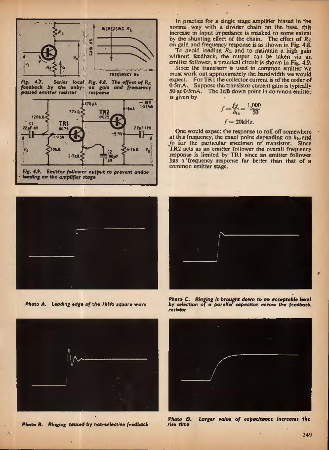
(NCR ■ASIN0
'
FREQUENCY Hz Fig. 4,y. Series local Fig. 4.8. The effect of Re feedback by the unby- on gain and frequency passed emitter resistor response
-i«v i-SlmA At/OyA
w< TR2 HnA
tZOkn (JC75 TRi OC75
C1 22yf 6V
—Oh ZZJJF 12V Hh- -5-3V -1-5V
iOkn VTkll 2-7kfl IQOur
I Fig. 4,9. Emitter follower output to prevent undue loading on the amplifier stage
In practice for a single stage amplifier biased in the normal way with a divider chain on the base, this increase in input impedance is masked to some extent by the shunting effect of the chain. The effect of Jts on gain and frequency response is as shown in Fig. 4.8.
To avoid loading fit and to maintain a high gain without feedback, the output can be taken via an emitter follower, a practical circuit is shown in Fig, 4.9.
Since the transistor is used in common emitter we must work out approximately the bandwidth we would expect. For TR1 the collector current is of the order of 0-5mA. Suppose the transistor current gain is typically 50 at 0 5mA. The 3dB down point in common emitter is given by
r h 1,000 ] Ate 50
/= 20kHz.
One would expect the response to roll off somewhere at this frequency, the exact point depending on Ate and ft for the particular specimen of transistor. Since TR2 acts as an emitter follower the overall frequency response is limited by TRI since an emitter follower has a'frequency response far better than that of a common emitter stage.
Photo A. Leading edge of the IkHz square wave Photo C. Ringing it brought down to an acceptable level by selection of a parallel capacitor across the feedback resistor
Photo D. Larger value of capacitance increases the Photo B. Ringing caused by mm-te/eetfve feedback rise time
349

The results without feedbaciic (C2 connected) and with feedback are:
Gain without feedback Bandwidth Input impedance Output impedance Maximum output
310 times = 50dB 30kHz IkCl 300 a I*5V r.tn.s. no load 500mV r.m.s. into IkH
The frequency response was measured under no load conditions at lOOmV r.m.s. L)p to 50kHz or so, the amplifier will provide 500mV r.m.s. into I kilohm, but above this frequency the emitter follower current gain starts to drop and the waveform distorts, so that 500mV would only be obtained without distortion into a load greater than 1 kilohm.
The gain without feedback appears high until we remember that the collector load is 27 kilohms rather than the 1 kilohm or so we would expect for another common emitter stage and a high gain transistor is being used.
Gain with feedback =
Bandwidth = Input impedance = Output impedance — Maximum output
27 10 times ~ 20dB
68kHz 7k Q 3000 500mV r.m.s. into IkO
(up to 50kHz)
The actual measured gain was 19*5dB, which is probably an error in measurement or tolerances on the collector and emitter resistors. Since the open loop gain is 30 times the closed loop gain, one might expect the gain of 20dB to be independent of variations in characteristics between one OC75 and the next, although the bandwidth might alter slightly.
Although the gain has been reduced by a factor of 30 times, bandwidth has only increased twice. Series local feedback is often used inside another overall feedback loop, where a predictable stage gain is required rather than an unpredictable (though higher) gain.
With an input impedance of 7 kilohms and an output impedance of300 ohms, these amplifiers can be cascaded
flz
At A?
CAIN as
A1 A2 40
A1 00 A2 20
12dQ/OCTAVE i
WB/OCTAVE a
\ FREQUENCY V
Fig. 4.10. Combining Fig. 4.11. The response of two identical amplifiers each amplifier is added
to give overall response
GA H GAIN
LI I fig. 4.12. Equivalent cir- cuit of a transistor looks like that of a transmission line at high frequencies
Fig. 4.13. A single CR conversion of Fig. 4.12
without interaction. Bandwidth is also extended at the low frequency end, but since this is within our control (coupling and decoupling capacitors) the main benefit of this type of negative feedback is the pre- dictability of mid-band gain rather than the small extension of bandwidth.
TRANSFER FUNCTIONS The amplifier can be represented as a block, so that
two amplifiers in series could be represented by adding the two separate gains in decibels (see Fig. 4.10).
Ai = 10 times — 20dB A2 = !0 times = 20dB
A, Ao = 100 times = 40dB
Working on the frequency response curve and adding decibels this would result in the response shown in Fig. 4.11.
SLOPE 6«19/OCTAVE (20d3/DECA0E)
(Ht t FREQUENCY
101
Fig. 4.14. Approximating the frequency response, then deriving the accurate response (solid line)
1
At
AZ
- ATPROXIMA IE CUR VE •
«
AC CURATE CU RVE— V k ri s K
50 2 5 10 20 FREQUENCY (kHz)
Fig. 4.15. Summing the response of two amplifiers in cascade
too
350

Where each amplifier was 3dB down (at /), the response is now 6dB down (for two identical amplifiers), and the new 3dB down point is lower down at fi, as one would expect. The slope of the curve for a single amplifier is approximately 6dB per octave, and for two amplifiers in series this will be 12dB per octave.
In the equivalent circuit of a transistor (Fig. 4.12) it appears as a transmission line for high frequencies, but as a first approximation it can be considered as a single CR network, Fig. 4.13.
Taking the CR network or single time constant on its own, at low frequencies C has a high impedance and Vo — V. At a frequency when C has a reactive impedance equal to R, Vo is 3dB down with respect to V, and continues to fall at 6dB per octave (20dB per decade) with increasing frequency, as in Fig. 4.14.
The solid line curve is the accurate frequency res- ponse, while the dotted line is the straight line approxi- mation. The point / where the impedance of the capacitor is equal to the resistor is called the "turnover" or break point. The maximum error between the accurate and straight line approximation is 3dB which occurs at the break point. In practice the approximate curve is drawn; /is 3dB down, 0-5/and 2/are IdB below the approximate curve; the accurate curve is drawn from this information.
For two amplifiers in cascade the procedure just outlined is shown in Fig. 4.15. The bandwidth of the two amplifiers in series is almost identical, but the ultimate slope is now 12dB per octave rather than the 6dB per octave for a single common emitter stage.
RELATION OF RISE TIME AND BANDWIDTH
A square wave can be considered as the sum of a number of harmonically related sine waves; these include a fundamental sine wave at the bcisic repetition frequency and frequencies of three, five, seven times, and so on (odd harmonics of the basic frequency).
If a square wave of 1kHz is fed into an amplifier.with a sharp cut off at I -SkHz all the harmonics are filtered out, leaving only the 1kHz fundamental, Fig. 4.16.
If the response of the amplifier is extended to 20kHz the output would consist of the fundamental and harmonics up to 19kHz. Harmonics at 21kHz,
-TLT - INCUT
fig. 4.16. A square wave signal can, be filtered to give the fundamental frequency only
nr- INCUT uuirv. 1kHz Iktiz
fig. 4.17. Increase In the rise time of the square wave by loss of harmonics
23kHz upwards would be attenuated according to the roll-off of the amplifier response curve. The square wave would hardly be degraded at all, since the ampli- tudes of these harmonics (relative to the fundamental) are small. The loss in harmonics increases the rise time of the square wave. Fig. 4.17.
To determine the bandwidth of an amplifier we would feed in a square wave with a rise time better than we would expect the amplifier to handle, and measure the degradation on the output.
Suppose our square wave had a rise time of 5/iS and after passing through the amplifier this was degraded to 25/48, then our amplifier has a rise time of \/(252—52) or 24-5/is and its bandwidth is given by:
This method is only an approximate means of deter- mining bandwidth, it would tell us if our amplifier had a bandwidth of 20kHz-or 10kHz, but we could not rely on discriminating between bandwidths of 20kHz and 17kHz.
However the edges of the square wave do represent the type of signals present in a transient, Which simple sinewave testing cannot do, so that we can see immedi- ately any instability or excessive overshoot or ringing in the amplifier. The disadvantages are that we do need a square wave of good rise time, and an oscillo- scope capable of showing it. Next month: Negative feedback applied to prac- tical circuits.
BETTER SOUND The BBC announces that four programmes in a new
series "Better Sound" will be broadcast on Fridays at 7.00-7.30 p.m. in Study Session, Radio 3 from May 3 to 24. Listeners will be invited to send questions of general interest, or requests for more information on particular topics covered in the series and these will be dealt with in two extra programmes which will follow the repeat of the series later in the year.
The series will be repeated on Radio 4 on Saturday mornings at 11.00-11.30 a.m. from August 17 to September 14. There will be no programme on August 31 (Bank Holiday weekend), but there will be . two additional pro- grammes on Saturdays, September 21 and 28.
Each programme will focus attention on one area of this wide field. A number of topics (e.g. microphones, loud- speakers, stereo) will therefore be treated in more than one programme. Advice on particular makes cannot be given and the construction and repair of equipment will not be dealt with.
Programme 1: Transmission and reception of radio, including stereophonic broadcasting. Explanation of AM and FM, etc.
Programme 2: The nature of sound, and room acoustics, with demonstrations of the effect of different placings of microphones and loudspeakers.
Programme 3: The reproduction of music in mono and stereo; U fi equipment.
Programme 4: Tape-recording for the amateur. The diagrams in the Study Notes (BBC Publications,
2/6 plus 5d postage) will be helpful in following the broad- casts and the explanations in the text of the basic principles of the transmission, recording and reproduction of sound in mono and stereo will be useful for reference, particularly for the less knowledgeable listener.
351
^>_ A A 1-5k«z/^ \ j
■,?Tsr>- r~| n ZOkHz^ I i
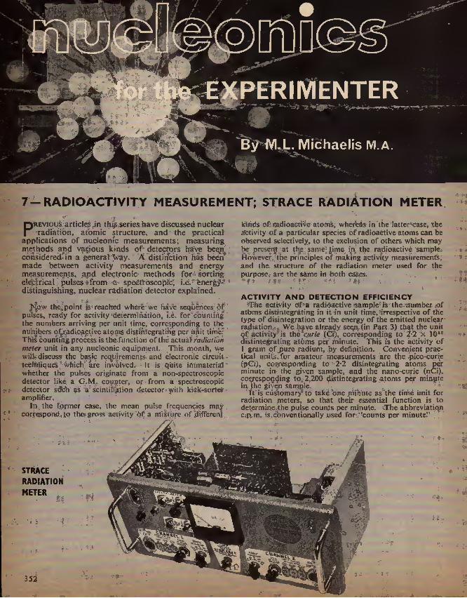
7-RADIOACTIVITY MEASUREMENT; STRACE RADIATION METER
P"revioqs articles Jn this series have discussed nuclear •radiatibn, atomic structure, and the practical-
applications of nucleonic measurements; measuring methods and various kinds of detectors have been considered in a general way. A distinction fias been made between activity measurements and energy measurements, and electronic methods for sorting elep|rical pulses from 4" speettoscojpic, i.e. energy- distinguishing, nuclear radiation detector explained.
Now the point |s reached where we have sequences of pulses, ready for activity 'determination, i.e. for cbuniing the numbers arriving per unit time, corresponding to the numbers of radioactive atoms distiftfegratihg per unit time. This counting process is the function of the actual radiutiun meter unit in any nuclconic equipment. This month, we will/ discuss the basic rcqu1remcn|.s- and clectronie circuit techniques which are involved. It is quite iftfmaterfal whether the pulses originate from a non-spectroscopic detector like a G.M. counter, or from a spectroscopiC detector such as a Scintillation detector with kick-sorter amplifier.
In the former case, the mean pulse frequencies may correspond tq the? gross activity of a nlixiurc of different
kinds of radioactive atoms, whereas in the latter case, the activity of a particular species of radioactive atoms can be observed selectively, to the exclusion of others which may be present at the same lime in. the radioactive sample. However the principles of making activity measurements, and the structure of the radiation meter used for the purpose,- are the same in both cases.
ACTIVITY AND DETECTION EFFICIENCY The activity of a radioactive sample is the .number of
atoms dtstintegrating in it in unit time,irrespective of the type of disintegration or the energy of the emitted nuclear radiation. Wc hayc already seen, (in Pact 3) that the unit of activity is the curie (€«),_ corresponding to Z-2 X lO13
dislintegrating atoms per minute. This is the activity of 1 gram of purc radium, by definition. Convenient prac- tical units* for amateur measurements are the pico-curie (pGi), corresponding to 2-2 disintegrating atoms per minute in the given sample, and the nano-curie (nCi). corresponding to 2,200 distintcgrating ;atoms per minute in Jhc given sample.
"It is customary to take one minute as the time unit for radiation meters, so that their essential function is to determine the pulse counts per minute. The abbreviation c.p m. is conventionally used for '-counts per minuter
STRACE RADIATION METER
352,
St
.
Or- O.
>4 -■ V-
'• -j- V-..

It is not possible to calibrate a radiation meter directly in pCi or nCi, but only in c.p.m. This is because the ratio of c.p.m, to pCi depends on the numerical detection efficiency of the radiation detector employed. The ratio is 2*2 only if every disintegrating atom in the radioactive sample produces an electrical response pulse in the de- tector. This is rarely the case in practice; a greater or smaller proportion of the radiations will miss the detector, so that the ratio c.p.m./pCi is practically always con- siderably less than 2-2. Of course, it is the aim of any detector and sample arrangement to achieve as high a numerical detection efficiency as possible. This is also referred to as the geometry factor.
TWO EXAMPLES Two examples will make this point clear. In the first case, consider a radioactive sample lying on
a large flat radiation detector, i.e. G.M. counter. The nuclear radiations may be emitted in any direction by chance. Thus, on the average one half of them will fly upwards or obliquely upwards, and miss the detector. The other half will travel downwards or obliquely down- wards, and enter the detector to produce a pulse. The ratio c.p.m./pCi would be J-I in this case.
In the second case, consider the sodium iodide crystal of pur scintillation detector (see Part 5), with the radio- active sample placed at the bottom of the axial sample well. Nuclear radiation emitted in almost any direction will then strike the crystal, so that we would expect very nearly the ideal value of 2-2 for the ratio c.p.m./pCi.
In practice, we actually find values considerably smaller than I-l and 2*2 for the respective cases, because two further factors reduce the detection efficiency. Firstly, some quanta of radiation may be absorbed within the sample, or other insensitive material, before reaching the sensitive detector region. Secondly, some quanta may pass straight through the detector without getting absorbed to produce a pulse. Thus the ratio c.p.m./pCi is only about 0-1 for a liquid sample in the MuIIard MX124/01 G.M. counter tube specified for our equipment (see Part 4). The scintillation detector possesses a considerably greater detection efficiency, under some conditions approaching closely to the ideal value of 2-2 for the ratio c.p.m./pCi.
RADIOACTIVE DECAY Since the activity of a given radioactive sample is a
statement of the number of atoms disintegrating per unit time in that sample, this activity must necessarily diminish with the progress of time, because the number of atoms left over is continuously decreasing. For any given species of radioactive atoms, the activity is strictly pro^ portional to the number of atoms of that species which are present in the sample, i.e. the rate of decay is directly proportional to the amount present.
This is the basic characteristic of any exponential process (the rate of fall of the voltage across a capacitor discharging through a resistor is always proportional to the actual voltage left across the capacitor at the instant considered, or the rate of growth of a sum of money on compound interest is at all times proportional to the accumulated capital). Thus the activity of a simple radioactive sample decreases exponentially with time. This is a very important principle, known as the radio' active decay law.
Different species of radioactive atoms decay at different rates, which are specifically characteristic of the respective species, just as different capacitor/resistor combinations discharge at different rates according to the produce of capacitance and resistance (time constant) of the circuit.
DECAY HALF-LIFE For radioactive samples, we specify a decay half-life.
This is the time taken for one half of a large initial number of atoms to disintegrate. If we wait a further equal period of time, one half of the remainder will have disintegrated, i.e. the number of atoms still left over is halved during each successive half-life period. The process theoretically never goes to completion. The smaller the number left over becomes, the greater the random departures from
One of the rotemeter modules of the STfiACE Radiation /Meter
smooth exponential decay. Ultimately, when only one atom is left over, it is inherently impossible to predict how long it will continue to remain intact.
A similar indeterminacy prevails already at the outset, when we had a very large number of atoms. If we were to single out any particular atom for close observation, there is no way of predicting, in which successive half-life period it will meet its fate. This is subject to pure chance^ Thus whilst we can be pretty sure that almost exactly one half of a large number of atoms will disintegrate in a half-fife period, we are unable to determine in advance which particular atoms will belong to the decaying half,
STATISTICAL FLUCTUATIONS The inherent unpredictability of the lifetime of any
single radioactive atom introduces random fluctuations in the predictable mean behaviour of a large number of similar atoms. If the smooth exponential decay law would ideally demand that n atoms should disintegrate in a given sample within a certain time of observation, then the actual number of atoms observed to decay within that lime will in all probability differ from n. It may be smaller or larger. If we repeat the experiment numerous times under identical conditions, the average of all observa- tions will approach ever more closely to «. Regarding the discrepancies of individual results, we will find that these average to ± V"- This is called the mean uncertainty of the count n.
As far as practical measurements are concerned, this means that if we want our activity reading to be reliable to within 1 part in n, we must count at least n2 pulses before we stop the counter and divide by the total time taken. Otherwise random fluctuations will exceed our tolerance limit and the readings are meaningless to the envisaged accuracy.
It is common practice to specify four accuracy classes, namely 1, 5, 10, and 20 per cent. These correspond to desired reliabilities of 1 part in 100, 20, 10 and 5, so that we must respectively count at least 10,000, 400, 100 or 25 pulses.
Note carefully that it is solely the total pulse count which determines the statistical accuracy, quite irrespective of the time taken for clocking-up this count. The radiation meter must simply be left running until the required number of pulses have arrived, and if this takes a very long time in the case of low activities, the circuits must be designed with adequate long-term stability.
RADIATION METER TIMING The relationships explained in' the previous section
dominate the design of practical radiation meters. In the case of digital counting, there are few .basic problems as far as long-term stability is concerned. Professional equipment often adopts count liming here. In other
353

nATEMETER PfilNTEO CIRCUIT eOARO 4X6 PULSE
AMPLIFIER PULSE INTEGRATOR
VOLTMETER EXPANDER I II W.
I PHASE INVERTER RW 47011 wm " IOUP S22 Z-Tk/l ^ VR2 R2B RZ7 4-7U1 4700. IOpiF 2-ikQ
TIX ikil
£ TR7 BSTS3 TR8 0ST5J TR9 IZCOpF 057 53 HI 22uns
Q
BAY20 27kQ - - 4 k JU- : :2-bwi TR5 0C465
IKO VR1 zsknji- iKA TR4 0C465 B4Y20 i5Mn 2-2Mn 5-6 WO TR1 «465 TR2 85*51 TR6. 0C108
im R6 5-6kfl ■VA— 7i" JTOUJ Iku kll PUMP <85 ?2'2(.n INTEGRATOR 05 BAYZO TR3 00465
11
J-5kfl Wrl
07 ZS - -BZ ' ' BAY 20 Riiazfkn BAY27 530kfl Z-Zkfl Ikft s-zkn 4-7kA 10 oo VR4 Z-SMO ifei
<R4 - ro* ZSOkfl cf ts
k -Mi 2-2KA BAY20 SZkft
\-H-V 857 S-Sktl# /
0'1PF R58 (OKU
-Wx—1 I JSkft CM 40)17 tOOX
MICRBFOIL r O-luf F.S.O. TO PIP OENERATOR AND/OR DKITAL COUNTER 09 BAY 20 K_ 5 528 PU<4> WW S2AO) 5 WIT
')P12 IS) n.s<6> 2 VOLT 5 VOLT POSITIVE POSITIVE JL A. PULSE INPUTS FROM RAOIATBN DETECTOSS
NEGAilVt r 21V T UNSTASILISEO : i: ALI6WHENT CONTaOLS
VR5 CALIBRATE,RANGE US TRIGGER VR6 ZERO, RANGE 3 ZERO, BANGE 1/2 VR7 ZERO,RANGE 4/5 CAUBRATE, RANGE 1/2
RANGE SWITCH I K» I I PULSE/MINUTE J ^0 f "8 7.5.0, OF HI 5 50,000J
Fig. 7.!. ST RACE RAD/AT/ON METER; Circuit diagram of the ratemeter module
words, the time taken to achieve a predetermined count is measured. Suppose we desire a statistical accuracy of 1 per cent. The clock will then be zeroed and the counter set to 10,000. The clock is then set running forwards and the counter backwards. When the counter reaches zero, it stops the clock automatically.
_ In the case of analogue counting, more special con- siderations are required. We remember that analogue counting establishes the activity reading as the voltage developed across a capacitor. Each pulse pumps a definite small electric charge into the capacitor, whilst the capacitor at the same time discharges through a precision resistor. The resulting voltage across the capacitor is directly proportional to the rate of arrival of the pulses. This voltage will fluctuate in a random manner, due to the random fluctuations of the pulse race. The meter reading thus fluctuates over a certain range of the scale, instead of being steady.
RATEMETER TIME-CONSTANT Consider the lowest range of the ratemeter in our
STRACE equipment, which is 100 c.p.m. for full-scale deflection. The design figure is the 5 per cent statistical accuracy class, which calls for 400 pulses in the "counting time". These take four minutes to arrive at 100 c.p.m., so that the product of the integrating capacitor value (vF) and its discharge resistor (megohms) should be 240 seconds.
If the value of the capacitor is kept constant, but the value of the discharge resistor halved, then a given pulse rate will produce only half as great a meter deflection. The full-scale deflection c.p.m. value is thus doubled. But the statistical accuracy is unchanged, because although the time constant has been halved, the rate of arrival of the pulses for full-scale deflection has been doubled, so that the same number of pulses arrive within the time-constant period.
In general, this leads to a simple rule. The various desired c.p.m. ranges are. obtained by switching corre- sponding different discharge resistors across the same integrating capacitor, whereby the same statistical accuracy
is then obtained on ail ranges. This is most fortunate, since only one capacitor is thus required. The capacitor must be of immaculate quality, above all, it must have very low leakage and excellent long-term capacitance stability, so that it is rather expensive. Precision resistors are much cheaper, and only these are required in quantity according to the desired number of ranges.
STRACE RATEMETER MODULE Fig. 7.1 shows the complete circuit of the ratemeter
module for the STRACE radiation meter unit.* The components within the broken-line rectangle are
accommodated on a 4in x 6m printed circuit board. Layout is in no way critical.
Almost any silicon np/i transistors are suitable for TR2, 7, 8, 9, and almost any silicon p/tp types for TR1, 3, 4, 5, provided collector voltage ratings are at least 12V working in all cases, TR6 may be any small germanium pup audio power transistor, e.g. OC72 is also suitable. The small diodes may be any silicon type with small self- capacitance and at least I00V p.i.v. rating. D7 is a 5V miniature Zener diode, D8 is a 500mW dissipation (at least} 12V power Zener diode. Resistors should be ±10 per cent, except those connected to S2B, which must be ±5 per cent, or better still ± I per cent. The specified prototype semiconductors are all S.T.C./Intermetal types, but in no way imperative.
TR1 is a polarity inverter for those radiation detector types feeding negative pulses to PL!, DI suppresses positive pulses or components while D2 prevents overload of TR1 on excessive negative pulse amplitudes at PLI. TR2 is the main pulse amplifier stage. It is fed at the base with the positive output pulses from TR1 collector, as well as with the inputs of positive-pulse radiation de- tectors connected to PL2 and/or PL3. D9 is included here to prevent short-out of PL3 input by the low- impedance output .stage of a detector connected to PL2, thus it is not necessary to disconnect the cables of switched off detectors.
* (Ref to Fig. 2.1 for block diagram of STRACE Radiation Meter Unit.)
354

next month!
THRESHOLD LEVELS VR1 is the collector load of the main pulse amplifier.
It is preset to give the response threshold levels marked against PL1 to PL3. D4 suppresses negative pulses or components at TR2 base, and D3 prevents overload of TR2 if excessive positive pulse amplitudes are applied to
. PL2 or PL3. The diodes D1 to D4 associated with TR1 and TR2 thus make the circuit very tolerant of large differences in input pulse amplitudes. The perforrhance is still perfect even if the pulses fed to PL1, PL2 or PL3 are ten times larger than the specified threshold values. Gain controls are thus not necessary on the front panel.
PULSE EXPANDER TR3 is a driver emitter follower, to feed the pulse ex-
pander from the necessary low source impedance. The pulse expander TR4/TR5 is a transistorised equivalent of the valve-operated pulse expanders already introduced last month in the gamma ray spectrometer kick-sorter amplifier.
TR4 normally rests cut-off, and TR5 conducting. When a trigger pulse arrives via C4, the roles of the two transistors change over for a time determined by C9 or CIO in conjunction with R19. Thereafter, the transistors revert to the resting state of their own accord. The duration of conduction of TR4 in response to each trigger pulse from TR3 is independent of the form or duration of that trigger pulse, being determined solely by C9, CIO and R19.
PUMP INTEGRATOR During each conduction pulse of TR4, a definite quantity
of positive charge is pumped via D6 and R20 into the integrating capacitor C14. S2B switches the appropriate discharge resistor across C14, to establish the different c.p.m. ranges as discussed previously. The other wafer, S2A" of the range switch selects C9 or CIO for determining the pump pulse duration. On the lowest range (f.s.d. - 100 c.p.m.), C9 is in circuit and gives a long pump pulse, whereas the short pump pulse with CIO is used for all other ranges.
The value of the integrating capacitor CJ4 is 40^F, and the net value of the discharge resistance (R32, VR4 and the input impedance of the read-off voltmeter TR7, 8. 9) is 4 megohms for both range I and range 2. Due to the different pump pulse duration, range 1 is 100 c.p.m. and range 2 is 250 c.p.m. for full-scale deflection, so that the statistical accuracy is in fact somewhat poorer than 5 per cent on range I but somewhat better than 5 per cent on range 2 and all other ranges. This is a compromise made to avoid unduly high values for C14, or unmanageably high circuit resistances.
READ-OFF VOLTMETER The read-off voltmeter for the integrator capacitor C14
comprises the remainder of the circuit on the right of Fig. 7,1. The design figure is for a ImA fsd meter and/or chart recorder connected to the output.
TR7, 8, 9 are cascaded current amplifiers to reduce the current drain on the integrator capacitor C14 for the voltage read-off process. VR3 sets a d.c. bias voltage in series with CI4 on ranges 1 and 2, to overcome the silicon threshold of TR7, 8, 9. TR6 is in parallel with VR3 and possesses a compensating temperature co- efficient to cancel thermal drift of the threshold level of TR7, 8, 9. TR6 must be positioned close to TR7, 8, 9 to sense the same temperature as the latter components.
VR6 and VR7 fulfil the same function as VR3 for the other ranges. VR5 sets the meter sensitivity for all ranges. D8 stabilises the supply voltage for all stages. D7 limits the maximum voltage developed across C14, to prevent damage to the meter MI or TR7, 8, 9 if the range switch is set to a range too low in relation to the input pulse rate.
Next month: The remaining circuitry for the STRACE radiation meter; this includes the pip generator, audio amplifier, and power unit.
Build this
Radio-Controlled
MODEL
BOAT
^vV-V
*51
a &
$ • •
A pleasure to construct and a joy to run, this 34in kit-built diesel-powered high speed craft carries a multi-channel control system which will make it the king-pin of any water on which it is sailed. Incor- porates proportional rudder and progressive throttle control for good manoeuvrability, with simultaneous or one-at-a-time operation of these systems. Full how-to-build Instructions, with details of transmitter and receiver (including control gear). Begins in next month's issue. Don't miss it I
Other Constructional Projects include:
DRUMMER'S WHOOSH UNIT CAMERA TRIGGER
PRACTICAL
ELECTRONICS
JUNE ISSUE ON SALE FRIDAY MAY 17 Order your copy now!
355

SEMICONDUCTOR
6-OTHER SEMICONDUCTORS
By 6. |. KING
Thi| serifes/S^tso far dealt with the more commonly used memodri of the semiconductor family, and in
this concludina article the aim is to consider briefly some of the more recent developments using semi- conductor materials.
TUNNEL DIODE The tunnel diode action differs considerably from
the conventional diode. The main difference concerns the reverse current characteristic which reveals that the diode is highly conductive for all values of reverse voltage (see Fig. 6.1): the forward current changes with increasing forward voltage.
Initially, the forward current increases with forward voltage in the normal way up to curreot /p due to forward voltage Vp. As the voltage is further increased the current starts to fall, and subsequently falls into a deep valley before it starts rising again to follow the normal diode forward characteristic. This is called a negative resistance characteristic because it is opposite to ordinary resistive current flow.
FORWARD ^ CURRENT
REVERSE VOLTACE
MICH CONDUCTIVITY"
/ N MlfiATIVE / NORMAL RESISTANCE / FORWARD
CHARACTERISTIC / CHARACTERISTIC
FORWARD VOLTACE*
| REVERSE ♦CURRENT
Fig.6.1. Characteristics of tunnel diode. Note the negative resistance zone and that high conductivity occurs in the reverse direction
f—"W-* f go ADJUST L
+ B,AS< _L
lau Jr 1-5V (QUARTZ TUNNEL
CRYSTAL DIODE
Fig. 6.2. Simple crystal-controlied oscillator using tunnel diode
The depletion layer (potential barrier or "space charge" region) is much narrower than in conventional junction diodes due to a very high concentration of p- and n-type Impurities in the basic crystal. Hence, electrical charges are encouraged to traverse the junction by an action called tunnelling.
In most applications the tunnel diode is biased so that the operating point is established in the negative resistance region, and it is suitable for use as an ampli- fier, detector, oscillator, high-speed switch and rectifier. This latter aspect may seem strange in view of the high reverse conductivity.
Conventional rectifiers are arranged for substantial current flow in the forward direction, but extremely small in the reverse direction. Tunnel rectifiers, on the other hand, are arranged for substantial reverse current flow at very low voltages and much smaller forward current due to the negative resistance effect. This means that tunnel diodes can provide efficient rectification at much smaller signal voltages than con- ventional rectifiers, but note the reversed polarity requirements (for which reason they are sometimes called "back diodes").
Their amplifying attributes are particularly valuable at microwave frequencies (above 300MHz) due to low noise operation and low current demands.
Stabilisation assumes great importance when the device is arranged as an amplifier, for it has a great tendency to-oscillate more freely than to amplify without oscillating. This results from the wideband negative resistance characteristic which, when the amplifier is really well designed, can yield gain over a bandwidth in excess of an octave without variable tuning.
There is no trouble at all in getting a tunnel diode to oscillate, even with only a fraction of a volt bias. A basic oscillator circuit using a quartz crystal as con- trol is given in Fig. 6.2. This yields a high range of harmonics because as the diode oscillates it swings continuously from the low voltage state, through the unstable negative resistance region to the high voltage state.
INTEGRATED SCREEN TRANSISTORS Early transistors were troubled with a high output/
input feedback capacitance which called for neu- tralising techniques in high gain amplifying applica- tions to prevent the amplifier from changing into an oscillator.
In ordinary transistors the unwanted feedback capacitance stems from the comparatively large bonding areas required for the emitter and base leadouts. The
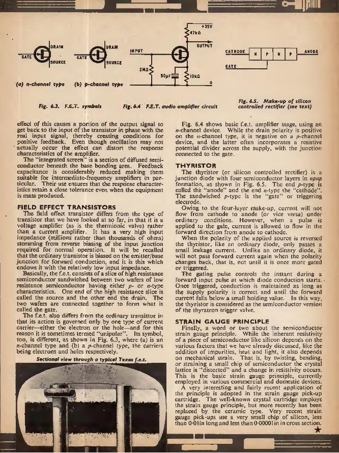
■f 35V 47ka
^ORA.H ^-JORA'K SATE vU BATE I" D ^■^SOURCE ^-^JSOURCE
(a) n-channel type (b) p-thannel type
OUTPUT INPUT rr
2MO< Kb
•lOka T 1 0
CATHODE N P N P ANODE
6 ATE
Fig. 6.3. F.E.T. symbols Fig. 6.4 F.E.T. audio amplifier circuit Fig. 6.5. Make-up of silicon controlled rectifier (see text)
effect of this causes a portion of the output signal to get back to the input of the transistor in phase with the real input signal, thereby creating conditions for positive feedback. Even though oscillation may not actually occur the effect can .distort the response characteristics of the amplifier.
The "integrated screen" is a section of diffused semi- conductor beneath the base bonding area. Feedback capacitance is considerably reduced making them suitable for intermediate-frequency amplifiers in par- ticular. Their use ensures that the response character- istics retain a close tolerance even when the equipment is mass produced.
FIELD EFFECT TRANSISTORS The field effect transistor differs from the type of
transistor that we have looked at so far, in that it is a voltage amplifier (as is the thermionic valve) rather than a current amplifier. It has a very high input impedance (millions rather than thousands of ohms) stemming from reverse biasing of the input junction required for normal operation. It will be recalled that the ordinary transistor is biased on the emitter/base junction for forward conduction, and it is this which endows it with the relatively low input impedance.
Basically, the f.e.t. consists of a slice of high resistance semiconductor sandwiched between two wafers of low resistance semiconductor having either p- or /;-type characteristics. One end of the high resistance slice is called the source and the other end the drain. The two wafers are connected together to form what is called the gate.
The f.e.t. also differs from the ordinary transistor in that its action is governed only by one type of current carrier—either the electron or the hole—and for this reason it is sometimes termed "unipolar". Its symbol, too, is different, as shown in Fig. 6.3, where (a) is an n-channel type and (b) a p-channel type, the carriers being electrons and holes respectively.
Sectional view through a typical Texas f.e.t.
Fig. 6.4 shows basic f.e.t. amplifier stage, using an //-channel device. White the drain polarity is positive on the //-channel type, it is negative on a //-channel device, and the latter often Incorporates a resistive potential divider across the supply, with the junction connected to the gate.
THYRISTOR The thyristor (or silicon controlled rectifier) is a
junction diode with four semiconductor layers in fip/ip formation, as shown in Fig. 6.5. The end //-type is called the "anode" and the end //-type the "cathode". The sandwiched p-type is the "gate" or triggering electrode.
Owing to the four-layer make-up, current will not flow from cathode to anode (or vice versa) under ordinary conditions. However, when a pulse is applied to the gate, current is allowed to flow in the forward direction from anode to cathode.
When the polarity of the applied source is reversed the thyristor, like an ordinary diode, only passes a small leakage current. Unlike an ordinary diode, it will not pass forward current again when the polarity changes back, that is, not until it is once more gated or triggered.
The gating pulse controls the instant during a forward input pulse at which diode conduction starts. Once triggered, conduction is maintained as long as the supply polarity is correct and until the forward current falls below a small holding value. In this way, the thyristor is considered as the semiconductor version of the thyratron trigger valve.
STRAIN GAUGE PRINCIPLE Finally, a word or two about the semiconductor
strain gauge principle. While the inherent resistivity of a piece of semiconductor like silicon depends on the various factors that we have already discussed, like the addition of impurities, heat and light, it also depends on mechanical strain. Thai is, by twisting, bending, or straining a small chip of semiconductor the crystal lattice is "distorted" and a change in resistivity occurs. This is the basic strain gauge principle, currently employed in various commercial and domestic devices.
A very interesting and fairly recent application of the principle is adopted in the strain gauge pick-up cartridge. The well-known crystal cartridge employs the strain gauge principle, but more recently has been replaced by. the ceramic type. Very recent strain gauge pick-ups use a very small chip of silicon, less than 0 01 in long and less than 0 00001 in in cross section.
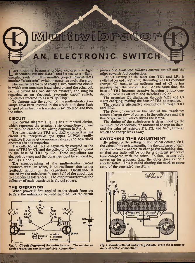
E=
DwQ
d
o o
A ELLCTRONIC SWITCH
Last month's beginners project explored: the light dependent resistor (l.d.r.) and its use as a "light-
operated switch". This month's project demonstrates another "electronic" switch, namely the multivibrator.
The multivibrator is basically a two transistor circuit in which one transistor is switched on and the other off, i.e. the circuit'has two distinct "states", and may.be regarded as an electronic two-pole on/off switch, sometimes referred to as a "Flip-Flop".
To demonstrate the action of the multivibrator, two lamps have been inserted in the circuit and these flash on and off as first one transistor is switched on and then the other.
CIRCUIT The circuit diagram (Fig. 1) has numbered circles,
which represent the terminal strip connections; these are also indicated on the wiring diagram in Fig. 2.
The two transistors TR1 and TR2 employed in this circuit are inexpensive npn types 2N2926 readily available from most components shops, and advertised elsewhere in the magazine.
The collector of TR1 is capacitively coupled to the base of TR2 by Cl, and the collector of TR2 is coupled to the base of TR1 by C2. These capacitors are electrolytic types and the polarities must be adhered to, see Figs. 1 and 2.
The cross-coupling of the multivibrator circuit produces what, in effect, is an oscillator, due to the feedback action of the capacitors. Oscillation is started by the unbalance in each half of the circuit due to component tolerances. The output waveform at the collector of each transistor is almost square.
THE OPERATION When power is first applied to the circuit from the
battery the unbalance between each half of the circuit
LP2 (0W1
BY1 TR2 TRi SOLF WuF
2K29Z6 Vfv.. »■«*««• T™'!?st0f e ■ eoll«rtor w wm b-boM
2*2924
pushes one transistor towards current cut-off and the other towards full conduction.
Let us assume at the start that TRI and LP1 is switched on andTR2 is off; the voltage at TRI collector charges Cl because the collector end of Cl is less negative than the base of TR2. At the same time, the base of TR2 becomes negative bringing it into con- duction from its off state and switches LP2 on.
The capacitor Cl discharges through VR1 and C2 starts charging, making the base of TRI go negative.
The result is alternative conduction through TRI and TR2.
The flow of current in the base of the transistors causes a larger flow of current in the collectors and it is this larger current which drives the lamps.
The timing of the switch-over is determined by the values of the capacitors, the amount of charge on them, and the value of resistors Rl, R2, and VR1, through which the charge leaks away.
SWITCHING TIME ADJUSTMENT By adjusting the setting of the potentiometer VRI,
the value of the resistance affecting the discharge of each capacitor can be altered to change the switching time, so that one bulb will be on for a different period of time compared with the other. In fact, as one bulb comes on for a longer time, the other does so for a shorter time.' This is called altering the mark-to-space ratio of the generated waveform.
s'xsV/g 1
SOFTWOOD BASE TSBYi
TH2 TRI VM
I ' 1 J
LP2
Fig, I. Circuit diagram of the mu/tivibrotor. The numbered circles represent the terminal strip connections
Fig. 2 Constructional and wiring details. Note the transistor and capacitor connections
358

Low consumption 6V lamps are used with a current rating of 0-06A (60mA), but lamps rated at 0*1 A (lOOmA) will work just as well. Higher ratings should not to be used unless the transistors are changed for higher current types.
USING PNP TRANSISTORS If the reader wishes to use pup transistors the
capacitor polarities must be changed round, i.e. the positive ends are connected to the bases of the transis- tors. Also, the battery connections will have to be reversed, i.e. negative terminal connected to the lamps.
CONSTRUCTION Commence the construction by cutting a softwood
baseboard Sin x Sin X fin. The next stage is to wire the 12-way terminal strip before mounting this in position on the baseboard. A plastics sleeved link wire should be inserted between terminals 1 and 12. The two resistors R1 and R2 should be positioned between terminals 3 and 6; 8 and 10.
The outer leads of the subminiature potentiometer VRI should be carefully bent so that they can be inserted in terminals 6, 7, and 8, see Fig. 2. The electrolytic capacitors C1 and C2 are positioned in terminals 2 and 10, 3 and 11. It is important that C1 and C2 are wired to the correct terminals; reference should be made to Fig. 2.
Finally, before mounting the terminal strip on the baseboard, the transistors should be mounted on the strip, see Fig. 2. Particular care should be taken to ensure that the transistor leads are wired to the correct terminals, as they can be damaged if wired incorrectly.
FINAL ASSEMBLY The terminal strip and m.e.s. bulb holders can now be
screwed to the baseboard, see wiring diagram for relative positions. The terminal strip should be checked against the wiring diagram and screwed to the baseboard with two |in No. 4 countersunk woodscrews. The m.e.s. bulb holders are screwed to the baseboard with four fin No. 4 countersunk wood screws.
COMPONENTS ...
Resistors Rl 2-2kO R2 2-2kC2 l0%< i carbon
Potentiometer VRI lOkfi linear subminiature preset
Capacitors Cl, 2 50/iF electrolytic, 12V (2 off)
Transistors TRI, 2 2N2926 (2 off)
Lamps LP1, 2 6V 0-06A (60mA) (2 off)
Miscellaneous BY I 9V type PP9 battery One 12-way plastics terminal block Two m.e.s. bulb holders, batten mounting Wooden baseboard Sin x Sin x ^in Two miniature crocodile clips or battery connectors Six fin No. 4 countersunk wood screws Plastic covered, single cqre copper wire Total cost £t approx.
A lead from terminal 11 is taken to LP2 bulb holder. Two leads are taken from the other connecting screw and wired to terminal 8 and LPl bulb holder, see Fig. 2. The other connecting screw of LPl should be wired to terminal 2.
Finally, the battery leads should be wired in circuit. The negative lead is taken from terminal 1 and clipped on the battery negative connector by a miniature crocodile clip. The battery positive lead is taken from terminal connecting both lamps together,
•The crocodile clip acts as a simple switch if removed when not used. All the wiring should be given a final check before making the final battery connection. The multivibrator lamps will start flashing or switching on and off as soon as the supply is connected.
AH components wired to the terminal strip. Note the link wire
m
^43
Fixing a connecting lead to one of the m.e.s. bulb holders
The completed multivibrator
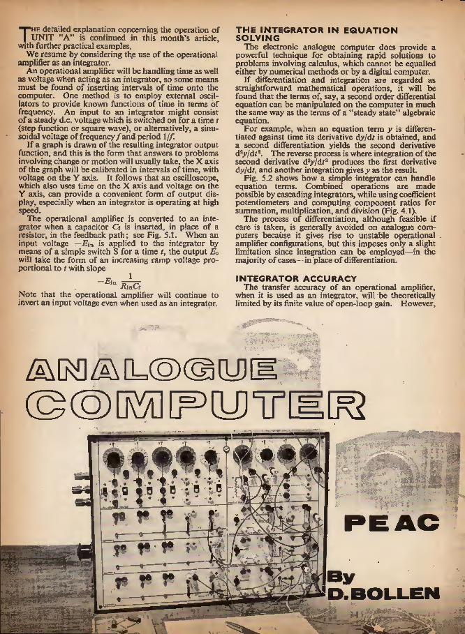
The detailed explanation concerning the operation of UNIT "A" is continued in this month's article,
with further practical examples. We resume by considering the use of the operational
amplifier as an integrator. An operational amplifier will be handling time as well
as voltage when acting as an integrator, so some means must be found of inserting intervals of time onto the computer. One method is to employ external oscil- lators to provide known functions of time in terms of frequency. An input to an integrator might consist of a steady d.c. voltage which is switched on for a time t (step function or square wave), or alternatively, a sinu- soidal voltage of frequency /and period 1//.
If a graph is drawn of the resulting integrator output function, and this is the form that answers to problems involving change or motion will usually take, the X axis of the graph will be calibrated in intervals of time, with voltage on the Y axis. It follows that an oscilloscope, which also uses time on the X axis and voltage on the Y axis, can provide a convenient form of output dis- play, especially when an integrator is operating at high speed.
The operational amplifier is converted to an inte- grator when a capacitor Cf is inserted, in place of a resistor, in the feedback path; see Fig. 5.1. When an input voltage —Fin is applied to the integrator by means of a simple switch S for a time /, the output Eo will take the form of an increasing ramp voltage pro- portional to t with slope
f 1
xvinCf Note that the operational amplifier will continue to invert an input voltage even when used as an integrator.
THE INTEGRATOR IN EQUATION SOLVING
The electronic analogue computer does provide a powerful technique for obtaining rapid solutions to problems involving calculus, which cannot be equalled either by numerical methods or by a digital computer.
If differentiation and integration are regarded as straightforward mathematical operations, it will be found that the terms of, say, a second order differential equation can be manipulated on the computer in much the same way as the terms of a "steady state" algebraic equation.
For example, when an equation term y is differen- tiated against time its derivative dy/dt is obtained, and a second differentiation yields the second derivative dzy/dts. The reverse process is where integration of the second derivative d2y/dtz produces the first derivative dy/df, and another integration gives y as the result.
Fig. 5.2 shows how a simple integrator can handle equation terms. Combined operations are made possible by cascading integrators, while using coefficient potentiometers and computing component ratios for summation, multiplication, and division (Fig. 4.1).
The process of differentiation, although feasible if care is taken, is generally avoided on analogue com- puters because it gives rise to unstable operational amplifier configurations, but this imposes only a slight limitation since integration can be employed—in the majority of cases—in place of differentiation.
INTEGRATOR ACCURACY The transfer accuracy of an operational amplifier,
when it is used as an integrator, will be theoretically limited by its finite value of open-loop gain. However,
A A
-5SH J :
trt. i v-_ t m - ff j St? 19 19 *9 r?
Sri Zl 3
nt *7
» J i r t * 9
m
jK

XKAB8I8T0B EAEOADT SALE! OC44, OC4S. OC81D now only OC71. OC72 equivalent ASY22 Switching Tranaietors
OEOAS BUILD EES 1 N.P.X. Sll. Planar Transistors. AH TesteJ, 1/6 each or £6.0.0 per 100. BEW STOCK AT OHBEATABLE PRICES! 1/8 each! £8.0.0 per 100 . 1/-each I £3.0.0 peri 00 2/8 each 1 £10.0.0 per 100 2NJB3 N.P.N. Silicon Planar. SOOniW. afiOMc/e. High speed swltchlug . - BST28 N.P.N. Silicon Planar, Epitaxial, 300inW. 300Mc/9 BSTSO N,P.U. Silicon Planar. Bpitaxlal, SOOmW. J OOStc/s APZ12 P.N.P. German lum AJloy Dl«. low noise V.H.F. aniplliter Complete seta ol transistors lor radio: 2G344A/2GS46A/2G346B/2G37lA/203i8A/2G3I8A + diode GET120,2 watte. Heat sinlc included Transistor Driver Transtormera Trsnsistor Output Transformers {suitable for our kits above) ' OCaS Eqnivnlent BYZX3,6 mop rectifiers Light sensitivity transistors similar lo OCPT1 .. .. UHHAKKBD, UNTESTED TKANSISTORS TO CLBAIl Silicon diodes. Make excellent detectors. Also suitable for keying electronic orguns, L-each: 20 lot 10/-. BY100 typo rectifiers. SPECIAL BEDUCED PRICE! ONLY £;6 each; 24/-iloz.j £7.10,0 per 100; £50.0.0 per 1.000. ELECTKOLYTIC CONDESSEBSI PARTA8TIC SELECTION! MfiP 460 volts 64py 276 volts eoo/iF 16 •volts 600)iP 26 volts ..
18/18/18, 360V 2/8 60/60/60, 860V .. 2/7 I.OOOMF, 70V .. 8/2 100/200,276V .. S/8 100/200/200/60,276V 4/- O.OOOMP. 36V 8/9 0'25/rF
2/8 each I 2/8 each! 2/6 each! 2/8 each!
10/- onlyl 2/6 each I 2/8 each! 2/6 each! 6/- each! 2/6 each! 2/-each I 7/8 for 601
l/tP 1/iF 1-26U1" 2/tF 2uF 2tiV 2llF 2uP 2-6ttP 2-B^F 3uF SttP 3-2/11' i/O- 4/iB' 4/AF 4 UP 6/tP BuP 6/iF
3 volt 6(1 vqlt 360 volt 16 volt 3 volt 9 volt 70 volt 160 volt 360 volt 18 volt 26 volt 3 volt 26 volt 8-4 volt 4 volt 12 volt 26 volt 100 volt 6 volt 26 volt 3 volt
20+4 270 volts .. KM .. 1/8 32 + 32 276 volts .. VO .. 1/8 8 + 16 460 volts . 1/9 .. 1/2 00 + 60 276 volts - 2/- .. lOd 40 + 40 + 20 2T6 volts .. 2A 100/100. 60V .. 8/2 12,500+?, 30V ..16/- 160/360, 300V .. 4/- SO.OOO/iP. 30V -.25/- 250/260, 323V •- 4/- 1,000/Jf. 18 V .. 1/6 2,000/2,000,23V .. 4/8 l.OOO/iF, 18V • • 1/- 2S«fiF, 60V .. 104 SOOuF, 16V .. 104 8py 3 Volt 84/iF 2-6 volt Bui' Bui' Bui'
8 volt 84/4F 9 Volt 00 volt lOOuF 3 volt 276 volt IMuF 6 volt lOtii' ' 28 volt lOOfiF 9 volt IBMF 160vc.lt xeopF 12 volt 20IIF Svott aooixK 200uF 3 volt 20uF « volt 4 volt tiO/jF y volt 200/tF 18 volt 20/11' 16 volt 260uF 2-6 volt 26/lF 8 volt 260uP 9 volt 26/iF 12 volt 320/iF 2-B volt 26/iF 15 volt seo/tf 9 volt S6pF 28 volt 360ttF 10 volt 30/JF 6 volt 400/AI' 2-5 volt 30/IF 10 volt 400y/i" IB volt 40/iF 3 volt soouy 4 volt 40iiF 8 4 volt 800/JP 6 volt S0|iF 9 volt 840/iF 2-5 volt 60/iF 12 volt 760/iF 12 volt All at 1/- each, 9/- per dozen. Mixed Packets of 20 (our ssleetlonl 10/-
PAPES COKDEHSEEa O-OOJfiF .. 500 volt 1 003/rK .. 800 a.c. 0-28mP 0-001/iF .. 1000 volt O-OgfiP .. 360 volt 0-6uK 0-002/iF .. 600 volt O-luF .. 360 volt 0 «uP O-OOB/if .. 760 volt 1 . I All at IS/- per 100. 3/~ per dozen. Mixed Bugs ol 100 (our selection) 10/-.
360 volt 380 volt 600 volt
MULLARD-POLYESTER CAPACrrORS. ALL HALF PRICK 0-0032/tP 400VOIU .. .. 4d 0-16uP 160 Tolls O-OOlS/rP 400 volts .. .. 4d 0-22uP 100 volu 0-0016/iF 400 volts .. - .. 44 0-27#jP 160 volts 0-001/iP 400 volts .. .,44 O-OSOuF 126 volts 0-01(iF 160volts .. ... 44 IftF 125 volts 68pP Tubular poise ceramic ., 64 each
74 74 84 74 X/8 YEEY SPECtAJj VALUE 1 Silver Mica, Ceramic, Polystyrene Condensers. Welt assorted. Mixed types and values, 10/- per 100. RESISTORS. oSsr! Mixed iypet and values, 1 to i watt, 0/6 per 100 or 65/- per 1,000. Individual valnes, 84 each. Also 1 to 3 watt close tolerance. Mixed values, 7/6 pec 100; Mper 1,000. WIHE-WODND RESISTORS. 1 watt, 8 watt, 8 watt, 84 each. 7 watt and 10 watt 94 each, CONNECSras WIRE. THDf, P.V.C. rNSCLATSb 10yd, 1/-; 100yd, 7/8; 800yd. 86/-(post 4/6); l,0Q0yd, 40/-(pott 6/-). VALVES. BRAKD-KEW AND BOXED. ROCK-BOTTOM PRICES! DY87 EABC80 .. EOC82 .. RCC83 ECLSO KCL88 EPSO RF85 EF183 .. EFXS4 EY61 A farther 10% discount will he given on lots ol 60 of t
816 KY80 • . 8/9 71- eY87 71* PABC80 .. .. 7/1 71* PC97 10/6 7/1 PCC84 . 7/4 8/6 PCC80 . 10/8 PCFSO .. 8/6 <71 9/6
PCF80 . - 10/1 PCL82 PCL83 .. PCL84 8/5 8/9 FCL85 .. .. 8/6
PCL86 . 8/6 PFL200 . 11/8 PL86 10/1 PL81 PL83 8/5 PL84 6/8 PL600 .. , 12/6 PY32 • .. .. 9/- PV81 . 8/9 PYB2 . 4/9 PY800 -. . 6/9
one type. RECORD PLAYER CARTRIDGES Sonotonc Mono. 10/-; Acoa OP67/29 Mono, 16/-; Aeos GPSti/SSC Stereo compatible, 80/-; Aeoa aP94/l Stereo, 25/-. All with needles. Signal Injector Kit—10/-. Signal Tracer Kit—10/-.
17iil 3|ln 016 matrix VEROBOARD. All ilrea In lioek. 2|in x liu 016 nmtrla .. 1/i 2Jin x 31ln 0-15 matrix 8/3 2) in X 6II11 0-15 matrix .. 8/11 3{ia x 3}ln 0-13 matrix 3/11 3}lu y 61n 0-16 matrix fi/8 17in x 2|in 0-16 matrix .. 11/- SPECIAL OFFER 1 - Cutter and 6 Boards 2|iu x liu, 9/9. Cutler only. 7/6. Pin Insert Tool. 9;6. Tenuioal Pins. Packet of 38, 8/6.
Slu X Siin 3Jln : 24iu Sin X Siin Sjln X Sjin
01 matrix 0-1 matrix 0-1 matrix O-I matrix
14/8 3/11 • 3/8 6/2 3/U
BARGAIN OFFER 1 Few only Multimeters, 1,000c per volt, 46/-; 20.0000 per volt, 80/-- Orders by poet to:— G. F. HILWARD, 17 PEEU CLOSE, DRAYTON BASSET. Staffs. Please Include auitable amount lo cover postage. Stamped addressed euvelupc must be iooiuded with any enquiries. For customers in the Birmingham area goods may be obtained Irum Bock Exchanges. 231 Alum Rock Rood, BlmlDgbam 8. (Ail POST orders to Drayfon.) MINIMOM ORDER 10/-
0
m
/
Through this ICS
3-way Training Method:
H
MASTER THE THEORETICAL SIDE From basic principles to advanced applications, you'll learn the theory of electronic engineering, quickly and easily through ICS. That's because each course is set out in easy-to-understand terms. MASTER THE PRACTICAL SIDE ICS show you how to develop your practical abilities in electronic engineering-—alongside your theoretical studies. It's the only sure way to success. All training manuals are packed with easy-to-follow Illustrations. MASTER THE MATHEMATICAL SIDE To many this aspect is a bitter problem. Even more so because noelectronic engineerlscomplete without- a sound working knowledge of maths. But new ICS teaching makes mathematics easier to learn.
Wide range of courses available include: Radio/TV Engineering and Servicing, Closed Circuit TV, Electronics, Electronic Maintenance, Servomecnanisms, Computer Engineering, Numerical Control Electronics, etc. EXPERT COACHING FOR:
INSTITUTION OF ELECTRONIC AND RADIO ENGINEERS CITY AND GUILDS TELECOMMUNICATION TECHNICIANS CITY AND GUILDS ELECTRONIC SERVICING R.T.E.B. RADIO/TV SERVICING CERTIFICATE RADIO AMATEURS' EXAMINATION P.M.G. CERTIFICATES IN RAOIOTELEGRAPHY
Build your own radio, trantlttar portable, and profeMilonal-type test initrumcnti with an ICS Practical Radio and Electron/es Course. Every" thing ilmply explained and easy to bandle. All components end tools supplied. For details past coupon below. Member of the Association of British Correspondence Colleges
FOR FREE HANDBOOK POST THIS COUPON TODAY I.C.S., Dept. 151, INTERTEXT HOUSE, PARKCATE ROAD, LONDON, S.W.I1
NAME
ADDRESS
OCCUPATION- AGE.. INTERNATIONAL CORRESPONDENCE SCHOOLS
361

PRINTED CIRCUIT KIT BUILO 49 INTERESThNG PROJECTS on m PRINTED CIRCUIT CHASSIS with PARTS «nd TRANSISTORS from your SPARES BOX CONTENTS: (f) 2 Copper Laminate Boards 4i' x 2^*. (2) I Board for Hatch- box Radio, (3) I Board for Wristwateh Radio, etc. (4) Resist. (S) Resist Solvent. (6) fctchant. (7) Cleanser/Degreaser. (B) IS-pagc Booklet Printed Circuits for Amoitun. (9) 2 Miniature Radio Dials SVv/MVV/LW. Also free with each kit. (10) Essential Design Data, Circuits, Chassis Plans, etc. for
40 TRANSISTORISED PROJECTS A very comprehensive selection of circuits to suit everyone's requirements and constructional ability. Many recently developed very efficient designs published for the first time, including 10 new circuits.
EXPERIMENTER'S PRINTED CIRCUIT KIT
8/6 Postage & Pack. 1/6 (UK)
Commonwealth: SURFACE MAIl 2h
AIR MAIL B/- Australia, New Zealand,
South Africa, Canada (1) Crystal Set with biased Detector. (2) Crystal Set with voltage^uadrupler detector. (3) Crystal Set with Dynamic Loudspeaker, (4) Crystal Tuner with Audio Amplifier. (5) Carrier Power Conversion Receiver. (6) Split-Load Neutralised Double Reflex, (7) Matchbox or Photocell Radio. (8) "TRI- FUEXON" Triple Reflex with self-adjusting regeneration (Patent Pending). (9) Solar Battery Loudspeaker Radio. The smallest 3 designs yet offered to theHomeConstruceor anywhere in theWorid, 35ubm!niature Radio Receivers based on the "Triflexon" circuit. Let us know if you know of a smaller design published anywhere. (10) Postage Stamp Radio. Site only 1-62* x -95' x -25-. (II) Wristwateh Radio I IS* x -BO* x -SS". (12) Ring Radio -70* x •TO'X-SS*. (13) Bacteria-powered Radio. Runs on sugar or bread. (14) Radio Control Tone Receiver. (IS) Transistor P/P Amplifier, (16) Intercom. .(17) I-valve Amplifier. (IB) Reliable Burglar Alarm. (19) tight-Seeking Animal. Guided Missile, (20) Perpetual Motion Machine. (21) Metal Detector. (22) Transistor Tester. (23) Human Body Radiation Detector, (24) Man/Woman Discriminator. (25) Signal Injector. (26) Pocket Transceiver (Licence required). (27) Constant Volume Intercom. (28) Remote Control of Models by Induction. (29) Inductive-Loop Transmitter. (30) Pocket Triple Reflex Radio. (31) Wrist- watch Traosmitter/Wire-less Microphone. (32) Wire-less Door Bell. (33) Ultrasonic Switch/Alarm. (34) Stereo Preamplifier. (35) Quality Stereo Push- Pull Amplifier. (36) Light-Beam Telephone "Photophonc". (37) Light-Beam Transmitter. (38) Silent TV Sound Adaptor. (39) Ultrasonic Transmitter. (40) Thyristor Drill Speed Controller.
PHOTOELECTRIC KIT CONTENTS: 2 P.C. Chassis Boards, Chemicals, Etching Manual, Cadmium Sulphide Photocell, Latching Relay, 2 Transistors, Condenser, Resistors, Gain Control, Terminal Block. Elegant Case, Screws, etc. In fact everything you need to build a Steady-Light Photo-Switeh/Countor/Burglar Alarm, etc. (Project No. I) which can be modified for modulaced-lighc operation.
PHOTOELECTRIC KIT 39/6
Postage & Pack. 2/6 (UK) Commonwealth:
SURFACE MAIL 3/6 AIR MAIL £1.0.0
Australia, New Zealand. S. Africa. Canada & U.S.A. Also Essential Data Circuits and Plans for Building
12 PHOTOELECTRIC PROJECTS. (I) Steady-Light Photo-Switch/Alarm. (2) Hodulaced-Light Alarm. (3) Long-Rango Stray-light Alarm. (4) Relay-Less Alarm. (5) Warbfing-Tone Alarm. (6) Closed-Loop Alarm. (7) Projector Lamp Stabiliser. (8> Electronic _Projector Modulator. (9) Mains Power Supply. (10) Car Parking Lamp Switch. (I I) Automatic Headlamp Dipper, (12) Super- Sensitive Alarm. INVISIBLE BEAM OPTICAL KIT
Everything needed (except plywood) for building: I, Invisible-Beam Projector and I Photocell Receiver (as illustrated). Suitable (oral! Photoelectric Burglar Alarms, Counters, Door Openers, etc. CONTENTS: 2 lenses, 2 mirrors, 2 45-degree wooden blocks, Infra-red filter, projector lamp holder, building plans, performance data, etc. Price 19/6, Postage and Pack 1/6 (UK). Commonwealth; Surface Mail 2/-: Air Mail BI-. JUNIOR PHOTOELECTRIC KIT Versatile Invisible-beam, Relay-less, Steady-light Photo-Switch, Burglar Alarm, Door Opener, Counter, etc., for the Experimenter. CONTENTS: tnfra-Red Sensitive Phototransistor, 3 Transistors, Chassis, Plastic Case, Resistors, Screws, etc.. Full Size Plans, Instructions, Data Sheet "10 Advanced Photoelectric Designs". Price 19/6. Postage and pack, 1/6 (UK). SUBMINf ATURE SOLAR BATTERY. 10/6. Post and pack, I/-. Output in Bright Sunlight: 2v./2S0 micro amps. Build that Sun Powered Wristwateh Radio for your Holiday and amaze your friends. Plans supplied free with each battery.
YORK ELECTRICS, 333 York Road, London, S.W.11 Send o SA.E. for full details, a brief description ond Photographs of all Kits and all 52 Radio, Electronic and Photoelectric Pro/ecu Assembled.
144 PHOTOELECTRIC BUOGLiD ACAtU ftMviuux ncAM "PCJ
£
SILICON RADIATION DETECTOR The NUTRONICS semiconductor radiation detector ND7 is a compact, low cost, versatile radiation detector with a window area of 7mm^ and Alpha energy resolution of 50-100 Kev, FWHM, which has been expressly designed for use in educational establishments and by amateur experimenters.
The NUTRONICS semiconductor radiation detector ND7 detects Alphas, Beta, Gamma Radiation, Fission Fragments, X-rays and "WL Protons. Send for technical data sheet.
SOLID STATE NUTRONICS LTD. Tel. 5A Voltaire Road, London, S.W.4 01-874 8608
i
R.S.T. VALVE MAIL ORDER CO. 144 WELLFiELD ROAD, STREATHAM, S.W.16 Special 24 Hour Mail Order Service
461 7/0 AZ31 9/6 CIC 12/- CY30 18/9 DAP91 4/- DAF96 6/9 DOC90 71- 1)1*91 31- DF96 6/9 l)H3/9t 80/- DH77 4/6 DK91 0/6 Dim 8/- DK96 7/0 DL6G 15/- OL92 4/9 DL84 fi/9 01.96 7/6 DLS10 12/6 DLSIO 30/- DLSID 30/- U.MTO 01- UY80 6/- 0Y87 «/- essce 12/- 111801* 17/0 E182CC ,22/6 KABC80 ' 71- KA 1*42 10/- EB91 »!" BBC33 71- F.BC41 9/0 EBC90 4/6 EBF80 71- EBF83 8/3 EBF89 0/6 EBI-21 11/- BBL31 27/6 ECC3S 16/- ECC40 9/0 ECCSX 3/9 ECCSa 4/9 ECC83 6/3 ECC85 6/- ECC88 71- ECF80 6/6 EC 1*82 71- KCH35 IV- ECH42 lll- ECUS I o/o ECH83 61- ECL80 71- KCLE2 71- BCLgS 10/3 EGLaii 0/- ECLLSOO 30/- El*9 20/- EK37A 71- Et'39 61- KF41 101- EK80 61- EF85 6/0 EF89 51- EF91 3/8 EF02 2/6 EF98 10/- EF183 6/8 EF184 0/6 EF804 21/- BFP60 10/- BH00 7/0 EL33 12/0 BL34 10/6 BMl 10/- EL42 10/- ELS I 7/9 EL84 4/0 EL85 7/6 ELBO 7/0
Bteoo BM21 BLS22 ELL80 ESt34 EMSU KM81 EM84 EX32 BY5J KV81 EY83 EY84 EY8« KZ40 EiMl EZ80 EZ81 OTIC UZ30 (!Z32 GZ34 <17-37 U(i3
6/- ii/0 22/- 20/6
QQV03/10 30/- QQV03/2O 103/- 61- QQV04/I5 18/-i 20/- 20/- 7/0
2i/a ii- 8/6 7/0 61- % 0/6 27/0 10/- y/o ii/- 12/6 8/- UUlUlf 13/6
KTS1 12/0 KTS0 16/- KT67 45/- KT8U7C3) 1S/- KTSKflEO 35/- KT8S 27/6 KTW6I 10/- KTW62 10/- SIW 17,/0 N'S7 17/6 NTS 10/- PCSO IX/0 PC8S PC9J PC900 PCX)84 PCC8D
ll/fl 8/9 9/0 6/3 m- PCCISO Jl/0 pcrao 7/- i'Ci'ss y/- PCP80I )0/- ifpgoa io/- PCFBOO 13/6 1»CL82 7/0 rei-SS !t/3 PCL84 7/9 PCL85 H/3 PCL86 9/- WJSB4 20/- PES480I) 12/- PFL20O t'L38 rtsi PL83 PI-S4 PLOW PX4 PX25 PY32 PY33 PYSJ PV82 pys.'i PY800 1'YSOI I'ZSO
105/- [)QVfl«/40 £5.5.0 IJQl'S/IO 70/- 1)6(0/20 I)S76/20 l)S75/liO 20/- 7/3 4/- u/6
9683/3 9392/10 QS96/10 Q8108/4310/- QSI00/1O 61- 6)8150/30 01- 06130/36 20/- Q8fd0/45 20/- Q815I1/80 20/6 Qsiaoy 7/3 <1(03-13 10/- QV04-7 12/6 QV05-23 71- (jvoo-ao 25/- 1110 - 15/- 1117 • 61- U1S 7/6 1110 7/9 111,5/500 NU/- 8130 35/- 81301* 35/- 3P4I 3/6 SF6I 3/6 STV280/4U 25/- 81'C280/80 83/- 8C2I5II 12/0 8C2150A 32/6 U10 024 025 026 um U301 L'404 0801
35/0 24/- 13/0 J3/U 13/0 16/3 ii/a 23/6 L'ABCaO 6/- UAF42 10/8 0BC41 OBCSl UOF80 UBF89 UCCS5 0CU21 VCH42 OCHHI OCL82 UCL03 UF41 OI'S!' 0L41 0084 1JY41 0785 VMU
7.803 0 OA2 OB2 0C3 OZ4 1B3CT 1R0 2D2I 2E26 3A3 3B28 3C40 4X150 A SJUISV 0O4C 0V4C OVOliT 5Z4U .6/3002 6AK0 6.\K6 6AL5 0A>lii OAXH 0AQ4 UAQu OASC 6A87 IJATti OA 06 «B4<1 6I1A6 ItBEIi tiBH'i «».)« 6BK4 611X6 6111)7 4 6BK7 OURS 0B.S7 0BW6 6114V7 6C4 0CH6 0CP6C OCHti 6CL6 6CW4 6134 611Ki! 0123 6P24 0F26 erao o jot; 6J6 6370 «K7li 8K(K: OLtiC 6Q7C: 68(17 68J7M 6SL7(:T 0SH7fiT 6V6(! 6X4 6X8C 6X5f:T
V R105/30 6/- VJU 60/30 6/- W«l 6/- Zflfi 16/- Z319 26/- 1 X-UV JiVf LArvair -"ll QQV02/6 45/-jZ7S9 23/-
7H7 7Y4 10P13
15/- 6/3 «/- 5/6 4/6 61- 5/0 0/- 20/- 7/- 40/- 47/- 95/- s/s 4/- 61- 5/6 6/0
13/- 4/0 6/0 £ 1(1/- 4/- «/- 6/0 15/- 4/6 il/- 16/- 0/- »/- 7/0 <>/- 27/6 I!0
8/6 5/6 16/9 14/ 14/- 2/9 51- 22/- s/y 8/6 12/- 15/- »/- 13/6 13/- 12/ 11/0 2/6 3/ 4/9 2/ 3/" 7/6 6/- r 4/0 4/6 4/6 3/6 4/6 «/- 11/6 7/6 15/- 6/6 6/6 20/- 8/6
10/3
1IE3 32AC6 12A1)6 12AE6 12AT0 12AT7 12A07 12AX7 12BA6 I2BE6 12E1 l2K7CiT 12K8CT 12Q7GT 20L1 20P4 201*5 20Z4 202B(i,t' 20Z0GV 30C15 30C17 3UCI8 30F5 30FL! 30PL13 30FL14 SOLI 5 30L17 30P12 3UPIM 301*1.1 3Ul>Li:i 301*1.14 35L6(1T 33IV 4 35Z4i:T iOTi SOClliki 80 85.4 • ' 85A2 UOAC WAV 90C1 SOC'li oocv 160112 150113 801. 80:( 807 811 813 86IIA 872A 5651 5604 6687 5601 0742 6703 6842 6063 6007 0058 6051' SOW 0061 6062 6063 6004 6005 7067 «0»« wjo 6146
42/-I 10/-I 11/- y/o 4/6 3/9 4/9 6/3 «/- 5/9 17/6 «/- »/- 4/6 18/9
[I'll t 8/6
13/6 14/- 13/0 14H 10/- 16/- 13/0 15/3 14/3 19/- 13/- 15/- 15/- 15/- 5/9 4/6 5/6 i:,'3 31/" 3/- 25/- 7/3 40/- 45/- 12/- 26/- 25/- 9/0 3/6 «/- 35/- 7/- m- 73/- 13/6 57/6 7/0 61- n- IW- 25/- 10/- 10/- 65/- 10/-
10/- 10/- 18/- 6/- >2/- 14/- 71- V- 10/- 251- Sl- 25/-
9003 91- BY 100 5/6 TRANSISTORS 18131 4/3 2162 4/3 2C2X0 12/6 2G381 31- 80882 0/- 20401 01- 20402 6/- 2C414 61- 20410 61- 20416 0/6 20417 6/- 2X247 9/6 2X065 12/6 AC107 9/- AC127 7/6 AOJ88 6/6 ACY19 4/9 ACV20 4/9 ACY2! 4/9 A 1)14(1 J5/6 A1114 71- A'1'115 71- AFll'i 71- OKT57I 51- OKT870 6/- XKTSII 31- NKT214 4/- NKT216 7/6 X KT'217 8/- XKT21S 6/- X KT22a 61- XKT404 12/6 X KT675 61- XKT677 51- XKT7I3 7/6 OCJIi 20/- 0019 17/6 002" 13/- 00*24 15/- 00*25 11/- 00*36 7/6 0028 16/- 00*29 15/- 00*33 11/6 OC44 4/6 oc4r. 41- OC7I 4/6 OCT2 »/- 00*74 R/- 0075 6/- OCTO 6/- 0077 8/- 0076 0081 4/- OC81U 4/- OCSIM 6/6 00*81 DM 6/- 0082 •>/- 00*821' fi/- 00*83 6/- 00109 01— 00170 71- OC171 81- 00*200 7/6 8X642 3/6 XA101 3/6 XAlll 3/6 XA1I2 4/6 XAI25 51- XA141 71- XA142 81- XV143 81-
TO BIS Kl'31 80/-
AII valves brand new and boxed. Postage 6d. valve. OPEN DAILY TO CALLERS 9 a.m.—5.45 p.m. No early closing C.W.O. Tel. 01-769 0199 * 1649 No C.O.D. __SEMD S.A.E. FOR LIST OF 2,000 TYPES
362

TABLE 5.1
Ct Rin t iookn 2-8sec lOka 800ms
01/lF looka ISOms lOkfl 80ms
0-01/tF lOOkQ 28ms
Maximum value oft for an error of 1%
INPUT FUNCTION
-cin
-«in -A
Si SLOPE
1 '"inCf
«inCf volts/sec
fig. S.i. The operational amplifier as an integrator
the situation is much more complicated than with, for example, a summing amplifier (Fig, 3.8) since the amplifier error can no longer be defined in terms of the simple relationship between closed-loop and open-loop gains.
As a guiding principle, integrating amplifiers may have very large values of closed-loop gain provided that the time t of an input function remains small. Closed-loop integrator gains of 1,000 or more are not uncommon in transistor computers, since low voltages and low impedances discourage the use of computing resistors of more than 100 kilohm, and capacitors of more than J/iF are too bulky. Table 5.1 is calculated for UNIT "A" amplifiers, and sets out the maximum allowable interval / for selected values of O and J?in, where the amplifier transfer error must not exceed one per cent.
Errors due to unwanted drift voltages also become significant when t is long and Ct is small. The greatest care must be exercised when zero-setting integrators to eliminate offset voltages, for good accuracy at long time intervals. Also, the computer should not be subjected to fluctuations of ambient temperature when computations cover several hours of integrator use.
COMPUTING CAPACITORS The computing capacitors used for PEAC will
normally lie within the range 0-01-1/tF, and the three values most commonly employed are 0 01/eF, O-l/^F, and 1/iF. Polystyrene is the preferred capacitor dielectric, for high insulation resistance, but polyester makes an acceptable second best. Mica, paper, and ceramic capacitors should be avoided.
Small value polystyrene capacitors of ±1 per cent and ±2 per cent tolerance are easily obtained, but 01/fF and 1/tF precision components are rare and expensive. To get around this difficulty, the bridge circuit of Fig. 5.3 was devised to allow computing capacitors to be made up from specially selected low cost ±20 per cent capacitors.
The circuit of Fig. 5.3 can be constructed in bread- board form on Verobb^rd or s.r.b.p., with miniature sockets to take Cx and Rl. If an audio signal gener- ator is not available to supply the bridge witjt about 10V r.m.s. at 1kHz, a signal could be obtained from a transistor multivibrator powered by the 25V computer power supply. Headphones serve to detect the null point when the bridge is in balance, and should have an impedance of about 2 kilohms.
The method of making up a computing capacitor of, say, 1/iF is as follows. A capacitor panel of plain or perforated s.r.b.p. is fitted with small turret tags as in Fig. 5.4. A ±20 per cent capacitor of about 0-68/iF is wired into position on the capacitor panel before it is plugged into the bridge Cx sockets, and a 1 kilohm
BASIC OPERATIONS IN CIRCUIT FORM
«fCf
yO Wf -A -ofl d,
*mCr <1/ TT df ■,lfl o Wt -A -r
INTEGRATION
SYMBOL
-fcr.
Fig. 5.2. The handling of equation terms by a simple integrator
olRHi 10V fLM.5.
O-ljiF 10kQ±1% IjiF lkM1%
r
C1 10,000pF ±1%
R2 100kA ±1%
MICH Z
* 1000 XRi rxx
TTT 'i
Fig. 5.3. Bridge circuit used for making up computing capacitors
TURRET TAGS
tJ/4 \ 20 5.W.G. TINNED
COPPER WIRE
Fig, 5.4. Computing capacitor plug-in panel
363

resistor is inserted for Rl. Assorted polystyrene or good quality polyester capacitors of lower value are then temporarily connected across the capacitor panel to increase Cx by small increments, while listening on the headphones for a drop in the level of the 1kHz tone as Cx approaches i/iF.
A typical computing capacitor might finally consist of a parallel combination of the following values, 0 68/tF, 0-22/iF, 0 02/iF, and 0-005//F.
If the required value of Cx is exceeded, the note in the headphones will increase in volume when the null point is passed. Allow capacitors to cool off" after soldering, and before making a measurement, as heat can cause a temporary or permanent change in capaci- tance. With the Fig. 5.3 bridge circuit it is possible to detect increments of less than O-Ol/^F in a nominal 1/iF capacitor.
DIFFERENTIAL ANALYSIS WITH UNIT "A"
A second order linear differential equation with constant coefficients has become firmly established as the "classic" introduction to differential analysis on the analogue computer.
The equation describes an oscillatory system with variable damping which can be used to simulate indirectly many physical systems, such as the spring pendulum, a tuned LC circuit, or a servomechanism. Also, the equation is easy to set up on the computer, and does not necessarily demand the use of integrator mode switching.
In general form the equation is,
a^ + b£ + cy=/(l) (Eq. 5.1)
where a. b, and c are the constant coefficients, y is unknown, and f(j) represents some function of time. Equation 5.1 can be rewritten to suit a particular system by substituting appropriate terms.
Spring pendulum
mW^fl% + ky=m
(Eq. 5.2)
where m is the mass of a weight suspended on a spring of constant k, which is damped by friction p. The weight is displaced by an amount y when subjected to a force dependent on /(/).
Tuned LC circuit r d2Q
dfs *17 +^Q=/(0 (Eq. 5.3)
where L is an inductance tuned by a capacitance C, and damped by a series resistance R. Q is the charge in coulombs on C at any instant of time. The current flowing in the tuned circuit is given by dQ/di1, and/(/) represents an input function.
Ser vomechanism
4- 2£ca ^ + <o200 ~ ^0, (Eq. 5.4)
where Oo is the angular displacement of the output shaft, C the damping factor, o) the angular velocity, and Bi the angular displacement of the input shaft.
The obvious similarity between the above equations is emphasised when, in Fig. 5.5, it is seen that they all have virtually the same problem layout on the computer.
Furthermore, as the computer will allow operation at almost any fraction or multiple of real time, a spring pendulum and a tuned LC circuit can be simulated simultaneously, and interesting electro-mechanical parallels can be seen to exist between the properties of inductance and mass, resistance and friction, and capa- citance and elasticity.
The only real difference between the analogous behaviour of a weight on a spring, a servo shaft, and a tuned LC circuit is that the LC combination will nor- mally resonate at a much higher frequency.
PROBLEM EXAMPLE 3. TUNED CIRCUIT ANALYSIS
UNIT "A" will simulate any series tuned circuit by solving Equation 5.2, and will give answers in the form of a.c, meter readings or oscillograms. Tuned circuits resonating in the MHz region are catered for by slowing down the problem to some convenient decadal fraction of real time, so that a simulated circuit on the computer which is, for example, resonating at 300Hz, will serve as a model for a real circuit resonating at 30MHz, with suitable rescaling of.L, C, and t.
To initially determine the relative values of L, C. R, voltage V, and current /, without too much paperwork, it is helpful to start with a representative tuned circuit which allows computer operation in real time, at frequencies convenient for display by an a.c. voltmeter or an oscilloscope. 50Hz is a good frequency to employ as a datum because it can be readily obtained from the mains supply,' and rounded values of L ~ 1H and C — lO/dF will also offer resonance at 50Hz.
Taking the circuit of Fig. 5.6a as a starting point, from the knowledge that a series tuned circuit will exhibit an impedance equal to R at resonance, the r.m.s. current flow at 50Hz will be EifR, or 20mA when Ei — 2V r.m.s. and R = 100 ohms.
It is necessary to rearrange the basic equation. Equation 5.2, for the computer by dividing through by L. and solving for the second derivative.
d2e d/a - £ dr LC L
Substituting known values from Fig. 5.6a, d2e _ JOOR d£> 1 dr2 " 1H dt
(Eq. 5.5)
o+M 1H x 10-SC^ ^ IH
(Eq. 5.6)
/(/) in the present case represents a sine wave input of 2V r.m.s. In other circumstances the input function could be a square wave of amplitude E^n and period 2t.
Equation 5.6 is solved on the computer by successive integration. Looking at the symbolised diagram of Fig. 5.6b, it can be seen that there are two closed-loops, one linking the output of OA1 via CP1 to OA1/Input 1, and the other passing through OA1, OA2, and OA3, v*a CP2, and thence back to OA1/input 3. The coefficient of CP1 will be multiplied by the gain factor associated with OA!/Input 1. -CP2 coefficient is multiplied by the product of gains OAI/Input 3, OA2, and OA3, i.e. 1,000 x 100X 1 = 100,000.
d2£>/dr2, obtained from the sum of the voltages present at the inputs of OAI, is initially assumed to be present. After one integration OAI provides an output dQ/dt, and from this all the terms on the right hand side of Equation 5.6 are assembled. So, dg/dr is multiplied by RjL = 100, using CPI set for a coefficient of 0-1, and is taken back to OA 1 /input 1 where it is then added iof{t)}L = 2V r.m.s.
364

Nearly 1.700 Circuits and Diagrams plus lull repair aara for
800 POPULAR MODELS
Great Ne>N
Edition
r
-v. ® , | 4 lea (wi
Circuit diagrams
RI3 I VWV\M*
Printed panel diagrams
w . nDiFSl ' rra> Pjs
Component layout diagrams SCORED n
U
Drive-cord diagrams
VHF - VT4 bontf paM IfHFlf
4 i
1968 RIGHT BACK TO 1965
Radio & TV Servicing
Big time-saving repair library to
step up your earnings
Now off the Printing Presses—a great new edition of RADIO & TV SERVICING, to save your time, to boost your earning- power. Packed with CIRCUITS, REPAIR DATA and vital infor- mation, it covers all the popular 1965-1968 TVs, Radios, 'Grams, Record Players and Tape Recorders— including latest data on COLOUR TV. Thousands of sets of previous editions sold. Now you can examine this big NEW edition free for a week. 3 handsome volumes —over 1,500 pages written by a team of re- search engineers—there's no other publication like it. Speeds up repair work for year after year. Hurry — send no money—simply post this coupon below . . . There can be no reprint once stocks are sold and there's absolutely no obligation to buy under this free trial offer.
Fl/U DATA £ CIRCUITS FOR REPAIR OF
• TELEVISIONS including
COLOUR TV
RADIOS, RADCOGRAMS CAR RADIOS RECORD PLAYERS TAPE RECORDERS
SERVICING DATA FOR ALL THESE MAKES Aiwa, Alba, Baird (indudina colour TV), Beogram, Beolit, Bush, Carousel, Cossor, Dansette, Decca, Defiant, Dynaport, Dynatron, Eddystone, Ekco, Elizabethan, Ever Ready, Ferguson, Ferranti, Fidelity, G.E.C. (including colour TV), Grundig, K.M.V., Kolster-Brandes, Hitachi, Invicta, McMichael, Mar- coniphonc, Masteradio, Motorola, Murphy, National, Newmatic, Pam, Perdio, Peto-Scott. Philips (including colour TV). Portadyne, Pye, Radio mobile, R.G.D., Regentone, Roberts' Radio, Sanyo, Sharp, Smith's Radiomobite, Sobell (including colour TV), S.T.C., Sony, Standard, Stella, Stereosound, Teletron, Thorn, Trans Arena, Ultra, Van Der Moien, World Radio,
PLUS LATEST
DEVELOPMENTS IN RADIO AND TELEVISION Including—Integrated Tuners. Stereo Multi- plex Broadcasting—The Zenith-G.E. System. Receiver, Decoder and adjustments. Aerial, etc. Colour TV Receivers, Colour TV Test Card F, Servicing Transistor Equipment, Chemical Aids to Servicing, Batteries and Rechargeable Cells, Sound-on-Sync., Double Line Sync., Silicon Transistors, etc.
SENT TO YOUR HOME POST-PAID ON 7 DAYS
FREE
TRIAL
OVER 1,500 PAGES. PACKED WITH CIRCUITS, COMPONENT LAYOUT DIAGRAMS, PRINTED PANEL DIAGRAMS, TABLES AND WAVEFORM GRAPHS. Handsomely bound in rich maroon and gold.
fro:Buckingham Pm* Ltd.,IS/IS Warren Street, London, W.l"! . Please send Radio and TV Servicing, 3 volumes, without . | obligation to buy if you accept my application. I will return [
the books in 8 days or post: 1 Tick (v) u FuU cash price of £12, or
here □ 15/- dep. and 16 monthly payments of 15/-. If you an- under 21 your father must fill up coupon.
FuU Name (Block letters) Address
County Occupation Signature —
Plmi tick {/) hm I, V/l,urvnvl,l-j
KnM _ mfutiijhstL.,
f Mr. < Mrs. I Miss
Funlilm) I Twjonr, _ MOeuLJ I
Block diagrams
Credit price £12.15s. For Eire & N.I. send £12 with coupon. Elsewhere overseas add 10/-
. a . _ .. ., , . .P.&P. RV3/3626 | Absolutely no obligation to buy [_ I
365

Your guide to good
motoring on holiday
and at home
PREPARING FOR HOLIDAYS ON WHEELS Planning and budgeting for home and con- tinental holidays ^-caravanning, camping, motor caravanning — maps and routes to the sea and sun — comfort for drivers and passengers—safety devices —what to take in spares —tools, first aid-kits, etc. HOLIDAYS EN ROUTE How to use maps—recipes for alfresco meals— tips on continental driving^—motoring in hot weather—motor sport. GAR ANALYSIS AND MAINTENANCE Engine — Ignition — Carfauration — Cooling — Transmission—Tyres— Brakes—Suspension BIG DEMAND! MAKE SURE OF YOUR COPY 3/6 124 pages
PMCTICM ii.u. USl I
annual
— L
J2 PflQH I*
rvrmnc
DnMOC urrssnm &UB«U rsn m-a asni idt- n
w
7 n
Mi
TRANSISTORIZED POWER SUPPLY TYPE R32 Ouipm yaitagr-
wiabie Carrtxf; Up to 1A «*ccpt « the #no*. voltage when automatic oveelosui pcotec- tion limits curreot toi>6A FuU load Co no Jo«d better ihxa 01%
Better than IniV p/p. at njewt votUng of voltagevolte/toad Condi ti on nppJc 3niV p/p OHtfwt Voitase Varnaian: Better than 2% for 10^ ma Lot variailoo UffmnatOia: ira v. 5ia x Bin deep Voltage and current iodkaicd cxi seporelc meieri PRICE: IITJ.O. P- & P. 12/6 (U.K. only)
IMNSISTORIZEO AJ. SKNAt CEHERATOS TYPE R2I
Q
Frtoueney: ISHz to ffltHr three nfi«e» Comratrt AmpUiate <5> 7^ the Whoje fre- cuency range I'rrqvincy Reading: Direct off the leak Frrque/rcy Ataaatj: the hand
Dimavteia: fin X 4m x 3fti PRICE; 210.(541 (roduding bill fry I. P- A P. 7/fi (U.K. only)
impi/r VoUoge: 0 to IV RMS an tlnouily variable Marnrotle ZHHor/ion: Betw Lhan I4/. Baiitry Lite: Over 300 noun
Comprehomlve range of 1, I wall carbon film reiliiora; wakd rouaaiure arbon poicnftometen; illicon rectiflei-s, Wow send for ihe lechnkal Uieraturc for the above COmponems eockHmi \f- in pottage stamps to: OAR. ELECTRONICS LTD. 13 ST1PHENSON MOOSS, RHT ID,
LONDON, N W3 Mill Ortfcr only. Cui at P.O. with Mjn-
Minmnno order for compODaxs 10/-
BAR 3087
ACY18 4/6 ACV19 4/8 ACY20 4/3 ACY'21 6/- ACYS2 S.'S ACY28 8/9 ACY32 6/9 ACY40 3/10 fl/B AD140 API 14 4/3 4/3 API 10 AFllli 2/3 API 17 2/3 AF118 4/8 BC107 4/9 BC108 4/9
WENTWORTH RADIO 104 SALISBURY ROAD. HIGH BARNET
BCllH) si- NK.T217 7/9 SKTBI2 4,'XI OC45 1/8 BCV31 10/9 XKT2H 8'6 NKT6T6 4'g 0(7" 5/- BFYSII 71- NKT271 3/8 \KT87i! 4 2 OC7I 18 EWVPSA 6.'- .NKT273 3.8 XKT7I3 43 W7a 110
LOWEST PRICES EVER
MATIOO 7,8 MATJ01 8/8 XKTI 4/11 NKT2I4 3/6
SKT274 8/6 XKT304 11/. XKT403 15,- NKT451 12/-
CASH WITH ORDER
SKT7T3 4/- OC74 5/9 0033 . 8,6 OOTfl 3/9
4i. 00.7 3/8 B'# OCBl 1/9 I'll OCSIO 2/3 P. & P. 9d.
oc.-ifl Ot'44
001711 OC17I 0<'172 211371 2X404 2X090 •2X708.4 '2X1302 2X1304 2X1305 2X1307 2X1308 '28601 *28612 28748.4 283030
2/6 «;6 4/6 3/8 Si- tu 4/e a/B 4/8 4/8 7/- 9/- 8/8 4/8 8/6 8/7
JUST NEAR
PLACE RADIO
TfiANSISrOR
BOOSTER
39'6
ADO
Ht W 01
TO YOUR LiSTENIHG •
The Dewtmn W»*eTr»p (nr portable- ★ Booiii Radio 1, Luxerobonrg. Popi eto. ★ Eliminates 'lading' ★ Extends battery lite. ★ Replaces car acriat tor portable seta. -4r 7-lay refund trial, £2 post free. D.E.W. cm.P.E.. RINGWOOD ROAD. PEBHD0WN. DORSET.
The revolutionary S.D. Effecla Amplifier adds tabuloue "Big Hall Stereo" effect to any transistor, radio, tape or player. Adjustable echo, vibrato and tone. Retiulres only speaker and PP9 battery 8 gm, + 4/- P, A F. Tubular speaker 25/* extra.
366

Moving in the other direction on the symbolised diagram of Fig. 5.6b, d<2/ch is integrated by OA2 to obtain +£>. Inverting amplifier OA3 changes the sign of Q before passing it on for multiplication by ULC = 100,000 (CP2 coefficient ofl). — (1/£.C)0 is then added, at OAl/Input 3, to
_ *512 ,/[£) L di L
and the sum of all OA1 input voltages yields the re- quired d2G/dr2. Because there are two closed-loops in the computer set-up the equation will be self- enforcing.
Routine. Switch on UNIT "A" power supply and allow a warm-up time of at least 15 minutes. Ensure that the three operational amplifiers are disconnected from their summer networks, and have no feedback components. Apply 10V d.c. voltmeter leads to OA1/SK13 and an earth socket, and zero-set OA1 for
ah output voltage of less than ± IV from the back of the UNIT "A" box, by means of VRl (Fig. 3.7). Repeat for OA2 and OA3.
Set up the problem according to the patching circuit of Fig. 5.6b, but omit the feedback capacitors and the patching link between OA3/SK13 and CP2/SK1. Set CPI dial to approximately "1". Connect the volt- meter to miniature socket OA1/SK6 (Fig. 2.9) and zero-set OA1 again, but this time using the- front panel control VRl 5.
Next, zero-set OA2 using VRl6, and OA3 using VR17. Insert 0-1/4F computing capacitors into OA1/ SKI 1 and SKI2, and OA2/SK1 i and SK12, and make good the link between OA3 output and CP2- Set CP2 for a dial reading of "10". Apply the voltmeter to OA2/SK7 and zero-set the complete assembly of amplifiers by adjustment of VR15(OAI) only.
The problem layout will now be ready for dynamic checks and should not need to be re-zeroed for several hours if UNIT "A" is being operated in stable ambient temperature conditions.
— it a it £/ it
-s-y
ir A dF o it O ' ^ a
O COMPUTER LAYOUT FOR SOLUTION OF SECOND ORDER EQUATION
-Ai: m it /M
il.
Tx -±L it
m
df1 m it m' m
-/
o LAYOUT TO SIMULATE THE MOTION OF A SPRING PENDULUM
SPRING k
Lf/''KX WEIGHT
0ASHP0T
R dQ ~L it f(t)
r-O1
— at ». PTx. prv. ,« fv. . chame^T
_L ^
dO fo _R iO t , f(t) it1 L it ~LC L
CURRENT/•
^Tc
O
o
LAYOUT TO SIMULATE A TUNED CIRCUIT
Zr«
iO d/1
<1 , dSo
[]>^{]>-
-ft-
-e^e;
- wle0+ M1 Q; \ LAYOUT TO SIMULATE OVERSHOOT IN A SERVO SYSTEM *'
fig. 5.5. A second order differential equation applied to physical systems
367

TABLE 5.2 SHOWING HOW COMPUTER OPERATING FREQUENCIES ARE RELATED TO CP2 SETTING AND AMPLIFIER CLOSED-LOOP GAINS
Resonant Frequency
Typical Values
L C
CP2 Amplifier Gains Coefficient LC OAI OA2 OA3
Input 3
OOSHz t.OOOH 10.000/iF 01 01 10 ip 01 to 'xf ^ "S
O-SHz I00H I.OOOftF 10 to 10 10 0-1
SHz I0H IOOmF 001 I03 1,000 100 10 to
SOHz IH (OftF 10 10s 1,000 100 1-0
500Hz ICOmH 10 16' 1,000 1,000 10
IkHz lOOmH 0'2/xF (-0 5x10' 1,000 -1,000 50
i; HI
r-iOjiF
2Vcim. 50Hr
i r £-JK «-ioon
-Wr—
/-20™A TUNED CIRCUIT RESONATES' ATMHt
REPRESENTATIVE TUNED CIRCUIT USED FOR SETTING UP THE PROBLEM LAYOUT IN "REAL TIME"
SYMBOLIZED DIAGRAM
£"tn i
INPUT 1 m ^ L INPUT Zy
INPUT 2V 50 Hr
INPUT 3
•—=100 4*0
1000 100 1000
-Q + 0 1 OAS OAZ OAl 100 0-5V r.n.t. r.m.j.
CP2
DYNAMIC CHICK VOLTAGES, AND POT SETTINGS SHOWN THUS 2V
2£-=« 100,000
Fig. S.6. Programme layouts for tuned circuit analysis
J n i r n- r C/ 0-1uF Cf O-luf 10 ha INPUT1
lOIai
"10 Ml JWr-
100 Ml V/*-
INPUT 2 100 Ml —w» *1
MJT3 WKfl I FUNCTION I INPUT SUMMER 3 AND SUMMER 2 AND
lU I _ SU»^E_R_1_ ANDJIP^AMM | [OP^ANPJ | L2t*ML3 I
SIMPLIFIED PATCHING CIRCUIT
MINIATURE WAFER SWITCHES 4 pole, 3 way—S pole, S way—4 pole, 5 was—2 pole, 4 way—3 pole. 4 way —2 pole, 6 way—1 pole, 12 way. All at 8/8 each, J8/- dozen, your oeaort- incnt.
WATERPROOF HEATING ELEMENT 20 yard* length VOW. Self-regulating temperature control. 16/- poet tree.
SPECIAL BARGAINS 50 ohm 86 wnit Wire Wound Pot-meteri, 8/8 each, 1 Meg HUnlatnn. Pot-nieter HorganJte stamlard. ■ iin spindle 1/. each; 9/- per dozen. 1 Meg Miniature. Pot-meter Uorganite preset ocrewdriver control. Sd each; 8/- per dozen. Pie-Bet 100K by Welwyn with Infrloal bokelite knob, U- each; SI- per dozen. 100K Pot-Meter. Miniature type with double pole awitch and standard iin spindle, by Morgnnitc. 2/- each; 38/- per dozen. Blanketstsl Obsa. Enoloae,!. normally closed circuit, will open should blanket overheat. 4/8 each. Thermal Belay. Can be used to delay the supply ol HT while heatere warm up, or wlil enable 16A loads to be controlled by mlolatore switches or relays. Kegolar list price over £2. price 7/6 each. Bismeni High Speed Belay. Twin 1,000 ohm colls. Platinum points changeover contacts—Ex ectnipmeat 8/6 each. To«Ie Switch Bargain. IDA 260V normal one hole llUlng ZlB each; or 30/- per doz. Electric bock. 24V coil, but rewlndable to other voltages, 4/6 each. CompreHion Ttftmncrr. Twin lOOpF, 11- each; SI- per dozen. Precision WhesUtone Bridge. Opportunity to build cheaply. 10OK wire wound pot. 15w rating, only 6/-. Sheet Paxolin. Weal for transistor proiecta. 12 panels each ein x Sin, 6/-, 8In PM boadapeaker. 3 ohm, 12/6: 60 ohm, 18/6. Transistor Ferrito Slab Aerial with medium ami long wave coils. 7/6 each. SliiJa Switch, Sub miniature doable pole change- over, Zl- each; 18/- per dozen. Vacuum Cleaner Flea. Xon-klnkablc ribbed rubber, roost pliable but very tough. 24/36 Cores. Nor- mally, 1/9 per yard, offered at *3 pet 100 yard . coil, post and Insurance 8/6. Bob-Mlnlature Silicon Diodes. Oeneral purpose type with gold-plated leads, 1/- each or 7/U per dozen. Message Tapes. 226ft Tape on 3io spools, nor- raally 4/6 each, wo offer 4 tapes for 18/6. White Circular Flex. Ideal for lighting drops, twin made by BICC. Uranily 8d yd, 100 yd coll for 301', plus 6/- postage. Edgewise Control. Slorgaulle, as fitted many transistor radios, 2K or BK with switch. 2/9 each or 84/- pec dozen, 1®V iarerter. Full transietorlsed for operating a 20-watt fluorescent tube, *lze 9ln long x 11 11. *3.10,0, Post and insurance 3/-, Silicon BOOtlfler. Eqalv. 8Y100 750raA 400V. 10 tor $0/-. Hlniature Kokup for 7ln records made by Cosmo- code. crystal cartridge with sapphire stylus only S/9 or 36/- dozen. Ttleseoplo Aerial for radio or transmitter, chrome plated; 6 section extends from 7|ln to 47lo, 7/6 each. £4 per dozen. Midget Aeons for mains Indicators, etc., 1/S each or 12/- dozen. Midget Belay twin 280 ohm eoils, size apptox. IJln x lln x lln. 4 pairs changeoyer contacts 7/6 each. F.O. Typo Belay. Twin 300 ohm colls, size approx. 3in x 21a x {In. 4 pain cbongeover contacts, 8/6 each. Printed Circuit Board, Edge Connector, solder termInaiions. 32 contacts, standard spacing for veroboard, etc. 61n long but easily cut. 7/6 each, 80/- doz. 1.000W Fire Spiral, replacement for most fires, 1/S each, 32/- doz,
| PP3 Eliminator. Play your pocket radio J from the malnsl Save £s. Complete I component kit comprises 4 reetiflers-F- I mains dropper resistances, smoothing I condenser and instructions. Only 6/8 | plus II- post, PHOTO-ELECTRIC KIT
-Ml parts to make light operated uwitch/burglar atnmi/counter, eto. Kit comprises printed circuit, lAminnted Boards and chemicals, batching relay. Infra-red sensitive Photocell and Hood. 2 Tran- sistors, cond.. Terminal Block, Plastic case. Essential data, cireulls and P.C, chassis plans of 10 photo-electrh: device Including auto, car parking* light, modulated light alarm. Ulniple invisible ray switch—counter—stray light alarm— warbling tone electronio alarm—projector lamp stabiliser, etc., etc. Only 38/8, plus 2/- post and inropance. Be first this year SEED AND PLANT RAISING Soli heating wire and. trans- former, Suitable for standard size garden frame. -IB/9, pins 3/8 post and ins. -
CONTROL DRILL
SPEEDS •Cs*
DRILL CONTROLLER Electronically changes speed .rom approximately 10 rev luaximufu. Full power at all speeds by fingertip control. Kit Includes all parts, case, everything and full Instm- tlons 19/6, plus 2/6 poet and insurance. Or available made up 82/6, pins 2/8 post and insoramT.
SUPERTONE G.C.V. Sam yon work— It'a partly built * Like Its predecessors this latest Companion has full ft performance—snch as only a good wooden cabinet ami hi (lax speaker can give, and due to Its being partly bruit you will , have It going in an evening. Sote these-1 features. • 7 Tronststore, superhet circuit. • Two-tone Cabinet, size 11 .x 8 x Sin, • All circuit requirements—Push-pull nut. put—A.V.C. and feed baek. etc, • Printed circuit board all wired only con- nections, tg., to Volume control W,C. Switch and Toning Condenser. • Pre-allgned IF stages complete with (uii iiulructlnns. Price only 84.9,8 phis 6/6 post and Insurance. RADIO STETHOSCOPE
Easiest way to lault And—traces signal from aerial to speaker—when signal stops you've found the fault. Use it on Rodlo, T.V.. amplifier, anything—complete kit com- prises two epeciai transistors and all parts Including probe tube and crystal earpiece 29/6—twin sletneet instead of earpiece 7/6 extra poet and bis. 2/9. ^
HIS MONTH'S SNIP" MICRO-SONIC
" transistor Key chain Radio In very- pretty case, size 2}In x 2iin x lira- complete with soft leather zipped bag. Specification: Circuit—7 transistor superheterodyne; Frequency range— 630 to M00kc/s: Sensitivity—SmV/m: Intermediate frequency—465kc/B, or 43Skc/a; Power output — 40mlV: Antenna.—ferrite rod; Loudspeaker— Permanent magnet type. In transit from the East these sets suffered slight corrosion as the batteries were left in them but when this corrosion is cleared away they shoald work perfectly- offered without guarantee except thnt they are new. 18/6 plus 2/6 post and Insurance, less batteries.
HZ}
BATTERY OPERATED TAPE DECK
IVitb Capstan control. This unit Is extremely well uiiule and measures approx, 6 :< 3 x 2tn deep. Has three piano key type controls for Record, Playback and Rewind. Motor is a. speclnl heavy duty typo Intended for opevatioi) olf 4/6 voU«, tiuppIJeJ cornpletii with 2 spools ready to Install. Record, Replay head is the sensitive M4 type Intended for use with translator, amplifier, Prire 24/15/-. Post and insurance 4/6. RECORD PLAYER SNIP
The "Princess" 4 speed auto- matic record changer and player engineered with the utmost pre- cision for beauty, long life ami trouble frje service, will take up to ten records which may be mixed—"in. lOio or lain.'Patent stylus brush cleans stylus niter each playing and at shut off, the pick-up locks itself into Its recess —a most useful feature with port- able equipment—other features include pkk-up height adjust- ment and stylus pressure adjust- ment. This truly Is a fine instru- ment which you can purchase this month at only 25,19,6, complete with ciiriridge and ready to pin v. Post and Insurance 7/6 extra.
, CASSETTE LOADED DICTATING MACHINE Batteryoperntedandwilh allaccessories. ssally fantastic offer, a British made , fE^rV £31 outfit for only 28/19/6, brilliantly ' ■—1
designed for speed and efficiency— , cassette takes normal spools, drops in and out foe easy loading—all normal fuoctlonB—nccesaoriea Include stetho- scoplo ear-piece—crystal tuicropboDe has on/olf switch—telephone pick-up— tape reference pad—DON'T MISS THJ8 UN REPEAT ABLE OFFER- SEND TO-DAY. 26/19/6, plus 7/6 poef and insurance. Footawltch 18/6 extra. Spare Cassettes at 7/8 each, three for £1.
'e&m
SENSITIVE HAND MICROPHONE
Dynamic type. Low Impedance, moving ion. fitted In unusually neat ptoetle head with anti-nilcropbonio _ coupling to handle. Extra small size'bat very sen- sitive. 16/-each. B78 Valve Holders with bottom screen— p.t.f.e. insulation finest lor HF and VHP. 1/-each; 10/-doz. Fractional HP. Motor. 240V 60e/8— open construction ideal for ventilation ,, fan—blower heater, elc. Clock Motor. 2S0V We/s synchronous—self storting, 6/6.
Pentode Output TranaiOrmei—standard size, 40-1, ex equipment but O.K., 4/2 each; 48/- doz., postpaid. Neon Mains Tester, 1/3 each; 12/- doz, HAWS TRARSFOP.MEK Upright mounting with primary tapped 200, 220, 240V H.T. secondary is 230-0-260V at 100mA and it has two L.T. secon- daries of 8-3V 1JA—unused (removed from equipment), 10/-plus 3/6 post and insurance.
FLUORESCENT CONTROL KITS Each kit comprloea seven Items—Choke. 2 tube ends, starter, starter holder and 2 tube clips, with wiring inatruollons. Suitable foe normal fluorescent tubes or the new "Qrolux" tubes for fish tanks and Indoor plants. Chokes are super- silent, mostly resin filled. Kit A.—15-20W. 19/6. Kit B-SO-40W.. 17/6. Kit C—SOW,. 17/6. Kit XI—1261V., 22/-. Kit E—66W., 19/8. Kit MF1 is lor 6in., 9io. and 121n. miniature tubes 19/8. Postage on Kits A and B 4/6 (or one or two kits then 4/6 lor each two kits ordered. Kits O, D and B 4/6 on first kit then 3/6 for each kit ordered. Kit MF1 3/6 on first kit then 3/6 on each two kits ordered.
MAINS TRANSISTOR ROWER PACK Designed trf operate tronaUtor seta and araplifiere. Ad Jus tab re output 6V, 9 V, 12V for up to 600mA (class B working). Takes the place of any ol the following batteries: PPl, PPS, FP4, PP5, FF7. FF9, and others. Kit comprises: mains tranafooner rectifier, smoothing and load resistor, oondensers and Instructions. Real snip at only 18/6, plus 3/6 postage.
MAINS MOTOR Freclsion made—as used in record decks and tape recorders—Ideal also for extractor fan blower heater, etc. New and perfect. Snip at BIB. Foetage 3/- for first one then I/- for each one ordered, 12 and over post free.
RRTiA Y SWITCHES. These enable micro switches, delicate thermostats or other low current devices to control np to SOA. Ideal to switch thermal storage heater®—motors, etc., made by the famous A EX group these are listed at £25 each—. you can buy If you hurry at a very keen price ol 89/8 each and we will include il la grams and data. Mounted on panel size approx, 6x7 x 2lii deep THERMOSTATS Type "A" ISA for controlling room heaters, greenhouse, airing cupboard. Has spindle lor pointer knob. Quickly adjustable from 30-60°F. fl/6 plus 1/- poet. Suitable bos for wall mounting S/- P. A P. I/-, Type "B" ISA. This is a 17ln long rod type made by the famous Sunvtc Co. Spindle adjusts this from 50-630°F. Internal serew- aoitere the setting »o this could be ■ —-
•HI*''""'""1 . " I for con- trolling furnace. oven kiln. Immctalon healer or to make flame-start or fire atarm, 8/8 plus 2/8 post and insurance. Type "D". We call this the Xce-stal as it cuts in-— and out at around freezing point. 2/3 amps. Has many uses, one of whkh would be to keep the loft pipes from freezing, if a length of our blanket wire UO^yds. 10/-) is wouud ronuil the pipes. 7/6. Type "B". This la ataudnrd refrigerator thermo- stat. Spindle odjuatmeots cover normal refrigera- tor temperatures- 7/6 plus 1/- post. Type "F". Glass encased for controlling the temp. ■ of liquid—particularly those In glose tanks, vnts or sinks—thermostat Is held (half submerged) by rubber sucker or wire clip—Ideal lor fish tanks— developers and chemical baths of all tppes. Adjustable over range 60°F to ISO'F. Price 18/- plus 2/- post and insurance.
Where postage is not definitely stated as an extra then order® over 28 are post free. Below 28 add 2/9. Semiconductora add 3/- post. Over 21 poet free. fl-A.E. with enquiries please.
ELECTRONICS (CROYDON) LIMITED {Dept. P.E.) 102/3 TAMWORTH RD., CROYDON, SURREY (Opp. W. Croydon Stn.)
also at 266 LONDON ROAD. CROYDON, SURREY S.A.E, with enquiries please
369

TWO-YEAR GUARANTEE EX-RENTAL TELEVISIONS
FREE ILLUSTRATED LIST OF TELEVISIONS
ir—ir—21'—23-
WIDE RANGE OF HOftELS SIZES AND PRICES
DEAIONSTflATiONS DAILY £19
8TEREOGRAM CABINET *■ Slirtojram Cabinet in modern Veneered Mehocany
and eleth covered Front Panel ALACK LEATHERETTE SIDE PANELS Dimeruioni: 52* X 171' X 12*
Speaker positions for Twin 10* x 5' Speakers
OTHER MODELS—SEND FOR LIST
17in.—£11.10.0 3 Star Guarantee ★ Tube ★ Valves
Vr Components Carr.30/- TRANSISTOR CHASSIS 50/6
6 Transistors, LW/MW. Tele- scopic Aerial. Brand New. Famous British Manufacturer, (LESS SPEAKERS) P. * P. 4/6. SINGLE PLAYER CABINETS 10/6. P. & P. 7/6. TRANSISTOR CASES 10/6. Cloth covered, many colours. Size 94'X6i'X 34'. P. & P. 3/6. Similar cases in plastic 7/6. RADIOGRAM CABINETS
ONLY £5.19.6
An attractive discreetly deslfned space saving cabinet in natural grained polyestered sapele. Press- drop flap (or autochanger and record storage com- partment, 10* X 5' speaker position. Complete with legs. Dim. 29i'HxN4*D x 29* W. Carr. Ins. 25/-.
DUKE & CO. (LONDON) LTD. 821/3 Romftord Road, Manor Park, E.t2 Phone 01-478 6001-2-3 Stamp for free Lite.
TWO SCOOPS FROM "KING'S"
CONTINUOUS LOOP (NEVER ENDING - NO REWINDING)
TAPE CASSETTE
BULK PURCHASE RIPICULOUS PRICE
IDEAL BACKGROUND MUSIC - LANGUAGE COURSES, ETC. 200ft. HIGH QUALITY AMPEX TAPE. WILL FIT ALL TAPE RECORDERS.
CANNOT BE REPEATED NEARLY ALL GONE | Q I EACH
HURRY f NL y ONLY lo/"1 P4Ptd.
FULL CIRCUIT - INSTRUCTIONS - PARTS LIST TO BUILD YOUR OWN
TELEPHONE ANSWERING/RECORD MACHINE - QUICK - AUTOMATIC
TAKES 100's OF CALLS. CHEAP TO BUILD. SEND NOW
7 AMPEX TAPE SPOOLS, ONLY P. & P. 6d.
KING'S TELE-SERVICE 105/107 DAWES ROAD, FULHAM,
FULHAM 1668-2998
25/-
2/6
CO. S.W.6
a."
YOURS FREE""Zoays
ELECTRICITY (5 vols.)
ELECTRONICS (6 vols.)
A PROGRAMMED COURSE OF INSTRUCTION
BASIC You'll find it easy to learn with this out- standingly successful NEW PICTORIAL METHOD—the essential facts are explained in the simplest language, one at a time, and each is illustrated by an accurate, cartoon- type drawing. The books are based on the latest research into simplified learning
techniques. This has proved that the PICTORIAL APPROACH to learning is the quickest and soundest way of gaining mastery over these subjects. Each Volume has a unique PROGRAMMED supplement for you to test and check your knowledge.
The series will be of exceptional value in
training mechanics and technicians In Electricity,
Radio and Electronics. WHAT READERS SAY
" After reading section on Filter Circuits once, I under- stood more about them than in a tahole year from the obscurities of other manuals." L. G., West wickbam. "I mitst say they are the best books on the subject as they explain in simple language what other books make hard going of." C. B., Hartlepools. " They have a wonderful system of imparting the subject to the beginner." H. C. £., Leicester. "What a contrast to the many text books I have attempted to struggle through" J. G., Rugby. A TECH-PRESS PUBLICATION. A
POST NOW FOR THIS OFFER >
To The SELRAY BOOK CO., 60 Hayes Hill. Hayes, Bromley. Kent. Please send me WITHOUT OBLIGATION TO PURCHASE, one of the above sets on 7 DAYS FREE TRIAL, I will either return set, carnage paid in good condition within 7 days or send BASIC ELECTRICITY including Programmed Supplement Cash Price 95/-. BASIC ELECTRONICS including Programmed Supplement Cash Price Hi/-. All prices include P. & P. Deferred Terms readily available. This offer applies to UNITED KINGDOM ONLY. Overseas customers Cash with order. Tick Set required (Only one set allowed on free trial,) BASIC ELECTRICITY I—I BASIC ELECTRONICS |—1
I I Programmed Supplement I I Programmed Supplement Signature
{If under 2i signature required of parent) NAME BLOCK LETTEK3 FOLI. BOSTAL ADDRESS.,,..,™
370

Sinusoidal input. Voltage and current in phase when tuned circuit Is at resonance
V V
Step input. Tuned circuit over- damped when R is increased
Step input. Tuned circuit un- damped when R =:0. Sustained oscillation at resonant frequency
Step input (square wave). Criticai , i. damping when R =? 2 ^
v C
Fig. 5.7. Response of a simulated tuned circuit
Apply a 2 V r.m.s. 50Hz signal to OA I/Input 2, and monitor by means of a reliable 10V a.c. meter of not less than 1 kilohm/volt sensitivity. The input function should preferably come from a low impedartce source to avoid serious loading errors when the voltmeter is removed. Next, connect the a.c. voltmeter to the out- put, of OA1 and adjust CP1 so that OA1 input and output voltages are exactly equal. CP1 could alterna- tively be set by the reference voltage and d.c. voltmeter method mentioned earlier, for a coefficient of 01. If the CP2 setting is altered it will be discovered that the simulated circuit goes off resonance, and can be tuned by CP2 between approximately 5Hz and 50Hz.
UNIT "A" will now be ready for analysis of the Fig. 5.6a tuned circuit, and will also cover a useful range of other values for L. C, and R in real time.
When handling sinusoidal or step functions, an amplifier will still have a maximum output voltage swing of ± 10V, but this will be the peak voltage value. To check for overloading with an a.c. meter, ensure that amplifier output voltages do not exceed 7 07V r.m.s. for a sine wave function, and 5V mean for an equal mark-space square wave.
RESCALING PROBLEM EXAMPLE 3. To rescale the problem for larger or smaller values
of L and C, beyond the coverage of CP2, and by abandoning real time operation, note that a tenfold increase in tuned circuit frequency corresponds to a hundredfold increase in 1/LC. For most applications, where the series resistance R will He between zero and just beyond critical damping (/? > 2v/[T/C]), the scaling of R/L can stay as it is for all reasonable values of L and C. but should anyway only be changed by adjust- ment of the gain factor at OA 1/Input I. Similarly, the
f(t)lL gain of 100 at OA 1/Input 2 can remain fixed.
It is not necessary to use Inconveniently large or small input functions when rescaling for new voltages and currents. 2V r.m.s. could equally well represent an input function of, say, 0'2V r.m.s., and from Ohm's Law the current / will automatically become 2mA, instead of the former 20mA, even though it is still represented by 2 computer volts.
If it is desired to extend the computer operating time, by adjustment of integrator and inverting amplifier closed-loop gains, refer to Table 5.2, while remembering that integrator closed-loop gains are calculated on the basis of IjRinCi where R is in ohms and C is in farads.
For reasons of reduced accuracy, it is not advisable to use computer operating frequencies above 1kHz or below 0 05Hz in connection with Problem Example 3. It should be mentioned that although frequencies in the region of 0-05Hz are too low for display on an a.c. coupled oscilloscope, the behaviour of a system can be demonstrated in slow motion by the oscillating move- ment of a d.c. voltmeter pointer (centre-zero).
Some typical oscillograms are given in Fig. 5.7 to show the response of a simulated tuned circuit. If the computer oscilloscope is provided with a good graticule, and has a linear response, amplitude and time measure- ments which are accurate to within approkimately 5 per cent may be obtained straight from the trace.
The behaviour of a real tuned circuit can be evaluated by comparison with a simulated circuit. A tracing is made of the real circuit oscilloscope display, and is then superimposed on the readout given by the simulated circuit. The computer is adjusted so that time scales are related by a known factor, and tracing and readout display are identical, then quantitative measurements are taken from the computer voltages and dial settings. Next month:. The construction and operation of UNIT "B"
371

□EIMTO PHONICS
BY F.R.BERTRAIMD, BD.S.
The term Dentophonics has been applied to the tech- nique of broadcasting speech from the mouth by the
use of electronics. Dentophonics works on the same principle as a throat
microphone, where a transducer picks up the sonic energy transmitted through the tissues as a person speaks. This is quite distinct to normal microphone techniques which rely upon air pressure waves,
Dentophonics (DP) is easily demonstrated by the follow- ing experiment. Plug a sonic probe into the input socket of an audio amplifier. Press the sonic probe against a subject's tooth as that subject is speaking, and the voice of the subject will be clearly heard through the loudspeaker.
TISSUE TRANSMISSION A sonic probe with a broad surface will pick up sound
from various parts of the head, including the forehead, temple, cheekbone, and the cheeks themselves. To obtain good speech reproduction from the cheeks, the sonic probe has only to be gently pressed against a cheek. This shows quite clearly that sound is transmitted through both hard and soft tissues of the body, and it would therefore be better to drop the term "bone conduction" and use the term "tissue transmission".
The extent of the.tissue transmission of sound is shown by the following experiment.
A sonic probe was held firmly in a subject's extended right hand. This sonic probe was connected to the output of an audio amplifier, and a signal generator was connected to the input socket of the same amplifier. The same subject held another sonic probe in his extended left hand and this second sonic probe was connected to the input of another amplifier, a loudspeaker being con- nected to the amplifier output. The subject holding the probes was in one room, and the loudspeaker was in another room. When a signal of 1,000Hz was transmitted through the sonic probe in the subject's right hand, this signal was picked up by the sonic probe in the subject's left hand, and was clearly heard by an observer in the room with the loudspeaker.
BUILT-IN ELECTRONICS Whilst speech may be picked up by a transducer from
various sites of the head, the mouth offers the most interesting possibilities, m that there would appear to be no reason why miniaturised electronic equipment should not be built-in, at this present time. Already in various experiments to obtain information on the occlusion of the teeth, up to six radio transmitters have been "built into" the mouth.
' Any miniaturised electronic equipment designed for placing in the mouth could be incorporated into bridges or dentures. The miniaturised equipment could be designed to be removable, and capable of being switched on or off.
A dentophonic appliance will have the advantages over a throat microphone, of being less bulky, and also of giving better and clearer speech reproduction. A DP probe will pick up speech from an artificial tooth provided the artificial tooth is firmly fitted.
The great advantage of dentophonics is the elimination of background noise. Transducers used for DP are designed to pick up the transmission of sound in solids, and should not pick up airborne sound. This means that the speech of a subject in a high level of background noise could be .heard quite clearly without any inter- ference by the background noise.
Another advantage of DP is that there will be no need for the so called "microphone technique" that the public speaker or performer has to learn.
One objection to DP is that the noise of the teeth occluding will be picked up; but this objection would only be valid where a subject has nervous clenching habits, as normally the teeth mainly occlude during mastication, the position of rest being with the teeth slightly apart.
POSSIBLE APPLICATIONS The applications of DP will be many and varied, but
this technique could certainly be used by the following persons: outside television and radio commentators, motor racing drivers, aviators and astronauts, public speakers, theatrical performers, and deep sea divers.
Where background noise is such that a subject's hearing may be damaged, the ears could be protected by muffling, and communication established by using the DP technique.
DP could be used for teaching deaf children to speak. The DP probe would pick up the sound of the deaf child's own voice, and even if the child had no hearing whatso- ever, the child would be able to compare the movement his or her voice produced with the movement that the teacher's voice produced.
THROUGH SOLID MASS Another interesting experiment can be described. Two audio amplifiers were used, one had a microphone
and a probe connected to it; the other had a DP probe and a loudspeaker connected to it. A subject spoke into the microphone, and as he was speaking the probe was pressed against the wooden casing of the first-amplifier, and the second probe was pressed against the other end of the wooden casing of the same amplifier. The subject's voice was clearly heard over the loudspeaker. Thus, audio sound had been transmitted through a solid and picked up at the other end.
Perhaps this technique could be applied as a means of communicating with people who become entrapped in certain tragedies such as occur in mines or at sea.
Finally, it is apparent that dentophonics in conjunction with the audiodental technique opens up a new, relatively untried, but highly promising field of communications.
For Future Reference
An index for volume three (January 1967 # to December 1967) is now available price
Is 6d inclusive of postage. Easi-binders are available price 14s 6d
4) inclusive of postage. State whether "Vol. 1", "Vol. 2", "Vol. 3" or'Wol. 4" is required.
Orders for Binders and Indexes should be addressed to the Binding Department.
Orders for copies of the Index only should be addressed to the Pose Sales Department, George Newnes Ltd., Tower House, Southampton Street, London, W.C.2.
372

HE LUXE nUYCR,s 4-Sixed Mono Pl»yw* S-too« CltineU 17x15x8Jin. Hljh Sox loodipeakers ksd Hlfh (JiuUtT AmpUfian mdj built, Qtmlity ootput. Votnma and Sasi cootroti. Special iaitmctlonj eoafale as samJili in 80 minutes, only 5 wire* to loin. 12 monlij' cauanice.
ASSEMBLE VOURSELF! Post S/fl'iwr item.
POETABLE CABINET Aa Ulnitratirf. To fit rtandard player f.Q If. Or antochancef. 0'/ u SOS AMPLHTER a WATT. 'd*zmade and teated with -tse tHode pentode false. PQ /z and tomtoeaker "»'/*« BDIOLEPLASHES MONO Stan (8 soft) £2.19.8 EMI Junior £3.19 B Oanard 8HP22 £8.19.6 Girt art SP26 Philips AQ1016 Oanard A70 Oarrari LASSO £24.18.6 Oanasd 401 £29.19.8
£l$.19.e £11.19.8 £14.19.6
8OTEKI0R AMPLIFXER. Be&dy made and tested. Better sound! llolatedAC Mains Transtormer 3 watt output. ECLS2 iriode pentode valre. Volnme and tone controls with koohs. Quality oq If, Londspeaker. 07/0 ADTOCHANOEHS MONO BSR Snpentim 27^9.6 Barrard 1000 £9.19.6 BSE Ttansciiption BA.jo
Stereo/Mono £12.19.8 oanard Stereo,'Mono Model 80OO £12.19.8 Ganard AT80 £14.19 6 AS fltted LP/78 Styiii and Piek-np complete BASE WB.l Ready oat for monnttoB 1000,2000. 8000. SP25, AT80. OARBARD PERSPEX COPER SPC1 lor WB.l, 6S.'- w-
• 90/- TEaWsCEIPTION TONE ARM with template two ploB-io ahelto. Coonterbalanced, OCR PRICE Deooa Deram Stereo Diamond Cartridge £4.10.0 extra Eagie Stereo Moyjng Coll Diamond 20-18,000 c.p.a, £5.5.0
Q MAX CHASSIS CUTTERS Complete: a die, a pnecfa, an AUen sertw and key
S °- "{g 15/9 Uln. 18/- liin. 20/6 ' Zft in. 37/9 I:1"- JIS Jf*- i!',* ,1- 18,8 1J'n- £2/8 Bit. 44/3 tin. 16/8 3 Am. 18/- l|in. 20,'- Sin. 34/3 11 n. sg. 31/6 5lC.?"lrp A^?1 Complete with ACOS Lp.78 Turnover OP67 and styiii 25/-;. ACOS OP67.15/-; B.S.K. TC8 25/-. SPEAKEB PRET Tygao variona coloars, 62fn. wide, from 10/- It.: 28m. wide from 8/- It. SAMPLES S.A,E. EXPANDED METAL Bold or Eilrer 12 x 18 in. fl/-.
FOIL WAVE BRIDGE CHARGER EECTiPlEBS- 6 or *2 v. ontpsta, 1} amp., 8/9; 2 a. 11/3; 4 a., 17/6. CHABQER TRABSPORMESS. P.&P.5/-. Input 200/250 v. lor 8 or 12 v., 1 j amps., 17/6; 2 amps., 21/-; 4 amps., 801-. Movnra com multimeter tk 26. aq /z tMiOOO*. A.C./D.C,, ohma 0 to XOOk. etc.. SDPERIOR MOVUia com MDLTXHETBR. OOIA 0-2400T. B.C. 20,000 ohms per volt. O-l.OOQ?, A.O. ''/0
Okm»_0toa_meg. _B0Mjcroampa. (Full Hat Meters s.A.E.'i NEW MULLARD TRANSISTORS ^ 8/-i OC78 6/-r OC81D 6/-; OC81 8/-; API 15 8/-; ?'8>" CCM 8/-; OC4S 6/-; OCITX 8/-; 00170 6/-: *13." «/-■ 0C28 12/6; AD140 15/-; OC35 15/-Holders 1/.. REPANCO TRANSISTOR TRANSFORMERS TT46, Push Poll Driver BtlCT... 8/- TT40,Pnah Pull Ontpnt CT 8:1. 6;- TT49, Interstage, etc. 4.5:1 5/.
TT62, Output 3 ohms £0:1 fii_ TRANSISTOR MAINS ELIMINATORS. FAMOUS "POWER MTTE", 9 VOLT. SAME SIZE AS PP9 BATTERY. Zr 1 TOiTSMOOTHED. 160mA. FULL WAVE CIECUrT.^/- 8 POWER PACK. Size 5 X 81 x 2in... 49/6 Dirro TRANSFORMER ONLY. Size 21 x 11 x 1 iio....lO/e WEYRAD P50 — RA2W 6 tn. Ferrite Aerial with ear aerial coil i£/a Die. P60/1A0 6/4 I.P.P80/2CO 470 Jto/a ... 8/7 3rd I.P, P50/3CC 6/-
TRAHStSTOR COILS Spare Cores ed. Driver Trans. LPDT4..,...9'8 PrintedCironil.PCAl. ...9/8 J.B. Toning Gang 10/8 WeyradBooklet 21- Teleeeopic Chrome Aerials ein. extends to 23ia. 6/- Volume Controls SOohmCoax Sd.yii. LONG SPINDLES. MIDGET SIZE 6 K. ohms to 2 Meg. LOG or LIN. h/S 3/-. D.P. 8/- STEEEO L/S10/8, DJ. 14/8. 8 K. 8.P. Edge Type 5/-,
SEMI-AXE SPACED 40Td. 80/-: 60yd. 30,'-. FRINaE LOW LOSS I /Z _lde8l 625 lines ' l0yi
COAXIAL PLUG 1/3. PANEL SOCKET8«l/3. LINE SOCK- ETS SZ- ODTLET BOXES, SURFACE OB FLUSH 4/B. BALANCED TWIN FEEDERS 1/- yd., 80 or 300 ohmt. CAB AERIAL PLUGS 1/6. SOCKETS 1/3; LINE SOCKETS 2/- SELMER TRANSISTOR AMPLIFIER ONE WATT POWER OUTPUT Portable CaWnel tire 12 X 4 X9in.lltted7x4in. Speaker, I volume Control, Standard Jack Socket. Uses PP9 Bat- tery. Will Increase volume and performance of Transittor Radios. Record Players, Tape Becotdert, etc. Ideal for Guitar practice. OCR jg jfa POST
MAW
Worth Dooble!
NOTICE ALL THESE PBICES FIXED TO JUNE 1st. 1988
THE E.A.R, RECORD PLAYER CABINET Strongly built wooden cabinet covered in Blue and Orey leatheroloth aia« 15X17X8 in. Motorboard 14iX12| in. ready out out for B .SJt. Monarch CA12/14/16/18/28 decks. Gilt flitlogi, strong carrying handle. Amplifier space rise 14 X 7x3 in. is completely enclosed. The baffle board CO/A is cutout for a Si in.dia.speaker.P. & P. 6/B.PBICE /0
HEW TUBDLAB ELEOTROLYTTCS. CAN TYPES 8/800 v. .... 9/8 16/600* 12/6 16+16/500 v. 7/8 32+ 82/250 v. 3/8 60 + 50/850 v. 71- 80+100/350 v. 11/6 100 + 200/276 T.12/6
8/350 v. .. 2/8 1 100/26*. .. 81- 4/360 *. .. 2/3 260/25 *. .. 2/6 9/450 *. .. 2/3 600/25 *. .. 4/- 16/450*. .. 3/- 8 +8/450 *. 3/8 32/450 *. .. 3/9 8+16/460 v. 3/9 25/26*. .. 1/9 16+18/460 V. 4/3 50/60 *. .. 81- I 82+ 82/360 *. 4/8 SUB-MDf. ELECTKOLYTIC8. 1,2.4,5,8,16.26. SO, SO, 100, 250 mid. 15*. 81-; 600.1000 mfd. 12*. 3/6 2000 mfd. 25*. 9/B. CERAMIC. 600 *. 1 pF. to 0.01 mid., 9d. Diaca 1/-. PAPER TUBULABS S60V.-0.19d.. 0.5 8/9; Xmfd. 3/-: 2 mfd. 150*. 3/-. 600*.-0.001 to 0.05 9d: 0.11/-: 0.261/8; 0.5 8/-. 1.000*,-0.001, 0.0022,0.0047, 0.01,0.02.1/6: 0.047.0.1 2/8. E.H.T. CONDENSERS. O.OOlmid., 7kV., 6/6; 20kV„ 10/8- S1LVEB MICA. Close tolerance (plua or mfotu 4 pp.), 5 to 47 pP.. 1/-; ditto 1% SO to 800 pp., 3/-; 1.000 to 6.000 pF.,2'-. TWIN GANG, "0-0" 208 pF. + 176 pp., 10/6; 865 pF., minia- ture 10/-; 600 pF. risndard with trimroera, 9/6: 500pF. midget lew trlmraerj. 7/6: 800 pP. slowmotton. standard 9/-; smaU S-gang 500 pF. 18/9. Single "0" 385pF. 7/8. Twin 10/-, SHORT WAVE. Single 10 pF., 26 pF- 50 pF., 76 pF., 100 pF., 180 pF.. 6/6 each. Ceo be ganged, Conpler* Od. each. TUNrSO. Solid dielectric. 100pF.,300BF..500pF,.6/-each. TRIMMERS. CompreteiOQ ceramic 30. 50. 70 pP., Od.; 100 pp., 150 pF., 1/3; 250 pF., 1/S; 600 pF., 750 pF., 1/9. 250*. RECTIFIERS. Selenium i wave 100mA 6I-; BY100 10/- CONTACT COOLED i wave 60inA 7/8; 95mA 9/6. Pali wave 75mA 10/-; 160mA. 19/8; T.V.recta, horn 10/-.
•SONOCOLOR' CINE RECORDING TAPE 5* reel. 900' LP with strobe markings also cine light de- fiector-mirror for ■ynchroniaation. Suitable 1 J /• all tape recorders and cine proieetors. list 28/- II/" each NEW B.A.S.F. LIBRARY BOXED TAPE 7 in. L.R. 1.600 ft. 45/-; 7 in. D.P. 2,400 ft. 70/- 40 inin. Cassette C60 {For Philips, etc.) 17/t Spare Spools 2/6. Tape Splicer 5/-, Leader Tape 4/8. REOTER Tape Heads lor Collaio models 2 track 81/- pair. MAINS TRANSFORMERS Port 6/- each 250-0-250 80 mA. S.5 v. 3.5 a. 9,8 v. 1 a. or 5 *. 2 a. 30/- 360-0-350 80 mA. 6.3 v. 3.5 a. 6.8 v. 1 a, or 5 v.2 a. 35/- MT. 610/300-0-300 v. 120 mA.. 8.3 v. 4 a.6.3 *. 2 a. 45/- MINIATCRE 200 v. 20 mA., B.S v. 1 a. 12/6 MID0ET 220 v. 45 mA., 6.3 v. 2 a 17/6 HEATER TRANS. 8.3 v. 1} a.. 8/6; 6.3 v. 4 a 12/6 Ditto lapped sec. 1.4 *., 2. 3. 4, 6. 6.3 *.15 amp. .. 12/8 GENERAL PURPOSE LOW VOLTAGE. Outputs 3, 4. 6. 6. 8. 9,10,12, 15,18, 24 and 30 v. at 2 a 30/- 1 amp,. 8, 8,10,12,16.18, 20. 24, 30. 36. 40. 48, 60. 36/- AUTO TRANSFOBMERS 0-115-230 v. iBpnl/Ootpuf, SOw. 18/6; ISOw- 30/-; 500w. 92/6: lOOOw. 176/-.
CRYSTAL MIKE INSERTS 1} x liu. 8/6; ACOS 1J x I in. 8/8. BM3. 1* dia. 9/6 MOVING COIL Mimi with Remote Control Switch 19/6 ALU PURPOSE HEADPHONES H.B. HEADPHONES 2060 ohms 19/8 H.B. HEADPHONES 2000 obma Super Quality 36/- LOW RESISTANCE HEADPHONES 3-S ohms 35/-
1968 GRAM CHASSIS P0..5/- W—u— S—% Three Wavebaadj: Five Valves: ECH81, EF89. Long., Mod.. Short. Gram. EBC81. E184, EZ80, 12-aontb guarantee. A.C. 200-250 *- Ferrite Aerial S walta 8 ohm. Chaasis ISjin, x Tin. X Sin. dial ai»e 18in x 4in. Two pilot Lampi. Poor Knobs. Z1 fl 10 Aligned callhrated. Chassis iaoiated from mains ' v' " ' DK LUXE STEREO GRAM CHASSIS V.HR., MW, SW 19-60m, SW 90-180m. Magic eye, paahholtona.z I p | <J 8 valve plus rect. Siae 15' * 75" x 6' high
VEROBOABD 0.15 MATRIX 25 x bin. 3/88. 25 X 31in. 6/2d. Si X 32in. 3,'8d. EDGE CONNECTORS 18 way 4/-; 24 way 8/-. PHIS 38 per packet 3/4S. FACE CUTTERS 7/fl. S.B3.P. Board 0-16 MATRIX 2Jin. wide 8d. pet lin; 3|in. wide 9d. per Im; Sin. wide 11- per lin. lup to 17in.) BLANK ALUMINIUM CHASSIS. 18 a.w.g. 2!in. gidea, 7x4in„ 6/8; 9x Tin., 6/6: llxSin. 6/6; llx7hi. 7/8; 13x6ia. 9/6; Idxllin. 12/$; 15xl4in„ 16/-. ALUMIHIUIt PANELS 18 e.w.g. I2xl2in. 6/8; 14x9in. 5/8; 12 x 8in. 4/6; 10x7in. 3/0; 8x8in. 2/6; 8x41n. 1/8. THE INSTANT BULK TAPE
ERASER AND RECORDING HEA
DEMAGNETISE
PRICE 5/6 290/250 *. A.C. Leaflet 8.A.E.
CANCELLED EXPORT SHIPMENT
15" BAKER
WOOFERS 20-10,000 epa. Baal Beaonanee 18-25 epa. Mauive Ceramic Ferrobar Magnet. Flux denaity 16,000 linea. Bated 20 wafta. 15 ohm*. Overall depth only OJin. Weight 16 iba. Made to
sell at $40 J*"! i i Q C Carriage, packing tXr I I • i vvO and inraranoB 19/6, OUR
PRICE "BOHDACOUST " Cabinet Wadding 181n. wide 2/6 foot, BAKER GROUP SPEAKERS—P^|J
'Group 25' 'Group 35' 'Group SO' ^ «Jgns. JBgns. glw'. 5gns.
E.M.I, COSE TWEETERS 3Jln, iqoafp. 8-20kC/r. lOw. 17/6. Quality Horn Tweelert 2-18kc/«. lOw. 29/8. Ctoaaover 10/6. LOUDSPEAKERS P.M, 3 OHMS. 2tin.. Sin., 4m., Sin.. 7m- x 4ia., 16/8 each; Sin. 22/6; 6}lo. 18/6; lOin. 80/.; ian. double cone Sor 15ohm 35/-; 10X 61n,30/-!8X 5in.21/.; R.H.I. Double Cone ISJxffin., S or 15ohm modeia, 45/-. SPECIAL OFFER! 8ohm.2iln.,6lo.: 80 ohm,2iin., 2Jia, I K/A 25ohm. 6in.,6x4in.;85obm.3iQ.,6in.. 7x4ln. 1 J/" EACH TYPE. I6ohm.3ln„7 x Sin.. 10 x 2Jij>. 7ACK SOCKETS Std. open-oirouit 2/8, closed ciroult 4/6. Chrome Lead Socket 7/8. DIN 3-pIq 1/8,6-pia 1/6: Lead 3/6, Phono Plug* 1/.. Socket 1/-. JACK PLUGS std. chrome 8/-; 2.6mm.; 8.8mm. 1/9; DIN 3-pin 3/8; 5-pIn5/-. WAVE-CHANGE SWITCHES WITH LONG SPINDLES. 8 p. 8-way, or 2 p. 8-way, or 3 p. 4-way 4/6 each. 1 p. 12-wiy, or 4 p. 2-way. or 4 p. 3-w»y. 4/8 each. Wavechange " MAKITS " 1 p. 12-wiy. 2 p. 6-way, 8 p. 4-way, 4 p. 3-way, 6 p. 8-way. Pricea incl ode dick apiaCea, adiurtable awp«.apaee», etc.. 1 wafer, 10/8: 2water. 15/-;3 water, 19/6. TOGGLE SWITCHES. »0. 2/6: ap. dt. 8/6; dP.3/8: dp.dt. 4/6, ALL EAGLE PRODUCTS EAGLE AM TUNER. Medium Wave. 701A Tmnntor Superhet. Perrite aerial, etc, # 7/ O EAGLE EE LUXE TAPE SPLICER Cull, trima, 17 /Z loina tar editing end repaira. With 3 blndea, • ' / O EAGLE 4 CHANNEL TRANSISTOR MIXER. Add musical bighllghta and sound cflecta to tecordingi. Will mix Microphone, recordt, tape and tuner with CQ aeparateeontrola into single output. EAGLE DYNAMIC MICEOFHONE. Impe- /Z IZ A dance600ohm/50K. 70-12,000opa. Unlveml AO.IO.U mounting, atlck, hand or atand. Proleaakmal quality. EAGLE FM TUNEB 88-108 Mc/« Sir Transistor. Ready built. Frlnted Circuit. Calibrated slide dial ZD I A ft tuning. Siae 6* X 4' X 2}'. *,0. ' "-U EAGLE 3 WATT AMPLIFIER. 4 Iranrialor ZQ /z Fusb-Fnll Ready built, with volume control "7/0 40-PAGE EAGLE CATALOGUE 51- Post Fret
RETURN OF POST DESPATCH Minimum Post and Pocking charge i/4. RADIO COMPONENT SPECIALISTS
* RADIO BOOKS * (Postage Sd.) High Fidelity Speaker Enciomeg and Plans 5/- Transiator Boperhet Commercial Recetvera 7/B MoDard Audio Amplifier Manual 8/6 Radio Valve Guide, Books 1,2,8, or 6 each 6/- Practical Radio Inalde Out 4/0 Tranaistor Audio Amplifier Manual Book 1,3/B; Book 2,6/- Shortware Transistor Receivers 61- Tranalstor Communication Sets 6/- Inienulional Radio Stations List 8/B Modern Tiansiitor Circuits tot Beginners 7/6 Sab-Miniature Transistor Eeceiveri 5/- Wireleaa World Radio Valve Data... 9/6 At a glance valve eqnlTalents fl/- Valvei, Transirtors, Diodes equivalewts manual 10/6
RESISTORS. Prafetted values, 10 ohms to 10 meg. i w.. 4 w., 1 w.. 20% 84.; 1{ w, 8d.; 2 w. 1/-; 4 w. 10% 6d. HIGH STABILITY, i w. 1% 10 ohms to 10 meg.. Z/-. Ditto 6%. Frelerred values 10 ohms to 22 meg,,90. 5 watt "1 0.6 to 8.2 ohm 8 w. 10 watt > WIRE-WOUND RESISTORS 15 watt J 10 ohms to 6,890 ohms 10K, 16S, 20K, 25K, 88K, MW. 3/- WIEE-WOUND 3-WATT WIRE-WOUND 4-WATT POTS. T.V. Type. Values STANDARD SIZE POTS. 10 ohms to 30 E.. 3/3, LONG SPINDLE VALUES Carbon 80 K. to 2 meg., 3/-. | SO 0HM8 to 100 K., 7/6, VALVE HOLDERS. MOULDED Bd: CERAMIC 1/- EACH. KBEEHrNG CANS 1/-; VALVE BA88 PLDGS'Z/a. SANGAMO 3 inch SCALE METERS 45/-ea. Vanous calibrations and movements. 100 Microampt 1 Miiliamp 5Q-0-50 Microampa, etc., S.A.E. lot Hit.
BRAND NEW QUALITY EXTENSION LOUDSPEAKER Black plastlo cabinet, 20ft. lead and adaptors, Fortny radio, inter com, tape recorder, ete. 3 to 15 ohm. POST Tft/ w JV/"
CALLERS WELCOME
' f 1/6 il'l
F2/V SS/1* Sire: 71-i 6J* a: 3* C.O.D. S/. extra. Full List //-.
337 WHITEH0RSE ROAD, WEST CR0YD0N Written guarantee with every purehue. (Export: Send remittance and extra postage, no C.O.D.) Buses 133.68 pass door. S.R. Stn. Selhurst. Til. 01-684-1664
373

4 STATI0N INTERCOM
£7/5/0 Solve your cotoraniuca* tloa problem! rrlth this
4-SUtioo Trinjiilor lots tcom tyelem (X muter and 8 Stlbil, inde-lme plnatio cabloetfl for ileafc or Trail mountlnc, Cal^'talkflisten Item HuWr to Subi and Baba to Huter. Ideally nullahle lor ISuslneaa, Sur- gery, Schoole* Hospital, Office and Home. Operates on one 9V battery. Oo/oft switch. Volunio control. Complete with 3 connecting wires each 0611. and other aceessocles. P. & P. 7/6. WIRELESS IHTERCOM Ho batteeler—no wires. luet ping in lliu uiaiua lor Instant two-way, lond nod clear communication. Qn/off ewltob and volume control. 1'rlco IS gna. P. ft P. 7/0 oxlta. INTERCOM/BABV ALARM
Oriynobji •a.B
65/ Same aa l-Station Intercom (or two-way instant cormnunication. Ideal as Baby Alarm and Boor Phone, Complete with 06ft. connect Ing wire. Battery 2/fl. P. ft P. 3/0.
TtmsistorrEUPHOHEmmm
59/6 'Why not boost bnsloeea eBi-
crency with this incredible De-Luxe Telephone Ampll- fl«r. Take down long telephone messages or converse without holding the handset. A usclul office aid. On/ ofl swiioh. Volume control. Battery 2/0 extra. P. ft P. 2/6. Full price refunded If not satisScd In 7 days, WEST LOSDOH BIBECT SUPPLIES (P/E5) in KEHSfBQTOH HIGH BTEEET. LOHDOH. W.8
CRESCENT RADIO LTD. (electronic component specialists)
For all regular components try 40 Mayes Road, Wood Green, N,22
For surplus components and equipment try
11 Mayes Road, Wood Green, N,22 BARGAIN BOARD NO. I 7m x Sin board with the following eompo- nenta attached: 2 GET672A traniistora 2 Muliard OAIOdiodea 2 Muliard OAS diodes 12 Midget 4-W Resistors various values 6 Midget Capacitors various values Including postage in Great Britain d/- each BARGAIN BOARD NO. 2
5iin x din printed board with the following long lead components: 20 diodes, including Muliard OA73 and OA06; 12 5% iW resistors. Including postage in G.6. 3/- each TRANSISTORS AND DIODES AAI20 Hi each BYI0S S/S each ACI67 .SI' each AC 165 5/- each 2N397 2/6 each 2Nt308 ." 3/6 each Matched 2C378B and 2G339B .. 4/-the pair 2G339A '/« "ch 2G401 2/6 each SPECIAL LINES Power transistor heat sinks 7in x 2in I/- each Double transistor copper cooling clips 9d each 2iin transistor speaker, 80 ohms 5/6 each Double pole rotary ON/OFF mains switch 2/- each On one bracket 2-500k£l pre set pots plus I D.P. rocker mains switch, 1/9 250k0 pre set pot linear I/- each Midget 5kn pot with D.P. switch 2/6 each
PRINTED CIRCUIT BOARD 9i!n x Sin 2l6 t3ch ainxSin .. I/ll each 12m X 3in 1/3 each A. M. RADIO TUNER 2 valve Medium and Long Wave tuner with power supply, will give good reception through any amplifier. Price on this item includes Postage and Packing, 64. 0. 0,
PLEASE INCLUDE POSTAGE WITH ORDERS
NEW RANGE BBC 2 AERIALS All U.H.F. aerials now fitted with lUttog bracket and 4 element grid reflectors. toft Mounting Arrays, 7 element, 37/6. U element, 45/-. 14 element. 58/6. 18 element. 60/-. Wall Mounting with Cranked Arm. 7 element, 60/-. U element. 87/-. 1+ element, 75/-. 18 element, 82/6, Mast Mounting with 2ln. clamp. 7 element, 42/6: 11 element. 55/-: 14 element, 62/-: 18 element, 70/-. Chimney Mounting Arrays, Complete, 7 element, 72/6: ii element. 80/-: 14 element. 87/6:18 element, 85/-. Complete assembly Instructions with every iin|rT Xx>w Loss Cable, 1/6 yd. U.H.F. Pre- amps from 7S/-. State cieatly channel tmmber requited on all ordets.
BBC ITV AERIALS BBC (Band l). Telescopic loft, 85/-, External S/D, 30/-, ••H". £2.15.0. ITV (Band 3). 3element loft anay, 80/-. 5 element, 46/-, 7 element. 60/-, Wall mmmtltiK, 3 element. 47/6. 5clement. 52/6. Combined BBC/1TV. Loft 1+3, 40/-; 1+5. 50/-; 1+7, 88/-! Wan mounting 1+3,57/6; 1+5,67/6: Chimney 1+3, 67/1; 1+5,75/-. VHP transistor pre-amps, 75/-.
COMBINED BBC1—ITV—BBC2 AERIALS 1+3+9, 70/. 1+5+9, 86-/. 1+5+14, »/-. 1+7+14, 106/-. toft mounting only. Special leaflet available. F.M. (Band 2). toft S/D, 15/-, "H". 32/6, 3 element, 55/-. External units available- Co-a*. cable, 8d, yd. Co-a*. plugs, 1/4. Outlet boxes, Sh. Dlplexet Ctwsovet Boxes, 13/6. C.W.O. Of CO.D. p. &P. SI-. Send 6d. stamps for Illustrated lists.
CAUERS WELCOME OPEN ALL DAY SATURDAY
K.V.A. ELECTRONICS (Dept. P.E.) 17 Central Parade, New Adding ton Surrey—CRO-OJB
LODGE HILL 21M
HOME RADIO (MITCHAM) LTD. Dept. PE, 187 London Road, Mltcham, Surrey, CR4 2YQ Phone 01-648 3282 CAPACITORS. EUctrotytic
SALES a
List No. Ctpacity Voltage Price IBGI I.SOOmF 50V 61- IBG2 5O0mF 2SV 4/- IBG3 SOOmF 12V 3/- IBG4 IMmF 50V 2/6 IBCS 32mF 4S0V 4/6 IBG6 32mF 350V 3/- IBG7 0mF 500V 2/6
CAPACITORS, Non Electrolytic List No. Capacity Voltage Price IBGI1 4mF 600V 61- IBGI2 2mF 800V 41- IBGJ3 2mF 600V 41- IBGI4 2mF 500V 316 IBGIS 1 mF 600V 31-
Capacitor Pack IBG17 . Capacitor Pack containing Silver Mita, Moulded Mica and paper condensers. Silver Mica value, 15,25,65,71.60, 160,200.240,330,470, 1,000, 1,500. 1,670.4,000 (the 470pF are 7S0V.) 12 out of the above 14 are included in thi« pack. Moulded Mica value, 68. 820, 1,000, 0 002, O'OOS. 0 0t, (The 0 002 are 2,250 Volts Test.) Five out of the above six are included in this pack, plu, one 0'02 paper 7S0V and 0' Imp Pla,tiseal 7S0y. Price 3/6 CAPACITORS, TUNING Lite No. Capacity Gang, Note, I6GI8 lOpF "
IBG19 fO+IQpF 2
Air Tune Jackson typo single hole fixing I4xllxli 1 P.M.)
IDG20 176+ l76pF (Ideal
2 With screen and trimmers lA + IA + l 61-
CAPACITORS, TRIMMING List No. Capacity Notes Price (8022 1000 +300pF Compression 21- 18023 50+50x50 +
50+ 50pF Compression 21- CAR SUPPRESSORS IBG26A Car Plug Suppressors 4 for 4/6
Every year we acquire a number of exceptional bargains which we offer first of all to the purchasers of our Catalogue, in the form of a special bargain list. To give you a taste of these tempting bargains we reproduce a part of the list here. The rest of the list consists of many other most interesting bargain items—Diodes, Neon Lamps, Switches, Transformers, Valves, etc. We can supply the complete list for a shilling, but better still, why not buy our 1968 Catalogue and get the list free. The i Home Radio Catalogue is acknowledged as one of the finest « NAME„ electronic components catalogue available today—its 256 pages | list over 7,000 items, more than 1,300 of them illustrated. And with the catalogue, in addition to the bargain list, you get five vouchers, each worth a shilling when used as directed, a voucher worth another five shillings if used to purchase a Weller Soldering Iron, an order form and an addressed envelope. All this for 9/6! (7/6 plus 21- P. & P.). Why wait?
Send your cheque or P. O. with this coupon today!
Please write your Name and Address in block capitals
ADDRESS
MiOME RADIO LTD., Dept. PE, 187 London Road, Mltcham, CR4 2YQ •
374

riii
By R.B.HAYLE
MODIFICATION FOR PRE-HEATING THE LAMP ELECTRODES
WE have been advised by a well known lamp manu- facturer that the 6W 9m lamp employed in the
Fluorescent Camping Light (March 1968) is designed to be used only in_ circuits which arrange to pre-heat the lamp electrodes either before, or simultaneously with, the application of a pulse or steady state voltage across the lamp in order to start it.
It is explained that,the practice of cold starting, as in our published design, can result in very heavy lamp end blackening, and a very short lamp life.
We are therefore publishing an alternative circuit by R. B, Hayle which incorporates a pre-heat facility.
In the modified circuit Fig. 1 the "low" output switch position is omitted, and a three-pole switch is used in place of the two-pole switch specified in the original circuit. This enables the electrodes to be energised via R4, which should be selected so that, with a 12V supply battery, the pre- heating current is not less than 160mA.
Under these conditions, switch SI should be held in position 2 (pre-heat) for at least one second before going over to position 3. Capacitor C2 is permanently connected to Cl, RI, _R2, and Tl. The switch is now used entirely for preheating and running. The amount of rewiring in- volved is not great, and readers will be able to convert their Camping Lights with little difficulty,
A modified wiring diagram of SI is shown here in Fig. 2. Similarly modified versions of the main unit wiring are shown in Fig. 3.
The pot-core assembly LAS can be obtained from retail outlets of Mullard com- ponents including Henry's Radio Ltd. whose address is on the back cover.
The author does not advise the circuit to be converted for a 6 volt battery supply. The saturation voltage across the transistor becomes a sig- nificant factor and leads to reduced efficiency. A 6V version would have lead to undesirable circuit complica- tions. Fig. 3. Top and underside views of the electronics In- cluding the modified wiring details
o-w to Sta )0 sic U 5 Sib Ik Oi o* F5 oS 0«|>0 o!! 660 Oil!
0<3 LPf 6 wore
500
6Y 12V
ft
j. 00
0.22 0.A7 Uf
Switch potrtrow 1- OFF 2-ME HEAT 300--.
. ........ 3-START 440mA Fig. I. Modified circuit diagram. An extra resistor R4 Is needed
nui nws
Sib Sta
FS holder
Sic
r«J OT«n LkhJS yellow Tat A TogF cnTl TagE
Fig. 2. New wiring details of SI. Resistor R4 is 4 7i\ 3W wirewound
ToSIa TqgS =■$
i/ft fTrTTTTTTTTTTT LP
[itiMiiipia -S3 Hottt
Ltods pass through tubt
© 5 a SI a wiper Tag 2 Sfb Tog 2
SI a TogJ
. 133A
375

ffl
A SELECTION FROM OUR POSTBAG
Traffic delay Sir—I am interested in the mechanical delay system employed in car rever- beration units that I have seen and heard on recent visits to the U.S.
Radiomobile have done some research-but have since dropped the idea as they feel there is insufficient interest over here (or so they say).
One problem appears to be the harder springing of U.K. vehicles than that found on U.S. cars, however, I hear there is even one delay system now that allows the car to be driven off the curb without vibration to the unit.
I am told that the spring (or whatever) assembly should be mounted along the car axis and not across it.
I am not deterred by hard springing and am keen to build one and use it in conjunction with my car radio, and do not see the electronics posing too much of a problem.
I am advised that a 2 watt output from the echo amplifier would be sufficient against the 8 watt output of my radio. Control of echo is normally done from a potentiometer mounted under the dashboard.
A speaker mounted on the back shelf (if possible) alongside the main speaker makes the sound appear to be 100ft behind you. A marvellous sensation for relaxing in heavy traffic.
In conclusion, I should appreciate any information you or any readers could give me as to the best drive, pick-up units (to avoid microphony) and the best suspension to avoid rattle.
M. C. Bell, Henley-o n-Tha mes.
Any suggestions ?
Cranky ? Sir—Whilst this magazine publishes many interesting and useful projects it sometimes contains circuits which are complicated when compared with the function they are intended to perform. I feel that there is a real danger of using electronics simply for the sake of using them. This could easily detract from the useful purpose of the magazine and the' good standing of electronic experimenters. Any person using a complicated circuit to perform a simple function must be regarded as a "crank". For Impact Counter (March 1968) with a transducer, Schmitt trigger, twenty
resistors, eleven capacitors, seven transistors, five diodes, etcetera, why not connect the electro-mechanical counter to a pair of contacts and a battery? The contacts may wear but the saving on the other compon- ents would more than pay for them. As for the steam presence alarm, same issue, dare I suggest a whistling kettle?
F, Crimmins, Folkestone, Kent.
IMPACT COUNTER. To onswer this criticism, it is necessary to explain the particular problem this device was designed to cope with.
The original purpose of the impact counter was to count small neon lamps, which weigh ~\fOZ. The contacts must not close more than once per neon, and must always close whether the neon wire leads ore upwards or downwards, ft is not possible to use anything but a very open funnel as the neons tend to bridge. The closure time must be long enough for the counter to operate properly, therefore the monostable pulse is adjusted so that it allows the neon to bounce inside the pulse length.
For inoustrial use reliability and ease of replacement ore important- This circuit divides readily into four parts which can be tested independently. STEAM PRESENCE AtARM. You can certainly suggest a whistling kettle, but it would be no use to a deaf person, or if you ore out in the garden. The simple sensor con be used with an electronic relay to operate an audible oform, or even to switch off the stove If you wish.
May we suggest these ore two good examples of electronics being used practically?
What's in the box? Sir—I was very interested by C. F. Weir's article in the February issue of P.E. on Cine and Tape Sync. His suggestion at the end for an all-elect- ronic version prompted some thinking on my part because 1 possess a similar cine system to that of Mr Weir, but in 8mm.
It occurred to me that a 16 frame/sec projection has each frame flashed three times on the screen to avoid flicker, this being done by a rotating disc with three sectors in the optical projection system. Thus the screen picture flashes 48 times per second.
If the projection rate is increased to 16i frames/sec, then the picture
flashes become 50 per sec. " This could be synchronised with a 50Hz signal from the second track of a tape recorder, if the flashes are detected by a light sensitive resistor. At this point I am stumped, because the next step is to convert any error in the two frequencies into a signal which will fire an s.c.r. in the power leads to the projector. The problem is set in the following diagram.
Could any readers possibly suggest a circuit for the black box?
The tape recorder need not be a full stereo type, but it should be four track with leads to the head winding which is pot actually playing the sound track. This is the case with many Philips/Cossor/Stella machines which are mono with a stereo outlet socket. If the model is transistorised, then the same socket could provide power for the "black box", since a few milliamps at about —20V are available. Two-track machines could have a third head mounted to scan the lower track, which should be pre- recorded, when the upper track is recorded with 50Hz from a step-down mains transformer.
It is important to note that the s.c.r. will only control an a.c./d.c. type motor, and the control should never feed a transformer which is used to power a low voltage projector bulb.
D. Watts, Lincoln.
Disc lint
Bulb /'//Riflictid / light
LDR ^ Funds mint# I frsgumcy vsrlst sbon
Motor
o jinn, "jl?.*10" Smd SOHl control Trlggtr
cnlst w
SCR BLACK BOX
SOHr from Tim ncordir
Series of talks Sir—Your Sussex readers may be interested in the following announce- ment, which will shortly be locally advertised:
"A series of six talks and de- monstrations on High Fidelity, Stereo and Sound production will be given weekly at the Portland Further Education Centre, 11 Port- land Road, Hove, on Wednesdays, commencing 24th April, 1968. Evenings from 7.0-9.0 p.m.
Further details may be obtained from the Principal for Further Education at 62 St Leonards Gardens, Hove, Sussex."
376

LIMITED
TRANSISTORS PRICE ACT 07 6/- OCI70 AC (26 2/6 OCI7I ACI27 2/6 OC200 AC 120 3/- OC20I ACYI7 5/. 2G30I API 14 4/- 2G303 AFI 15 3/- 2N7II AFII6 3/- 2N 1 302-3 AFI 17 4/- 2N1304-5 AFI IB 3/6 2N1306-7 AFI 19 3/6 2N1308-9 . AF) 78 10/- 2S303 BCZI1 5/- Power BFYSO 5/- Transistors BSY2S 7/6 OC20 B5Y26 3/- OC23 8SY27 3/- OC25 BS Y28 V- OC26 BSY29 3/- OC28 BSY9SA 3/- OC35 OC4I 2/6 OC36 OC44 l/l» GPa26 OC45 t/9 2N2287 OC7I 2/6 Diodes OC72 2/6 AAY42 SC7f 5/- OAKX. ocai 2/6 OA70 OC61D 2/6 OA79 oce3 4/- OA8I OCI39 2/6 OA 182 OCI40 316 IN9I4
3/. */• I'f- 2/6 2/4 10/- %■- «A 8/- 2/6
10/- 'g;: T/'t //o 40/- 20/-
I 1/9 1/9 2/- 1/6
FREE! PACKS OF YOUR OWN CHOICE UP TO THE VALUE OF 10/- WITH ORDERS
OVER £4
EXCITING NEW PAKS FOR AMATEURS. PROFESSIONALS, FACTORIES, ORGAN BUILDERS. AND THOSE PEOPLE THAT |OST USE LARGE QUANTITIES OF TRANSISTORS. XA PAK Germ»nium PNP type transistors, equivalents to a Urge part of the OC range. I.e. 44. 45, 71, 72, 81, etc.
PRICE CS PER 1000
XB PAK Silicon TO-18 CAN typt transistors NPN/PNP mixed lots, with equivalents to OC200-1. 2N706a, BSY27/29, PRICE <3.5.0 PER 500
PRICE <10 PER 1000
XC PAK Silicon diodes miniature gloss types, finished black with polarity marked, equivalents to OA200, OA202, BAY3I-39 and OK 10, etc.
PRICE <S PER 1000
ALU THE ABOVE UNTESTED PACKS HAVE AN AVERAGE. OF 75% OR MORE GOOD SEMI- CONDUCTORS. FREE PACKS SUSPENDED WITH THESE ORDERS, ORDERS MUST NOT BE LESS THAN THE MINIMUM AMOUNTS QUOTED PER PACK.
P/P 2/6 PER PACK (U.K.)
PRE-PAKS No. Price Al 6 Silicon rectifiers SYtOO type - 20/- A3 20 Mixed marked and tested trans. - 20/- AI32S New trans. & diodes marked & tested 20/- At5 2 Power Comp. Pair. AO 161/2 - 20/- A17 3 Sil. stud recs. 6 amp. 400 P1V. BYZI2 . 20/- AI8 2 Sil. scud recs. 10 amp. BOO PIV. - 20/-
Bl SO Unmarked untested, trans., new Mixed Types - 16/" 62 4 Solar cells, inc. Book of Instructions 10/- B3 4 OAS gold bonded, diodes Mullard - 10/- BS 7 Matched set. OC44.4S/8ID/8I + diode - 10/- Bfi 15 Red spot AF. trans, or white spot RF 10/- BS 2 Power trans. OC26/3S type - 10/- B9 I Light sensitive cell, ORPI2 type - 9/- BIQ 10 50V trans, germ. PNP latest type - 10/- 844 I Tunnel diode, AEYII. 1050 Mc/s - 10/- 62J 2 Sit, recs. 10 amp.. 50-100 PIV - 10/- B4S I Power trans. ADY22/TK400A VCB60 IC 8 Amps. PNP - 10/- B49 2 Power trans. GET 9 VCB64 IC 8 amp. germ, PNP - 10/- B66 ISO—Germanium diodes, untested 10/-
TRANSISTORS ONLY!/- EACH SILICON • PLANAR • N.P.N. • All these types available 2N929 2N706 2S13I 2SI03 2N696 2NI6I3 2S733 2S50I 2N706A 2S5I2 2SI04 2N697 2NI7II 2N726 2N24I1 2N3011 2SI02 2N2220 2NI507 2NI893 2N2906 2S732 Ad tested and guaranteed transistors—unmarked. Manufacturers over runs for the new PRE-PAK range.
P.N.P
BPYI0 2S73r
C2 I Unijunction, 2N2160 or 2N2646 - 15/- C4 2 RF power trans.. OC22 and BUYI i - 15/- CI5 4SilieooPNP trans, in che2S300Seri« i S/- C3I 4 Sil. recs. 800 PIV | amp. top hat - IS/- C32 2 Power trans. TK400A/NKT404 VC-864 ICS amo; IS/.
70 amp. 400 PIV SCR special offer 70/-
INTEG RATED Cl RCKTlTS (TEXAS)
19/6 CM7^ ajn 8 INPUT POSITIVE on f 4011 NANO GATE
NEW. UNMARKED UNTESTED PAKS
NPN Silicon TRANSISTORS 10/- H State 4 o 6 cylinder.
Make a Rev, Counter for your Car. The 'TACHO BLOCK'. This encapsulated block will turn any 0-1 mA meter into a perfectly linear and accurate / counter for any car. ^U/'eaeh
H«ST EtOG/CK/TS Learn <0' ^euen make
comP^tlSf>uW.nsWUC-
counter^ ^s.No need
\J netad^'e®-
1 o iooo PIV 1 amp. ' ^ Min. Silinnn DIODES 10/-
NPN silicon TRANSISTORS 10/-
25 All Vollages BFYSO-I-t NPN Silicon
ZENERS 10/-
TRANSIST0RS 10/- RECTIFIERS 10/-
25 NPNSiiicon TRANSISTORS ID/-
40 gMln.SUicon DIODES 10/-
50 High Qu'al'ny DIODES 10/- NPN^filcon TRANSISTORS 10/-
PRE-PAK. N.B05 POWER TRANSISTOR EQUIVALENT TO NKT30I-4 5/- each TANTALUM CAPACITORS 4/- each
FREE CATALOGUE AND LISTS for: —
TANTALUM CAPACITORS, TRANSISTORS, RECTIFIERS
& CIRCUIT DIAGRAMS, SUBSTITUTION CHART
MINIMUM ORDER 10/- CASH WITH ORDER PLEASE. Add 1/- post and packing per order. OVERSEAS ADD EXTRA FOR AIRMAIL.
THERE IS ONLY ONE BI-PRE-PAK LTD BEWARE OF IMITATIONS
FREE! A WRITTEN GUARANTEE WITH ALL OUR SEMICONDUCTORS
T DEPT. A, 222-224 WEST ROAD, WESTCLIFF-ON-SEA, ESSEX TELEPHONE: SQUTHEND (0702) 46344
377

Practical Electronics Classifieit Advertisements
The pre-paid rate for classified advertisements is 1/3 per word (minimum order 15/-), box number 1/6 extra. Semi-displayed setting £4 . 2 . 6 per single column inch. All cheques, postal orders, etc., to be made payable to PRACTICAL ELECTRONICS and crossed " Lloyds Bank Ltd." Treasury notes should always be sent registered post. Advertisements, together with remittance, should be sent to the Classified Advertisement Manager, PRACTICAL ELECTRONICS, George Newnes Ltd., 15/17 Long Acre, London, WC2, for insertion in the next available issue.
SERVICE SHEETS
SERVICE SHEETS, UatUo, TV, 5000 models. List 1/6. S.A.E. enquiries. T13LRAY, 11 Maudlnud Bank, Preston.
RADIO TELEVISION, over 8,000 Models, JOHN GILBERT TELEV1SIOX, lb Shep- herds Bush ltd., London, \V.6. SHE 8141.
SERVICE SHEETS. RADIO, TELEVISION, TAPE RECORDERS, 1025-1968, by return post, from 1/- with free fault-finding guide. Catalogue 0,000 models. 2/6. Please send stamped addressed envelope with all orders/ enquiries, HAMILTON RADIO, 54e London Road, Bexhill, Sussex.
WANTED
VALVES WANTED, brand new popular types boxed. DURHAM SUPPLIES (E), 175 Durham Road, Bradford 8. Yorkshire.
SITUATIONS VACANT
RADIO TECHNICIANS A number of suitably qualified candidates are required for uneslablished posts, leading to permanent and pension- able employment (in Chellenham and other parts of the U.K. including London). There are also opportunities for service abroad. Appliconts must be 19 or over and be familiar with the use of Test Gear, and have had practical Radio/Electronic workshop experience. Preference will be given to candidates who can offer "O" Level GCE passes in English language. Maths and/or Physics, or hold the City and Guilds Tele- communications Technician Intermediate Certificate or equivalent technical qualifications. A knowledge of electro- mechanical equipment wilt also be an advantage. Pay according to age, e.g. at 19—£828, at 25-£1,076. Prospects of promotion to grades in salary range £1,159-£1,941. There are a few posts carrying higher salaries. Annual Leave allowance of 3 weeks 3 days, rising to 4 weeks 2 days. Normal Civil Service sick leave regulations apply. Application forms available from:
Rerruitment Officer (RT/54) Governmenl Communitalions Headquarters Oakley Priors Road CHELTENHAM, Gtos.
Uc
SITUATIONS VACANT (continaed) RADIO & TELEVISION SERVICING RADAR THEORY & MAINTENANCE Vacancies regularly exist In industry for men with good knowledge of Radio TV and Radar. Our one-year day courses provide effective training. Shorter day courses available for men with experience. Write for details to:— The Secretary, London Electronics College, 20 Penywern Road, Earls Court, London, S.W.5. Tel. 01-373 8721
A.M.I.E.R.E., A.M.S.E. (Elec.), City & Guilds, U.C.E., etc.. on "Satisfaction or Refund of Fee" terms. Wide range of Home Study Courses In Kiectronlcs, Computers, Radio, T.V., etc. l;52-pnge Guide—FREE. Please state Miibject of Interest. BRITISH INSTITUTE OF ENGINEERING TECH- NOLOGY (Dept. 124K), Aldermuston Court, Alderinnston, Berks.
YOUNQ MAN, age about 17, required for interesting work concerned with machine tool automation. Suitable applicant must be Interested in, and have some practical know- ledge of electronics, AKERMAJf & JEAVONS (Birmingham) LTD., Green St., Birmingham 12.
ICS
TECHNICAL TRAINING by
IN RADIO, TELEVISION AND
ELECTRONIC ENGINEERING First-class opportunities in Radio and Electronics await the ICS trained man. Let I C S train YOU for a well-paid post in this expanding field. IC S courses offer the keen, ambitious man the opportunity to acquire, quickly and easily, the specialized training so essential to success- Diploma courses in Radio/ TV Engineering and Servicing, Electronics, Computers, etc. Expert coaching for: • INSTITUTION OF ELECTRONIC AND RADIO ENGINEERS. • C.& C. TELECOMMUNICATION TECHNICIANS' CERTS. • C. A G. ELECTRONIC SERVICING. • R.T.E.B. RADIO AND TV SERVICING CERTIFICATE. • RADIO AMATEURS' EXAMINATION. • P.M.G. CERTIFICATES IN RADIOTELEGRAPHY. Examination Students Coached until Successful. NEW SELF-BUILD RADIO AND ELECTRONIC COURSES Build your own 5-valve receiver, transistor portable, signal generator, multi- meter and valve volt meter—all under expert guidance. POST THIS COUPON TODAY and find out how I C S can help YOU in your career. Full details of I C S courses in Radio, Television and Electronics will be sent to you by return mail. MEMBER OF THE ASSOCIATION OF BRITISH CORRESPONDENCE COLLEGES
INTERNATIONAL
CORRESPONDENCE
SCHOOLS
A WHOLE WORLD OF KNOWLEDGE
AWAITS YOU !
International Correspondence Schools (Dept. 152), Intertext House, Parkgate Road,
London. S.W.I I.
1
NAME Btock Capitals Please
ADDRESS
5.68
378

SITUATIONS VACANT (ccnilnued)
70 PtNYWERK ROAO, EARIS COURT, tONOON, S.W.5. Tel, 01-373 8721 This Private School provides full and part day training in the following professional subjects RADIO & TELEVISION SERVICING RADAR THEORY & MAINTENANCE RADIO TELEGRAPHY
TAPE RECORDERS, TAPES, ETC.
TAPES TO DISC—using finest professional equipment—45 r.p.tn. 18/-. S.A.E. leaflet. DEltoy, High Bank, Hawk Street, Catuforth, Lanes.
20% CASH DISCOUNT on most famous makes of lape lleconlers, HI-FI equipment, Cameras, etc. Join Kngtand'a largest Mall Order Club now and enjoy the advantages of bulk buying. Send 5/- for membership card, catalogues, price lists and ask for quotation on any item. C.B.A. (Dept. A18), 370 St. Albaos lioad, Watford, Herts.
FOR SALE
BRASS, STEEL, LIGHT ALLOY, STAINLESS STEEL TUBE. Bar Material, Tools, Mechan- ical, Electrical, plus Assorted 3x)ta. Hcnd S.A.E. for latest Cat, of 1,000 items. K. II. WHISXOJf, Dept. BI'K, Xcw Mills, Stockport.
ENTHUSIAST CLEARS OUT. AH gear, components and manufacturers' information. Sell lot for «0. I'hone 01-445 8276.
EXPERIMENTERS! Masterbox kits will provide a smart and efficient enclosure for your electronic whatever-it-Is. Screwdriver assem- bly, modular construction. Details from COCK ROB IX COXTKOLS. 36 Villiere Avenue. Surbiton, Surrey.
100 PAGE Illustrated Catalogue Xo. 17 Government and manufacturers' electronic surplus, also new section of latest semi- conductors and miniature components. Credit voucher for 2/6 included. Price 3/- post free. ARTHUR SALLIS LTD., 93 Xorth Road. Brighton,
★ HAMMERITE AIR DRYING •
HAMMEa PATTEBN-X- EKAMEL /X
JUST BRUSH ON 2J oz. tlna 3;9. i pint IS/-, 1 pint 16/-. jCarr.; orders op to Sh, M.; op to 10/-. 1/8; over 10/-, 3/-. Colours: blue, silver, black, bronze. No primer needed. Pane) transfers, flreproot spray thlonere. LIST PHBE. DTDDSTKIALISTS SAVE TUfE AND tllt'i {2 pints will do a Hinl) AMAZING RESULTS - JUST TRY IT1
FINNIGAN SPECIALITY PAINTS fPE) Micfcley Square, StocksfieW, Northumberland Tel.: Stocksfleld 2280
TRIAL TIN (covers B sq. ft.)
3/9 + 9d. post.
MORSE ^sdYe ! ! FACT NOT FICTION. If you start UIGHT yon will be reading amalear and eommerctal Morse within a month (normal progress to be expected!. TTsing sclentiflcaily prepared 3-speed recortla you automatically learn to recognise the code RHYTHM without translating. Yon can't help it, it's as easy as learning a tune. 18 W,P.M. in 4 weeks guaranteed. For details and course C.O.D. riog 9.T.I). 01-680 2809 or send 8d. stamp (or explanatory booklet to:
OSCHS/H. 48 QUEEN LANS, PtTELEY, StIRKEY
EDUCATIONAL
STUDY RADIO. TELEVISION AND ELEC- TRONICS with the world's largest home study organisation. I.E.R.B.; City & GuildB; R.T.B.B., etc. Also practical courses with equipment. Xo books to buy. Write for FREE Prospectus to ICS (Dept. 577), lutertext House, London, SW11.
FREE TO AMBITIOUS ENGINEERS! 132 page Guide to B.Sc. (Eng.). A.M.I.E.R.K., A.M.S.B., A.M.I.M.I., City A Guilds. A.I.O.B., A.R.I.C.S., G.C.B., etc., on "Satisfaction or Refund" terms. Thousands of passes—over 000 Home Study Courses in all branches of Engineering, Building, Radio, Eleetronics, etc. Write: B.F.E.T, (Dept. 125K), Aldermaston, Court, Aldermaston, Berks,
GET INTO ELECTRONICS—big opportunities for trained men. Learn the practical way with low-cost Postal Training, complete with equip- ment. A.M.I.E.B.E., R.T.B.B,, City & Guilds, Radio. T/V, Telecoms., etc. For FREE 100- page book, write Dept. 856K, CHAMBERS COLLEGE, 148 Holborn, London, E.C.I.
HI-FI EQUIPMENT
EXTENSION SPEAKERS in mahogany, hand veneered and polished complete with 7x4 speaker. Retail price 46/- carr. paid. Trade enquiries invited. P. F. & A. II. HELMB, Dept. PE, Butcher Pasture, .Summcrbridge, Harrogate, Yorks.
BRIMHAM —A NAME WORTH HEARING!
FULL DETAILS OF:
BRIMHAM SPEAKER
SYSTEMS
LOUDSPEAKER CABINETS
FOR D.I.Y. FROM
P. F, & A. Re HELME (Dept. Pi.)
BUTCHER PASTURE, SUMMERBRIDGE
HARROBATE, YORKS.
CITY AND COUNTY OF BRISTOL
BRISTOL TECHNICAL COLLEGE Principal: E. Poole, B.Sc.(Eng.), C.Eng., M.I.Mech.E., M.I.Prod.E.
CAREERS IN RADIO AND RADAR Morine Radio Officers 2-year full-time course for young men aged 16, upwards, leading to First and Second Class P.M.G. Certificates and B.O.T. Radar Maintenance Certificate.
(Second
Licensed Aircraft Radio Engineers 2-year full-time course for A.R.M.E. Licences, categories A and B, and six months courses for Radar Rating in association with the above. Conversion Course
Ciass to First Class). R.T. Courses (for Full or Restricted Licence). Marine Electronic Maintenance Engineers Course (for qualified Marine Radio Officers).
Training given on the latest types of Marine and Aircraft Equipment in newly equipped Lofcorotones at
THE SCHOOL OF MARINE RADIO AND RADAR Senior Lecturer-in-Charge: F. E. Barltrop
For details, write to:— The Registrar, BRISTOL TECHNICAL COLLEGE
ASHLEY DOWN, BRISTOL 7
379
ELECTRICAL
com \ lv<i
\ r
r^TYPE— T.R. G.D.X/20.C
Bnoil nt* fully u-nwistorisc^ and fully portable Conuimnlontlons Receiver. SpeeiScatiiiiia: 4. complete ranges 650 K/« to 30 Mr/a, covering all ainolcur Imnda, shipping and trawler bamle, and brnadeaat bund. A highly effli'leul double timeil ■nperhcl. lomiitirlng H/R aeriai tuning section. A.V.C. ami boltt In for c.w. or MWB receptluii. Weal for Used or mobile reception. With speaker nmi heiulphmie output. Hatntucr tlnlsheil robust steel ease of plenslng modem design, bizo npprox.» . 7 fiin. British nnuinfacturo. Duo to huge purchase we van oftir I hose oxeollcnt receivers at less then half their nnrtaml privc. Complete with haiKlboole £19/10/0. carriage, and insurance t7/<5. Headphones If required 15/- extra, p.p. 8,'«. KB BE, FRBE. First orilera received up to fourteen flay* slier publlention dele of this advert-lsenient will receive free a wonderful battery elindnalor enabling yon i" run this receiver and most transistor radios illrrct from the tnalnn.
UGHT
P/, , 'numi
LATEST blifcCXKOMt- UKKAMMKOl.tiH. CUT YOU It KI,BCTKIC1TV BILLS BY HALF. FiNflER- TIP OOSTROL OK ALL ELECTRICAL APPLIANCES UP TO 3,000 WATTS. HEAT. Vary the hunt of your ELECTRIC FIRES, and save eleo- triclty. Ideal for ELECTRIC BLANKETS, house, hold IRONS, simmer your ELECTRIC KETTLE. Excellent fur SUN-RAV LAMPS. LIGHT. Control the brightness of all household LAMPS, from ft gllllllucr to full brightness. Ideal for SPOT LAMPS. ARC LAMPS, etc. Useful for KLOOOLltJHTS. SPEED. Controls the speed of ANY KLECTlllC DRILL, for any application. Super lor LATHES, tiRIXDKKM, FOOD MIXERS. VACUUM CLEANERS. \\ ASHING MACHINES. SPIN DRIERS, MEDfiK CUTTF.RS. WILL CONTROL ALL UNIVERSAL MOTORS UP TO 2 H.I'. These imlts must not lie confused with ordlnnry roslstnnces and rheostats that wneto pnwer, Contnlueil in n strong metal case, in Idnrtc or grey, sire now 11 - 61 '.21 Inches. SIMPLE TO USE. No specialised knowledge required A unique elcclronlo achievement, contains 7 transistors and Ihyrlolora 4mI juanv micro miniature eleetroulc eomiKmentr. COMPLETELY SAFE AND APPROVED. Brand new and ready <<> use improved deluxe model, price <8,'10/0 carriage nnd insurance 10/-. C.O.D. If required. Discount given to Schools, Universities and Research Establishments. Free dewODeUaUon at our premises. -Dept.P-E.U.
did BEHEHiHHBg 2* CAWOODS YARD, MILL STREET
LEEDS I TEL. LEEDS 25593 Callers welcome
MISCELLANEOUS (continued)
MISCELLANEOUS
CALL OR SEND for list from the most hiterust- inj! sliop in lAtnciislure. Klectrlcnl Mech- nnicnl nml Klcefronic Goods. JIOGKKS, 31 Xelsott Street, Southport.
" PRACTICAL ELECTROWICS" Rhythmic Elfetts Unit. Impact Counter. Fluorescent Uamptng Light. Gtissandovibe. Spring Line KcverlieraUou Unit. I.C. Tape Recorder. fJombotron, Analogue Computer. 1'hoto- gcaphic Ivxposurc Meter. Water Level Alnrm. Fuzz Ron. Yotlciler Door Monitor. Harmonic Distortion Meter. I.C. tiruin Amplifier. Thyristor Rower Controller. Transistor Mi ill volt meter. Screenwiper Delay Unit, investigator Oscilloscope. C.R.O. Trace UQiihter. Light Operated Stopwatch. Proximity Detector. Photoflash Slave Unit. Inteamtcd Stereo Amplifier, and alt construc- tional projects going hack to Issue I, Send s.a.c. for vour choice of itemised price lists. AJAX KCKCTKOXICS, 18a Rumbold Road, Fulham, London, SAV.6.
3 GANG 500pF TUNING CAPACITORS New and boned 7/6 pose paid BIG BARGAIN PARCEL
Capacitors, resistors some high stab, rectifiers, potentiometers, diodes, transistors, connecting wire, etc.. only 10/- post paid. S.A.E. for litts of other horgains SALOP ELECTRONICS
9a Greyfriars Road, Colehim, Shrewsbury, Salop
BOOKS AND PUBLICATIONS
SURPLUS HANDBOOKS 19 set Circuit and Note* 5/6 P.P. fid 1155 set Circuit and Notes .... 5/6 P.P. fid H.R.O. Technieal Instructions ,. 4/6 P.P. fid 38 •etTeehnical Instructions.... 4/6 P.P. fid 46 set Working Instructions.... 4/6 P.P. fid 88 set Technical Instructions.... 6/- P.P. fid BC. 221 Circuit and Notes 4/6 P.P. fid Wavemeter Class DTech. Instr 4/6 P.P. 64 18 set Circuit and Notes 4/6 P.P. fid BC.1000 (31 set) Circuit & Notes 4/6 P.P. fid CR.100/8.28 Circuit and Notes 9/6 P.P. 9d R.I07 Circuit and Notes 6/- P.P. fid A.R.8BD. Instruction Manual.... 16/- P.P. 1/6 62 set Circuit and Notes 5/6 P.P fid 52 set Sender & Receiver Circuits 7/6. post free Circuit Diagrams 4/- each post free. R-l I Ifi/A, R.t229/A. R.I3S5, R.F. 24, 25. & 26. A.I 134, T.I 154. CR.300. BC.342. BC.3I2. BC.348J.E.M.P, BC.624. 22 set. Resistor colour code indicator, 21- P.P. fid. S.A.E. with ail enquiries please. Postage rates apply to U.K. only.
Mail order only to: Instructional Handbook Supplies Dept. P.E., Talbot House, 28 Tatbot Gardens
Leeds 3
RECEIVERS AND COMPONENTS
BARGAIN PARCELS of new surplus Elec- tronic Components, 2/6, 5/-, 10/-, post free. DOLPHfX ELECT RON'ICS. 5 Pooles Way, Briar Close, Burntwood, nr. Liohfleld.
COMPUTER PANELS Eight assorted printed circuit panels with tran- sistors, diodes, resistors, capacitors, etc. Guaran- teed minimum .30 transistors. Ideal for Experimenters. 8 boards 10/-. POST FREE. Trade end Bulk enquiries welcome. 1500+2000 MFD Elcctro- lytics 25 volt DC wkg, 3/-each. 9d. P. & P. KEYTR0NICS, 52 Earls Court Road, London, W.8. Mail order only
J J '
r&.
RECEIVERS AND COMPONENTS f continued j
REPANCO Transistor Coils and Trnnsfonner. for the Constructor. Send Rfamp for lists RADIO EXPERIMENTAL PRODUCTS LTD., 33 Much Park Street, Coventry.
MICROMINIATURE MICROPHONES Sensitive dynamic type. Will pick- up rustle of newspaper frpm 30 feet. Size 9 mm. X 9 mm. X 3 5 mm. Impedance I K O.
ONLY 18/6 Post free—C.W.O-
SHOWN MICRO DATA SYSTEMS SIZE 30 BAKEH ST.. LONDON, W.I
DUXF0RD ELECTRONICS (PE) DUXFORD, CAMBS.
C.W.O. P. & P. l/~. Minimutn order value 5/-. (Trade inquiries invited)
CAPACITORS (Tubular, Axial Leadi)-. Electrolytic (Muttard): — 10% to +50%. 4V s Blip. 32^F, 64uF, IZSuF, 250fiF. -tOO/xF. 6-4V: 6-4mF, 2SpF, SO^F. IOOjjF. 2Q0iiF, 320(iF. 10V! 4mF. Ifiuf. 32/tF, 6-fpF. IZSpF. 200(iF. 16V: 2'5(iF. I O/iF, 20fiF, 40fiF, BOnF, I2ShF. JSVs |-6nF, 6-4/iF, I2S/xF, 2SuF. SOpF, BOfif. 40V: luF. 4IJF, 8uf, I6MF, 32fiF. SOyF. 64 V: 0 64MF. ISuF, SfiF, lOpF, ZOfiF, 32^F. AM values 1/1 each. Polyester (MultardJ: ±10%. 160V: 0-OluF. O-OISuF, 0022uF. 6d. 0 033nF, 0047^F. 7d. 0068mF, 0-luF. 8d. 0-ISftF, lOd. 0-12aF, lid. 0-33mF, 1/2. 0 47aF. 1/5. OM^F, 2/1. ItxF, 2/6. 400V: O-OOIMF, 0-00ISHF. 0'0022iiF, 0-0033»iF. 0-0047aF. 0-0068KF, O-OI/iF. 6d. 0-0t5;iF, 0-022/iF, 7d. 0033uF, 8d. 0-047jiF. 0 068uF, 9d. O ImF. lOd. O-ISuF, 1/1. 0-22jiF, 1/5. 0 33uF, l/l. 0'47fiF, 2/6. Polystyrene: ±5%. 160V: SpF. iOpF, ISpF, 22pF. 33pF, 47pF, 56pF. fiBpF. IQOpF. ISOpF. 220pF, 330pF. 470pF, 6e0pF. 820pF, 5d. I.OOOpF, l.SOOpF, 2.200pF. 6d. 3,300pF, 4.700pF. 5.600 pF. 7d. tO.OOOpF, Bd. IS.OOOpF, 22.000pF. «d. POTENTIOMETERS (Carbon): Long life, low noise. iW at 70oC. ±20% S iM, ±30%> LM. Body dia., |in. Spindle, I in x iin, 2/- each. Linear ; 100, 250, 500 ohms, etc., per decade to I0M. Logarithmic: Sk. 10k, 15k, etc., per decade to 5M. SKELETON PRE-SET POTENTIOMETERS (Carbon): Linear; 100. 250. 500 ohms, etc., per decade to 5M. Miniature: 0 3W at 70°C. ±20% ±30% > FM. Horizontal (0-7in x 0-4in P.C.M.) or Ver- tical (0-4in x 0'2in P.C.M.) mounting, 1/- each. Submin- OIW at 70''C. ±20% gIM, ± 30%> IM. Horizontal (0-4in x 0-2in P.C.M.) or Vertical (O-lin x 0-lin P.C.M.) mounting. lOd. each. , RESISTORS (Carbon film): High stability, very low noise, i W at 70<'C. Body Jin x |in. Values in each decade: 10. II, 12, 13, IS. 16, (8.20,22.24.27. 30. 33. 36. 39. 43. 47. 51, 56, 62, 68, 75. 82. 91 from 4-7d to IM. ±5%, 2d each. 1-2M, I-5M, )-8M, 2-2M. 2-7M. 3-3M. 3-9M. 4-7M, 5 6M, 6-eM. e-2M, I0M. ± 10%, 2d. each. SEMI-CONDUCTORS (All new): OAS, OA8I, 1/6. OC44. OC4S, 1/9. OC7I. OC72, OC73, OC8I, OC8ID, OCB2D, OCI70, OCI7I. 2/3. OCI40. API IS. AFI16. AFI17, 3/-. SILICON RECTIFIERS: 0 SA at 70-0, P.I.V., 3/-. 800 P.i.V.. 3/3. 1,250 P.I.V,, 1,500 P.I.V,. 4/-. SENO S.A.e. FOR JANUARY CATALOGUE
400 3/9. 1968
RECORDING TAPES
T DIP 2,400' 18/9 7" UP 1.800' 12'- T STD 1,200' 7/- Sf DIP 1,800' 14/6 51* LIP 1,200' 8/9 sr STD 900' 6/3 5' D/P 1,200' 10/6 5- UP 900' 7/- 5- STD 600' 5/- 3' O/P 300' 1/9 3* UP 225' 2/9 3* STD ISO' .a'- Spools; 8i', 5/6 7', 2/3 Si', 2-: 5-. 21-1 3". 9d. Post and Pocking up to 3 reefs 2/9 otherwise 4/6.
OC22 8/- OC23 B/~ OC24 B/- OC25 6/6 OC26 6/6 OC28 6/6 OC3S 6/6 OC36 6/6 OC44 3/- OC45 2/6 OC46 3/- OC70 3/- OC7I 2/6 OC72 2/6 OC74 4/- OC7S 2/6 OC7B 3/- OC78D 3/~ OC8I 3/- OC8ID 3/- OC82D 3/- OC82 3/-
OCB4 4/6 OCI70 4/~ OCI7I 4/- OC202 6/6 OA8I 1/6 OA 182 1/- OA200 2/- OA202 2/- ACI07 6/- ACI26 4/- ACI27 41- ACYI7 4/- ACYIB 41- ACY19 4/- ACY20 5/6 ACY21 5/6 ACY22 41- ADi40 8/- AD149 8/- AF1I4 AFI 16 AFI 17 41- 41- 41-
AFZI2 5/6 BCY33 5/6 BCY34 S/6 8CY3B 5/6 BCY39 5/9 aCY70 6/6 0CY7I 10/6 BCY72 6/6 BFYI8 5/- BFYI9 " " BFYS0 BFYSI BFY52 BSY20 BSY26 BSY27 BSY28 BSY29 6SY38 BSY39 BSY9SA 4/6 BY 100 4/6
5/6 5/6 5/6 5/6 5/6 4/6 4/6 4/6 4/6 4/6 4/6
i BYZI0 8YZI ! BYZI2 BYZI3 GET 102 GET 103 NKT24I NKT242 NKT244 NKT24S NKT26I NK.T262 NKT264 NKT27I NKT602 NKT6I3
Send S.A.E. for complete list. P. & P. 1/- A. MARSHALL & SON (London) LTD. 28 Cricklewood Broadway, K.W.2 Tel. 01-452 0161/2. Dept. P.E.I®
9/6 8/- 6/6 5/6 41- 41- 6/6 41- 5/6 5/6 4/6 4/6 4/6 4/6 6/6 6/6
61- NKT677 61- NICT713 ■516 NKT734 516 NKT736 6/6 NKT773 5/6 NKT78I 61- 2N696 51- 2N597 51- 2N706 4/6 2N706A 4/6 2N708 5/- 2N2220 51- 2N222t 51- 2N2222 51-
VEROBOARDS: 3#' X 2J% 3/6; 3f' X 3}', 4/1; cutter, 9/-. DEE GEE: 30 watt Soldering Irons, 16/-each, SPEAKERS: 3 ohm, 5". 14/6; 8* 25/6: 12-. 39/6; 7-X4-, 16/6] 3*.9/6, R ESISTORS: i-watt. 8d; J wa tt, fid. ELECTROLYTICS; (5v I MFD up to 100 MFD, 1/6 each.
380

RECEIVERS AND COMPONENTS (continued)
MULLARD
Acior AC 127 AC 128 AC 176 AO 140 AD)4» A0161 AD 162 ACYI7 ACY10 ACY21 ACY22 AFZI1 AFZI2 AF101 AFII4 AFII5 AFII6 AF1I7 AFII8 AFIB6 AF239 ASY26 ASY28 ASY2> ASZ2I BAII5 BCI07 BCI08 8CI09 BCYIO BCYI2 8CY30 BCY3i BCY32 BCY33 BCY34 BCY3S BCY39 BCY40 BCY7I BCZII
14/6 «/- 4/- 61- 12/8
II/- 7/6 2/6 il- 3/6 4/- 2/6
10/- U/» 18/- 4/0 4/9 4/0 4/0 91-
12/- 12/- V- 5/- 6/6 ti- tle *11 4/3 4/3 10/- 22/- 71- 91- 8/- 61- B/~ 19/- 10/- 16/- 1S/- 10/-
BFY50 BFY5I BFYS2 63X79 BTY79-400R BTY87-IS0R BTY9I-I50R BSX36-I00 BTY87-500R BYZIO BYZI2 BYZI3 BZY93 C24 BY 100 BYX20-200 GET 102 GET! 03 GET 11 i GET573 OCI9 OC20 OC22 OC23 OC24 OC2S OC26 OC28 OC29 OC3S OC36 OC4I OC42 OC43 OC44 OC45 OC71 OC72 OC73 OC7S OC76 OCBI OC8ID
61- 51- 61- 3/-
24/6 23/- 3S/-
3/~ 471- II/- 7/6 Sl- it I- 51- 61- 5/4 4/4
•0/- 10/- 51-
33/- 13/- 25/- 19/- 71- 12/- II/- 15/- 9/6 13/- 3/6 41- 31- il: 4/6 31— 51- 31- 31- 31-
OCB2 0CB20 oces OC84 OCI23 OCI39 OCI40 OCI69 OCI70 OC171 OC200 OC20I oaoa OC203 OC204 ocaos OCP7I QRPI2 QRP60 ORP63 ORP93 ORP90 OAS OAIO OA47 OA70K OA73 OA79K OA8IK OA85K OA90K OA9IK OA9SK OA200 OA202 OA210 SX63I SX636 SX638 SZ20C 61SV SVC I
4/6 4/3 3/6 41- 7h 12/-
II/- 61- 41- 61- 61-
10/- 13/- «/-
II/- 10/6 19/6 91- •/- 91-
1*1- 19/6 31- 41- 1/6 1/6 1/6 1/6 1/6 1(6 \'lt
tl- Vit
10/- 12/- 13/- 95/- 19/9
2N3819FET II/- 2 N 3626 61- IB40K10 19/- IBIOO-MOS 54/- gmeum AOT(40 12/6 STI4I S/~ STI40 31-
INTEGRATEO CIRCUITS Epoxy TOS 8 lead mL 900 Buffer „ @ II/- (xL 914 Dual Gate @ II/- #xL923 J-K Flip Flop ® 14/- 4-page reprint on IC usage circuits data, etc, 2/6
J.E.D.E.C.
2N18SA/ 2N 388A ,. 15/- 2N696 91- 2N706 41- 2N706A ., 6/6 2N7II 7/6 2N1132 .. 10/- 2NI302 .. 51- 2NI303 51- 2NI304 .. 61- 2NI30S . 61- 2NI306 .. 61- 2NI307 *1- 2NI30a .. 10/6 2N1309 .. 10/9 2N2I47 II/- 2N2I60 .. 14/9 2N2646 10/- 2N3436 .. 619
PLANAR BARGAIN 2N1926 Yellow 4 for 10/- NEW G.E.
Over 2,000 tran- sistor and diode type* ex stock. Resistors: i Watt 5% Miniature type, low noise—high stability. 10, 12, 15, 18. 22, 27, 33, 39. 47. 56. 68, 82 and decades to B20K. I-25 pieces, 4d; 25-99,3d; 100 pieces or over, 2d each. 10% tolerance, i Watt, I Meg. to 0-2 Meg., tame price. Preset potentiometers. Standard or Subminiature types, 20% tolerance, Lin, vertical or horiiontal. 100, 250. 500 ohm, Ik. 2-Sk, Sk, 10k, 25k. 50k, 100k. 250k. 500k. I Meg. 2-5 Meg, 5 Meg. All at 1/6 each. Discounts for quantities over 12 of I value.
® o
BARGAINS IN SEMICONDUCTORS
ALL TYPES
"X" LINE MODULES Send for details of our range of ready- built solid-state circuits, amplifiers, sirens, light flashers, etc.
GUARANTEE: All the above-listed semi-conductor devices are Brand New, First Grade, and guaranteed. We will replace at no charge any device found to be faulty. Further: all devices carry the Manufacturer's name or Trade Mark, type number and batch number. We do not offer for sale devices often described as "new and tested" or bearing re-marked type numbers, these often have a short and unreliable life. LST COMPONENTS
COMPONENTS 7 COPTFOLD ROAD
BRENTWOOD ESSEX BRENTWOOD 7904 24 HOUR POSTAL SERVICE
FAIRGHILD AF 11
20W SOLID STATE
AMPLIFIER KIT
£8.8.0 Gomplete Includes Printed circuits board. Semiconductors, Resistors, Capacitors, Heat sink and short circuit protection com- ponents. S.A.E, for details.
1968 CATALOGUE 34 pages
NOW AVAILABLE send 1/6 stamps
POST 6 PACKING 9d per order
EXPORT ENQUIRIES WELCOME THABBIBTOE MASTOALS
O.K. Xew Edition gait It.C.A. Lateat Edition 87/8 -- 2/8 Post & Packing RETAIL AND WHOLESALE
SUPPUED
REDUCED PRICES 2NI073BPNP I20v 60W I.SMH* (TO-41 can) IO/-.2N 2290 Eleetricaily as 2NI073B(TO-3 can) 10/-, Ex-equipment, tested, either type 5/- each, 5 for 10/-. Rechargeable batt.. DEAC I2.2v 450 mA/hr 17/6, P. 3t P, 2/6. P/cet board Edge Con- nectors, 0.2 matrix, 12 way 1/6, 17 way 3/-,22 way 2/6, 30 way 4/6, 32 way 5/-. 2W pots, I* 'spindle, 5k, 2k, Ik, 500, 100 ohms. I/-, Pre-set, min. pots iW 270k, 100k, 330,270 ohms. 9d.
Term. C.W.O.. Min. orderS/-, P. & P. i/.. S.A.E, for list. Mail order only.
T. L- WILLIAMS 2 CHESTNUT CLOSE. ADDLESTONE, SURREY
STUDENT ELEaRONIC SERVICES 194 Regent Road, Salford 5
We stock a wide range of Resistors i and i watt. Buy individually OR try the S.E.S. Pre-Paek. Stocks now include Potentiometers — Log, and Lin. Enclose 6d. for complete price list
FANTASTIC OFFER ! !! Computer printed circuit boards. Comprising transistor*, diodes, resistors, etc. Ideal for constructing amplifiers, receiver*, etc., etc.
Price: 5 board* for only 10/- p. a p. 2/>. TELE-RADIO (1943) LTD. IB9 Edgware Road, London, W.2
SUPER QUALITY NEW RESISTORS Carbon film, low noise, high stabs: Power Range Series Per dot. Per 100 iW 5% S I D to 330ka E24 1/10 14/6 iW 10% I 0 to 4-70 EI2 +4d per resistor }W 10% 4-7Q to I0M(1 EI2 1/9 13/6 iW 5% 4'7a to lOMQ E24 2/2 17/- IW 10% I0Q to I0MQ EI2 3/3 25/10 1/6 per 100 less in 100's of one ohmic value. Please state your choice of vafues, S Quality Carbon Skeleton Pre-*ets: (OOn.JSOO. SOOn, Ikn.akO. 2'SkD, Skn, I Oka, 20kn.25kfl.50kO, lOOkn, 250kQ1 SOOkll. I Mn.2MQ, 2-5Mn. SMO, lOMfi. Available in horizontal or vertical mounting, I/- each. Low Cost Volume Controls: IOOO, to I0MQ, I in., 2/3 each; 5k Q to SMQ, log., 2/3 each. Log. Stereo; 100k Q, 250k Q, 500k O, IMQ.2MO, L.S.. 9/-. D.P. sw. 12/6. Ceramics: 100, 220, 470, 1.000, 2,200, 4,700pF, S00V, 5d; 0005. 0 01, O-OZ O'OSuF, 50V, 5d, Electrolytic*: S, 10, 25, SOuF. 10V, S.'IOnF, 25V, 9d; 100, 200aF, 10V, 25,50^F, 25V, I/.. Sub-min, C426 range: all values in stock.
PICK OF THE NEW SEMICONDUCTORS Silican, manr types including: BCI07, 45V. 0 125-500, 4/-. 8CI67. SOV, 0 125-500, 3/-. BC108, 20V. 0 125-900, 3/11. BCI68, 20V, B 125-900, 2/6. BC109. 20V. 0 240-900, 4/-. BC 169, 20V. 0 240-900, 2/9. 8CI09 and BCI69 are low noise types, BCI67. BCI68 and BC169 are plastic Best Value for: Power; 2N305S, IISW. I00V.'I6/6i 2N3054. «t. Field Effect: MPFI0S, gm 2 to 6mA/V, 10/-; 2N39I9, 14/6. VHP and Fait Switching: BSX20 ft. 6OOMH1, 4/6. High Gain: 2N3390. ^400-1,250, 6/-. Low Noiie: 2N3707, 5/-; 2N339IA, 5/6; 2N 405a (PNP), 5/6. Sub-Miniature; BCI22, 30V, 50mA. 80mW, 250MHt, 6/6. Low Cost; 2N2926, 18V, 120HHz, 2/6 (our colour selection). .Also: 2N3702,2N3703, 2N 3704, 2 N3705, 4/- each; 801090.4/3: BFYS0.5/3.
Germanium, many types including; RP.VHF: NK.T603F, 6/-: NKT6I3F, 5/9; NKT677F. 4/5. Low Noise; 2G308, 6/9; 2G309, 7/9; N10775. 3/8. ^ PEAK SOUND PRODUCTS CIR-KIT No. 3 Pack, 12/6. Adhesive copper Sft x iin or /.in, 2/-; 100ft >: iln
or ■A'n. 30/-._ Perforated board O lin matrix Sin k 3|in, 4/-; 2fin 3|in. 1/6: 2m x 3gm,-2/-, Also SA-8. Stereo Amps ac attractive prices. 'TRANSISTORISED STEREO AMPLIFIER AND PRE-AMP SAM ■t. Complete kit of this very popular amplifier, 16 watts total output. £10.10.0 Power supply kit, £3
Cabinet, £3 ,
filo DfSCOUNT on whole order and post tree when purchosing on SASS! The most successful amplifier of its kind yet. A real money saver. Old-Timers: 2NI302, 2NI303, 3/6; 2NI304. 2NI305, 4/-; 2N(306. 2NI307, 6/-; 2NI308. 2NI309. 7/11. High Power: NKT403, 14/10: 2N2I47. (6/9; matching. I/- pr. Complementary Output: ADI6I (NPN), 9/-; AOt62 (PNP), 9/-. Silicon Diodes: Low cost: 15940. SOV. 7SmA. 1/3: OA202, IS0V. 160mA, 2/-} BY238, 8S0V, SOOmA. 3/11: IN5054, B00V. I A. 4,9. Zener Diodes: 400mW. 5%, 2-7V to 33V (£24 vatues). S-J. Germanium Diodes: OA47. 1/9; OA70, 1/9; OA8I. 1/6; OA90. l/3:OA9t, l/3j OA95, 1/3. ALL GOODS BRAND NEW • NO SURPLUS Q FAST DELIVERY Discount*: (0% over £3: 15% over £10. Pott and Packing: I/-; free on orders over £1. Catalogue: Send I/- scamps—includes data on all types In stock and many equivalents. ELECTR0VALUE 6 MANSFIELD PLACE, ASCOT. BERKSHIRE
381

RECEIVERS AND COMPONENTS (centimed)
ADROIT ELECTRONICS Lord Alexander House Waterhouse Street He met Hempitead, Herts
008 ... .. 5/- 2N2fr46 . 12/6 NKT2II ., . 419 NKT227 . . 8/3 OC35 .. 7/6 2N2926 . . 3/- NKT2I2 . 4/4 NKT228 . . 4H OC36 .. .. 6/6 2N30S3 . . 10/- NKT2)3 . . 416 NKT60I . . 5/9 OC44 ... .. 1/9 2N30SS . . 19/- NKT2I4 . . 3/6 IMKT6I2 . . 416 OC45 .. .. 1/9 2NI482 . . s/- NKT2IS . . 3/6 NKT5I3 . ■ 4/9 OC70 ... .. 2/3 2NI720 . . 416 NKT2I6 . . 8/3 NKT$74 . ■ sJr OC7( .. .. 2/- NKTI24 . . 8/8 NKT2I7 . - 7/9 NKT575 . . 41- OC72 .. .. v- NKTI25 . . s/- NKT2I8 . . 411 N KT676 . . 411 OC8I .. .. 2/3 NKTI26 . . si- NKT2I9 . ■ 411 NKT477 . . 4/1 OC140 .. .. 416 MKT 127 . . 616 NK.T22I . ■ 416 TK20C . . 1/4 OCI70 .. 2/3 NKTI28 . ■ 5/9 NKT222 . ■ 41- TK40C . • Vr OCI7I .. .. 12/6 NKT129 . ■ s/- NKT223 . 411 OAS ■ Vr 2N695 .. .. 416 NKTI41 . . 5/9 NKT224 . . 3/4 OA8I ■ IT 2N697 .. .. S/~ NKT142 . . 5/- NKT225 . • 3/4 OA200 . • 2N706 .. .. 4/3 NKTI43 . • 419 NKT228 . ■ «/» OA2IO ■ 4/4
BRAND NEW
G U A R A N T E E D
Send 9d. stamps for complete lists Transistors, Rectifiers, Integrated Circuits, Etc,
Cash with order please. Postage 9d. Airmail extra ■
R & R RADIO 51 Burnley RoecL Rawtenstall
Ressendale, Lanes Tel.: Rossendale 3152
VALVSS BOXED,TESTED « GUARANTEED EBFB0 31- PCC84 31- PYB2 3h EBFBS 316 PCFBO 31- U19I 4/6 ECC82 V- PCF82 3/4 U301 4/4 ECiBO 3h PCLS2 41- 4F23 5^ EF80 116 PCU3 *1- I0P(4 31- EF85 V- PCL84 51- 20PS *h EFI83 316 PU6 51- 30FS 'V6 EFI84 316 Pifil 41- 30LI5 51- EY86 41- Pl.83 41- 30P12 .416 EL4I 5/- PV33 51- 30CI5 5h EZ40 4/4 PYB1 3/6 30PLI3 9/4 EBC4J 4/6 PY800 3/4 30PL14 5/4
POST, ONE VALVE M. TWO TO SIX M. OVER SIX POSTPAID.
bi-pak semiconductors s. (DEPT El London W1
UNIJUNCTION iiTin Eqvt. SX884S, 7 /A UIWTIS43,BEN3CH)0' J0
SIL RECTS TESTED PXV 730mA 3A 10A 30A eo 100 200 300 400 500 600 800 1000
si- ns SIS 81- 8/9 *1- 4/8 4/9
3/- 4/9 9/9 3/8 91- 18/- 4/8 6/8 20/- 4/9 8/- 28/- 91- »l- 28/- 8/8 0,9 30/- 7h 101- 811- 61- 161- «/- 91- 10/- 17/9 80/- SCR's LOWEST PRICE LARGEST RAKOE PIV 1 AMP 7A 36A 30A 26 — 7/8 — 80/- 80 7/8 8/8 10/8 36/- 100 8/6 10/- 18/- 48/- 200 12/8 15/- SOI- 68/- 300 IS/- 80/- 28/- — 400 17/9 88/- 36/- 80/- 800 30/- 401- *61- 961- 800 — 40/- 601- ■ SCR MANUAL 25/- 3rd Mitlon. P.P. 2/0 ORP 12 ORP 60 OOP 71 EACH SYLVANIA (USA) IN2I BMR MATCHED PAIR MICROWAVE DIODES 1 DI81B sod 1 IH81BR S BASD MIXER DIODES 15/- per pair. Rmwi New in Mauulncturcra Otlgiual I'nckagce.
^ QUALITY-TESTED VALUE PAKS ^ BARGAINS ^ 2 Drill Trans. 2X1226 tierm. PKP lOOMu/u 10/- 6 Matched Trans. OC44/16/8I/81D 10/- 16 Red Spot AP Trans. PNP ■ 10/- 18 White spot RFTratw.PNP 10/- 5 silicon Reels. 3A 100-400 PIV 10/- 2 10A Silicon Rccte. 100 Pit' 10/- 2 OC1 140 TraoB. NPN Sivitching 10/- 1 J2A SCR 100 PIV 10/- 3 Sll. Trane. 2S303 PNP .. 10/- 4 Zener Diodes 250mW 3-12V 10/- 3 200MC/S Sil- Trans. NPN BSV26/27 ,.. 10/- 3 Zener Diodes 400mW 331" 5% Tol. ... 10/- 4 High Current Trans. OC42 F,<i> i. 10/- 2 Power Traneistors 1 OC26 1 OC33 ... 10/- 6 Silicon Rests. 400 PIV 260mA ...... 10/- 4 OC7i Transistors Mnllard Type 10/- 1 Power Trans. OC20 I00V 10/- 4 OA202 811. Diodes Sub-miii 10/- 2 Low Noise Trans. NFS 2N929/30 ..... 10/- 1 811. Trans HPS VCB 100 ZT86 10/- 8 OAS I Diodes Sub-mill 10/- 4 OC72 Transistors 10/- 4 OC77 Translators 10/- 5 Metal Alloy Transistors Mat. Type 10/- 4 Sll. Rects. 400 PIV 000mA 10/- 6 OET984 Trans. Eqvt, OC44 10/- 5 ffETSSS Trans. Eqvt. OC4i 10/- 2 2X708 Si!. Trans. 300Mc/s SPX 10/- 8 <iT41/43 Oenn. Trans. PSP Eqvt. OCVI 10/- 3 QTai LF Ia>w Noise Germ. Trans, PXP 10/- 8 1S914 Sll, Diodes 78 PIV 7imA 10/- 8 OA94 Germ. Diodes Sub-ruin 10/- 3 NPX Germ. Trans. NKT773 F.qvt. ACT30 10/- 2 OC22 Power Trans, Germ 10/- 2 OC25 Power Trans. tScrni.. 10/- 2 OC73 Multnrd Trans 10/- 4 AC128 Trans. PNP High Gain 10/- 2 AC127/I28 Cornp. pair PXP/SPN .... 10/- 3 2X1307 PSP Switching Trans 10/- 7 €06211 Germ. Diodes Eqrt. OA7J .... 10/- 3 AF116 Mullaril Type Trans 10/- 12 Assorted Germ. Diodes Marked 10/- 4 ACT28 Germ. I'NP Trans 10/- 5 IA Germ. Eect. 200 PIV 10/-
1 ORP61 Photu-couductlvo cell 10/- 4 Silicon Reels. 100 PIV TSOinA 10/- 3 API 17 Trans. Milliard Type 10/- 7 OC81 Type Trans 10/- 3 OC1J1 Trans. Mullnrd Type ■ 10/- 3 2 X 2926 Sil. Bpoay Trans 10/- 7 OC71 Type Trans 10/- 26 Trans. Heatainks fit T018, S012, ote... 10/- 2 28701 Bll, Trans. Texas NPN 10/- 3 12V Zenera 400mW 10/- 3 XW 8.6 Zeoers 10/- 4 OAJO Diode. MulUrd 10/- 6 20417 Eqvt. APH7 . 10/- 8 OA70 Diodes Mullard 10/- 4 OA47 Gold Bonded Diodes 10/- 2 10A 600 PIV Sll. Beets, 1S426R ' 15/- 2 Zcner Diodes 28W 18 and 22V 18/- 1 2N910 NPX 811. Trans. VCB100 80Mc/« 18/- 2 1,000 PXV BU. Rects. 1.5A R8310 AP . 18/- 3 B8Y85A Sil. Trans. N PN 200Mc/8 .... 15/- 5 OC200 Sil. Trans 1S/- 3 Sll. Power Sects. BYZI8 16/- 1 Sil. Power Trans. NPN100Mc/aTK201A 16/- 9 Zener Diodes 3-16V Sub-mln. .... 15/- 1 9N113a PSP Epitaxial Planar Sll. Trans. 15/- 3 2N687 Epitaxial Planar Trans, Sll 18/- 4 Germ. Power Trans. Eqvt. OC16 Mullard 16/- 1 Unijnnctkm Trans. 2X2646 Eqvt. D8E29 18/- 2 Sll. Trans. 200Mc/b SOVcb ZT83/R4 ... 16/- 1 Sll. Planar Iran*. NPN 100Mc/sBSY28 15/- 1 Tonne! Diode 1X3720(TD5) G.E 18/- 1 Cnliunction Trans. 2X2160 TO-B can G.E. 16/- 2 811. Recta. 5A 400 PIV Stod Type 16/- 2 Germ. Power Trans. OC28 15/- 1 Tunnel Diode AEYI1 J0aOMo/s 8TC... 15/- 2 2X2712 811. Epoxy Planar HPE22S max. 16/- 6 BY JOO Type 611. Rects 80/- 25 Sil. and OetTn. Trans. Mixed, at! marked New 30/- 10 New Power Trans. OEC Eqvt. 0016/26 30/-
FREE On» 10/- P&k ol yont own choice bet with orders rained 84 or over
BI-PAIC<
" SPECIAL"
SILICON PLANAR TRANSISTORS
.sASIMILAR 2N706
each NPN FULLY
TESTED
ONLY
it QUALITY-TESTED DEVICES AC126 8/3 ■AC176 5/9 API 39 10/- APZJ2 10/- BCI07 5/- BCI08 - - 8/- EC109 6/- BCY33 61- B0Y34 «/- BCZ10 5/- BCZ11 91- BFYoO 71- BPY5I 7/6 BPV6S 7/8 MAT 100 81- JLiTlSO 3/6
XKT773 *h NKT781 519 OC44 1/9 OC46 1/9 ST140 31- ST141 *h 2X690 4/8 3X697 51- 2X1090 4/9 2X1300 H- 2N2147 18/- 2X2804.. 81- 2X3819 15/- 2X3820 25/- 2S303 51- 2S303 4/- l!S304 61-
ALL AT
10/- PER PAK
120 Glass sub-mln fiepm. DIODES
KING OF THE PAKS "SDPER-PAKS" UKEQUALLEO VALUE AND DUALITY BRAND NEff UNTESTED SEMICONDUCTORS SATiSFACTION GUARANTEED IN EVERY PAK
60 Mixed Germ. TRANS. 75 Gold Bonded Germ. DIODES 40 Like flC8UGi28 Germ. TRANS.
40 Sil. Planar NPN TRANS. 16 Top-Hat Sil. Red 75QmA BO Sit. Planar DIODES 250mA 20 ZENERS 1 watt mixed volts
150 Mixed Sil. Germ. DIODES 20 BAV50 charge storage DIODES 12 Epoxy Sil. Reels. 30 PNPSii.PlanarTrans.Iike2N1132
6amp Sil. Reel Sim. BYZISType 30 TO-5 NPN Sil. Trans. BFY50,
2N696 Type 30 Germ PNP AF Trans. TO-5 like
ACY17-22 30 NPN PNP Sil. TRANS. 10 3A Sil. RECTS. (Stud Type) 30 Like BC108 Sil. HPN TRANS. 121.5A Sil. RECTS. Top Hat 30 AF Germ Alloy TRANS. 101A Glass Sil. RECTS. higlt volts 30 HADT's HAT series PHP TRANS. 20 Germ. IA RECTS. GJH series 25 300M/CS NPN Sil. TRANS. 30 Fast Switching DIODES lN9t4
Our vast stocks change daily with hundreds of Semi- conductor bargains becoming available. Just send 2/4 to cover 3 months mailing of our latest ttock lists, eqvt. chares, circuits, etc.
Minimum Order 10/-. CASH WITH ORDER PLEASE. Add I/- postaeo and packing per Order. GUARANTEED by return postal service. Overseas add extra for Airmail.
BI-PAK GUARANTEE SATISFACTION OR MONEY BACK
382

RECEIVERS AND COMPONENTS ■ f zoniinued )
TrimUtor lerritt foi HW and hW S»n long. 5/- no data. Small 7 tmuiitor radios ideal lor sparea, or repair. in niakera boxes »ith 4 nickel cadmlura batteries, battery charger, leather case, store soiled and no guaranlrt, bargain fqi 22/8 4- 2/- f. 4 P. Soable gang potsntiomctera, 250k+250k log., 600k+S001c lln, Si- each. Perrlle rodr. A xSJin. 64 each, Diio ceramlor, l.OOOpP [P.C. type) short leads, S4 each: 2/3 dor. (600 VTV'i. Trsnsirtor cspre:tors, O-lmFSOVW, 44 each; 3/- doz. etoP aVW. 44; 4inF 64TW, 60mF 6V»", 100fnF fiVW. IBniP javw, 64 each; lOOmP 9VW, TOOmF 12V-W, 330mP 9VW. 64 each; 4(H)mF 1SVW, OOOmP 9VW 1(.. Set of 8 transistor double toned l.F. trarisformers <470k(-;s), 10/- with circuit. Mixed bag of silver mica capacitors. 100 (or 8/-. Mixed bag of silver mica and tobular ceramics, 100 for 9/- (our selection). Srsniiitori, GT468 (OC45) 1/8 each. Zenef diodel. OAZ247 8/6. OAZ224 3/6. 187061A, IS7076A 3/8. P.C.board,ilngle sided. ■/, in.thick.approx. Sin. x21d. 4d: 4in.x41in,. 94. Folyatrrsos capaeilors, 1.000 pF S%, S.OOOpP S}%, 3d each; S,'9 doz. (30VW>. Silver mica cspicllors, 25. 30. 47, 60, 76, 32, 187, 220. 330. 376. 600. l.OOOpP, wire ended, 860VW; 80. 230, SOO, 370. 606, 880. 1.100, 1,600 pF, F.C. type, 200VW. Klulmnm order 6/-. POSTAL SERVICE ONLY. Fostage: under £1. 1/8; £1 to £2, 2/8. Over £3 post free. 8-A.E. lor lists, A. j. H. ELECTRONICS (GSAQN)
SOWAVEHLCY ROAD, THE KENT RUGBY, WARWICKSHIRE
STUDENT ELECTRONIC SERVICES 194 Regent Road, Sal ford 5
Constructional aids—-including Assembly Stand (each individually made by craftsmen). LEKTROKIT—the biggest money and
time saver since the safety pin!
Everything to construct a pro- fessional job, from a variety of boards, pins to chassis plates and rubber feet. Special introductory kit in 2 sizes. Write now for complete price list AND sample resistors, enclosing 6d.
TRANSISTOR CAPACITORS (ELEC- TROLYTIC) SOOmfd 4V 64mfd 40V I6mfd 25V 320mfd (0V 50mtd 10V lOm'fd 2SV 2S0mfd 4V 30mfd 10V «-4mfd 64V 200mfd 16V 2Smfd 2SV 4mrd 64V lOOmfd 16V 20mfd 12V ImfdlSV I/- each. 9/- per doz. Min. order 10/- TRANSISTOR PANELS—OC45 or equiv,, 20 for 20/-. 30—IS/-, 50-35/-, 70—45/-, 40— 30/-, 60—40/-, 80—501- Poirage J/- per panel Brand new STC sil. EPT planar cransistori 300 Me/» 350 mW. all at J/- each. 2N743. 2N7S3. 2N9I6. BSY26, BSY2B, BSY6S, BSYI8. BSY9SA. BSY29 TRANSISTORS OC4S. TK22C ® I/- each. OC76. OCI39,2G302, OC8(, OC44 (5) 2/-each. GET120. OC83. 2NI30B, OC72. NKT2I6 @ 41- each. OC23. NKT4S2. NKT453 ® 6/- each 10 watt heat sink drilled for power trans, 5/-. I.OOOmfd 30V 4/-. l.OOOmfd 10V 2/-. T.V. capacitors 100 200 + 400mfd 27SV 7/6. 100 + 200mfd 300V 5/6. W.W. POTS S. 10. IS. 50; 100. 250, 500 ohms, Ik. 2I<. 2-5k, 5k, I Ok. 2Sk. 50k. 100k, not preset 2/- each. Min. order 5/-. Postaga I/- ZENER DIODES—2-4, 2 7, 3-6, 4-75, 5-25, 5-75, 6-2, 6'8, 7-S, 9-1,13, 15, 16. 10, 20.27. 30, 33 volts. 3/6 each, mostly I watc POLYSTYRENE CAPACITORS 350V: 180. 270. 330, 390, 470, 560, 680. a20pf. 1,600, 2,200, 2,700, 3.300, 5.600, 6,800. 8,200 125V: 1,200, 1.500, 1,800. 2.200, 2.700. 3,300, 3.900, 4,700, 5,600, 6,800, 0,200 . 0-012 . 0-01S. 80pf ceramic 200pf 5.M, any selection 2/- doz. 4-40pf trimmers 4/- doz. BRAND NEW BOXED CHASSIS, contain- ing 2—OC3S. 2—OC29 12 WW resistors 30/-. Po stage 1/6. STEREO POTS. Less switch, single spindle. I meg -p I meg log and I meg log 4- I meg rev/ log. 7/6 each.
NEW CROSS RADIO 6 0LDHAM ROAD, MANCHESTER 4
RECEIVERS AND COMPONENTS (conlinued)
RESISTORS ^ watt carbon film 5%
All preferred values in stock from 10 ohms to 10 megohms 2d. each.
Send S.A.E. for free sample
CAPACITORS Mullard Miniature Metallised Poly- ester P.C. Mounting, all 250V D.C. working. 0 01 mf, 0'022mf. 0'047mf,
. 0*1 mf, 0-22mf, all at 6d. each Hunts tubular 0*1 mf 200V working
at 3d. each Send 6d. stamp for extensive list of low priced Electronic Components,
Instruments and Equipment Please include I /- postoge ontf packing
on all orders under £1
Dept. P.E.11 BRENSAl ELECTRONICS LIMITED CHARLES STREET, BRISTOL 1
PHOTO ELECTRIC CONTROL OyOTCII Coroprlsea a light source unit with OiOILIH optional Infra Red filter and lens system to force the light. Also a photo-clectrie fietay control unit. Both boosed In metal case* for bench or wall mounting, seoaitivity control, mains on-off switch. Works from 230/240V a.c. Mains. Can be used as a simple on-off iwitch by breaking the beam of light (invisible if Infra Ked fitter ia need) and as such It will operate as a burglar alarm, or wiil open doors, etc. Also in eonjnnction with a counter or other equipment it will perform many functions in the factory or fQ IQ f, warehoaee. | ".i 7*M
P.M. WIRELESS MICROPHOKE 94-104HO/S. Transistorised. Operates from 8 V battery. Complete with additional secret tie clip microphone. List £12/10/-ONLY ff. I C fS These cannot be operated In U.K. ' TEA5B1ST0RISED FK TOKER 8 TRASSI3TOH HIGH QtTALITV TONER. SIZE ONLY 6in:< din >; 21ln 3 l.F. stages. Doable tuned discrtmioator. Ample output to feed most ampltftera. Operates on 6V botlery. Coverage 88-108Mc/a. Ready built ready for ff. IT f. use. Fantastic yalue for money ** ' ' FM MULTIPLEX STEREO ADAPTOR Printed circuit biscuit, 4 trans. ,6 /£ 10 A diodes 9V with full Instructions BSS TAPE BEADS ll&CK 39/6 pair
MULTIMETERS "JT /_ from BSS TAPE HEADS f TRACK 39/6 pair
LOUDSPEAKERS. 2-(J/e 40ohni.2J"80olmi. 3/0 12-TWIKCOSE10 «/ watt, 13 or 3ohm uu/ " TWEETER I« ohm Ofl ID 10 watt. ISK-CPB 60/0 CROSSOVER RET- in) WORK 16 ohm 11/'
REFLEX CORK TYPE WATERPROOF SPKR. 6 watt, 3 ohm, 300- I6.OM0/9 PA fA C f) A Music Relay 80PE8 SILICON EECT. T.V., etc.. 1,200 P1V 600mA, 6/-; or complete with lostr. resistor, comlenser, 7/8; 400 PIV HW 6A. «/-; 200PIVHW 6 A, 61-. Stamped envelope for lull selection null bargain offers in Multimeters, Itadlos, Baby Alarms, Inter- coms, Walkle-Taikles. Kectillers ami Eagle Lists. UNDER «IV-P. 4 P. fid. OVER £1 part free. C.O.D. 3/6.
DOaHAM SUPPLIES 176F, Durham Road, Bradford, 8, Yorkshire
PLEASE MENTION PRACTICAL ELECTRONICS
When Replying to Advertisements
Thb RADIO AMATEURS
HANDBOOK 45/- 1968 Ed. by A.R.R.L. Postage 4/6
COLOURTV PALSYSTEH.by Patcheu. 40/- P. & P. I/-. F.E.T. CIRCUITS, by Turner. 25!-. P. * P- I/- BRIDGES AND OTHER NULL DEVICES, by Turnor, It/- P. & P. (/-. ABC's OF TRANSISTORS, by Hann. 20/-. P. & P. I /-. RAPID SERVICING OF TRANSISTOR EQUIPMENT, by King. 30/-. P. & P. I/-. HI-FI YEAR BOOK, I9M EDITION. IS/-. P. & P. I/-. 101 WAYS TO USE YOUR OSCILLO- SCOPE, by Middleton. 21/-. P. & P. I/.. COMPUTER CIRCUIT PROJECTS YOU CAN BUILD, by Boschen. 24/-. P. & P. 1/-. TRANSISTOR SUBSTITUTION H AN DBOO K, new 7th edition, IS/-. P. & P. I/-. SILICON CONTROLLED RECTI- FIERS, by Lytet.- 21/-. P. & P, I/-. Where possible 24-hour service guaranteed
UNIVERSAL BOOK GO. 12 UTUE NEWPORT ST., LONDON, W.C.2
(Leicester Squore Tube Station)
PLUS-3" MAINS CONVERTER Provides three separate switched output vWcages 6?^ 7lv. and 97. D.C. Suitable lot an types of transistor equipaent, radios. ampUfiers, record Players, etc. Attractive case wits todicatot light, mains lead, outpu t socket, plug and lead. Size 41* X 34* X 2|*.
ONLY S7/6
P. & P. 2/6 (Extra lead with din plug for cassette recorden 7/6) Mains unit f« FLCord 202A 14.15.9. P. & P. 3/-.
R.C.8. PRODUCTS (RADIO) LTD. (INpi P.E.), 31 Ollw Road, LoadM, E.17
REPEAT OFFER OF CIRCUITS • HODOftTS AMD GROSSES HICHINE • BIKARY ADDER AND SBBTRACTOR • FOOTBALL POOL CDMPOTtR • H0LTIPLYIM6/DIV1OIN8 ARSLO80E CDMFUTER • SIHDLTAMEODS AHO DJADRATtC EDOATIOK SOLVERS AH these circuits for 4/6 post 6d. Diagrams (9 pp.) text <26 PP.) para and price lists. Ail purely electrical dotigns. We are the leaders in this field and can put a date on the publi- cation of each circuit to show that wo were the first. Our machines have appeared at exhibitions in this country and abroad, before learned societies and the TV cameras and have even made money for charity. Again showing that wo lead, we have under development a new circuit, which will Add and Subtract Binary numbers both in parallel and serially as in a full scale computer. The formation of the Sura and Carry is shown step by step. This will prove an invaluable aid to teaching binary arithmetic and computer method. Full details available shortly. PIAXETINSTRUKEXT CO., 25(E) DOMINION AV., LEEDS 7
383

ERS N
CORE SOLDER Contains 5 cores of non-corrosive flux, instantly cleaning heavily oxidised surfaces. No extra flux required. Ersin Multicore Savbit Alloy also reduces wear of copper soldering iron bits
SIZES HANDY SOLDER DISPENSER Contains 10 ft. coil of 18 s.w.g. Ersin Multicore Savbit Alloy. 2/6 each.
SIZE 15 SOLDER DISPENSER Contains 21 ft. coil of 60/40 Alloy, 22 s.w.g. Ideal for small components, transistors, diodes, etc. 31- each.
SIZE 12 Ideal for home constructors. Contains 90 ft. of 18 s.w.g. Ersin Multicore Savbit Alloy on a plastic reel. 15/- each.
BIB MODELS WIRE STRIPPER AND CUTTER Strips insulation cleanly and quickly, fitted with unique 8 gauge wire selector. Plastic handles. 9/6 each.
From Electrical and Hardware shops. If unobtainable, write to : Multicore Solders ltd., Hemel Hempstead, Herts.
SHORT WAVE ONE RECEIVER KIT
VALVE 39/6 + 2/6 P.P.
PEA( ANAlOfiUE COMPUTER KIT IK STOCK UNIT 'A' COMPLETE £26.0.0 + 15/- P.P. Punched aluminium panels and case for above £4.17.6 -1- 5/- P.P. CLUBMAN Mk. 1 KIT COMPLETE £6.17.6 + 5/- P.P. Without metal work £4.12.6 + 2/6 P.P. CLUBMAN Mk. II KITCOMPLETE£10-17.6 5/- P.P. Without metal work £8.12.6 + 4/6 P.P. EXPLORER KIT COMPLETE £4. 2.6 + 2/6 P.P. STABiLfZEP POWER SUPPLY KIT 0-20V. 500ma COMPLETE £4.17.6 + 5/- P.P. COMBINED AUDIO OSCILLATOR AND FREQUENCY METER £17 + 10/- P.P. PORTABLE TEST UNIT KIT FLUORESCENT CAMPING LIGHT IN STOCK SJV.E. FOR TRANSISTORS, SEMICONDUCTORS, FULL LIST 700 TYPES 3 SILICON RECTIFIERS, BYIOO TYPE 10/- 10 MIXED MARKED TESTED TRANSISTORS 10/- 40 UNMARKED UNTESTED TRANSISTORS NEW 10/- t LIGHT SENSITIVE CELL ORP12 8/B ' 23 MIXED UNMARKED TESTED TRANSISTORS 10/- 2 TRANSISTOR COMP. PAIR ADI6I/I62 16/- P.P. I/- OUR COMPONENTS CATALOGUE 8/- Poet Paid with 10/- worth of diieount vouchers.
OLRUS ELECTRONICS LTD. 748 HIGH ROAD, LEYTONSTONE
[NEXT TO GREEN MAN) LONDON, E.11. Tel. 01-989 2751 CALLERS WELCOME—CLOSED ALL DAY FRIDAY
maH SPEED KASNETIC COtJHTEBS (4 X 1 X lln). 4 digit. 12/24/4SV. (state which) 6/8 each. P. 4 P. t/-. COPPER LAMINATE BOARD (Six Six Aiu>. 2/9 each. B for 10/-. RK-BETTABLB HWH SPEED COUNTER <3XlXJini. 3 digit. 12/24/48V. (state •which) 32/8 each.
BULK COMPONENT OFFESS - 10O Capadlora BOpF to .SpF. 360 Cortwn Reslatora i & iW. (Transialor types). 260 Carbon Resistors i 4c 1W. 100 Ceramio Capacitors S—lOOOpF. 26 Vltrcons W/W Resistors (6%). 12 Precision Resistors (T% several standard values lucludcd). 26 Close Tolerance Caps. (2%). 12 Silicon Diodes 800 Jj.i.v. 750 UiJl. 4 Silicon Recta. 400 p.f.v. 3 arop. 8 Silicon Eects. 100 p.i.v. 3 amp. 60 Sllloon Trans. <2N70«/798. B8V28/29. BCV4I/42 typos.) Umrankcd, UiitcsfeJ. 60 Sllloon Diodes 200 m.n, 100 p.l.v. Sub. Slin.
ANY ITEM 10/-. ANY 6 ITEMS 62. 5.0JU. (Thyristors) CR81/30 5/9; 0881/40 7/«! CBS3/10 7/9! CRS3/30 8/8; Ca83/40 10/-; CB33/50 12/8 each. •MOO' TYPE RELAYS (ex. now oiuip-) 10 for 25/- (our choice) p.p. 5/-.
PATTRICK & KIHNIE, 81 Park Lane, Romford, Essex ROMIord 44473
PEAK- SOUND 8 + 8W.
TRANSISTOR STEREO AMPLIFIER IN KIT FORM BoJJd tUi lor <8.10.0 (4/9 post). Power Pack Kit 22.10.0 (4/- port). Cabinet (see lltojtnhon) 60/- port paid or 2X4.10.0 the three itsmi post paid. Parts Hat Booklet and hUl dstails 1/6 (tree with kit), A.E.I, Circa It ol 14 Transistors; 8W per Channel into I bo 16 ohm Speskel, 60m V Id pat. Ceramic, Crystal Cartridge, Radio Toner or C pat trom Tape Bscordu may be used. 20 to 20,000 Bz ± SdB. Neg, Feed Back IgdB, Ufa. x Sin. high X Sin. Cabinet. Clr-KIt Board Construction. Bass. Treble and VoL Control, lor A.C, mains ol 200-2607. Bass Cut and Lilt; Treble Oat and mt. Fully bttlH 2$ ertra. Delivery by retnm ot port.
66 ELMS ROAD ALDERSHOT, HANTS.
AJderabot 22240 CAXALOGUB 6d.
GLADSTONE RADIO (2 mine, dram Station and Roses.)
CLOSBD WEDNESDAY AFTERNOON
i
40 page Enclosure Kanusf S/9 Post Paid.
BAKER MAJOR £8 The remarkable quality and performance of the "Major" makes possible truly brilliant and rich sound from a single loudspeaker, tt recreates the entire musical spectrum from 40 to 14,500 e.p.s. The unit consists of the latest double cone, woofer and tweeter cone together with a special Baker magnet assembly Alcomax II having a flux density of 14,000 gauss and a total flux of 145,000 Maxwells, fiasi resonance 45 c.p.t. Rated 20 watts. Voice coils available 3 or S or IS ohms. Price £8. or Module version as illustrated with tweeter, crossover and baffle. £10.18.6.
Baker Reproducers Ltd Benshdm Manor Rood Pasiage, Thornton Heath, Surrey. 01-684 K65
XUKAW SO P#OF€SSIOAfAL Tf/£ Yt/KA/V A£ROSOL WAY-
/l/j.-f ffiBSG- afr e/rj/tHp CRFY ffAMMBR A/nlV/ OP BLACK WR/NKC£ JyOvyf OR (CRACxU)
Yukao Atroiol »pr»ykic contiini It om, fin* qoalllv, dgr»l>l« iruufu Olh«f tuVan A/r ipray. Nostovo wMnf r«<iii'red, HimmRrj avkllabl* in «r«y, blut, gold. CWytni Aeroiolj, bronze. Modern EU»hel) Black Wrinkle (CracWie) all at M/l I at our liMx or K/tf counter or 15/11. «rria|« paid, ^er puih-bguon atlf-afbra/tan. Alfo Durable.heat and w««r rciiitant BJack Matt flntfh (12 oz». can* only) \ 3/H carrtaj* pa/d, SPECIAL OFFEA: I can piw» optional craiulerablc anap*oO trigger handle (value i/-J for 16/11, carriajt paid. Cl>oic« of 13 icK-tpn/ plain cotourt and primer (Motor car quality) alio available. -v- .V Pfease anrioie cheque or croued P.O. for total amount to: -r?-""* YUKAM, DEPT.PE/E307*. EDGWARE ROAD, LONDON, W.2. Wetuppfy manyGovemfMnt Dapannveni*. Municipal Authorities, loitltutca and Leading Induitrial OrjaiHtations—We can lupply you loo. i.
I Open ill day Saturday. Cloxed Thurtday afternoonx.
tnc/tfdr: 2/AC CflfOnbOl# CttOf tOCfuar
384

VALUABLE NEW HANDBOOK
AMBITIOUS
n
Have you had jour copy of "Engineering Opportunities"?
The new edition of "ENGINEERING OPPOR- TUNITIES" is now available—without charge- to all who are anxious for a worthwhile post in Engineering. Frank, informative and completely up to date, the new "ENGINEERING OPPOR- TUNITIES" should be in the hands of every person engaged in any branch of the Engineering industry, irrespective ofage,experience or training.
On «SATISFACTION OR REFUND OF FEE' terms
This remarkable book gives details of examinations and courses in every branch of Engineering, Building, etc., outlines the openings available and describes our Special Appointments Department,
WHICH OF THESE IS YOUR PET SUBJECT?
ELECTRONIC ENG. Advanced Electronic Eng.— Gen. Electronic Eng.— Ap- plied Electronics—Practical Electronics—Radar Tech.— Frequency Modulation — Transistors. ELECTRICAL ENG. Advanced Electrical Eng.— General Electrical Eng. — Installations—Draughisman- ship — Illuminating Eng. — Refrigeration — Elcm. Elec. Science — Elec. Supply — Mining Elec. Eng. CIVIL ENG. Advanced Civil Eng.— General Civil Eng. — Muni- cipal Eng. — Structural Eng. —Sanitary Eng.—Road Eng. — Hydraulics — Mining — Water Supply— Petrol Tech.
RADIO & T.V. ENG. Advanced Radio — General Radio—Radio &TV Servicing — TV Engineering — Tele- conTmiiuicaiioiis •—- Sound Recording — Automation — Practical Radio — Radio Amateurs' Examination. MECHANICAL ENG. Advanced Mechanical Eng.— Gen, Mech. Eng.—Malmen- mice Eng. —• Diesel Eng. — Press Tool Design — Sheet Metal Work — Welding — Eng. Pattern Making — Inspection - Draughtsmanship — Metallurgy — Production Eng. AUTOMOBILE ENG. Advanced Automobile Eng.— General Auto. Eng. — Auto. Mainienance — Repair — Auto. Diesel Maintenance ■— Auto, Electrical Er/uipnient— Garage Management.
THIS BOOK TELLS YOU •fg HOW to get a better paid, more Interest'
ing lob. -jc HOW to qualify for rapid promotion, fe HOW to put some letters after your name
and become a key man • . > quickly and easily.
dc HOW to benefit from our free Advisory and Appointments Deptt. dc HOW you can take advantage of the chances you are now missing, dc HOW, irrespective of your age, education or experience, YOU can succeed in any
branch of Engineering. 132 PAGES OF EXPERT CAREER - GUIDANCE
INCLUDING TOOLS
The specialist Elec- tronics Division of D.t.E.T. HOW offers you a real laboratory train- ing at home with practical equipment. Ask for details.
PRACTICAL EQUIPMENT
Bmu PmcUhI and Ttwate- llt Coutsei for besmners in EI«uonU<, Radio,!. V,, Elc., fl.M.I.E.R.E. City & Guilds
Radio Amalcuis' Exam. R.T.E.B, Corlilitate P.M.G. Cttlilkafe
Ptacliial Eleclronia Elcrltania Enginearinj
Praitital Radio Radio STeleiision Scnuing
Automation B.I.E.T.
You arc bound to benefit from reading "ENGINEERING OPPORTUNI- TIES"— send for your copy wiv— FREE and without obligation.
POST COUPON NOW*
m V) KpO m
h
2 D h
O
a
cc ui
u 2 IB
3d. stamp if posted in an unsealed envelope, I ENGINEERING,
WE HAVE A WIDE RANGE OF COURSES IN OTHER SUBjECTS IN- CLUDING CHEMICAL ENG., AERO ENG., MANAGEMENT, INSTRU- MENT TECHNOLOGY, WORKS STUDY, MATHEMATICS, ETC. Which qualification would increase your earning power? A.M.I.E.R.E., B.Sc.(£ng.). A.M.S.E., A.M.I.P.S., A.M.I.M.I.. A.R.I.B.A., A.I.O.B.. A.M.t.Ex., A.R.I.C.S..M.R.S.H., A.M.I.E.D.. A.M.I.Mon.E.. C.ENG., CITY & GUILDS. GEN. CERT. OF EDUCATION, ETC.
■ TO B.I.E.T., 3I6A ALDERMASTON COURT, | ALDERMASTON, BERKSHIRE. I Please send me a FREE copy of r,iy\jiivisc,it.n\\j u
OPPORTUNITIES." I am interested in (stale subject, | | exam., or career).
|NAME ■ ADDRESS
BRITISH INSTITUTE 3I6A ALDERMASTON
OF ENGINEERING COURT, ALDERMASTON,
TECHNOLOGY BERKSHIRE
WRITE IF YOU PREFER NOT TO CUT THIS PAGE
THE B.I.E.T. IS THE LEADING INSTITUTE OF ITS KIND IN THE WORLD
Published about the I5th of the month by GEORGE NEWNES LIMITED, Tower House, Southampton Street. London, W.C.2, at the recommended maximum price shown on the cover. Printed in England by THE CHAPEL RIVER PRESS, Andover, Hants. Sole Agents—Australia and New Zealand: GORDON & GOTCH (A/sia) Ltd.; South Africa and Rhodesia: CENTRAL NEWS AGENCY LTD.: East Africa; STATIONERY & OFFICE SUPPLIES LTD. Subscription rale including postage for one year; To any part of the World £1 16s. Od.

NEW! SOLID STATE HIGH FIDELITY EQUIPMENT BRITISH MADE POWER AMPLIFIERS—PRE-AMPUFIERS—POWER SUPPLIES
egnlpment HlUsg at much higher piieea. Brief details an below:— BPS
w m m m O-'t •v. SP6-2
llr'"# # WM #, -??" h« ''Eir--
'r_..
Sytlem Comprhfng Prf« ★ A 5 watt mono for 8/5 ohm ipeskett £10.3.0 ★ 1 12 watt mono lor 3 to 6 ohm spesken £13.17.6 ★ 2 12 wait mono tor 12 to 18 ohm sp«»k«r« £14.12.6 ★ 4 24 watt mono two channel tor 12 to 18 ohm tpeaketa £20.15.0 ★ 8 20 watt mono/itneo lor 12 to IS ohm tpcaken £24.0,0 ★ 9 24 watt mono/lteteo tor 3 to 5 ohm ipeaken £26,15.0 ★ 14 40 watt mono/tlmo lot H to 16 ohm apcakers £29.10.0 COMPLETE FULLY ILLUSTRATED
BROCHURE FREE ON REQUEST If and 21
THE FINEST VALUE IN HIGH FIDELITY - CHOOSE A SYSTEM TO SUIT YOUFNEEDS AND SAVE POUNDS
MAX? OTHER SYSTEMS AVAILABLE Send tor tall details
r
v*
VHP FM TUNER 87/106 Mc/a Tranaletor Supethet. Gcamt tuning. Terrific quality anil acnsltMty. For valve or transistor ninpliflcra- 4 x 3i >: 21in. Complete with dial plate. 6 Mullanl Tranaietore. Plus 4 Diodes- Ask lor Erocbnte 3 TOTAL COST TO BDILO £5.19,£ P.P. 2/6 PH STEREO DECODER Broohnre 4 7 Mallard Transisiors. Printed Circuit Design with Stereo ladicalor. For use with any valve or transistor FM. Uses pot cores to Mallard design and ger. and silicon trassislors. As nsed by B.B.C. and O.P.O. Complete Kit Price £5.19.6 "
BUILD AQUALITYTAPEREOORDER with MARTIN RECORDAKITS 393 DECK^ ~ -A- TWO-TRACK". Deck f'O.lO.O. Amplifier. £14.19.6. Cabinet and apeaker 7gns. Complete kite with mlcropboae 'in. 1,200(1, tape, spare spool.
Today's Value £45. 29 gllS. W-*8/8 * FOVR-TRACIC. Deck £13.10.0. Amplifier £15.19.8. Cabinet ami speaker 7 gns. Complete kits with microphone Tin. 1,20011. tape, spare spool. Today's ■>-» Value £50 gOS. P.P. 18/8
MW.'LW QOAUTY TRANSISTOR RADIO TTOER Pnlly tunable superhel with excellent sen- sitivity and selectivity. Output op to i volt peak. Complete with Itonl panel, etc, 9 volt operated. For use with any amplifier at tape recorder, TOTAL COST ._ . TO BDILD £3.19.6 r ?-2/8
x,-'
Ask lor Brochure 6
m Aak lor Brochure 5
TRANSISTORS - SEMICONDUCTORS COMPLETELY NEW 1968 LIST OF 1000 typqs available from stock. Send for your FREE COPY TODAY. (List No. 36) ■k S.C.R's from Sl- it FIELD EFFECT TRANSISTORS from 9/6 * POWER TRANSISTORS from S/- ★ DIODES AND RECTIFIERS from 2/- 24 page Illuslrtted Brochure as above Includ- ing Valves and Quarta Crystals, l/-poal paid.
GARRARD DECKS all the UTEST MODELS
<x> COMPLETE
FROM £5.19.6 STOCK"1
Send lor illnitrated Brochure 19 & 17 MAYFA1R PORTABLE
ELECTRONIC Ask for brochure 9 ORGAN AI»0 REA0Y Bi,,LT ANt> UAWMH TESTED 128 gns.
Deferred terms available. DEPOSIT £36.8.0 and 12 monthly payments of £9. Total £144.8,0. KIT o! PARTS Delerred terms:— DEPOSIT £29.19.0 12 monthly payments ol £7, TOTAL COST £113.19.0. ORGAN COMPONENTS We carcy a comprebeo- slve stock of organ com- ponents (or TRANSISTOR
JQTAL COST TO BUILD 99 GNS. PHASE design!. Brochnre 10 k BuUd thls instrumaat stage by stage In your own borne. cvortDT DDircc ★ A truly portable instrnmeat lot all enthusiasts. ^r KILCS
Build the PRACTICAL ELECTRONICS FLUORESCENT CAMPING LIGHT
AS DESCRIBED IN MARCH.I95e Edition Total Cose including Construction Oat* Lest Metalwork COI£. POST and Tube DV/O 2;6
All ilems oyailoblc separately ASK FOR PARTS LIST No. 43
TRANSISTOR CAR RADIO Send lor Brochnre 15
T.-111 -Ql
British Made O-Tranalator JIW/LW. 12 volt 3 watt output. Push-button wave-change. Supplied built, boxed, ready to uae with Speaker and Baffle. Car fixing kit and mnnt^lacturere' current guarantee. Special Bargain Oder. Positive or Kegativo Earth. 5 Push-button dc-luxc /Q I Q £ P.P. version, *.'.17.0 4,-g -f- or — Earth £11.19.6
-■ 7-TSASS3ST0R atc 1«/ I MW-LW SCPERHET NtW ! PORTABLE New iirluted circnil Ueeigu with lull power output. Fnlly tunable on both inw/lw bands. 7 Transistors plus diode, puah- puli circuit. Fitted 5 inch speaker, large fertile aerial and Jlutlard transistors. Easy to build with terrific results. All local, and continental station!. She 10 x7x 3iin. TOTAL COST TO BUILD £6.19.6 P P-4'8
Send for Brochure 1
c
NEW MODELS
TRANSISTORISED Test Equipment
MODEL PRICE 22 Power Supply £14.0.0 21 JO Audio fionerator £19.10.0 24 j] B.F. Oenerstor £12.10.0 25 32 C.S. Bridge £10.10.0 26 33 Inductance bridge £20.0.0 29 2? Signal Oesentor £10,10.0 14 68 lodncianca bridge £18.0.0 14
Send lor deecriptive Ulnetnted Brochure. AU units POST PAID including Battery.
BUILD THE PRACTICAL WIRELESS I.e. F.M. TUNER
AS PER DECEMBER. 1967 ISSUE TOTAL OO /£ POST cost yy/o 2/6 Including R.C.A. CA3I04 Circuit and
layout Diagrami. Parts List No. 40A BUILD THE PRACTICAL WIRELESS SWITCHED F.M. TUNER AS PER AUGUST. 1967 ISSUE TOTAL -»-y;x POST Parti List COST i'/O 2/6 No. 39 With Circuit and layout Diagrams.
PRACTICAL ELECTRONICS GLISSANDOVIBE or POST 03/- 2/6
AS PER FEBRUARY. 1968 EDITION Parts List No. 42
CATALOGUE LATEST EDITION 240 pages, 6,000 items
'>000 iUustrations -A- 25 pages of transistor* and semiconductor devices, valve* and crystals. •fc ISO pages of components and equipment. kr 50 pages of microphones, decks and Hi-fi eqoipment- Tlie most comiirehcnsive—Concise—Clear com- ponents Catalogue in Gt. Britain. Complete with 10.'- worth Discount Vouchers Free with every copy.
Send today 8/6 p*tn CJ
-» $ Callrnfora DEilOTSTRA'noyM^'rat lor^otsgHf0" ON APPLICATION puii details on gdyertised <>ro<ft/ct5 FREE on request
HENRY'S RADIO LTD. (D
303 EDGWARE ROAD LONDON, W.2 PHONE; 01-723 1008/9 Open Hon. to Sal, 9 a.m.>9 p.m. Tbnrt. 9s.io.-l p.m.
WE CAM SUPPLY FROM STOCK MOST OF THE PARTS SPECIFIED OH CIRCUITS IH THIS MAOAZIME. SEND LIST POR quOTATIOS.