tek3-imx6 box pc product manual (tek3-imx6) ver. 1.01 ... · tek3-imx6 hardware manual – ver 1.01...
TRANSCRIPT

TEK3-IMX6 BOX PC PRODUCT MANUAL
(TEK3-IMX6)
VER. 1.01
March 11, 2019

TEK3-IMX6 HARDWARE MANUAL – VER 1.01 – MAR 11. 2019
Page 2 of 30
REVISION HISTORY
Revision Date Originator Notes
1.00 September 18, 2018 TechNexion First public release
1.01 March 11, 2019 TechNexion Ordering table update

TEK3-IMX6 HARDWARE MANUAL – VER 1.01 – MAR 11. 2019
Page 3 of 30
TABLE OF CONTENTS
1. Introduction ............................................................................................................................................... 5
1.1. General Care and Maintenance ......................................................................................................... 5
2. TEK3-IMX6 Product Overview .................................................................................................................. 6
2.1. Functional Block Diagram .................................................................................................................. 6
2.2. Dimensions ......................................................................................................................................... 7
2.3. External Connectors ........................................................................................................................... 8
2.4. Internal Board Connectors ................................................................................................................. 9
2.4.1. Galvanic Isolated (TEK3-IMX6x-Rxx-Exx-Lxxx-XG20-xxxx) ....................................................... 9
2.4.2. Non-Galvanic Isolated (TEK3-IMX6x-Rxx-Exx-Lxxx-XS20-xxxx) .............................................. 10
2.4.3. Board View Without the Power and I/O Expansion Modules .................................................... 11
3. External Connectors ................................................................................................................................ 12
3.1. USB Host Connectors ...................................................................................................................... 12
3.2. HDMI (High Definition Multi-Media Interface) Connector ................................................................. 12
3.3. VGA (15-pin D-SUB) Connector ....................................................................................................... 12
3.4. Audio Connectors ............................................................................................................................. 12
3.5. Power Input Connector ..................................................................................................................... 12
3.6. Gigabit Ethernet Interface................................................................................................................. 13
3.7. Galvanic Isolated Connectors (TEK3-IMX6x-Rxx-Exx-Lxxx-XG20-xxxx) (optional) ........................ 14
3.7.1. Galvanic Isolated Digital I/O Connectors (GPIO1/GPIO2) (optional) ........................................ 14
3.7.2. Galvanic Isolated Serial Port (RS-XXX) (optional) .................................................................... 16
3.7.3. Galvanic Isolated CAN Bus Connector (CANBus) (optional) .................................................... 18
3.8. Non-Galvanic Isolated Connectors (TEK3-IMX6x-Rxx-Exx-Lxxx-XS20-xxxx) (optional) ................. 19
3.8.1. Non-Galvanic Isolated Digital I/O Connectors (GPIO1/GPIO2) (optional) ................................ 19
3.8.2. Non-Galvanic Isolated Serial Port (RS-XXX) (optional)............................................................. 20
3.8.3. Non-Galvanic Isolated CAN Bus Connector (CANBus) (optional) ............................................ 21
3.9. RST Button ....................................................................................................................................... 22
3.10. S1 Button ........................................................................................................................................ 22
3.11. Micro-SIM Connector...................................................................................................................... 22
3.12. MicroSD Connector ........................................................................................................................ 22
3.13. USB OTG (Type-C) Connector ...................................................................................................... 23
3.14. LED Light Indicators ....................................................................................................................... 23
3.15. Antenna Holes ................................................................................................................................ 23
4. Internal Connectors and Expansion Options .......................................................................................... 24
4.1. M.2 KEY-B Slot ................................................................................................................................. 24
4.2. Mini-PCIe Connector ........................................................................................................................ 24
4.3. RTC Battery Connector .................................................................................................................... 25

TEK3-IMX6 HARDWARE MANUAL – VER 1.01 – MAR 11. 2019
Page 4 of 30
4.4. USB Header ..................................................................................................................................... 25
4.5. SWITCH1 Boot Mode DIP Switch .................................................................................................... 25
5. Mounting.................................................................................................................................................. 26
5.1. Surface Mounting ............................................................................................................................. 26
5.2. DIN Mounting .................................................................................................................................... 26
6. Ordering Information ............................................................................................................................... 27
6.1. Custom Part Number Rule ............................................................................................................... 27
6.2. Standard Package Contents ............................................................................................................ 28
7. Important Notice ...................................................................................................................................... 29
8. Disclaimer ............................................................................................................................................... 30

TEK3-IMX6 HARDWARE MANUAL – VER 1.01 – MAR 11. 2019
Page 5 of 30
1. Introduction
1.1. General Care and Maintenance Your device is a product of superior design and craftsmanship and should be treated with care. The following suggestions will help you.
• Keep the device dry. Precipitation, humidity, and all types of liquids or moisture can contain minerals that will corrode electronic circuits. If your device does get wet, allow it to dry completely.
• Do not use or store the device in dusty or dirty areas. Its parts and electronic components can be damaged.
• Do not store the device in hot areas. High temperatures can shorten the life of electronic devices, damage batteries, and warp or melt certain plastics.
• Do not store the device in cold areas. When the device returns to its normal temperature, moisture can form inside the device and damage electronic circuit boards.
• Do not open the device while power is on. Otherwise electrical shock may result.
• Do not drop, knock, or shake the device. Rough handling can break internal circuit boards and fine mechanics.
• Do not use harsh chemicals, cleaning solvents, or strong detergents to clean the device.
• Do not paint the device. Paint can clog the parts and prevent proper operation.
• Unauthorized modifications or attachments could damage the device and may violate regulations governing radio devices.
These suggestions apply equally to your device, battery, charger, or any enhancement. If any device is not working properly, take it to the nearest authorized service facility for service. Regulatory information
Disposal of Waste Equipment by Users in Private Household in the European Union This symbol on the product or on its packaging indicates that this product must not be disposed of with your other household waste. Instead, it is your responsibility to dispose of your waste equipment by handing it over to a designated collection point for the recycling of waste electrical and electronic equipment. The separate collection and recycling of your waste equipment at the time of disposal will help to conserve natural resources and ensure that it is recycled in a manner that protects human health and the environment. For more information about where you can drop off your waste equipment
for recycling, please contact your local city office, your household waste disposal service or the shop where you purchased the product.
We hereby declare that the product is in compliance with the essential requirements and other relevant provisions of European Directive 2014/53/EU (Directive on the harmonisation of the laws of the Member States relating to the making available on the market of radio equipment and repealing Directive 1999/5/EC).

TEK3-IMX6 HARDWARE MANUAL – VER 1.01 – MAR 11. 2019
Page 6 of 30
2. TEK3-IMX6 Product Overview
2.1. Functional Block Diagram

TEK3-IMX6 HARDWARE MANUAL – VER 1.01 – MAR 11. 2019
Page 7 of 30
2.2. Dimensions The following figure shows the TEK3-IMX6 dimensions (unit: mm):

TEK3-IMX6 HARDWARE MANUAL – VER 1.01 – MAR 11. 2019
Page 8 of 30
2.3. External Connectors The TEK3-IMX6 has a number of external connectors. Front view: 1 3 4 5 6 7 2 8 9 10 11 12 13 Rear view: 14 15 16 17 18 19 20 21 22 23 24 External Connectors:
No. Description No. Description
1 USB Host connector 13 CAN Bus connector (optional)
2 USB Host connector 14 Reset button
3 HDMI connector 15 S1 Boot Select button
4 VGA (15-pin D-SUB) connector 16 Micro-SIM cardslot
5 3.5mm jack Line out 17 MicroSD cardslot
6 3.5mm jack Line in 18 USB OTG (Type-C) connector
7 3.5mm jack Mic in 19 LED Light 1 indicator
8 Power Input connector 20 LED Light 2 indicator
9 LAN RJ45 connector 21 LED Light 3 indicator
10 GPIO1 connector (optional) 22 LED Light 4 indicator
11 GPIO2 connector (optional) 23 Antenna hole
12 RS-XXX (Serial Port) connector (optional) 24 Antenna hole

TEK3-IMX6 HARDWARE MANUAL – VER 1.01 – MAR 11. 2019
Page 9 of 30
2.4. Internal Board Connectors The TEK3-IMX6 has several connectors, switches and internal expansion options.
2.4.1. Galvanic Isolated (TEK3-IMX6x-Rxx-Exx-Lxxx-XG20-xxxx) Rear view (opened device) with the galvanic isolated I/0 Expansion and Power Expansion modules:
I/O Expansion Module Power Expansion Module NOTE: Internal connectors and switches are accessible only after removing the I/O Expansion and
Power Expansion modules.

TEK3-IMX6 HARDWARE MANUAL – VER 1.01 – MAR 11. 2019
Page 10 of 30
2.4.2. Non-Galvanic Isolated (TEK3-IMX6x-Rxx-Exx-Lxxx-XS20-xxxx) Rear view (opened device) with the non-galvanic isolated I/0 Expansion and Power Expansion modules:
I/O Expansion Module Power Expansion Module NOTE: Internal connectors and switches are accessible only after removing the I/O Expansion and
Power Expansion modules.

TEK3-IMX6 HARDWARE MANUAL – VER 1.01 – MAR 11. 2019
Page 11 of 30
2.4.3. Board View Without the Power and I/O Expansion Modules Rear view (opened device) without the I/O Expansion and Power Expansion modules:
B* A* C* F* D* G* E* Internal Connectors and Switches:
No. Description No. Description
A* M.2 KEY-B slot (SATA + USB) E* USB (2 port) header
B* mini-PCIe connector (PCIe + USB) F* I/O Expansion module connector
C* RTC Battery connector G* Power Expansion module connector
D* SWITCH1 Boot mode DIP switch
NOTE: Items marked with * are accessible only after removing the I/O Expansion and Power Expansion
modules.
TEK3-IMX6 HARDWARE MANUAL – VER 1.01 – MAR 11. 2019
Page 12 of 30
3. External Connectors
3.1. USB Host Connectors The TEK3-IMX6 has two USB Host connectors (USB 2.0 signals only) to connect to a USB peripheral such as a keyboard, mouse, USB storage device or USB hub.
3.2. HDMI (High Definition Multi-Media Interface) Connector The HDMI interface available on the TEK3-IMX6 is based on the “HDMI transmitter” & “HDMI 3D TX PHY” integrated into the NXP i.MX6 processor and can be configured to support a secondary display. The HDMI supports the following standards & features:
• High-Definition Multimedia Interface Specification, Version 1.4a
• Digital Visual Interface, Revision 1.0
• HDMI Compliance Test Specification, Version 1.4a
• Support for up to 720p at 100Hz and 720i at 200Hz or 1080p at 60Hz and 1080i/720i at 120Hz HDTV display resolutions and up to QXGA graphic display resolutions.
• Support for 4k x 2k and 3D video formats
• Support for up to 16-bit Deep Color modes
3.3. VGA (15-pin D-SUB) Connector The VGA interface available on the TEK3-IMX6 can be configured to support a secondary display.
3.4. Audio Connectors The TEK3-IMX6 has three external 3.5mm stereo audio jacks.
Color Code Signal Description
Green L/R Line out Audio output
Blue L/R Line in Audio input
Pink Mic in Microphone input
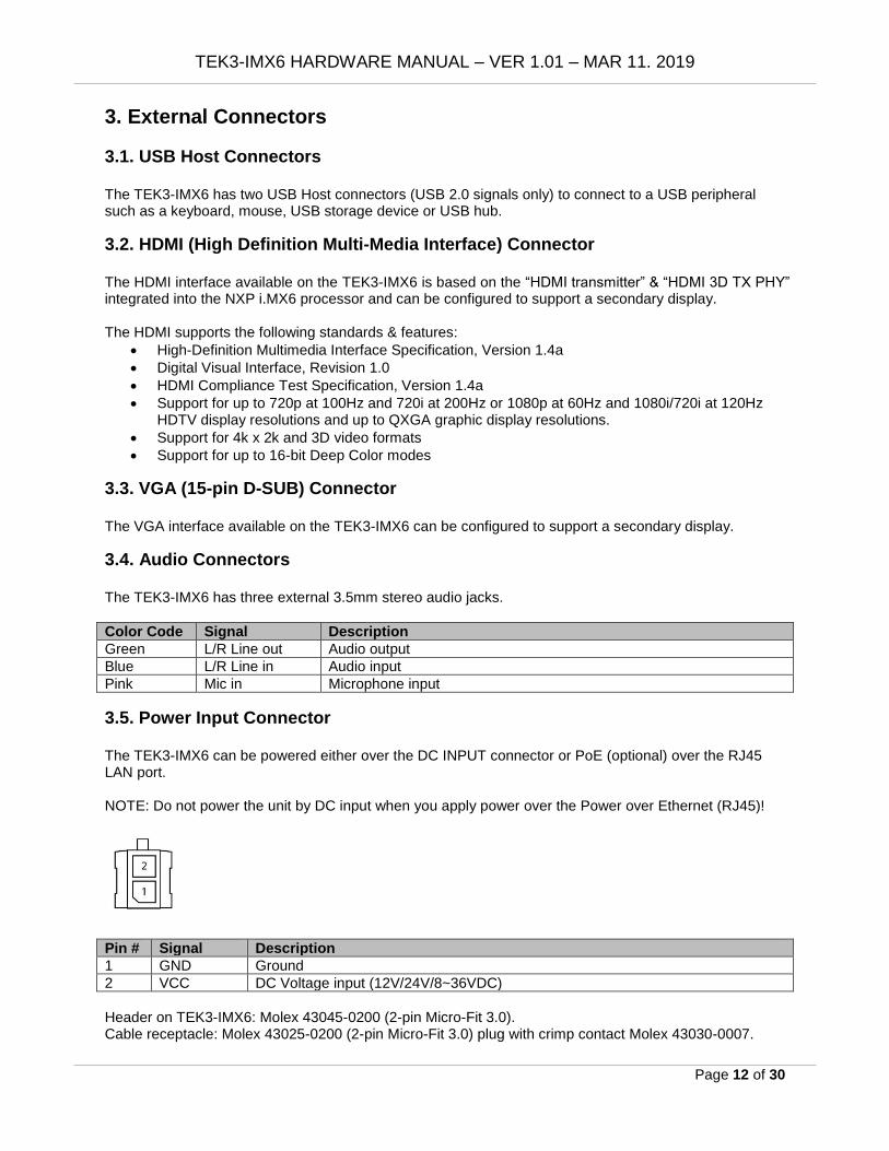
3.5. Power Input Connector The TEK3-IMX6 can be powered either over the DC INPUT connector or PoE (optional) over the RJ45 LAN port. NOTE: Do not power the unit by DC input when you apply power over the Power over Ethernet (RJ45)!
Pin # Signal Description
1 GND Ground
2 VCC DC Voltage input (12V/24V/8~36VDC)
Header on TEK3-IMX6: Molex 43045-0200 (2-pin Micro-Fit 3.0). Cable receptacle: Molex 43025-0200 (2-pin Micro-Fit 3.0) plug with crimp contact Molex 43030-0007.

TEK3-IMX6 HARDWARE MANUAL – VER 1.01 – MAR 11. 2019
Page 13 of 30
3.6. Gigabit Ethernet Interface The TEK3-IMX6 by default comes with a single Gigabit Ethernet RJ45 connector. This connector can support 802.3at Power over Ethernet functionality if configured with the PoE power option (TEK3-IMX6x-Rxx-Exx-LPOE-xxxx-xxxx) by connecting it to an 802.3at compliant PoE switch or power injector.
Pin # 1000 Mbps 100 Mbps 10 Mbps
1 MDI0+ Transmit Data+ Transmit Data+
2 MDI0- Transmit Data- Transmit Data-
3 MDI1+ Receive Data+ Receive Data+
4 MDI2+
5 MDI2-
6 MDI1- Receive Data- Receive Data-
7 MDI3+
8 MDI3-

TEK3-IMX6 HARDWARE MANUAL – VER 1.01 – MAR 11. 2019
Page 14 of 30
3.7. Galvanic Isolated Connectors (TEK3-IMX6x-Rxx-Exx-Lxxx-XG20-xxxx)
(optional) This product is available with four optional connectors: GPIO1, GPIO2, RS-XXX and CAN Bus that can be ordered in either galvanic isolated or non-galvanic isolated versions. The TEK3-IMX6x-Rxx-Exx-Lxxx-XG20-xxxx has four optional galvanic isolated connectors: GPIO1, GPIO2, RS-XXX and CAN Bus. Top view of the galvanic isolated I/0 Expansion module (TXB-I2-GS2-GC2-GG8):
C
B
A
No. Description No. Description
A SW1 DIP switch C SW2 Terminator Resistor DIP switch
B SW3 Terminator Resistor DIP switch
3.7.1. Galvanic Isolated Digital I/O Connectors (GPIO1/GPIO2) (optional) The galvanic isolated GPIO Expansion headers have the following pinout:
GPIO1:
Pin #
Signal Description Voltage Current Max.
GPIO Kernel
GPIO Bank/IO Min. Typ. Max.
1 GPIO1A DIG_IN1 6V 1A 161 6_1
2 GPIO1B DIG_IN2 6V 1A 42 2_10
3 GND_DIO Ground for digital I/O
4 GND Common Ground
5 GPIO1C DIG_OUT5 16V 1.7A 1 1_1
6 GPIO1D DIG_OUT6 16V 1.7A 41 2_9
7 VCC_DIO Supply input for digital I/O 16V
8 VCC Supply output 12V

TEK3-IMX6 HARDWARE MANUAL – VER 1.01 – MAR 11. 2019
Page 15 of 30
GPIO2:
Pin #
Signal Description Voltage Current Max.
GPIO Kernel
GPIO Bank/IO Min. Typ. Max.
1 GPIO2A DIG_IN1 6V 1A 165 6_5
2 GPIO2B DIG_IN2 6V 1A 164 6_4
3 GND_DIO Ground for digital I/O
4 GND Common Ground
5 GPIO2C DIG_OUT5 16V 1.7A 162 6_2
6 GPIO2D DIG_OUT6 16V 1.7A 163 6_3
7 VCC_DIO Supply input for digital I/O 16V
8 VCC Supply output 12V
Header on TEK3-IMX6: Molex 43045-0800 (8-pin Micro-Fit 3.0). Cable receptacle: Molex 43025-0800 (8-pin Micro-Fit 3.0) plug with crimp contact Molex 43030-0007.

TEK3-IMX6 HARDWARE MANUAL – VER 1.01 – MAR 11. 2019
Page 16 of 30
3.7.2. Galvanic Isolated Serial Port (RS-XXX) (optional) The dual 4-wire galvanic isolated serial port can be configured as follows: the primary serial port can only be used as a standard RS-232. The secondary port can be configured either as RS-232, or RS-422 or RS-485. This serial port is set by default as RS-232. Setting the TEK3-IMX6 in other mode will require to open the device and adjust the internal SW1 DIP and SW3 Terminator Resistor DIP switch settings on the TEP I/O Expansion board. The SW1 DIP switch can be found at location “A” and SW3 DIP switch at location “B” in chapter 3.7. Galvanic Isolated Connectors (TEK3-IMX6x-Rxx-Exx-Lxxx-XG20-xxxx) (optional) of this manual. SW1:
Pin # RS-232 (default) RS-422 RS-485
1-8 ON OFF OFF
2-7 OFF ON OFF
3-6 OFF OFF ON
4-5 - - -
SW3:
Pin # ON OFF
1-8 Enable RS-485 Terminator Resistor Disable RS-485 Terminator Resistor
2-7 Enable RS-422 Terminator Resistor Disable RS-422 Terminator Resistor
3-6 - -
4-5 - -
RS-232 + RS-232 (default setup):
Pin # Signal Description Device
1 GND Ground
2 SERIAL1A_TXD Port#1A Transmit data (output) ttymxc0
3 SERIAL1A_RXD Port#1A Receive data (input) ttymxc0
4 SERIAL1A_RTS Port#1A Request-to-send (output) ttymxc0
5 SERIAL1A_CTS Port#1A Clear-to-send (input) ttymxc0
6 GND Ground
7 SERIAL1B_TXD Port#1B Transmit data (output) ttymxc1
8 SERIAL1B_RXD Port#1B Receive data (input) ttymxc1
9 SERIAL1B_RTS Port#1B Request-to-send (output) ttymxc1
10 SERIAL1B_CTS Port#1B Clear-to-send (input) ttymxc1

TEK3-IMX6 HARDWARE MANUAL – VER 1.01 – MAR 11. 2019
Page 17 of 30
RS-232 + RS-422:
Pin # Signal Description Device
1~5 SERIAL1A Identical as above ttymxc0
6 GND Ground
7 SERIAL1B_TXD+ RS-422 Transmit positive data signal (output) ttymxc1
8 SERIAL1B_RXD- RS-422 Receive negative data signal (input) ttymxc1
9 SERIAL1B_RXD+ RS-422 Receive positive data signal (input) ttymxc1
10 SERIAL1B_TXD- RS-422 Transmit negative data signal (output) ttymxc1
RS-232 + RS-485:
Pin # Signal Description Device
1~5 SERIAL1A Identical as above ttymxc0
6 GND Ground
7 SERIAL1B+ RS-485 positive data signal ttymxc1
8 NC
9 NC
10 SERIAL1B- RS-485 negative data signal ttymxc1
NOTE: SERIAL1A port can act by default as serial debug console. Header on TEK3-IMX6: Molex 43045-1000 (10-pin Micro-Fit 3.0). Cable receptacle: Molex 43025-1000 (10-pin Micro-Fit 3.0) plug with crimp contact Molex 43030-0007.
TEK3-IMX6 HARDWARE MANUAL – VER 1.01 – MAR 11. 2019
Page 18 of 30
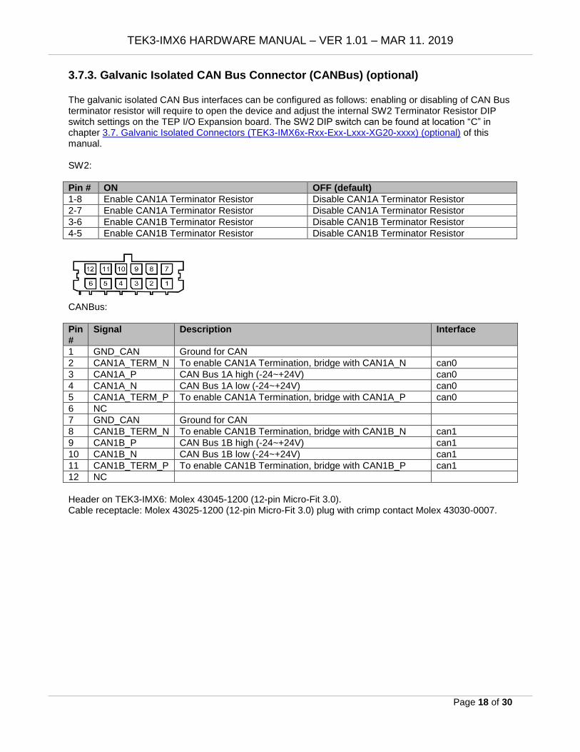
3.7.3. Galvanic Isolated CAN Bus Connector (CANBus) (optional) The galvanic isolated CAN Bus interfaces can be configured as follows: enabling or disabling of CAN Bus terminator resistor will require to open the device and adjust the internal SW2 Terminator Resistor DIP switch settings on the TEP I/O Expansion board. The SW2 DIP switch can be found at location “C” in chapter 3.7. Galvanic Isolated Connectors (TEK3-IMX6x-Rxx-Exx-Lxxx-XG20-xxxx) (optional) of this manual. SW2:
Pin # ON OFF (default)
1-8 Enable CAN1A Terminator Resistor Disable CAN1A Terminator Resistor
2-7 Enable CAN1A Terminator Resistor Disable CAN1A Terminator Resistor
3-6 Enable CAN1B Terminator Resistor Disable CAN1B Terminator Resistor
4-5 Enable CAN1B Terminator Resistor Disable CAN1B Terminator Resistor
CANBus:
Pin #
Signal Description Interface
1 GND_CAN Ground for CAN
2 CAN1A_TERM_N To enable CAN1A Termination, bridge with CAN1A_N can0
3 CAN1A_P CAN Bus 1A high (-24~+24V) can0
4 CAN1A_N CAN Bus 1A low (-24~+24V) can0
5 CAN1A_TERM_P To enable CAN1A Termination, bridge with CAN1A_P can0
6 NC
7 GND_CAN Ground for CAN
8 CAN1B_TERM_N To enable CAN1B Termination, bridge with CAN1B_N can1
9 CAN1B_P CAN Bus 1B high (-24~+24V) can1
10 CAN1B_N CAN Bus 1B low (-24~+24V) can1
11 CAN1B_TERM_P To enable CAN1B Termination, bridge with CAN1B_P can1
12 NC
Header on TEK3-IMX6: Molex 43045-1200 (12-pin Micro-Fit 3.0). Cable receptacle: Molex 43025-1200 (12-pin Micro-Fit 3.0) plug with crimp contact Molex 43030-0007.

TEK3-IMX6 HARDWARE MANUAL – VER 1.01 – MAR 11. 2019
Page 19 of 30
3.8. Non-Galvanic Isolated Connectors (TEK3-IMX6x-Rxx-Exx-Lxxx-XS20-xxxx)
(optional) This product is available with four optional connectors: GPIO1, GPIO2, RS-XXX and CAN Bus that can be ordered in either galvanic isolated or non-galvanic isolated versions. The TEK3-IMX6x-Rxx-Exx-Lxxx-XS20-xxxx has four optional non-galvanic isolated connectors: GPIO1, GPIO2, RS-XXX and CAN Bus. Top view of the non-galvanic isolated I/0 Expansion module (TXB-I2-S2-C2-G8):
A
No. Description No. Description
A SW1 Terminator Resistor DIP switch
3.8.1. Non-Galvanic Isolated Digital I/O Connectors (GPIO1/GPIO2) (optional) The non-galvanic isolated GPIO Expansion headers have the following pinout:
GPIO1:
Pin #
Signal Description Voltage Current Max.
GPIO Kernel
GPIO Bank/IO Min. Typ. Max.
1 GPIO1A DIG_IN1/OUT1 1.65V 3.3V 3.6V 0.33mA 161 6_1
2 GPIO1B DIG_IN2/OUT2 1.65V 3.3V 3.6V 0.33mA 42 2_10
3 NC
4 GND Common Ground
5 GPIO1C DIG_IN5/OUT5 1.65V 3.3V 3.6V 0.33mA 1 1_1
6 GPIO1D DIG_IN5/OUT6 1.65V 3.3V 3.6V 0.33mA 41 2_9
7 NC
8 VCC Supply output 12V
TEK3-IMX6 HARDWARE MANUAL – VER 1.01 – MAR 11. 2019
Page 20 of 30
GPIO2:
Pin #
Signal Description Voltage Current Max.
GPIO Kernel
GPIO Bank/IO Min. Typ. Max.
1 GPIO2A DIG_IN1/OUT1 1.65V 3.3V 3.6V 0.33mA 164 6_5
2 GPIO2B DIG_IN2/OUT2 1.65V 3.3V 3.6V 0.33mA 165 6_4
3 NC
4 GND Common Ground
5 GPIO2C DIG_IN5/OUT5 1.65V 3.3V 3.6V 0.33mA 162 6_2
6 GPIO2D DIG_IN5/OUT6 1.65V 3.3V 3.6V 0.33mA 163 6_3
7 NC
8 VCC Supply output 12V
Header on TEK3-IMX6: Molex 43045-0800 (8-pin Micro-Fit 3.0). Cable receptacle: Molex 43025-0800 (8-pin Micro-Fit 3.0) plug with crimp contact Molex 43030-0007.
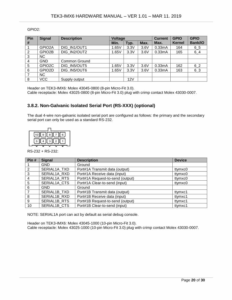
3.8.2. Non-Galvanic Isolated Serial Port (RS-XXX) (optional) The dual 4-wire non-galvanic isolated serial port are configured as follows: the primary and the secondary serial port can only be used as a standard RS-232.
RS-232 + RS-232:
Pin # Signal Description Device
1 GND Ground
2 SERIAL1A_TXD Port#1A Transmit data (output) ttymxc0
3 SERIAL1A_RXD Port#1A Receive data (input) ttymxc0
4 SERIAL1A_RTS Port#1A Request-to-send (output) ttymxc0
5 SERIAL1A_CTS Port#1A Clear-to-send (input) ttymxc0
6 GND Ground
7 SERIAL1B_TXD Port#1B Transmit data (output) ttymxc1
8 SERIAL1B_RXD Port#1B Receive data (input) ttymxc1
9 SERIAL1B_RTS Port#1B Request-to-send (output) ttymxc1
10 SERIAL1B_CTS Port#1B Clear-to-send (input) ttymxc1
NOTE: SERIAL1A port can act by default as serial debug console. Header on TEK3-IMX6: Molex 43045-1000 (10-pin Micro-Fit 3.0). Cable receptacle: Molex 43025-1000 (10-pin Micro-Fit 3.0) plug with crimp contact Molex 43030-0007.
TEK3-IMX6 HARDWARE MANUAL – VER 1.01 – MAR 11. 2019
Page 21 of 30
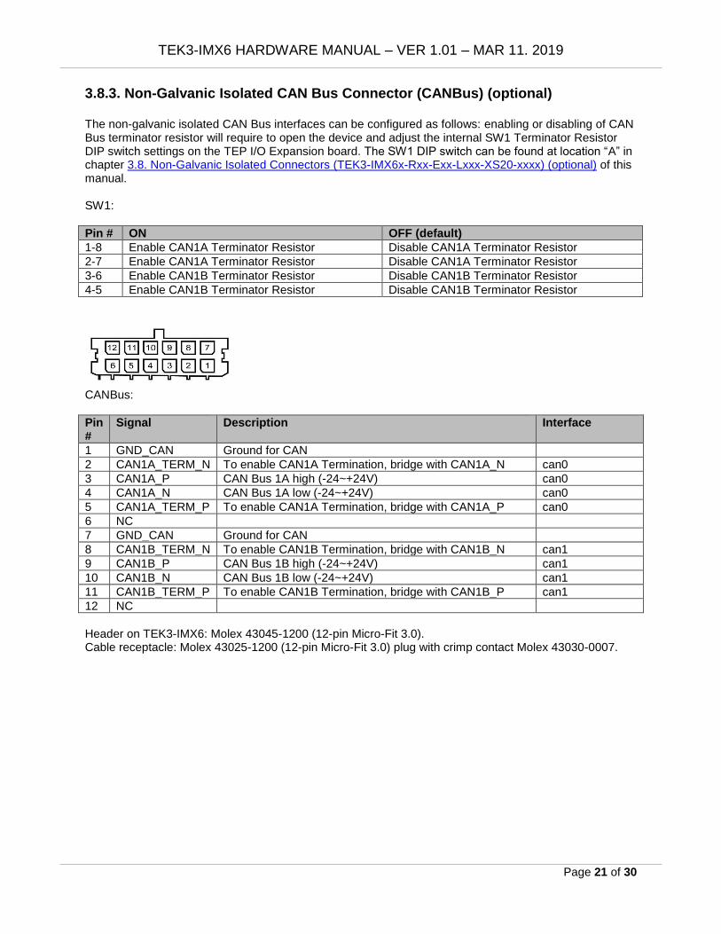
3.8.3. Non-Galvanic Isolated CAN Bus Connector (CANBus) (optional) The non-galvanic isolated CAN Bus interfaces can be configured as follows: enabling or disabling of CAN Bus terminator resistor will require to open the device and adjust the internal SW1 Terminator Resistor DIP switch settings on the TEP I/O Expansion board. The SW1 DIP switch can be found at location “A” in chapter 3.8. Non-Galvanic Isolated Connectors (TEK3-IMX6x-Rxx-Exx-Lxxx-XS20-xxxx) (optional) of this manual. SW1:
Pin # ON OFF (default)
1-8 Enable CAN1A Terminator Resistor Disable CAN1A Terminator Resistor
2-7 Enable CAN1A Terminator Resistor Disable CAN1A Terminator Resistor
3-6 Enable CAN1B Terminator Resistor Disable CAN1B Terminator Resistor
4-5 Enable CAN1B Terminator Resistor Disable CAN1B Terminator Resistor
CANBus:
Pin #
Signal Description Interface
1 GND_CAN Ground for CAN
2 CAN1A_TERM_N To enable CAN1A Termination, bridge with CAN1A_N can0
3 CAN1A_P CAN Bus 1A high (-24~+24V) can0
4 CAN1A_N CAN Bus 1A low (-24~+24V) can0
5 CAN1A_TERM_P To enable CAN1A Termination, bridge with CAN1A_P can0
6 NC
7 GND_CAN Ground for CAN
8 CAN1B_TERM_N To enable CAN1B Termination, bridge with CAN1B_N can1
9 CAN1B_P CAN Bus 1B high (-24~+24V) can1
10 CAN1B_N CAN Bus 1B low (-24~+24V) can1
11 CAN1B_TERM_P To enable CAN1B Termination, bridge with CAN1B_P can1
12 NC
Header on TEK3-IMX6: Molex 43045-1200 (12-pin Micro-Fit 3.0). Cable receptacle: Molex 43025-1200 (12-pin Micro-Fit 3.0) plug with crimp contact Molex 43030-0007.

TEK3-IMX6 HARDWARE MANUAL – VER 1.01 – MAR 11. 2019
Page 22 of 30
3.9. RST Button The TEK3-IMX6 features a “RST” button for system reset.
3.10. S1 Button The TEK3-IMX6 by default boots the unit from internal flash storage (eMMC). By pressing the “S1” button before applying power to the unit and keeping the button pressed for 10 seconds, the unit will boot from an alternative boot media, such as a microSD card. The primary and alternative booth media are determined by internal DIP switch settings. Please see section 4.5. SWITCH1 Boot Mode DIP Switch for more details.
3.11. Micro-SIM Connector The TEK3-IMX6 features an external Micro-SIM cardslot for use by 3G/4G/LTE wireless module. NOTE: This cardslot can be only used by a mini-PCIe 3G/4G/LTE module installed into the MPCIE1 connector. The MPCIE1 connector can be found at location “B” in chapter 4. Internal Connectors and Expansion Options of this manual. No mini-PCIe 3G/4G LTE module is included in this device (must be purchased separately, not sold by TechNexion).
3.12. MicroSD Connector The TEK3-IMX6 features a standard microSD cardslot which is connected to the NXP i.MX6 integrated “Ultra Secured Digital Host Controller” (uSDHC). The following main features are supported by uSDHC:
• Compatible with the MMC System Specification version 4.2/4.3/4.4/4.41/5.0.
• Conforms to the SD Host Controller Standard Specification version 3.0.
• Compatible with the SD Memory Card Specification version 3.0 and supports the “Extended Capacity SD Memory Card”.
• Compatible with the SDIO Card Specification version 3.0.
• Supports 1-bit / 4-bit SD and SDIO modes
The MMC/SD/SDIO host controller can support a single MMC / SD / SDIO card or device.

TEK3-IMX6 HARDWARE MANUAL – VER 1.01 – MAR 11. 2019
Page 23 of 30
3.13. USB OTG (Type-C) Connector The TEK3-IMX6 has one USB Type-C connector (USB 2.0 signals only) that can be used to connect a host computer to the unit for programming and update purposes.
Pin #
Signal Description Pin #
Signal Description
A1 GND Ground B1 GND Ground
A2 NC B2 NC
A3 NC B3 NC
A4 VBUS 5V Universal Serial Bus Power B4 VBUSD 5V Universal Serial Bus Power
A5 CC1 OTG detection signal B5 CC2D OTG detection signal A6 USB_D+ USB differential pair signal
port 1 B6 USB_D+ USB differential pair signal
port 2 A7 USB_D- B7 USB_D-
A8 NC B8 NC
A9 VBUS 5V Universal Serial Bus Power B9 VBUSD 5V Universal Serial Bus Power
A10 NC B10 NC
A11 NC B11 NC
A12 GND Ground B12 GND Ground
3.14. LED Light Indicators The TEK3-IMX6 has four programmable LED Light indicators.
LED # Color GPIO Kernel GPIO Bank/IO
1 Green GPIO 94 3_30
2 Green GPIO 90 3_26
3 Green GPIO 8 1_8
4 Green PWM1 9 1_9
3.15. Antenna Holes There are two antenna holes available (on the rear side). They come fitted with breakaway metal tabs. In order to utilize them, the tabs must be removed by carefully using pincers or pliers.

TEK3-IMX6 HARDWARE MANUAL – VER 1.01 – MAR 11. 2019
Page 24 of 30
4. Internal Connectors and Expansion Options Rear view (opened device) without the I/O Expansion and Power Expansion modules:
B* A* C* F* D* G* E* Internal Connectors and Switches:
No. Description No. Description
A* M.2 KEY-B slot (SATA + USB) E* USB (2 port) header
B* mini-PCIe connector (PCIe + USB) F* I/O Expansion module connector
C* RTC Battery connector G* Power Expansion module connector
D* SWITCH1 Boot mode DIP switch
NOTE: Items marked with * are accessible only after removing the I/O Expansion and Power Expansion
modules.
4.1. M.2 KEY-B Slot The TEK3-IMX6 has an internal M.2 connector (Marked A). TEK3-IMX6Q-Rxx-Exx-Lxxx-xxxx-xxxx supports SATA and USB signals. On the other hand, TEK3-IMX6S-Rxx-Exx-Lxxx-xxxx-xxxx or TEK3-IMX6U-Rxx-Exx-Lxxx-xxxx-xxxx support USB signals only. M.2 cards in the M.2 KEY-B 2242 (22 x 42 mm) form factor are supported.
4.2. Mini-PCIe Connector The TEK3-IMX6 has an internal mini-PCIe connector for full or half size cards (Marked B). It supports PCIe and USB signals. Mini-PCIe Full Size (30 x 50.95 mm) or Half Size (30 x 26.8 mm) cards are supported.
TEK3-IMX6 HARDWARE MANUAL – VER 1.01 – MAR 11. 2019
Page 25 of 30
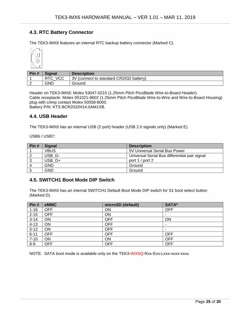
4.3. RTC Battery Connector The TEK3-IMX6 features an internal RTC backup battery connector (Marked C).
Pin # Signal Description
1 RTC_VCC 3V (connect to standard CR2032 battery)
2 GND Ground
Header on TEK3-IMX6: Molex 53047-0210 (1.25mm Pitch PicoBlade Wire-to-Board Header). Cable receptacle: Molex 051021-8602 (1.25mm Pitch PicoBlade Wire-to-Wire and Wire-to-Board Housing) plug with crimp contact Molex 50058-8000. Battery P/N: KTS BCR2032H14.0AM1XB.
4.4. USB Header The TEK3-IMX6 has an internal USB (2 port) header (USB 2.0 signals only) (Marked E). USB6 / USB7:
Pin # Signal Description
1 VBUS 5V Universal Serial Bus Power
2 USB_D- Universal Serial Bus differential pair signal port 1 / port 2 3 USB_D+
4 GND Ground
5 GND Ground
4.5. SWITCH1 Boot Mode DIP Switch The TEK3-IMX6 has an internal SWITCH1 Default Boot Mode DIP switch for S1 boot select button (Marked D).
Pin # eMMC microSD (default) SATA*
1-16 OFF ON OFF
2-15 OFF ON -
3-14 ON OFF ON
4-13 ON OFF -
5-12 ON OFF -
6-11 OFF OFF OFF
7-10 ON ON OFF
8-9 OFF OFF OFF
NOTE: SATA boot mode is available only on the TEK3-IMX6Q-Rxx-Exx-Lxxx-xxxx-xxxx.

TEK3-IMX6 HARDWARE MANUAL – VER 1.01 – MAR 11. 2019
Page 26 of 30
5. Mounting This section describes the mounting procedures for the TEK3-IMX6. The material in area of the mounting must provide sufficient strength for safe mounting of this device.
5.1. Surface Mounting There are 4 mounting holes (M5) on the front side of the device required for surface mounting. Four M4 or M5 screws with at least 8mm head-to-tip length are required to secure this device to the surface. Top view:
1 2
3 4
5.2. DIN Mounting The device can be mounted on a DIN rail by using a DIN-rail bracket. There are four mounting holes (M3) on the rear side of the device required for DIN bracket mounting (30mm DIN rail standard). Secure the DIN bracket to the back of this device by using two M3 screws with at least 5mm head-to-tip length. Bottom view:
1
2 3 4

TEK3-IMX6 HARDWARE MANUAL – VER 1.01 – MAR 11. 2019
Page 27 of 30
6. Ordering Information The TEK3-IMX6 is available in several configurations. Please contact your TechNexion sales contact window or distributor for options and availability details.
6.1. Custom Part Number Rule The TEK3-IMX6 can be ordered in custom tailored configuration to meet special application requirements and conditions according to the following custom part number creation rules. Custom part numbers carry minimum order quantities (MOQ). Please connect with your TechNexion distributor or account manager for conditions and availability. Part number format: TEK3-IMX6x-Rxx-Exx-Lxxx-xxxx-xxxx-xxxx
Interface Code Description
Processor IMX6S NXP i.MX6Solo
IMX6U NXP i.MX6DualLite
IMX6Q NXP i.MX6Quad
Memory R05 512MB DDR3
R10 1GB DDR3
R20 2GB DDR3
R40 4GB DDR3
Storage E04 eMMC 4GB
E08 eMMC 8GB
EXX eMMC other capacity
Power Expansion L112 TXR-P1-12V-LAN1 (12V 3A)
L130 TXR-P1-1030V-LAN1 (8-36V 5A)
LPOE TXR-P1-12V-POE1 (12V 3A) or (PoE 802.3at)
I/O Expansion - -
XS20 2x RS-232 + 2x CAN + 8x GPIO
XG20 2x RS-232 + 2x CAN + 8x GPIO (Galvanic Isolated)
Wi-Fi / Bluetooth - -
9377 Qualcomm QCA9377 802.11a/b/g/n/ac (2.4 + 5GHz) + Bluetooth 5
Custom ID XXXX Custom Part number ID for customized software loader and special component (BOM)

TEK3-IMX6 HARDWARE MANUAL – VER 1.01 – MAR 11. 2019
Page 28 of 30
6.2. Standard Package Contents
Item Partnumber Description
1 TEK3-IMX6 Fanless box PC computing system with NXP i.MX6
2 Accessoires 1x plastic washer (for M.2 card)
1x screw (M3) (for M.2 card)
1x mini-PCIe screw (M2)
1x hexagonal bolt
1x rubber feet pad set
1x DC power latch cable (2-pin Micro-Fit 3.0)
NOTE: Pack contents might vary depending on your ordered configuration.

TEK3-IMX6 HARDWARE MANUAL – VER 1.01 – MAR 11. 2019
Page 29 of 30
7. Important Notice TechNexion reserve the right to make corrections, modifications, enhancements, improvements, and other changes to its products and services at any time and to discontinue any product or service without notice. Customers should obtain the latest relevant information before placing orders and should verify that such information is current and complete. All products are sold subject to TechNexion terms and conditions of sale supplied at the time of order acknowledgment. TechNexion warrants performance of its hardware products to the specifications applicable at the time of sale in accordance with TechNexion standard warranty. Testing and other quality control techniques are used to the extent TechNexion deems necessary to support this warranty. Except where mandated by government requirements, testing of all parameters of each product is not necessarily performed. TechNexion assumes no liability for applications assistance or customer product design. Customers are responsible for their products and applications using TechNexion components. To minimize the risks associated with customer products and applications, customers should provide adequate design and operating safeguards. TechNexion does not warrant or represent that any license, either express or implied, is granted under any TechNexion patent right, copyright, mask work right, or other TechNexion intellectual property right relating to any combination, machine, or process in which TechNexion products or services are used. Information published by TechNexion regarding third-party products or services does not constitute a license from TechNexion to use such products or services or a warranty or endorsement thereof. Use of such information may require a license from a third party under the patents or other intellectual property of the third party, or a license from TechNexion under the patents or other intellectual property of TechNexion. TechNexion products are not authorized for use in safety-critical applications (such as life support) where a failure of the TechNexion product would reasonably be expected to cause severe personal injury or death, unless officers of the parties have executed an agreement specifically governing such use. Buyers represent that they have all necessary expertise in the safety and regulatory ramifications of their applications and acknowledge and agree that they are solely responsible for all legal, regulatory and safety-related requirements concerning their products and any use of TechNexion products in such safety-critical applications, notwithstanding any applications-related information or support that may be provided by TechNexion. Further, Buyers must fully indemnify TechNexion and its representatives against any damages arising out of the use of TechNexion products in such safety-critical applications. TechNexion products are neither designed nor intended for use in military/aerospace applications or environments unless the TechNexion products are specifically designated by TechNexion as military grade or "enhanced plastic." Only products designated by TechNexion as military-grade meet military specifications. Buyers acknowledge and agree that any such use of TechNexion products which TechNexion has not designated as military-grade is solely at the Buyer's risk, and that they are solely responsible for compliance with all legal and regulatory requirements in connection with such use. TechNexion products are neither designed nor intended for use in automotive applications or environments unless the specific TechNexion products are designated by TechNexion as compliant with ISO/TS 16949 requirements. Buyers acknowledge and agree that, if they use any non-designated products in automotive applications, TechNexion will not be responsible for any failure to meet such requirements.

TEK3-IMX6 HARDWARE MANUAL – VER 1.01 – MAR 11. 2019
Page 30 of 30
8. Disclaimer © 2001-2019 TechNexion Ltd. All Rights Reserved. No part of this document may be photocopied, reproduced, stored in a retrieval system, or transmitted, in any form or by any means whether, electronic, mechanical, or otherwise without the prior written permission of TechNexion Ltd. No warranty of accuracy is given concerning the contents of the information contained in this publication. To the extent permitted by law no liability (including liability to any person by reason of negligence) will be accepted by TechNexion Ltd., its subsidiaries or employees for any direct or indirect loss or damage caused by omissions from or inaccuracies in this document. TechNexion Ltd. reserves the right to change details in this publication without notice. Product and company names herein may be the trademarks of their respective owners. TechNexion Ltd. 16F-5, No. 736, Zhongzheng Road, ZhongHe District, 23511, New Taipei City, Taiwan Phone : +886-2-82273585 Fax : +886-2-82273590 E-mail : [email protected] Web : https://www.technexion.com/