tekla structures 2019i release notes · 2019-10-02 · tekla structures 2019i, you cannot open it...
TRANSCRIPT

Tekla Structures 2019iUpgrade to this version
September 2019
©2019 Trimble Solutions Corporation

Contents
1 Tekla Structures 2019i release notes...........................................51.1 Trimble Connect Visualizer - Create 3D renderings of your models........... 61.2 Switch between manual and automatic applying in the property
pane.................................................................................................................... 9Enable manual applying of properties.................................................................................. 9Enable automatic applying of properties........................................................................... 10The PropertyPaneSettings.xml file...................................................................................... 10
1.3 Updates to the property pane, UDAs, and to the Property pane editor.. 11New options to control the visibility of properties and user-defined attributesin the property pane............................................................................................................. 11Updates in the Property pane editor.................................................................................. 13Improved search in the property pane............................................................................... 15Improvements in copying of properties..............................................................................15
1.4 Snapping improvements................................................................................ 15Orthogonal snapping has lower priority among the snap points than previously........15Snap tooltips for snap points............................................................................................... 16Snapping color changes........................................................................................................17Setting the temporary reference point by using a right-click command........................ 22
1.5 Search in model............................................................................................... 221.6 New part types: lofted plate and lofted slab............................................... 22
Prerequisites and examples of lofted plates and lofted slabs......................................... 22Create a lofted plate or a lofted slab...................................................................................24Correct the geometry of a lofted plate or split a lofted plate.......................................... 29Limitations.............................................................................................................................. 29New template attribute IS_LOFTED_PART...........................................................................29
1.7 Weld clash check, pour management, and other modelingimprovements................................................................................................. 29Detect clashes between welds and other objects............................................................. 30Numbering improvements................................................................................................... 30Performance improvements in pour management.......................................................... 30New ways to create item shapes and edit model geometry............................................ 31
1.8 View improvements........................................................................................ 31Show model views in a selected view angle....................................................................... 31Show assemblies and components in a selected view angle...........................................32
1.9 Improvements in rebar sets and Rebar shape manager............................32Create cranking using end detail modifiers........................................................................33Group rebar set bars manually using property modifiers................................................34Other modifier improvements............................................................................................. 34Face-specific concrete covers for rebar sets...................................................................... 35Show or hide rebar set guidelines and modifiers..............................................................35Keyboard shortcuts for reinforcement selection switches...............................................36Improvements in leg faces....................................................................................................36New .inp file for rebar set user-defined attributes............................................................36
2

Improvements in Rebar shape manager............................................................................ 371.10 Improvements in drawings............................................................................ 37
Improvements in drawing views.......................................................................................... 38Improvements in reinforcement drawing properties........................................................40Improvements in reinforcement group marks.................................................................. 41Improvements in dimensioning...........................................................................................44Improvements in dimension tags........................................................................................ 44Improvements in Document manager................................................................................45
1.11 Improvements in rebar drawing tools..........................................................46Rebar group marking............................................................................................................ 47Rebar pull-out picture and marking.................................................................................... 48Rebar group dimensioning...................................................................................................48
1.12 Printing to multiple printers and other printing improvements.............. 48Print drawings to multiple printers in one go.................................................................... 48Other printing improvements.............................................................................................. 52
1.13 Improvements in Tekla Model Sharing......................................................... 52Reasons of write out failures are stored in log files.......................................................... 52Improved pour management...............................................................................................53Improved and more robust sharing operations................................................................ 53
1.14 Changes in Tekla Structures installation......................................................531.15 New structure of firm and project folders................................................... 531.16 Interoperability improvements.....................................................................54
Reference models..................................................................................................................55IFC object conversion............................................................................................................ 56IFC export................................................................................................................................56Point clouds............................................................................................................................57
1.17 Export to 3D DGN v8 - New 3D DGN export..................................................57Create object group color representations ....................................................................... 58Create base points ................................................................................................................58Export to 3D DGN v8............................................................................................................. 58
1.18 Export to 3D DWG - New 3D DWG export......................................................59Create object group color representations ....................................................................... 60Create base points ................................................................................................................60Export to 3D DWG..................................................................................................................60
1.19 Updates in tools for concrete fabrication.................................................... 61Export Unitechnik (79)...........................................................................................................61Export EliPlan file................................................................................................................... 62BVBS Export............................................................................................................................63
1.20 Improvements in components...................................................................... 64Concrete components...........................................................................................................64Steel components..................................................................................................................69
1.21 Changes in advanced options........................................................................ 73New advanced options..........................................................................................................73
2 Tekla Structures 2019i administrator's release notes.............742.1 Administrator's release notes: General settings.........................................74
Administrator's release notes: Model templates in version update ............................. 75 Administrator's release notes: Applications & components catalog maintenance .....78Administrator's release notes: New structure of firm and project folders.....................80Administrator's release notes: Lofted plate and lofted slab............................................ 81
3

Administrator's release notes: UDA handling in the property pane............................... 83Localization tasks............................................................................................................. 86
Administrator's release notes: Multiple printing settings.................................................94Administrator's release notes: Improvements in drawings..............................................94
Cast unit drawing creation.............................................................................................. 94Improvements in rebar drawing tools........................................................................... 95
Administrator's release notes: Improvements in marks...................................................96Merge marks..................................................................................................................... 96Perpendicular leader line / Leader line to first and last.............................................. 98
Administrator's release notes: Interoperability improvements.......................................99Export to 3D DWG settings..............................................................................................99Export to 3D DGN settings............................................................................................ 100
2.2 Administrator's release notes: Steel settings............................................101Administrator's release notes: Steel components...........................................................101
2.3 Administrator's release notes: Concrete settings.....................................102Administrator's release notes: Rebar sets and other reinforcement improvements. 102
Cranking using end detail modifiers............................................................................ 102Face-specific concrete covers....................................................................................... 102Manual grouping............................................................................................................ 103Moving all rebar set related UDAs to one .inp file......................................................104Rebar shape manager................................................................................................... 104
Administrator's release notes: Updates in tools for concrete fabrication...................104Administrator's release notes: Concrete components................................................... 104
3 Localization release notes........................................................106
4 Upgrade Tekla Structures to a new version........................... 1074.1 Update the Tekla license server.................................................................. 1084.2 Renew a Tekla license................................................................................... 1094.3 Copy personal settings to a new Tekla Structures version...................... 1114.4 Transfer customized information to a new Tekla Structures version.... 111
5 Tekla Structures service packs.................................................1135.1 Install a Tekla Structures service pack....................................................... 1135.2 Install an earlier Tekla Structures service pack........................................ 115
6 Disclaimer...................................................................................116
4

1 Tekla Structures 2019i releasenotes
Welcome to Tekla Structures 2019i!
Check the links below for information on the many new features andimprovements in this version:
• Trimble Connect Visualizer - Create 3D renderings of your models(page 6)
• Switch between manual and automatic applying in the property pane(page 9)
• Updates to the property pane, UDAs, and to the Property pane editor(page 11)
• Snapping improvements (page 15)
• Search in model (page 22)
• New part types: lofted plate and lofted slab (page 22)
• Weld clash check, pour management, and other modeling improvements(page 29)
• View improvements (page 31)
• Improvements in rebar sets and Rebar shape manager (page 32)
• Improvements in drawings (page 37)
• Improvements in rebar drawing tools (page 46)
• Printing to multiple printers and other printing improvements (page 48)
• Improvements in Tekla Model Sharing (page 52)
• Changes in Tekla Structures installation (page 53)
• New structure of firm and project folders (page 53)
• Interoperability improvements (page 54)
• Export to 3D DGN v8 - New 3D DGN export (page 57)
Tekla Structures 2019i release notes 5

• Export to 3D DWG - New 3D DWG export (page 59)
• Updates in tools for concrete fabrication (page 61)
• Improvements in components (page 64)
• Changes in advanced options (page 73)
• Tekla Structures 2019i fix list
Compatibility
We suggest that you complete any unfinished models using your currentversion of Tekla Structures.
This version is not backwards compatible. When you create or save a model inTekla Structures 2019i, you cannot open it in older versions due to databasedifferences.
Tekla Structures 2019i can only be installed on 64-bit Windows operatingsystems.
See the Tekla Structures 2019i Hardware Recommendations for moreinformation.
Tekla Structures 2019i requires Tekla License Server 2017 or later. To checkwhich license server version to use with your current Tekla Structures version,see Which license server version to use.
Administrator's release notes
Advanced users should read the Tekla Structures administrator's release notes(page 74) for information on how to apply the additional customizationsavailable in this release.
Localization release notes
Environment-specific changes are explained in the Localization release notes(page 106).
Tekla Open API release notes
The Tekla Open API release notes can be found in the Tekla Developer Center .
1.1 Trimble Connect Visualizer - Create 3D renderings ofyour modelsStarting from Tekla Structures 2019i, you can now access Trimble ConnectVisualizer directly from Tekla Structures. In Trimble Connect Visualizer, you cantake snapshots or create animations that demonstrate the design of yourmodels and the build options, and use the snapshots and animations to createmore appealing sales and project presentations.
Tekla Structures 2019i release notes 6 Trimble Connect Visualizer - Create 3D renderingsof your models

Create 3D renderings and set material type mappings
The Visualize commands are located on the View tab.
• Click Visualize selected to open a rendering of the selected model objectsin Trimble Connect Visualizer.
• Click Visualize all to open a rendering of the entire model in TrimbleConnect Visualizer.
• Click Visualizer material type settings to open the Visualizer settingsdialog box, where you can adjust how the materials in your model areshown in Trimble Connect Visualizer.
The material type mappings can be saved either:
• to the \attributes folder under the model folder, so that all users ofthe model can use the material type mappings.
• to the app data, so that the same material type mappings can beapplied to all of your models.
Adjust the model view in Trimble Connect Visualizer
Tekla Structures 2019i release notes 7 Trimble Connect Visualizer - Create 3D renderingsof your models

You can zoom, pan, and rotate the model to view different angles of themodel.
To Do thisZoom in or out Do either of the following:
• Scroll forward or backward with the mousewheel.
• Press the W and S keys on the keyboard.Pan the model Do either of the following:
• Hold down the left mouse button, and drag themodel as needed.
• Press the A and D keys on the keyboard.Rotate the model 1. Place the mouse pointer over the point around
which you want to rotate the model.
2. Hold down the left mouse button.
3. Drag the model as needed.
Click on the Trimble Connect Visualizer side pane to further adjust thescene. You can change:
• The used skybox, or background, and its rotation
• The position of the sun
• The brightness of the scene
• The visibility and position of the ground plane
Take and view snapshots
All snapshots that you take in Trimble Connect Visualizer are saved in the C:\Users\<username>\Pictures\TrimbleConnectVisualizer folder.
• To take a snapshot of the current view, click in the Trimble ConnectVisualizer side pane.
• To open the C:\Users\<username>\Pictures\TrimbleConnectVisualizer folder and see all snapshots that you have
taken, click .
Create animations
You can create animations that show the model from different angles, orviews.
To start creating animations, click on the Trimble Connect Visualizer sidepane.
Tekla Structures 2019i release notes 8 Trimble Connect Visualizer - Create 3D renderingsof your models

Then, click + to add the views that you want to include in the animation.
You can also adjust the speed of the animation and the sun position, andpreview the animation.
1.2 Switch between manual and automatic applying inthe property paneIn Tekla Structures 2019i, when you modify properties in the property pane,you can use the new Set default values automatically option to switchbetween automatic and manual applying of properties for the next objects ofthe same type.
Previously, Tekla Structures always automatically saved the modifiedproperties and applied them for the next objects of the same type. The Setdefault values automatically option makes the property pane moreconsistent with the dialog boxes, where you use the Apply button to set theproperties for next objects of the same type. Now you can follow the sameworkflow both in the property pane and in the dialog boxes.
The Set default values automatically option is not dependent on theselected object type. You can switch between manual and automatic applyingat any time.
Enable manual applying of properties1. Select an object in the model.
2. Click the Property pane settings button in the property pane toopen a drop-down menu.
3. Ensure that the Set default values automatically option is not selected.
A Set as default button appears at the bottom of the property pane.
Note that if you have selected multiple objects in the model, the Set asdefault button does not appear.
4. Change the property values as needed.
5. Select how to proceed.
Tekla Structures 2019i release notes 9 Switch between manual and automatic applyingin the property pane

• To modify only the selected object, click Modify.
• To modify the selected object and to use the current values for thenext objects of the same type, click the Set as default button and thenclick Modify.
• To use the current values for the next objects of the same type, but notto modify the selected object, click the Set as default button.
Depending on your actions, Tekla Structures either modifies the selectedobject or creates the next object of the same type using the current values.
Enable automatic applying of propertiesThis is the default option.
1. Select an object in the model.
2. Click the Property pane settings button in the property pane toopen a drop-down menu.
3. Ensure that the Set default values automatically option is selected.
When the Set default values automatically option is selected, TeklaStructures automatically uses the current values for the next objects ofthe same type.
4. Change the property values as needed.
5. Click Modify.
Tekla Structures modifies the object and creates the next object of the sametype using the current values.
The PropertyPaneSettings.xml fileWhen you modify the property pane settings, the current settings are saved tothe PropertyPaneSettings.xml file in the ..\Users\<user>\AppData\Local\Trimble\Tekla Structures\<version>\UI\PropertyPane\folder. If you do not change the settings, the PropertyPaneSettings.xmlfile is not created.
The settings in the PropertyPaneSettings.xml file are:
• FilterMode: ByData for Show properties that have a value in theproperty pane settings
• FilterMode: ByGroup for Show properties based on visibility settingsin the property pane settings
• AutoApply: True when Set default values automatically in the propertypane settings is selected
Tekla Structures 2019i release notes 10 Switch between manual and automatic applyingin the property pane

• AutoApply: False when Set default values automatically in theproperty pane settings is not selected
The PropertyPaneSettings.xml file is read when Tekla Structures is startedand a model is opened.
If the settings in the PropertyPaneSettings.xml file are customized, thecompany administrators can distribute the customized property pane settingsto other users in the company. The PropertyPaneSettings.xml file needsto be placed in the \PropertyPane\ subfolder in a model, project(XS_PROJECT), firm (XS_FIRM) or environment (XS_SYSTEM) folder. Theproperty pane settings in the ..\Users\<user>\AppData\Local\Trimble\Tekla Structures\<version>\UI\PropertyPane\ folder has thehighest priority, and after that Tekla Structures uses the default search order.
If the PropertyPaneSettings.xml file is placed in several different folderlocations, Tekla Structures reads the settings from different folders andmerges them.
1.3 Updates to the property pane, UDAs, and to theProperty pane editorTekla Structures 2019i introduces improvements in the property pane and theProperty pane editor. With these updates, especially the viewing andmodifying of user-defined attributes (UDAs) is now easier and morestraightforward.
New options to control the visibility of properties and user-defined attributes in the property paneYou can now control which properties are shown in the property pane withoutcustomizing the property pane layout.
Click the Visibility button to open a drop-down menu in the property pane.When you open the property pane for the first time without anycustomizations in firm, project, or environment folders, the Show propertiesbased on visibility settings option is selected by default.
Tekla Structures 2019i release notes 11 Updates to the property pane, UDAs, and to theProperty pane editor

Expand all or Collapse all
Use to expand or collapse all the property groups.
Show properties that have a value
Select to show only those properties that have a value. This is useful especiallywith user-defined attributes (UDAs). UDAs that have a value are always shown,even if they have not been added to the property pane layout. This means thatyou can view and modify the UDA values in the property pane withoutcustomizing the property pane layout.
1. Select objects in the model.
Property pane shows all the properties and UDAs for which you orsomeone else has entered a value. Properties and UDAs which do nothave a value are hidden.
UDAs that are not included in your current property pane layout butwhich have a value are listed in the Additional matches property group.
2. Modify the property values as needed.
3. If you want to enter a value to an empty property, use the search totemporarily show the needed properties, or select the Show propertiesbased on visibility settings option.
The Show properties that have a value option is common for all objecttypes. For example, if you select a steel beam in the model and use the Showproperties that have a value option, and then select a concrete beam in the
Tekla Structures 2019i release notes 12 Updates to the property pane, UDAs, and to theProperty pane editor

model, only those properties that have a value are shown for the concretebeam as well.
Show properties based on visibility settings
Select which property groups are visible and which are hidden. You can showand hide property groups by clicking the property group names. The eyesymbols indicate which property groups are visible and which are hidden. Youcan show and hide only the main level property groups, not nested groups.
1. Select objects in the model.
Property pane shows all the property groups which are visible in theproperty pane.
Property groups with the icon are visible. Property groups with the icon are hidden.
2. Modify the property values as needed.
3. If you want to make a hidden property group visible, click the eye iconagain.
The Show properties based on visibility settings option is common for allobject types. If different object types have property groups of the same name,the visibility of a property group is adjusted for all the object types. Forexample, if you select a steel beam and hide the Position property group, andthen select a concrete beam, the Position property group is hidden for theconcrete beam as well.
To easily define the default visibility of property groups, use the Propertypane editor. Note that the changes in the visibility settings in the propertypane override the default settings defined in the Property pane editor.
Customize...
Use to open the Property pane editor and customize the property panelayout
Updates in the Property pane editor
Set property groups hidden or visible
You can define whether the property groups in the property pane are visible orhidden by default.
For example, if you are an administrator, you can create property groups fordifferent user-defined attributes (UDAs) in the Property pane editor, andthen set the default visibility for each of the property groups.
1. In the property pane layout on the right, select the property groups youwant to hide.
Tekla Structures 2019i release notes 13 Updates to the property pane, UDAs, and to theProperty pane editor

2. Right-click and select Hide by default.
The eye symbol changes to hidden: . The selected property groups arenow by default hidden in the property pane.
3. To have the property groups again by default visible in the property pane,right-click and select Show by default.
The eye symbol changes to visible: . The selected property groups arenow by default visible in the property pane.
Note that visibility changes in the property pane override the default settingsdefined in the Property pane editor.
Copy multiple property groups
In the Property pane editor, you can now select multiple property groups tobe copied.
1. In the property pane layout on the right, select the property groups to becopied.
2. Right-click and select Copy properties, or click .
The copied property groups and the nested groups inside the propertygroups are shown in the middle column. The copied property groups areexpanded and the content of the groups is shown.
3. Add the copied properties to a property pane layout by dragging theCopied properties box from the middle column to the property panelayout on the right.
All the copied property groups are added to the property pane layout asthey are. Previously, the copied properties were nested inside a Copiedproperties container.
Additionally, when you add copied properties to the property pane layout andthe property group would be empty as a result of duplicate or incompatibleproperties, the group is not created at all. Previously, an empty Copiedproperties container was created without any properties.
Tekla Structures 2019i release notes 14 Updates to the property pane, UDAs, and to theProperty pane editor

Improved search in the property paneSearch in the property pane has been improved. Now the search finds all theproperties and user-define attributes (UDAs) that are available for the objecttype.
If you have several object types selected in the model, the search findsproperties that are common to all the selected object types. UDAs that matchto the search criteria are shown even if they have not been added to theproperty pane layout. This means that you can view and modify the UDAvalues in the property pane without customizing the property pane layout.
Properties and UDAs that are not included in your current property panelayout are listed in the Additional matches property group.
Note that the search results may vary depending on the environment you areusing. Different environments can have different sets of properties available.
Additionally, if you enter a single asterisk * in the search box, all propertiesand UDAs available for the selected object type are shown. You can then easilyenter a value for a property or for an UDA, even if the property or the UDA isnot visible in the property pane by default.
Improvements in copying of propertiesYou can now press Enter to finish the copying of properties instead of clickingthe Modify button.
1.4 Snapping improvementsTekla Structures 2019i introduces new colors and other visual cues forsnapping. Also, the behavior of the orthogonal snapping has been slightlychanged.
Orthogonal snapping has lower priority among the snappoints than previouslyThe behavior of the Ortho tool has been changed. Now the orthogonal snappoints have the lowest priority among the snap points. If Tekla Structuresdetects any other possible snap point than an orthogonal point, TeklaStructures uses the found snap point instead of the orthogonal snap point. If
Tekla Structures 2019i release notes 15 Snapping improvements

there are no other possible snap points found, then Tekla Structures uses theorthogonal snap point.
Snap tooltips for snap pointsNow when you start a command that requires picking points and you movethe mouse pointer over objects in the model, Tekla Structures displays a snaptooltip that shows the name of the snap point.
For example:
To show or hide these snap tooltips, click File --> Settings and select the Snaptooltips check box.
Tekla Structures 2019i release notes 16 Snapping improvements

Snapping color changesThe colors related to snapping have been enhanced to make the snappingeasier and more accurate. The different visual cues in the model help you topick correct positions when you create model objects.
• When the Ortho tool is active and you start a command that requiressnapping to two or more points, for example a beam or polybeam, TeklaStructures displays a rubber band line between the last point picked andthe snap point. The color of the cursor, line, and the angle symbol followsthe color of the work plane axis: red for x-axis, green for y-axis and blue for
Tekla Structures 2019i release notes 17 Snapping improvements

z-axis. For any other direction the line between the last point picked andthe snap point and the cursor is gray.
• If you are using the DirectX rendering:
when you start a command that requires snapping to several points, forexample a polybeam or a slab, Tekla Structures now displays the linesbetween picked points as light gray and dimension lines as black.
Tekla Structures 2019i release notes 18 Snapping improvements

If you are using the OpelGL rendering:
the lines between picked points are white and the dimension lines areblack.
• If you are using the DirectX rendering:
the rubber band line between the last point picked and the snap point nowhas a new line type and color which is clearly visible regardless of the
Tekla Structures 2019i release notes 19 Snapping improvements

background color of the model. The color of the rubber band line and thecolor of the reference point symbol, which is the last picked point, is nowlight gray.
If you are using the OpenGL rendering:
the color of the rubber band line and the color of the reference pointsymbol, which is the last picked point, is now white.
Tekla Structures 2019i release notes 20 Snapping improvements

• Tekla Structures now displays a turquoise reference line or geometry line ofthe object showing the line or the edge to which the snap point belongs to.
Tekla Structures 2019i release notes 21 Snapping improvements

Setting the temporary reference point by using a right-clickcommandIn Tekla Structures 2019, the handling of temporary reference pointinformation was changed. Starting from Tekla Structures 2019, the referencepoint information is cleared when you interrupt a command. If you wanted touse the reference points in Tekla Structures 2019, you had to set the referencepoint manually by pressing the Ctrl key and picking a point when you run acommand.
Now in Tekla Structures 2019i, you can set the temporary reference point alsoby right-clicking when a command is running and selecting the Definetemporary snap reference point option. If you use the Define temporarysnap reference point command, you need to activate it for every referencepoint you pick.
1.5 Search in modelNow you can quickly search for objects in the entire model or within theselected model objects by using the Model search toolbar.
When you run a search in the model, Tekla Structures searches for objectswhose property values contain the search term, and then highlights andselects the objects that have matching property values.
For more information, see Search for model objects.
1.6 New part types: lofted plate and lofted slabTekla Structures 2019i introduces new part types: steel lofted plate andconcrete lofted slab. Use lofted plates to model rolled plates and plates withdouble-curved form, for example. Use lofted slabs to model curved anddouble-curved slabs or walls, for example.
Prerequisites and examples of lofted plates and lofted slabsBefore you can create lofted plates or lofted slabs, you need to haveconstruction objects in your model. Tekla Structures creates the shape of thelofted part according to the geometry of the used construction objects.
You can connect the following construction objects as a lofted plate or a loftedslab:
Tekla Structures 2019i release notes 22 Search in model

• construction line to construction line
For example:
• construction line to construction arc
For example:
• construction arc to construction arc
For example:
Tekla Structures 2019i release notes 23 New part types: lofted plate and lofted slab

• construction circle to construction circle
For example:
Create a lofted plate or a lofted slab1. Create the needed construction objects in the model. The shape of the
lofted part is based on the construction object shape.
You need to have
• construction lines
• construction arcs
OR
• construction circles
2. Depending on whether you are creating a lofted plate or a lofted slab:
• On the Steel tab, click Plate --> Create lofted plate .
Tekla Structures 2019i release notes 24 New part types: lofted plate and lofted slab

• On the Concrete tab, click Slab Create lofted slab
3. On the toolbar that appears , click a button to specify whether tocreate the part by using two construction objects, or by using aconstruction object and a point.
• If you selected Using two construction objects :
a. Select the first construction object: line, arc, or circle.
For example, if you are using two construction circles to create alofted plate:
Tekla Structures 2019i release notes 25 New part types: lofted plate and lofted slab

b. Select the second construction object:
Tekla Structures creates the lofted plate between the selectedconstruction objects.
• If you selected Using one construction object and a point :
a. Select the first construction object: line, arc or circle.
For example:
Tekla Structures 2019i release notes 26 New part types: lofted plate and lofted slab

Tekla Structures shows a preview of the part geometry. Use thepreview to set the direction and the height of the lofted part.
b. Pick a point.
Tekla Structures creates the lofted slab based on the preview.
Tekla Structures 2019i release notes 27 New part types: lofted plate and lofted slab

4. If you want to modify the shape of the lofted part, use the directmodification dimension handles and dimension values.
For example:
Tekla Structures 2019i release notes 28 New part types: lofted plate and lofted slab

Correct the geometry of a lofted plate or split a lofted plate• In some cases when you try to create a lofted plate or a lofted slab by using
construction lines, arcs, or circles, the geometry of the part would becomeself-intersecting. In these situations the part is not created, and TeklaStructures displays the following status bar message: The resultingsurface would be self intersecting.
With construction lines or arcs you can try to resolve the situation bychanging the modeling direction of the construction lines or arcs. Select the
construction line or arc, and on the contextual toolbar click Swap ends.
With construction circles you can try to resolve the situation by movingeither of the circles.
• If needed, you can split lofted parts. You cannot split closed cylindrical orconical lofted parts.
Use the Split command on the Edit tab.
Limitations• You can create unfolded single-part drawings of non-closed cylindrical and
conical lofted plates, meaning that the lofted plate was created by usingconstruction arcs but not construction circles. Other types of lofted platescannot be unfolded.
• Rebar sets do not work with lofted parts.
New template attribute IS_LOFTED_PARTUse the IS_LOFTED_PART template attribute in filtering, fox example, to checkwhether the part is a lofted part. The attribute returns 1 if the object is a loftedpart, otherwise it returns 0.
1.7 Weld clash check, pour management, and othermodeling improvementsTekla Structures 2019i contains the following new features and improvementsin modeling:
Tekla Structures 2019i release notes 29 Weld clash check, pour management, and othermodeling improvements

Detect clashes between welds and other objectsWhen you run a clash check using Tekla Structures 2019i, you can check themodel for duplicate and overlapping welds and for clashes that occur betweenwelds and other objects such as parts and bolts.
To do this:
1. Click File menu --> Settings --> Options to open the Options dialog box.
2. Go to the Clash check settings.
3. In the Exact solid weld clash check list, select Yes.
4. Modify the other clash check settings if needed.
5. Run the clash check.
Tekla Structures checks the welds against other welds, against bolts, andagainst the real geometry of the part profiles including roundings, and usingthe weld solid dimensions with normal accuracy.
When you review the clash check results, note that you can now show a newcolumn, Object Type, in the Clash Check Manager dialog box.
Numbering improvementsNow if a part has a single-part drawing and you modify the part so that itbecomes identical to another part, the following things happen when younumber the model:
• Both parts receive the number of the unmodified part.
• The drawing is automatically cloned using the original drawing of themodified part as a cloning template. The original drawing is saved with theQuantity decreased comment in the Changes column in Documentmanager.
Note that the cloning happens only if the Automatic cloning option isselected in the Numbering Setup dialog box.
Performance improvements in pour managementPour resolving speed has been improved. When opening a model thatcontains pours, the initial pour resolving is now faster than before. This isespecially noticeable when opening models containing a large number ofpours.
Tekla Structures 2019i release notes 30 Weld clash check, pour management, and othermodeling improvements

New ways to create item shapes and edit model geometryIn addition to importing item shapes or downloading them from TeklaWarehouse, you can now create shapes using existing geometry and parts inTekla Structures models. For example, you can create a shape using a singlepart or several parts that have been attached to each other.
To create a shape, do one of the following:
• Select a part, right-click, and then select Create shape from geometry.
• Go to Quick Launch, search for and select the Create shape fromgeometry command, and then select a part.
Tekla Structures adds a new shape to the shape catalog using the part nameas the shape name.
You can then use the shape when you create items in the model. You can alsomodify items and shapes further in the Geometry editing mode by draggingvertexes, edges, and faces. This gives you an alternative way to model complexstructures such as slabs that slope to drains, for example.
1.8 View improvementsStarting from Tekla Structures 2019i, you can now show model views,assemblies, and components in different view angles.
Show model views in a selected view angleModel views now have a View angle option on the contextual toolbar.
You can examine the current model view in different view angles by selecting atop, back, right, bottom, front, or left view.
To return to the original 3D view, click the button in the middle of the viewangle options.
Tekla Structures 2019i release notes 31 View improvements

Show assemblies and components in a selected view angleAssemblies and components, including connections and custom parts, nowhave a View angle option on the contextual toolbar.
You can show the selected assembly or component in different view angles byselecting a top, back, right, bottom, front, or left view.
The view angles are based on the assembly main part's coordinate system.Because of that, the objects may not always appear as expected when youselect a view angle. Note that the full object is not always shown.
To return to the original 3D view, click the button in the middle of the viewangle options.
1.9 Improvements in rebar sets and Rebar shapemanagerTekla Structures 2019i comes with many new features and improvementsrelated to rebar sets. Rebar shape manager has also been improved.
Tekla Structures 2019i release notes 32 Improvements in rebar sets and Rebar shapemanager

Create cranking using end detail modifiersIn addition to the existing bar end options, such as hooks, you can now createcranks using rebar set end detail modifiers.
In the Rebar end detail modifier properties, there is a new setting End typewhere you can select Hook, Cranking, or an empty option if you do not wantto create hooks or cranks.
The new Cranking option is useful when you reinforce and splice walls orcolumns of different size in successive floors, for example. In the Crankingsection, you can then define the crank properties.
Tekla Structures 2019i release notes 33 Improvements in rebar sets and Rebar shapemanager

Group rebar set bars manually using property modifiersYou can now manually group rebar set bars using property modifiers. Bygrouping bars you can combine their bar marks in drawings and keep bar listssimple and organized. Manual grouping is useful if you want to group barsregardless of their geometry or arrangement, or when you want fine-tune theautomatic grouping.
To manually group rebar set bars:
1. Create a rebar set.
2. Create a property modifier for the bars that you want to group.
3. Set the property modifier properties.
In the Grouping list in the General section, select Manual.
Other modifier improvements• End detail modifiers have a new setting (user-defined attribute) Align bar
ends that you can use for aligning bar ends that are nearest to the
Tekla Structures 2019i release notes 34 Improvements in rebar sets and Rebar shapemanager

modifier. This is useful when the lengths of straight bars are roundedand/or step tapered.
By default, the end detail modifiers do not align bar ends, and the roundingand step tapering happens at the tapered edge of the rebar set, and if bothedges are tapered, at the edge that has a larger angle.
• In the Rebar splitter properties, the user interface of the Cranked lengthsetting has been improved, and the options now have images:
Face-specific concrete covers for rebar setsYou can now use surfaces for defining face-specific concrete cover thicknessesfor rebar sets. This is useful, for example, when you want the concrete cover ofthe rebar sets to be thicker at a specific part face or pour object face than atother faces, or when you want the cover thickness to vary from face to face.
To do this:
1. Add a surface to the object face at which you want to change the concretecover.
2. Double-click the surface to modify its properties in the property pane.
3. In the Rebar set section, enter the concrete cover thickness in theConcrete cover box.
4. Click Modify to apply the changes.
Tekla Structures will use this concrete cover thickness for rebar set bars at thisspecific face.
Show or hide rebar set guidelines and modifiers• You can now show or hide rebar set guidelines in model views. To do this,
click Concrete --> Rebar display options --> Guideline visibility . Theguidelines are by default shown when you select rebar set bars.
To switch between showing and hiding the guidelines, you can also use thenew advanced option XS_REBARSET_SHOW_GUIDELINES or keyboardshortcut Alt+2.
• If you want to show the rebar set modifiers that have been created byusing components, set the advanced option XS_REBARSET_SHOW_MODIFIERS_CREATED_BY_COMPONENTS to TRUE. By default, this advancedoption is set to FALSE and these modifiers are hidden.
Tekla Structures 2019i release notes 35 Improvements in rebar sets and Rebar shapemanager

• The rebar set display options on the Concrete tab on the ribbon now havethe following order and new keyboard shortcuts by default:
• Leg face visibility: Alt+1
• Guideline visibility: Alt+2
• Property modifier visibility: Alt+3
• Splitter visibility: Alt+4
• End detail modifier visibility: Alt+5
• Rebar dimension visibility: Alt+6
• Color rebar groups: Alt+7
Keyboard shortcuts for reinforcement selection switches
The reinforcement selection switches now have the followingkeyboard shortcuts by default:
• Select rebar sets: Alt+Q
• Select rebar groups: Alt+W
• Select single rebars: Alt+E
Improvements in leg faces• You can now use the Leg face visibility option (Concrete tab > Rebar
display options) also with rebar set bar groups and bars. Previously, theoption only applied to entire rebar sets and you had to have the Selectrebar sets selection switch active. Now you can have any reinforcementselection switch active: either for rebar sets, bar groups, or single bars.
• Use the new advanced option XS_REBAR_MINIMUM_LEG_DEVIATION todefine whether rounding settings are applied to certain reinforcing bar legsor not.
• Use the new advanced options XS_REBARSET_CREATION_ANGLE_TOLERANCE_FOR_CROSSING_REBARS and XS_REBARSET_CREATION_ANGLE_TOLERANCE_FOR_LONGITUDINAL_REBARS to control at which partfaces rebar set leg faces are created.
New .inp file for rebar set user-defined attributesTekla Structures 2019i introduces a new input file, objects_rebar_set.inp,that contains the user-defined attribute definitions for rebar sets. The rebar
Tekla Structures 2019i release notes 36 Improvements in rebar sets and Rebar shapemanager

set related user-defined attributes are now easier to maintain in one file thanin the several separate .inp files previously.
The objects_rebar_set.inp file is by default located in the ..\ProgramData\Trimble\Tekla Structures\<version>\environments\common\system folder.
Improvements in Rebar shape manager• Rebar shape manager has been changed so that multiple sequential bar
bendings that form an arc are combined into one or more bendings (90degrees or less) with the arc radius. This makes it possible to definebending shapes containing a large radius bending no matter how manyindividual bendings appear in the original bar geometry.
This functionality is in use when the new XS_REBAR_COMBINE_BENDINGS_IN_EVALUATOR advanced option is set to TRUE (which is the default value).
If you set the advanced option to FALSE, the bendings appear as multiplebendings and the shape is recognized as before.
• In Rebar shape manager, a new tolerance value, Curve tolerance, hasbeen added to the Tolerances tab. When XS_REBAR_COMBINE_BENDINGS_IN_EVALUATOR is set to TRUE, the Curve tolerance value is used forrecognizing the arc in a bar that has multiple sequential bendings.
If the deviation of a bar leg from the arc is less than the tolerance, multiplebendings are combined to one bending (or two bendings) with the arcradius as the bending radius.
If the deviation is more than the tolerance, if Curve tolerance is set to 0, orif XS_REBAR_COMBINE_BENDINGS_IN_EVALUATOR is set to FALSE,bendings are not combined, but they appear as multiple bendings.
• Rebar shape manager has been changed so that when you right-click aBending schedule fields cell, if the list that opens contains a lot of items,new sub-lists are now shown to keep the list sizes more compact.
1.10 Improvements in drawingsTekla Structures 2019i contains several drawing enhancements in sectionviews, view frames, reinforcement group marks, dimensioning and Documentmanager.
Tekla Structures 2019i release notes 37 Improvements in drawings

Improvements in drawing views
New settings for section views
In single part, assembly and cast unit drawings on the Attributes tab of theSection view properties, there is a new Size check box for the new Fit byparts setting and the existing settings Section depth and Distance forcombining cuts. Now you can set Fit by parts for all section views in drawingproperties before creating a drawing. Earlier, you had to open each drawingand manually readjust view depth for each section view in the openeddrawing .
The Fit by parts setting works as an alternative to Section depth andDistance for combining cuts, and it shows the whole part in the sections. Ifyou select this setting in Section view or End view properties in an existingdrawing, it overrules the drawing level setting.
For more information, see Section view properties.
Drawing view frames now hidden
The drawing view frames are now hidden until you move the cursor over theview. If you select a view, the drawing view frame stays visible.
Drawing view frames are overlapping and shown:
Tekla Structures 2019i release notes 38 Improvements in drawings

Drawing view frames are overlapping and hidden, new functionality:
Tekla Structures 2019i release notes 39 Improvements in drawings

Improvements in reinforcement drawing properties• A new representation option outline (ignore holes) has been added for
meshes on the Mesh content tab in Reinforcement drawing propertiesproperties. This option ignores holes and draws over them.
Additionally, the missing representation option single line with filled endswas added on the Mesh content tab for reinforcement meshes.
Below is an example of the new outline (ignore holes) option.
Tekla Structures 2019i release notes 40 Improvements in drawings

As a comparison, below is an example of the outline option.
Improvements in reinforcement group marksThe drawing reinforcement group marks functionality has been improved. Thenumber of available leader line options for reinforcement group marks hasbeen increased: now it is possible to create marks with perpendicular leaderlines to reinforcement group plane, to all rebars in a group, and to the first and
Tekla Structures 2019i release notes 41 Improvements in drawings

last rebar in a group. The new options are available in cast unit and generalarrangement drawings.
The new options are Perpendicular leader lines and Leader line to first andlast. Both new options allow you to create marks with perpendicular leaderlines to rebar group plane: Perpendicular leader lines creates marks withleader lines to each rebar in a group and Leader line to first and last to firstand last rebar in a group.
Perpendicular leader lines:
Leader line to first and last:
You can control the length of the perpendicular leader line with the newadvanced option XS_MARK_LEADER_LINE_LENGTH_FOR_PERPENDICULAR( File --> Settings --> Advanced options --> Marking: General ). The defaultvalue is 0 mm.
Note that rebar mark leader lines created with the new options are alwaysplaced horizontally or vertically in a drawing, even in tapered rebar groups.
Tekla Structures 2019i release notes 42 Improvements in drawings
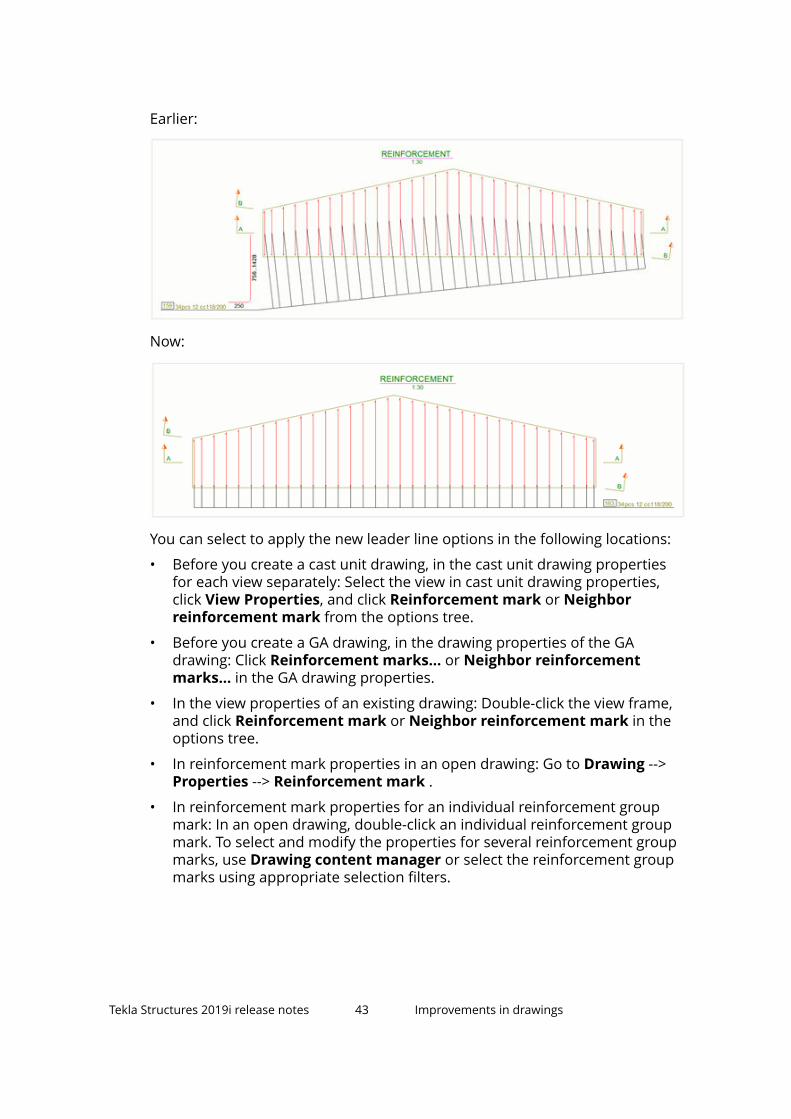
Earlier:
Now:
You can select to apply the new leader line options in the following locations:
• Before you create a cast unit drawing, in the cast unit drawing propertiesfor each view separately: Select the view in cast unit drawing properties,click View Properties, and click Reinforcement mark or Neighborreinforcement mark from the options tree.
• Before you create a GA drawing, in the drawing properties of the GAdrawing: Click Reinforcement marks... or Neighbor reinforcementmarks... in the GA drawing properties.
• In the view properties of an existing drawing: Double-click the view frame,and click Reinforcement mark or Neighbor reinforcement mark in theoptions tree.
• In reinforcement mark properties in an open drawing: Go to Drawing -->Properties --> Reinforcement mark .
• In reinforcement mark properties for an individual reinforcement groupmark: In an open drawing, double-click an individual reinforcement groupmark. To select and modify the properties for several reinforcement groupmarks, use Drawing content manager or select the reinforcement groupmarks using appropriate selection filters.
Tekla Structures 2019i release notes 43 Improvements in drawings

Improvements in dimensioning• View-specific dimensioning: The dimensioning type Shape dimensions
has new options for controlling which faces will be dimensioned. Byselecting the Visible faces option, dimensions will be created only to facesthat are visible in the drawing view. The other option All faces dimensionsall faces, similarly as shape dimensioning was doing previously. All faces isthe default value, and it will be used if the dimension settings file does notcontain any value for the new setting.
• It is now possible to associate dimensions to object center lines outside theobject area.
• Dimensioning plug-ins DLLs can now be found in sub-folders of <TeklaStructures binary folder>\plugins\Tekla\Drawings\Dimensioning\ and in environment in the sub-folders of \common\extensions\custom\dimensioning\. Previously all the DLLs wereexpected to be at the same level in those folders. This enables a betterseparation of each plug-in dependencies.
Improvements in dimension tags
Tags allow you to display the properties and other related information of theassociated building objects in dimensions and dimension sets. This feature hasnow been improved in several ways to make it work more consistently andreliably.
Display any object type in dimension tag marks
In the Dimension Properties dialog box on the Tags tab, you can define thecontents of the dimension tags of building object dimensions. The logic fordisplaying the contents has changed, and now all the building objectcategories are checked for content availability. The properties in the first found
Tekla Structures 2019i release notes 44 Improvements in drawings

category that has content are read and displayed in the tag. If you do not wantto display tag contents for some building objects, you can create anappropriate exclusion filter for this building object type. This means that youcan now display properties related to any associated object regardless of itstype and order in the hierarchy.
The reading order of building object content categories is the same as inearlier versions:
1. Surface treatment
2. Bolt
3. Rebar
4. Part/Pour object
Earlier, when a dimension was associated to several different building objecttypes, the properties of one category only were read and displayed in the tags.The category from which the properties were read based on a hidden readingorder. The main problem was that if several object types were selected forcreating dimensions, only the properties of object type that was higher in thereading order hierarchy were displayed in the tag. For example, if all the othercategories were empty, and the Part category had content, nothing wasdisplayed in the tag, because the Surface treatment category had no content.
Dimension tag contents now updated correctly
• Dimension tag contents are now updated correctly when you dragdimension points.
• Dimension tag contents are now updated instantly when you add orremove dimension points. Previously, the contents were not updated whenthe dimension became associative to another building object.
Improvements in Document manager
For more information about Document manager, see Document manager.
New indicator for cells that cannot be edited
• When the edit switch is active in Document manager, and you movethe mouse cursor over a cell that cannot be edited, the cursor now changesto indicate that you cannot edit the cell:
Tekla Structures 2019i release notes 45 Improvements in drawings

New category association options
The Edit category and New category dialog boxes in Document managernow have a new setting Association type, which defines if a category is searchbased, manual, or both.
• If the category is of type Search only or Manual and search, you need todefine a Search string in the dialog box.
• If you create a category by first selecting documents from the documentslist, the association type is Manual only by default.
• If you create a category from the category list, the association type isSearch only by default.
• You can change the association type later. If you change the type fromSearch only to Manual only, a message is displayed telling that the searchstring for that particular category will be cleared. If you change the typefrom Manual only to Search only or Manual and search, you need todefine a Search string.
New button Show all documents
• A new button Show all documents has been added to Documentmanager. This button resets the document list so that all documents arevisible, and all searches and filtering are cleared. Excluded categoriesremain excluded. This new feature also provides a convenient way torestore the document list to a default state when recording macros.
Invert document visibility/Reset document visibility
Now when you activate the Invert document visibility switch, the nameof the switch changes to Reset document visibility to indicate that clickingthe button again will reset the visibility and not invert the visibility a secondtime.
Other Document manager improvements
• Document manager search box now supports macro recording andplayback.
1.11 Improvements in rebar drawing toolsTekla Structures 2019i introduces some improvements in Rebar groupmarking, Rebar pull-out picture and marking, and Rebar groupdimensioning.
Tekla Structures 2019i release notes 46 Improvements in rebar drawing tools

Rebar group marking• The Rebar group marking application now works with circular rebar
groups.
• The Lines and symbol tab has new settings for drawing a symbol at theintersection of distribution lines and leader lines. The functionality forrebar symbols has been moved to the new Symbols on rebars tab.
• A new setting has been added on the Mark 1 tab to set the mark distancefrom the leader line.
For more information, see Add reinforcement marks with Rebar groupmarking application.
Tekla Structures 2019i release notes 47 Improvements in rebar drawing tools

Rebar pull-out picture and marking• On the Dimensions tab, you can now select whether to round according to
the user settings or according to the rebar_config.inp.
• Rebar pull-out picture and marking no longer creates duplicate pull-outpictures. The same fix was made in the Draw rebar pull-outs application.
For more information, see Draw rebar pull-out pictures with Rebar pull-outpicture and marking application.
Rebar group dimensioning• A new Group dimensions setting was added on the Advanced settings
tab to control if dimensions are grouped or not. Grouping now works alsowhen the distance between the groups is zero.
• Invisible color can now be applied on rebar lines and symbols.
• Rebar group dimensioning now dimensions rebar groups in polybeams.
For more information, see Dimension rebars with Rebar group dimensioningapplication.
1.12 Printing to multiple printers and other printingimprovementsStarting from Tekla Structures 2019i, you can print to more than one printer inone go based on the paper size of each selected drawing. When printing tomultiple printers you typically have different printers for handling differentpaper sizes. Tekla Structures automatically selects the appropriate printer foreach drawing.
For more information about printing, see Print to a .pdf file, plot file (.plt) orprinter.
Print drawings to multiple printers in one go
The Print Drawings dialog box now has a new control for printing to multipleprinters: Use multiple printers. When you want to print to a single printer, or
Tekla Structures 2019i release notes 48 Printing to multiple printers and other printingimprovements

define single printer settings to be used in multiple printing, select Use oneprinter.
Create single printing settings
To print to multiple printers, you first need to create single printing settings foreach of the printers you want to print to:
• Select Use one printer, and define the printing properties as desired.Select the output type and printer, and define the paper size that thisprinter will handle in the Use multiple printers mode. Then give thesettings a unique name and click Save. Repeat this for each of the desiredpaper sizes. Do not use the size option Auto.
For example, you can create the following single printer settings files withthe output type set to PDF file:
• PDF A4: Paper size set to A4, file prefix set to A4_• PDF A3: Paper size set to A3, file prefix set to A3_• PDF A2: Paper size set to A2, file prefix set to A2_
• When printing a set of drawings in the multiple printers mode using theabove single printer settings files, all A4 drawings will generate .pdf fileswith prefix A4_, all A3 drawings will have prefix A3_, and all A2 drawing willgenerate .pdf files with prefix A2_.
• If you want to print more than one sheet size to the same printer in theUse multiple printers mode, create a single printer settings file for eachpaper size, and specify the same printer in all of these files.
Tekla Structures 2019i release notes 49 Printing to multiple printers and other printingimprovements

Print to multiple printers
Change to the Use multiple printers mode, and in the Selected singleprinter settings files list, select the settings files to use in printing. You canselect all or just some of the single printer settings files.
Tekla Structures 2019i release notes 50 Printing to multiple printers and other printingimprovements

The output type (printer, plot file, PDF file) is defined by each selected singleprinter settings file. Typically you would select settings files with the sameoutput type. Output types lists the output types that are specified in theselected single printer settings files.
Change other necessary settings. When the output type of the selectedsettings files is Plot file or PDF file, you can change the following properties.These settings cannot be changed if the output type is Printer:
• File location: Where to create the output files. If the selected settings filesspecify a subfolder, then the output path is the combination of the mainpath and the subfolder path, which allows each settings file to specify adifferent subfolder. You can also specify an absolute path in each selectedsettings file, which will override the main path.
Example:
Main path: .\PlotfilesSettings file 1 subfolder path: A4Output result for settings file 1: .\Plotfiles\A4\
• Include revision mark to file name
• File prefix: Each selected settings file can override this.
• File suffix: Each selected settings file can override this.
• Fit to paper
• Scale
• Center drawing on paper
Tekla Structures 2019i release notes 51 Printing to multiple printers and other printingimprovements

• Print on multiple sheets
• Orientation
• Number of copies
• Collate
• Note that you cannot change the paper size, it is already included in theselected settings files. You can see the selected paper sizes listed in thedialog box.
• You can also save the multiple printing settings to a settings file for futureuse. Note that the multiple printing settings files are saved in the samelocation as the single printer settings files (<model>\attributes) but witha different file name suffix PdfMultiPrintOptions. For single printersettings, the suffix is PdfPrintOptions. This ensures that the settings arekept separate from the single printer settings.
• Click Print to print to multiple printers.
Other printing improvements• The Print Drawings dialog box now displays a message in the status area if
it is not possible to print due to invalid printing settings.
1.13 Improvements in Tekla Model SharingTekla Structures 2019i introduces several improvements regarding Tekla ModelSharing. For example, reasons of write out failures are now stored in log filesto simplify troubleshooting, and pour management is more robust than everbefore.
Reasons of write out failures are stored in log files
If writing out model changes fails, the reasons for the failure are now saved inthe error log and the model sharing log.
In the error_<user>_<YYYYMMDD>_<HHMMSS>.log file, you can find thereasons why Tekla Structures has failed to restore or save a file, or to write amaterial report export file or profile export file.
In the modelsharing.log file, you can find the reasons why creating data inthe write out has failed. These errors can happen because of several reasons,such as low disk space, database errors, or using a user role that does notpermit making certain changes.
Tekla Structures 2019i release notes 52 Improvements in Tekla Model Sharing

Improved pour management
Pour management in shared models has been improved significantly.Unexpected conflicts have been addressed, so working with pour units is saferand more efficient than ever before.
Earlier, pour management could cause conflicts when reading in other users'changes, and as a result, objects in pour units might have been accidentallyremoved.
Improved and more robust sharing operationsSharing operations now work more reliably even when other software arelocking some of the files needed to perform the operations. For example, if afile that is needed to create a packet is opened by anti-virus software, TeklaStructures can still create the packet without errors.
1.14 Changes in Tekla Structures installationStarting from Tekla Structures 2019 SP1, you can select in the environmentinstallation wizard that the environment .tsep files are installed whenrunning the installation wizard. If you do not select to install the .tsep filesautomatically, the files are installed when you start Tekla Structures for thefirst time after installation.
Note that if you are installing more than one environment for the first time, werecommend that you install the .tsep files by starting Tekla Structures.
1.15 New structure of firm and project foldersYou can now create user-defined sub-folders under the firm and projectfolders and store property files in the sub-folders. This means that you canhave a more organized folder structure in the project and firm folders. TeklaStructures can read and copy the property files from the sub-folders whenneeded. For example, property files are copied when you start sharing amodel.
Note that property files cannot be read from the following pre-defined sub-folders under the firm and project folders:
• ProjectOrganizerData• ProjectOrganizerData\DefaultCategoryTrees• ProjectOrganizerData\PropertyTemplates
Tekla Structures 2019i release notes 53 Changes in Tekla Structures installation

• ProjectOrganizerData\ExcelTemplates• AdditionalIPSets• macros
• macros\drawings• macros\modeling
• Drawing Details• extensions
• extensions\drawings• extensions\model
• CustomInquiry• PropertyRepository\Templates• symbols• template
• template\mark• template\settings• template\tooltips
• profil• profil\ShapeGeometries• profil\Shapes
• Environment folders
Tekla Structures searches for property files in the sub-folders of the firm folderor the project folder as follows:
1. The search starts from the root folder (XS_FIRM or XS_PROJECT).
2. If Tekla Structures finds the first property file with a corresponding filename suffix and file name prefix, the property file is selected.
3. The search continues so that each sub-folder of the root folder issearched in alphabetical order.
4. Tekla Structures ignores each attribute file with the same file name suffixand file name prefix as the previously selected file, and stores each filename in the error log.
1.16 Interoperability improvementsTekla Structures 2019i contains improvements in reference models, IFC objectconversion, IFC export, and point cloud functionality.
Tekla Structures 2019i release notes 54 Interoperability improvements

Reference models
Reference model object locking
• Reference model objects can no longer be locked. Locking preventedmodel update, caused confusion and increased the size of the database.Object lock has been used for locking model location. We recommend thatyou use model lock instead and set XS_REFRESH_ALSO_LOCKED_REFERENCE_MODELS to TRUE.
For more information about locking reference models, see Lock referencemodels.
.db1 as reference model format
• The .db1 format has been removed from the supported reference modelformats. You can still enable the .db1 format in the Add model dialog boxby setting the advanced optionXS_ENABLE_NATIVE_MODEL_AS_REFERENCE_MODEL to TRUE in an .inifile. Originally, this format was added in the Add model dialog box fortesting purposes.
Calculate new offsets when Location by is changed
• Reference model Location by change logic has been improved. By default,the location by change does not keep the reference model location. A newcheck box was added to calculate new offsets and keep the currentreference model location.
New reference model template attributes
• Reference model properties Code, Title, Phase, Description and Groupare now available as template attributes for reports.
Other reference model improvements
• When you refresh reference models that have been created with previousversions of Tekla Structures, the reference model information is nowupdated to match the version of Tekla Structures that you are currentlyusing.
• The performance of the reference model insert has been improved whenthe Tekla Structures model already contains non-visible unloaded referencemodels. After the fix, non-visible reference models are not loaded anymorein the reference model insert.
• Now it is possible to use 3D image files (.obj) as reference models.
Tekla Structures 2019i release notes 55 Interoperability improvements

IFC object conversion• IFC object conversion of steel contour plates now uses the prefix defined
for plates in Components settings ( File --> Settings --> Options --> Profilename --> Plate ) as the prefix for Tekla Structures native plates. You canuse prefixes that are supported by your environment.
• Arbitrary profile mapping by name does not need to match thedimensions. Arbitrary profile mapping by name can be set to requiredimensions to match by setting the new advanced option XS_CONVERSION_ARBITRARY_PROFILE_MAPPING_BY_NAME_MUST_MATCH_DIMENSIONS to TRUE. The default is FALSE.
• Parametric profile conversion by profile name mapping does not need tomatch the dimensions. Parametric profile conversion tries to find acorresponding library profile and if a profile does not match theparameters, the default parametric profile will be used.
For more information, see Convert IFC objects into native Tekla Structuresobjects.
IFC export
IFC2x3 export
• You can now also export radial grids in the IFC2x3 export.
• Edge chamfers are omitted from the exported IFC model. This is to enablebetter interoperability with plant design systems. If the geometry with edgechamfers is needed, you can set the IFC export type to B-rep separately forthose objects in the objects' user-defined attributes dialog box on the IFCexport tab.
IFC4 export
• The IFC4 Export now contains a new export type IFC4precast view. TheIFC4precast view aims to support the fabrication data transfer workflow ofprecast elements. At the first phase it covers the fabrication of precastwalls and slabs including all the needed reinforcement and embeds.
For more information, see Export a Tekla Structures model or selected modelobjects to an IFC file and IFC4precast.
Tekla Structures 2019i release notes 56 Interoperability improvements

Point clouds• You can now use point clouds through internet. There is a new URL option
in the Attach point cloud dialog box where you can enter the URLaddress.
• Point cloud web streaming cache has been added. The cache is a commoncache with Trimble Connect for Desktop. You can define the cache folderusing the advanced option XS_POINT_CLOUDS_WEB_CACHE in the FileLocations category of the Advanced Options dialog box. The cache usageimproves the performance of the web streamed point clouds.
For more information, see Point clouds.
1.17 Export to 3D DGN v8 - New 3D DGN exportThe 3D DGN export has been renewed.
The new 3D DGN v8 uses Teigha libraries and has some new features:
• The 3D DGN export now has the requested v8 format, and base pointfunctionality.
• There are several new export settings available in the new 3D DNG v8export. In the old 3D DGN export, you could only define the export filename and location, and select whether to export all objects or selectedobjects.
• The surface presentation of the parts is exported. Bolt holes are notincluded in the export.
• You can now export objects relative to the model origin, to the base pointyou define, or to the work plane.
• You can now export in layers by name, phase or any template attribute oruser-defined attribute.
• Colors can be exported by class or by stored object representation.
Tekla Structures 2019i release notes 57 Export to 3D DGN v8 - New 3D DGN export

• You can export all objects or selected objects. You can use the Select partsand Select objects in components selection switches for selecting theobjects to export.
• The old 3D DGN v7 export is still available in File --> Export --> 3D DGN .
Create object group color representationsIf you want to use object group color representations in the export, you needto create the object groups first and then set the colors for the object groups.Note that the transparency setting is not included in the export.
For more information, see Create object groups, and Change the color of anobject group.
Create base pointsIf you want to export objects relative to a base point, you need to create a basepoint in your model. For more information, see Base points.
Export to 3D DGN v8• To start the export, go to the File menu, and click Export --> 3D DGN v8 .
• Define the file name and folder.
• In Location by, select whether you want to export by model origin, by workplane, or by a defined base point.
• Select All objects or Selected objects.
Tekla Structures 2019i release notes 58 Export to 3D DGN v8 - New 3D DGN export

• If you want to export selected objects, select the objects with theappropriate selection switches:
• If you activate the parts selection or the objects in componentsselection, all the selected parts will be exported.
• If you activate the assembly selection, nothing will be exported.
• If you activate the component selection, nothing will be exported.
• In Object color, select whether you want to export objects using objectclass colors or object group colors. You can use phases, part names, ortemplate attributes as layer names for exported objects. Select Name orPhase from the list, or type the attribute name in the box. You can also useuser-defined attributes as a layer name.
• When you are done, click Export to export the objects according to thedefined settings.
• For more information about the export, see Export to 3D DGN.
1.18 Export to 3D DWG - New 3D DWG exportThe 3D DWG export has been renewed.
The new 3D DWG uses Teigha libraries and has some new features:
• The 3D DWG export now has the base point functionality.
• There are several new export settings available in the new 3D DWG export.
• The surface presentation of the parts is exported. Bolt holes are notincluded in the export.
• You can now export objects relative to the model origin, to the base pointyou define, or to the work plane.
• You can now export in layers by name, phase or any template attribute oruser-defined attribute.
• Colors can be exported by class or by stored object representation.
• You can export all objects or selected objects. You can use the selectionswitches for selecting the parts or objects in components to export.
• The old 3D DWG/DXF export is still available in File --> Export --> 3DDWG/DXF .
Tekla Structures 2019i release notes 59 Export to 3D DWG - New 3D DWG export

Create object group color representationsIf you want to use object group color representations in the export, you needto create the object groups first and then set the colors for the object groups.Note that the transparency setting is also included in the export.
For more information, see Create object groups, and Change the color of anobject group.
Create base pointsIf you want to export objects relative to a base point, you need to create a basepoint in your model. For more information, see Base points.
Export to 3D DWG• To start the export, go to the File menu, and click Export --> 3D DWG .
• Define the file name and folder.
• In Location by, select whether you want to export by model origin, by workplane, or by a defined base point.
• Select All objects or Selected objects.
• If you want to export selected objects, select the objects with theappropriate selection switches:
• If you activate the parts selection or the objects in componentsselection, all the selected parts will be exported.
• If you activate the assembly selection, nothing will be exported.
Tekla Structures 2019i release notes 60 Export to 3D DWG - New 3D DWG export

• If you activate the component selection, nothing will be exported.
• In Object color, select whether you want to export objects using objectclass colors or object group colors. You can use phases, part names, ortemplate attributes as layer names for exported objects. Select Name orPhase from the list, or type the attribute name in the box. You can also useuser-defined attributes as a layer name.
• When you are done, click Export to export the objects according to thedefined settings.
• For more information about the export, see Export to 3D DWG or DXF.
1.19 Updates in tools for concrete fabricationExport Unitechnik (79), Export EliPlan file, and Export BVBS contain severalimprovements.
Export Unitechnik (79)Export Unitechnik (79) has been improved in the following ways:
• The settings Name of order and Drawing number on the HEADER blockdata specification tab and Slab number on the SLABDATE block dataspecification tab now have a new option File name sections. Select thisoption and specify a string consisting of numbers referring to the 6sections of the exported file name mask that are specified on the Main tab.You can type numbers 1 to 6, and delimiters , . _ and - in the free input fieldto export any combination of strings used in the file name, in any order.For example, 1-2-3, or 2_5_6. Use this option to ensure that both the stringsin the file name and within the file content match the expected project anddrawing numbers for successful file import.
• When using file name block options it is now possible to specify input textwithout delimiters.
• Main tab:
• It is now possible to use a selection filter to select the parts for exportwith the new Export using filter setting. You can use the selection filterfor including or excluding the parts from the export.
• SLABDATE block data specification tab:
• It is now possible to export the unloading type using the newUnloading type setting. Also, it is possible to set Unloading type andTransport type on the Unitechnik tab for precast concrete parts,which overrides the export dialog box setting.
• It is now possible to specify a user-defined concrete volume templateproperty for export using the Concrete volume setting.
Tekla Structures 2019i release notes 61 Updates in tools for concrete fabrication

• There is a new option for the Export project coordinates setting. Usethe new Yes, special variant A option to export Unitechnik files thatare compatible with the IDAT stacker software. The new option is onlyavailable for the 5.2b version of Unitechnik.
• Pallet tab:
• A Profile centerline to pallet centerline option has been added forthe Align in Y axis . With the Profile centerline to pallet centerlineoption, you can automatically align hollow-core slabs to the center ofthe pallet in Y direction.
• Validation tab:
• A new option Exclude all has been added for the setting Export othersto exclude the whole mesh from the export when it fails the validation.The option No has been renamed to Remove invalid mesh wires, andnow this option only excludes invalid mesh wires and not the wholemesh when some of the mesh wires fail the validation.
• TS configuration tab:
• New settings have been added on the TS configuration tab. TheRotate geometry setting applies the rotation angle calculated with thesettings Extra rotation and Auto-rotate on pallet. The WithSLABDATE rotation angle setting rotates the element and exports therotation angle as a value in the respective SLABDATE field.
• The Extend contour and add formwork option has been improved insituations where the contour needs to be extended into the -X or -Ydirection.
For more information, see Unitechnik.
Export EliPlan fileExport EliPlan file has been improved in the following ways:
• It is now possible to specify a selection filter using the setting Export usingfilter on the Parameters tab. The parts are selected on the basis of thespecified selection filter.
• Plotter data export has been improved.
For more information, see EliPLAN.
Tekla Structures 2019i release notes 62 Updates in tools for concrete fabrication

BVBS ExportBVBS Export has been improved in the following ways:
• The BVBS export now reports the diameter value as the nominal rebardiameter regardless of the XS_USE_ONLY_NOMINAL_REBAR_DIAMETERsetting, according to the specification.
• The Partner and Developer configurations were added to the list of allowedconfigurations.
• Parameters tab:
• You can now use multiple assembly template properties in the filename. Type the template properties in the File naming template boxand separate them with spaces. The combination will be separated byunderscores in the exported file name.
• The Drawing name source setting has a new option Assemblytemplate, and the Template option has been renamed toReinforcement template.
• Checking tab:
• Check cutting length has been renamed to Check reinforcement, andnew checking options have been added:
- Reinforcement diameters (separated with spaces)
- Minimum leg length for straight sections between the bends
- Maximum weight of individual bars
• Advanced tab:
• Click the Edit or New button under Private data block. The list ofproperty data types has been updated, and the following options arenow available:
- Reinforcement report property Integer, Float or Text
- User-defined attribute Integer, Float or Text
- Open API object property
- Assembly report property Integer, Float or Text
• You can now move up, move down, edit and remove private data blockexport items.
• BVBS Export now contains new options for rounding rebar lengths for2D bent bars. Mesh and 3D rebars are not affected.
To round the lengths, first select an option for the Round setting. Theoptions are:
YesUp - Uses the nearest rounding value.
Up - Rounds the lengths up.
Down - Rounds the lengths down.
Tekla Structures 2019i release notes 63 Updates in tools for concrete fabrication

The new option Round lengths to rounds the total rebar lengths in thecorresponding BVBS field in the header block, and the available valuesare 1, 5, 10, and 25.
The new option Round leg lengths to rounds the leg lengths in thegeometry block, and the available values are 1, 5, and 10. 1 is thedefault value for both options.
For more information, see BVBS.
1.20 Improvements in componentsThere are several improvements in concrete components and steelcomponents in Tekla Structures 2019i.
Concrete components
Rectangular areareinforcement (94)
You can use the new Rectangular area reinforcement(94) component to reinforced rectangular areas. Youcan create column and beam section reinforcementto the inside of a wall or a slab.
Select the part where the reinforcement is placed andpick two points to create the reinforcement. The partdefines the thickness of the reinforced area, and thetwo points define the geometry and the location ofthe reinforced area.
Automatedreinforcementlayout - Double teebeam (51)
On the Strand profile tab, a new option has beenadded to depress the strand in 3 positions instead of2 positions.
Pad footingreinforcement (77)
You can now define custom hooks for the primaryand secondary rebars.
Round columnreinforcement (82)
• On the Main bars tab, you can now define thehorizontal dimensions of the top and bottom
Tekla Structures 2019i release notes 64 Improvements in components

cranked bars as a distance between the center ofbars or as the outer distance of bars.
• On the Advanced (main bars) tab, you can nowselect whether the main bars are created as arebar group or as single rebars.
Braced girder (88),Braced girder (89)
There are now two new girder shapes available.
Rebar in beam (90) On the Stirrups, Stirrups 2 and Stirrups 3 tabs, youcan now select in Create stirrups whether stirrupsare created As separate groups or As one group.Define the stirrup group spacings for the separategroups on the stirrup spacing tabs.
Reinforced concretestair (95)
• The stairs part now has a new STAIR_WIDTH_TOTAL UDA that counts the totalstair width including the stringers.
• For bar type H, you can now set the name, class,prefix and start number separately for the top andbottom rebar.
Tekla Structures 2019i release notes 65 Improvements in components

• You can now enter a comment in the Comment
box for all types of rebars that the componentcreates.
• On the Stairs and landings tab, you can nowcreate openings or recesses (screed tray) in thebottom or the top landing.
The rebars defined on the following tabsautomatically avoid the openings created by thesenew opening/recess options: Bottom anchorbars, Top anchor bars, Z anchor bars, Meshbars (top/bottom), Bar A, Bar B, Bar C, Bar E, BarG, Bar K, and Landing end bars (bottom/top).
Concrete console(110), Concreteconsole (111)
On the Connection tab (Concrete console (110)) andAnchor tab (Concrete console (111)), you can nowenter 79 characters in the Tube bottom Commentbox. Previously, you could only enter 19 characters.
Note that due to this change, the components andproperty files created with older Tekla Structuresversions may have incorrect content in theComments of Tube bottom and Washers. Werecommend that you check and update your propertyfiles.
Floor layout • On the Advanced tab, you can now use theCreate cut-outs option to control whether thecut-outs (notches or openings) are created for theslabs. If you set the option to No, the slab iscreated without any cuts. Slabs at break lines oropenings which are cut at the whole width are stillsplit and created as two or more slabs.
Note that the other options on the Advanced tabrelated to the minimum slab width/neck width stillcontrol whether the slab is created/split or not.
You can create automatic cut-outs for partspenetrating the floor layout areas by entering upto three lists of part classes or names.
• On the General tab, you can now select to createslabs and parts by default part width or maximumpart width, or the number of parts.
• You can now enter a negative value for the breakline offset on the Default offset tab.
Wall layout You can now use the Copy special > Mirror andMove special > Mirror commands to mirror walllayouts.
Tekla Structures 2019i release notes 66 Improvements in components

Wall panelreinforcement
• On Picture tab, there is now a minimum barlength option that you can use for filtering rebarssmaller than the defined length.
• On the Picture tab, you can now define the topand bottom extra offset.
Double wall edgeand openingreinforcement, Wallpanel reinforcement
You can now define the type of door and notchreinforcement on the new Door and Notch tabs.
Sandwich anddouble wall
• On the Parts tab, there is now a new materialdefinition option for insulation, Edge strips insplit case, which can be used to define a differentmaterial for the insulation parts that are on theedge of the wall.
• On the Parts tab, you can now set the cast unittype of the inside shell, insulation, and outsideshell. Set the Cast unit type to Enabled to do this.
• On the Vertical section tab, there is a new optionfor creating concrete all over the top surface.
In the list of thicken innershell options, select
to cover the insulation and the outer shell.
Tekla Structures 2019i release notes 67 Improvements in components

Sandwich wallhorizontal seam
On the Rabbets tab, you can now select a tongue orgroove joint connection for both sides of thesandwich wall. If you create one tongue and onegroove connection, it is possible to have the partsoverlap.
Tekla Structures 2019i release notes 68 Improvements in components

Mesh bars/Meshbars by area
• When detailing without grid on the Detailing tab,you can now select whether the distances are thesame or different for the top and bottom bars.Using different distances helps in placing top andbottom hooks so that they do not collide, forexample.
• When defining the Spacing type on the Picturetab, you can now select to set the spacing by exactspacings. List the distances between the bars inthe Spacing box.
Steel components
Base plate (1004),Stiffened base plate(1014), U.S. Base plate(1047), Joining plates(14), Stiffened end plate(27), Partial stiff endplate (65), Two sidedend plate (142), Endplate (144)
It is now possible to create two new types of shimplates where the shim plate is created as twoseparate plates divided horizontally or verticallywith the corresponding slots.
Tekla Structures 2019i release notes 69 Improvements in components

Tube crossing (22) On the Brace conn tab, you can now define a gapbetween the gusset and the connection plates.
Tube gusset (20), Tubecrossing (22)
On the Brace conn tab, you can now to set theposition of the middle end plate.
Shear Pl to tube column(47)
• You can now define the bolt propertiesseparately for the primary and secondarybolts.
• You can now define the radius of the top andbottom beam cut on the Primary andSecondary tabs.
Tekla Structures 2019i release notes 70 Improvements in components

Purlin 1 (61) On the Bolts tab, you can now select from the
Slots in list the parts in which slotted holes arecreated.
Partial stiff end plate(65)
You can now define the distance between an Lprofile end and the top of the main part.
Railings (S77) You can now define separate position and rotationsettings for the top and bottom rails on the Railstab and for the middle rails on the Middle Railstab.
Bridging (80) There are now 4 new bridging types available onthe Parameters tab: Stratco, Safebridge,Metroll, and Steel and Tube.
End plate (101) You can now align the end plate with thesecondary part slope using the Adapt tosecondary part slope option on the End platetab.
Stub connection (119) You can now set the thickness, material and nameseparately for the top, back and middle stiffenerson the Parts tab.
Full depth (184), Columnwith stiffeners (186),Column with stiffeners(188)
On the Plates tab, you can now select whetherthe shear tab is cut parallel to the main part web.
JP Full depth special(185)
You can now define the inner shear tab chamfersand the chamfer dimensions on the Plates tab.
Tekla Structures 2019i release notes 71 Improvements in components

Stiffeners (1003) • You can now rotate the stiffener polygons on
the Parameters tab. You can set the rotationfor both the right and the left stiffener.
• You can now define the stiffener plate distancefrom the beam flange on the Picture tab.
Stiffened base plate(1014)
You can now select to create two grout holes onthe Parameters tab.
Doubler plate (1022) You can now use separate settings for horizontaland vertical welds.
Stiffeners (1034) It is now possible to create a weld between thebottom flange of the main part and the stiffenerplate using weld 2, and a weld between the topflange of the main part and the stiffener plateusing weld 3.
Tekla Structures 2019i release notes 72 Improvements in components

1.21 Changes in advanced options
New advanced options• XS_REBARSET_SHOW_GUIDELINES
• XS_REBARSET_SHOW_MODIFIERS_CREATED_BY_COMPONENTS
• XS_REBARSET_CREATION_ANGLE_TOLERANCE_FOR_LONGITUDINAL_REBARS
• XS_REBARSET_CREATION_ANGLE_TOLERANCE_FOR_CROSSING_REBARS
• XS_REBAR_MINIMUM_LEG_DEVIATION
• XS_REBAR_COMBINE_BENDINGS_IN_EVALUATOR
• XS_CONVERSION_ARBITRARY_PROFILE_MAPPING_BY_NAME_MUST_MATCH_DIMENSIONS
• XS_MARK_LEADER_LINE_LENGTH_FOR_PERPENDICULAR
• XS_POINT_CLOUDS_WEB_CACHE
Tekla Structures 2019i release notes 73 Changes in advanced options

2 Tekla Structures 2019iadministrator's release notes
Upgrade guide from Tekla Structures 2019 to Tekla Structures 2019i
Administrator's release notes are intended to provide advanced users withinstructions on how to apply the additional customizations available in a newTekla Structures version.
Administrator's release notes: General settings (page 74)
Administrator's release notes: Steel settings (page 101)
Administrator's release notes: Concrete settings (page 102)
2.1 Administrator's release notes: General settingsGeneral customization settings apply to all user groups. Use these settingstogether with your own user group settings.
Administrator's release notes: Model templates in version update (page 75)
Administrator's release notes: Applications & components catalogmaintenance (page 78)
Administrator's release notes: New structure of firm and project folders(page 79)
Administrator's release notes: Lofted plate and lofted slab (page 81)
Administrator's release notes: UDA handling in the property pane (page 82)
Administrator's release notes: Multiple printing settings (page 94)
Administrator's release notes: Improvements in drawings (page 94)
Administrator's release notes: Improvements in marks (page 96)
Administrator's release notes: Interoperability improvements (page 99)
Tekla Structures 2019i administrator's releasenotes
74 Administrator's release notes: General settings

Administrator's release notes: Model templates in versionupdate1. Open Tekla Structures 2019i.
2. Create a new model using an existing model template.
3. Give the model the same name as in the previous Tekla Structuresversion.
4. Open a 3D view.
5. Diagnose and repair the model.
Tekla Structures 2019i administrator's releasenotes
75 Administrator's release notes: General settings

6. Create a project thumbnail, or add a custom image namedthumbnail.png in the model folder.
The preferred size of the image is 120 x 74 pixels.
Tekla Structures 2019i administrator's releasenotes
76 Administrator's release notes: General settings

7. Save the model.
If you do not do this, a message may appear warning about the modelbeing created with a previous version.
8. Save the model as a model template.
9. Include the needed catalog files and subfolders from the model folder,and click OK.
10. Remove manually all *.db files (environment database, optionsdatabases) from the model folder.
Tekla Structures 2019i administrator's releasenotes
77 Administrator's release notes: General settings

The *.bak, *.log and xs_user files are automatically removed from themodel folder.
The .idrm files (db.idrm and xslib.idrm) should be kept as they arepart of the model.
The model template is saved in a location pointed by XS_MODEL_TEMPLATE_DIRECTORY.
You now have a sample image for your model template. The Applications& components catalog is now also in order and easy to use.
Administrator's release notes: Applications & componentscatalog maintenanceKeep the Applications & components catalog in shape and usable. For moreinformation about the Applications & components catalog, see How to usethe Applications & components catalog.
Set XS_COMPONENT_CATALOG_ALLOW_SYSTEM_EDIT to TRUE to be able to editthe Applications & components catalog definition files that are located in the XS_SYSTEM folders.
Check and fix the following:
1. Add the items to groups
Check Ungrouped items and add the items to the appropriate group.
2. Check the logs for errors
Tekla Structures 2019i administrator's releasenotes
78 Administrator's release notes: General settings

The Applications & components catalog shows the message log buttonin the lower-right corner of the catalog if there are errors or warnings in thecatalog definition files, for example.
If there are references to missing plug-ins, go to the referredComponentCatalog.xml and remove the references manually:
Test thoroughly that these changes do not create any further errors, or changethe structure of your Applications & components catalog. Check at least theUngrouped items and Legacy catalog groups.
As in the example above, there may be errors for:
• CatalogPluginComponentItem?CopyModelDirectoryPlugin• CatalogPluginComponentItem?SaveAsModelTemplatePlugin3. Hide all non-related applications and components from roles
1. In the Ungrouped items catalog, select the Show hidden items checkbox at the bottom.
2. Right-click an application or a component and select Hide / Unhide.
4. Create custom thumbnails
Publish a component in the Applications & components catalog
You may need to use the same component with different settings in differentcases. To easily use the component, you can define the settings for each caseand publish the component in the catalog. This feature can be useful for someroles.
Tekla Structures 2019i administrator's releasenotes
79 Administrator's release notes: General settings

Administrator's release notes: New structure of firm andproject folders
You can now create user-defined sub-folders under the firm and projectfolders and store property files in the sub-folders. This means that you canhave a more organized folder structure in the project and firm folders. TeklaStructures can read and copy the property files from the sub-folders whenneeded. For example, property files are copied when you start sharing amodel.
Note that property files cannot be read from the following pre-defined sub-folders under the firm and project folders:
• ProjectOrganizerData• ProjectOrganizerData\DefaultCategoryTrees• ProjectOrganizerData\PropertyTemplates• ProjectOrganizerData\ExcelTemplates
• AdditionalIPSets• macros
• macros\drawings• macros\modeling
• Drawing Details• extensions
• extensions\drawings• extensions\model
• CustomInquiry• PropertyRepository\Templates• symbols• template
• template\mark• template\settings• template\tooltips
• profil• profil\ShapeGeometries• profil\Shapes
• Environment folders
Tekla Structures searches for property files in the sub-folders of the firm folderor the project folder as follows:
Tekla Structures 2019i administrator's releasenotes
80 Administrator's release notes: General settings

1. The search starts from the root folder (XS_FIRM or XS_PROJECT).
2. If Tekla Structures finds the first property file with a corresponding filename suffix and file name prefix, the property file is selected.
3. The search continues so that each sub-folder of the root folder issearched in alphabetical order.
4. Tekla Structures ignores each attribute file with the same file name suffixand file name prefix as the previously selected file, and stores each filename in the error log.
Administrator's release notes: Lofted plate and lofted slabTekla Structures 2019i introduces new part types: steel lofted plate andconcrete lofted slab. Use lofted plates to model rolled plates and plates withdouble-curved form, for example. Use lofted slabs to model curved anddouble-curved slabs or walls, for example.
For more information, see New part types: lofted plate and lofted slab(page 22)
Lofted plate
Current configuration in the common environment...\2019.1\Environments\common\system\standard.lpl
Tekla Structures 2019i administrator's releasenotes
81 Administrator's release notes: General settings

Lofted slab
Current configuration in the common environment...\2019.1\Environments\common\system\standard.lsl
To do
Create new settings and save them. The new settings files can be found from:
\<model>\attributes\<SettingName> - lsl.
\<model>\attributes\<SettingName> - lpl.
Save the files to the wanted folder in the XS_SYSTEM path.
The files will be searched from XS_PROJECT, XS_FIRM, XS_DRIVER, XS_SYSTEM and XS_USER_SETTINGS_DIRECTORY.
Tekla Structures 2019i administrator's releasenotes
82 Administrator's release notes: General settings

Administrator's release notes: UDA handling in theproperty paneTekla Structures 2019i introduces improvements in the property pane and theProperty pane editor. With these updates, especially the viewing andmodifying of user-defined attributes (UDAs) is now easier and morestraightforward.
Tekla Structures 2019i administrator's releasenotes
83 Administrator's release notes: General settings

For more information, see Updates to the property pane, UDAs, and to theProperty pane editor (page 11).
To do
Configure the wanted area-specific UDAs to the property pane. You can selectto add them all or just the most commonly used UDAs.
Tekla Structures 2019i administrator's releasenotes
84 Administrator's release notes: General settings

The customized settings files can be found from: ..\Users\<user>\AppData\Local\Trimble\Tekla Structures\<version>\UI\PropertyTemplates\PropertyTemplates.xml.
Move the file to the wanted folder in the XS_SYSTEM path ...\PropertyRepository\Templates\.
Note
The property pane searches the configuration files from the model folder, and XS_PROJECT, XS_FIRM, XS_DRIVER, and XS_SYSTEM folders.
Groups that are defined in different PropertyTemplates.xml files are notmerged for object types. However, if the property template in a higher priorityfolder does not contain any definition for an object type, the definition in alower priority folder will be used for that object type. Merging does not workwithin object types but it works between object types.
If the file exists in ..\Users\<user>\AppData\Local\Trimble\TeklaStructures\<version>\UI\PropertyTemplates\, it will be used.
Set default values automatically -option
Set default values automatically option is under the Visibility of propertiesbutton. The default status of the option is checked and Modify button worksas before. When it is unchecked, Set as default button will be visible inproperty pane and works as the old Apply button. In this state, the Modifybutton does not automatically apply the edited properties for the next objectcreation.
This is also possible to configure in the PropertyTemplates.xml file.
Tekla Structures 2019i administrator's releasenotes
85 Administrator's release notes: General settings

Localization tasksThe aim is to have good UDA grouping for all available UDAs within each role,and to choose which carefully chosen groups should be visible by default in
Tekla Structures 2019i administrator's releasenotes
86 Administrator's release notes: General settings

each role. The result should be clean, practical and easy-to-understand,without reporting any warnings to user due to missing UDAs.
We recommend that you create the grouping in line with the content of UDAtabs but this is a great opportunity to streamline them and sub-categorizethem to improve the user experience.
Tekla Structures 2019i administrator's releasenotes
87 Administrator's release notes: General settings

Which environments and roles need to be localized
• The PropertyTemplates.xml files for an environment need to beupdated if the environment contains environment-specific UDAs.
• The PropertyTemplates.xml file for a role needs to be updated if therole contains role-specific UDAs.
PropertyTemplates.xml files to be used as a starting point
The common environment contains four property template files with UDAsdefined in the common environment. When starting to localize your propertytemplates, you can use them as a starting point.
Known issues with the property templates:
• Grid UDAs cannot currently be added to the property pane
• All group titles do not have a translation yet
Steps to localize the property templates
1. Remove the existing PropertyTemplates.xml files from theenvironment so that they do not interfere with the new files you arecreating.
2. Start Tekla Structures with the role for which you want to localize, or therole with most UDAs if you are creating only one property template for anenvironment.
3. Set XS_ENABLE_POUR_MANAGEMENT to TRUE to see pour UDAs.
4. Select the best matching property template for your role/environment touse it as a starting point:
Template in folder UDAs in templateCommon Parameters, User fields, Product
information, Structural information,End conditions, Analysis, TeklaStructural Designer, IFC export,Unitechnik (for rebars), Couplers
ConstructionManagement All above + Workflow UDAsCIP All above + BVBS UDAsPrecast All above + Unitechnik (for parts),
EliPlan, HMS UDAs
5. Store the selected PropertyTemplates.xml file to the ..\Users\<user>\AppData\Local\Trimble\Tekla Structures\<version>\UI\PropertyTemplates folder.
Tekla Structures 2019i administrator's releasenotes
88 Administrator's release notes: General settings

6. Open Property pane editor.
7. For each object type, do the following:
a. Check which UDA tabs are available in the old UDA dialog box.
Tekla Structures 2019i administrator's releasenotes
89 Administrator's release notes: General settings

b. Add groups corresponding to the tabs in property pane. You candivide the tabs into several groups if needed.
Tekla Structures 2019i administrator's releasenotes
90 Administrator's release notes: General settings

c. Add the UDAs on each tab to the corresponding group in the propertypane. Note! Copy the tabs with the Copy properties command forobject types that have the same tabs.
Tekla Structures 2019i administrator's releasenotes
91 Administrator's release notes: General settings

d. Remove any UDAs that are not available in the role, as they willotherwise be reported as missing.
e. If you had a group Custom properties in your property template,rename it as More.
f. Hide other than the most frequently used groups by clicking the eyeicon in Property pane editor. This ensures that the property paneonly shows the content that you need.
g. Add labels for UDAs with the Rename command if the labels havebeen defined separately from the UDA in the objects.inp file.
Tekla Structures 2019i administrator's releasenotes
92 Administrator's release notes: General settings

h. Translations that exist in joints.ail or in another file in themessages folder can be used by typing translation:x_x_xx to theedit label Rename dialog box.
8. When ready, move the PropertyTemplates.xml file from ..\Users\<user>\AppData\Local\Trimble\Tekla Structures\<version>\UI\PropertyTemplates to the \PropertyRepository\Templatessubfolder in the environment or environment\role folder. Ensure that noproperty template remains in your \AppData folder, because the file inthe \AppData folder has the highest priority.
9. Open the property pane to test your property template.
The closest matches between the roles in the Default environment and theexample property templates:
Role Property templateCIP role CIP property templatePrecast role Precast property templateEngineering role Precast property templateSteel role Construction management property template
NOTE Groups that are defined in different PropertyTemplates.xml filesare not merged for any specific object type. However, if a propertytemplate in a higher priority folder does not contain any definition foran object type, the definition in a lower priority folder will be used forthat object type. So merging does not work within object types butbetween object types it works.
NOTE If the file exists in ..\Users\<user>\AppData\Local\Trimble\TeklaStructures\<version>\UI\PropertyTemplates\, it willbe used in property pane.
Any changes will only be saved to the file in your user data folder.Therefore, copy the environment file to be edited to the ..\Users\<user>\AppData\Local\Trimble\Tekla Structures
Tekla Structures 2019i administrator's releasenotes
93 Administrator's release notes: General settings

\<version>\UI\PropertyTemplates folder to ensure that allchanges are included in this one file. If you need to re-edit the filelater, copy the environment file again to the user data folder.
NOTE If your role is using a shared folder that is listed on the left side of therole-specific folder in the XS_SYSTEM path, ensure that there is noproperty template in that shared folder. Otherwise, the sharedproperty template will override your role-specific property template,because folders on the left have higher priority.
As mentioned, the files do not merge within an object type, so thefolder path with highest hierarchy will override the other propertytemplates, which ensures there will not be any mismatch due to roles.However, All roles might be missing UDA grouping for UDAs fromlower-ranking roles.
Administrator's release notes: Multiple printing settingsYou can print to more than one printer in one go based on the paper size ofeach selected drawing. You typically have different printers for handlingdifferent paper sizes. Tekla Structures automatically selects the appropriateprinter for each drawing.
To do
Create the new settings and save them. The newPdfMultiPrintOptions.xml settings file can be found from \<model>\attributes\<SettingName>.
Save the file to the wanted folder in the XS_SYSTEM path.
The file will be searched from XS_PROJECT, XS_FIRM, XS_DRIVER, XS_SYSTEM, and XS_USER_SETTINGS_DIRECTORY folders.
For more information about the new option to print to multiple printers in onego, see Printing to multiple printers and other printing improvements(page 48).
Administrator's release notes: Improvements in drawingsYou can now set the Fit by parts option for section views also before creatingthe drawings. There are also improvements in rebar drawing tools.
Cast unit drawing creation• In the drawing properties for section views, it is now possible to select Fit
by parts as an option to be used for the created section views.
Tekla Structures 2019i administrator's releasenotes
94 Administrator's release notes: General settings

Improvements in rebar drawing tools
Rebar group dimensioning
A new Group dimensions option has been added to the Advanced settingstab for controlling if dimensions are grouped or not. Grouping now works alsowhen the distance between the groups is zero.
Tekla Structures 2019i administrator's releasenotes
95 Administrator's release notes: General settings

Rebar group marking
• There is a new feature that adds symbols on the distribution and leaderline intersection. To add this feature, the Lines and symbol tab is nowdivided into 2 separate tabs.
• There is a new option on the Mark 1 tab to determine the offset from themark to the leader line.
For more information about improvements in rebar drawing tools, seeImprovements in rebar drawing tools (page 46).
Administrator's release notes: Improvements in marksThere are new options for rebar group marks. We also recommend that youchange the leader line default option for merged marks.
Merge marks
Currently, there is an option One leader line to group that shows only oneleader line. This could cause a misunderstanding because the mark is pointingto only one object in the group instead of all. This is difficult to notice becausethe merge functionality is automatic. Any other option adds leader lines to allobjects in the group.
For detailed instructions on how to merge marks, see Merge marks.
Tekla Structures 2019i administrator's releasenotes
96 Administrator's release notes: General settings

Examples
One leader line to group
Parallel leader lines
Tekla Structures 2019i administrator's releasenotes
97 Administrator's release notes: General settings

Leader lines to one point
To do
Localize the merged marks property to some other value than One leaderline to group.
• Drawing setting files (.ad, .wd, .cud, .gd)
• View setting files (.vi, .vpm, .vsm)
• Mark setting file (.pm)
Perpendicular leader line / Leader line to first and last• There is a new type of leader line for group rebar marks: Leader line to first
and last.
• There is a new advanced option for perpendicular leader line length:
XS_MARK_LEADER_LINE_LENGTH_FOR_PERPENDICULARThe XS_MARK_LEADER_LINE_LENGTH_FOR_PERPENDICULAR advancedoption now controls the leader line length in a similar way as the leader lineextension length controlled by XS_MARK_LEADER_LINE_EXTENSION_LENGTH.
Tekla Structures 2019i administrator's releasenotes
98 Administrator's release notes: General settings

Administrator's release notes: Interoperabilityimprovements
Export to 3D DWG settings
Standard file in the common environment
The standard file can be found in C:\ProgramData\Trimble\TeklaStructures\2019.1\Environments\common\system\standard.dwgExport.json.
Tekla Structures 2019i administrator's releasenotes
99 Administrator's release notes: General settings

For more information about the new 3D DWG export, see Export to 3D DWG -New 3D DWG export (page 59).
To do
Create new settings and save them. The new dwgExport.json settings filecan be found in \<model>\attributes\<SettingName>.
Save the file to the wanted folder in the XS_SYSTEM path.
The file will be searched from XS_PROJECT, XS_FIRM, XS_DRIVER, XS_SYSTEM, and XS_USER_SETTINGS_DIRECTORY.
Export to 3D DGN settings
Standard file in the common environment
The standard file can be found in C:\ProgramData\Trimble\TeklaStructures\2019.1\Environments\common\system\standard.dgnExport.json.
Tekla Structures 2019i administrator's releasenotes
100 Administrator's release notes: General settings

For more information about the new 3D DGN export, see Export to 3D DGN v8- New 3D DGN export (page 57).
To do
Create new settings and save them, if needed. The new dgnExport.jsonsettings file can be found in \<model>\attributes\<SettingName>.
Save the file to the wanted folder in the XS_SYSTEM path.
The file will be searched from XS_PROJECT, XS_FIRM, XS_DRIVER, XS_SYSTEM, and XS_USER_SETTINGS_DIRECTORY.
2.2 Administrator's release notes: Steel settingsThe following customization settings only apply to the steel user group.
Administrator's release notes: Steel components (page 101)
Administrator's release notes: Steel componentsThere are several improvements in steel components in Tekla Structures 2019i.
Update your standard files if you want to take the new options and featuresinto use.
For more information about these improvements, see Improvements incomponents (page 64) in Tekla Structures 2019i release notes.
Tekla Structures 2019i administrator's releasenotes
101 Administrator's release notes: Steel settings

2.3 Administrator's release notes: Concrete settingsThe following customization settings only apply to the concrete user group.
Administrator's release notes: Rebar sets and other reinforcementimprovements (page 102)
Administrator's release notes: Updates in tools for concrete fabrication(page 104)
Administrator's release notes: Concrete components (page 104)
Administrator's release notes: Rebar sets and otherreinforcement improvementsIn Tekla Structures 2019i, there are many new features related to rebar sets,and improvements in Rebar shape manager.
For additional information about these improvements, see also Improvementsin rebar sets and Rebar shape manager (page 32) in Tekla Structures 2019irelease notes.
Cranking using end detail modifiers
To do
Ensure that your environment's rebar database (rebar_database.inp) islocalized to cover the standard lapping and standard cranking functionalities.
Standard file update
Update your environment's end detail modifier standard file(standard.rst_edm):
1. Create a rebar set. Interrupt the command. Then select the rebar set.
2. Create an end detail modifier. Interrupt the command. Then select theend detail modifier.
The property pane opens.
3. Enter suitable standard values and save the file as standard.
4. Upload the newly created standard file again to your environment.
Face-specific concrete covers
To do
New standard file
Tekla Structures 2019i administrator's releasenotes
102 Administrator's release notes: Concrete settings

If needed, create a new surface object standard file and add it to yourenvironment (for example, Concrete cover.srfo and Concretecover.srfo.more):
1. Create a surface object. Interrupt the command. Then select the surfaceobject.
The property pane opens.
2. Enter suitable standard values and save the file as Concrete cover orsimilar.
3. Upload the newly created standard file again to your environment.
Manual grouping
To do
Standard file update
Update your environment's property modifier standard file(standard.rst_pm):
1. Create a rebar set. Interrupt the command. Then select the rebar set.
2. Create a property modifier. Interrupt the command. Then select theproperty modifier.
The property pane opens.
3. Enter suitable values and save the file as standard.
Tekla Structures 2019i administrator's releasenotes
103 Administrator's release notes: Concrete settings

4. Upload the newly created standard files again to your environment.
Report template update
Update your report templates to support this new functionality. Use thefollowing updated templates from the Default environment (\default\Concrete\Shared\ReportsAndTemplates) as an example:
• Rebar - Group Bending List - Compact.rpt• Rebar - Group Bending List - Extended.rpt• Rebar - Single Bar Bending List.rpt
Moving all rebar set related UDAs to one .inp filePreviously, rebar set related UDA definitions were in several separate .inpfiles. Now they are in one file to make it easier to maintain the UDAs.
To do
The objects_rebar_set.inp file is now located in the common\system\folder. If your environment does not follow common\system\, copy this file toyour environment's \inp folder and check if you get the rebar set UDAs.
Rebar shape managerThe following improvements have been made:
• There is a new tolerance setting Curve tolerance on the Tolerances tab.This value is used to recognize the ‘arc’ in a bar that has multiple sequentialbendings.
• Rebar shape manager has been changed so that multiple sequentialbendings that form an arc are combined into one or more bendings (90degree or less) with the arc radius.
Administrator's release notes: Updates in tools for concretefabrication
Export Unitechnik (79), and Export EliPlan file, and Export BVBS have beenimproved.
For more information about the improvements, see Updates in tools forconcrete fabrication (page 61) in Tekla Structures 2019i release notes.
Administrator's release notes: Concrete componentsThere are several improvements in concrete components in Tekla Structures2019i.
Tekla Structures 2019i administrator's releasenotes
104 Administrator's release notes: Concrete settings

Update your standard files if you want to take the new options and featuresinto use.
For more information about these improvements, see Improvements incomponents (page 64) in Tekla Structures 2019i release notes.
Tekla Structures 2019i administrator's releasenotes
105 Administrator's release notes: Concrete settings

3 Localization release notes
Environment-specific Tekla Structures localization release notes introduce newand changed features in the new Tekla Structures version from the localizationpoint of view. It lists the features that have been localized in your environmentand also helps you in your own customization tasks. The localization releasenotes are supplied by the localization teams at your local area and reselleroffices.
Localization release notes 106 Administrator's release notes: Concrete settings

4 Upgrade Tekla Structures to anew version
You can have many Tekla Structures versions on your computer. When youinstall and start using a new version, you do not need to uninstall the olderversions and you can keep using them. Service packs are cumulative updates,so they replace the previous service pack installation for the same TeklaStructures version.
NOTE We recommend that you complete any models you are already working onusing your current version of Tekla Structures. Once you save a model in thenew version, you cannot open it in the previous versions anymore.
You can download the installation packages from the Tekla Downloadsservice.
Complete the upgrade in this general order (follow the links in the text fordetailed instructions):
1. Update the Tekla license server (page 108). The updated version replacesthe existing version you have installed.
2. Renew your licenses as explained in Renew a Tekla license (page 109).
The renewed licenses can be used with the version indicated on thelicense and any previous versions that are compatible with your installedlicense server version.
3. Install Tekla Structures.
You can have many Tekla Structures versions and environments on yourcomputer. When you install and start using a new version, you do notneed to uninstall the older versions.
4. Copy personal settings to a new Tekla Structures version (page 110).
You can use the Migration Wizard (page 110) tool to copy some of thepersonal settings to the new version. You can skip the copying if you donot want to copy the settings, or if you want to copy the settings fromsome other Tekla Structures version than suggested in Migration Wizard.
Upgrade Tekla Structures to a new version 107 Administrator's release notes: Concrete settings

5. Transfer customized information to a new Tekla Structures version(page 111).
In the new Tekla Structures version, you can use the information you havecustomized in the previous version. We strongly recommend that youcreate project and firm folders, and store the files you customize in thesefolders. Tekla Structures does not replace the files in project and firmfolders when you install a new version. If you do not use project and firmfolders, you need to transfer the customized information to the newversion manually.
4.1 Update the Tekla license serverWe recommend that you have the newest version of Tekla license serversoftware installed on the Tekla license server. New versions of Tekla Structuresdo not always work at all with older license server versions.
You can use older versions of Tekla Structures with a newer version of thelicense server. In some older Tekla Structures versions, this requires that youhave installed recent enough updates; for more information about thecompatibility between Tekla Structures versions and Tekla license serverversions, see Which license server version to use.
To update the Tekla license server:
1. Save the model that you are working with and close Tekla Structuresbefore the server update.
2. Go to Tekla Licensing --> LMTOOLS through the Start menu or Startscreen, depending on your Windows operating system.
3. On the Stop/Start/Reread tab, click Stop Server to stop the Tekla licenseserver and any other licensing services.
When you have completed installing the Tekla license server, you canrestart the other licensing services.
4. Backup any files you have modified in the C:\Tekla\License\Serverfolder.
You do not need to back up tekla.lic or tekla.opt, because theinstaller will not changes these files.
5. Download the latest version of the Tekla license server and the optionalTekla License Borrow Tool (if you use it) from Tekla Downloads.
Upgrade Tekla Structures to a new version 108 Update the Tekla license server

6. Install the downloaded license server with administrator rights using theautomatic installation for normal setup. Follow the instructions displayedon the screen.
If the installation fails or the server does not start after installation, tryreinstalling with the local firewall and antispyware/antivirus protectiondisabled.
7. If you use the Tekla License Borrow Tool, install the new version of the toolon workstations that need it.
4.2 Renew a Tekla licenseLicense renewal means changing the details on an existing license, such asupdating the highest allowed software version or extending the validity periodof a temporary license. You deactivate the current license and then activate itagain with a new license entitlement certificate that contains the updatedinformation.
When you receive your renewed license, you must deactivate the existinglicense and then activate the new version of the license. Two versions of thesame license cannot be active at the same time. License deactivation andactivation is done on License server (which can also be the same computer onwhich Tekla Structures is installed) and requires an internet connection.
NOTE Before you deactivate licenses, ensure that the licenses are not in useor borrowed. To deactivate the licenses, users must return anyborrowed licenses as explained in Return a borrowed Tekla Structureslicense.
To renew a license:
1. Rename your previous entitlement certificate file in the license serverinstallation folder (by default C:\Tekla\License\Server) fromEntitlementCertificate.html to EntitlementCertificate-OLD.html.
2. Save the entitlement certificate file to the license server installation folder.
The person in your organization who has made the license purchase, orsomeone named as the contact person, receives a newEntitlementCertificate.html entitlement certificate by e-mail as anattachment.
3. Go to Tekla Licensing --> Tekla License Administration Tool throughthe Start menu or Start screen, depending on your Windows operatingsystem.
Upgrade Tekla Structures to a new version 109 Renew a Tekla license

4. In the Activated Licenses area, select the Deactivate check box next tothe license you want to deactivate.
5. Click the enabled Deactivate button.
When deactivation is complete, the License administration tool shows aconfirmation message.
NOTE Do not use automatic notification if you are using some otherFlexNet license and license server administration tool, such asFlexNet Manager. To notify the license server about licensechanges manually, see Activating Tekla Structures licensing usingmanual server notification.
6. Make sure the automatic license server notification is enabled. Check the
status on the Notify Server button in the toolbar and click thebutton if necessary.
7. Click Open and open the EntitlementCertificate.html file thatcontains the license. The license information is displayed in the EntitledLicenses area.
8. Click the Activate cell and select the number of licenses to activate.
9. Click the Activate button.
Your license server contacts the license activation server at TrimbleSolutions.
The activated licenses are displayed in the Activated Licenses area.
We recommend that you back up the trusted storage (..\ProgramData\FLEXnet\) in a safe place away from the computer running the licenseserver. Backups can help you restore your licenses on the same server if activelicenses are accidentally erased.
Upgrade Tekla Structures to a new version 110 Copy personal settings to a new Tekla Structuresversion

4.3 Copy personal settings to a new Tekla StructuresversionYou can copy some personal settings from an older Tekla Structures version toa newer Tekla Structures version using the Migration Wizard tool. MigrationWizard opens automatically when you start a new version of Tekla Structuresfor the first time.
Migration Wizard shows the version number from which the settings arecopied and the version number to which the settings are copied. You canselect which settings are copied.
1. Start the new Tekla Structures version.
2. In Migration Wizard, click Next to start copying the settings.
3. Select the settings you want to copy and click Next.
4. Check that you have selected the correct settings.
5. Click Copy.
NOTE If you want to copy the settings later, you can start Migration Wizard manuallyby double-clicking the MigrationWizard.exe in the \Tekla Structures\<version>\nt\bin\applications\Tekla\Migrations folder. You canselect the version from which the settings are copied and the version to whichthe settings are copied.
See also
Upgrade Tekla Structures to a new version (page 107)
4.4 Transfer customized information to a new TeklaStructures versionYou can transfer customized information from a previous Tekla Structuresversion to the new Tekla Structures version.
1. If you have used project and firm folders to store customized files in amodel using a previous Tekla Structures version, go to File menu -->Settings --> Advanced Options and check that the XS_FIRM, XS_PROJECT and XS_COMPANY_SETTINGS_DIRECTORY advanced optionspoint to the folders where the customized files are located.
2. If you have not used project and firm folders to store customized files, youneed to transfer the customized files manually to the new Tekla Structuresversion to use the information.
Upgrade Tekla Structures to a new version 111 Transfer customized information to a new TeklaStructures version

Many types of files can be copied using a local or private online TeklaWarehouse collection. See Tekla Warehouse instructions for moreinformation.
Check at least the following:
• Advanced options
• Files related to templates, reports and drawings
• Catalog files: profile catalog, material catalog, bolt catalog, boltassembly catalog, rebar shape catalog
• Conversion files
• Extensions
You need to re-install extensions for the new Tekla Structures version.
• NC export settings
• Printer catalog settings
• User-defined attributes
• Saved model object properties
You can copy some information automatically to the new version usingthe Migration Wizard (page 110) tool.
See also
Upgrade Tekla Structures to a new version (page 107)
Upgrade Tekla Structures to a new version 112 Transfer customized information to a new TeklaStructures version

5 Tekla Structures service packs
Tekla Structures service packs are Tekla Structures version updates.
Service pack software installation files are stand-alone installers that containthe full Tekla Structures version software. You do not need to separately installthe related Tekla Structures version or a previous service pack. For example,you can install service pack 2 without installing service pack 1.
• Service packs can include new features, and improvements and fixes toexisting features. We recommend that all users install the latest servicepack.
• We recommend that you install the latest environments to ensure that theenvironments work correctly in the service pack. We recommend that youupdate all the environments that you are using.
You can find the service pack software and environment installation files inTekla Downloads.
See also
Install a Tekla Structures service pack (page 113)
Install an earlier Tekla Structures service pack (page 115)
5.1 Install a Tekla Structures service packYou can install a service pack to update a Tekla Structures version or aprevious service pack. Service packs can contain new features, andimprovements and fixes to existing features.
NOTE Service pack software installation files are stand-alone installers thatcontain the full Tekla Structures version software. You do not need toseparately install the related Tekla Structures version or a previousservice pack.
Tekla Structures service packs 113 Install a Tekla Structures service pack

If you have the related Tekla Structures version or a previous service packinstalled on your computer, you do not need to remove it before installing anew service pack.
NOTE You need to be logged in with administrator rights to install the TeklaStructures software on your computer.
1. Install the Tekla Structures service pack software.
a. Download the service pack software installation file from TeklaDownloads to your computer.
b. Double-click the installation file to run the installation.
c. Follow the steps in the installation wizard to complete the installation.
Note that if you have the related Tekla Structures version or aprevious service pack already installed, you cannot select theinstallation folder. The service pack will be installed to the samefolder as the version that you are updating.
If you do not have the related Tekla Structures version or a previousservice pack installed, you can select the installation folder and themodel folder.
2. Install the Tekla Structures environments.
Note that the location of the environment installation folder depends onwhere you have installed the software. You cannot select the environmentinstallation folder in the installation wizard.
You do not need to remove any environments. Installing a newer versionof an environment automatically upgrades the older version of thatenvironment.
a. Download the needed environment installation files from TeklaDownloads to your computer.
b. Double-click the installation file to run the installation.
c. Follow the steps in the installation wizard to complete the installation.
You can select in the installation wizard that the environment settingfiles (.tsep) are installed when running the environment installationwizard.
If you do not select to do this, the environment setting files areinstalled to the environment folder when you start Tekla Structuresafter the installation. Tekla Structures opens a dialog box that showsthe installation progress.
Related information
Tekla Structures service packs 114 Install a Tekla Structures service pack

See also
Tekla Structures service packs (page 113)
5.2 Install an earlier Tekla Structures service packWe recommend that you use the latest Tekla Structures service pack. In certainsituations, you may need to take an earlier Tekla Structures service pack, orthe related Tekla Structures version, into use even though you are alreadyusing a newer service pack.
1. Uninstall the Tekla Structures service pack software you are now using inWindows Control Panel.
2. Uninstall the related Tekla Structures environments in Windows ControlPanel.
3. Install the Tekla Structures service pack software.
a. Download the software installation file of the service pack from TeklaDownloads.
b. Double-click the installation file to run the installation.
c. Follow the steps in the installation wizard to complete the installation.
You can select the installation folder and the model folder.
4. Install the Tekla Structures environments.
The latest environments are in Tekla Downloads.
a. Download the environment installation files related to the servicepack that you have installed.
b. Double-click the installation file to run the installation.
c. Follow the steps in the installation wizard to complete the installation.
You can select in the installation wizard that the environment settingfiles (.tsep) are installed when running the environment installationwizard.
If you do not select to do this, the environment setting files areinstalled to the environment folder when you start Tekla Structuresafter the installation. Tekla Structures opens a dialog box that showsthe installation progress.
See also
Tekla Structures service packs (page 113)
Tekla Structures service packs 115 Install an earlier Tekla Structures service pack

6 Disclaimer
© 2019 Trimble Solutions Corporation and its licensors. All rights reserved.
This Software Manual has been developed for use with the referencedSoftware. Use of the Software, and use of this Software Manual are governedby a License Agreement. Among other provisions, the License Agreement setscertain warranties for the Software and this Manual, disclaims otherwarranties, limits recoverable damages, defines permitted uses of theSoftware, and determines whether you are an authorized user of the Software.All information set forth in this manual is provided with the warranty set forthin the License Agreement. Please refer to the License Agreement for importantobligations and applicable limitations and restrictions on your rights. Trimbledoes not guarantee that the text is free of technical inaccuracies ortypographical errors. Trimble reserves the right to make changes andadditions to this manual due to changes in the software or otherwise.
In addition, this Software Manual is protected by copyright law and byinternational treaties. Unauthorized reproduction, display, modification, ordistribution of this Manual, or any portion of it, may result in severe civil andcriminal penalties, and will be prosecuted to the full extent permitted by law.
Tekla, Tekla Structures, Tekla BIMsight, BIMsight, Tekla Civil, Tedds, Solve,Fastrak and Orion are either registered trademarks or trademarks of TrimbleSolutions Corporation in the European Union, the United States, and/or othercountries. More about Trimble Solutions trademarks: http://www.tekla.com/tekla-trademarks. Trimble is a registered trademark or trademark of TrimbleInc. in the European Union, in the United States and/or other countries. Moreabout Trimble trademarks: http://www.trimble.com/trademarks.aspx. Otherproduct and company names mentioned in this Manual are or may betrademarks of their respective owners. By referring to a third-party product orbrand, Trimble does not intend to suggest an affiliation with or endorsementby such third party and disclaims any such affiliation or endorsement, exceptwhere otherwise expressly stated.
Portions of this software:
D-Cubed 2D DCM © 2010 Siemens Industry Software Limited. All rightsreserved.
Disclaimer 116 Install an earlier Tekla Structures service pack

EPM toolkit © 1995-2006 Jotne EPM Technology a.s., Oslo, Norway. All rightsreserved.
Open Cascade Express Mesh © 2015 OPEN CASCADE S.A.S. All rights reserved.
PolyBoolean C++ Library © 2001-2012 Complex A5 Co. Ltd. All rights reserved.
FLY SDK - CAD SDK © 2012 VisualIntegrity™. All rights reserved.
Teigha © 2002-2016 Open Design Alliance. All rights reserved.
CADhatch.com © 2017. All rights reserved.
FlexNet Publisher © 2014 Flexera Software LLC. All rights reserved.
This product contains proprietary and confidential technology, informationand creative works owned by Flexera Software LLC and its licensors, if any. Anyuse, copying, publication, distribution, display, modification, or transmission ofsuch technology in whole or in part in any form or by any means without theprior express written permission of Flexera Software LLC is strictly prohibited.Except where expressly provided by Flexera Software LLC in writing,possession of this technology shall not be construed to confer any license orrights under any Flexera Software LLC intellectual property rights, whether byestoppel, implication, or otherwise.
To see the third party open source software licenses, go to Tekla Structures,click File menu --> Help --> About Tekla Structures and then click the 3rdparty licenses option.
The elements of the software described in this Manual are protected byseveral patents and possibly pending patent applications in the United Statesand/or other countries. For more information go to page http://www.tekla.com/tekla-patents.
Disclaimer 117 Install an earlier Tekla Structures service pack

Disclaimer 118 Install an earlier Tekla Structures service pack

Index
Aadministrators
applications..............................................78BVBS export........................................... 104component catalog................................. 78components.............................................78concrete components...........................104concrete fabrication..............................104EliPlan..................................................... 104export 3D DGN........................................ 99export 3D DWG........................................99firm folders.............................................. 79lofted slab.................................................81lofted plate...............................................81marks........................................................ 96model templates..................................... 75multiple printing settings....................... 94project folders......................................... 79property pane..........................................82rebar drawing tools.................................94rebar sets............................................... 102section views............................................94steel components................................. 101UDAs......................................................... 82Unitechnik.............................................. 104
Cconcrete components...................................64
Iindexterm.......................................................52installing Tekla Structures
copying personal settings.................... 110Migration Wizard............................107,110service packs.................................. 113,115service releases..............................113,115transferring customized files...............111
upgrading........................................107,111upgrading Tekla Structures.................. 110
Llicense server
updating................................................. 108licenses
extending the licensing period............ 109renewing.................................................109
Rrenewing
licenses...................................................109
Ssteel components......................................... 64
Uupdating
license server.........................................108upgrading
license server.........................................108
119

120