telecommunications system (“ umts”) n (“ lte”) llc · pdf filebased on...
TRANSCRIPT

Centek Engineering, Inc.3-2 North Branford RoadBranford, Connecticut 06405Phone: (203) 488-0580Fax: (203) 488-8587
Steven L. LevineReal Estate Consultant
HAND DELIVERED
August 19, 2015
Attorney Melanie BachmanActing Executive DirectorConnecticut Siting Council10 Franklin SquareNew Britain, Connecticut 06051
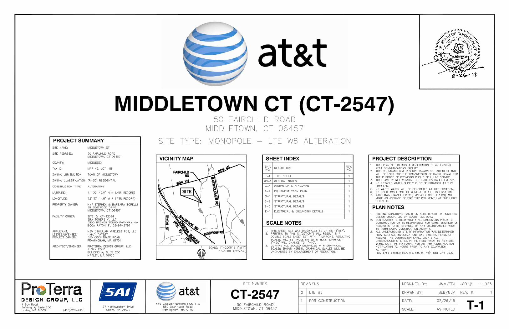
Re: New Cingular Wireless PCS, LLC notice of intent to modify an existingtelecommunications facility located at 50 Fairchild Road, Middletown,Connecticut.
Dear Ms. Bachman:
In order to accommodate technological changes, implement Uniform MobileTelecommunications System (“UMTS”) and/or Long Term Evolution (“LTE”) capabilities,and enhance system performance in the State of Connecticut, New Cingular Wireless PCS,LLC (“AT&T”) plans to modify the equipment configurations at many of its existing cell sites.Please accept this letter and attachments as notification, pursuant to R.C.S.A. Section 16-50j-73, of construction which constitutes an exempt modification pursuant to R.C.S.A. Section 16-50j-72(b)(2). In compliance with R.C.S.A. Section 16-50j-73, copies of this letter are beingsent to the chief elected official of the municipality in which the affected cell site is located, theproperty owner of record, and the tower owner or operator.
UMTS technology offers services to mobile computer and phone users anywhere in the world.Based on the Global System for Mobile (“GSM”) communication standard, UMTS is theplanned worldwide standard for mobile users. UMTS, fully implemented, gives computer andphone users high-speed access to the Internet as they travel. They have the same capabilitieseven when they roam, through both terrestrial wireless and satellite transmissions.
LTE is a high-performance air interface for cellular mobile communications. It is designed toincrease the capacity and speed of mobile telephone networks.
Attached is a summary of the planned modifications, including power density calculationsreflecting the change in AT&T’s operations at the site. Also included is documentation of thestructural sufficiency of the tower to accommodate the revised antenna configuration.

Page 2
The changes to the facility do not constitute modifications as defined in Connecticut GeneralStatutes (“C.G.S.”) Section 16-50i(d) because the general physical and environmentalcharacteristics of the site will not be significantly changed or altered. Rather, the plannedchanges to the facility fall squarely within those activities explicitly provided for in R.C.S.A.Section 16-50j-72(b)(2).
1. The height of the overall structure will not increase.
2. The proposed changes will not extend the site boundaries.
3. The proposed changes will not increase the noise level at the site boundary by sixdecibels or more, or to levels that exceed state and local criteria.
4. The changes will not add radio frequency sending or receiving capability whichincreases the total radio frequency electromagnetic radiation power density measured atthe site boundary to or above the standards adopted by the Federal CommunicationsCommission pursuant to Section 704 of the Telecommunications Act of 1996, asamended, and the State Department of Energy and Environmental Protection, pursuantto Section 22a-162 of the Connecticut General Statutes.
5. The proposed changes will not impair the structural integrity of the facility, asdetermined in a certification provided by a professional engineer licensed inConnecticut.
For the foregoing reasons, AT&T respectfully submits that the proposed changes at thereferenced site constitute exempt modifications under R.C.S.A. Section 16-50j-72(b)(2).
Please feel free to call me at (860) 830-0380 with questions concerning this matter. Thank youfor your consideration.
Sincerely,
Steven L. LevineReal Estate Consultant
cc: Town CEO – Mayor Daniel T. Drew, City of MiddletownLand Owner of Record – Stephen G & Barbara L. BorrelliTower Owner / Operator – SBA (by email)
Attachments

NEW CINGULAR WIRELESS PCS, LLCEquipment Modification
50 Fairchild Road, MiddletownCSC Approvals: Dockets 316 and 316A
Petition 988Exempt Mod 5/14 (Expired)
AT&T Site CT2547
Background Note: In EM-AT&T-083-140423 (acknowledged 5/13/14) New Cingular WirelessPCS, LLC (“AT&T”) gave notice of its intent to install a multi-LTE-frequency upgrade at the site. AT&T submitted the aforesaid Notice ofExempt Modification with tower modification plans that includedstrengthening the monopole with three guy lines. The acknowledgmentexpired 5/13/15 without the upgrade or tower modifications having beenperformed. Thus, the tower is not guyed.
Tower modifications required for a single-LTE-frequency upgrade areincluded herein. These modifications are adequate to support the proposedloading without installation of guy lines.
Tower Owner/Manager: SBA
Land Owner of Record: Stephen G. & Barbara L. Borrelli
Lease Area: The Fairchild Road facility was approved by the Council inDocket 316 and re-approved in Docket 316A after re-opening.Comparison between the attached Docket 316 site plan and thecurrent design drawings demonstrates that the neither thefenced compound nor the overall lease area will be enlargeddue to the proposed equipment modifications.
Equipment Configuration: Monopole
Current and/or approved: Low profile platform @ 130 ft.Nine PowerWave P65-16-XLH-RR antennas @ 130 ft c.l.Six PowerWave TMA’s @ 130 ftSix remote radio heads @130 ftTwelve runs 1 5/8 inch coaxEquipment shelter

Planned Modifications: Remove existing platform and all antennas, TMA’s, and associatedequipment from the 130 ft level.
Remove six 1 5/8 inch coax lines -- Six to remain.Install recommended structural modifications.Install one Commscope MTC3607R antenna platform with handrails
@ the 130 ft level.Reinstall three PowerWave P65-16-XLH-RR antennas @ 130 ft c.l.Install six CCI OPA-65R-LCUU-XLH-RR antennas @ 130 ft c.l.Install three CCI TMA’s @ 130 ft.Install nine remote radio heads @ 130 ft.Install two Raycap DC6-48-60-18-8F surge arrestors @ 130 ft.Install two fiber cable and four DC control cables.Install new ice bridge at grade.
Power Density:
Calculations for AT&T’s current operations at the site indicate a radio frequencyelectromagnetic radiation power density, measured at the monopole base, of approximately 44.4 %of the standard adopted by the FCC. As depicted in the second table below, the total radio frequencyelectromagnetic radiation power density for AT&T’s planned operations would be approximately43.3 % of the standard.
Existing
CompanyCenterline Ht
(feet) Frequency
(MHz)Number ofChannels
Power PerChannel(Watts)
Power Density
(mW/cm2)
StandardLimits
(mW/cm2)
Percent ofLimit
Other Users * 35.24AT&T LTE * 130 740 1 500 0.0106 0.4933 2.16
AT&T UMTS * 130 880 - 894 1 500 0.0106 0.5867 1.81AT&T UMTS * 130 1900 Band 1 500 0.0106 1.0000 1.06AT&T GSM * 130 880 - 894 3 296 0.0189 0.5867 3.22AT&T GSM * 130 1900 Band 1 427 0.0091 1.0000 0.91
Total 44.4%* Per CSC records. (Petition 988)
Proposed
CompanyCenterline Ht
(feet) Frequency
(MHz)Number ofChannels
Power PerChannel(Watts)
Power Density
(mW/cm2)
StandardLimits
(mW/cm2)
Percent ofLimit
Other Users * 35.24AT&T LTE * 130 700 Band 1 500 0.0106 0.4667 2.28
AT&T UMTS * 130 880 - 894 2 500 0.0213 0.5867 3.63AT&T UMTS * 130 1900 Band 2 500 0.0213 1.0000 2.13
Total 43.3%* Per CSC records.

Structural information:
The attached structural analysis demonstrates that the tower and foundation will haveadequate structural capacity to accommodate the proposed equipment modifications uponcompletion of recommended structural modifications described in attachments hereto. (FDHVelocitel, 8-7-15)


Velocitel, Inc., d.b.a. FDH Velocitel, 6521 Meridien Drive Raleigh, NC 27616, Ph. 919.755.1012
Document No. ENG-RPT-501S Revision Date: 06/17/11
Structural Analysis forSBA Network Services, Inc.
130’ Monopole Tower
SBA Site Name: Middletown 2SBA Site ID: CT13064-A-05AT&T Site Name: CT2547
FDH Velocitel Project Number 15BVZK1400 (R1)
Analysis ResultsTower Components 95.5% Sufficient
Foundation 96.1% Sufficient
Prepared By: Reviewed By:
Byron K Webb, EI
Project Engineer
Dennis D. Abel, PEDirector of Structural Engineering
CT PE License No. 23247
Velocitel, Inc., d.b.a FDH Velocitel6521 Meridien DriveRaleigh, NC 27616
(919) [email protected]
August 7, 2015
Prepared pursuant to TIA/EIA-222-F Structural Standards for Steel Antenna Towers and Antenna Supporting Structures and the 2005 Connecticut State Building Code

Structural Analysis ReportSBA Network Services, Inc.SBA Site ID: CT13064-A-05
August 7, 2015
Document No. ENG-RPT-501S Revision Date: 06/17/112
TABLE OF CONTENTS
EXECUTIVE SUMMARY............................................................................................................................................................3
Conclusions............................................................................................................................................................................3
Recommendations .................................................................................................................................................................3
APPURTENANCE LISTING .......................................................................................................................................................4
RESULTS...................................................................................................................................................................................5
GENERAL COMMENTS ............................................................................................................................................................7
LIMITATIONS.............................................................................................................................................................................7
APPENDIX .................................................................................................................................................................................8

Structural Analysis ReportSBA Network Services, Inc.SBA Site ID: CT13064-A-05
August 7, 2015
Document No. ENG-RPT-501S Revision Date: 06/17/113
EXECUTIVE SUMMARY
At the request of SBA Network Services, Inc., FDH Velocitel, Inc. performed a structural analysis of the monopole located inMiddletown, CT to determine whether the tower is structurally adequate to support both the existing and proposed loadspursuant to the Structural Standard for Steel Antenna Towers and Antenna Supporting Structures, TIA/EIA-222-F and 2005Connecticut State Building Code (CSBC). Information pertaining to the existing/proposed antenna loading, current towergeometry, geotechnical data, and member sizes was obtained from:
Radian Communication Services (File No. 060-3494) original design drawings dated December 15, 2006FDH Engineering, Inc. (Project No. 11-01248E S1) Modification & 10’ Extension Drawings for a 120’ Monopole
dated September 21, 2011FDH Engineering, Inc. (Project No. 11-01248E S1) Post Construction Inspection Report dated December 14, 2011FDH Engineering, Inc. (Job No. 12-08192E S2) Modification Drawings for a 130’ Monopole dated November 14,
2012FDH Engineering, Inc. (Project No. 12-11103T C1) TIA Inspection Report dated February 18, 2013FDH Engineering, Inc. (Project No. 12-11103T C1) Modification Inspection Report dated March 13, 2013Gemini Geotechnical Associates, Inc. (Site No. 999-0049) Geotechnical Engineering Report dated November 30,
2006FDH Velocitel (Project No. 15BVXK1400) Modification Drawings for a 130’ Monopole dated August 6, 2015SBA Network Services, Inc.
The basic design wind speed per the TIA/EIA-222-F standards is 90 mph without ice and 38 mph with 3/4” radial ice. Ice isconsidered to increase in thickness with height.
Conclusions
With the existing and proposed antennas from AT&T in place at 130 ft, the tower meets the requirements of the TIA/EIA-222-F standards and 2005 CSBC provide the Recommendations below are satisfied. Further, provided the foundation wasconstructed per the original design drawings (see Radian File No. 060-3494) and utilizing the existing soil parameters (seeGemini Geotechnical Site No. 999-0049), the foundation should have the necessary capacity to support both the proposedand existing loading. For a more detailed description of the analysis of the tower, see the Results section of this report.
Our structural analysis has been performed assuming all information provided to FDH Velocitel, Inc. is accurate (i.e., thesteel data, tower layout, existing antenna loading, and proposed antenna loading) and that the tower has been properlyerected and maintained per the original design drawings.
Recommendations
To ensure the requirements of the TIA/EIA-222-F standards are met with the existing and proposed loading in place, we havethe following recommendations:
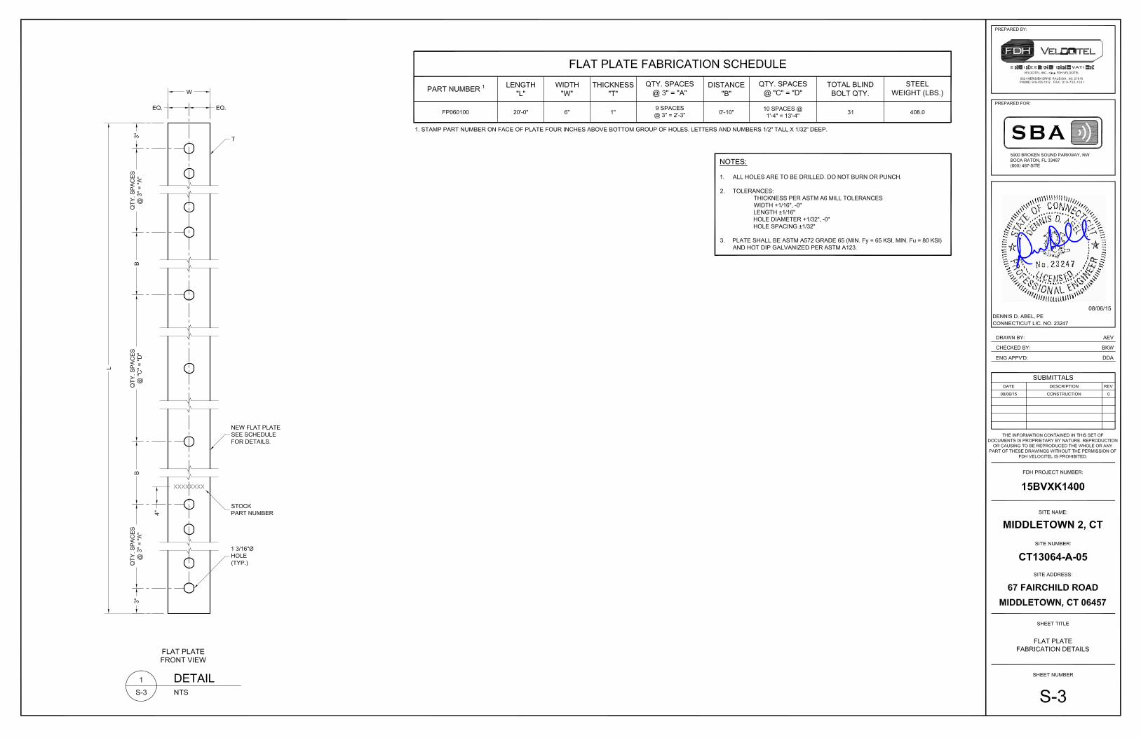
1. The proposed feed lines should be installed inside the pole’s shaft.2. Nextel’s equipment at 120’ must be removed for this analysis to be valid.3. The modifications listed in FDH Velocitel (Project No. 15BVXK1400) Modification Drawings for a 130’ Monopole
dated August 6, 2015 must be installed as specified

Structural Analysis ReportSBA Network Services, Inc.SBA Site ID: CT13064-A-05
August 7, 2015
Document No. ENG-RPT-501S Revision Date: 06/17/114
APPURTENANCE LISTING
The proposed and existing antennas with their corresponding cables/coax lines are shown in Table 1. If the actual layoutdetermined in the field deviates from the layout, FDH Velocitel, Inc. should be contacted to perform a revised analysis.
Table 1 - Appurtenance Loading
Existing Loading:
AntennaElevation
(ft)Description Feed Lines1 Carrier
MountElevation
(ft)Mount Type
130
(9) Powerwave P65-16-XLH-RR(6) Powerwave TT19-08BP111-001
(6) Powerwave 7010(6) Ericsson RRUS-11
(18) 1-5/8” AT&T 129 (1) Low-Profile Platform
1202 (6) RFS APXV86-906515 (12) 1-5/8” Nextel 120 (6) Pipe Mounts
111 (3) Andrew CBC721-DF
(12) 1-5/8”(2) 1-5’8” Hybriflex
Verizon 110 (3) T-Arms110
(6) Andrew SBNHH-1D65B(3) Alcatel-lucent RRH 2x60-1900 4R(3) Alcatel-lucent B13 RRH4x30-4R(3) Alcatel Lucent RRH B4 2x60-4R
(2) RFS DB-T1-6Z-8AB-0Z109 (3) Andrew CBC721-DF
100(3) Ericsson Air 21 B2A/B4P(3) Ericsson Air 21 B4A/B2P
(6) 1-5/8”(1) 1-5/8” Fiber
T-Mobile 100(3) T-Arms
(Site Pro P/N RMV12-3xx)94 (1) 1’4” x 6.5” x 6” Surge Protector
(3) 5/16”(2) 1/2”(3) 5/8”(3) 1/4”
Clearwire
94 Direct Mount
91(3) Kathrein 840 10054
(3) Samsung RASSPI-2213-RRH89.5 (3) T-Arms90.8 (1) Andrew VHLP2-18-DW1
90.7 (1) VHLP800-11-DW11. Feed lines installed inside the pole’s shaft unless otherwise noted.2. Nextel’s equipment at 120’ is to be removed and is not considered in this analysis.
Proposed Carrier Final Loading:
AntennaElevation
(ft)Description Feed Lines Carrier
MountElevation
(ft)Mount Type
130
(6) Cci Antennas OPA-65R-LCUU-H6(3) Powerwave Technologies P65-16-XLH-RR
(3) Ericsson RRUS E2 B29(3) Ericsson RRUS-32(3) Ericsson RRU 11
(3) Cci DTMABP7819VG12A(2) Raycap DC6-48-60-18-8F
(6) 1-5/8”(2) Fiber1
(4) DC1
AT&T 129(1) 12.5’ Platform w/ Handrails(Commscope P/N MTC3607R)
1. Feed lines installed inside (3) 3” flex conduits on the outside of the monopole shaft.
Structural Analysis ReportSBA Network Services, Inc.SBA Site ID: CT13064-A-05
August 7, 2015
Document No. ENG-RPT-501S Revision Date: 06/17/115
RESULTS
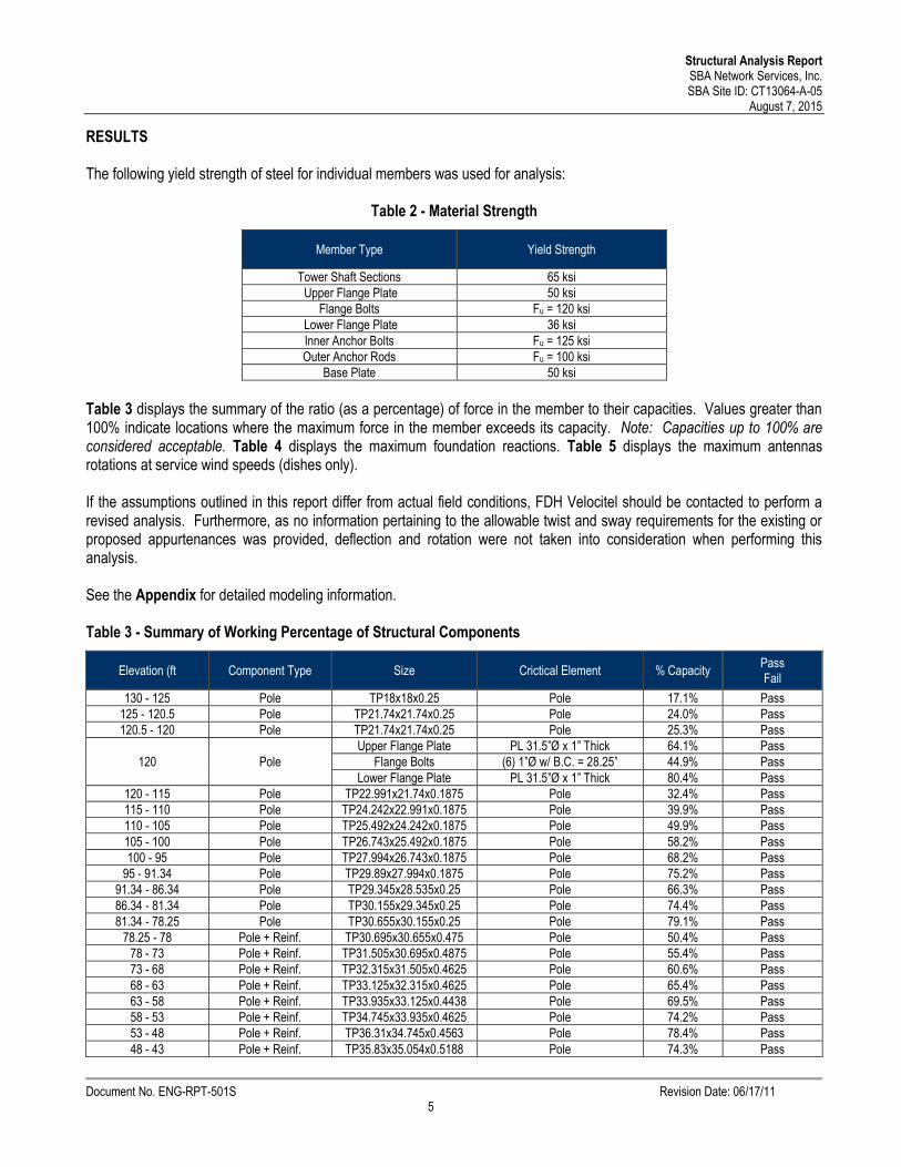
The following yield strength of steel for individual members was used for analysis:
Table 2 - Material Strength
Member Type Yield Strength
Tower Shaft Sections 65 ksiUpper Flange Plate 50 ksi
Flange Bolts Fu = 120 ksiLower Flange Plate 36 ksiInner Anchor Bolts Fu = 125 ksiOuter Anchor Rods Fu = 100 ksi
Base Plate 50 ksi
Table 3 displays the summary of the ratio (as a percentage) of force in the member to their capacities. Values greater than100% indicate locations where the maximum force in the member exceeds its capacity. Note: Capacities up to 100% areconsidered acceptable. Table 4 displays the maximum foundation reactions. Table 5 displays the maximum antennasrotations at service wind speeds (dishes only).
If the assumptions outlined in this report differ from actual field conditions, FDH Velocitel should be contacted to perform arevised analysis. Furthermore, as no information pertaining to the allowable twist and sway requirements for the existing orproposed appurtenances was provided, deflection and rotation were not taken into consideration when performing thisanalysis.
See the Appendix for detailed modeling information.
Table 3 - Summary of Working Percentage of Structural Components
Elevation (ft Component Type Size Crictical Element % CapacityPassFail
130 - 125 Pole TP18x18x0.25 Pole 17.1% Pass125 - 120.5 Pole TP21.74x21.74x0.25 Pole 24.0% Pass120.5 - 120 Pole TP21.74x21.74x0.25 Pole 25.3% Pass
120 PoleUpper Flange Plate PL 31.5”Ø x 1” Thick 64.1% Pass
Flange Bolts (6) 1”Ø w/ B.C. = 28.25” 44.9% PassLower Flange Plate PL 31.5”Ø x 1” Thick 80.4% Pass
120 - 115 Pole TP22.991x21.74x0.1875 Pole 32.4% Pass115 - 110 Pole TP24.242x22.991x0.1875 Pole 39.9% Pass110 - 105 Pole TP25.492x24.242x0.1875 Pole 49.9% Pass105 - 100 Pole TP26.743x25.492x0.1875 Pole 58.2% Pass100 - 95 Pole TP27.994x26.743x0.1875 Pole 68.2% Pass
95 - 91.34 Pole TP29.89x27.994x0.1875 Pole 75.2% Pass91.34 - 86.34 Pole TP29.345x28.535x0.25 Pole 66.3% Pass86.34 - 81.34 Pole TP30.155x29.345x0.25 Pole 74.4% Pass81.34 - 78.25 Pole TP30.655x30.155x0.25 Pole 79.1% Pass
78.25 - 78 Pole + Reinf. TP30.695x30.655x0.475 Pole 50.4% Pass78 - 73 Pole + Reinf. TP31.505x30.695x0.4875 Pole 55.4% Pass73 - 68 Pole + Reinf. TP32.315x31.505x0.4625 Pole 60.6% Pass68 - 63 Pole + Reinf. TP33.125x32.315x0.4625 Pole 65.4% Pass63 - 58 Pole + Reinf. TP33.935x33.125x0.4438 Pole 69.5% Pass58 - 53 Pole + Reinf. TP34.745x33.935x0.4625 Pole 74.2% Pass53 - 48 Pole + Reinf. TP36.31x34.745x0.4563 Pole 78.4% Pass48 - 43 Pole + Reinf. TP35.83x35.054x0.5188 Pole 74.3% Pass

Structural Analysis ReportSBA Network Services, Inc.SBA Site ID: CT13064-A-05
August 7, 2015
Document No. ENG-RPT-501S Revision Date: 06/17/116
Elevation (ft Component Type Size Crictical Element % CapacityPassFail
43 - 38 Pole + Reinf. TP36.605x35.83x0.5125 Pole 77.8% Pass38 - 33 Pole + Reinf. TP37.381x36.605x0.4875 Pole 80.2% Pass33 - 28 Pole + Reinf. TP38.156x37.381x0.4875 Pole 84.2% Pass28 - 23 Pole + Reinf. TP38.932x38.156x0.5 Pole 87.3% Pass23 - 18 Pole + Reinf. TP39.707x38.932x0.5 Pole 90.1% Pass18 - 13 Pole + Reinf. TP40.483x39.707x0.5 Pole 92.2% Pass
13 - 8.08 Pole + Reinf. TP41.247x40.483x0.4875 Pole 95.5% Pass8.08 - 7.83 Pole + Reinf. TP41.285x41.247x0.725 Pole 69.0% Pass7.83 - 2.83 Pole + Reinf. TP42.061x41.285x0.7375 Pole 70.2% Pass
2.83 - 0 Pole + Reinf. TP42.5x42.061x0.7375 Pole 71.4% PassInner Anchor Bolts (14) 1.5"Ø w/ B.C. = 47.25” 60.9% PassOuter Anchor Rods (8) 2.25”Ø w/ B.C. = 56.75” 84.5% Pass
Base Plate PL 51.75"Ø x 1.5" Thick 56.1% Pass
Table 4 - Maximum Base Reactions
Base ReactionsCurrent Analysis*(TIA/EIA-222-F)
Original Design(ANSI/TIA-222-G)
Axial 29 k 39 kShear 26 k 23 k
Moment 2,338 k-ft 1,864 k-ft*Foundations determined to be adequate per independent analysis.
Table 5 – Maximum Antenna Rotations at Service Wind Speeds (Dishes Only)
Centerline Elevation (ft) Antenna Tilt (deg)* Twist (deg)*
90.8 (1) VHLP2-18-DW1 1.1500 0.0022
90.7 (1) VHLP800-11-DW1 1.1488 0.0022
*Allowable tilt and twist values to be reviewed by the carrier.

Structural Analysis ReportSBA Network Services, Inc.SBA Site ID: CT13064-A-05
August 7, 2015
Document No. ENG-RPT-501S Revision Date: 06/17/117
GENERAL COMMENTS
This engineering analysis is based upon the theoretical capacity of the structure. It is not a condition assessment of thetower and its foundation. It is the responsibility of SBA Network Services, Inc. to verify that the tower modeled and analyzedis the correct structure (with accurate antenna loading information) modeled. If there are substantial modifications to bemade or the assumptions made in this analysis are not accurate, FDH Velocitel should be notified immediately to perform arevised analysis.
LIMITATIONS
All opinions and conclusions are considered accurate to a reasonable degree of engineering certainty based upon theevidence available at the time of this report. All opinions and conclusions are subject to revision based upon receipt of newor additional/updated information. All services are provided exercising a level of care and diligence equivalent to thestandard and care of our profession. No other warranty or guarantee, expressed or implied, is offered. Our services areconfidential in nature and we will not release this report to any other party without the client’s consent. The use of thisengineering work is limited to the express purpose for which it was commissioned and it may not be reused, copied, ordistributed for any other purpose without the written consent of FDH Velocitel.

Structural Analysis ReportSBA Network Services, Inc.SBA Site ID: CT13064-A-05
August 7, 2015
Document No. ENG-RPT-501S Revision Date: 06/17/118
APPENDIX

Structural Analysis ReportSBA Network Services, Inc.SBA Site ID: CT13064-A-05
August 7, 2015
Document No. ENG-RPT-501S Revision Date: 06/17/119
Figure 1: Proposed Feed Line Layout

Tower Analyst
FDH Velocitel6521 Merdien Dr
Raleigh, NC 27616Phone: (919) 755-1012FAX: (919) 755-1031
Job:Middletown - CT13064-A
Project: 15BVXK1400Client: SBA Network Services, Inc. Drawn by: Byron K Webb App'd:
Code: TIA/EIA-222-F Date: 08/06/15 Scale: NTSPath:
\\fdh-server\Projects\2015 Effective - Client Jobs\SBANET_SBA Network Services, Inc\CT\CT13064-A - Middletown 2, CT\15BVXK1400-MODMOO_ATT\R.0\Analysis\PassingTower\Mod.eri
Dwg No. E-1
130.0 ft
125.0 ft
120.5 ft
115.0 ft
110.0 ft
105.0 ft
100.0 ft
95.0 ft
87.4 ft
81.3 ft
78.3 ft
73.0 ft
68.0 ft
63.0 ft
58.0 ft
53.0 ft
43.3 ft
38.0 ft
33.0 ft
28.0 ft
23.0 ft
18.0 ft
13.0 ft
8.1 ft
2.8 ft
0.0 ft
REACTIONS - 90 mph WINDTORQUE 1 kip-ft
26 KSHEAR
2338 kip-ftMOMENT
29 KAXIAL
38 mph WIND - 0.7500 in ICETORQUE 0 kip-ft
6 KSHEAR
517 kip-ftMOMENT
40 KAXIAL
Sec
tion
12
34
56
78
910
1112
1314
1516
1718
1920
2122
2324
2526
2728
2930
Leng
th(ft
)5.
004.
500.
505.
005.
005.
005.
005.
007.
585.
005.
003.
090.
255.
005.
005.
005.
005.
009.
665.
005.
005.
005.
005.
005.
005.
004.
920.
255.
002.
83
Num
bero
fSid
es0
00
1818
1818
1818
1818
1818
1818
1818
1818
1818
1818
1818
1818
1818
18
Thic
knes
s(in
)0.
2500
0.25
000.
2500
0.18
750.
1875
0.18
750.
1875
0.18
750.
1875
0.25
000.
2500
0.25
000.
4750
0.48
750.
4625
0.46
250.
4437
0.46
250.
4562
0.51
880.
5125
0.48
750.
4875
0.50
000.
5000
0.50
000.
4875
0.72
500.
7375
0.73
75
Soc
ketL
engt
h(ft
)3.
924.
67
Top
Dia
(in)
18.0
000
21.7
400
21.7
400
21.7
400
22.9
908
24.2
415
25.4
923
26.7
431
27.9
938
28.5
352
29.3
451
30.1
550
30.6
549
30.6
954
31.5
053
32.3
152
33.1
250
33.9
349
34.7
448
35.0
541
35.8
297
36.6
052
37.3
808
38.1
564
38.9
319
39.7
075
40.4
830
41.2
467
41.2
855
42.0
610
Bot
Dia
(in)
18.0
000
21.7
400
21.7
400
22.9
908
24.2
415
25.4
923
26.7
431
27.9
938
29.8
900
29.3
451
30.1
550
30.6
549
30.6
954
31.5
053
32.3
152
33.1
250
33.9
349
34.7
448
36.3
100
35.8
297
36.6
052
37.3
808
38.1
564
38.9
319
39.7
075
40.4
830
41.2
467
41.2
855
42.0
610
42.5
000
Gra
deA
500-
50A
572-
65
Wei
ght(
K)
0.2
0.3
0.0
0.2
0.2
0.2
0.3
0.3
0.4
0.4
0.4
0.3
0.0
0.8
0.8
0.8
0.9
0.9
1.7
1.0
1.0
1.0
1.0
1.0
1.1
1.1
1.1
0.1
1.6
0.9
20.1
Lightning Rod 130P65-16-XLH-RR W/ Mount Pipe 129P65-16-XLH-RR W/ Mount Pipe 129P65-16-XLH-RR W/ Mount Pipe 129(2) OPA-65R-LCUU-H6 w/ Mount Pipe 129(2) OPA-65R-LCUU-H6 w/ Mount Pipe 129(2) OPA-65R-LCUU-H6 w/ Mount Pipe 129DTMABP7819VG12A TMA 129DTMABP7819VG12A TMA 129DTMABP7819VG12A TMA 129RRU-11 129RRU-11 129RRU-11 129RRUS-32 129RRUS-32 129RRUS-32 129RRUS-E2 B29 129RRUS-E2 B29 129RRUS-E2 B29 129DC6-48-60-18-8F 129DC6-48-60-18-8F 129(1) Low-Profile Platform 129BXA-63606380CF w/ Mount Pipe 110BXA-63606380CF w/ Mount Pipe 110CBC721-DF 110CBC721-DF 110CBC721-DF 110CBC721-DF 110CBC721-DF 110CBC721-DF 110SBNH-1D6565B w/ Mount Pipe 110SBNH-1D6565B w/ Mount Pipe 110SBNH-1D6565B w/ Mount Pipe 110RRH2X40-AWS 110RRH2X40-AWS 110RRH2X40-AWS 110DB-T1-6Z-8AB-0Z 110(3) T-Arms 110BXA-63606380CF w/ Mount Pipe 110AIR 21 B2A/B4P w/Mount Pipe 100AIR 21 B2A/B4P w/Mount Pipe 100AIR 21 B2A/B4P w/Mount Pipe 100AIR 21 B4A/B2P w/Mount Pipe 100AIR 21 B4A/B2P w/Mount Pipe 100AIR 21 B4A/B2P w/Mount Pipe 100Site Prol RMV12-3xx 1001'4" x 6.5" x 6" Surge Protector 94840 10054 w/ Mount Pipe 89.5RASSPI-2213-RRH 89.5RASSPI-2213-RRH 89.5RASSPI-2213-RRH 89.5(3) T-Arms 89.5840 10054 w/ Mount Pipe 89.5840 10054 w/ Mount Pipe 89.5VHLP2-18-DW1 89.5VHLP800-11-DW1 89.5DESIGNED APPURTENANCE LOADINGTYPE TYPEELEVATION ELEVATION
Lightning Rod 130P65-16-XLH-RR W/ Mount Pipe 129P65-16-XLH-RR W/ Mount Pipe 129P65-16-XLH-RR W/ Mount Pipe 129(2) OPA-65R-LCUU-H6 w/ Mount Pipe 129(2) OPA-65R-LCUU-H6 w/ Mount Pipe 129(2) OPA-65R-LCUU-H6 w/ Mount Pipe 129DTMABP7819VG12A TMA 129DTMABP7819VG12A TMA 129DTMABP7819VG12A TMA 129RRU-11 129RRU-11 129RRU-11 129RRUS-32 129RRUS-32 129RRUS-32 129RRUS-E2 B29 129RRUS-E2 B29 129RRUS-E2 B29 129DC6-48-60-18-8F 129DC6-48-60-18-8F 129(1) Low-Profile Platform 129BXA-63606380CF w/ Mount Pipe 110BXA-63606380CF w/ Mount Pipe 110CBC721-DF 110CBC721-DF 110CBC721-DF 110CBC721-DF 110
CBC721-DF 110CBC721-DF 110SBNH-1D6565B w/ Mount Pipe 110SBNH-1D6565B w/ Mount Pipe 110SBNH-1D6565B w/ Mount Pipe 110RRH2X40-AWS 110RRH2X40-AWS 110RRH2X40-AWS 110DB-T1-6Z-8AB-0Z 110(3) T-Arms 110BXA-63606380CF w/ Mount Pipe 110AIR 21 B2A/B4P w/Mount Pipe 100AIR 21 B2A/B4P w/Mount Pipe 100AIR 21 B2A/B4P w/Mount Pipe 100AIR 21 B4A/B2P w/Mount Pipe 100AIR 21 B4A/B2P w/Mount Pipe 100AIR 21 B4A/B2P w/Mount Pipe 100Site Prol RMV12-3xx 1001'4" x 6.5" x 6" Surge Protector 94840 10054 w/ Mount Pipe 89.5RASSPI-2213-RRH 89.5RASSPI-2213-RRH 89.5RASSPI-2213-RRH 89.5(3) T-Arms 89.5840 10054 w/ Mount Pipe 89.5840 10054 w/ Mount Pipe 89.5VHLP2-18-DW1 89.5VHLP800-11-DW1 89.5
MATERIAL STRENGTHGRADE GRADEFy FyFu Fu
A500-50 50 ksi 62 ksi A572-65 65 ksi 80 ksi
TOWER DESIGN NOTES1. Tower is located in Middlesex County, Connecticut.2. Tower designed for a 90 mph basic wind in accordance with the TIA/EIA-222-F Standard.3. Tower is also designed for a 38 mph basic wind with 0.75 in ice. Ice is considered to
increase in thickness with height.4. Deflections are based upon a 50 mph wind.5. TOWER RATING: 79.2%


Centek Engineering, Inc.3-2 North Branford RoadBranford, Connecticut 06405Phone: (203) 488-0580Fax: (203) 488-8587
Steven L. LevineReal Estate Consultant
August 19, 2015
Mayor Daniel T. DrewCity of MiddletownMunicipal Bldg., 245 DeKoven DriveMiddletown, CT 06457
Re: New Cingular Wireless PCS, LLC notice of intent to modify an existing tele-communications facility located at 50 Fairchild Road, Middletown (Owner, SBA)
Dear Mayor Drew:
In order to accommodate technological changes, implement Uniform Mobile TelecommunicationsSystem (“UMTS”) and Long Term Evolution (“LTE”) capabilities, and enhance system performancein the State of Connecticut, New Cingular Wireless PCS, LLC (“AT&T”) will be changing itsequipment configuration at certain cell sites.
As required by Regulations of Connecticut State Agencies (“R.C.S.A.”) Section 16-50j-73, theConnecticut Siting Council has been notified of the changes and will review AT&T’s proposal.Please accept this letter as notification under Section 16-50j-73 of construction which constitutes anexempt modification pursuant to R.C.S.A. Section 16-50j-72(b)(2).
The enclosed Notice fully sets forth the AT&T proposal. However, if you have any questions orrequire any further information on the plans for the site or the Siting Council’s procedures, pleasecontact the undersigned at 860-830-0380 or Ms. Melanie Bachman, Acting Executive Director,Connecticut Siting Council at (860) 827-2935.
Sincerely,
Steven L. LevineReal Estate Consultant
Enclosure

Centek Engineering, Inc.3-2 North Branford RoadBranford, Connecticut 06405Phone: (203) 488-0580Fax: (203) 488-8587
Steven L. LevineReal Estate Consultant
August 19, 2015
Stephen G. & Barbara L. Borrelli67 Fairchild RoadMiddletown, CT 06457
Re: New Cingular Wireless PCS, LLC notice of intent to modify an existing tele-communications facility located at 50 Fairchild Road, Middletown (Owner, SBA)
Dear Mr. & Mrs. Borrelli:
In order to accommodate technological changes, implement Uniform Mobile TelecommunicationsSystem (“UMTS”) and Long Term Evolution (“LTE”) capabilities, and enhance system performancein the State of Connecticut, New Cingular Wireless PCS, LLC (“AT&T”) will be changing itsequipment configuration at certain cell sites.
As required by Regulations of Connecticut State Agencies (“R.C.S.A.”) Section 16-50j-73, theConnecticut Siting Council has been notified of the changes and will review AT&T’s proposal.Please accept this letter as notification under Section 16-50j-73 of construction which constitutes anexempt modification pursuant to R.C.S.A. Section 16-50j-72(b)(2).
The enclosed Notice fully sets forth the AT&T proposal. However, if you have any questions orrequire any further information on the plans for the site or the Siting Council’s procedures, pleasecontact the undersigned at 860-830-0380 or Ms. Melanie Bachman, Acting Executive Director,Connecticut Siting Council at (860) 827-2935.
Sincerely,
Steven L. LevineReal Estate Consultant
Enclosure