telecontrol sinaut micro program 4 modem md720 5 · 2015-01-22 · telecontrol server basic, sinaut...
TRANSCRIPT

MODEM MD720
___________________
___________________
___________________
___________________
___________________
___________________
___________________
___________________
___________________
___________________
SIMATIC NET
Industrial Remote Communication - TeleControl MODEM MD720
Operating Instructions
07/2014 C79000-G8976-C349-02
Preface
Application and properties 1
Installation and connecting up
2
Configuration 3
SINAUT MICRO program block libraries
4
Commissioning and operation
5
Diagnostics and upkeep 6
Technical specifications 7
Certification A
Accessories B
Supported AT commands C
Documentation references D

Siemens AG Industry Sector Postfach 48 48 90026 NÜRNBERG GERMANY
C79000-G8976-C349-02 Ⓟ 08/2014 Subject to change
Copyright © Siemens AG 2014. All rights reserved
Legal information Warning notice system
This manual contains notices you have to observe in order to ensure your personal safety, as well as to prevent damage to property. The notices referring to your personal safety are highlighted in the manual by a safety alert symbol, notices referring only to property damage have no safety alert symbol. These notices shown below are graded according to the degree of danger.
DANGER indicates that death or severe personal injury will result if proper precautions are not taken.
WARNING indicates that death or severe personal injury may result if proper precautions are not taken.
CAUTION indicates that minor personal injury can result if proper precautions are not taken.
NOTICE indicates that property damage can result if proper precautions are not taken.
If more than one degree of danger is present, the warning notice representing the highest degree of danger will be used. A notice warning of injury to persons with a safety alert symbol may also include a warning relating to property damage.
Qualified Personnel The product/system described in this documentation may be operated only by personnel qualified for the specific task in accordance with the relevant documentation, in particular its warning notices and safety instructions. Qualified personnel are those who, based on their training and experience, are capable of identifying risks and avoiding potential hazards when working with these products/systems.
Proper use of Siemens products Note the following:
WARNING Siemens products may only be used for the applications described in the catalog and in the relevant technical documentation. If products and components from other manufacturers are used, these must be recommended or approved by Siemens. Proper transport, storage, installation, assembly, commissioning, operation and maintenance are required to ensure that the products operate safely and without any problems. The permissible ambient conditions must be complied with. The information in the relevant documentation must be observed.
Trademarks All names identified by ® are registered trademarks of Siemens AG. The remaining trademarks in this publication may be trademarks whose use by third parties for their own purposes could violate the rights of the owner.
Disclaimer of Liability We have reviewed the contents of this publication to ensure consistency with the hardware and software described. Since variance cannot be precluded entirely, we cannot guarantee full consistency. However, the information in this publication is reviewed regularly and any necessary corrections are included in subsequent editions.

MODEM MD720 Operating Instructions, 07/2014, C79000-G8976-C349-02 3
Preface
Validity of the documentation This manual is valid for the following product:
● MODEM MD720
Hardware product version 1
Firmware version 1.0
Article number: 6NH9720-3AA01-0XX0
Figure 1 MODEM MD720
On the side of the housing, you will see the firmware version and the hardware product version printed as a placeholder "X". If the printed text is, for example, "X 2 3 4", "X" would be the placeholder for hardware product version 1.
Compatibility with predecessor modules The MD720 MODEM is the successor to the SINAUT MD720-3 modem.
The MD720 MODEM is functionally compatible with the predecessor module SINAUT MD720-3.

Preface
MODEM MD720 4 Operating Instructions, 07/2014, C79000-G8976-C349-02
Abbreviations/acronyms and terminology ● MD720
In the remainder of the text, the MODEM MD720 is also simply known as the "MD720".
The short form MD720 is not used for the predecessor module SINAUT MD720-3.
● TCSB
In the remainder of the manual, the "TeleControl Server Basic" (version V3) software is abbreviated to "TCSB".
● Telecontrol server
The TCSB software is installed on a PC connected to the telecontrol network. The PC on which the TCSB software is installed is known as the "telecontrol server".
Use of the MD720 The MD720 is a GPRS/GSM modem for industrial applications.
It is intended for use in SIMATIC S7 stations that are part of a telecontrol or remote maintenance system and for communication with other stations in the network or an OPC server in the master station. Depending on the configuration, the control center can be either TeleControl Server Basic, SINAUT ST7cc, SINAUT ST7sc or SINAUT MICRO SC.
The MD720 supports the following types of communication:
● IP-based communication with the control center using GPRS and the MSC protocol or the MSCsec secure protocol
● SMS messages from or to a mobile telephone
● CSD communication for maintenance and for data connections
Purpose of the manual This manual describes the properties of this device and supports you when installing, and commissioning and operating the device.
New in this issue ● Description of the program block libraries
● Editorial revision
Replaced documentation This manual replaces the manual release 11/2013.

Preface
MODEM MD720 Operating Instructions, 07/2014, C79000-G8976-C349-02 5
Required experience To install, commission and operate the device, you require experience in the following areas:
● Mobile wireless technology
● IP-based communication
● AT commands
Current manual version and further information on the Internet You will find the current version of this documentation and further information (e.g. FAQs) on the Internet pages of Siemens Automation Customer Support under the following entry ID:
22502072 (http://support.automation.siemens.com/WW/view/en/22502072)
Sources of information and other documentation You will find an overview of further reading and references in the Appendix of this manual.
License conditions
Note Open source software
Read the license conditions for open source software carefully before using the product.
You will find the license conditions on the supplied information sheet.
Security information Siemens provides automation and drive products with industrial security functions that support the secure operation of plants or machines. They are an important component in a holistic industrial security concept. With this in mind, our products undergo continuous development. We therefore recommend that you keep yourself informed with respect to our product updates. Please find further information and newsletters on this subject at: http://support.automation.siemens.com.
To ensure the secure operation of a plant or machine it is also necessary to take suitable preventive action (e.g. cell protection concept) and to integrate the automation and drive components into a state-of-the-art holistic industrial security concept for the entire plant or machine. Any third-party products that may be in use must also be taken into account. Please find further information at: http://www.siemens.com/industrialsecurity
SIMATIC NET glossary Explanations of the specialist terms used in this documentation can be found in the SIMATIC NET glossary.
You will find the SIMATIC NET glossary here:

Preface
MODEM MD720 6 Operating Instructions, 07/2014, C79000-G8976-C349-02
● SIMATIC NET Manual Collection
The DVD ships with certain SIMATIC NET products.
● On the Internet under the following entry ID:
50305045 (http://support.automation.siemens.com/WW/view/en/50305045)
Training, Service & Support You will find information on training, service and support in the multilanguage document "DC_support_99.pdf" on the Internet pages of Siemens Automation Customer Support under the following entry ID:
38652101 (http://support.automation.siemens.com/WW/view/en/38652101)

MODEM MD720 Operating Instructions, 07/2014, C79000-G8976-C349-02 7
Table of contents
Preface ................................................................................................................................................... 3
1 Application and properties ..................................................................................................................... 11
1.1 Communications functions ........................................................................................................... 11
1.2 Requirements ............................................................................................................................... 14
1.3 Configuration examples ............................................................................................................... 16
1.4 Connectors, LEDs, operator controls ........................................................................................... 18
2 Installation and connecting up ............................................................................................................... 21
2.1 Important notes on using the device ............................................................................................ 21 2.1.1 Warning overvoltage protection ................................................................................................... 21 2.1.2 Notices on use in hazardous areas.............................................................................................. 21 2.1.3 Notices regarding use in hazardous areas according to ATEX ................................................... 22 2.1.4 Notices regarding use in hazardous areas according to UL HazLoc ........................................... 23
2.2 SIM card ....................................................................................................................................... 24 2.2.1 Inserting the SIM card .................................................................................................................. 24 2.2.2 Changing a SIM card and PIN ..................................................................................................... 25
2.3 Installing the device ..................................................................................................................... 25
2.4 Connecting the X1 interface ......................................................................................................... 26
2.5 Connecting the antenna ............................................................................................................... 28
2.6 Connecting the power supply ....................................................................................................... 29
3 Configuration ........................................................................................................................................ 31
3.1 Configuration of the MD720 ......................................................................................................... 31
3.2 Storage of data............................................................................................................................. 31
4 SINAUT MICRO program block libraries ................................................................................................ 33
4.1 Use of the MSC and MSCsec protocols in control centers .......................................................... 34
4.2 SINAUT MICRO SC ..................................................................................................................... 35 4.2.1 SINAUT MICRO SC block library ................................................................................................. 35 4.2.2 Program block WDC_INIT ............................................................................................................ 36 4.2.3 Program block WDC_INIT_2 ........................................................................................................ 39 4.2.4 Program block WDC_SEND ........................................................................................................ 42 4.2.5 Program block WDC_RECEIVE ................................................................................................... 44 4.2.6 Program block WDC_CONTROL ................................................................................................. 45
4.3 SINAUT MICRO SC SEC ............................................................................................................ 47 4.3.1 SINAUT MICRO SC SEC block library ........................................................................................ 47 4.3.2 Program block WDC_INIT_2 ........................................................................................................ 48 4.3.3 Program block WDC_SEND ........................................................................................................ 51 4.3.4 Program block WDC_RECEIVE ................................................................................................... 53 4.3.5 Program block WDC_CONTROL ................................................................................................. 54
Table of contents
MODEM MD720 8 Operating Instructions, 07/2014, C79000-G8976-C349-02
4.4 Error numbers ............................................................................................................................. 56
5 Commissioning and operation ............................................................................................................... 57
5.1 Commissioning ............................................................................................................................ 57
5.2 Modes .......................................................................................................................................... 58
5.3 Transparent phase, command phase ......................................................................................... 58
5.4 Changing the operating mode ..................................................................................................... 59
5.5 OPC mode................................................................................................................................... 60 5.5.1 Functions in OPC mode .............................................................................................................. 60 5.5.2 Enabling OPC mode ................................................................................................................... 61 5.5.3 PIN in OPC mode ........................................................................................................................ 61 5.5.4 Connection establishment attempts ............................................................................................ 62
5.6 Terminal mode ............................................................................................................................ 62 5.6.1 Functions in terminal mode ......................................................................................................... 62 5.6.2 Activating terminal mode ............................................................................................................. 62 5.6.3 Operation in terminal mode ......................................................................................................... 63 5.6.4 PIN in terminal mode ................................................................................................................... 63 5.6.5 Service PC with terminal program .............................................................................................. 64 5.6.6 Working with AT commands ....................................................................................................... 65 5.6.7 Composite AT commands (initialization strings) ......................................................................... 67
6 Diagnostics and upkeep ........................................................................................................................ 69
6.1 Diagnostics and maintenance functions ..................................................................................... 69
6.2 LEDs ............................................................................................................................................ 70 6.2.1 Meaning of the LEDs in OPC mode ............................................................................................ 70 6.2.2 Meaning of the LEDs in terminal mode ....................................................................................... 71 6.2.3 SIM card not detected or wrong PIN entered.............................................................................. 71
6.3 Functions of the SET button........................................................................................................ 73
6.4 Local service access via the X1 interface ................................................................................... 73
6.5 Establishing a remote service connection ................................................................................... 74
6.6 Reading out settings ................................................................................................................... 75
6.7 Reading out the log ..................................................................................................................... 77
6.8 Updating firmware ....................................................................................................................... 80
6.9 Resetting to factory settings ........................................................................................................ 81
7 Technical specifications ........................................................................................................................ 83
A Certification ........................................................................................................................................... 85
B Accessories .......................................................................................................................................... 89
B.1 Antennas ..................................................................................................................................... 89
B.2 Connecting cable ........................................................................................................................ 90

Table of contents
MODEM MD720 Operating Instructions, 07/2014, C79000-G8976-C349-02 9
C Supported AT commands ...................................................................................................................... 91
C.1 +++: Change from transparent phase to command phase .......................................................... 93
C.2 A/: Repeat last command line ...................................................................................................... 93
C.3 ATA: Answer call .......................................................................................................................... 93
C.4 ATD: Dial and connection establishment ..................................................................................... 94
C.5 ATE: Local echo on/off ................................................................................................................. 94
C.6 ATH: Terminate existing connection ............................................................................................ 94
C.7 ATI: Output identification .............................................................................................................. 95
C.8 ATO: Return from command phase to transparent phase ........................................................... 95
C.9 ATQ: Display result codes on/off ................................................................................................. 95
C.10 ATV: Set result code format ......................................................................................................... 96
C.11 ATX: Set CONNECT result code format and call monitoring ...................................................... 96
C.12 ATZ: Restart and reset to user settings ....................................................................................... 97
C.13 ATS0?: Display of the setting of the S0 register, set as with ATS0=<n> .................................... 97
C.14 ATS0: Configure automatic answering ........................................................................................ 98
C.15 AT\Q: Hardware flow control on/off .............................................................................................. 98
C.16 AT&C: Set the DCD function ........................................................................................................ 98
C.17 AT&D: Set the DTR function ........................................................................................................ 99
C.18 AT&F: Load factory settings ......................................................................................................... 99
C.19 AT&K: Configure local flow control .............................................................................................. 99
C.20 AT&V: Display current configuration .......................................................................................... 100
C.21 AT&W: Save current profile ....................................................................................................... 100
C.22 AT+CBST: Selection of the bearer service type ........................................................................ 100
C.23 AT+CCLK: Clock ........................................................................................................................ 101
C.24 AT+CGDCONT: Specify the PDP context ................................................................................. 102
C.25 AT+CGSN: Query IMEI .............................................................................................................. 103
C.26 AT+CIMI. Query the IMSI........................................................................................................... 103
C.27 AT+CMGD: Delete an SMS message ....................................................................................... 103
C.28 AT+CMGF: Select SMS message format .................................................................................. 104
C.29 AT+CMGL: List SMS messages in preferred storage ............................................................... 104
C.30 AT+CMGR: Read SMS message .............................................................................................. 106
C.31 AT+CMGS: Send SMS message ............................................................................................... 106
C.32 AT+CMGW: Store SMS message ............................................................................................. 107
C.33 AT+CNMI: Display new SMS message ..................................................................................... 108
C.34 AT+CNUM: Subscriber phone number ...................................................................................... 109

Table of contents
MODEM MD720 10 Operating Instructions, 07/2014, C79000-G8976-C349-02
C.35 AT+COPS: Network operator selection .................................................................................... 110
C.36 AT+CPAS: Activity status .......................................................................................................... 111
C.37 AT+CPIN: Enter PIN ................................................................................................................. 112
C.38 AT+CPMS: Preferred SMS storage .......................................................................................... 113
C.39 AT+CPOL: List of preferred network operators ........................................................................ 114
C.40 AT+CRC: Set cellular result codes for incoming calls .............................................................. 114
C.41 AT+CREG: Network registration ............................................................................................... 115
C.42 AT+CRLP: Radio link protocol .................................................................................................. 115
C.43 AT+CSCA: SMSC address ....................................................................................................... 116
C.44 AT+CSMP: Set parameter for SMS text mode ......................................................................... 117
C.45 AT+CSQ: Query the signal quality ............................................................................................ 117
C.46 AT+IPR: Set the transmission speed of the X1 interface.......................................................... 118
D Documentation references ................................................................................................................... 119
D.1 /1/ .............................................................................................................................................. 119
D.2 /2/ .............................................................................................................................................. 119
D.3 /3/ .............................................................................................................................................. 120
Index ................................................................................................................................................... 121
MODEM MD720 Operating Instructions, 07/2014, C79000-G8976-C349-02 11
Application and properties 1 1.1 Communications functions
Communications functions The MD720 supports the following extra functions:
● Modes
The MD720 is set to one of the following two modes depending on the type of communication required:
– OPC mode
– Terminal mode
● OPC mode
In OPC mode, there is productive data exchange with the control center using GPRS.
● Terminal mode
In terminal mode, the MD720 uses CSD communication for the following functions:
– Sending and receiving SMS messages
– Diagnostics and maintenance functions
– Transfer of configuration data
● Communication with a control center
In OPC mode, an MD720 connected to an S7 station communicates with a control center via a TCP connection. For the data transfer, the GSM network is used with the GPRS service. Either the MSC protocol or the MSCsec protocol is used (see below).
● Sending and receiving SMS messages
The locally connected application (SIMATIC) can transfer data for an SMS message to the MD720 using AT commands. The MD720 sends the SMS message to a subscriber in the GSM network (mobile wireless telephone) or when using a gateway, to a remote fax machine.
SMS messages received by the MD720 can be queried by the local application using AT commands.

Application and properties 1.1 Communications functions
MODEM MD720 12 Operating Instructions, 07/2014, C79000-G8976-C349-02
● CSD communication
Service data calls via remote connections in CSD format are used for the following purposes:
– Remote configuration of the MD720
– Diagnostics and maintenance functions using AT commands
– Process data connections between stations with TIM modules
The partner for the remote connection can be an analog modem, an ISDN modem or a GSM modem.
● Controlling the MD720 using AT commands
You can control the MD720 from a locally connected application or manually with a terminal program connected locally.
● MSC protocol
Proprietary protocol used for productive communication via TCP connections in OPC mode. The MSC allows authentication of the communications partner and simple encryption. The MSC protocol is supported by the following control center applications:
– TeleControl Server Basic (TCSB)
– SINAUT MICRO SC
● MSCsec protocol
Proprietary protocol used for productive communication via TCP connections in OPC mode. In addition to the MSC protocol, it also allows authentication of the messages using an HMAC with the help of a symmetrical encryption method (with pre-shared key). The MSCsec protocol is supported by the following control center applications:
– TeleControl Server Basic (TCSB)
SIMATIC S7 systems that can be connected locally The following SIMATIC S7 systems can be connected to the GSM network via the MD720:
● SIMATIC S7- 200 via SINAUT PPI modem cable (6NH9701-0AD)
● SIMATIC S7- 300 via Ethernet TIM module (using GPRS)
● SIMATIC S7- 400 via TIM 4R IE (using GPRS)
● SIMATIC S7-300/400 via classic or Ethernet TIM module (only using CSD)
For project-specific solutions with SIMATIC S7-300, please contact Siemens Automation Customer Support. You will find an example of an application with the corresponding documentation on the following Internet page:
27038105 (http://support.automation.siemens.com/WW/view/en/27038105)

Application and properties 1.2 Requirements
MODEM MD720 Operating Instructions, 07/2014, C79000-G8976-C349-02 13
Possible partners of the MD720 The MD720 can communicate with the following partners.
● Communications partners of the MD720 installed in an S7-200:
– PC with TeleControl Server Basic (TCSB)
– PC with SINAUT MICRO SC
– S7-200 with MD720 (inter-station communication)
The messages are forwarded by TCSB or SINAUT MICRO SC in the master station.
The MD720 operates in OPC mode.
● Communications partners of the MD720 installed in an S7-300/400:
– Station with Ethernet TIM (e.g. central CPU or control system SINAUT ST7cc/ST7sc)
The MD720 operates in OPC mode.
● Communications partners of the MD720 for SMS messages:
– Mobile phone
– Fax machine (when using a gateway)
The MD720 operates in terminal mode.
● Communications partners of the MD720 installed in an S7-200:
– Engineering station with STEP 7-Micro/WIN
(via GSM network, ISDN network, analog dial-up network)
The MD720 operates in terminal mode.
● Communications partners of the MD720 installed in an S7-300/400 with TIM:
– SIMATIC S7-300/400 with TIM module (including classic)
(via GSM network, ISDN network, analog dial-up network)
The MD720 operates in terminal mode.
Connection resources ● Active connections at runtime
At runtime, the MD720 can connect to 1 communications partner.
The connection partner is configured in the program blocks.

Application and properties 1.2 Requirements
MODEM MD720 14 Operating Instructions, 07/2014, C79000-G8976-C349-02
1.2 Requirements
Requirements for the station with MD720 in OPC mode The following requirements must be met to use the MD720 in OPC mode:
● SIM card of a GSM network operator with activated GPRS service
● Availability of a GSM network
Requirements for the partner in OPC mode ● Fixed IP address or dynamically assigned IP address
To allow the MD720 to establish a connection actively, the partner must have a fixed IP address or a dynamically assigned IP address.
A fixed IP address can be obtained in the following ways:
– Fixed IP address with dedicated line to the GSM network operator
The partner is connected directly to the GSM network operator over a leased dedicated line. In this case, the network operator then normally assigns a fixed IP address.
– Fixed IP address of the Internet service provider
The partner is available over the Internet and a fixed IP address has been assigned to it by the Internet service provider. This can be applied for with some providers.
Many Internet service providers, however, assign the IP addresses dynamically; in other words, the IP addresses of the computers or networks with access to the Internet change (dynamic DNS).
● Internet connection via DSL router
Requirements for the station with MD720 in terminal mode The following requirements must be met to use the MD720 in terminal mode:
● SIM card of a GSM network provider with activated CSD data service 9600 bps
● Extra call number for data calls
● Availability of a GSM network

Application and properties 1.2 Requirements
MODEM MD720 Operating Instructions, 07/2014, C79000-G8976-C349-02 15
Requirements for the partner in terminal mode ● Partner is an engineering station with STEP 7-Micro/WIN
Network attachment of the PC of the engineering station alternatively via:
– MODEM MD720 (communication via GSM network)
– Modem MD3 (communication via analog dial-up network)
– MODEM MD4 (communication via ISDN network)
Note: The MD4 modem is no longer available.
● Partner is SIMATIC S7-300/400 with TIM module (including classic)
Network attachment of the S7 station alternatively via:
– MODEM MD720 (communication via GSM network)
– Modem MD3 (communication via analog dial-up network)
– MODEM MD4 (communication via ISDN network)
Note: The MD4 modem is no longer available.

Application and properties 1.3 Configuration examples
MODEM MD720 16 Operating Instructions, 07/2014, C79000-G8976-C349-02
1.3 Configuration examples
Communication between S7-200 with MD720 and control center The following example shows a configuration in which an S7-200 is connected to the master station with an OPC server via the MD720 MODEM. The OPC server can be TeleControl Server Basic or SINAUT MICRO SC. Communication is via the GSM network with GPRS and via the Internet.
Figure 1-1 Example of a configuration for MODEM MD720 in S7-200

Application and properties 1.3 Configuration examples
MODEM MD720 Operating Instructions, 07/2014, C79000-G8976-C349-02 17
Communication between S7-300 with MD720 and control center The following example shows a configuration in which an S7-300 is connected to the master station via a TIM module and the MD720 MODEM. Communication is via the GSM network with GPRS and via the Internet.
Figure 1-2 Example of a configuration for MODEM MD720 in S7-300

Application and properties 1.4 Connectors, LEDs, operator controls
MODEM MD720 18 Operating Instructions, 07/2014, C79000-G8976-C349-02
1.4 Connectors, LEDs, operator controls
Connectors, display and operator control elements
Front of the device Rear of the device
1 X3: Connector for the 24 VDC power supply (underside of the device) 2 X2: SMA socket for connecting the antenna 3 LEDs 4 SET button 5 X1: Serial interface (RS-232) for connection of the local application (SIMATIC) or the
service PC 6, 9 Holder for DIN rail/switching panel mounting 7 SIM card compartment with slide for the SIM card 8 Button for ejecting the SIM card slide
Meaning of the LEDs The MD720 has three LEDs that are used to indicate the device status. The meaning of the displays is different in terminal and OPC mode. You will find the description in the following sections:
● LEDs in terminal mode: Section Meaning of the LEDs in terminal mode (Page 71)
● LEDs in OPC mode: Section Meaning of the LEDs in OPC mode (Page 70)

Application and properties 1.4 Connectors, LEDs, operator controls
MODEM MD720 Operating Instructions, 07/2014, C79000-G8976-C349-02 19
Connectors ● Power supply (X3)
On the underside of the device, there is a terminal block for connecting the 24 VDC power supply.
● Serial interface (X1)
The X1 interface is a serial interface complying with the RS-232 standard and is used to connect the local application or the service PC.
The interface is designed as a socket. A suitable gender changer is supplied.
● Antenna connector (X2)
The antenna connector is used to connect an external antenna for indoor use in buildings.
You will find detailed information about the connectors in the section Installation and connecting up (Page 21) and the section Technical specifications (Page 83).
SET button The SET button is used to output the current settings on the X1 interface and to reset to the factory settings. You will find details in the section Functions of the SET button (Page 73).

Application and properties 1.4 Connectors, LEDs, operator controls
MODEM MD720 20 Operating Instructions, 07/2014, C79000-G8976-C349-02

MODEM MD720 Operating Instructions, 07/2014, C79000-G8976-C349-02 21
Installation and connecting up 2
Safety notices on the use of the device Note the following safety notices when setting up and operating the device and during all associated work such as installation, connecting up or replacing the device.
2.1 Important notes on using the device
2.1.1 Warning overvoltage protection
Overvoltage protection
NOTICE
Protection of the external power supply
If power is supplied to the module or station over longer power cables or networks, the coupling in of strong electromagnetic pulses onto the power supply cables is possible. This can be caused, for example by lightning strikes or switching of higher loads.
The connector of the external power supply is not protected from strong electromagnetic pulses. To protect it, an external overvoltage protection module is necessary. The manufacturers of industrial overvoltage protection devices produce suitable modules.
2.1.2 Notices on use in hazardous areas
WARNING
EXPLOSION HAZARD
DO NOT OPEN WHEN ENERGIZED.

Installation and connecting up 2.1 Important notes on using the device
MODEM MD720 22 Operating Instructions, 07/2014, C79000-G8976-C349-02
WARNING
The equipment is designed for operation with Safety Extra-Low Voltage (SELV) by a Limited Power Source (LPS).
This means that only SELV / LPS complying with IEC 60950-1 / EN 60950-1 / VDE 0805-1 must be connected to the power supply terminals. The power supply unit for the equipment power supply must comply with NEC Class 2, as described by the National Electrical Code (r) (ANSI / NFPA 70).
If the equipment is connected to a redundant power supply (two separate power supplies), both must meet these requirements.
WARNING
EXPLOSION HAZARD
DO NOT CONNECT OR DISCONNECT EQUIPMENT WHEN A FLAMMABLE OR COMBUSTIBLE ATMOSPHERE IS PRESENT.
WARNING
EXPLOSION HAZARD
SUBSTITUTION OF COMPONENTS MAY IMPAIR SUITABILITY FOR CLASS I, DIVISION 2 OR ZONE 2.
WARNING
When used in hazardous environments corresponding to Class I, Division 2 or Class I, Zone 2, the device must be installed in a cabinet or a suitable enclosure.
2.1.3 Notices regarding use in hazardous areas according to ATEX
WARNING
Requirements for the cabinet/enclosure
To comply with EU Directive 94/9 (ATEX95), this enclosure must meet the requirements of at least IP54 in compliance with EN 60529.

Installation and connecting up 2.1 Important notes on using the device
MODEM MD720 Operating Instructions, 07/2014, C79000-G8976-C349-02 23
WARNING
If the cable or conduit entry point exceeds 70 °C or the branching point of conductors exceeds 80 °C, special precautions must be taken. If the equipment is operated in an air ambient in excess of 50 °C, only use cables with admitted maximum operating temperature of at least 80 °C.
WARNING
Take measures to prevent transient voltage surges of more than 40% of the rated voltage. This is the case if you only operate devices with SELV (safety extra-low voltage).
2.1.4 Notices regarding use in hazardous areas according to UL HazLoc
WARNING
EXPLOSION HAZARD
DO NOT DISCONNECT WHILE CIRCUIT IS LIVE UNLESS AREA IS KNOWN TO BE NON-HAZARDOUS.
This equipment is suitable for use in Class I, Division 2, Groups A, B, C and D or non-hazardous locations only.
This equipment is suitable for use in Class I, Zone 2, Group IIC or non-hazardous locations only.

Installation and connecting up 2.2 SIM card
MODEM MD720 24 Operating Instructions, 07/2014, C79000-G8976-C349-02
2.2 SIM card
2.2.1 Inserting the SIM card
NOTICE
Static charges
Static charges can damage the device. To protect the MD720, take the following precautionary measures before inserting/changing the SIM card or attaching/removing connectors: • Disconnect the device from the power supply. • Discharge any electrical charge from your body.
You can do this by touching an grounded surface, for example an unvarnished part of the cabinet housing.
SIM card Insert the SIM card in the device before you install it.
Use a mini SIM card 15 x 25 mm.
Inserting the SIM card To insert the SIM card, follow the steps below:
1. Turn off the power supply to the station.
2. Remove the MD720 from the DIN rail.
3. Release the slide for the SIM card on the back of the MD720 by gently pressing the release button.
Refer to numbers (7) and (8) in the picture of the rear of the device in the section Connectors, LEDs, operator controls (Page 18).
4. Remove the slide from the housing.
5. Insert the SIM card in the slide.
6. Push the slide back into the housing, where it locks gently in place.

Installation and connecting up 2.3 Installing the device
MODEM MD720 Operating Instructions, 07/2014, C79000-G8976-C349-02 25
2.2.2 Changing a SIM card and PIN
Changing the SIM card and the PIN If you change the SIM card, remember to change the PIN in the program blocks to the PIN of the new SIM card.
If you use a lot of SIM cards it can be helpful to set all PINs to the same PIN number for example using a normal mobile phone. You should, however keep to your company's security regulations relating to SIM cards.
PIN-less SIM cards The device also operates with SIM cards for which the PIN query has been deactivated. In this case, the PIN query is skipped during connection establishment.
2.3 Installing the device
DIN rail mounting, switching panel installation The MD720 can be mounted on a DIN rail (35 mm) complying with EN 60715 in a cabinet or on a switching panel.
Use the pull-out DIN rail mounting clips on the rear if the device to secure it to the rail. These mounting clips also lock into place when they are extended to allow the device to be installed in a switching panel.
The inner dimension of the hole for the DIN rail mounting clips is 4.3 mm.
Installation location
NOTICE
Installation location
During installation, make sure that the upper and lower ventilation slits of the module are not obstructed and good ventilation is possible. Above and below the device, there must be a clearance of 25 mm to allow air to circulate and prevent overheating.
Remember that the permitted temperature ranges depend on the position of the installed device.
Permitted temperature ranges:
● Horizontal installation of the rack (device vertical): -20 °C to 60 °C
● Vertical installation of the rack (device horizontal): -20 °C to 50 °C

Installation and connecting up 2.4 Connecting the X1 interface
MODEM MD720 26 Operating Instructions, 07/2014, C79000-G8976-C349-02
2.4 Connecting the X1 interface
Use of the serial X1 interface The MD720 is connected to the local application via the serial X1 interface (RS-232). The following two alternatives can be used.
● Connection to a SIMATIC station
Connection to a SIMATIC controller is intended for the productive data transfer between the SIMATIC station and the control center.
You will find the connection options of the various SIMATIC families in the section Communications functions (Page 11).
● Connection to service PC
Connection to a service PC is intended for service purposes.
For information on the functions, refer to the section Diagnostics and upkeep (Page 69).
Cable for connecting the X1 interface of the MD720 Different cables are required depending on the connected application:
● SIMATIC S7-200
PPI modem cable 6NH9701-0AD
● Service PC or TIM module
Connecting cable 6NH7701-5AN
Connect the PC via its serial interface COM interface.
If your application has a different interface, a commercially available interface converter can be used.
The connecting cable does not ship with the MD720.
Pinout of the X1 interface (socket) of the MD720 RS-232 signals (signal direction DCE) Pin 1 Output DCD Pin 2 Output RxD Pin 3 Input TxD Pin 4 Input DTR Pin 5 Signal ground GND Pin 6 Output DSR Pin 7 Input RTS Pin 8 Output CTS Pin 9 Output RI

Installation and connecting up 2.4 Connecting the X1 interface
MODEM MD720 Operating Instructions, 07/2014, C79000-G8976-C349-02 27
Pin assignment of the connecting cables ● Pin assignment of PPI modem cable 6NH9701-0AD
● Pin assignment of the connecting cable 6NH7701-5AN
9-pin D-sub female connector to the application
9-pin D-sub male connector to the MD720
The "RI" wire is optional.
Settings for the PPI modem cable 6NH9701-0AD When connecting the MD720 to a SIMATIC S7-200 via the PPI modem cable 6NH9701-0AD, you will need to make the following settings for the PPI adapter in STEP 7-Micro/WIN:
● Character format: 8N1
● Number: 10 bits
● Transmission speed: 57600 bps
● DIP switch: Set the DIP switch according to the following table.
Switch number 1 2 3 4 5 6 7 8 Position 1 1 1 0 0 1 1 0
You will find more information on the PPI modem cable on the Internet pages of Siemens Automation Customer Support under the following entry ID:
34832642 (http://support.automation.siemens.com/WW/view/en/34832642)

Installation and connecting up 2.5 Connecting the antenna
MODEM MD720 28 Operating Instructions, 07/2014, C79000-G8976-C349-02
2.5 Connecting the antenna
CAUTION
RF exposure
The emission limits as recommended by the Commission on Radiological Protection of September 13/14 2001 must be kept to.
When servicing the antenna, or working at distances closer than those listed below, make sure that the transmitter has been disabled.
The antennas used with this mobile device must be at a distance of at least 25 cm from all persons. The antanna must not be positioned or used so that it operates in conjunction with any other antenna or transmitter.
The antennas from the range of Siemens SINAUT/telecontrol accessories operate with 0 dB gain in all directions when connected to the transmitter of the MD720. Using this antenna, the total composite power in PCS mode (1900 MHz) is less than 1 W ERP.
NOTICE
Installation only within buildings
Mount the antenna only within a building.
The MD720 has not been approved for connection of antennas outdoors.
NOTICE
Antenna type
Only use antennas from the range of Siemens SINAUT/telecontrol accessories intended for the MD720 (refer to the appendix of this manual). Other antennas may have detrimental effects on the device characteristics and may even cause damage.
The impedance of the antenna including cable should be approximately 50 ohms.
Connecting the antenna At the top front of the MD720, there is an SMA socket (X2 interface). Connect the antenna there.
Protect the antenna connector using suitable overvoltage protection equipment if the antenna cable is longer than 30 m.
If you install several modem close to each other, keep to a minimum clearance of 50 cm between the antennas.

Installation and connecting up 2.6 Connecting the power supply
MODEM MD720 Operating Instructions, 07/2014, C79000-G8976-C349-02 29
2.6 Connecting the power supply For information on connecting the supply voltage, refer to the section Important notes on using the device (Page 21).
NOTICE
Attachment to battery or rechargeable battery
When connecting the MD720 to a battery or rechargeable battery, include an all-pole disconnect switch (main battery switch) with adequate breaking capacity (at least 3 A at 32 V) and a fuse between the MD720 and battery.
Connecting the power supply The terminal block for the 24 VDC power supply is located on the underside of the device (X3 interface).
You will find the permitted voltage values in the section Technical specifications (Page 83).
● The two screw terminals at the back "L+" (24 V) are interconnected.
● The two front screw terminals "M" (0 V) are interconnected.
Connect the power supply to the terminals of the X3 interface.
Startup The MD720 starts up automatically as soon as it is supplied with power.
Device replacement If you replace an older SINAUT MD720-3 modem with the MD720 MODEM, replace the connector with the screw terminals since this is different on these two devices.

Installation and connecting up 2.6 Connecting the power supply
MODEM MD720 30 Operating Instructions, 07/2014, C79000-G8976-C349-02

MODEM MD720 Operating Instructions, 07/2014, C79000-G8976-C349-02 31
Configuration 3 3.1 Configuration of the MD720
Automatic configuration of the MD720 in OPC mode In OPC mode, the MD720 is configured automatically for GPRS communication by the program blocks called on the connected S7-200 CPU.
As soon as the MD720 is supplied with power and the program blocks on the connected CPU are called, the MD720 establishes a permanent TCP connection to the communications partner.
For more information on the functions of the program blocks, refer to the section SINAUT MICRO program block libraries (Page 33).
You will find information about operating the MD720 in OPC mode in the section OPC mode (Page 60).
Controlling the MD720 in terminal mode In terminal mode the MD720 operates as a GSM modem that is controlled by AT commands.
You will find information about operating the MD720 in terminal mode in the section Terminal mode (Page 62).
3.2 Storage of data All configured data is stored in non-volatile memory on the MD720. After restarting the device or following a power down, the MD720 runs with the last settings to be used.
Only exception: A PIN transferred to the MD720 in terminal mode is not stored permanently on the MD720.

Configuration 3.2 Storage of data
MODEM MD720 32 Operating Instructions, 07/2014, C79000-G8976-C349-02

MODEM MD720 Operating Instructions, 07/2014, C79000-G8976-C349-02 33
SINAUT MICRO program block libraries 4
Block libraries The program blocks for GPRS communication are called on the S7-200 CPU to which the MD720 is connected. Using the blocks, the S7-200 can communicate with other S7 stations or with an OPC server TCSB or SINAUT MICRO SC.
Depending on whether the MSC or MSCsec protocol is used for GPRS transfer, one of the following block libraries is used:
● Using the MSC protocol
Using the program block libraries:
– SINAUT MICRO SC V2.0
File name: sinautmicrosc.mwl
Using the MSCsec protocol
Using the program block library:
– SINAUT MICRO SC SEC V2.0
File name: sinautmicrosc_sec.mwl
Note
Compared with the SINAUT MICRO SC library, the SINAUT MICRO SC SEC library provides greater security with encrypted transmission.
You will find the description of the individual parameters of the program blocks sinautmicrosc.mwl and sinautmicrosc_sec.mwl in the following sections.
You will find information on the SINAUT MICRO SC S7- 200 program blocks and a link to the current version of the block library on the Internet pages of Siemens Automation Customer Support under the following entry ID:
22502072 (http://support.automation.siemens.com/WW/view/en/22502072)
New functions as of version V2.0 The new program blocks as of version V2.0 provide the following new functions:
● The checksum function (as of TCSB version V3) provides greater data consistency.
● With the initialization block INIT_2, you can, for example, initialize the modem without restarting the CPU.

SINAUT MICRO program block libraries 4.1 Use of the MSC and MSCsec protocols in control centers
MODEM MD720 34 Operating Instructions, 07/2014, C79000-G8976-C349-02
Compatibility and memory requirements of the program blocks
Note
Note the differing memory requirements of the various versions of the program block libraries.
Library Compatible with modem... Memory requirements
SINAUT MD720-3
MODEM MD720
With WDC_INIT With WDC_INIT_2
SINAUT MICRO SC V1.16 x - 5835 bytes - SINAUT MICRO SC V2.0 x x 6566 bytes 6571 bytes SINAUT MICRO SC SEC V2.0
- x - 6529 bytes
You should also note the compatibility of the protocols and block libraries with the various OPC server versions.
4.1 Use of the MSC and MSCsec protocols in control centers
Support of the transfer protocols MSC and MSCsec The two protocols are supported by the following control center applications:
● MSC
Is supported by:
– TeleControl Server Basic
– TeleControl Server Basic as of version V3
– SINAUT MICRO SC
● MSCsec
Is supported by:
– TeleControl Server Basic as of version V3

SINAUT MICRO program block libraries 4.2 SINAUT MICRO SC
MODEM MD720 Operating Instructions, 07/2014, C79000-G8976-C349-02 35
4.2 SINAUT MICRO SC
4.2.1 SINAUT MICRO SC block library For wireless communication using GPRS, the S7-200 controller is connected to a GSM/GPRS modem. The modem is configured and controlled by the program blocks of the S7-200. The PLC library SINAUT MICRO SC provides the option of communicating with OPC servers SINAUT MICRO SC / TCSB (TELECONTROL SERVER BASIC version V2) and with other controllers using GPRS.
Block library SINAUT MICRO SC
The program blocks can be executed on the S7-200 CPUs 224, 224XP and 226.
The block library always uses interface 0 of the PLC.
Blocks The block library provides the following blocks for handling GPRS communication:
● WDC_INIT
Initialization of the communication using the program blocks
● WDC_INIT_2
Initialization of the communication using program blocks - with an additional re-initialization input
● WDC_SEND
Handling send jobs
● WDC_RECEIVE:
Processing of received data
● WDC_CONTROL
Control of the communication mode (terminal or OPC mode)
● WDC_CHECKSUM
The WDC_CHECKSUM block is not a user block but must exist in the user program. It is called by the WDC_SEND block.
Comparison of the checksum of a sent and received message. If there are different checksums between the sender and recipient, there has been a transmission error. In this case, a message sent by the modem is discarded by TCSB.

SINAUT MICRO program block libraries 4.2 SINAUT MICRO SC
MODEM MD720 36 Operating Instructions, 07/2014, C79000-G8976-C349-02
4.2.2 Program block WDC_INIT
Significance and how it works The block initializes the block library, the serial interface of the PLC and the GPRS modem.
To reduce the memory requirements of the CPU, link either the WDC_INIT or the WDC_INIT_2 block into the program.
The block must be called twice per cycle by the user program.
Specifying parameters as a string
Many of the parameters must be specified as a string. These strings must be defined in the data block of MicroWIN.
The first byte of the string contains the number of characters, the bytes that follow contain the individual characters. The parameters are transferred to the block by specifying the reference to the relevant string (& operator and memory address of the string).
Example:
Name of the modem at the address VB730.
Data block:
VB730 6 VB731 m VB731 o VB731 d VB731 e VB731 m VB731 1
Calling WDC_INIT

SINAUT MICRO program block libraries 4.2 SINAUT MICRO SC
MODEM MD720 Operating Instructions, 07/2014, C79000-G8976-C349-02 37
Explanation of the formal parameters The following table explains the formal parameters:
Parameter Declaration Data type Value / meaning Description EN INPUT BOOL 0: Block execution blocked
1: Block execution enabled
Enable input for block execution
IP_ADDRESS_CS INPUT DWORD IP address or host name of the server (communications partner). Entry as string.
DESTPORT_CS INPUT DWORD TCP/IP port of the server. Entry as string. MODEM_NAME INPUT DWORD Name for logging on the GPRS modem
with the server. Entry as string. Max. length: 255 characters. * The name should be structured as follows otherwise no connection to TCSB and Micro SC is possible: <modem>+consecutive number Example: Modem_Name VB730 = modem5 Note on TCSB: The automatically assigned consecutive number of the block parameter "MODEM_NAME" is configured in TCSB as the station number of the connection. In TCSB, enter the MODEM_NAME configured here as the station name. Keep to the permitted TCSB syntax.
MODEM_PASSWORD INPUT DWORD Password for logging on the GPRS modem with the server. Entry as string. Max. length: 255 characters. * Note on TCSB: Keep to the permitted TCSB syntax.
PIN INPUT DWORD PIN for enabling the SIM card. Entry as string.
APN INPUT DWORD APN name of the GSM network provider (APN - Access Point Name). Entry as string.
AP_USER INPUT DWORD User name for logging on with the APN. Entry as string.
AP_PASSWORD INPUT DWORD Password for logging in with the APN. Entry as string.
DNS INPUT DWORD IP addresses of 1 or 2 domain name servers of the GSM network provider. Entry as string. If two DNS servers are specified, these are separated by a semicolon, for example "192.168.1.1;192.168.1.2".

SINAUT MICRO program block libraries 4.2 SINAUT MICRO SC
MODEM MD720 38 Operating Instructions, 07/2014, C79000-G8976-C349-02
Parameter Declaration Data type Value / meaning Description CLIP INPUT DWORD List of the phone numbers authorized for
dialing in to the station and for transfer of SMS messages. Only partners with an unauthorized phone number have access to the MD720. 6 numbers must be assigned in the following order: • 3 numbers for service data
connections
Enter at least one phone number if you want to access the station via a remote connection for example to change the configuration or to transfer new software.
• 3 numbers for data connections Entry as a string, individual entries separated by a semicolon (;). Example: +4912345*;NONE;NONE;+49123123;NONE;NONE Enter NONE for empty entries. Enter * (asterisk) as the placeholder for phone number groups. +4912345* for example authorizes all phone numbers that begin with +4912345.
BUSY OUTPUT BOOL 0: Block execution not yet started, completed or aborted 1: Block currently executing
Condition code of the execution status of the block
DONE OUTPUT BOOL 0: Error in block execution. See ERROR. 1: Block executed error-free.
Indicates whether the block executed without errors.
ABORTED OUTPUT BOOL 1: Block execution aborted due to an error
Shows the block execution abort.
ERROR OUTPUT WORD Error code. For the meaning of the value, refer to the section Error numbers (Page 56).
* When using the maximum length of MODEM_NAME and MODEM_PASSWORD, make sure that the memory areas do not overlap.
If, for example, you specify "VB730" as the memory address of the string for MODEM_NAME and "VB740" for MODEM_PASSWORD, you only have 10 bytes for MODEM_NAME: 9 characters + 1 byte length information.

SINAUT MICRO program block libraries 4.2 SINAUT MICRO SC
MODEM MD720 Operating Instructions, 07/2014, C79000-G8976-C349-02 39
4.2.3 Program block WDC_INIT_2
Significance and how it works The block initializes the block library, the serial interface of the PLC and the GPRS modem. Compared with the WDC_INIT block, it also has the additional re-initialization input INIT_START.
To reduce the memory requirements of the CPU, link either the WDC_INIT or the WDC_INIT_2 block into the program.
The block must be called twice per cycle by the user program.
Specifying parameters as a string
Many of the parameters must be specified as a string. These strings must be defined in the data block of MicroWIN.
The first byte of the string contains the number of characters, the bytes that follow contain the individual characters. The parameters are transferred to the block by specifying the reference to the relevant string (& operator and memory address of the string).
Example:
Name of the modem at the address VB730.
Data block:
VB730 6 VB731 m VB731 o VB731 d VB731 e VB731 m VB731 1
Calling WDC_INIT_2

SINAUT MICRO program block libraries 4.2 SINAUT MICRO SC
MODEM MD720 40 Operating Instructions, 07/2014, C79000-G8976-C349-02
Explanation of the formal parameters The following table explains the formal parameters:
Parameter Declaration Data type Range of values /
meaning Description
EN INPUT BOOL 0: Block execution blocked 1: Block execution enabled
Enable input for block execution
INIT_START INPUT BOOL 1, 0 Input for re-initialization of the modem On a positive edge 0 → 1, the software of the modem is reset to the factory settings without the CPU changing to STOP.
STATION_NUMBER INPUT WORD Logical address of the local station IP_ADDRESS_CS INPUT DWORD IP address or host name of the server
(communications partner). Entry as string.
DESTPORT_CS INPUT DWORD TCP/IP port of the server. Entry as string.

SINAUT MICRO program block libraries 4.2 SINAUT MICRO SC
MODEM MD720 Operating Instructions, 07/2014, C79000-G8976-C349-02 41
Parameter Declaration Data type Range of values / meaning
Description
MODEM_NAME INPUT DWORD Name for logging on the GPRS modem with the server. Entry as string. Max. length: 255 characters. * The name should be structured as follows otherwise no connection to TCSB and Micro SC is possible: <modem>+consecutive number Example: Modem_Name VB730 = modem5 Note on TCSB: The automatically assigned consecutive number of the block parameter "MODEM_NAME" is configured in TCSB as the station number of the connection. In TCSB, enter the MODEM_NAME configured here as the station name. Keep to the permitted TCSB syntax.
MODEM_PASSWORD INPUT DWORD Password for logging on the GPRS modem with the server. Entry as string. Max. length: 255 characters. * Note on TCSB: Keep to the permitted TCSB syntax.
PIN INPUT DWORD PIN for enabling the SIM card. Entry as string.
APN INPUT DWORD APN name of the GSM network provider (APN - Access Point Name). Entry as string.
AP_USER INPUT DWORD User name for logging on with the APN. Entry as string.
AP_PASSWORD INPUT DWORD Password for logging in with the APN. Entry as string.
DNS INPUT DWORD IP addresses of 1 or 2 domain name servers of the GSM network provider. Entry as string. If two DNS servers are specified, these are separated by a semicolon, for example "192.168.1.1;192.168.1.2".

SINAUT MICRO program block libraries 4.2 SINAUT MICRO SC
MODEM MD720 42 Operating Instructions, 07/2014, C79000-G8976-C349-02
Parameter Declaration Data type Range of values / meaning
Description
CLIP INPUT DWORD List of the phone numbers authorized for dialing in to the station and for transfer of SMS messages. Only partners with an unauthorized phone number have access to the MD720. 6 numbers must be assigned in the following order: • 3 numbers for service data
connections
Enter at least one phone number if you want to access the station via a remote connection for example to change the configuration or to transfer new software.
• 3 numbers for data connections Entry as a string, individual entries separated by a semicolon (;). Example: +4912345*;NONE;NONE;+49123123;NONE;NONE Enter NONE for empty entries. Enter * (asterisk) as the placeholder for phone number groups. +4912345* for example authorizes all phone numbers that begin with +4912345.
BUSY OUTPUT BOOL 0: Block execution not yet started, completed or aborted 1: Block currently executing
Condition code of the execution status of the block
DONE OUTPUT BOOL 0: Error in block execution. 1: Block executed error-free.
Indicates whether the block executed without errors.
* When using the maximum length of MODEM_NAME and MODEM_PASSWORD, make sure that the memory areas do not overlap.
If, for example, you specify "VB730" as the memory address of the string for MODEM_NAME and "VB740" for MODEM_PASSWORD, you only have 10 bytes for MODEM_NAME: 9 characters + 1 byte length information.
4.2.4 Program block WDC_SEND
Significance and how it works The block handles send jobs initiated by the user program (START parameter). A new send job is only accepted if no other job is active (BUSY must be 0). Within the framework of a send job, a block of data can be sent to a remote station or to the OPC server by specifying the start index and the length.

SINAUT MICRO program block libraries 4.2 SINAUT MICRO SC
MODEM MD720 Operating Instructions, 07/2014, C79000-G8976-C349-02 43
While BUSY is set, the parameters of the block must not be changed.
The block must be called twice per cycle by the user program.
Explanation of the formal parameters The following table explains the formal parameters:
Parameter Declaration Data
type Value / meaning Description
EN INPUT BOOL 0: Block execution blocked 1: Block execution enabled
Enable input for block execution
START INPUT BOOL 0, 1 A positive edge 0 → 1 starts a new send job.
REMOTESTATIONADDRESS INPUT WORD Logical address of the remote station to which data will be sent or from which data will be read.
DATA_START INPUT WORD Index of the first data byte to be sent or read. Example: "1500" for VB1500
DATA_LENGTH INPUT BYTE 0 ... 230 Number of bytes to be sent COMMAND INPUT WORD 1: Send data to
partner 2: Query data from partner
Specifies the direction of the data exchange with the communications partner
CURRENTTIME INPUT DWORD Start address of the 8 byte time-of-day buffer with the current time in the Siemens S7-200 BCD format (see standard block READ_RTC). If no real-time clock is available, 0 can be specified here.
BUSY OUTPUT BOOL 0: Block execution not yet started, completed or aborted 1: Block currently executing
Condition code of the execution status of the block
DONE OUTPUT BOOL 0: Error in block execution. See ERROR. 1: Block executed error-free.
Indicates whether the block executed without errors.
ABORTED OUTPUT BOOL 1: Block execution aborted due to an error
Shows the block execution abort.
ERROR OUTPUT WORD Error code. For the meaning of the value, refer to the section Error numbers (Page 56).

SINAUT MICRO program block libraries 4.2 SINAUT MICRO SC
MODEM MD720 44 Operating Instructions, 07/2014, C79000-G8976-C349-02
4.2.5 Program block WDC_RECEIVE
Significance and how it works The block monitors the receive buffer. If a new message has arrived, this is evaluated. Received data is copied to the specified address. The receipt of data is signaled via the DATA_START and DATA_LENGTH outputs.
The block must be called twice per cycle by the user program.
Explanation of the formal parameters The following table explains the formal parameters:
Parameter Declaration Data
type Value / meaning Description
EN INPUT BOOL 0: Block execution blocked 1: Block execution enabled
Enable input for block execution
NEWTIME INPUT DWORD Start address of an 8-byte time-of-day buffer in which the received system time will be copied (Siemens S7-200 BCD format, see READ_RT standard block). If "0" is specified here, received time stamps are discarded.
RECVBUFFER_START INPUT WORD Start index of the memory area enabled for receipt of data.
RECVBUFFER_LENGTH INPUT WORD Length of the data area enabled for receipt of data [bytes].
REMOTESTATIONADDRESS OUTPUT WORD Logical address of the remote station (PLC or OPC server) that sent the message.
DATA_START OUTPUT WORD Start index of the received data. DATA_LENGTH OUTPUT BYTE 0: If no data was
received. n: Number of received bytes if data was received.
Length of the transferred data [bytes]
NEWTIME_RECEIVED OUTPUT BOOL The parameter signals the receipt of a new system time. This bit and the value of NEWTIME should be used in the user program as the parameter of SET_RTC to synchronize the real-time clock. If a new system time is received, the bit remains set for the duration of one cycle. If no real-time clock is available, the bit can be ignored.

SINAUT MICRO program block libraries 4.2 SINAUT MICRO SC
MODEM MD720 Operating Instructions, 07/2014, C79000-G8976-C349-02 45
4.2.6 Program block WDC_CONTROL
Significance and how it works The block allows the mode of the modem to be changed over (terminal mode / OPC mode) and indicates the current mode of the modem.
After operating the modem in terminal mode, for example for a remote programming session using CSD dial-up, the block allows the return to normal operation (OPC mode) using the ACT_GPRS_SERVICE parameter.
If the CSD connection is terminated, the GPRS modem returns automatically to OPC mode. The controller cannot, however, recognize the end of a dial-up connection. To be able to return to GPRS communication nevertheless, prior to the end of the connection a time-delayed changeover to OPC mode must be initiated using the WDC_CONTROL block from the variable table of MicroWin. To achieve this, the delay time must be specified in DELAY_TIME_GPRS and the changeover activated with ACT_GPRS_SERVICEACT_AT_MODE.
To ensure return to OPC mode, a maximum time can be specified for the terminal mode (i.e. INT_MODE 1) (MAX_TIME_AT). After this time, the modem is switched back to OPC mode if the controller is in RUN mode.
The block must be called twice per cycle by the user program.
Explanation of the formal parameters The following table explains the formal parameters:
Parameter Declaration Data type Value / meaning Description EN INPUT BOOL 0: Block execution blocked
1: Block execution enabled
Enable input for block execution
ACT_GPRS_SERVICE INPUT BOOL 0: No changeover to OPC mode 1: Changeover to OPC mode
Changeover to OPC mode A positive edge 0 → 1 activates the OPC mode and the free port mode of interface 0 taking into account DELAY_TIME_GPRS.
ACT_AT_MODE INPUT BOOL 0: No changeover to terminal mode 1: Changeover to terminal mode
Changeover to terminal mode A positive edge 0 → 1 activates the terminal mode of the modem, for example to be able to access the modem directly using AT commands from within the user program.

SINAUT MICRO program block libraries 4.2 SINAUT MICRO SC
MODEM MD720 46 Operating Instructions, 07/2014, C79000-G8976-C349-02
Parameter Declaration Data type Value / meaning Description DELAY_TIME_GPRS INPUT WORD 1 ... 65535 Delay time in seconds between a positive
edge 0 → 1 at ACT_GPRS_SERVICE and switching over to OPC mode. The delay time is used to allow commands in terminal mode to be completed before switching over to OPC mode. The value must be higher than 0 (zero) and is limited by the value of MAX_TIME_AT.
MAX_TIME_AT INPUT WORD 1 ... 65535 Maximum time in seconds after which the modem is switched back to OPC mode at the latest. If the value is 0 (zero), it does not switch over to OPC mode.
INT_MODE OUTPUT WORD 0: The mode is currently being changed or the interface is not yet initialized (status after turning on). 1: Productive mode. Modem in OPC mode. Interface in free port mode. 2: Initialization. Modem in OPC mode during initialization (see Program block WDC_INIT (Page 36) or Program block WDC_INIT_2 (Page 39)). Interface in free port mode. 3: AT command mode. Modem in terminal mode and AT command mode (for example for sending / receiving SMS messages). Interface in free port mode. 4: CSD communication. Modem in terminal mode with CSD communication. Interface in PPI mode.
Display of mode, type of communication and interface mode
BUSY OUTPUT BOOL 0: Block execution not yet started, completed or aborted 1: Block currently executing
Condition code of the execution status of the block
DONE OUTPUT BOOL 0: Error in block execution. See ERROR. 1: Block executed error-free.
Indicates whether the block executed without errors.

SINAUT MICRO program block libraries 4.3 SINAUT MICRO SC SEC
MODEM MD720 Operating Instructions, 07/2014, C79000-G8976-C349-02 47
Parameter Declaration Data type Value / meaning Description ABORTED OUTPUT BOOL 1: Block execution aborted
due to an error Shows the block execution abort.
ERROR OUTPUT WORD Error code. For the meaning of the value, refer to the section Error numbers (Page 56).
4.3 SINAUT MICRO SC SEC
4.3.1 SINAUT MICRO SC SEC block library For wireless communication using GPRS, the S7-200 CPU is connected to a GSM/GPRS modem. The modem is configured and controlled by the program blocks of the S7-200. The SINAUT MICRO SC block library provides the option of communication with TCSB (TeleControl Server Basic version V3 or higher) and with other controllers using GPRS.
Block library SINAUT MICRO SC SEC
The program blocks can be executed on the S7-CPU 224, 224XP, CPU224XPSi and 226.
The block library always uses interface 0 of the CPU.
Blocks The block library provides the following blocks for handling GPRS communication:
● WDC_INIT_2
Initialization of the communication using program blocks - with an additional re-initialization input
● WDC_SEND
Handling send jobs
● WDC_RECEIVE:
Processing of received data
● WDC_CONTROL
Control of the communication mode (terminal or OPC mode)
● WDC_CHECKSUM
The WDC_CHECKSUM block is not a user block but must exist in the user program. It is called by the WDC_SEND block.
Comparison of the checksum of a sent and received message. If there are different checksums between the sender and recipient, there has been a transmission error. In this case, a message sent by the modem is discarded by TCSB.

SINAUT MICRO program block libraries 4.3 SINAUT MICRO SC SEC
MODEM MD720 48 Operating Instructions, 07/2014, C79000-G8976-C349-02
4.3.2 Program block WDC_INIT_2
Significance and how it works The block initializes the block library, the serial interface of the PLC and the GPRS modem. Compared with the WDC_INIT block, it also has the additional re-initialization input INIT_START.
To reduce the memory requirements of the CPU, link either the WDC_INIT or the WDC_INIT_2 block into the program.
The block must be called twice per cycle by the user program.
Specifying parameters as a string
Many of the parameters must be specified as a string. These strings must be defined in the data block of MicroWIN.
The first byte of the string contains the number of characters, the bytes that follow contain the individual characters. The parameters are transferred to the block by specifying the reference to the relevant string (& operator and memory address of the string).
Example:
Name of the modem at the address VB730.
Data block:
VB730 6 VB731 m VB731 o VB731 d VB731 e VB731 m VB731 1
Calling WDC_INIT_2

SINAUT MICRO program block libraries 4.3 SINAUT MICRO SC SEC
MODEM MD720 Operating Instructions, 07/2014, C79000-G8976-C349-02 49
Explanation of the formal parameters The following table explains the formal parameters:
Parameter Declaration Data type Range of values /
meaning Description
EN INPUT BOOL 0: Block execution blocked 1: Block execution enabled
Enable input for block execution
INIT_START INPUT BOOL 1, 0 Input for re-initialization of the modem On a positive edge 0 → 1, the software of the modem is reset to the factory settings without the CPU changing to STOP.
STATION_NUMBER INPUT WORD Logical address of the local station IP_ADDRESS_CS INPUT DWORD IP address or host name of the server
(communications partner). Entry as string.
DESTPORT_CS INPUT DWORD TCP/IP port of the server. Entry as string.

SINAUT MICRO program block libraries 4.3 SINAUT MICRO SC SEC
MODEM MD720 50 Operating Instructions, 07/2014, C79000-G8976-C349-02
Parameter Declaration Data type Range of values / meaning
Description
MODEM_NAME INPUT DWORD Name for logging on the GPRS modem with the server. Entry as string. Max. length: 255 characters. * The name should be structured as follows otherwise no connection to TCSB and Micro SC is possible: <modem>+consecutive number Example: Modem_Name VB730 = modem5 Note on TCSB: The automatically assigned consecutive number of the block parameter "MODEM_NAME" is configured in TCSB as the station number of the connection. In TCSB, enter the MODEM_NAME configured here as the station name. Keep to the permitted TCSB syntax.
MODEM_PASSWORD INPUT DWORD Password for logging on the GPRS modem with the server. Entry as string. Max. length: 255 characters. * Note on TCSB: Keep to the permitted TCSB syntax.
PIN INPUT DWORD PIN for enabling the SIM card. Entry as string.
APN INPUT DWORD APN name of the GSM network provider (APN - Access Point Name). Entry as string.
AP_USER INPUT DWORD User name for logging on with the APN. Entry as string.
AP_PASSWORD INPUT DWORD Password for logging in with the APN. Entry as string.
DNS INPUT DWORD IP addresses of 1 or 2 domain name servers of the GSM network provider. Entry as string. If two DNS servers are specified, these are separated by a semicolon, for example "192.168.1.1;192.168.1.2".

SINAUT MICRO program block libraries 4.3 SINAUT MICRO SC SEC
MODEM MD720 Operating Instructions, 07/2014, C79000-G8976-C349-02 51
Parameter Declaration Data type Range of values / meaning
Description
CLIP INPUT DWORD List of the phone numbers authorized for dialing in to the station and for transfer of SMS messages. Only partners with an unauthorized phone number have access to the MD720. 6 numbers must be assigned in the following order: • 3 numbers for service data
connections
Enter at least one phone number if you want to access the station via a remote connection for example to change the configuration or to transfer new software.
• 3 numbers for data connections Entry as a string, individual entries separated by a semicolon (;). Example: +4912345*;NONE;NONE;+49123123;NONE;NONE Enter NONE for empty entries. Enter * (asterisk) as the placeholder for phone number groups. +4912345* for example authorizes all phone numbers that begin with +4912345.
BUSY OUTPUT BOOL 0: Block execution not yet started, completed or aborted 1: Block currently executing
Condition code of the execution status of the block
DONE OUTPUT BOOL 0: Error in block execution. 1: Block executed error-free.
Indicates whether the block executed without errors.
* When using the maximum length of MODEM_NAME and MODEM_PASSWORD, make sure that the memory areas do not overlap.
If, for example, you specify "VB730" as the memory address of the string for MODEM_NAME and "VB740" for MODEM_PASSWORD, you only have 10 bytes for MODEM_NAME: 9 characters + 1 byte length information.
4.3.3 Program block WDC_SEND
Significance and how it works The block handles send jobs initiated by the user program (START parameter). A new send job is only accepted if no other job is active (BUSY must be 0). Within the framework of a send job, a block of data can be sent to a remote station or to the OPC server by specifying the start index and the length.

SINAUT MICRO program block libraries 4.3 SINAUT MICRO SC SEC
MODEM MD720 52 Operating Instructions, 07/2014, C79000-G8976-C349-02
While BUSY is set, the parameters of the block must not be changed.
The block must be called twice per cycle by the user program.
Explanation of the formal parameters The following table explains the formal parameters:
Parameter Declaration Data
type Value / meaning Description
EN INPUT BOOL 0: Block execution blocked 1: Block execution enabled
Enable input for block execution
START INPUT BOOL 0, 1 A positive edge 0 → 1 starts a new send job.
REMOTESTATIONADDRESS INPUT WORD Logical address of the remote station to which data will be sent or from which data will be read.
DATA_START INPUT WORD Index of the first data byte to be sent or read. Example: "1500" for VB1500
DATA_LENGTH INPUT BYTE 0 ... 230 Number of bytes to be sent COMMAND INPUT WORD 1: Send data to
partner 2: Query data from partner
Specifies the direction of the data exchange with the communications partner
CURRENTTIME INPUT DWORD Start address of the 8 byte time-of-day buffer with the current time in the Siemens S7-200 BCD format (see standard block READ_RTC). If no real-time clock is available, 0 can be specified here.
BUSY OUTPUT BOOL 0: Block execution not yet started, completed or aborted 1: Block currently executing
Condition code of the execution status of the block
DONE OUTPUT BOOL 0: Error in block execution. See ERROR. 1: Block executed error-free.
Indicates whether the block executed without errors.
ABORTED OUTPUT BOOL 1: Block execution aborted due to an error
Shows the block execution abort.
ERROR OUTPUT WORD Error code. For the meaning of the value, refer to the section Error numbers (Page 56).

SINAUT MICRO program block libraries 4.3 SINAUT MICRO SC SEC
MODEM MD720 Operating Instructions, 07/2014, C79000-G8976-C349-02 53
4.3.4 Program block WDC_RECEIVE
Significance and how it works The block monitors the receive buffer. If a new message has arrived, this is evaluated. Received data is copied to the specified address. The receipt of data is signaled via the DATA_START and DATA_LENGTH outputs.
The block must be called twice per cycle by the user program.
Explanation of the formal parameters The following table explains the formal parameters:
Parameter Declaration Data
type Value / meaning Description
EN INPUT BOOL 0: Block execution blocked 1: Block execution enabled
Enable input for block execution
NEWTIME INPUT DWORD Start address of an 8-byte time-of-day buffer in which the received system time will be copied (Siemens S7-200 BCD format, see READ_RT standard block). If "0" is specified here, received time stamps are discarded.
RECVBUFFER_START INPUT WORD Start index of the memory area enabled for receipt of data.
RECVBUFFER_LENGTH INPUT WORD Length of the data area enabled for receipt of data [bytes].
REMOTESTATIONADDRESS OUTPUT WORD Logical address of the remote station (PLC or OPC server) that sent the message.
DATA_START OUTPUT WORD Start index of the received data. DATA_LENGTH OUTPUT BYTE 0: If no data was
received. n: Number of received bytes if data was received.
Length of the transferred data [bytes]
NEWTIME_RECEIVED OUTPUT BOOL The parameter signals the receipt of a new system time. This bit and the value of NEWTIME should be used in the user program as the parameter of SET_RTC to synchronize the real-time clock. If a new system time is received, the bit remains set for the duration of one cycle. If no real-time clock is available, the bit can be ignored.

SINAUT MICRO program block libraries 4.3 SINAUT MICRO SC SEC
MODEM MD720 54 Operating Instructions, 07/2014, C79000-G8976-C349-02
4.3.5 Program block WDC_CONTROL
Significance and how it works The block allows the mode of the modem to be changed over (terminal mode / OPC mode) and indicates the current mode of the modem.
After operating the modem in terminal mode, for example for a remote programming session using CSD dial-up, the block allows the return to normal operation (OPC mode) using the ACT_GPRS_SERVICE parameter.
If the CSD connection is terminated, the GPRS modem returns automatically to OPC mode. The controller cannot, however, recognize the end of a dial-up connection. To be able to return to GPRS communication nevertheless, prior to the end of the connection a time-delayed changeover to OPC mode must be initiated using the WDC_CONTROL block from the variable table of MicroWin. To achieve this, the delay time must be specified in DELAY_TIME_GPRS and the changeover activated with ACT_GPRS_SERVICEACT_AT_MODE.
To ensure return to OPC mode, a maximum time can be specified for the terminal mode (i.e. INT_MODE 1) (MAX_TIME_AT). After this time, the modem is switched back to OPC mode if the controller is in RUN mode.
The block must be called twice per cycle by the user program.
Explanation of the formal parameters The following table explains the formal parameters:
Parameter Declaration Data
type Value / meaning Description
ACT_GPRS_SERVICE INPUT BOOL 0: No changeover to OPC mode 1: Changeover to OPC mode
Changeover to OPC mode A positive edge 0 → 1 activates the OPC mode and the free port mode of interface 0 taking into account DELAY_TIME_GPRS.
ACT_AT_MODE INPUT BOOL 0: No changeover to terminal mode 1: Changeover to terminal mode
Changeover to terminal mode A positive edge 0 → 1 activates the terminal mode of the modem, for example to be able to access the modem directly using AT commands from within the user program.
DELAY_TIME_GPRS INPUT WORD 1 ... 65535 Delay time in seconds between a positive edge 0 → 1 at ACT_GPRS_SERVICE and switching over to OPC mode. The delay time is used to allow commands in terminal mode to be completed before switching over to OPC mode. The value must be higher than 0 (zero) and is limited by the value of MAX_TIME_AT.
MAX_TIME_AT INPUT WORD 1 ... 65535 Maximum time in seconds after which the modem is switched back to OPC mode at the latest. If the value is 0 (zero), it does not switch over to OPC mode.

SINAUT MICRO program block libraries 4.4 Error numbers
MODEM MD720 Operating Instructions, 07/2014, C79000-G8976-C349-02 55
Parameter Declaration Data type
Value / meaning Description
INT_MODE OUTPUT WORD 0: The mode is currently being changed or the interface is not yet initialized (status after turning on). 1: Productive mode. Modem in OPC mode. Interface in free port mode. 2: Initialization. Modem in OPC mode during initialization (see Program block WDC_INIT_2 (Page 48)). Interface in free port mode. 3: AT command mode. Modem in terminal mode and AT command mode (for example for sending / receiving SMS messages). Interface in free port mode. 4: CSD communication. Modem in terminal mode with CSD communication. Interface in PPI mode.
Display of mode, type of communication and interface mode
BUSY OUTPUT BOOL 0: Block execution not yet started, completed or aborted 1: Block currently executing
Condition code of the execution status of the block
DONE OUTPUT BOOL 0: Error in block execution. See ERROR. 1: Block executed error-free.
Indicates whether the block executed without errors.
ABORTED OUTPUT BOOL 1: Block execution aborted due to an error
Shows the block execution abort.
ERROR OUTPUT WORD Error code. For the meaning of the value, refer to the section Error numbers (Page 56).

SINAUT MICRO program block libraries 4.4 Error numbers
MODEM MD720 56 Operating Instructions, 07/2014, C79000-G8976-C349-02
4.4 Error numbers The program blocks return error numbers if errors have occurred to be able to describe the problem in greater detail.
The following table explains the error numbers to be evaluated by the user program and their significance.
Error number Meaning
dec. hex. 0 0000 No error 1 0001 General error not specified in greater detail 2 0002 Timeout
There was a timeout when executing a function. 11 000B Invalid start address
The specified start address of the user data is invalid. 12 000C Invalid length information
The specified length of the user data is invalid (too long). 13 000D Function not supported
The requested function (FunctionCode) is not supported.

MODEM MD720 Operating Instructions, 07/2014, C79000-G8976-C349-02 57
Commissioning and operation 5 5.1 Commissioning
Startup and commissioning The MD720 starts up automatically as soon as it is supplied with power.
● Startup in OPC mode
When the MD720 connected to an S7-200 is supplied with power and the program blocks on the connected CPU are called, the MD720 establishes a permanent TCP connection to the communications partner.
● Startup in terminal mode
In conjunction with a TIM module, the MD720 is initialized automatically for communication with various remote partners.
It is also possible to initialize manually in terminal mode. You will find the initialization strings in the section Composite AT commands (initialization strings) (Page 67).
Connection costs
Note
Please note that when establishing and re-establishing a connection, when attempting to connect to the partner and to obtain a connection, data packets are exchanged that may be subject to charges.
Make sure that the server of the communications partner is always reachable and that the destination address is correctly configured.

Commissioning and operation 5.2 Modes
MODEM MD720 58 Operating Instructions, 07/2014, C79000-G8976-C349-02
5.2 Modes
Modes of the MD720 The MD720 always operates in one of the two following modes:
● OPC mode
In OPC mode, there is productive data exchange with the OPC server in the control center using GPRS.
Transmission speed: 9600 bps
● Terminal mode
The terminal mode is for data communication between TIM modules for diagnostics and maintenance functions and for direct control of the MD720 using AT commands.
Transmission speed: 19200 bps
To send and receive SMS messages, the MD720 is also changed to the terminal mode.
5.3 Transparent phase, command phase
Transparent phase In the transparent phase, the MD720 sends all data it receives via the X1 interface transparently to the remote partner using GPRS or CSD. Commands received by the MD720 via the X1 interface during the transparent phase are also forwarded to the partner.
With the "ATO" command, you switch the MD720 from the command phase to the transparent phase.
Command phase In the command phase, the MD720 receives AT commands. It does not forward data received via the X1 interface to the remote partner.
To be able to address the MD720 with commands, the MD720 must be switched from the transparent phase to the command phase with the "+++" command, see section Changing the operating mode (Page 59).
In the command phase the connection to the remote partner is retained, however no data is transferred using GPRS or CSD.

Commissioning and operation 5.4 Changing the operating mode
MODEM MD720 Operating Instructions, 07/2014, C79000-G8976-C349-02 59
5.4 Changing the operating mode
Mode set in the factory The MD720 ships from the factory with the terminal mode enabled.
Automatic changeover to OPC mode If the MD720 is operated with an S7-200 CPU connected and the MICRO SC program blocks are called, OPC mode is enabled automatically.
Note Changeover to terminal mode
If the MD720 is in OPC mode and is switched over to terminal mode to send/receive an SMS message or to establish a service connection, the productive connection to the control center is interrupted as long as the MD720 is in terminal mode.
Manual changeover The mode can be changed manually using AT commands. This requires a service PC with a terminal program connected to the MD720 via the X1 interface or a remote connection, see section Service PC with terminal program (Page 64).
To change the mode in the terminal program, enter the following commands:
1. +++
Activates the AT command interface and interrupts the data transfer.
2. AT^PARSTART<CR>
Activates the AT parameter assignment command.
3. AT^PARSET="TERMINAL","MODE","DISABLE"<CR>
Selects the OPC mode with MSC protocol.
or
AT^PARSET="TERMINAL","MODE","SECURED"<CR>
Selects the OPC mode with MSCsec protocol.
or
AT^PARSET="TERMINAL","MODE","SUPERVISED" <CR>
Selects the terminal mode.
4. AT^PAREND<CR>
Deactivates the parameter assignment commands and causes a restart of the MD720.
The MD720 starts in the selected mode.

Commissioning and operation 5.5 OPC mode
MODEM MD720 60 Operating Instructions, 07/2014, C79000-G8976-C349-02
5.5 OPC mode
5.5.1 Functions in OPC mode
GPRS modem In OPC mode, an MD720 connected to an S7 station communicates via a TCP connection with a communications partner. For the data transfer, the GSM network is used with the GPRS service.
In OPC mode, the MD720 is configured by program blocks of the connected S7-200.
As soon as the MD720 is supplied with power and the program blocks on the connected CPU are called, the MD720 establishes a permanent TCP connection to the communications partner. The communications partner is an OPC server in the control center, see section Communications functions (Page 11).
Secure communication For the GPRS communication, the MD720 uses one of the two following protocols:
● MSC protocol
The MSC allows authentication of the communications partner and simple encryption. The MSC protocol is supported by the following control center applications:
– TeleControl Server Basic
– SINAUT MICRO SC
● MSCsec protocol
In addition to the MSC protocol, the MSCsec protocol also allows authentication of the messages using an HMAC with the help of a symmetrical encryption method (with pre-shared key). The MSCsec protocol is supported by the following control center applications:
– TeleControl Server Basic
The protocol is specified using the program blocks of the S7-200, see the section Use of the MSC and MSCsec protocols in control centers (Page 34), or using suitable applications with a TIM module, see the section Configuration examples (Page 16).
SMS adapter With the user program of the connected S7-200, it is possible to send SMS messages to the MD720 using an AT command for forwarding to a recipient via the GSM network. Recipients can be:
● Other subscribers in the GSM network (mobile phones)
● Fax machines (when using a gateway)

Commissioning and operation 5.5 OPC mode
MODEM MD720 Operating Instructions, 07/2014, C79000-G8976-C349-02 61
The MD720 can also receive SMS messages from the GSM network. Received SMS messages can be queried by the application using AT commands.
During the transfer of SMS messages between the S7 CPU and MD720, the MD 720 changes to terminal mode and the GPRS connection to the OPC server is briefly interrupted. Following transfer of the message, the connection to the OPC server is re-established automatically.
Receiving data calls as a GSM modem During productive operation as a GPRS modem, the MD720 can receive connection requests from analog modems, ISDN modems or GSM modems. These can be connections for performing diagnostics and maintenance functions or for transferring configuration data from a remote engineering station.
You will find details of the new functions in the section Diagnostics and maintenance functions (Page 69).
5.5.2 Enabling OPC mode
Terminal mode is the factory setting The MD720 ships from the factory with the terminal mode enabled.
Automatic changeover by the PLC As soon as the MD720 is supplied with power and the program blocks on the connected CPU are called, the MD720 establishes a permanent TCP connection to the communications partner.
Manual changeover For information on changing the mode, refer to the section Changing the operating mode (Page 59).
5.5.3 PIN in OPC mode
Configuring the PIN If the "STATUS" LED flashes slowly (once per second), the MD720 waits for the PIN to be entered.
The PIN is stored in the WDC_INIT or WDC_INIT2 program block on the CPU and transferred automatically to the MD720 in OPC mode when it starts up. You will find the description in the section SINAUT MICRO program block libraries (Page 33).

Commissioning and operation 5.6 Terminal mode
MODEM MD720 62 Operating Instructions, 07/2014, C79000-G8976-C349-02
5.5.4 Connection establishment attempts After it is turned on and configured by the controller or after a connection abort, the MODEM MD720 immediately starts in OPC mode to connect to the OPC server (TeleControl Server Basic or SINAUT MICRO SC).
If connection establishment fails, there are further connection establishment attempts following the sequence described below.
Point in time Connection establishment attempts After turning on: 3 attempts in succession After 3 minutes waiting time: 3 attempts in succession After a further 5 minutes waiting time: 3 attempts in succession After a further 15 minutes waiting time: 3 attempts in succession After a further 30 minutes waiting time: 3 attempts in succession After a further 60 minutes waiting time: 3 attempts in succession Every 60 minutes afterwards: 3 attempts in succession
5.6 Terminal mode
5.6.1 Functions in terminal mode In terminal mode the MD720 operates as a GSM modem that is controlled by AT commands.
The following are supported:
● Incoming and outgoing data connection at 9600 bps with other modems in to the GSM network, the ISDN or the analog telephone network
● Sending of SMS messages
5.6.2 Activating terminal mode
Terminal mode is the factory setting The MD720 ships from the factory with the terminal mode enabled. The MD720 is in the command phase.
Switching from OPC mode to terminal mode For information on changing the mode, refer to the section Changing the operating mode (Page 59).
Commissioning and operation 5.6 Terminal mode
MODEM MD720 Operating Instructions, 07/2014, C79000-G8976-C349-02 63
5.6.3 Operation in terminal mode The MD720 is controlled by AT commands that are entered either by the connected application or manually using a terminal program.
Control by applications Usually the application or the application program that you run on a connected PC will control the MD720. This means that the commands to establish or terminate a data connection via the GSM network are sent to the device by the application. The application and the device communicate using AT commands just like other types of modem. The same applies to the sending of SMS messages.
Direct control using AT commands You can also enter AT commands directly so that it executes the required functions. In this case use any terminal program to enter the AT commands. For more detailed information, refer to section Working with AT commands (Page 65).
Or you write your own communication program that tailored to your requirements.
Entering the PIN before AT commands Enter the PIN of the SIM card you are using before any other AT commands. See section PIN in terminal mode (Page 63).
Until a PIN has been entered, most AT commands will be responded to with ERROR.
5.6.4 PIN in terminal mode
PIN not stored in terminal mode To operate the device the PIN of the inserted SIM card must be known. In terminal mode the PIN is not stored in the MD720. The PIN must be set again every time the device is turned-on.
In terminal mode, the PIN is set using AT commands.
If you use a PIN-less SIM card the PIN request is skipped.
Entering the PIN If the LED S flashes slowly (once per second), the MD720 then waits for the PIN to be entered.
Follow the steps below to enter the PIN:

Commissioning and operation 5.6 Terminal mode
MODEM MD720 64 Operating Instructions, 07/2014, C79000-G8976-C349-02
1. Connect the service PC to the X1 interface of the MD720.
See section Service PC with terminal program (Page 64).
2. Start the terminal program.
3. Enter the PIN with the AT command "AT+CPIN".
Example of entering PIN 0000:
Command: at+cpin="0000" // Entry of the PIN with quotes (" ") Output: OK
Note Locking of the PIN after entering the wrong PIN
The number of permitted attempts to enter the PIN is limited by the SIM card. Normally a maximum of three attempts are permitted.
After entering the wrong pin three times, the SIM card PUK is locked. In this case, the SIM card can only be unblocked by entering the PUK.
5.6.5 Service PC with terminal program
Functions of the service PC For the following functions, you require a service PC:
● Control of the MD720
– Controlling the MD720 using AT commands
● Configuration
– Setting the PIN in terminal mode
– Setting call numbers of permitted subscribers for data calls via a remote connection
● Diagnostics and maintenance functions
– Reading out settings
– Reading out the log
– Updating firmware

Commissioning and operation 5.6 Terminal mode
MODEM MD720 Operating Instructions, 07/2014, C79000-G8976-C349-02 65
Connecting the service PC You have the following options for connecting the service PC to the MD720:
● Local connection via the X1 interface of the MD720
For details, see section Local service access via the X1 interface (Page 73).
● Remote connection via the wireless interface of the MD720
For details, see section Establishing a remote service connection (Page 74).
Terminal program on the service PC To be able to access the MD720 for service purposes, a terminal program needs to be installed on the service PC.
You can use an installed terminal program of the Windows operating system or install a different terminal program.
Description of the terminal program Work with the following settings for the terminal program:
Interface of the PC for connecting to the MD720 COM interface Transmission speed 19200 bps * Character format 8N1 Data bits 8 Parity None Stop bits 1 Dependence on direction Full duplex XON/XOFF control Enabled (only when updating the firmware)
* You set the transmission speed of 19200 bps using the AT command "AT+IPR". See section AT+IPR: Set the transmission speed of the X1 interface (Page 118) for information on this.
5.6.6 Working with AT commands
Syntax The AT command language is a standard for controlling modems. It is line-oriented. Each command line begins with AT (for ATtention), followed by the actual command, and ends by pressing the Enter key.
● Example: ATD444444¬
● Meaning: Dial (D for Dial) 444444
There are only two exceptions to this rule:

Commissioning and operation 5.6 Terminal mode
MODEM MD720 66 Operating Instructions, 07/2014, C79000-G8976-C349-02
● The "+++" command for changing to the command phase (see below)
● The "A/" command for repeating the last entered command line
With these two commands, there is no need to press the enter key.
Command phase, transparent phase The device accepts AT commands only when it is in the command phase.
See section Transparent phase, command phase (Page 58) for information on this.
Enabling/disabling local echo To see your entries on the screen, enable the local data echo with the command ATE1.
You can disable the local data echo again with the ATE0 command.
Commonly used AT commands Below, you will find the syntax for a selection of commonly used AT commands.
Table 5- 1 Entering the PIN
Command: at+cpin="0000" Output: OK
Table 5- 2 Querying the network status
Command: at+creg? Output: +CREG: 0,1
Table 5- 3 Querying the firmware version
Command: ati3 Output: SIE3171 MODEM MD720 V.1.7.00 19.05.2006
Table 5- 4 CSD call outgoing
Command: atd0123456789 Output: CONNECT

Commissioning and operation 5.6 Terminal mode
MODEM MD720 Operating Instructions, 07/2014, C79000-G8976-C349-02 67
Table 5- 5 CSD call incoming
Output: RING Command: ata Output: CONNECT
Table 5- 6 Sending SMS messages
Command: at+cmgf=1 Output: OK Command: at+cmgs="Call number", 145 Command: >Text of the SMS message, max. 160 characters. Completion and transfer with:
Ctrl Z Output: +CMGS: 251 // The number is an example.
OK
Description of the supported AT commands The description of the AT commands supported by the MD720 can be found in the appendix Supported AT commands (Page 91).
5.6.7 Composite AT commands (initialization strings)
Composite AT commands The following commands are required to initialize the MD720 in terminal mode to ensure CSD communication with the required remote partner.
The initialization strings below are accepted by the MD720. The individual commands are implemented accordingly.

Commissioning and operation 5.6 Terminal mode
MODEM MD720 68 Operating Instructions, 07/2014, C79000-G8976-C349-02
Communications partner is a TIM module with MD720 ● Initialization string: ATE0S0=1&D2+CBST=71,0,1;+CRC=1;&W+IPR=19200
The string is made up of the following individual commands:
– ATE0S0
Turning off the local echo in register 0 and the option "Hang up if no DTR signal is detected".
– +CBST
Selection of the bearer service type
– +CRC
Cellular result codes with storage (&W)
– +IPR
Setting the maximum data transmission speed (19200 bps)
Communications partner is S7-200 ● Initialization string: ATE0S0=0+IPR=9600
The string is made up of the following individual commands:
– ATE0S0
Turning off the local echo in register 0
– +IPR
Setting the maximum data transmission speed (9600 bps)
Communications partner is mobile phone (sending SMS messages) ● Initialization string: AT+CMGF=1+CSMP=17,0,0,0+CSCA="+AAAAAAAAAAA"
The string is made up of the following individual commands:
– +CMGF
MS format
– +CSMP
Parameter for SMS text mode
– +CSCA
SMSC address
● Initialization string: AT+CMGS="+BBBBBBBBBB",145
The "AT+CMGS" initiates the sending of an SMS message.
Sending in text mode specifying the call number (in quotes) and the information "with country code"

MODEM MD720 Operating Instructions, 07/2014, C79000-G8976-C349-02 69
Diagnostics and upkeep 6 6.1 Diagnostics and maintenance functions
Diagnostics and maintenance functions The MD720 provides the following diagnostics and maintenance functions via a service PC:
● Diagnostics functions:
– LEDs
The LEDs provide information about the current status of the MD720. The LED displays differ in OPC and terminal mode.
– Reading out settings
With this function, you read out the most important settings of the MD720 in terminal mode.
– Reading out the log
The MD720 logs important events in an internal log. The log can be read out in terminal mode.
● Maintenance functions:
– Updating firmware
With this function, you download a new firmware file to the MD720.
– Resetting to factory settings
With this function, you reset all the current settings to the factory settings as when the device ships.
You will find details of all the functions in the following sections.
Access via two serial interfaces Access from the service PC to the MD720 for diagnostics and maintenance purposes is supported by the following interfaces of the MD720:
● X1 interface
– Reading out settings
– Reading out the log
– Updating firmware
● Wireless interface
– Reading out the log
– Updating firmware

Diagnostics and upkeep 6.2 LEDs
MODEM MD720 70 Operating Instructions, 07/2014, C79000-G8976-C349-02
6.2 LEDs
6.2.1 Meaning of the LEDs in OPC mode The device has 3 LEDs that indicate the current operating status:
● STATUS
● QUALITY
● CONNECT
The LEDs have different flashing frequencies. The meaning of the flashing frequency of the display is as follows:
● Flashes slowly: once per second
● Flashes fast: 4 times per second
LED Status Meaning All together Flash on and off in sequence (fast) Device startup
Synchronized slow flashing of all LEDs
Service mode
Flash on and off in sequence (slow) Loading a firmware file Synchronized fast flashing of all LEDs Error
STATUS Flashing slowly Waiting for PIN input Flashing quickly PIN error/ SIM error * OFF No GPRS connection ON GPRS connection exists
QUALITY Flashing slowly (regularly) Dial-in to the GSM network Flashes once followed by pause Field strength inadequate Flashes twice followed by pause Field strength adequate Flashes three times followed by pause
Field strength good
ON Field strength very good OFF Waiting for PIN
CONNECT OFF No connection to the server Flashing slowly Connection to the OPC server being
established ON Connection to the OPC server
established Flashes irregularly Data transfer (LED flashes at the
same time as the data stream)
* You will find information on what to do in the case of PIN errors / SIM errors in the section SIM card not detected or wrong PIN entered (Page 71).

Diagnostics and upkeep 6.2 LEDs
MODEM MD720 Operating Instructions, 07/2014, C79000-G8976-C349-02 71
6.2.2 Meaning of the LEDs in terminal mode The device has 3 LEDs that indicate the current operating status:
● STATUS
● QUALITY
● CONNECT
The LEDs have different flashing frequencies. The meaning of the flashing frequency of the display is as follows:
● Flashes slowly: once per second
● Flashes fast: 4 times per second
LED Status Meaning All together Flash on and off in sequence (fast) Device startup
Synchronized slow flashing of all LEDs
Service mode
Flash on and off in sequence (slow) Loading a firmware file Synchronized fast flashing of all LEDs Error
STATUS Flashing slowly Waiting for PIN input Flashing quickly PIN error/ SIM error *
QUALITY Flashing slowly (regularly) Dial-in to the GSM network Flashes once followed by pause Field strength inadequate Flashes twice followed by pause Field strength adequate Flashes three times followed by pause
Field strength good
ON Field strength very good OFF Waiting for PIN
CONNECT Flashing (regularly) Terminal mode activated
* You will find information on what to do in the case of PIN errors / SIM errors in the section SIM card not detected or wrong PIN entered (Page 71).
6.2.3 SIM card not detected or wrong PIN entered
The STATUS LED flashes quickly If the "STATUS" LED flashes quickly (4 times per second), either the SIM card was not detected or the SIM card's PUK is blocked, because the wrong PIN has been transferred too often.
Remedy:

Diagnostics and upkeep 6.2 LEDs
MODEM MD720 72 Operating Instructions, 07/2014, C79000-G8976-C349-02
1. Please check, whether the SIM card was inserted correctly into the device, see the section Inserting the SIM card (Page 24).
2. Check whether the SIM card's PUK is blocked.
To do this, insert the SIM card into a normal mobile phone. The phone will display whether or not the SIM card's PUK is blocked. If the SIM card's PUK is blocked, please enter the PUK and then a PIN. Once again, it is best to use a mobile phone for this.
3. Check whether the correct PIN is stored in the program blocks.
Identify the reason for the SIM card PUK being blocked before you insert the SIM card in the MD720 again.
4. Check the SIMSTATE parameter of the MD720 and, if necessary, delete an incorrect value, see following section.
5. Then insert the SIM card in the MD720 again.
Checking the SIMSTATE parameter and deleting an incorrect value The SIMSTATE parameter is displayed when you read out the settings of the MD720 via the X1 interface, see section Reading out settings (Page 75).
The values of the SIMSTATE parameter have the following significance:
SIMSTATE=SIM_OK Ready for operation SIMSTATE=SIM_ERROR Wrong PIN; one previous failed attempt SIMSTATE=SIM_PROBLEM Wrong PIN; two previous failed attempts or no SIM detected.
If SIMSTATE=SIM_ERROR or SIMSTATE=SIM_PROBLEM, follow the steps below:
1. Make sure, that the correct PIN PLC program block is entered.
2. Correct the value of the SIMSTATE parameter in terminal mode.
To do this, enter the following AT commands:
– AT^PARSTART
– AT^PARCSE
– AT^PAREND
Afterwards the device will restart and is ready for operation again.
As an alternative: Reset the MD720 to the factory settings, see section Resetting to factory settings (Page 81). Note: All settings are reset.

Diagnostics and upkeep 6.3 Functions of the SET button
MODEM MD720 Operating Instructions, 07/2014, C79000-G8976-C349-02 73
6.3 Functions of the SET button By pressing the SET button for different lengths of time, you can trigger various diagnostics and maintenance functions during operation:
Time the SET button is pressed
LED reaction Function
Shorter than 2 seconds "STATUS" LED lit. Output of the current settings and values of the MD720 on the X1 interface You will find detailed information about the function in the section Reading out settings (Page 75).
Longer than 4 seconds "CONNECT" LED lit. Resetting the MD720 to factory settings You will find detailed information about the function in the section Resetting to factory settings (Page 81).
6.4 Local service access via the X1 interface
Establishing a service connection via the X1 interface Set up a local service access to the MD720 for diagnostics and maintenance purposes as follows:
1. Connect the service PC (with terminal program) via the COM interface to the X1 interface of the MD720 using an RS-232 cable.
2. Start the terminal program.
3. Select the COM interface of the PC.
4. Make settings compatible with the MD720.
For information on the settings, refer to the section Service PC with terminal program (Page 64).
5. Enable the parameter assignment mode of the MD720 with the following command:
AT^PARSTART
6. Start the required function (refer to the next section).
7. Finally disable the parameter assignment mode of the MD720 again with the following command:
AT^PAREND
Diagnostics and upkeep 6.5 Establishing a remote service connection
MODEM MD720 74 Operating Instructions, 07/2014, C79000-G8976-C349-02
6.5 Establishing a remote service connection
Establishing a remote connection for the terminal mode via the wireless interface For the following applications, you can establish a data remote connection via the GSM network:
● Diagnostics and maintenance
Some of the diagnostics and maintenance functions can be used via a remote connection to the MD720.
● Transfer of S7-200 configuration data
To change the configuration data of the S7-200, you can establish a remote connection from the engineering station as a data call via the GSM network to the remote S7-200 with MD720.
The remote connection is established from a service PC with a terminal program, see also section Service PC with terminal program (Page 64).
To establish the remote connection, the MD720 must be called by an analog modem, an ISDN modem or GSM modem connected to the service PC.
The call number of the modem that establishes the service data connection to the MD720 must already have been configured in program block WDC_INIT.
On the remote connection you can use AT commands to access the MD720 in terminal mode.
Configuring call numbers for remote access To be able to establish a remote connection to the MD720 from a telephone connection, its call number must already be configured in the MD720.
1. Connect locally via the X1 interface of the MD720.
2. Start the terminal program.
3. Enable the parameter assignment mode of the MD720 with the following command:
AT^PARSTART

Diagnostics and upkeep 6.6 Reading out settings
MODEM MD720 Operating Instructions, 07/2014, C79000-G8976-C349-02 75
4. Enter the service call numbers of 1 to 3 telephone connections from which you want to establish remote connections to the MD720:
– AT^Pn00 = service call number 1, e.g.:
AT^Pn00=+4912345678
– AT^Pn01 = service call number 2, e.g.:
AT^Pn01=+49123456*
– AT^Pn02 = service call number 3, e.g.:
AT^Pn02=+49123457*
The * character can be used as a placeholder for any digits.
5. Disable the parameter assignment mode of the MD720 with the following command:
AT^PAREND
At the same time, the command stores the previously entered values.
6.6 Reading out settings
Reading out the settings of the MD720 By pressing the SET button (for less than 2 seconds), the most important communications settings of the MD720 are output on the X1 interface. In terminal mode, the settings can be read out with a service PC.
Requirement: Local connection via the X1 interface To be able to output the settings, you require a service PC with a terminal program connected locally to the X1 interface of the MD720, see section Local service access via the X1 interface (Page 73).
To display the settings in the terminal program, you do not need to enable the parameter assignment mode of the MD720.
Displayed settings The following settings are displayed.
Display in the terminal program Meaning ^PA00: "0" ^PA01: "0"
Address of the OPC server (TCSB, MICRO SC)
^PA02: 26863 ^PA03: 26863
Port of the OPC server (TCSB, MICRO SC)

Diagnostics and upkeep 6.6 Reading out settings
MODEM MD720 76 Operating Instructions, 07/2014, C79000-G8976-C349-02
Display in the terminal program Meaning ^PA06: 3 ^PA08: 2,4,6,10,15,15,15,15,15,15 ^PB00: MSC ^PB01: LL
Internal device parameters; reserved
^PB03: NONE ^PB04: "PW0"
Login name for OPC server (TCSB, MICRO SC)
^PB05: NONE ^PB06: "PW0" ^PB07: NONE ^PB09: 0 ^PE01: NONE ^PE07: 8082 ^PE08: 8081 ^PG00: 1
Internal device parameters; reserved
^PH00: NONE Access point name (APN) ^PH01: "guest" GPRS login password ^PH02: "guest" GPRS login password ^PH03: NONE Primary domain name server (DNS1) ^PH04: NONE Secondary domain name server (DNS2) ^PI00: OFF Internal device parameter; reserved ^PI01: NONE PIN of the SIM card ^PI02: NONE New PIN ^PJ00: OFF ^PJ01: 0 ^PJ02: ON
Internal device parameters; reserved
^PJ03: 9600 Transmission speed on the X1 interface in OPC mode ^PJ04: 8N1 Character format on the local interface ^PJ05: 19200 Transmission speed on the X1 interface in terminal mode ^PL00: "SIE3171" Product identifier ^PL02: 24 Interval for periodic restarts (h) ^PM00: SUPERVISED ^PM00: DISABLED
"Terminal mode" (19200 bps) "OPC mode" (9600 bps)
^PN00: "*" ^PN01: NONE ^PN02: NONE
Call number for a CLIP check with a service data connection
^PO00: "*" ^PO01: NONE ^PO02: NONE
Call number for a CLIP check with an X1 data connection

Diagnostics and upkeep 6.7 Reading out the log
MODEM MD720 Operating Instructions, 07/2014, C79000-G8976-C349-02 77
Display in the terminal program Meaning ^PQ00: 1 ^PQ01: 500 ^PQ02: NONE ^PQ08: 0 ^PQ09: 0 ^PR03: ON ^PS00: NONE ^PS01: NONE ^PS02: NONE ^PT00: NONE ^PT01: NONE ^PT02: NONE ^PZ0000: "T-Mobile Deutschland" ^PZ0001: "26201" ^PZ0002: "internet.t-d1.de"
Internal device parameters; reserved
^PZ0003: "gast" GPRS login name (network operator 1) ^PZ0004: "gast" ^PZ0006: NONE ^PZ0007: NONE
Internal device parameters; reserved
^PZ0100: "Vodafone Deutschland" Free text network operator 2 ^PZ0001: "26202" Identifier (MNC/MCC) network operator 2 ^PZ0102: "web.vodafone.de" APN network operator 2 ^PZ0103: "gast" GPRS login name (network operator 2) ^PZ0104: "gast" GPRS login password (network operator 2) ^PZ0106: NONE DNS 1 (network operator 2) ^PZ0107: NONE DNS 2 (network operator 2)
6.7 Reading out the log
Reading out the log The events logged in the MD720 log can be read out with a service PC in terminal mode.
Setting a time stamp To be able to establish a relationship between the count of the operating seconds counter and the actual time-of-day, it is possible to generate a log entry in which both a transferred time-of-day as well as the count of the operating seconds counter at the time of transfer can be stored (see event "time stamp set").
The relevant (optional) AT commands can be found in the following section "Procedure".

Diagnostics and upkeep 6.7 Reading out the log
MODEM MD720 78 Operating Instructions, 07/2014, C79000-G8976-C349-02
Requirement The log can only be read out if you have connected a service PC either locally to the X1 interface of the MD720 or have established a remote connection to the MD720 from the service PC.
The procedure is described in the sections that follow:
● Local service access via the X1 interface (Page 73)
● Establishing a remote service connection (Page 74)
There must be a valid SIM card inserted in the device.
Procedure Status: The modem is in OPC mode and a local service PC is connected.
If you want to read out the log via a remote connection, first establish a connection as described in the section Establishing a remote service connection (Page 74).
1. Switch the MD720 to the terminal mode with the command +++.
The transmission speed is then 9 600 bps.
Note: With some terminal programs you need to wait approximately half a second after entering a character before entering the next.
2. Optional: Establish the relationship between the count of the operating seconds counter and the actual time-of-day with the following entry:
AT^PLTIME=YY/MM/DD,hh:mm:ss
3. Read out the log entries.
The log is divided into various sections that can be read out selectively:
– Enter AT^PLOG0 to read all sections.
– Enter AT^PLOG1 to read only the latest section.
– Enter AT^PLOG12 to read only the oldest section.
4. If you are connected to the MD720 via a remote connection, (no local service PC connected): End terminal mode with AT^PAREND.
The MD720 restarts.
5. If applicable, close the service data connection with ATH.
Log format The log entries are formatted as follows:
<OSC>;<event code>;<optional extra info>

Diagnostics and upkeep 6.7 Reading out the log
MODEM MD720 Operating Instructions, 07/2014, C79000-G8976-C349-02 79
● <OSC>: Count of the operating seconds counter at the time of the entry (optional, see above)
As soon as the MD720 is ready for operation, it increments its operating seconds counter at one second intervals. Each time you reset to the factory settings, 900 seconds are added to the last stored count.
● <event code>: Shows the logged event as a hexadecimal code number.
● <optional extra info>: Outputs additional information about individual events, see table.
Logged events The following events are logged:
Event code Meaning Additional information 0x0000 Restart Mode 0x0101 Output of the IMEI IMEI 0x0102 Output of the IMSI IMSI 0x0201 Setting PIN successful 0x0202 Setting PIN failed 0x0203 PIN error 0x0300 Registration in GSM network started 0x0301 Registration in GSM network successful Network ID 0x0302 Registration in GSM network failed Network ID 0x0303 Registration in GSM network lost Info = network ID 0x0400 Registration with GPRS service started 0x0401 Registration with GPRS service successful 0x0402 Registration with GPRS service failed 0x0403 Registration with GPRS service lost 0x0501 IP address exists 0x0502 IP address does not exist 0x0600 MSC connection establishment started 0x0601 MSC connection establishment successful 0x0602 MSC connection establishment failed 0x0603 MSC connection interrupted 0x0604 MSC connection terminated locally 0x0605 MSC connection terminated by partner 0x0606 MSC watchdog: Exchange successful 0x0607 MSC watchdog: Exchange failed 0x0900 CSD connection establishment started (outgoing) 0x0901 CSD connection established (outgoing) 0x0902 CSD connection establishment failed (outgoing) 0x0903 CSD connection interrupted (outgoing) 0x0910 CSD connection establishment started (incoming) 0x0911 CSD connection established (incoming)

Diagnostics and upkeep 6.8 Updating firmware
MODEM MD720 80 Operating Instructions, 07/2014, C79000-G8976-C349-02
Event code Meaning Additional information 0x0912 CSD connection establishment failed (incoming) 0x0913 CSD connection interrupted (incoming) 0x0A01 Mode changed Mode 0x0B00 Periodic entry with field strength Field strength 0x0B01 Periodic entry with cell ID ID of the wireless cell 0x0B02 Periodic entry with mode Mode 0x0C01 Parameter assignment mode started 0x0C02 Parameter assignment mode ended 0x0C03 Factory settings loaded 0x0C04 SET button pressed 0x0D00 Loading of firmware started 0x0D01 Loading of firmware successful 0x0D02 Loading of firmware failed 0x0D11 Firmware signature check successful 0x0D12 Firmware signature check failed 0x0D20 Firmware activation started 0x0D21 Firmware activation successful 0x0D22 Firmware activation failed 0x0E01 Time stamp set UTC time stamp
(YY/MM/DD,hh:mm:ss)
6.8 Updating firmware
New firmware version If a new firmware version is available for the MD720, you can download this to the MD720 from a service PC. You can download the firmware file to the MD720 locally via the X1 interface or via a service data connection.
Requirements for downloading a firmware file ● You have saved the firmware file on the service PC.
● The service PC with the terminal program is connected to the MD720 locally or via a remote connection.
Note the settings of the terminal program for updating the firmware in the section Service PC with terminal program (Page 64).

Diagnostics and upkeep 6.9 Resetting to factory settings
MODEM MD720 Operating Instructions, 07/2014, C79000-G8976-C349-02 81
Procedure To download the firmware to the MD720, follow these steps:
Note Recommendation when connected locally: Reset
Before updating the firmware. reset the MD720 to the factory settings via the X1 interface (see section Functions of the SET button (Page 73)). This puts the MD720 into a defined status and ensures that the mode and transmission speed are set correctly.
Note that resetting, resets all the settings on the MD720. If the MD720 is connected to an S7-200, the settings made in the program blocks will be loaded on the MD720 when it restarts following the firmware update.
1. Switch the MD720 to the terminal mode with the command +++, if you did not previously reset the MD720 to the factory settings.
2. Enter AT^PFWDL in the terminal program.
The MD720 outputs "C" in the terminal program.
3. In the terminal program select file transfer with the following options:
– XMODEM
– 1K
4. Select the firmware file in the file system and start the transfer.
5. After successful transfer, the MD720 outputs "OK".
6. Enter AT^PUPDATE and then wait a while.
– The firmware is decrypted and the signature of the firmware is checked.
– If the signature check is successful, the MD720 outputs "OK" and activates the new firmware.
– The MD720 restarts.
(There is also a restart if the signature check was not successful.)
6.9 Resetting to factory settings Reset all settings of the MD720 to the defaults set in the factory by pressing the SET button for longer than 4 seconds.

Diagnostics and upkeep 6.9 Resetting to factory settings
MODEM MD720 82 Operating Instructions, 07/2014, C79000-G8976-C349-02
After you have pressed the button for 4 seconds, the "CONNECT" LED starts to light up.
Note Consequences of resetting to factory settings • OPC mode:
Communication with the remote partner is interrupted. The MD720 is re-initialized and configured by the program blocks of the CPU. The connection to the configured communications partner is re-established.
• Terminal mode: An established connection is interrupted. The MD720 starts again in terminal mode. The PIN of the SIM card is deleted. Reading out the log is no longer possible.

MODEM MD720 Operating Instructions, 07/2014, C79000-G8976-C349-02 83
Technical specifications 7
Technical specifications
Technical specifications Connection to Industrial Ethernet X1 interface Number: 1
Implementation: D-sub 9-pin, female Characteristics: RS-232
Control using AT commands Transmission speed: 19200 bps
Permitted range: 300 ... 57600 bps Wireless interface Antenna connector Number: 1
Implementation: SMA socket Impedance: 50 Ω nominal
Frequency bands GPRS / CSD: Quad band: 850, 900, 1800, 1900 MHz Maximum transmit power GSM 850: 2 W
GSM 900: 2 W DCS 1800: 1 W PCS 1900: 1 W
GPRS Characteristics: Maximum of 5 time slots at the same time, of which: • Up to 2 uplinks • Up to 4 downlinks
Transmission speed • Uplink (modem → Internet) • Downlink (Internet → modem)
Gross values: • Max. 42 kbps • Max. 54 kbps The net values (user data) are approximately 30% lower.
CSD Characteristics: MTC (Mobile Terminated Call) Transmission speed: 9600 bps
SMS (TX) Characteristics: Text mode Electrical data Power supply Power supply: 24 VDC
Permitted range: 12 ... 30 V Implementation: Terminal block, 4 terminals

Technical specifications
MODEM MD720 84 Operating Instructions, 07/2014, C79000-G8976-C349-02
Technical specifications Current consumption with an active connection with data exchange
At 12 V: • In = 280 mA • IBurst = 355 mA
At 24 V: • In = 135 mA • IBurst = 215 mA
At 30 V: • In = 110 mA • IBurst = 195 mA
Current consumption without connection
At 12 V: In = 58 mA At 24 V: In = 36 mA At 30 V: In = 35 mA
Effective power loss • typical: • maximum:
• 3.4 W • 3.8 W
Permitted ambient conditions Ambient temperature During operation: -20°C ... +60°C
During storage: -25°C ... +85°C Relative humidity During operation: ≤ 95% at 25 °C, no condensation Design, dimensions and weight Module format Compact design for wall or DIN rail mounting Degree of protection IP30 Weight 150 g Dimensions (W x H x D) 30 x 100 x 90 mm Product functions *
* You will find additional properties and performance data in the section Application and properties (Page 11).

MODEM MD720 Operating Instructions, 07/2014, C79000-G8976-C349-02 85
Certification A
Approvals for SIMATIC NET products You will find an overview of the approvals for SIMATIC NET products including approvals for shipbuilding on the Internet pages of Siemens Automation Customer Support under the following entry ID:
57337426 (http://support.automation.siemens.com/WW/view/en/57337426)
National approvals You will find an overview of the country-specific wireless approvals of SIMATIC NET devices with GSM or UMTS services on the Internet pages of Siemens Automation Customer Support. You will find the link to the document on the following page:
ik-Info (www.siemens.com/simatic-net/ik-info)
Current approvals on the Internet You will also find the current approvals for the product on the Internet pages of Siemens Automation Customer Support under the following entry ID:
22502072 (http://support.automation.siemens.com/WW/view/en/22502072) → "Entry list" tab, entry type "Certificates"
Approvals issued
Note Issued approvals on the type plate of the device
The specified approvals apply only when the corresponding mark is printed on the product. You can check which of the following approvals have been granted for your product by the markings on the type plate.
EC declaration of conformity The device meets the requirements and safety objectives of the following EC directives and it complies with the harmonized European standards (EN) for programmable logic controllers which are published in the official documentation of the European Union.
● EN 60950-1 Information Technology Equipment - Safety
● EN 62479 - Assessment of the basic values of electromagnetic fields - safety
Certification
MODEM MD720 86 Operating Instructions, 07/2014, C79000-G8976-C349-02
● ETSI EN 301 489-1 - EMC: Common technical requirements
ETSI EN 301 489-7 - EMC: For wireless devices and services (GSM, DCS)
ETSI EN 301 511 - Efficient use of the radio spectrum
EN 55022 (class B) - Radio interference characteristics
EN 55024 - Immunity characteristics
● EU Directive 2004/108/EEC "Electromagnetic Compatibility" (EMC Directive)
– EN 61000-6-4: Emission - industrial area
– EN 61000-6-2: Immunity - industrial area
● EU directive 94/9/EC "Equipment and protective systems intended for use in potentially explosive atmospheres" (ATEX Explosion Protection Directive)
– EN 60079-0: Equipment - General requirements
– EN 60079-15: Type of protection 'n'
● Directive 1999/5/EC of the European Parliament and of the Council of 9 March 1999 on radio equipment and telecommunications terminal equipment and the mutual recognition of their conformity (R&TTE)
● EU Directive 2002/95/EC (RoHS)
– EN 60079-0 - Restriction of hazardous substances (technical documentation)
The EC Declaration of Conformity is available for all responsible authorities at:
Siemens Aktiengesellschaft Industry Automation Industrielle Kommunikation SIMATIC NET Postfach 4848 D-90327 Nürnberg Germany
You will find the EC Declaration of Conformity for this product on the Internet at the following address:
10805878 (http://support.automation.siemens.com/WW/view/en/10805878) → "Entry List" tab
Filter settings: Entry type: "Certificates" Certificate Type: "Declaration of Conformity" Search items(s): <name of the module>
ATEX approval ATEX approval: II 3 G Ex nA IIC T4 Gc, Ta = 60 °C
Relevant standards:
● EN 60079-15:2005: Electrical apparatus for explosive gas atmospheres; type of protection 'n'
Over and above this, the following conditions must be met for the safe deployment of the CP:

Certification
MODEM MD720 Operating Instructions, 07/2014, C79000-G8976-C349-02 87
● Install the modules in a suitable enclosure with degree of protection of at least IP54 to EN 60529 and take into account the environmental conditions for operation of the devices.
● If the rated temperatures of 70°C at the cable entry or 80°C at the branching point of the wires are exceeded, the permitted temperature range of the selected cable must be suitable for the actual measured temperatures.
● Measures must be taken to prevent the rated voltage being exceeded by more than 40% due to transient disturbances.
cULus approval Underwriters Laboratories Inc. meets
● Underwriters Laboratories, Inc.: UL 60950-1, Information Technology Equipment
● Canadian Standards Association: CSA C22.2 Number 142 (process control equipment)
FM certification Factory Mutual Research (FM): Approval Standard Class Number 3611 Class I, Division 2, Group A, B, C, D, Temperature Class T4, Ta = 60 °C Approved for use in: - Class I, Division 2, Group A, B, C, D and non-hazardous areas - Class I, Zone 2, Group IIC non-hazardous areas
Notes for China

Certification
MODEM MD720 88 Operating Instructions, 07/2014, C79000-G8976-C349-02

MODEM MD720 Operating Instructions, 07/2014, C79000-G8976-C349-02 89
Accessories B B.1 Antennas
Antennas The following antennas are available for use in mobile wireless networks and can be installed both indoors and outdoors. The antennas must be ordered separately.
Antenna ANT794-4MR
Figure B-1 Antenna ANT794-4MR
Short name Order no. Explanation ANT794-4MR 6NH9 860-1AA00 Omnidirectional antenna for LTE networks (4G),
GSM networks (2G) and UMTS networks (3G); weatherproof for indoor and outdoor areas; 5 m connecting cable connected permanently to the antenna, SMA connector, including installation bracket, screws, wall plugs
You will find detailed information in the device manual. You will find this on the Internet on the pages of Siemens Industrial Automation Customer Support under the following entry ID:
23119005 (http://support.automation.siemens.com/WW/view/en/23119005)

Accessories B.2 Connecting cable
MODEM MD720 90 Operating Instructions, 07/2014, C79000-G8976-C349-02
Flat antenna ANT794-3M
Figure B-2 Flat antenna ANT794-3M
Short name Order no. Explanation ANT794-3M 6NH9 870-1AA00 Flat antenna for GSM networks (2G), for tri-band 900
/ 1800 / 1900 MHz; weatherproof for indoor and outdoor areas; 1.2 m connecting cable connected permanently to the antenna; SMA connector, including adhesive mounting tape
You will find detailed information in the device manual. You will find this on the Internet on the pages of Siemens Industrial Automation Customer Support under the following entry ID:
48729835 (http://support.automation.siemens.com/WW/view/en/48729835)
B.2 Connecting cable
Connecting cable for the X1 interface Cables suitable for connecting the X1 interface of the MD720:
● Connection of a SIMATIC S7-200:
PPI modem cable
Siemens article number: 6NH9701-0AD
● Connection of a service PC or a TIM module:
– Serial connecting cable with D-sub male connector and female connector, e.g.:
Connecting cable 6NH7701-5AN
or
– Serial connecting cable with two D-sub male connectors, e.g.:
Connecting cable 6NH7701-4AL
You can use this cable if you make use of the gender changer supplied with the MD720.
If your application has a different interface, a commercially available interface converter can be used.
The connecting cable does not ship with the MD720.

MODEM MD720 Operating Instructions, 07/2014, C79000-G8976-C349-02 91
Supported AT commands C
AT commands that are not supported All AT commands not listed below will be responded to with OK, even if the command will not be executed.
Supported AT commands in terminal mode The following commands are supported:
● +++: Change from transparent phase to command phase (Page 93)
● A/: Repeat last command line (Page 93)
● ATA: Answer call (Page 93)
● ATD: Dial and connection establishment (Page 94)
● ATE: Local echo on/off (Page 94)
● ATH: Terminate existing connection (Page 94)
● ATI: Output identification (Page 95)
● ATO: Return from command phase to transparent phase (Page 95)
● ATQ: Display result codes on/off (Page 95)
● ATV: Set result code format (Page 96)
● ATX: Set CONNECT result code format and call monitoring (Page 96)
● ATZ: Restart and reset to user settings (Page 97)
● ATS0?: Display of the setting of the S0 register, set as with ATS0=<n> (Page 97)
● ATS0: Configure automatic answering (Page 98)
● AT\Q: Hardware flow control on/off (Page 98)
● AT&C: Set the DCD function (Page 98)
● AT&D: Set the DTR function (Page 99)
● AT&F: Load factory settings (Page 99)
● AT&K: Configure local flow control (Page 99)
● AT&W: Save current profile (Page 100)
● AT&V: Display current configuration (Page 100)
● AT+CBST: Selection of the bearer service type (Page 100)
● AT+CCLK: Clock (Page 101)
● AT+CGSN: Query IMEI (Page 103)

Supported AT commands C.1 +++: Change from transparent phase to command phase
MODEM MD720 92 Operating Instructions, 07/2014, C79000-G8976-C349-02
● AT+CGDCONT: Specify the PDP context (Page 102)
● AT+CIMI. Query the IMSI (Page 103)
● AT+CMGD: Delete an SMS message (Page 103)
● AT+CMGF: Select SMS message format (Page 104)
● AT+CMGL: List SMS messages in preferred storage (Page 104)
● AT+CMGR: Read SMS message (Page 106)
● AT+CMGS: Send SMS message (Page 106)
● AT+CMGW: Store SMS message (Page 107)
● AT+CNMI: Display new SMS message (Page 108)
● AT+CNUM: Subscriber phone number (Page 109)
● AT+COPS: Network operator selection (Page 110)
● AT+CPAS: Activity status (Page 111)
● AT+CPIN: Enter PIN (Page 112)
● AT+CPMS: Preferred SMS storage (Page 113)
● AT+CPOL: List of preferred network operators (Page 114)
● AT+CRC: Set cellular result codes for incoming calls (Page 114)
● AT+CREG: Network registration (Page 115)
● AT+CRLP: Radio link protocol (Page 115)
● AT+CSCA: SMSC address (Page 116)
● AT+CSMP: Set parameter for SMS text mode (Page 117)
● AT+CSQ: Query the signal quality (Page 117)
● AT+IPR: Set the transmission speed of the X1 interface (Page 118)
Further commands for initializing the MD720 You will find further commands for initializing the MD720 in terminal mode in the section Composite AT commands (initialization strings) (Page 67).
Further information You will find further information on AT commands in the "AT Command Set for GSM Mobile Equipment (ME)" specification of the ETSI, see /3/ (Page 120).

Supported AT commands C.1 +++: Change from transparent phase to command phase
MODEM MD720 Operating Instructions, 07/2014, C79000-G8976-C349-02 93
C.1 +++: Change from transparent phase to command phase +++ Change from transparent phase to command phase Effective command Command: +++ Response: OK Parameter: - Note: The +++ command is only available during data calls in OPC mode (the device is in the transparent
phase). The +++ character sequence does not need to end with <CR><LF>. When making entries, make sure that you leave approximately 500 ms between individual characters. The character string +++ ends the transfer of data to the remote partner via GPRS and switches from the transparent phase to the command phase. It is then possible to enter AT commands. During the command phase the connection to the remote partner in the background is retained. To return to the transparent phase, use the ATO command.
C.2 A/: Repeat last command line A/ Repeat last command line Effective command Command: A/ Response: Depend on the previous command. Parameter: - Note: The A/ character sequence does not need to end with <CR><LF>.
C.3 ATA: Answer call ATA Answer call Effective command Command: ATA Response: CONNECT[<text>] Data connection established
OK Voice connection established or command abort NO CARRIER Connection not established
Parameter: - Note: See ATX for the CONNECT messages.

Supported AT commands C.4 ATD: Dial and connection establishment
MODEM MD720 94 Operating Instructions, 07/2014, C79000-G8976-C349-02
C.4 ATD: Dial and connection establishment ATD Dial and connection establishment Effective command Command: ATD[<n>] Response: If connection establishment fails:
NO DIALTONE BUSY NO CARRIER NO ANSWER If a data connection is established successfully: CONNECT[<text>]
Parameter: <n>: String of dialing digits (0-9) and optionally V.25ter special dialing digits (* , #, +, A, B, C)
Note: -
C.5 ATE: Local echo on/off ATE Local echo on/off Effective command Command: ATE[<value>] Response: OK Parameter: <value>:
0: Local echo off 1: Local echo on <factory set default>
Note: This setting determines whether or not the device echoes characters received from the locally connected device during the command phase.
C.6 ATH: Terminate existing connection ATH Terminate existing connection Effective command Command: ATH Response: OK Parameter: - Note: After entering this command, all existing connections are terminated.
If a connection exists, you will first need to change to the command phase with +++ before entering commands.

Supported AT commands C.7 ATI: Output identification
MODEM MD720 Operating Instructions, 07/2014, C79000-G8976-C349-02 95
C.7 ATI: Output identification ATI Output identification Query Command: ATI[<value>] Response: <text> (depends on <value>)
OK Parameter: <value>:
none: Product name and firmware version 0: Product name and firmware version 1: Product name, interface, mode 3: Product name and firmware version
Note: <text> may cover more than one line.
C.8 ATO: Return from command phase to transparent phase ATO Return from command phase to transparent phase Effective command Command: ATO[n] Response: Device returns from the command phase to the transparent phase:
CONNECT <text> If the transparent phase cannot be successfully resumed: NO CARRIER
Parameter: <n>: 0: Return from command phase to transparent phase
Note: ATO corresponds to the +++ character sequence.
C.9 ATQ: Display result codes on/off ATQ Display result codes on/off Effective command Command: ATQ[n] Response: OK (if <n> = 0)
None (if <n> = 1) Parameter: <n>:
0: Result codes are output <factory set default> 1: Result codes are not output
Note: The command specifies whether or not the device outputs result codes. Output of information text is not affected by the command.

Supported AT commands C.10 ATV: Set result code format
MODEM MD720 96 Operating Instructions, 07/2014, C79000-G8976-C349-02
C.10 ATV: Set result code format ATV Set result code format Effective command Command: ATV[<value>] Response: 0 (When "numeric code" was activated)
OK (When "verbose code" was activated) Parameter: <value>:
0: Information Result code (short format):
<text><CR><LF> <numeric code><CR>
1: Information Result code (long format): (factory set default)
<CR><LF><text><CR><LF> <CR><LF><verbose code><CR>
Note: This parameter setting determines the contents of the header and trailer transmitted with the result codes and responses. Text messages and numeric messages: OK 0 Command executed, no error, device was restarted. CONNECT 1 Connection established RING 2 RING signal detected NO CARRIER 3 Connection not established or aborted ERROR 4 Invalid command NO DIALTONE 6 No dialing tone, dialing not possible, wrong mode BUSY 7 Remote station busy CONNECT 2400/RLP 1 Connection at 2400 bps and Radio Link protocol CONNECT 4800/RLP 1 Connection at 4800 bps and Radio Link protocol CONNECT 9600/RLP 1 Connection at 9600 bps and Radio Link protocol
C.11 ATX: Set CONNECT result code format and call monitoring ATX Set CONNECT result code format and call monitoring Effective command Command: ATX[<value>] Response: OK

Supported AT commands C.12 ATZ: Restart and reset to user settings
MODEM MD720 Operating Instructions, 07/2014, C79000-G8976-C349-02 97
ATX Set CONNECT result code format and call monitoring Parameter: <n>:
0: CONNECT is reported, dialing tone and busy tone detection are disabled. <factory default> 1: CONNECT<text> is reported, dialing tone and busy tone detection are disabled. 2: same as 1 3: same as 1 4: same as 1
Note: The term "tone" originates from analog telephones. The status “No dialing tone” will usually not appear, as soon as the device is logged on with the GSM network. A busy message is forwarded.
C.12 ATZ: Restart and reset to user settings ATZ Restart and reset to user settings Effective command Command: ATZ Response: OK Parameter: - Note: Loading the user settings for ATE, ATQ, ATV, ATX, AT&C, AT&D, AT\Q und ATS0 stored earlier with
AT&W Restarting
C.13 ATS0?: Display of the setting of the S0 register, set as with ATS0=<n>
ATS0? Display of the setting of the S0 register, set as with ATS0=<n> Query Command: ATS0? Response: <n>
OK Parameter: See also ATS0=<n> Note: -

Supported AT commands C.14 ATS0: Configure automatic answering
MODEM MD720 98 Operating Instructions, 07/2014, C79000-G8976-C349-02
C.14 ATS0: Configure automatic answering ATS0 Configure automatic answering Effective command Command: ATS0=<n> Response: OK Parameter: <n>:
0: Automatic answering disabled <factory set default> 1-255: Number of RING signals before automatically answering the incoming call.
Note: GSM networks usually generate only 8-12 RING signals. If S0 is set to a higher value, this can lead to a call not being answered.
C.15 AT\Q: Hardware flow control on/off AT\Q Hardware flow control on/off Effective command Command: AT\Q<n> Response: OK Parameter: <n>:
0: Hardware flow control (RTS/CTS) off 3: Hardware flow control (RTS/CTS) on
Note: -
C.16 AT&C: Set the DCD function AT&C Set the DCD function Effective command Command: AT&C[<value>] Response: OK Parameter: <value>:
0: DCD signal is always on. 1: CONNECT<text> is reported, dialing tone and busy tone detection are disabled. 1: DCD signal is on while a connection exists <factory set default>.
Note: -

Supported AT commands C.17 AT&D: Set the DTR function
MODEM MD720 Operating Instructions, 07/2014, C79000-G8976-C349-02 99
C.17 AT&D: Set the DTR function AT&D Set the DTR function Effective command Command: AT&D[<value>] Response: OK Parameter: <value>:
0: Device ignores DTR signal of the connected device. (factory set default) 2: ON→OFF of DTR signal: Termination of the connection, change to command phase. As long as DTR = OFF, automatic answering is disabled.
Note: -
C.18 AT&F: Load factory settings AT&F Load factory settings Effective command Command: AT&F Response: OK Parameter: <value>:
0: Restoring the factory settings Note: Restores the factory setting of the commands: ATE, ATQ, ATV, ATX, AT&C, AT&D, AT\Q and ATS0.
C.19 AT&K: Configure local flow control AT&K Configure local flow control Effective command Command: AT&K<n> Response: OK Parameter: <n>:
Without: Local flow control (RTS/CTS) off 0: Local flow control (RTS/CTS) off 3: Local flow control (RTS/CTS) on
Note: -
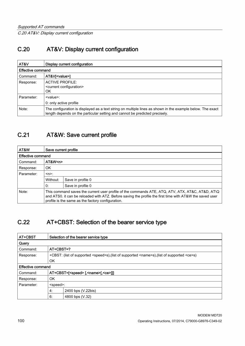
Supported AT commands C.20 AT&V: Display current configuration
MODEM MD720 100 Operating Instructions, 07/2014, C79000-G8976-C349-02
C.20 AT&V: Display current configuration AT&V Display current configuration Effective command Command: AT&V[<value>] Response: ACTIVE PROFILE:
<current configuration> OK
Parameter: <value>: 0: only active profile
Note: The configuration is displayed as a text string on multiple lines as shown in the example below. The exact length depends on the particular setting and cannot be predicted precisely.
C.21 AT&W: Save current profile AT&W Save current profile Effective command Command: AT&W<n> Response: OK Parameter: <n>:
Without: Save in profile 0 0: Save in profile 0
Note: This command saves the current user profile of the commands ATE, ATQ, ATV, ATX, AT&C, AT&D, AT\Q and ATS0. it can be reloaded with ATZ. Before saving the profile the first time with AT&W the saved user profile is the same as the factory configuration.
C.22 AT+CBST: Selection of the bearer service type AT+CBST Selection of the bearer service type Query Command: AT+CBST=? Response: +CBST: (list of supported <speed>s),(list of supported <name>s),(list of supported <ce>s)
OK Effective command Command: AT+CBST=[<speed> [,<name>[,<ce>]]] Response: OK Parameter: <speed>:
4: 2400 bps (V.22bis) 6: 4800 bps (V.32)

Supported AT commands C.23 AT+CCLK: Clock
MODEM MD720 Operating Instructions, 07/2014, C79000-G8976-C349-02 101
AT+CBST Selection of the bearer service type 7: 9600 bps (V.32) 68: 2400 bps (V.110 or X.31 flag stuffing) 70: 4800 bps (V.110 or X.31 flag stuffing) 71: 9600 bps (V.110 or X.31 flag stuffing) <name>: 0: Data connection asynchronous (UDI or 3.1 kHz modem) 1: Not supported <ce>: 0: Transparent 1: non-transparent
Note: The effective command selects the bearer service <name> the transmission speed <speed>, and the connection element <ce> for outgoing connections.
C.23 AT+CCLK: Clock AT+CCLK Clock Test Command: +CCLK=? Response: OK Query Command: +CCLK=? Response: +CCLK: <time> Effective command Command: AT+CCLK=<time> Response: OK
+CME ERROR: <err> Parameter: <time>:
string variable; the format is "yy/MM/dd,hh:mm:ss±tz", where yy: Year MM: Month dd: Day hh: Hours mm: Minutes ss: seconds zz: Time zone, the difference between the local time and GMT, given in 15 minute divisions; the
range of values is between -47 and +48. Example: 6. May, 1994, 22:10:00 GMT+2 hours corresponds to "94/05/06,22:10:00+08"
Note: -

Supported AT commands C.24 AT+CGDCONT: Specify the PDP context
MODEM MD720 102 Operating Instructions, 07/2014, C79000-G8976-C349-02
C.24 AT+CGDCONT: Specify the PDP context AT+CGDCONT Specify the PDP context Test Command: AT+CGDCONT=? Response: +CGDCONT: (Range of supported <cid>s), <PDP_type>, (List of supported <d_comp>s), (List of
supported <h_comp>s) Query: Command: AT+CGDCONT? Response: If +CGDCONT is set:
+CGDCONT: <cid>, <PDP_type>, <APN>,<PDP_addr>, <d_comp>, <h_comp> If +CGDCONT is not set: OK
Effective command: Command: +CGDCONT=<cid> ,<PDP_type> ,<APN> ,<PDP_addr> ,<d_comp> ,<h_comp> Response: OK Parameter: <cid>: (Local) context identification parameter
<PDP_type>: Packet Data Protocol type A string variable that specifies the type of packet data protocol. Only IP (Internet Protocol - IETF STD 5) is supported. <APN>: Access point name Access Point Name - A string variable with a logical name that is used to specify the GGSN for IP networks outside the GPRS. <PDP_address>: A string parameter that specifies the MT in the address space for the PDP. As only IP is currently supported, this will be an IP address. If the value is zero ("0.0.0.0" or 0), the value can be supplied device during startup. Otherwise, if there is an error a dynamic address will be requested. The request continues to return the zero string even if an address has been assigned during the PDP startup. It is possible that the assigned address can be read using the +CGPADDR command. <d_comp>: A numeric parameter that controls PDP data compression. 0: Off (default and only value supported: no PDP data compression) <h_comp>: A numeric parameter that controls PDP header compression. 0: Off (default and only value supported: no PDP data compression)
Note: The effective command specifies the PDP context parameter values for a PDP context identified by the (local) context identification parameter <cid>. The number of PDP contexts that can be in a defined status at the same time is specified by the range returned in response to the Test command. The special form of the +CGDCONT= <cid> command results in values not being defined for the context number <cid>.

Supported AT commands C.25 AT+CGSN: Query IMEI
MODEM MD720 Operating Instructions, 07/2014, C79000-G8976-C349-02 103
C.25 AT+CGSN: Query IMEI AT+CGSN Query IMEI Test Command: AT+CGSN=? Response: OK Query: Command: AT+CGSN Response: <sn> (identification text for determining of the individual device)
O Parameter: - Note: -
C.26 AT+CIMI. Query the IMSI AT+CIMI Request IMSI Test Command: AT+CIMI=? Response: OK Query: Command: AT+CIMI Response: <IMSI> (International Mobile Subscriber Identity)
OK Parameter: - Note: -
C.27 AT+CMGD: Delete an SMS message AT+CMGD Delete an SMS Test Command: AT+CMGD=? Response: OK or +CMS ERROR: <err> Effective command Command: +CMGD=<index> Response: OK or +CMS ERROR: <err> Parameter: <index>:
1 – n: Storage location on the SIM card; n depends on the storage capacity of the SIM card. <err>: Error code
Note: -

Supported AT commands C.28 AT+CMGF: Select SMS message format
MODEM MD720 104 Operating Instructions, 07/2014, C79000-G8976-C349-02
C.28 AT+CMGF: Select SMS message format AT+CMGF Select SMS message format Test Command: AT+CMGF=? Response: +CMGF: (list of supported <mode>s)
OK Query Command: AT+CMGF? Response: +CMGF: <mode>
OK Effective command Command: AT+CMGF=[<mode>] Response: OK Parameter: <mode>:
0: PDU mode 1: Text mode
Note: -
C.29 AT+CMGL: List SMS messages in preferred storage AT+ CMGL List SMS messages in preferred storage Test Command: AT+CMGL=? Response: +CMGL: (list of supported variables <stat>)
OK Effective command Command: AT+CMGL[=<stat>]

Supported AT commands C.29 AT+CMGL: List SMS messages in preferred storage
MODEM MD720 Operating Instructions, 07/2014, C79000-G8976-C349-02 105
AT+ CMGL List SMS messages in preferred storage Response: In text mode (+CMGF=1) and with a successfully executed command and SMS-SUBMITs and/or with
SMS-DELIVERs: If <stat> = "REC READ" or "REC UNREAD" +CMGL: <index>,<stat>,<oa/da>,<scts>,<length> <CR><LF><data><CR><LF> [+CMGL: <index>,<stat>,<oa/da>,<scts>,<length><CR><LF><data> <CR><LF>[...]] If <stat> = "STO UNSENT" or "STO SENT" +CMGL: <index>,<stat>,<oa/da>,<length> <CR><LF><data><CR><LF> [+CMGL: <index>,<stat>,<oa/da>,<length><CR><LF><data> <CR><LF>[...]] Misc. +CMS ERROR: <err> In PDU mode (+CMGF=0) and with successfully executed command: [+CMGL: <index>,<stat>,[<alpha>],<length><CR><LF><pdu> [<CR><LF>+CMGL:<index>,<stat>,[<alpha>],<length><CR><LF><pdu> [...]]] OK
Parameter: <index>: Integer variable; value from the available storage space area <stat>: Integer variable; specifies the status of the messages in storage based on defined values: 0: "REC UNREAD" Message received, unread (e.g. new message) 1: "REC READ" Message received, read 2: "STO UNSENT" Message stored, unsent (only with SMS) 3: "STO SENT" Message stored, sent (only with SMS) 4: "ALL" All messages (only with +CMGL command) <oa/da>: GSM 03.40: TP-Originating-Address / TP-Destination-Address; Address value field as string variable <scts>: GSM 03.40: TP-Service-Centre-Time-Stamp as string variable <length>: Integer variable indicating the length in characters of the message text (message body) in variable <data> <data>: GSM 03.40: Message text (TP-User-Data) in text mode responses
Note: The effective command returns the status <stat> of the preferred SMS storage <mem1>.

Supported AT commands C.30 AT+CMGR: Read SMS message
MODEM MD720 106 Operating Instructions, 07/2014, C79000-G8976-C349-02
C.30 AT+CMGR: Read SMS message AT+CMGR Read SMS message Test Command: AT+CMGR=? Response: OK Effective command Command: AT+CMGR=<index> Response: In text mode (+CMGF=1)
If command is successful and "SMS-DELIVER": +CMGR: <stat>,<oa>,<scts>,<length> <CR><LF><data><CR><LF> If command is successful and "SMS-SUBMIT": +CMGR: <stat>,<da>,<length> <CR><LF><data><CR><LF> Misc. +CMS ERROR: <err> In PDU mode (+CMGF=0) and successfully executed command: +CMGR: <stat>,[<alpha>],<length><CR><LF><pdu> OK
Parameter: Refer to +CMGL Note: Effective command returns message from storage <index> from preferred message storage <mem1>.
Status of the message and entire message content <pdu> is output. If the status of the message is 'received unread', the status changes to 'received read' and the message content is no longer output.
C.31 AT+CMGS: Send SMS message AT+CMGS Sending messages by SMS Test Command: AT+CMGS=? Response: OK Effective command Command: In text mode (+CMGF=1):
+CMGS=<da>,<toda><CR> > Enter text<ctrl-Z/ESC> In PDU mode (+CMGF=0): AT+CMGS=<length><CR> SMS-Text <ctrl+Z/ESC>
Response: In text mode (+CMGF=1) after sending successfully: +CMGS: 0 If sending fails: +CMS ERROR: <err>

Supported AT commands C.32 AT+CMGW: Store SMS message
MODEM MD720 Operating Instructions, 07/2014, C79000-G8976-C349-02 107
AT+CMGS Sending messages by SMS In PDU mode (+CMGF=0) after sending successfully: +CMGS: <mr>[,<ackpdu>] OK
Parameter: <da>: Enter phone number (with quotes " ") <toda>: 145: Enter phone number incl. country code, e.g. +49xxxxx for Germany 129: Enter phone number without country code <mr>: Reference number of the SMS (TP Message Reference) as integer variable; consecutive number. <ackpdu> Optional return value (network-dependent); integer variable RP-User-Data - Element of the RP-ACK PDU; the format is the same as for the <pdu> (SMS content) only without the SMSC address field. <length> Integer variable that specifies the length of the text body <data> (or <cdata> in characters in text mode (+CMGF=1). In PDU mode (+CMGF=0), specifies the length of the actual TP data unit in bytes (the RP layer SMSC address octets are not counted)
Note: • The device sends 4 characters <CR><LF><greater than><space> (IRA 13, 10, 62, 32) after command is completed with <CR>. After that the PDU data can be transferred from the connected the device.
• The DCD signal is active while PDU data is being transferred. • the local echo is controlled with ATE. • In PDU mode, the SMS text is entered in a line in hexadecimal format. The device converts this
coding into PDU octets. • When the length octet of the SMSC address (transferred in the PDU) equals zero, the SMSC
address defined with the +CSCA command is used. • The key combination <Ctrl+Z> (IRA 26) is used to identify the end of the SMS text (in the PDU
format). • Sending can be canceled with <ESC> (IRA 27).
C.32 AT+CMGW: Store SMS message AT+CMGW Store SMS message Effective command Command: In text mode (+CMGF=1):
AT+CMGW=<oa>/<da>[, [<tooa>/<toda>][, <stat>]]<CR> Text can be entered. <CTRL-Z>/<ESC> In PDU mode (+CMGF=0): AT+CMGW=<length>[, <stat>]<CR> PDU can be entered. <CTRL-Z>/<ESC>

Supported AT commands C.33 AT+CNMI: Display new SMS message
MODEM MD720 108 Operating Instructions, 07/2014, C79000-G8976-C349-02
AT+CMGW Store SMS message Response: In text mode (+CMGF=1):
+CMGW: <index1> OK If the action fails: ERROR +CMS ERROR: <err> In PDU mode (+CMGF=0) after sending successfully: +CMGW: <index1> OK
Parameter: <oa/da>: TP-Originating-Address / TP-Destination-Address; Address value field as string variable <tooa> Type of originating address (string variable) For the default, see <toda>. <toda>: Type of destination address (string variable) 145: Enter phone number incl. country code, e.g. +49xxxxx for Germany 129: Enter phone number without country code <stat>: Integer variable Specifies the status of the messages in storage based on defined values: 2: "STO UNSENT" Message stored, unsent (only with SMS) 3: "STO SENT" Message stored, sent (only with SMS) <length> Integer variable Specifies the length of the text body <data> (or <cdata> in characters in text mode (+CMGF=1). In PDU mode (+CMGF=0), specifies the length of the actual TP data unit in bytes (the RP layer SMSC address bytes are not counted in the length).
Note: The command saves an SMS message entered by the local application in memory. After saving, the memory location <index> is output. The status of the message is set to "stored unsent" as default.
C.33 AT+CNMI: Display new SMS message AT+CNMI Display new SMS message Test Command: AT+CNMI=? Response: +CNMI: (list of supported <mode>s), (list of supported <mt>s), (list of supported <bm>s), (list of
supported <ds>s), (list of supported <bfr>s) 2. Query Command: AT+CNMI? Response: +CNMI: <mode>,<mt>,<bm>,<ds>,<bfr>,OK

Supported AT commands C.34 AT+CNUM: Subscriber phone number
MODEM MD720 Operating Instructions, 07/2014, C79000-G8976-C349-02 109
AT+CNMI Display new SMS message Effective command Command: AT+CNMI=[<mode>][,<mt>][,<bm>][,<ds>][,<bfr>] Response: OK Parameter: <mode>:
0: Spontaneous notifications are stored temporarily on the device. If the buffer for spontaneous notifications is full, the notifications can be stored elsewhere or the oldest notifications are discarded and replaced by the new notifications.
1: Notifications are discarded and new spontaneous notifications about newly received SMS messages are rejected if the connection between the device and the connected application is already busy, for example when there is an established data connection. Otherwise the notifications are forwarded directly to the connected application.
2: Spontaneous notifications are buffered on the device if the connection between the device and the connected application is busy, for example when there is an established data connection. and flush them to the connected application after reservation. Otherwise the notifications are forwarded directly to the connected application.
3: Not supported <mt>: 0: No SMS-DELIVER notifications are forwarded to the connected application. 1: If SMS-DELIVER notifications are stored on the device, the spontaneous notification +CMTI:
<mem>,<index> forwards information about the storage location to the connected application. <bm>: 0: No CBM notifications are forwarded to the connected application. <ds>: 0: No SMS STATUS REPORTs are forwarded to the connected application <bfr>: 0: The stored notifications are sent.
Note: -
C.34 AT+CNUM: Subscriber phone number AT+CNUM Subscriber phone number Test Command: AT+CNUM=? Response: OK Effective command Command: AT+CNUM Response: +CNUM: [<alpha1>],<number1>,<type1>[,<speed>,<service>[,<itc>]]
[<CR><LF>+CNUM: [<alpha2>],<number2>,<type2>[,<speed>,<service> [,<itc>]] [...]] OK
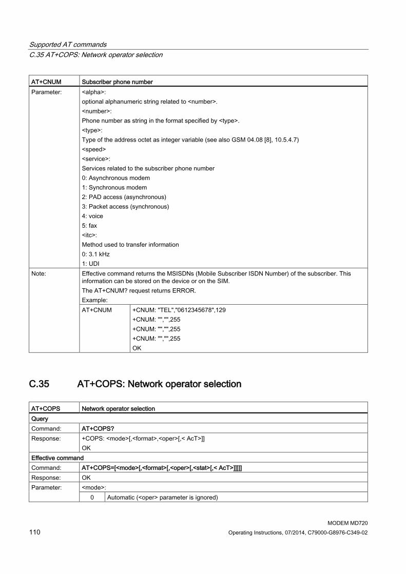
Supported AT commands C.35 AT+COPS: Network operator selection
MODEM MD720 110 Operating Instructions, 07/2014, C79000-G8976-C349-02
AT+CNUM Subscriber phone number Parameter: <alpha>:
optional alphanumeric string related to <number>. <number>: Phone number as string in the format specified by <type>. <type>: Type of the address octet as integer variable (see also GSM 04.08 [8], 10.5.4.7) <speed> <service>: Services related to the subscriber phone number 0: Asynchronous modem 1: Synchronous modem 2: PAD access (asynchronous) 3: Packet access (synchronous) 4: voice 5: fax <itc>: Method used to transfer information 0: 3.1 kHz 1: UDI
Note: Effective command returns the MSISDNs (Mobile Subscriber ISDN Number) of the subscriber. This information can be stored on the device or on the SIM. The AT+CNUM? request returns ERROR. Example: AT+CNUM +CNUM: "TEL","0612345678",129
+CNUM: "","",255 +CNUM: "","",255 +CNUM: "","",255 OK
C.35 AT+COPS: Network operator selection AT+COPS Network operator selection Query Command: AT+COPS? Response: +COPS: <mode>[,<format>,<oper>[,< AcT>]]
OK Effective command Command: AT+COPS=[<mode>[,<format>[,<oper>[,<stat>[,< AcT>]]]]] Response: OK Parameter: <mode>:
0 Automatic (<oper> parameter is ignored)

Supported AT commands C.36 AT+CPAS: Activity status
MODEM MD720 Operating Instructions, 07/2014, C79000-G8976-C349-02 111
AT+COPS Network operator selection 1 Manual (<oper> parameter must be set. Setting of <AcT> is optional.) 2 Not used 3 Setting of the read format; used with <format>. 4 Manual/automatic (<oper> parameter must be set).
If manual selection fails, automatic selection is used (<mode>=0). <format>: Indicates whether the read format is alphanumeric or numeric. See "<oper>" parameter.
0 Long format alphanumeric 1 Short format alphanumeric 2 Numeric
<oper> String in the "<format>" format that identifies the network operator. <stat>: Status of the network operator
0 Unknown 1 Available 2 Currently used 3 Forbidden
<AcT>: Selected access technology
0 GSM 1 GSM Compact 2 UTRAN
Note: The AT+COPS? read command the current settings for the network operator selection. With the write command, the criteria for selecting the network operator can be specified with the dial-in.
C.36 AT+CPAS: Activity status AT+CPAS Activity status Test Command: AT+CPAS=? Response: +CPAS: (list of supported <pas>s)
OK Query: Command: AT+CPAS Response: +CPAS: <pas>
OK Parameter: <pas>:
0: ready Entry of commands possible
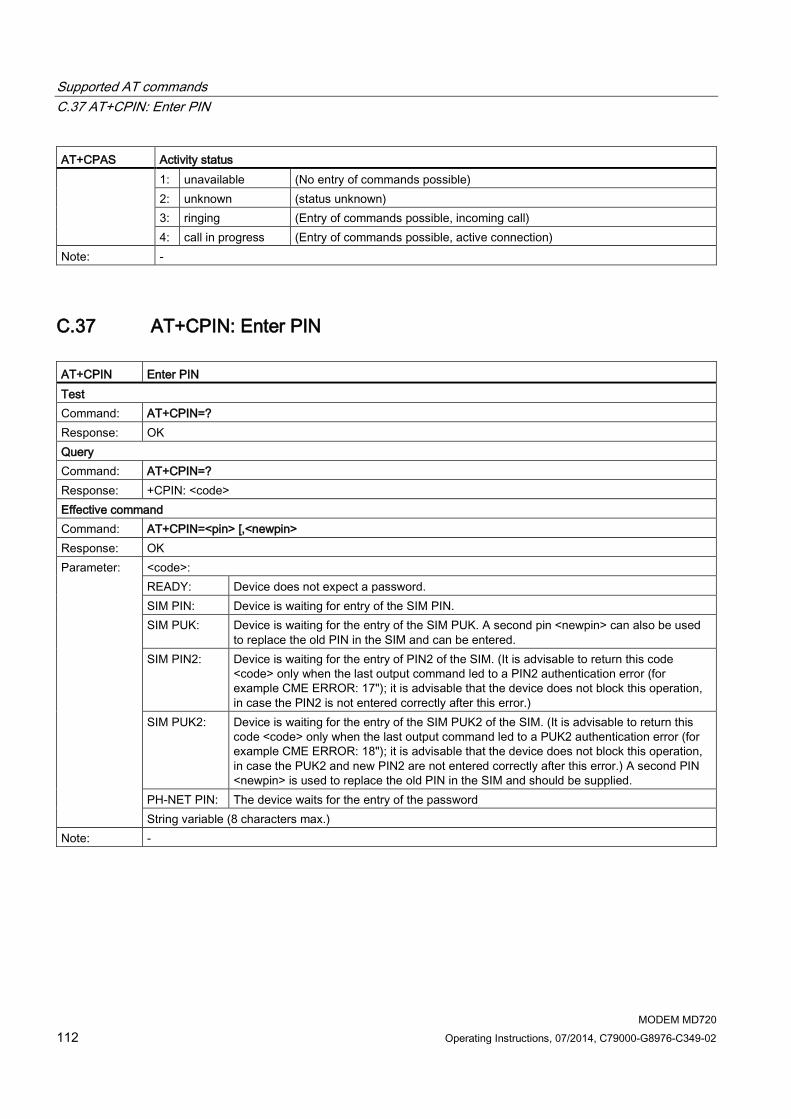
Supported AT commands C.37 AT+CPIN: Enter PIN
MODEM MD720 112 Operating Instructions, 07/2014, C79000-G8976-C349-02
AT+CPAS Activity status 1: unavailable (No entry of commands possible) 2: unknown (status unknown) 3: ringing (Entry of commands possible, incoming call) 4: call in progress (Entry of commands possible, active connection)
Note: -
C.37 AT+CPIN: Enter PIN AT+CPIN Enter PIN Test Command: AT+CPIN=? Response: OK Query Command: AT+CPIN=? Response: +CPIN: <code> Effective command Command: AT+CPIN=<pin> [,<newpin> Response: OK Parameter: <code>:
READY: Device does not expect a password. SIM PIN: Device is waiting for entry of the SIM PIN. SIM PUK: Device is waiting for the entry of the SIM PUK. A second pin <newpin> can also be used
to replace the old PIN in the SIM and can be entered. SIM PIN2: Device is waiting for the entry of PIN2 of the SIM. (It is advisable to return this code
<code> only when the last output command led to a PIN2 authentication error (for example CME ERROR: 17"); it is advisable that the device does not block this operation, in case the PIN2 is not entered correctly after this error.)
SIM PUK2: Device is waiting for the entry of the SIM PUK2 of the SIM. (It is advisable to return this code <code> only when the last output command led to a PUK2 authentication error (for example CME ERROR: 18"); it is advisable that the device does not block this operation, in case the PUK2 and new PIN2 are not entered correctly after this error.) A second PIN <newpin> is used to replace the old PIN in the SIM and should be supplied.
PH-NET PIN: The device waits for the entry of the password String variable (8 characters max.)
Note: -

Supported AT commands C.38 AT+CPMS: Preferred SMS storage
MODEM MD720 Operating Instructions, 07/2014, C79000-G8976-C349-02 113
C.38 AT+CPMS: Preferred SMS storage AT+CGATT Attach to / detach from GPRS Test Command: AT+CPMS=? Response: +CPMS: (list of supported <mem1>s),(list of supported <mem2>s),(list of supported <mem1>s),
OK Query: Command: AT+CPMS? Response: +CPMS: <mem1>,<used1>,<total1>,<mem2>,<used2>,<total2>,<mem3>, <used3>,<total3>
OK Effective command: Command: AT+CPMS= <mem1>,<mem2>,<mem3> Response: +CPMS: <used1>,<total1>,<used2>,<total2>,<used3>,<total3>
OK Parameter: The effective command selects the SMS storage <mem<x>>, used to read, write, etc.
<mem1> Memory area used for listing, reading and deleting messages: "SM" Message storage on the SIM card "ME" message storage on device "MT" Total message storage on SIM card and device <mem2> Memory area used for writing and sending messages: "SM" Message storage on the SIM card "ME" message storage on device "MT" Total message storage on SIM card and device <mem3> Memory area used for temporary storage of received messages, if forwarding to the connected application is not possible. Refer to AT command AT+CNMI with parameter <mt>=2 "SM" Message storage on the SIM card "MT" Total message storage on SIM card and device <usedx> Number of messages currently stored in <memx>. <totalx> Number of messages that can be stored in<memx>.
Note: Example: AT+CPMS=? +CPMS: ("ME","SM","MT")
OK AT+CPMS? +CPMS: "ME",0,100, "SM",0,10, "MT",0,110
OK AT+CPMS="ME" +CPMS: 0,100,0,10,0,110
OK Up to an including firmware version 1.6, only the message storage "MT" was supported for <mem3>.

Supported AT commands C.39 AT+CPOL: List of preferred network operators
MODEM MD720 114 Operating Instructions, 07/2014, C79000-G8976-C349-02
C.39 AT+CPOL: List of preferred network operators AT+CPOL List of preferred network operators Query Command: AT+CPOL? Response: +CPOL: <index>, <format>, <operator>
+CPOL: ... OK
Effective command Command: AT+CPOL: <index>, <format>, <operator> Response: OK Parameter: <index>:
(Consecutive) number of the network operator in the list <format>: Format of the output (always 2 = numeric) <operator> Numeric identifier of the network operator (MCC/MNC)
Note: As a query, AT+CPOL returns the list of GSM network operators into whose networks the MD720 can dial in. As effective command, AT+CPOL edits the GSM network operator into whose network the MD720 dials in.
C.40 AT+CRC: Set cellular result codes for incoming calls AT+CRC Set cellular result codes for incoming calls Test Command: AT+CRC=? Response: +CRC: (list of <mode>) Query Command: AT+CRC? Response: +CRC:<mode> Effective command Command: AT+CRC=[<mode>] Response: OK Parameter: <mode>:
0: Expanded output disabled 1: Expanded output enabled
Note: When extended output is enabled, the output is in the format: +CRING: <type> with <type> : FAX, DATA or VOICE

Supported AT commands C.41 AT+CREG: Network registration
MODEM MD720 Operating Instructions, 07/2014, C79000-G8976-C349-02 115
C.41 AT+CREG: Network registration AT+CREG Network registration Test Command: AT+CREG=? Response: +CREG: (list of supported <n>s)
OK Query Command: AT+CREG? Response: +CREG: <n>,<stat>[,<lac>,<ci>]
OK Effective command Command: AT+CREG=<n>,<stat> Response: OK Parameter: <n>:
0: No output of spontaneous messages for network registration 1: Output of spontaneous messages for network registration +CREG: <stat> 2: Output of spontaneous messages for network registration with location information +CREG:
<stat>[,<lac>,<ci>] <stat>: 0: Not registered. The device is not currently searching for a new network to register with. 1: Registered, home network 2: Not registered. The device is currently searching for a new network to register with. 3: Attachment denied 4: Status unknown 5: Attached, roaming <lac>: String variable; two byte "location area code" in hexadecimal format (e.g. "00C3" equals 195 in decimal). <ci>: String variable; two byte "cell ID" in hexadecimal format.
Note: Effective command controls the presentation of an spontaneous messages: +CREG: <stat> when <n>=1 and there is a change in the device network registration status, or +CREG: <stat>[,<lac>,<ci>] when <n>=2 and there is a change of the network cell
C.42 AT+CRLP: Radio link protocol AT+CRLP Radio link protocol Test Command: +CRLP=?

Supported AT commands C.43 AT+CSCA: SMSC address
MODEM MD720 116 Operating Instructions, 07/2014, C79000-G8976-C349-02
AT+CRLP Radio link protocol Response: +CRLP:
(list of supported <iws>s), (list of supported <mws>s), (list of supported <T1>s), (list of supported <N2>s),<ver1>, (list of supported <T4>s)
Query Command: +CRLP? Response: +CRLP: <iws>,<mws>,<T1>,<N2>,<ver1>,<T4> Effective command Command: AT+CRLP=<iws>[,<mws>[,<T1>[,<N2>[,<ver>[,<T4>]]]]] Response: OK Parameter: <ver>: RLP version number as integer variable; version display 0 means "RLP version display not
available" <iws>: Window size IWF to MS <mws>: Window size MS to IWF <T1>: Confirmation timer T1 <N2>: Retransmission attempts N2 <T4>: Re-sequencing period T4 as integer variable
Note: Basic settings and value ranges depend on the RLP Version; see GSM 04.22 [18]. T1 and T4 are specified in units of 10 ms.
C.43 AT+CSCA: SMSC address AT+CSCA Short Message Service Center address Test Command: AT+CSCA=? Response: OK Query Command: AT+CSCA=? Response: +CSCA: <sca>,<tosca> Effective command Command: AT+CSCA=<sca>[,<tosca>] Response: OK Parameter: <sca>:
Telephone number of the SMSC entered with quotes " " <tosca>: 145: Enter phone number incl. country code, e.g. +49xxxxx for Germany 129: Enter phone number without country code
Note: The effective command updates the SMSC via which SMS messages from the device are sent. In PDU mode, the SMSC entered here is also used if the length for the SMSC address entered in the PDU is zero.
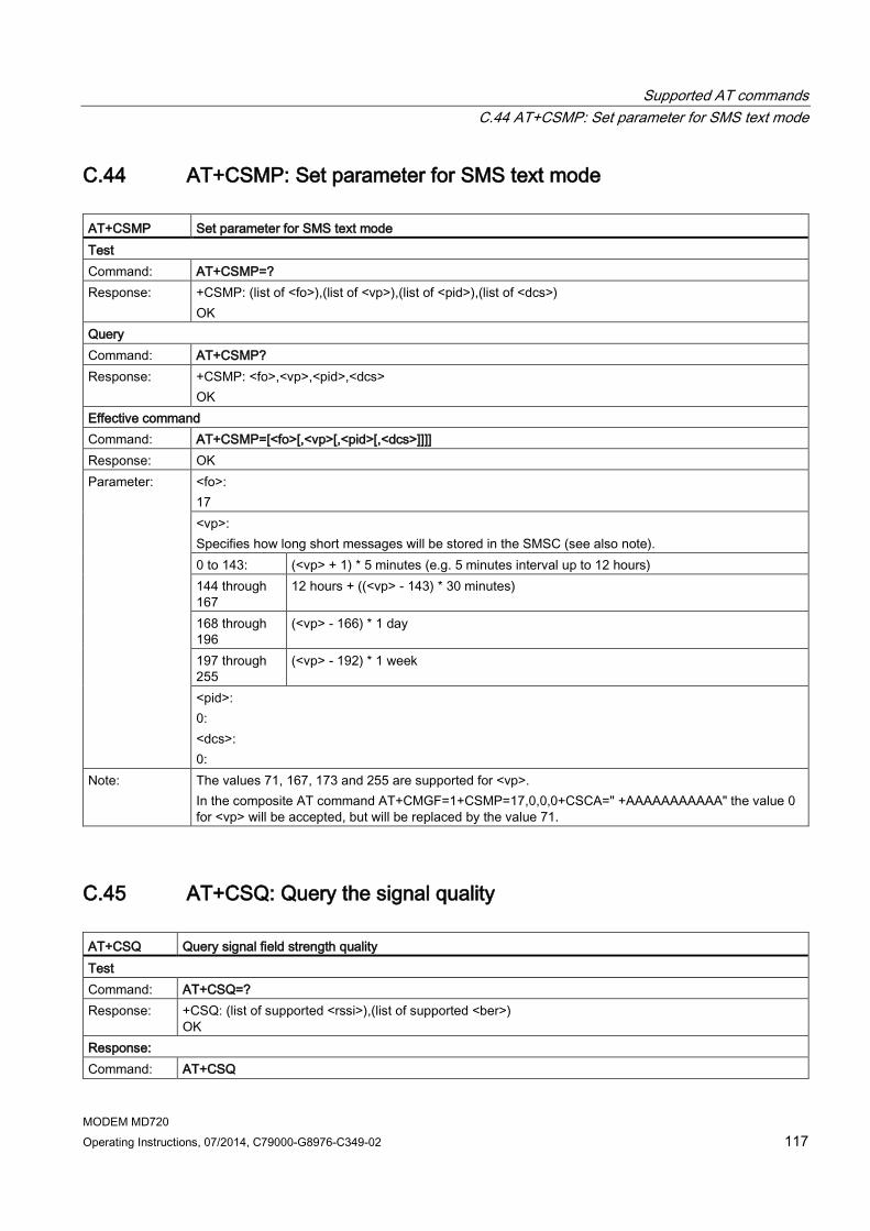
Supported AT commands C.44 AT+CSMP: Set parameter for SMS text mode
MODEM MD720 Operating Instructions, 07/2014, C79000-G8976-C349-02 117
C.44 AT+CSMP: Set parameter for SMS text mode AT+CSMP Set parameter for SMS text mode Test Command: AT+CSMP=? Response: +CSMP: (list of <fo>),(list of <vp>),(list of <pid>),(list of <dcs>)
OK Query Command: AT+CSMP? Response: +CSMP: <fo>,<vp>,<pid>,<dcs>
OK Effective command Command: AT+CSMP=[<fo>[,<vp>[,<pid>[,<dcs>]]]] Response: OK Parameter: <fo>:
17 <vp>: Specifies how long short messages will be stored in the SMSC (see also note). 0 to 143: (<vp> + 1) * 5 minutes (e.g. 5 minutes interval up to 12 hours) 144 through 167
12 hours + ((<vp> - 143) * 30 minutes)
168 through 196
(<vp> - 166) * 1 day
197 through 255
(<vp> - 192) * 1 week
<pid>: 0: <dcs>: 0:
Note: The values 71, 167, 173 and 255 are supported for <vp>. In the composite AT command AT+CMGF=1+CSMP=17,0,0,0+CSCA=" +AAAAAAAAAAA" the value 0 for <vp> will be accepted, but will be replaced by the value 71.
C.45 AT+CSQ: Query the signal quality AT+CSQ Query signal field strength quality Test Command: AT+CSQ=? Response: +CSQ: (list of supported <rssi>),(list of supported <ber>)
OK Response: Command: AT+CSQ

Supported AT commands C.46 AT+IPR: Set the transmission speed of the X1 interface
MODEM MD720 118 Operating Instructions, 07/2014, C79000-G8976-C349-02
AT+CSQ Query signal field strength quality Response: +CSQ: <rssi>,<ber>
OK Parameter: <rssi>:
0: 113 dBm or less 1: 111 dBm 2...30: 109 ... 53 dBm 31: 51 dBm or more 99: Unknown or not measurable <ber>: 0...7: According to RxQual values in the table in GSM 05.08 [20], 8.2.4 99: Unknown or not measurable
Note: The read command AT+CSQ? results in "ERROR".
C.46 AT+IPR: Set the transmission speed of the X1 interface AT+IPR Set the transmission speed of the X1 interface Test Command: AT+IPR=? Response: + IPR (list of the supported fixed transmission speeds) Query Command: AT+IPR? Response: +IPR: <rate> OK Effective command Command: AT+IPR=<rate> Response: OK Parameter: <rate> (bps)
1200 2400 4800 9600 19200 38400 57600

MODEM MD720 Operating Instructions, 07/2014, C79000-G8976-C349-02 119
Documentation references D
Where to find Siemens documentation ● You will find the order numbers for the Siemens products of relevance here in the
following catalogs:
– SIMATIC NET Industrial Communication / Industrial Identification, catalog IK PI
– SIMATIC Products for Totally Integrated Automation and Micro Automation, catalog ST 70
You can request the catalogs and additional information from your Siemens representative.
● You will find SIMATIC NET manuals on the Internet pages of Siemens Automation Customer Support: (http://support.automation.siemens.com/WW/view/en)
Enter the entry ID of the relevant manual as the search item. The ID is listed below some of the reference entries in brackets.
As an alternative, you will find the SIMATIC NET documentation on the pages of Product Support:
10805878 (http://support.automation.siemens.com/WW/view/en/10805878)
Go to the required product group and make the following settings:
"Entry list" tab, Entry type "Manuals / Operating Instructions"
You will find the documentation for the SIMATIC NET products relevant here on the data medium that ships with some products:
– Product CD / product DVD or
– SIMATIC NET Manual Collection
D.1 /1/ SIMATIC NET SINAUT MICRO SC system manual Siemens AG Entry ID: 23119827 (http://support.automation.siemens.com/WW/view/en/23119827)
D.2 /2/ SIMATIC NET TELECONTROL SERVER BASIC

Documentation references D.3 /3/
MODEM MD720 120 Operating Instructions, 07/2014, C79000-G8976-C349-02
Operating Instructions Siemens AG entry ID: 50898745 (http://support.automation.siemens.com/WW/view/en/50898745)
D.3 /3/ ETSI TS 100 916 Digital cellular telecommunications system (Phase 2+) AT Command set for GSM Mobile Equipment (ME) (3GPP TS 07.07 version 7.8.0 Release 1998) (http://www.etsi.org/deliver/etsi_ts/100900_100999/100916/07.08.00_60/ts_100916v070800p.pdf)
See also: ETSI (http://www.etsi.org) ETSI search (http://webapp.etsi.org/workprogram/SimpleSearch/QueryForm.asp)

MODEM MD720 Operating Instructions, 07/2014, C79000-G8976-C349-02 121
Index
A Antennas, 89 Article number, 3
C Compatibility, predecessor module, 3 Connection attempts (MD720), 62 Connection resources, 13
D Device replacement, 29
F Firmware version, 3
G Glossary, 5
H Hardware product version, 3
I Inter-station communication, 13
M MSC protocol
Functions, 60 Setting, 33
MSCsec Support of the protocol, 34
MSCsec protocol Functions, 60 Setting, 33
P Predecessor module, compatibility, 3
R Redial delay, 62
S S7 systems, connectable, 12 Safety notices, 21 Service & Support, 6 Service call number, 74 SIM card without PIN, 25 SIMATIC NET glossary, 5 Startimg up the MD720, 29 Starting the MD720, 29
T Terminal program, 65 Training, 6

Index
MODEM MD720 122 Operating Instructions, 07/2014, C79000-G8976-C349-02