teleoperation of a surgical robot using force...
TRANSCRIPT

Teleoperation of a surgical robot using forcefeedback
Daniel Bolgar, Simon Krogh, Filip Maric, Nicolas SilvaniAalborg University
Department of Electronic Systems{dbolga16, skrogh13, fmaric16, nsilva16}@student.aau.dk
Abstract—Haptic feedback is a way of transferring information tothe user via the sense of touch, usually through the same inputdevice the user gives commands with. This makes it ideal forteleoperating tasks requiring precision in applied force, roboticminimally invasive surgery (MIS) being a prime example. Cur-rently, haptic feedback in teleoperation is subject to numerousconstraints on time delay and accuracy. Nonetheless, resultsshow that implementing this type of feedback in teleoperatedrobotic surgery results in a higher successes rate compared tothe traditional robotic MIS. In this paper, we focus on improvingthe haptic feedback on the da Vinci robot at Aalborg Universityusing the existing hardware. The method involves using a state-of-the-art haptic device to control a surgical tool serving as therobot’s end-effector. Since the dynamics of the surgical tool arestrongly nonlinear, estimation techniques are used to calculatereaction forces on the device. Changes are made to the existingcommunication protocols in order to reduce time delay.
I. INTRODUCTION
Interest in robotic surgery has increased over the last coupleof years. Increased precision provided by surgical robots intro-duces a decrease in tissue damage, thus reducing the recoverytime [1]. Robots used in robotic surgeries have an attachedend-effector that is used as a surgical tool. One such tool isthe EndoWrist. The main advantage of the EndoWrist lies inits construction, as it is made to be manipulated in a similarmanner to the operators wrist. During surgery the operatorreceives 3D video feedback from the control loop.
The problem with the operator having exclusively visualfeedback lies in the fact that the surgeon has to estimatethe force applied by observing the color changes of the skinand organs for each maneuver. This constant effort from theoperator not only increases the operation time but also leads toerrors such as thread breaking during stitching or damagingtissues by applying too much force [2]. It has been shownexperimentally that haptic feedback has a considerably positiveeffect on the reduction of surgical error [3].
The purpose of haptic feedback in Robotic MIS (RMIS) is torestore the sense of touch for the surgeon. To do so, differentapproaches have been studied such as vibrotactile feedback[4] [5], force feedback [6] or both [7]. However, most of thesolution developed introduce new hardware on the robot, suchas sensors or processing units. Some studies on force feedbackwithout additional sensors, have shown promising results [8].
Although force feedback still requires a haptic feedback devicefor the surgeon, the implementation on the robot can be madecompletely by software.
Direct force feedback method involves calculating the feed-back from the resistance affecting the actuators. However, asthe tool is highly nonlinear, the output power is lower than theinput power, due to the tool’s inherent damping. Any forcesrelated to the construction of the robot are not desired in thefeedback as the operator would not feel them when holdinga tool. In order for the operator to feel as if he was directlyholding the tool the control system should be transparent tohim.
The haptic feedback could be done as direct force feedbackcalculated from the resistance affecting the actuators, but asthe tool is highly nonlinear, the transparency of the controllerwould suffer from it. It would be possible to solve this problemby implementing a sensor on the end-effector to measure theforce, but due to the demand for high hygiene, the toolshave to be sterilized at temperatures over a 100◦ C whichcould damage the sensor. Furthermore, each surgical tool hasto be discarded after a few uses [9]. This means that thecost of the tool has to stay as low as possible and thereforemake the idea of implementing an expensive sensor not ideal.Therefore the force feedback has to be estimated through theactuators, which requires a dynamic model of the tool. Fromthis model the forces related to the actuation of the tool can beestimated and the external forces applied at the end-effectorcan be computed. The response time and the frequency ofthe force feedback control loop have to be considered asany of those could break the transparency of the controllerif too high. The frequency of the control loop is directlyrelated to the frequency of the communication between thedifferent components of the system. It is widely discussedwhat the minimum refresh rate of the feedback loop shouldbe but seems to be somewhere between 300 Hz and 1000 Hzdepending of the hardness of the object [10].
In this paper, an attempt is made to implement a force feedbackon a setup emulating the essential parts of the da Vinci Robotwithout implementing new hardware. To do so, a dynamicmodel is derived and a control strategy is proposed. The aimedfrequency for the feedback loop is 550 Hz, to reach thatgoal analysis of the communication protocol is provided. In

section II, we will take an overview of our proposed controlsystem as a whole, briefly presenting each of the componentsand their interaction. Section III will cover the methods usedto create a dynamic model of the EndoWrist and proposedmethods of translating the estimated force to actual forcefed back to the operator. Section IV contains descriptions ofthe modification made in order to improve the refresh rateof the communication between devices. Finally, we presentthe experimental results in Section V and and draw a shortconclusion in Section VI.
II. SYSTEM OVERVIEW
A da Vinci robot with connected EndoWrists has four armswith 6 - 7 actuated Degrees Of Freedom (DOF) each. Eacharm has its own drivers and an embedded system controllingit. The surgeon sends the commands to the embedded systemby controlling the console.
As mentioned in Section I, the EndoWrist is highly nonlinearand constitute most of the challenge in the modelization of onearm of the robot, thus, if the force feedback can effectivelybe applied to the tool, it can be extended to the arm. Aseach arm is independent, the system designed for one armcan be extended to the full arm, the same applies to thetool. The setup used in the present project only controls oneEndoWrist which has four DOF and is further described inSection II-B.To control the EndoWrist, the embedded systemof the robot is used. On a da Vinci robot the surgeon performsthe operation from a console that communicates with the robot.The manipulators for the robot do not implement an interfacefor haptic feedback, thus, a haptic device, a Geomagic Touch(GT), is used in this setup instead of the device used on theofficial console. This device is further described in SectionII-A.As force estimation requires computational power and aninterface is required to exchange information between GT andembedded system, a computer is added to the system andconnected to both devices using Ethernet cables. The entiresetup is represented in Fig. 1
Geomagic Touch Computer
EmbeddedSystemMotor driverEndoWrist
Console
da Vinci robot
Fig. 1: Block diagram representing the system.
A. Geomagic touch
The Geomagic Touch is a haptic feedback device, which hasthe ability to actuate its joints in such a way that the user feelsresistance when moving the pen.
(a) Overview of the GeomagicTouch’s first three joints.
(b) Overview of the GeomagicTouch’s last three joint
Fig. 2: Overview of all the Geomagic Touch’s joints.
On Fig. 2, it can be seen that the Geomagic Touch has sixDOF, where the first three can be actuated, see Fig. 2a. Thismeans that the device has the ability to generate force feedbackwith three translational DOF, in this case corresponding to theEndoWrist’s roll, pitch and yaw movements.
B. EndoWrist
An EndoWrist, see Fig. 3, is a surgical tool for the da Vincirobot which can be manipulated in a similar manner as ahuman wrist. It provides the surgeon the ability to operatewith the robot as the operator would without it. To replicatethe movements of a human wrist, the tool is composed of asystem of cables and pulleys. This construction imitates thehuman tendons however it also introduces nonlinearities inthe tool, and thus, a challenge for controlling or modelingit.
(a) Actuator plates, which canmanipulate the end effector po-sition
(b) End-effector of the En-doWrist
Fig. 3: The EndoWrist and its end-effector
In real operation, each arm has six to seven actuated DOF intotal, however, the EndoWrist itself, when disconnected fromthe robot, only has four DOF. Each DOF is actuated througha plate, see Fig. 3a. The four DOF are roll, pitch, yaw andclamp, see Fig. 3b. The nonlinearities of the tool are analysedwhen building the model in Section III.
III. FORCE ESTIMATION
In order to have a representation of the reaction force on theEndoWrist, estimation is needed. As stated in Section II, theforce cannot be measured on-line using sensors and thus wehave to rely on mathematical models as functions of actuatormeasurements.
A. Mathematical model
The main challenge faced in making a mathematical modellies in the fact that the pulley system of the EndoWrist isnonlinear, and thus its full dynamics cannot be modeled ina straightforward manner. The nonlinearity of the EndoWristdynamics emerges from friction and elasticity of the wirescontrolling the end-effector, which causes multiple pulleys tomove as a result of actuating only one. In other words, tohave an accurate representation of Cartesian force an intricatemodel is required [11].
Another method of approaching this problem lies in creatingmultiple mathematical models pertaining to forces output byactions performed with the EndoWrist. In this manner, thefeedback vector is transformed from Cartesian space to a taskspace in which the chosen actions form a basis. Each elementof the new feedback vector corresponds to an actuated axisof the Geomagic Touch. For the purpose of this system, wechoose to feedback the yaw force generated by the grip actionof the clamp, the force generated by the roll actuator and forceexerted by the clamps pitch movement, as seen in 3.
B. System Identification
Ideally, a mathematical model derived from classical me-chanics would be used to describe the dynamics involved inthe EndoWrist’s movements. However, deriving this modelprecisely enough for grey-box identification has been provendifficult and time consuming due to the nonlinear nature ofthe dynamics.
Models for yaw and pitch forces are derived using black-boxidentification algorithms, which only provide a general modelstructure. A straightforward approach would involve choosinga nonlinear model structure for identification. On the otherhand, stability analysis of nonlinear models is difficult anddue to the nature of the system, only general trends in forceneed to be represented. For this reason it was decided toidentify a linear state-space model which is then used as apart of Hammerstein-Wiener [12] nonlinear model as seen inFig. 4.
InputNonlinearity
LinearBlock
OutputNonlinearity
w(t)u(t) x(t) y(t)
Fig. 4: Block diagram of a Hammerstein-Wiener model.
1) Roll torque: The roll torque, which is determined by theroll actuator and directly rotates the entire tool, making itindependent to the rest of the system. We can model the rolltorque as a state that only depends on input in the state-spacemodel of the system (1).
x(k + 1) =
0 0 00 Apitch 00 0 Ayaw
x(k) +
Broll 0 00 Bpitch 00 0 Byaw
u(k) (1)
y(k + 1) =
Croll 0 00 Cpitch 00 0 Cyaw
x(k) (2)
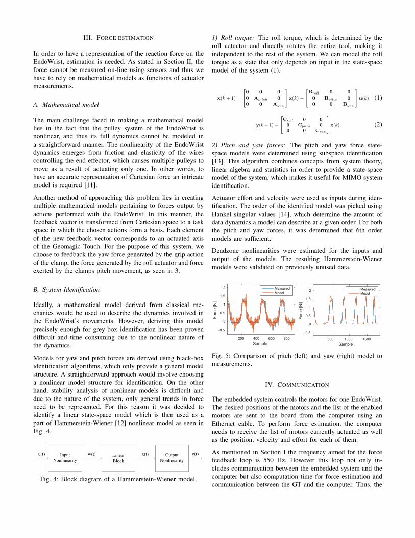
2) Pitch and yaw forces: The pitch and yaw force state-space models were determined using subspace identification[13]. This algorithm combines concepts from system theory,linear algebra and statistics in order to provide a state-spacemodel of the system, which makes it useful for MIMO systemidentification.
Actuator effort and velocity were used as inputs during iden-tification. The order of the identified model was picked usingHankel singular values [14], which determine the amount ofdata dynamics a model can describe at a given order. For boththe pitch and yaw forces, it was determined that 6th ordermodels are sufficient.
Deadzone nonlinearities were estimated for the inputs andoutput of the models. The resulting Hammerstein-Wienermodels were validated on previously unused data.
Sample
200 400 600 800
Forc
e [N
]
-0.5
0
0.5
1
1.5
2 Measured
Model
Sample
500 1000 1500
Fo
rce
[N
]
-0.5
0
0.5
1
1.5
2 Measured
Model
Fig. 5: Comparison of pitch (left) and yaw (right) model tomeasurements.
IV. COMMUNICATION
The embedded system controls the motors for one EndoWrist.The desired positions of the motors and the list of the enabledmotors are sent to the board from the computer using anEthernet cable. To perform force estimation, the computerneeds to receive the list of motors currently actuated as wellas the position, velocity and effort for each of them.
As mentioned in Section I the frequency aimed for the forcefeedback loop is 550 Hz. However this loop not only in-cludes communication between the embedded system and thecomputer but also computation time for force estimation andcommunication between the GT and the computer. Thus, the

communications with the computer must be faster than 550 Hz.The drivers for the GT have a refresh rate of 1000 Hz. Fromexperimentation it was found that the embedded system’s built-in UDP library cannot handle refresh rates higher than 1000Hz. Thus the resulting feedback loop have a refresh rate of500 Hz and not 550 Hz as it was aimed. This study aimsat reaching the maximum frequency of the embedded systemwhich is 1000 Hz.
The original system implements a stream of Javascript ObjectNotation (JSON) [15] files using TCP. However this commu-nication setup can not reach a frequency higher than 100 Hz,which does not match the goal of 1000 Hz. Thus, this sectionfocuses on the modifications applied to the communication inorder to make it reach the requirements.
In order to get a faster communication it was decided to useUDP instead of TCP as it does not retransmit any packets orimplement any features to improve long distance communica-tions. In our system, retransmission of packets would lead toretransmitting obsolete data instead of transmitting new ones.Furthermore, improvements of long distance communicationswould be superfluous since the two devices are directly con-nected.
In addition to the transport protocol, another factor that influ-ence the speed of the communication is the size of the packets.To maximize the number of packets sent, the size of thosepackets must be minimized while keeping the computationtime as low as possible. As stated before, the packets sent tothe computer contain position, velocity, effort and a booleanvalue for each motor. The JSON used in the original systemcreates a human readable file and thus, use one character perdigit in a number. In this setup the numbers can go up to 23characters. The size of the numbers, combined to the additionalcharacters required for the JSON leads to packets of 346 bytesin a worst case scenario, those packets are described in Fig. 6.To reduce the size of those packets, it was decided to interpretthe binary representation as characters instead of the humanreadable format. As the numerical values are stored as floatsfollowing the IEEE 754 standard [16], each of them requirefour bytes. Also, a constant structure was define to remove theneed of control sequences. The new packets are described inFig. 7 and have a constant size of 49 bytes. Thus, the size ofthe packets was reduced by 86%.
To investigate the quality of the communication as a functionof frequency three parameters were measured: the delay be-tween two packets received, the jitter and the error rate. Sincethe computation time on the computer and on the embeddedsystem are very small compared to the frequency of thecommunication, i.e. inferior to 3 µs.
0 {”p4 primary”:{
15 ”positions”: array of 4 positions
125 ,”velocities”: array of 4 velocities
236 ,”efforts”: array of 4 efforts
344 }}
Data
Head
Tail
0 15
0 12 110
0 14 112
0 11 111
0 2
bytesOffset
Fig. 6: Packet using JSON
0 position1 position2 position3 position4
16 velocity1 velocity2 velocity3 velocity4
32 effort1 effort2 effort3 effort448
0 4 8 12 16bytesOffset
XXXX 4 booleans
10
Fig. 7: Packet using the binary representation
V. RESULTS
A. Communication
As shown in TABLE I, when the frequency increases from100 Hz to 500 Hz, so do the jitter and packet loss. Howeverwhen the refresh rate is increased to its maximum valuethe jitter sharply decreases while the packet loss increasessignificantly.
Frequency (Hz) delay (ms) Jitter (µs) Packet loss (%)99 10.1 4.66E-2 0
474 2.1 5.51E-2 0.2638 1.6 1.16E-2 1.2
TABLE I: Measurements of the UDP performances
The goal of 1000 Hz could not be reached when running theentire system. However, as the original communication couldnot exceed the refresh rate of 100Hz a significant improvementis to be noted.
B. Force feedback
As seen in Fig. 8, the yaw force fed back to the user by theGeomagic Touch dynamically corresponds to both the currentincrease and the position error. We have found that applying

0 2 4 6 8 10 12 14−1
−0.5
0
0.5
1
1.5
2
2.5
Time (s)
Am
plitu
deForce feedback response for the clamp
Position ErrorForce feedback [N]Current [A]
Fig. 8: Measurements of the response of the force feedbackfor the clamp
a gain to the feedback provides the user with a better senseof the force exerted by the EndoWrist.
VI. DISCUSSION
When increasing the refresh rate, increasing jitter and packetloss were expected as these parameters are highly correlatedto the network congestion [17]. The drop in jitter whenreaching for higher frequency can be explained by the way thecommunication driver was designed. In order to reach highfrequencies, a trade-off was made by setting a deadline toreceive a packet, if the packet does not meet the deadline, itis discarded. Thus, when the jitter increases, more packets arediscarded, increasing the packet loss. The maximum refreshrate reached does not meet the goal previously set. However,compared to the original system, the refresh rate has beenincreased by more than six folds. Furthermore, the goal of1 kHz was reached when only the communication with theembedded system was enabled, thus it is expected that opti-mizing the program could lead to reaching the goal even withthe entire system running. To further increase the refresh rate,compression of the data was considered and it is believed thatimplementing a fast compression algorithm such as the onedescribed in [18] could reduce the time required to transmit apacket.
By choosing UDP as a transport protocol, every networkreliability feature was removed from the connection whichmatches the demands of our system in term of bandwidth.However, safety needs to be considered for such a system.As such a feature was implemented on both sides of thecommunication in order to detect packet loss and connectiontimeout. The detection of those events allows to stop moving
the end-effector and to notify the operator. In the future,additional steps such as protection against external cyber-attacks and handling of packet losses should be taken in orderto improve the overall safety of the system.
Due to the EndoWrists structure, we have chosen to modelthe dynamics of the tool in a task space consisting of rolltorque and pitch and yaw forces. As we have chosen a data-based approach towards force modeling, all imperfections inthe data acquisition process can affect the result. Roll torqueestimation was simple as the data showed its linear dependenceon the actuator effort.
The yaw (grip) force model has shown an average 77% fitto validation data. While the errors in the model output exist,they usually involve the estimate being slightly lower than theactual force. This is mostly due to the saturation nonlinearityimplemented in the model output, which prevents the linearpart of the model from overshooting the estimate.
Unlike the yaw model, data acquisition for the pitch modelwas more difficult, as the EndoWrists structure the affectedmeasurements. This results in additional nonlinearities in themeasurements, since force wasn’t always applied to an angleperpendicular to the load cell. As a consequence, the modelunderestimates the applied force.
An attempt was made to implement state estimation thecorrect the force estimate. The steady-state Kalman filter wasimplemented, with position error and velocity measurementsused for state estimation. Simulation results have shown thatsuch us system would not improve the systems, as the currentmodels do not capture the dynamics adequatley.
In the future, an improved model could be utilized with stateestimation to provide state feedback control of the outputedforce. The force reference could be directly mapped to theGeomagic Touch movement axes, providing a greater degreeof control to the system.
VII. CONCLUSION
Force feedback has been implemented using the data that canalready be measured on a surgical robot. The refresh rate of thecommunication has been increased by reducing the size of thedata sent and by implementing a new communication protocol.A model that estimates the force has been built. The systemdesigned can be used as a basis for future implementation offorce feedback on a surgical robot.
REFERENCES
[1] P. C. Giulianotti, A. Coratti, M. Angelini, F. Sbrana, S. Cecconi,T. Balestracci, and G. Caravaglios, “Robotics in general surgery: per-sonal experience in a large community hospital,” Archives of surgery,vol. 138, no. 7, pp. 777–784, 2003.
[2] C. Lee, Y. H. Park, C. Yoon, S. Noh, C. Lee, Y. Kim, H. C. Kim, H. H.Kim, and S. Kim, “A grip force model for the da vinci end-effectorto predict a compensation force,” Medical & biological engineering &computing, vol. 53, no. 3, pp. 253–261, 2015.

[3] J. C. Gwilliam, M. Mahvash, B. Vagvolgyi, A. Vacharat, D. D. Yuh,and A. M. Okamura, “Effects of haptic and graphical force feedback onteleoperated palpation,” in Robotics and Automation, 2009. ICRA’09.IEEE International Conference on. IEEE, 2009, pp. 677–682.
[4] M. O. Culjat, C.-H. King, M. L. Franco, C. E. Lewis, J. W. Bisley, E. P.Dutson, and W. S. Grundfest, “A tactile feedback system for roboticsurgery,” in 2008 30th Annual International Conference of the IEEEEngineering in Medicine and Biology Society. IEEE, 2008, pp. 1930–1934.
[5] S. Peddamatham, W. Peine, and H. Z. Tan, “Assessment of vibrotactilefeedback in a needle-insertion task using a surgical robot,” in 2008 Sym-posium on Haptic Interfaces for Virtual Environment and TeleoperatorSystems. IEEE, 2008, pp. 93–99.
[6] T. Ortmaier, B. Deml, B. Kubler, G. Passig, D. Reintsema, andU. Seibold, “Robot assisted force feedback surgery,” in Advances intelerobotics. Springer, 2007, pp. 361–379.
[7] A. R. Peon, C. Pacchierotti, and D. Prattichizzo, “Vibrotactile stimuli foraugmented haptic feedback in robot-assisted surgery,” in World HapticsConference (WHC), 2013. IEEE, 2013, pp. 473–478.
[8] A. M. Okamura, “Haptic feedback in robot-assisted minimally invasivesurgery,” Current opinion in urology, vol. 19, no. 1, p. 102, 2009.
[9] EndoWrist/Single-Site Instrument & Accessory Catalog,http://www.intuitivesurgical.com/products/871145 InstrumentAccessory %20Catalog.pdf, Intuitive Surgery, 2014.
[10] T. R. Coles, D. Meglan, and N. W. John, “The role of haptics in medicaltraining simulators: a survey of the state of the art,” IEEE Transactionson Haptics, vol. 4, no. 1, pp. 51–66, 2011.
[11] C. Y. Kim, M. C. Lee, R. B. Wicker, and S.-M. Yoon, “Dynamic mod-eling of coupled tendon-driven system for surgical robot instrument,”International Journal of Precision Engineering and Manufacturing,vol. 15, no. 10, pp. 2077–2084, 2014.
[12] Y. Zhu, “Estimation of an n–l–n hammerstein–wiener model,” Automat-ica, vol. 38, no. 9, pp. 1607–1614, 2002.
[13] P. Van Overschee and B. De Moor, Subspace identification for linearsystems: Theory—Implementation—Applications. Springer Science &Business Media, 2012.
[14] W. Gawronski and J.-N. Juang, “Model reduction in limited time andfrequency intervals,” International Journal of Systems Science, vol. 21,no. 2, pp. 349–376, 1990.
[15] E. T. Bray, “The javascript object notation (json) data interchangeformat,” RFC 7159, Google, Inc., 2014.
[16] I. S. Committee et al., “754-2008 ieee standard for floating-pointarithmetic,” IEEE Computer Society Std, vol. 2008, 2008.
[17] Cisco. Understanding jitter in packet voice networks (cisco ios plat-forms). http://www.cisco.com/c/en/us/support/docs/voice/voice-quality/18902-jitter-packet-voice.pdf. Document ID: 18902, Accessed: 16-12-2016.
[18] W. N. Ross, “An extremely fast ziv-lempel data compression algorithm,”Proceedings of Data Compression Conference, pp. 362–371, 1991.