telephone entry1) press 99# then press master code, then press (*) (yellow flashes and combo pad is...
TRANSCRIPT

pg 1
TELEPHONE ENTRY
General Information:The AGS Telephone Entry System is a convenient way to control access through a gated entrance with the useof a telephone. This system connects to an existing telephone line in the home. When a visitor presses thebutton on the gate station, all telephones connected on the line will ring and the person may simply pick upany phone to speak with the visitor. If the home owner is already engaged in an outside phone conversation, asound will be heard indicating a call from the gate. The home owner may switch from the outside call to thevisitor and back again. There may be up to two gate stations connected to the system and the home ownermay switch from one station to another, or back to an outside phone conversation. At any time, the gate maybe opened by pressing the ( * ) button on the telephone. There are two types of gate stations for the systemwhich include the TE 001C and the TE 001K. The TE 001C features a combination pad which enables the homeowner or authorized visitor to enter a four digit PIN number to open the gate. This combination pad holds up to120 reprogrammable codes. The TE 001K features a mortise type key switch which allows the gate to beopened with a key. It is possible to re-key or replace the cylinder to match existing keys that are already usedfor the house.
Wiring Requirements:1) Between Gate and House:Run one 18 gauge twisted, shielded pair (two wires) between the Phone Controller in the house and the gatestation at the gate. This 18 gauge wire can be run up to 1,100 feet.
2) Between Gate Operator and Entry Head:Run four 18 gauge wires.
3) Inside House:The TE 001P Phone controller typically will require a twisted pair from the telephone company central office anda twisted pair back out to the phones. In some cases, a central office connection is not necessary. If the phonesystem has two or more lines, any empty line may be used.
Relay Operation From House:There are two relays which will perform specific functions depending on the house phone button that is used.( * ) BUTTON: When pressed, this will activate relay1 for as long as the ( * ) button is being pressed.( # ) BUTTON: When pressed, this will activate and latch relay 1 until the ( # ) button is pressed a second time.( 0 ) BUTTON: When pressed, this will activate relay2 for approximately 15 seconds. (Good for ped gates)
Models:
TELEPHONE ENTRY SYSTEM WITH COMBINATION PAD
TELEPHONE ENTRY SYSTEM WITH KEY SWITCH

pg 2
Mounting:Post mount style gate stations may be mounted to a GC 813 post with swing away gooseneck and surfacemount style gate stations may be bolted to a flat surface. The TE 001-P Phone Controller should be mountedindoors and out of the weather. Choose a location that is close to the existing telephone equipment inside ofthe house and close to a 115 Volt power outlet.
Connections:At the Phone controller inside of the house, connect the CO (central office pair) to the LINE IN terminals andconnect the LINE OUT terminals to the wire pair that goes to the telephones in the house. HINT: The centraloffice pair will be found already connected to the wires going into the house phones. This pair may be identi-fied as the source of the dial tone. Disconnect these central office wires from the phone wires and connectthem to LINE IN on the controller, then connect LINE OUT to where the central office wires used to be. There aretwo types of connectors for the LINE IN and LINE OUT wires, one of which is an RJ11 modular plug connector,and the other is a screw terminal. Either type of connection may be used.
Run a twisted, shielded pair of 18 gauge wires between the Phone Controller in the house and the gate stationat the gate. These 18 gauge wires can be run up to 1,100 feet. A red and black twisted pair is recommended tohelp identify positive and negative connections. At the gate entry station, connect the twisted pair of wires tothe terminals labeled INPUT on the door control board, red +(pos) and black to -(neg). At the Phone Controllerinside the house, connect the twisted pair to D-1 terminals, red to +(pos) and black to -(neg).
If the phone entry system is being connected to a gate operator, run four 18 gauge wires from the gate stationto the gate operator. Two of these wires will provide power to the door control board and combination pad (12or 24 Volts) and the other two wires are used to open the gate. Connect the power wires to the terminalslabeled 12/24 V on door control board, positive to (+) and negative to (-). These wires should be connected to12 or 24 Volts inside of the gate operator. Connect two wires from the terminals labeled RELAY 1 on the doorcontrol board to the terminals on the gate operator that make the gate open.
If the phone entry system is being connected to an electric door strike, run two wires from a 12 or 24 Volt powersupply into the door station housing and run two wires from the electric door strike into the door station housing.The 12 or 24 Volts will provide power to the door control board on the terminals labeled 12/24 V and also to theelectric door strike. See page 4 for connecting to an electric door strike.
Ringer Equivalency Number "REN"This number indicates the quantity of ringers which may be connected to a single telephone line and still allring. The total of all REN's of the telephones connected to the one line must not exceed the value 5 or some orall of the ringers may not operate. Before hooking up the system, check the REN's of all the phones, and addthese numbers together. The total number can not exceed the value 5. Most phones have a REN of .4 to 1.
How to use The Telephone System:
To answer a call from a visitor at the gate station. Pick up the Telephone
To call a visitor at the gate station. Pick up the Telephone a flash the switch hook
To switch between any gate and an outside call. Flash the switch hook
To switch between gate1 and gate 2. Flash the switch hook.
To open the gate. (Relay 1) Press ( * )
To hold a gate open. (Relay 1) Press (#)
To release a gate that is held open. (Relay 1) Press (#)
To release a pedestrian gate for 15 sec (Relay 2) Press (0)

pg 3
Field Wiring to Automatic Gate Operator

pg 4
Field Wiring to Electric Door Strike
pg 5
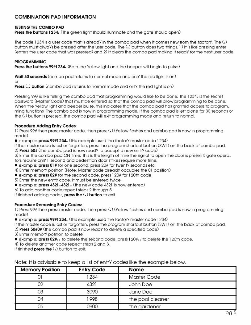
Memory Position Entry Code Name0102030405
12344321309019980900
Master CodeJohn DoeJane Doethe pool cleanerthe gardener
Note: It is advisable to keep a list of entry codes like the example below.
COMBINATION PAD INFORMATION
TESTING THE COMBO PADPress the buttons 1234* (The green light should illuminate and the gate should open)
The code 1234 is a user code that is already in the combo pad when it comes new from the factory. The (*)button must always be pressed after the user code. The (*) button does two things. 1) It is like pressing enter(enters the user code that was pressed) and 2) It clears the combo pad making it ready for the next user code.
PROGRAMMINGPress the buttons 99#1234* (Both the yellow light and the beeper will begin to pulse)
Wait 30 seconds (combo pad returns to normal mode and only the red light is on)orPress (*) button (combo pad returns to normal mode and only the red light is on)
Pressing 99# is like telling the combo pad that programming would like to be done. The 1234* is the secretpassword (Master Code) that must be entered so that the combo pad will allow programming to be done.When the yellow light and beeper pulse, this indicates that the combo pad has granted access to program-ming functions. The combo pad is now in programming mode. If the combo pad is left alone for 30 seconds orthe (*) button is pressed, the combo pad will exit programming mode and return to normal.
Procedure Adding Entry Codes:1) Press 99# then press master code, then press (*) (yellow flashes and combo pad is now in programmingmode)l example: press 99#1234* (this example used the factory master code 1234)If the master code is lost or forgotten, press the program shortcut button (SW1) on the back of combo pad.2) Press 50# (the combo pad is now ready to accept a new entry code)3) Enter the combo pad ON time. This is the length of time the signal to open the door is present) gate opera-tors require only 1 second and pedestrian door strikes require more time.l example: press 01# for one second, press 20# for twenty seconds etc.4) Enter memory position (Note: Master code already occupies the 01 position)l example: press 02# for the second code, press 120# for 120th code5) Enter the new entry code. It must be entered twice.l example: press 4321*4321* (the new code 4321 is now entered)6) To add another code repeat steps 2 through 5.If finished adding codes, press the (*) button to exit
Procedure Removing Entry Codes:1) Press 99# then press master code, then press (*) (yellow flashes and combo pad is now in programmingmode)l example: press 99#1234* (this example used the factory master code 1234)If the master code is lost or forgotten, press the program shortcut button (SW1) on the back of combo pad.2) Press 50#0# (the combo pad is now ready to delete a specified code)3) Enter memory position to delete.l example: press 02#** to delete the second code, press 120#** to delete the 120th code.4) To delete another code repeat steps 2 and 3.If finished press the (*) button to exit.
pg 6
Procedure Adding/Changing Master Code:1) Press 99# then press master code, then press (*) (yellow flashes and combo pad is now in programmingmode)l example: press 99#1234* (this example used the factory master code 1234)If the master code is lost or forgotten, press the program shortcut button (SW1) on the back of combo pad.2) Press 50# (the combo pad is now ready to accept a new master code)3) Enter the combo pad ON timel example: press 01# for one second, press 20# for twenty seconds etc.4) Enter memory position press 01#5) Enter the new master code. It must be entered twice.l example: press 5678*5678* (the new master code 5678 is now entered)6) The new master code will now need to be used to do any programming and should be written down. In-stead of entering 99#1234* as done previously the user must press 99#CODE* to enter programming mode or asin the example above press 99#5678*
ADVANCED PROGRAMMING
Procedure Adding Hold Open Codes Codes:1) Press 99# then press master code, then press (*) (yellow flashes and combo pad is now in programmingmode)l example: press 99#1234* (this example used the factory master code 1234)If the master code is lost or forgotten, press the program shortcut button (SW1) on the back of combo pad.2) Press 50# (the combo pad is now ready to accept a new entry code)3) Enter the combo pad ON time. This is the length of time the signal to open the door is present) for a holdopen code, this time should be set to zero.l example: press 00# for zero seconds4) Enter memory position (Note: Master code already occupies the 01 position)l example: press 03# for the third code, press 120# for 120th code5) Enter the new entry code. It must be entered twice.l example: press 3090*3090* (the new code 3090 is now entered)6) To add another code repeat steps 2 through 5.
Procedure Erasing Entire Combo Pad Memory1) Press 99# then press master code, then press (*) (yellow flashes and combo pad is now in programmingmode)l example: press 99#1234* (this example used the factory master code 1234)If the master code is lost or forgotten, press the program shortcut button (SW1) on the back of combo pad.2) Press 46#00000#00000#** (this erases contents of memory)Note: This procedure also erases the master code (refer to procedure for adding a new master code)
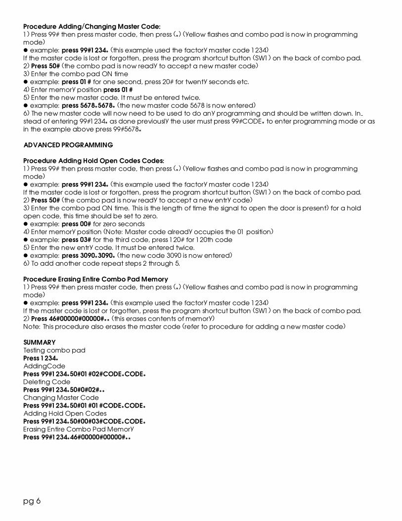
SUMMARYTesting combo padPress 1234*AddingCodePress 99#1234*50#01#02#CODE*CODE*Deleting CodePress 99#1234*50#0#02#**Changing Master CodePress 99#1234*50#01#01#CODE*CODE*Adding Hold Open CodesPress 99#1234*50#00#03#CODE*CODE*Erasing Entire Combo Pad MemoryPress 99#1234*46#00000#00000#**
pg 7
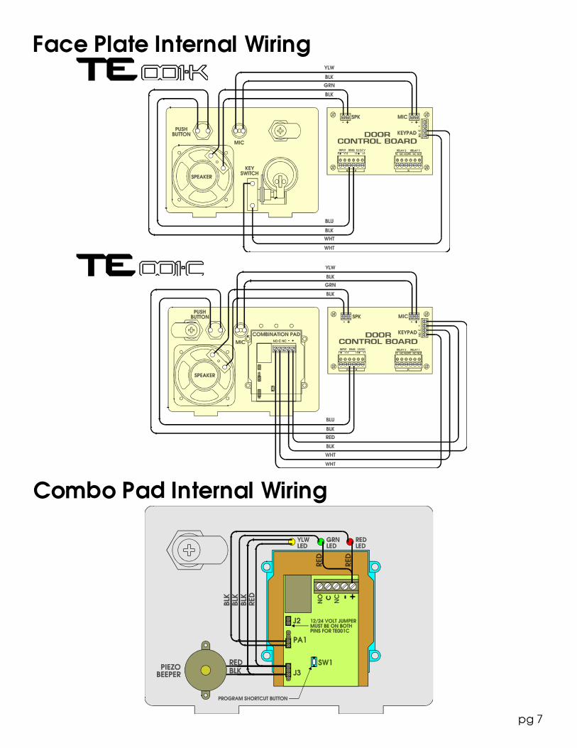
Face Plate Internal Wiring
Combo Pad Internal Wiring

pg 8