telescopic bottle jack … · · 2017-05-02keep these instructions for future reference. ... this...
TRANSCRIPT

TELESCOPIC BOTTLE JACKMODEL NO: CTBJ5, 10 & 12
PART NO: 7621037, 7621050 & 7621795
OPERATION AND MAINTENANCE
GC1016
INSTRUCTIONS
P
INTRODUCTION
Thank you for purchasing this CLARKE Bottle Jack.
Before attempting to use this product, please read this manual thoroughly and follow the instructions carefully. In doing so you will ensure the safety of yourself and that of others around you, and you can look forward to your purchase giving you long and satisfactory service.
Keep these instructions for future reference.
GUARANTEE
This product is guaranteed against faulty manufacture for a period of 12 months from the date of purchase. Please keep your receipt which will be required as proof of purchase.
This guarantee is invalid if the product is found to have been abused or tampered with in any way, or not used for the purpose for which it was intended.
Faulty goods should be returned to their place of purchase, no product can be returned to us without prior permission.
This guarantee does not effect your statutory rights.
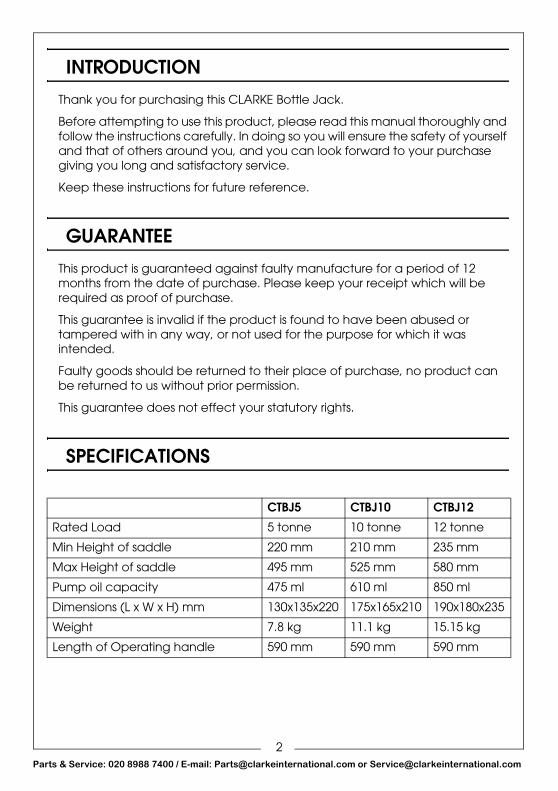
SPECIFICATIONS
CTBJ5 CTBJ10 CTBJ12
Rated Load 5 tonne 10 tonne 12 tonne
Min Height of saddle 220 mm 210 mm 235 mm
Max Height of saddle 495 mm 525 mm 580 mm
Pump oil capacity 475 ml 610 ml 850 ml
Dimensions (L x W x H) mm 130x135x220 175x165x210 190x180x235
Weight 7.8 kg 11.1 kg 15.15 kg
Length of Operating handle 590 mm 590 mm 590 mm
2arts & Service: 020 8988 7400 / E-mail: [email protected] or [email protected]

P
SAFETY PRECAUTIONS
1. Do not exceed the rated capacity of the jack.
2. Do not allow personnel to operate the jack unless they have read these safety precautions.
3. Do not operate the jack if damaged.
4. Use the jack in a suitable, well lit work area.
5. Keep the work area clean and tidy and free from unrelated items.
6. Only use the jack on level and solid ground, preferably concrete. Avoid soft/unmade ground as the jack may sink in.
7. Ensure non-essential persons keep a safe distance whilst the jack is in use.
8. Ensure there are no personnel or obstructions under the vehicle before lowering.
9. Do not work under the vehicle until it is fully supported by axle stands.
10. Keep hands etc clear of the vehicle until lifting is complete.
11. Ensure that you can see the saddle and jacking point throughout the jacking operation in case there is any relative movement.
12. Always ensure that the jack saddle is centred and stable on the lifting point before lifting and position the jack to avoid operating it from under the vehicle.
13. Check the vehicle weight and recommended lifting points by referring to the vehicle owners manual. Ensure the lifting point is not corroded.
14. Never tamper with the jack or modify it in any way, as this could prove to be dangerous and will invalidate the guarantee. Only use the jack for the purpose for which it is intended.
15. Use appropriate safety equipment, such as protective footwear, when using this jack.
16. Ensure that the jack is properly maintained and lubricated at all times, and that no corrosion is allowed to weaken any part of it.
17. If the jack has been subjected to an abnormal load or shock, it should be removed from service immediately and fully inspected by qualified personnel, and passed as serviceable, before being used again.
18. When not in use, store the jack, fully lowered, in a safe, dry, childproof area.
19. Always inspect the jack before use. Ensure that all parts are in good condition and operating smoothly, and that no cracks or distortion is apparent. If in doubt do not use.
3arts & Service: 020 8988 7400 / E-mail: [email protected] or [email protected]

P
20. Never push a vehicle off the jack or start the engine while supported only by the jack.
21. Do not use if an oil leak is apparent. Consult the Clarke Service Department.
22. If more than one jack is used in unison, they must all be of the same rating and be raised at the same speed to reduce the possibility of the load slipping.
SAFETY SYMBOLSThe following safety symbols may be found on the product.
Read the user manual before use.
LIFTING OPERATIONS AND LIFTING EQUIPMENT REGULATIONS 1998This jack, depending on use, may fall within the scope of LOLER. It is the owner’s responsibility to determine whether or not it does and, if so, to comply with any applicable requirements in LOLER, for having the jack thoroughly examined.
ENVIRONMENTAL PROTECTION1. Take care to ensure that if hydraulic oil is spilt that it is cleaned away using
sand or treated with absorbent granules designed for the purpose.
2. Always make every effort to contain any spillage and prevent ingress into the local water course.
4arts & Service: 020 8988 7400 / E-mail: [email protected] or [email protected]

P
PRODUCT FEATURES
(CTBJ12 shown)
UNPACKINGDuring transit or storage, it is possible that an air pocket may have developed within the hydraulic ram, and the ram action may therefore appear to be ‘spongy’. In this case the jack may require purging as described on page 7.
If the column does not reach its full height, the ram oil level may require topping up, as described in the Maintenance section.
1 3 x Handle Tubes
2 Ram
3 Screw Extension
4 Oil Filler Plug
5 Actuating Lever
6 Release Valve
5arts & Service: 020 8988 7400 / E-mail: [email protected] or [email protected]

P
OPERATION
RAISING A VEHICLE1. Ensure the vehicle is stable and is on firm level ground with the wheels
chocked before positioning the jack so that is directly beneath the lifting point. DO NOT rely upon the vehicle handbrake alone to prevent vehicle movement.
2. Ensure the jack is on solid ground. If not, place a suitable piece of solid wood of sufficient size to provide adequate support beneath the jack.
3. Consult the vehicle owners manual to ascertain the location of suitable jacking points and position the jack beneath the designated lifting point.
4. Locate the slotted end of the jack handle on to the release valve and turn fully clockwise to close the valve.
5. Set the screw extension (CTB10 & 12 models) in contact with the lifting point. Pump the handle and raise the ram so that the jack and lifting point are in full contact. Before proceeding further, make one final check to ensure that:
• the jack is completely vertical and stable.
• there are no obstructions to the lift and that the handle can move freely up and down.
• all personnel are in a safe position.
6. When satisfied, continue to pump the handle and lift the load to the height required.
7. NEVER allow anyone to get beneath the load until it is firmly supported on suitable, properly rated axle stands.
LOWERING THE VEHICLE
1. The lowering speed is controlled by the amount you turn the release valve. With the axle stands removed, check to ensure that there are no personnel
WARNING: ENSURE THE SAFETY PRECAUTIONS ARE STRICTLY FOLLOWED. NO RESPONSIBILITY CAN BE ACCEPTED FOR INCORRECT USE OF THE JACK
WARNING: ALWAYS LOWER IN A SLOW AND CONTROLLED MANNER, AND CHECK THAT THERE ARE NO OBSTACLES IN THE PATH OF THE LOAD’S DESCENT. BE EXTREMELY CAREFUL WHEN LOWERING HEAVY LOADS.
6arts & Service: 020 8988 7400 / E-mail: [email protected] or [email protected]

P
in the immediate vicinity before removing the handle from its housing, and engaging it with the release valve.
2. Very slowly turn the handle anticlockwise to open the release valve, and allow the jack to lower the load, under complete control. NEVER, under any circumstances, jerk the valve open.
MAINTENANCE
IMPORTANT: Only fully qualified personnel should attempt to repair the jack.
INSPECTION1. Always visually inspect the jack before use, to ensure that all parts are
correctly located and secure. Check for hydraulic leaks, signs of damage or worn parts. Do not use the jack unless it is perfectly serviceable.
• A slight dampness on the ram is normal, but where leakage is found, the ram seals must be renewed by your Clarke Spares Department.
2. The jack should be fully inspected annually as follows:
• Check for cracks and deformation of components.
• Check operation and top up the oil level. (see below).
• Remove completely, any rust or corrosion and repaint to prevent further corrosion.
• Ensure that all decals and warning notices are in place and legible.
3. After use, store the jack with the ram in its lowest position. This not only relieves the hydraulic ram, but also prevents any possibility of corrosion to the ram.
4. Do not leave the jack in the open, exposed to the weather. Keep under cover. If stored for long periods, inspect before use, clean, and re-oil. For servicing, contact your CLARKE dealer or CLARKE Service dept.
TOPPING UP THE OILIt may be necessary from time to time to top up the hydraulic oil level. Proceed as follows.
1. Turn the release valve counterclockwise and allow the ram to retract to its lowest position.
• It may be necessary to apply force to the saddle for lowering without any weight on the jack.
2. With the jack in the level position, remove the filler plug and stand upright.
• The oil should be level with the bottom of the oil filler hole.
7arts & Service: 020 8988 7400 / E-mail: [email protected] or [email protected]

P
3. If below this, top up.
4. Do not overfill. Only use the correct type of oil such as Clarke hydraulic oil (part number 3050830).
5. Replace the filler plug.
6. Check the jack for correct operation and purge any air from the system as described below.
PURGING AIR FROM THE JACK1. Turn the release valve counterclockwise one full turn to open.
2. Pump the handle eight full strokes.
3. Turn the release valve clockwise to close the valve.
4. Pump the handle until the ram reaches maximum height and continue to pump several times to remove trapped air.
5. Turn the release valve counterclockwise one full turn and lower the ram to its lowest position. Apply pressure if necessary.
6. Turn the release valve clockwise to the closed position and check for correct operation. It may be necessary to perform the procedure more than once to evacuate all the air.
TROUBLESHOOTING
Problem Check SolutionJack will not lift to full height
Low oil level Check oil level
Jack will not hold load Release valve not closingHydraulic oil contaminatedPump valves not sealingCylinder ram binding
Contact Clarke Service Department
Jack piston will not lower
Cylinder ram bindingParts warnInternal damageBroken or disconnected return springLift arm linkage bent or binding
Contact Clarke Service Department
Jack feels spongy when lifting
See Air Purging section See air purging procedure above
8arts & Service: 020 8988 7400 / E-mail: [email protected] or [email protected]
P
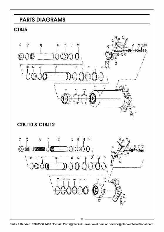
PARTS DIAGRAMS
CTBJ5
CTBJ10 & CTBJ12
9arts & Service: 020 8988 7400 / E-mail: [email protected] or [email protected]
P
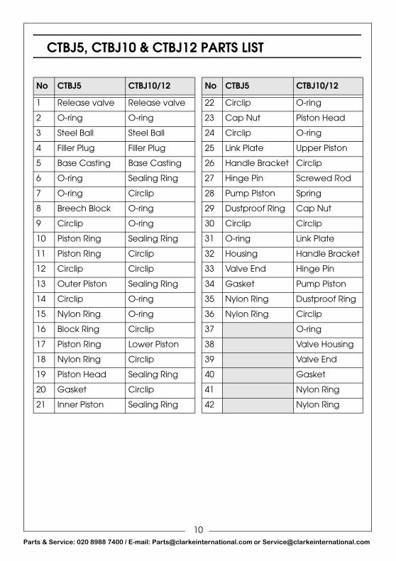
CTBJ5, CTBJ10 & CTBJ12 PARTS LIST
No CTBJ5 CTBJ10/12 No CTBJ5 CTBJ10/12
1 Release valve Release valve 22 Circlip O-ring
2 O-ring O-ring 23 Cap Nut Piston Head
3 Steel Ball Steel Ball 24 Circlip O-ring
4 Filler Plug Filler Plug 25 Link Plate Upper Piston
5 Base Casting Base Casting 26 Handle Bracket Circlip
6 O-ring Sealing Ring 27 Hinge Pin Screwed Rod
7 O-ring Circlip 28 Pump Piston Spring
8 Breech Block O-ring 29 Dustproof Ring Cap Nut
9 Circlip O-ring 30 Circlip Circlip
10 Piston Ring Sealing Ring 31 O-ring Link Plate
11 Piston Ring Circlip 32 Housing Handle Bracket
12 Circlip Circlip 33 Valve End Hinge Pin
13 Outer Piston Sealing Ring 34 Gasket Pump Piston
14 Circlip O-ring 35 Nylon Ring Dustproof Ring
15 Nylon Ring O-ring 36 Nylon Ring Circlip
16 Block Ring Circlip 37 O-ring
17 Piston Ring Lower Piston 38 Valve Housing
18 Nylon Ring Circlip 39 Valve End
19 Piston Head Sealing Ring 40 Gasket
20 Gasket Circlip 41 Nylon Ring
21 Inner Piston Sealing Ring 42 Nylon Ring
10arts & Service: 020 8988 7400 / E-mail: [email protected] or [email protected]
P
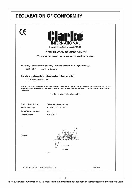
DECLARATION OF CONFORMITY
11arts & Service: 020 8988 7400 / E-mail: [email protected] or [email protected]