televideo® model 910 crt terminal installation and user's ... · pdf...
TRANSCRIPT

TeleVideo® Model 910 CRT Terminal Installation and User's Guide
10
o® Televideo Systems, Inc.
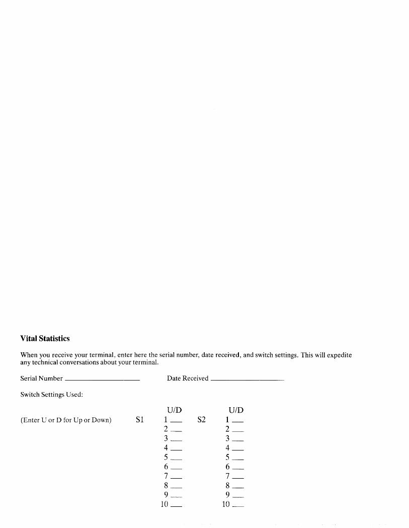
Vital Statistics
When you receive your terminal, enter here the serial number, date received, and switch settings. This will expedite any technical conversations about your terminal.
Serial Number ________ _ Date Received ________ _
Switch Settings Used:
U/D U/D (Enter U or D for Up or Down) Sl 1_ S2 1_
2_ 2_ 3_ 3_ 4_ 4_ 5_ 5_ 6_ 6_ 7_ 7_ 8_ 8_ 9_ 9_ la_ ID_

MODEL 910 OPERATOR'S MANUAL Tele Video® No. 2002500 Revision D Copyright Tele Video Systems, Inc.
April 1983
Copyright © 1983 by Tele Video Systems, Inc. All rights reserved. No part of this publication may be reproduced, transmitted, transcribed, stored in a retrieval system, or translated into any language or computer language, in any form or by any means, electronic, mechanical, magnetic, optical, chemical, manual, or otherwise, without the prior written permission of TeleVideo Systems, Inc., 1170 Morse Avenue, Sunnyvale, California 94086.
Disclaimer
TeleVideo Systems, Inc. makes no representations or warranties with respect to this manual. Further, TeleVideo Systems, Inc. reserves the right to make changes in the specifications of the product described within this manual at any time without notice and without obligation of Tele Video Systems, Inc. to notify any person of such revision or changes.
For terminals shipped before October 1, 1983, the following statement applies:
"Warning: This equipment generates, uses, and can radiate radio frequency energy, and if not insblled and used in accordance with the instruction manual may cause interference to radio communications. As temporarily permitted by regulation, it has not been tested for compliance with the limits for Class A computing devices pursuant to Subpart J of Part 15 of FCC Rules, which are designed to provide reasonable protection against such interference. Operation of this equipment in a residential area is likely to cause interference, in which case the user at his own expense will be required to correct the interference."
For terminals shipped after October 1, 1983, the following statement applies:
"Warning: This equipment generates, uses, and can radiate radio frequency energy, and if not installed and used in accordance with the instruction manual may cause interference to radio communications. It has been tested and found to comply with the limits for a Class A computing device pursuant to Subpart J of Part 15 of the FCC Rules, which are designed to provide reasonable protection against such interference when operated in .a commercial enviro~ment. Operation of this equipment in a residential area is likely to cause interference, in whIch case the user at hIS own expense will be required to correct the interference."
Tele Video® is a registered trademark of Tele Video Systems, Inc.
TELEVIDEO SYSTEMS, INC., 1170 Morse Avenue, Sunnyvale, California 94086 408/745-7760

STATEMENT OF LIMITED WARRANTY
Tele Video Systems, Inc. ("Tele Video") warrants to Buyer that products, except software, manufactured by Tele Video will be free from defects in material and workmanship. TeleVideo's obligations under this warranty will be limted to repairing or replacing, at TeleVideo's option, the part or parts of the products which prove defective in material or workmanship within 90 days after shipment by TeleVideo, provided that Buyer gives TeleVideo prompt notice of any defect and satisfactory proof thereof. Products may be returned by Buyer only after a Return Material Authorization number ("RMA") has been obtained from Te1eVideo by telephone or in writing. Buyer will prepay all freight charges to return any products to the repair facility designated by Te1e Video and include the RMA number on the shipping container. Tele Video will deliver replacements for defective products or parts on an exchange basis to Buyer, freight prepaid to the Buyer. Products returned to TeleVideo under this warranty will become the property of TeleVideo. With respect to any product or part thereof not manufactured by TeleVideo, only the warranty, if any, given by the manufacturer thereof, will apply.
Exclusions
This limited warranty does not cover losses or damage which occurs in shipment to or from Buyer, or is due to (1) improper installation or maintenance, misuse, neglect, or any cause other than ordinary commercial or industrial application or (2) adjustment, repair or modifications by other than TeleVideo-authorized personnel or (3) improper environment, excessive or inadequate heating or air conditioning, and electrical power failures, surges or other irregularities or (4) any statements made about TeleVideo's products by salesmen, dealers, distributors or agents, unless confirmed in writing by a Tele Video officer.
THE FOREGOING TELEVIDEO LIMITED WARRANTY IS IN LIEU OF ALL OTHER WARRANTIES, WHETHER ORAL, WRITTEN, EXPRESS, IMPLIED OR STATUTORY. IMPLIED WARRANTIES OF MERCHANTABILITY AND FITNESS FOR A PARTICULAR PURPOSE WILL NOT APPLY. TELEVIDEO'S WARRANTY OBLIGATIONS AND BUYER'S REMEDIES HEREUNDER ARE SOLELY AND EXCLUSIVELY AS STATED HEREIN. TELEVIDEO MAKES NO WARRANTY WHATSOEVER CONCERNING ANY SOFTWARE PRODUCTS, WHICH ARE SOLD "AS IS" AND "WITH ALL FAULTS."
TELEVIDEO'S LIABILITY, WHETHER BASED ON CONTRACT, TORT, WARRANTY, STRICT LIABILITY OR ANY OTHER THEORY, SHALL NOT EXCEED THE PRICE OF THE INDIVIDUAL UNIT WHOSE DEFECT OR DAMAGE IS THE BASIS OF THE CLAIM. IN NO EVENT SHALL TELEVIDEO BE LIABLE FOR ANY LOSS OF PROFITS, LOSS OF USE OF FACILITIES OR EQUIPMENT, OR OTHER INDIRECT, INCIDENTAL OR CONSEQUENTIAL DAMAGES.
Service Out of Warranty
If your terminal is out of warranty when it needs service, you should follow the same procedure to receive an RMA. You will be responsible for all shipping costs.
Should your company require a purchase order for out-of-warranty repairs, let us know the purchase order number when you call in. One purchase order may cover several repairs but we will give each item its own individual RMA number. This allows us to return each item quickly and not hold up the entire purchase order because of one item.
Technical Assistance
The Service Department is normally open from 8:00 a.m. until 5:00 p.m., Pacific Time, Monday through Friday. If the line is busy and your problem can wait, leave a message with theTe1e Video operator and your call will be returned at our first opportunity.
Extended Warranty
Tele Video offers an Extended Warranty Contract. To take advantage of this Extended Warranty, you must sign an Extended Warranty Contract and return it, together with full payment, to TeleVideo prior to the end of your normal warranty period. The extended warranty lasts for one year; the cost is $75.00. Call our Terminal Division Literature Department (4081745-7760) for a contract.
To renew the extended warranty for another year, the same procedure must followed.
Shipping charges are not included in the Extended Warranty. This is the only expense you incur.
ii
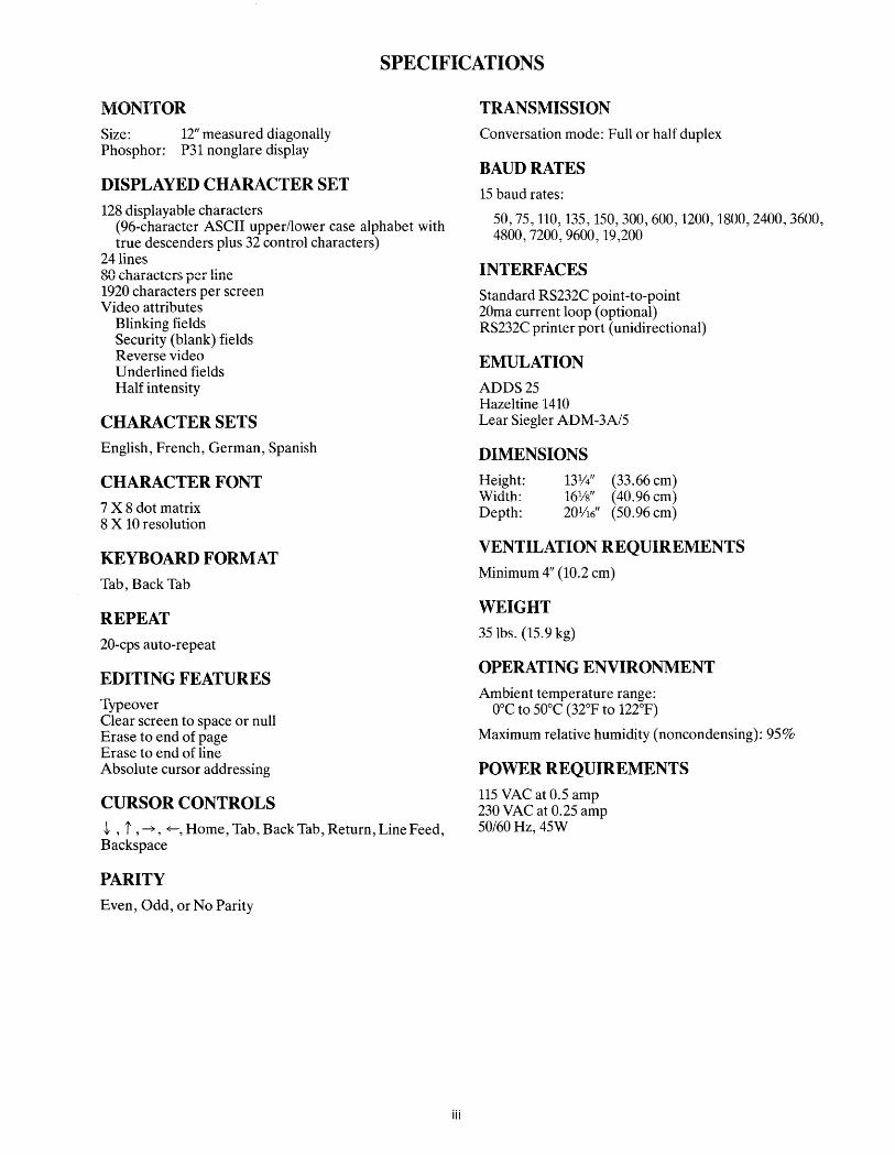
SPECIFICATIONS
MONITOR Size: 12" measured diagonally Phosphor: P31 nonglare display
DISPLAYED CHARACTER SET 128 displayable characters
(96-character ASCII upper/lower case alphabet with true descenders plus 32 control characters)
24 lines 80 characters per line 1920 characters per screen Video attributes
Blinking fields Security (blank) fields Reverse video Underlined fields Half intensity
CHARACTER SETS English, French, German, Spanish
CHARACTER FONT 7 X 8 dot matrix 8 X 10 resolution
KEYBOARD FORMAT Tab, Back Tab
REPEAT 20-cps auto-repeat
EDITING FEATURES Typeover Clear screen to space or null Erase to end of page Erase to end of line Absolute cursor addressing
CURSOR CONTROLS t , i ,~, ~, Home, Tab, Back Tab, Return, Line Feed Backspace '
PARITY Even, Odd, or No Parity
iii
TRANSMISSION Conversation mode: Full or half duplex
BAUD RATES 15 baud rates:
50,75,110,135,150,300,600,1200,1800,2400 3600 4800,7200,9600,19,200 ' ,
INTERFACES Standard RS232C point-to-point 20m a current loop (optional) RS232C printer port (unidirectional)
EMULATION ADDS 25 Hazeltine 1410 Lear Siegler ADM-3A/5
DIMENSIONS Height: Width: Depth:
13%" (33.66 cm) 16%" (40.96 cm) 201/16" (50.96 cm)
VENTILATION REQUIREMENTS Minimum 4" (10.2 cm)
WEIGHT 351bs. (15.9 kg)
OPERATING ENVIRONMENT Ambient temperature range:
O°C to 50°C (32°F to 122°F)
Maximum relative humidity (noncondensing): 95%
POWER REQUIREMENTS 115 VAC at 0.5 amp 230 VAC at 0.25 amp 50/60 Hz, 45W

TABLE OF CONTENTS
STATEMENT OF LIMITED WARRANTY, TECHNICAL ASSISTANCE . . . . . . . . . . . . . .. ii
SPECIFICATIONS . ....................... iii
1. INTRODUCTION . .................... " 1 Description of Manual . . . . . . . . . . . . . . . . . . .. 1 How to Use This Manual . . . . . . . . . . . . . . . . .. 1 Description of Terminal . . . . . . . . . . . . . . . . . .. 1 Protect Yourself! . . . . . . . . . . . . . . . . . . . . . . .. 1 Protect the Terminal ..................... 2
2. INSTALLATION. . . . . . . . . . . . . . . . . . . . . . .. 2 Introduction ........................... 2 Unpacking and Inspecting the Terminal ....... 2 Preparing the Site ....................... 3 Installation ............................ 3 Checking Your Installation ................ 8
3. OPERATION... . . . . . . . . . . . . . . . . . . . . . . .. 8 Introduction ........................... 8 Turning on the Terminal .................. 8 Keyboard Controls ...................... 9 Basic Operations ........................ 12
4. PROGRAMMING ....... ................ 12 Introduction ........................... 12 Monitoring Control Commands ............. 13 Control Functions ....................... 13 FUNCT Key ........................... 13 Addressing the Cursor .................... 13 Auto Scroll ............................ 14 Visual Attributes ........................ 14 Enabling/Disabling the Printer ............. 14 Disabling the Keyboard ................... 15 Word Structure, Parity Settings, and Stop Bits .15 Custom RAM and ROM Applications ........ 16 Cursor Appearance/Disappearance .......... 16 Bell .................................. 16
5. PREVENTIVE MAINTENANCE ........... 16 Care ................................. 16
6. TROUBLESHOOTING AND REPAIR ....... 16 Troubleshooting ......................... 16 Repair ................................ 17
APPENDICES A. Summary of Functional Commands ....... 21 B. Cursor Coordinates . . . . . . . . . . . . . . ..... 24 C. ADDS Cursor Coordinates ............. 25 D. ASCII Code Chart .................... 25
INDEX .................................. . 26
GLOSSARY ........................... , .. 27
iv
OPERATOR'S QUICK REFERENCE GUIDE
TABLES Table 2-1-P3 (Computer Interface) Connector ..... 3 Table 2-2-Serial Interface (P4) Pin Connections
(Printer) ...... , ... , . , ........... , , .. , . . .. 3 Table 2-3-SwitchSettings for Model 910 , , . , .. , . " 4 Table 2-4-Switch Settings of SI for Common Word
Structures ....................... , . . . . . . .. 7 Table 2-5-RS232C Terminal Interface Jumper
Options ... , , .. , ........................ '. 5 Table 2-6-Character Set Jumper Options . . . . . . . .. 8 Table 2-7-Composite Video Jumper Option ...... 8 Table 3-1-Function of Keys ................... 10 Table 4-1-Function Key Commands ............. 13 Table 4-2-Escape Sequences for Visual Attributes .. 14 Table 4-3-Switch Settings for Parity and Data Bits .. 16 Table 6-1-Troubleshooting Terminal Problems ..... 18 Table A-I-Summary of Functional Commands .... 21 Table B-I-Cursor Coordinates ................. 24 Table C-I-ADDS Cursor Coordinates ........... 25 Table D-I-ASCII Code Chart ................. 25
FIGURES
Figure 2-1-Model 910 Dimensions . . . . . . . . . . . . .. 4 Figure 2-2-Rear Panel ' .. '................... .. Figure 2-3- TTL Logic Board . . . . . . . . . . . . . . . . .. ~ Figure 2-4- Gate Array Logic Board ........... , 6 Figur~ 2-5-Switch Setting Examples ..... , . . . . . .. 7 Figure 3-1-Model 910 Keyboard Layout ......... 9 Figure 3-2-Model 910 Communications Flow. , . . .. 9 Figure 4-1-Model 910 Video Attributes and Monitor
Mode ............................... , ... 15 Figure 4-2-Bit Structure of a Serial Data Word .... 16

1. INTRODUCTION
1 DESCRIPTION OF MANUAL
This manual will teach you how to install, operate, program, and troubleshoot your new terminal. The manual has been designed to help you use the terminal easily regardless of your previous experience with terminals. As you progress through the manual, you will find the following chapters:
2e Installation Setting up your site for the terminal, the power requirements, unpacking and checking the terminal, setting switches to take advantage of the options available, configuring the terminal for your computer system and printer.
3. Operation Turning on the terminal, a description of the keyboard and functions of the keys, using tabs, editing, sending data to the computer and the printer.
4. Programming Controlling the terminal through commands from your computer system: programming special functions, setting visual attributes, monitoring the program, loading and reading the cursor position, adding custom RA~1 'md ROM, using Auto Scroll, disabling the keyboard .nd printer.
5. Preventive Maintenance Periodic cleaning and inspection of the terminal.
6. Troubleshooting and Repair Troubleshooting simple problems (using a table of symptoms, possible causes, and solutions), using self-test.
Glossary Explanation of terms commonly used in this manual.
Appendices Reference tables.
Index References to main subsections by subject.
1.2 HOW TO USE THIS MANUAL
Each subsection of the manual is numbered. To find a topic later, look in the index and find the appropriate 'ubsection.
As you read the manual, you will notice some special symbols at the left margin of the text. These symbols call your attention to information of special importance. The symbols used are:
1
<::1' ~~~"I1IIII::::J1
8
General note giving information to every operator.
Programming note giving information of special significance to the programmer.
Warning giving information concerning the safety of the operator or possible loss of data. When you see this note, STOP and read the note before proceeding!
Emulation commands are given in Table A-I and the Operator's Quick Reference Guide. The descriptive text of the manual will only reference the 910 commands.
On the back cover is the Operator's Quick Reference Guide, listing all control and escape commands for the terminal.
1.3 DESCRIPTION OF TERMINAL
A brief overview of the capabilities of your terminal will help you take advantage of its features as you use it. The Model 910 operates in a conversation mode with your computer system, in either half or full duplex. Baud rates can be set at any of 15 speeds, from 50 to 19,200.
Depending on switch settings, the 910 will emulate a Lear Siegler ADM-3A/5, a Hazeltine 1410, or an ADDS 25. Character sets can be changed to English, Spanish, German, or French. Visual attributes can be set a line at a time, either alone or in combination. You can set the display to monitor the computer program (to facilitate program debugging).
Printing is easily controlled with a special PRINT key. Using the FUNCT key with a numeric key allows you to quickly transmit one of ten special command code sequences. To create custom applications, you ~an easily substitute a ROM with twice as much space. Termination characters are switch selectable. The keyboard is a Selectric style and includes a ten-key pad for easy entry of numbers.
1.4 PROTECT YOURSELF!
When you install or test the terminal, observe standard safety precautions (as you would with any electrical or electronic equipment). Only qualified service personnel should open the terminal housing. Disconnect all power before performing any inspection or maintenance.
8 Beyond the normal precautions, you should be aware of two additional conditions:
1. If the CRT tube should be broken, always wear heavy rubber gloves or use tongs to pick up the broken CRT fragments since the coating on the inside of the tube is poisonous.
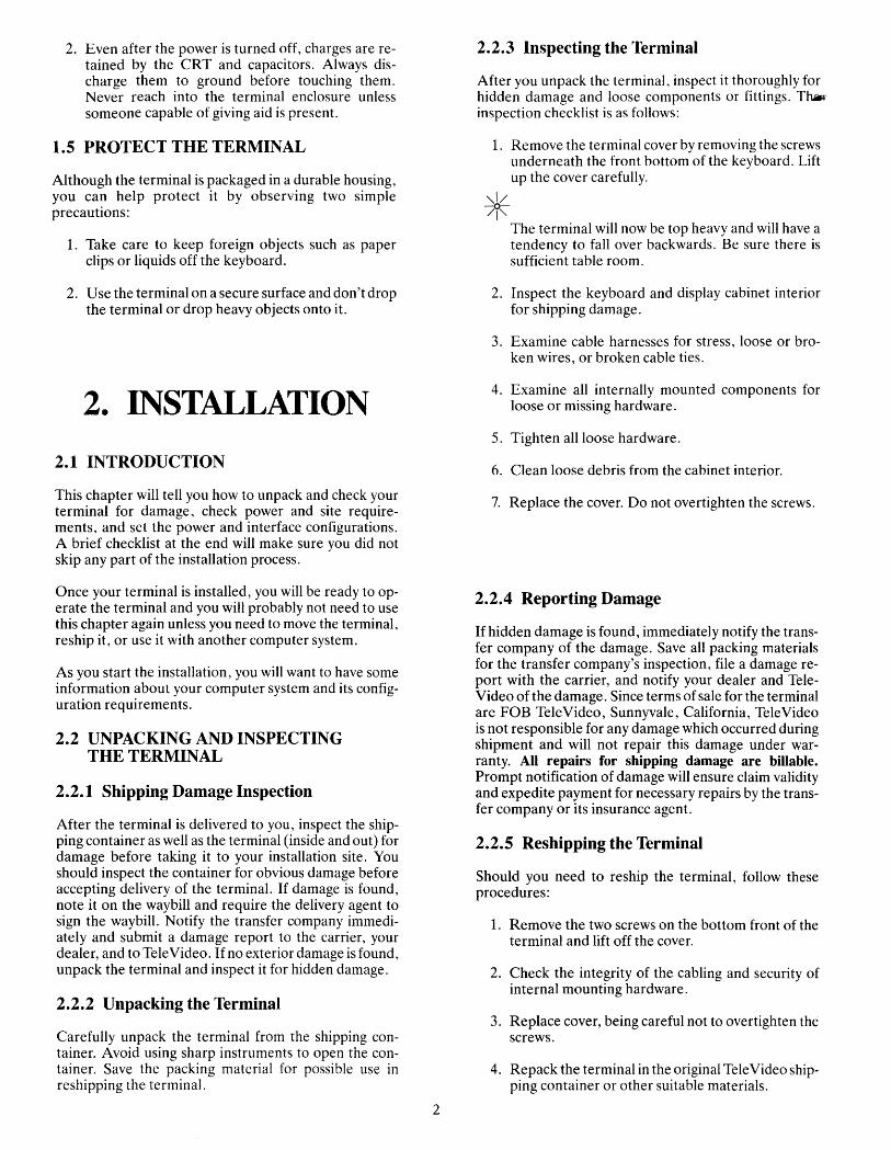
2. Even after the power is turned off, charges are retained by the CRT and capacitors. Always discharge them to ground before touching them. Never reach into the terminal enclosure unless someone capable of giving aid is present.
1.5 PROTECT THE TERMINAL
Although the terminal is packaged in a durable housing, you can help protect it by observing two simple precautions:
1. Take care to keep foreign objects such as paper clips or liquids off the keyboard.
2. Use the terminal on a secure surface and don't drop the terminal or drop heavy objects onto it.
2. INSTALLATION
2.1 INTRODUCTION
This chapter will tell you how to unpack and check your terminal for damage, check power and site requirements, and set the power and interface configurations. A brief checklist at the end will make sure you did not skip any part of the installation process.
Once your terminal is installed, you will be ready to operate the terminal and you will probably not need to use this chapter again unless you need to move the terminal, reship it, or use it with another computer system.
As you start the installation, you will want to have some information about your computer system and its configuration requirements.
2.2 UNPACKING AND INSPECTING THE TERMINAL
2.2.1 Shipping Damage Inspection
After the terminal is delivered to you, inspect the shipping container as well as the terminal (inside and out) for damage before taking it to your installation site. You should inspect the container for obvious damage before accepting delivery of the terminal. If damage is found, note it on the waybill and require the delivery agent to sign the waybill. Notify the transfer company immediately and submit a damage report to the carrier, your dealer, and to TeleVideo. If no exterior damage is found, unpack the terminal and inspect it for hidden damage.
2.2.2 Unpacking the Terminal
Carefully unpack the terminal from the shipping container. Avoid using sharp instruments to open the container. Save the packing material for possible use in reshipping the terminal.
2
2.2.3 Inspecting the Terminal
After you unpack the terminal, inspect it thoroughly for hidden damage and loose components or fittings. Th.Ji.r inspection checklist is as follows:
1. Remove the terminal cover by removing the screws underneath the front bottom of the keyboard. Lift up the cover carefully.
,,1/ -0-/1"
The terminal will now be top heavy and will have a tendency to fall over backwards. Be sure there is sufficient table room.
2. Inspect the keyboard and display cabinet interior for shipping damage.
3. Examine cable harnesses for stress, loose or broken wires, or broken cable ties.
4. Examine all internally mounted components for loose or missing hardware.
5. Tighten all loose hardware.
6. Clean loose debris from the cabinet interior.
7. Replace the cover. Do not overtighten the screws.
2.2.4 Reporting Damage
If hidden damage is found, immediately notify the transfer company of the damage. Save all packing materials for the transfer company's inspection, file a damage report with the carrier, and notify your dealer and TeleVideo of the damage. Since terms of sale for the terminal are FOB TeleVideo, Sunnyvale, California, TeleVideo is not responsible for any damage which occurred during shipment and will not repair this damage under warranty. All repairs for shipping damage are billable. Prompt notification of damage will ensure claim validity and expedite payment for necessary repairs by the transfer company or its insurance agent.
2.2.5 Reshipping the Terminal
Should you need to reship the terminal, follow these procedures:
1. Remove the two screws on the bottom front of the terminal and lift off the cover.
2. Check the integrity of the cabling and security of internal mounting hardware.
3. Replace cover, being careful not to overtighten the screws.
4. Repack the terminal in the original Tele Video shipping container or other suitable materials.

2.3 PREPARING THE SITE
Before you proceed with the actual installation, make < ~,ure you are ready with the proper power and a large
. lough table.
2.3.1 Power Requirements
• 115 VAC 60 Hertz at 0.5 amp OR
230 VAC 50 Hertz at 0.25 amp
• 45 watts
• NEMA standard 5-15R, 3-prong receptable (US only)
2.3.2 Physical Requirements
• Flat, level area
• Surface dimensions: 13V4 inches (33.66 cm) high 16Vs inches (40.96 cm) wide 201/16 inches (50.96 cm) deep
• Recommended ventilation clearance is 4 inches (10.2 cm) on all sides. Refer to Figure 2-1.
.4 INSTALLATION
The actual installation and set-up consists of only three steps:
1. Configuring the terminal for either 115 or 230 VAC operation.
2. Configuring and connecting the terminal to the computer and printer connectors.
3. Setting up the terminal's operating switches and jumper options.
These procedures should only be performed by technically qualified personnel.
2.4.1 Power Configuration
Depending on your location, the terminal can be configured to operate with either 115 VAC (United States) or 230 VAC (international).
115 VAC Configuration-Keep the three-prong plug which is provided with the terminal and make sure your outlet is grounded. If an adapter is used, ground with a pigtail.
~30 VAC Configuration-If you are located outside the United States and use 230 VAC power, cut off the USstyle three-prong plug provided and install a connector compatible with your local power receptacles. The power cord wires are color-coded as follows:
3
• Green Earth ground
• Black Primary power (hot)
• White Primary power return (neutral)
Setting Power Select Switch-Set the power select switch on the bottom of the terminal to either 115V or 230V. (A on Figure 2-2). You will set Hertz to match your power frequency when you set S2 (Table 2-3).
2.4.2 Connecting the Terminal to Your Computer System
You can connect the terminal directly to your computer system or use a modem. Table 2-1 points out pin connections which are always used for either the computer connection or to a modem.
Interfacing Connections-The interface connection to the computer system (main) port is P3, located on the rear of the terminal (B in Figure 2-2). The connector configuration of P3 is given in Table 2-1.
TABLE 2-1 P3 (COMPUTER INTERFACE)
CONNECTOR
Minimum Communication Link
Computer Modem Pin No. Signal Name
1 Frame Ground x x 2 Transmit Data
(OUTPUT) x x 3 Receive Data
(INPl!T) 4 Request to Send
(OUTPUT) 5 Clear to Send
(INPUT) 6 Data Set Ready
(INPUT) x x 7 Signal Ground
8 Carrier Detect (INPUT)
x 20 Data Terminal Ready (OUTPUT)
TABLE 2-2 SERIAL PRINTER INTERFACE (P4) PIN
CONNECTIONS
Pin No.
1
3
7
20
Signal Functional Name
Frame Ground
Transmit Serial Data (RS232) OUTPUT
Signal Ground
Printer Ready INPUT

TABLE 2-3 Continued
Toggle Setting Switch Position Up Down Description
S1 5 x 7-bit word structure
x' 8-bit word structure 13 %"
6 x Send parity
1 x No parity
7 x Even parity
x Odd parity
8 2 stop bits
I x
20 ·/16" X 1 stop bit
9 x Auto wraparound at Figure 2-1 Model 910 Dimensions the 80th character
x No wraparound. Cursor stays in 80th
B position.
10 x CR code performs CRLF
x CR code performs 0 only a CR
S2 1 x Standard 910 2 x
1 x Emulates ADM-3A15 2 x
A (underneath) 1 x Emulates ADDS 25 2 x
Figure 2-2 Rear Panel 1 x Emulates Hazeltine 2 x 1410
3 x 60 Hertz frequency2
TABLE 2-3 x 50 Hertz frequency2
SWITCH SETTINGS FOR MODEL 910· 4 x Blinking block cursor 5 x
(Reference EIA Standard RS232 for Signal Definitions) 4 x Blinking underline 5 x cursor
Position Baud Rate 4 x Steady block cursor Switch 1 2 3 4 Setting 5 x SI D D D D 9600 4 x Steady underline
D D D U 50 5 x cursor D D U D 75 6 Full duplex x D D U U 110 D U D D 135
x Half duplex
D U D U 150 7 x Green characters on
D U U D 300 black screen
D U U U 600 x Black characters on
U D D D 1200 green screen
U D D U 1800 8 x Data Set Ready
U D U D 2400 disconnected
U D U U 3600 (P3, pin 6)
U U D D 4800 x Data Set Ready
U U D U 7200 connected
U U U D 9600 9 x Data Carrier Detect
U U U U 19200 disconnected
Legend: U = Up (P3, pin 8)
D = Down X Data Carrier Detect connected
NOTES 10 x Data Terminal Ready
1. After you set switches, complete the table on the inside front connected
cover; this will provide a quick reference later. X Data Terminal Ready 2. Set to match powerline frequency to avoid screen flicker. disconnected
4

SPEAKER CONNECTOR (P7)
POWER SU PPLY CONNECTOR (P5)
E8 E9
KEYBOARD CONNECTOR (P1)
E4 E5
SOCKET (MODEM/CURRENT LOOP CONNECTION, P6)
E6 E7 MONITOR CONNECTOR (P2)
Figure 2-3 TTL Logic Board
S1
_____ E17 E18 E19
P3
UART
CRT CONTROLLER
P4
----CPU
___ PROGRAM EPROM
___ E14 E15 E16
---S2

POWER SUPPLY _~~_~ ... CONNECTOR (P5)
KEYBOARD ENCODER ---~---..;.::
KEYBOARD CONNECTOR (P1)
CHARACTER GENERATOR
GATE ARRAY
MONITOR CONNECTOR (P2)
_--- SOCKEi (MODEM/CURRENT LOOP CONNECTION, P6)
Figure 2-4 Gate Array Logic Board
6
~--- S1
UART
P3
P4
CRT CONTROLLER
----CPU
---- SYSTEM EPROM
4----- S2

TABLE 2-4 SWITCH SETTINGS OF SI FOR COMMON
WORD STRUCTURES
DIP Switch 5 6 7 8 Data Bits Parity Stop Bits
U D X D 7 None 1
U D X U 7 None 2
U U D D 7 Odd 1
U U D U 7 Odd 2
U U U D 7 Even 1
U U U U 7 Even 2
D D X D 8 None 1
D U D D 8 Odd 1
D U U D 8 Even 1
Legend: U = Up D = Down X = Either up or down
2.4.3 Interfacing to a Printer
Your terminal can be connected to an auxiliary serial printer to make a permanent hard copy of data displayed on the screen. The terminal's serial printer interface allows the terminal to be used with most RS232-compatible serial printers currently available on the market, including both character-by-character and buffered printers. The serial printer interface is a 25-pin connector, P4, located on the rear of the terminal. (See C in Figure 2-2.) Table 2-2 defines the printer interface pin connections.
2.4.4 Configuring the Terminal for the Computer and Printer
Several switches, located at the rear, allow you to configure the terminal to operate according to the requirements of your computer system and printer. This section lists all possible switch settings (in table form).
Setting the switches as shown in Table 2-3 allows you to preset the terminal to operate in any of several optional conditions:
Baud Rates You can select any of 15 baud rates according to the requirements of your computer system. (Tables 2-3 and 2-4)
Character Sets You can select English, French, German, or Spanish character sets (using jumper options). (Tables 2-3 and 2-6)
Conversation You can select half or full duplex.
Emulations You can set the terminal to emulate another brand of terminal (ADDS 25, Hazeltine 1410, or Lear Siegler ADM-3A/5. (Table 2-3)
7
OTR connected-ON oeo disconnected-UP
'----- OSR connected-ON '------ Green characters on black-ON
'-------- Full duplex-UP
Steady block cursor-ONION ~-------- 50 Hertz frequency-UP
Standard 910-0N/ON
Figure 2-5 Switch Setting Examples
TABLE 2-5 RS232C TERMINAL INTERFACE JUMPER
OPTIONS
1. Standard set up (no modifications to printed circuit board)
a. Data Carrier Detect (DCD), P3 pin 8, is used to monitor status of an external modem.
b. Data Terminal Ready (DTR) output is sent to the computer when DTR from printer port is received.
2. Jumper Options
a. Data Set Ready (DSR), P3 pin 6, can be used to monitor the external modem rather than DeD.
Implementation: Cut trace between E14 and E15
Add jumper from E16 to E15
b. Use Request to Send (RTS) to send DTR to computer rather than DTR from printer.
Implementation: Cut trace between E18 and E19
Add jumper from E17 to E19
(Refer to Figure 2-3)
Hertz You can set the Hertz switch to match vour powerline frequency. (Table 2-3) - ~
Parity Stop Bits Word Structure You can set the parity, number of stop bits, and number of bits in the word structure to match the requirements of your computer system. (Tables 2-3 and 2-4)
Signals You can connect/disconnect Data Set Ready, Data Carrier Detect, and Data Terminal Ready. (Tables 2-3 and 2-4)

TABLE 2-6 CHARACTER SET JUMPER OPTIONS
English No changes required.
French Cut trace between E4 and E5. Ensure that E6 and E7 are connected.
German Cut trace between E6 and E7. Ensure that E4 and E5 are connected.
Spanish Cut trace between E6 and E7 and E4 and E5.
TABLE 2-7 COMPOSITE VIDEO JUMPER OPTION
To drive a monitor in addition to the terminal monitor (i.e., add a composite video option), add an Amphenol BNC connector to the logic board. You can order this part (Amphenol Part 227169-5) from TeleVideo.
Drill a hole in the shroud for the connector. Connect the center lead of the BNC connector to P2 pin 6 and the BNC ground lead to P2 pin 3.
Cut trace between EI0 and E11 Add jumper between El2 and E13
Video Display You can set the display of the terminal to be green on black or black on green, with a steady or blinking cursor which is either an underline or a block. (Table 2-3) ,,1/ ~ Whenever you change any switches, reset the terminal by turning the power off and then back on or pressing BREAK twice while holding down the SHIFT key to allow the software to scan all ofthe new switch positions.
SI and S2 are accessible from the rear of the terminal (see Fig. 2-3).
2.5 CHECKING YOUR INSTALLATION
Before you proceed to the next chapter and turn on the terminal, check to be sure you installed the terminal correctly.
1. Did you install the correct power plug for your wall outlet?
2. Did you set the power selector switch to match your power requirements?
3. Is the main interface cable to the computer system properly wired and plugged in?
4. If you are using a printer, did you plug in the printer interface connector?
5. Did you set the switches for the correct
• baud rate (both for terminal and printer)? • stop bits? • word structure? • parity?
8
6. Did you set switches for
• 50 or 60 Hertz (to match your powerline/frequency requirements)?
• full or half duplex?
7. Did you plug the terminal in to the wall outlet?
If the answer to all of these steps is YES, then you are ready to proceed with actually using the terminal.
3. OPERATION 3.1 INTRODUCTION
This chapter will lead you step-by-step through the operation of the terminal. Even if you have never used a computer terminal before, you will be able to use the terminal easily if you read this chapter carefully. If you are a programmer, you will want to continue on to Chapter 4, which covers additional information for programming a computer to interface with your terminal.
During this chapter you will learn about:
• Turning on and adjusting the terminal's displa~ screen
• Using the various keys on the keyboard
• Directing data to the computer system and the printer
• Setting tabs
• Changing visual attributes of the screen
• Communicating with your computer system
3.2 TURNING ON THE TERMINAL
3.2.1 Rear Controls
Several controls are located at the rear of the terminal.
• Baud rate switches (SI) (D in Figure 2-2) • Function switches (S2) (E in Figure 2-2)
Set these prior to turning on power to the terminal (as explained in Chapter 2) and keep a permanent record of how you have set the switches.
The connectors to the main interface and printer port~ are als·) located here.
Once these have been set during installation, they will seldom need to be changed unless the terminal is being used with several different computer systems.

3.2.2 Turning On and Adjusting the Terminal
Turn on the terminal as follows:
1. Make sure the ON/OFF switch at the back of the terminal (G in Figure 2-2) is OFF.
2. Plug the terminal cord into a grounded outlet (115 VAC in United States).
3. Push the end of the rocker power switch marked with a white dot. The terminal should beep within one second, indicating that power is on and the CPU has initialized the terminal. After another 10 to 15 seconds, the cursor should appear in the upper left corner of the screen (HOME).
4. If the cursor does not appear at the HOME position, press the HOME key on the keyboard. If the cursor still does not appear, check the contrast control at the rear of the terminal (F in Figure 2-2).
5. Adjust the contrast control for the desired screen intensity.
6. Follow the sign-on protocol required by your computer system.
7. See Chapter 6, Troubleshooting and Repair, for help if the installation does not proceed smoothly.
0--
B---
c-
J A
3.3 KEYBOARD CONTROLS
In addition to standard alphanumeric typewriter keys, your terminal has several keys which perform special operations. These special keys can be used in conjunction with your computer to allow:
• Modifying action of other keys
• Editing
• Entering preprogrammed data
Each key on the keyboard is actually a switch. Sometimes two keys can be used together to provide a totally different message to the computer (CTRL or SHIFT). When used together, these keys control the generation of data sent to the computer system and the receipt and printing of information.
3.3.1 Keyboard Layout
Figure 3-1 illustrates the keyboard layout. Refer to Table 3-1, where each key's function is described in detail. This table is subdivided by types of functions and gives information on the effect of each key and commands. For detailed information, refer to Table A-I in the Appendix.
E H
G F
Figure 3-1 Model 910 Keyboard Layout
9
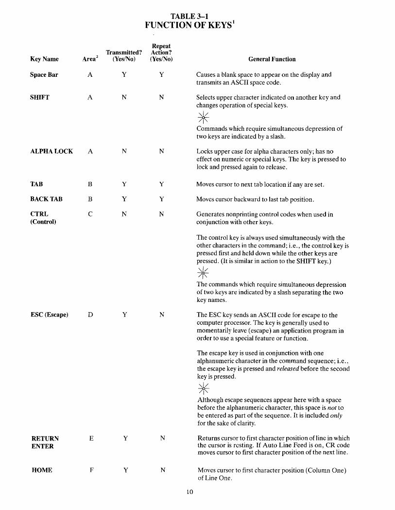
TABLE 3-1 FUNCTION OF KEYS·
Repeat Transmitted? Action?
Key Name Area2 (Yes/No) (Yes/No) General Function
Space Bar A Y Y Causes a blank space to appear on the display and transmits an ASCII space code.
SHIFT A N N Selects upper character indicated on another key and changes operation of special keys. ,,// -0-/1"
Commands which require simultaneous depression of two keys are indicated by a slash.
ALPHA LOCK A N N Locks upper case for alpha characters only; has no effect on numeric or special keys. The key is pressed to lock and pressed again to release.
TAB B Y Y Moves cursor to next tab location if any are set.
BACK TAB B Y Y Moves cursor backward to last tab position.
CTRL C N N Generates nonprinting control codes when used in (Control) conjunction with other keys.
The control key is always used simultaneously with the other characters in the command; i.e., the control key is pressed first and held down while the other keys are pressed. (It is similar in action to the SHIFf key.) ,,// -0-/1"
The commands which require simultaneous depression of two keys are indicated by a slash separating the two key names.
ESC (Escape) D Y N The ESC key sends an ASCII code for escape to the computer processor. The key is generally used to momentarily leave (escape) an application program in order to use a special feature or function.
The escape key is used in conjunction with one alphanumeric character in the command sequence; i.e., the escape key is pressed and released before the second key is pressed. ,,// -0-/1"
Although escape sequences appear here with a space before the alphanumeric character, this space is not to be entered as part of the sequence. It is included only for the sake of clarity.
RETURN E Y N Returns cursor to first character position of line in which ENTER the cursor is resting. If Auto Line Feed is on, CR code
moves cursor to first character position of the next line.
HOME F Y N Moves cursor to first character position (Column One) of Line One.
10

TABLE 3-1 Continued FUNCTION OF KEYS·
Repeat Transmitted? Action?
Key Name Area2 (Yes/No) (Yes/No)
LINEFEED, ~ F Y y
i F y y
BACKSPACE; ~ F Y y
---?> F y y
DEL (Delete) G Y y
BREAK H Y N
CLEAR SPACE I Y y
PRINT ] N N
NOTES 1. For Model 910 only. For emulations, see Table A-I. 2. Refer to Figure 3-1 for key location on keyboard.
3.3.2 Other Controls
Cursor-The lighted rectangular block (or underline) that appears on the screen indicates the entry spot for the following character to be typed. It is called a "cursor." During typing, the cursor moves from left to right. As it reaches the end of a line, it "wraps around" to the beginning of the next line, if auto wraparound mode is on. Otherwise, the cursor stays at the end of the line. If you place the cursor over a character which you have already typed, the character within the cursor will be changed into a reverse image within the cursor. (If the characters have been green on a black background, the cursor will appear as a green rectangle around a black character. ) The movement of the cursor is easy to control. To move the cursor, press one of the cursor control keys marked with an arrow. The cursor will move in the direction of the arrow until you release the key. To return the cursor quickly to the top left position on the screen, press HOME. The cursor will now be in Column One, Line One.
11
General Function
Moves cursor down one line.
Moves cursor up one line.
Moves cursor one character to the left.
Moves cursor one character to the right.
The DEL key sends an ASCII DEL character to the computer processor, and (depending on the terminal's communication mode) the computer program echoes the code back to the terminal to be performed. This is usually interpreted by the computer as a character erase code.
Transmits a 250-millisecond ASCII Break pulse to the computer.
Clears the screen to spaces and HOMES the cursor.
Toggles printer port on/off.
,,1/ -0-/1" If you are emulating the AD DS 25, pressing HOME will move the cursor to the lower lefthand corner of the screen .
...c i dll n J
Any desired cursor position in the display area can be programmed using an absolute cursor address of R (line or row) and C (column). (See 4.5 and Tables B-1 and C-l.)
Auto Scroll-When the terminal is turned on, the Auto Scroll feature will be activated. This feature causes the terminal to automatically scroll as the original display becomes full, making more screen available to you. On the last line, t or LINEFEED will cause the screen to scroll up.
With Auto Scroll off, the cursor will move downward as long as you press the t or LINEFEED keys. When the cursor reaches the last line, it will wrap back up to Line One (remaining in the same column position). To control the Auto Scroll feature, refer to 4.6.
Bell-The terminal can sound a short, loud bell upon your command. To sound the bell, press down CTRL and G at the same time.
'\1/ -0-/1'\
From now on, you will not be told to press CTRL and the other character at the same time. The command will be shown as CTRL/G instead.
Break-You can transmit a 250-millisecond break pulse (a break signal) to your computer system. The effect will depend on the operating program in your computer system. Usually it stops communication.
3.4 BASIC OPERATIONS
This section describes various options available to you as you use the terminal:
• Editing data
• Communicating with your computer system
• Printing
3.4.1 Tab Controls
You can set regular typewriter-style tabs on your terminal. Pressing the TAB key causes the cursor to stop whenever it reaches that column position, regardless of which line the cursor was on when the tab was set. Characters can be superimposed on the tab position. (At power ON, the terminal has tabs every eighth column position.)
Setting a Tab-To set a tab, move the cursor to the column position where you need a tab. Enter
ESC 1 (be sure you enter a numeral one, not a lower case "L")
Using the Tab Setting-When you want the cursor to go to the tab position, just press the TAB key. The cursor will move to the next tab setting in that line. When it reaches the last tab setting in that line, it will rest. To move the cursor to the previous tab setting, press BACK TAB.
Clearing Tabs-You can clear a specific tab by putting the cursor on the tab position you wish to clear and entering
ESC2
To clear all tabs, enter
ESC 3 (cursor position is not important)
3.4.2 Editing
Should you need to change text on the screen, you can erase a line (either partially or completely) or the whole display (either partially or completely). This will give you space to enter the correct data. Erasures will start with the column position under the cursor. The commands for editing are found in Table A-I.
12
3.4.3 Sending Data to the Computer
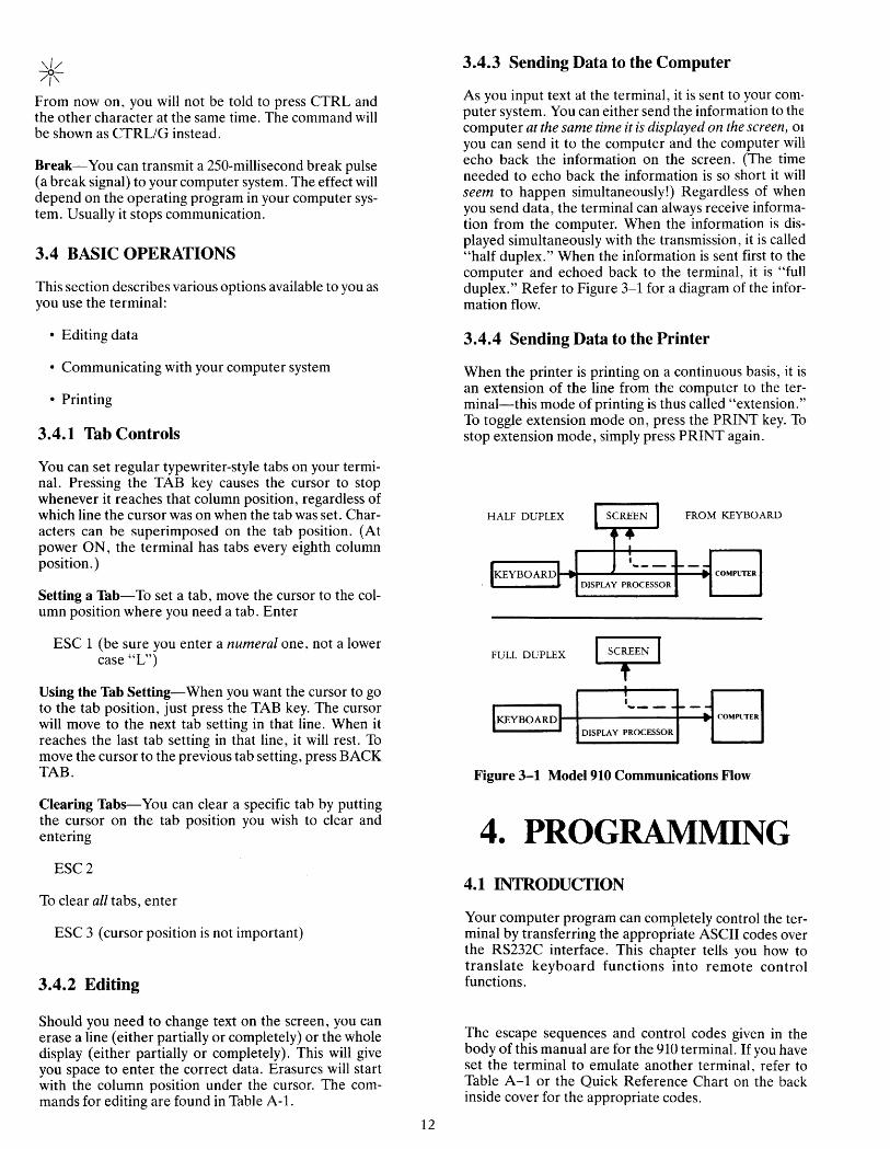
As you input text at the terminal, it is sent to your computer system. You can either send the information to the computer at the same time it is displayed on the screen, OJ
you can send it to the computer and the computer will echo back the information on the screen. (The time needed to echo back the information is so short it will seem to happen simultaneously!) Regardless of when you send data, the terminal can always receive information from the computer. When the information is displayed simultaneously with the transmission, it is called "half duplex." When the information is sent first to the computer and echoed back to the terminal, it is "full duplex." Refer to Figure 3-1 for a diagram of the information flow.
3.4.4 Sending Data to the Printer
When the printer is printing on a continuous basis, it is an extension of the line from the computer to the terminal-this mode of printing is thus called "extension." To toggle extension mode on, press the PRINT key. To stop extension mode, simply press PRINT again.
HALF DUPLEX FROM KEYBOARD
I-I ....... _...J... ___ ~_ .. COMPUTER
DISPLAY PROCESSOR
FULL DUPLEX
. : ---
IKEYBOARD:
... _-- ... COMPl'TER ... D1SPLA Y PROCESSOR
Figure 3-1 Model 910 Communications Flow
4. PROGRAMMING 4.1 INTRODUCTION
Your computer program can completely control the terminal by transferring the appropriate ASCII codes over the RS232C interface. This chapter tells you how to translate keyboard functions into remote control functions.
The escape sequences and control codes given in the body of this manual are for the 910 terminal. If you have set the terminal to emulate another terminal, refer to Table A-I or the Quick Reference Chart on the back inside cover for the appropriate codes.

4.2 MONITORING CONTROL COr~IMANDS
You can monitor control commands in several ways:
• Activate the monitor mode command without transmitting them to the computer
• Transmit control codes to the computer and display them
• Display only a single control character
Using monitor mode win make program debugging easier.
To activate display of control commands without transmitting a code to the computer, enter
CTRL/1
To terminate this mode, enter
CTRL/2
To enable monitor mode via the computer, enter
ESCU
Unless you are using half duplex, this must be echoed by the computer or monitor mode will not be activated.
To terminate the display of the control commands enter either '
ESCu or ESCX
To display a single control character, enter
ESCFn
where n is the control code to be displayed.
4.3 CONTROL FUNCTIONS
Wh~n the C~NTROL key is used with an alpha or numenc key, bIt 7 of the character which is typed is complemented (changed to the opposite), thus changing the ~ode transmitted by that character. Example: If "M" alone IS pressed, the code for M is sent. If "CTRL/M" are pressed, the code for a carriage return is sent.
4.4 FUNCT KEY
Using the FUNCT (function) key in combination with a~y one of the numeric keys enables you to quickly transmIt a three- or four-character sequence of commands. Table 4-1 indicates the code which is transmitted by each of the numeric keys when used with the FUNCT key.
13
To enter a function command, press the FUNCT key and at the same time press a numeric key. The first code which is transmitted will always be
SOH (Control A)
The second will be determined by the numeric key depressed (see Table 4-1). The third code will always be a CR. (Table 2-3).
Program the input/output string routine to catch the en!ire string and then process it (unless you are using an mterrupt-driven computer, in which case you do not need to worry about data being lost).
To eliminate the need for long or hard-to-remember sequen~es, you can. use the FUNCT key to trigger long functIOns or a cham of commands in the computer.
For ADM emulation, the FUNCT key sends STX plus numeric plus CR.
TABLE 4-1 FUNCTION KEY COMMANDS
Command ASCII Code Transmitted
FUNCT/O SOH@ + CR
FUNCT/1 SOHA + CR
FUNCT12 SOHB + CR
FUNCT/3 SOHC + CR
FUNCT/4 SOHD + CR
FUNCT/5 SOHE + CR
FUNCT/6 SOHF + CR
FUNCTI7 SOHG + CR
FUNCT/8 SOHH + CR
FUNCT/9 SOHI + CR
4.5 ADDRESSING THE CURSOR
The computer can tell the terminal where to position the cursor with a four-character escape sequence. (See Table 4-1.) This is called "loading" the cursor.
To load the cursor, enter
ESC = RC
The Rand C represent the absolute row or line (R) and column (C) where the cursor will rest. Using Table B-1, find the ASCII code representing the desired row. (If you are emulating ADDS, use Table C-l.) Note that the row number can not be greater than 24. Enter the appropriate ASCII code. Next find the ASCII code corresponding to the desired column position (1 through 80 possible) and enter that code. For example, if you want to program the cursor to go to Row 9, Column 50, enter
ESC = (0

If your computer system inserts nulls between characters, loading the cursor will not function as describedinstead the cursor will go to an unpredictable position.
To load only the column, enter
ESC]C
and to load only the row, enter
ESC[R
where Rand C are the row and column values.
The computer can also "read" the cursor's row and column position. To read the cursor's position, enter
ESC?
Following the cursor coordinates (row and column), the terminal will transmit a carriage return code.
4.6 AUTO SCROLL
You can program the terminal to automatically scroll to a new line as the original display becomes full. The escape sequence which controls this Auto Scroll feature toggles the feature on and off. To start or stop Auto Scroll, enter
ESCH
When the terminal is powered on, Auto Scroll is on.
(Refer also to 3.3.2 for a description of cursor movement when Auto Scroll is not used.)
4.7 VISUAL ATTRIBUTES
You can define the appearance of each line on the screen (a whole line or only part of aline). Each line must be defined separately (except half intensity). The choices available are:
Reverse Video Changes background of screen on that line to the reverse of that which appears on power ON. If screen is normally black with green characters, this line will now be green with black characters.
Half Intensity Changes intensity of the line to half of normal.
,,1/ -0-/1" Half intensity differs from other visual attributes in that once it is set, it affects all characters entered, regardless of cursor position, until it is turned off.
Underline Fills that line with underlines.
Blink Causes all characters on the line to blink.
14
Blank All data entered on the line will be invisible to you but will print out and be transmitted to the computer.
Setting-To set a visual attribute, place the cursor one position before you want the attribute to start. Attribute occupy a character position. If you want the whole line changed, place the cursor at Column One before entering the attribute command (ESC Gn).
TABLE 4-2 ESCAPE SEQUENCES FOR
VISUAL ATTRIBUTES
Description Normal video Blank (invisible normal video) Blink Blank (invisible blink) Reverse video Blank (invisible reverse video) Reverse and blink Blank (invisible reverse blink) Underline Blank (invisible underline) Underline and blink Blank (invisible blink underline) Underline and reverse Blank (invisible underline reverse) Underline and reverse and blink Blank (invisible underline reverse blink)
4.8 ENABLING/DISABLING THE PRINTER
Escape Sequence ESC GO ESCGl ESCG2 ESCG3 ESCG4 ESCG5 ESCG6 ESCG7 ESCG8 ESCG9 ESCG: ESCG; ESCG< ESCG= ESCG> ESCG?
To turn on the printer port and also simultaneously display data on the screen, either press PRINT or enter
ESC@'
This turns extension and update modes on. Should you only want to activate the printer port and NOT update the display screen, enter
CTRL/R
This turns on transparent and extension modes.
To toggle the printer off (together with the transparent mode), press PRINT again or enter
ESCA
If you had the printer on without screen update (transparent) and want to update and print, enter
CTRL/T or ESC @
Thus using the PRINT key simply toggles the printer port on and off.
When the terminal is turned on, the default condition is printer port off and display update on.

MONITOR MODE CODES
CHARACTER SETS
HALF INTENSITY
BLANK REVERSE
REVERSE
BLINK REVERSE
NORMAL VIDEO
BLANKNORMAL BLINK NORMAL
BLANK BLINK
REVERSE UNDERLINE
BLANK REVERSE UNDERLINE
BLINK REVERSE UNDERLINE
BLANK BLINK REVERSE
NORMAL UNDERLINE BLANK NORMAL UNDERLINE BLINK NORMAL UNDERLINE
S1, S2 (displayed in reverse order, i.e. 10-1)
X's DON'T CHANGE
Figure 4-1 Model 910 Video Attributes and Monitor Mode
4.8.1 DTR (Data Terminal Ready) Control and To subsequently enable it, you must receive an ESC" or X-ON/X-OFF type a SHIFf/BREAK BREAK (reset) from the key
board. DTR control (a voltage change on pin 20 of the RS232 connectors) and X-On/X-Off (ASCII characters) are prearranged signals that control data flow between the printer, terminal, and computer (or modem).
You determine which signals are sent with switch settings and commands. S2 DIP switch 10 determines whether DTR control is enabled. Setting this switch in the "down" position enables DTR control by physically connecting the DTR line. X-On/X-Off is enabled at power on. To disable X-On/X-Off, enter CTRL/N from the keyboard or computer. To reenable X-On/X-Off, enter CTRL/O.
If the terminal sends data faster than the printer can print it, the printer lowers DTR, triggering the terminal to send X-Off (or lower DTR) to the computer. In response, the computer should stop sending data. Once the printer can accept more data, it raises DTR. The terminal sends X-On (or raises DTR) to the computer, telling it to resume sending data.
4.9 DISABLING THE KEYBOARD
You can disable all keyboard functions by remote commands from the computer. Once the keyboard is disabled, it can only be enabled once again by another remote command from the computer.
S If your computer system echoes all codes, the keyboard may be accidentally disabled.
To disable the keyboard remotely, enter
ESC #
While the keyboard is disabled, all keys are disabled except FUNCT, PRINT, BREAK, CTRL/1, and CTRL/2.
15
4.10 WORD STRUCTURE, PARITY SETTINGS, AND STOP BITS
Each computer system has its own method for checking the transmission of characters from the terminal to verify receipt. In Chapter 2 you were shown how to set the switches in the terminal to match the requirements of your computer system. This section explains the meaning and importance of those settings.
The terminal communicates with the computer in a code called "American Standard Code for Information Interchange," usually abbreviated to ASCII (pronounced ask-key). The code consists of 128 characters in a 7-bit binary format (each bit is either a one or a zero).
The first bit of the transmission is always used as a start bit to tell the computer that a character will be transmitted. (This is not part of the character code.) This start bit is always a zero. A one may also be referred to as false or mark or low. A zero bit can also be called a true, space, or high. (These signal levels and names are RS232 EIA standards. )
Following the start bit, the terminal will now send either a 7- or 8-bit character code. These are data bits.
To verify correct receipt of the character code, computers may now require that the next bit received serve as a check on the transmission. This is called parity. Several methods are used, varying from system to system. The methods used are listed in Table 4-3.
Following any parity bit required, the terminal will also send (as set by the switch settings) either one or two stop bits to signal the end of the character code transmission. Stop bits are always ones.

Figure 4-2 shows the structure of a serial data word.
Start Data, parity, stop bit
Data bit Stop or not used
I I I
Parity, stop bit, not used
Figure 4-2 Bit Structure of a Serial Data Word
TABLE 4-3 SWITCH SETTINGS FOR PARITY
AND DATA BITS
SI Switch Setting Parity Position Up Down Description
Requires that the total number of true data bits received be odd or
7 ODD even. Terminal will
x add a one or zero as x EVEN necessary to make the total number of data bits sent either odd or even.
8 Xl MARK or Requires that a one FALSE be sent in the parity
position.
5 x2 SPACE or Requires that a space TRUE be sent in the parity
position.
6 x SEND Allows an odd or even parity bit to be sent.
x NONE Does not require a (or NO) parity bit to be sent.
5 x Causes 7 data bits to be sent.
NOTES
1. Selecting 2 stop bits on the Model 910 results in MARK parity. 2. Selecting 8 data bits on the Model 910 results in SPACE parity.
4.11 CUSTOM RAM AND ROM APPLICATIONS
You can replace the 2532 ROM (supplied with the 910 terminal) with a 2564 ROM. This replacement will provide an additional 4K ROM, giving you a total of 8K ROM space for special application programs.
16
4.12 CURSOR APPEARANCE
You can change the appearance of the cursor with the following commands:
Cursor off Blinking block cursor Steady block cursor Blinking underline Steady underline
4.13 BELL
ESC.O ESC.1 ESC.2 ESC.3 ESC.4
You can cause a short loud bell to sound by entering
CTRL/G
5. PREVENTIVE MAINTENANCE
5.1 CARE
Tender loving care will prolong the useful life of your terminal. Clean and inspect it periodically.
5.1.1 Cleaning
To clean the terminal exterior:
1. Vacuum the keyboard every three months with a soft brush attachment (or use a small soft brush).
2. Clean the housing with a soft, lint-free cloth and a commercial detergent every three months.
8 DO NOT use solvent-based or abrasive cleaners.
5.1.2 Inspection
Check the cabinet and keyboard for damage or excessive wear.
Description
1. Inspect the terminal cabinet for cracks or breaks.
2. Check each key for free movement.
3. Check the cable connector (at the rear of the terminal cabinet) for damage.
Frequency
lIYr.
lIYr.
l/Yr.

6. TROLTBLESHOOTING AND REPAIR
6.1 TROUBLESHOOTING
Your ~omputer terminal is just one of several components m the computer system. A failure anywhere else in the system can cause the improper operation of the terminal. The computer system, memory systems, cabies, modems, and operational procedures should be checked ~f there ha.s ?een a malfunction. Table 6-1 will be helpful m determmmg the cause of a problem. If this table does not help locate the cause of a problem, run the self test or call a qualified service technician for assistance.
6.1.1 Testing the Terminal (Self Test)
You. can test the terminal yourself to verify proper operatIOn of the video display circuitry, the transmit and receive portion of the RS232C interface, and the control processor. The test will display all displayable characters and all 16 video attributes.
To start the test you must be in 910 mode and half duplex. Enter
ESCV
The display screen should now look like that in Figure 4-1. Look at the display carefully to verify that all characters appear, all video attributes appear correctly and all half intensity characters are shown. Each char~cter should be formed properly and you should not be able to see any extra dots (and no dots should be missing).
Check the switch settings on the terminal against those on the display (see Fig. 4-1). The display will show the dip switches as a 1 (up) or a 0 (down).
To stop the test so you can type, type 0 (alpha, not zero) or press SHIFTIBREAK BREAK.
Should your display not appear as pictured in Figure 4-1 call a qualified service technician.
,,1/ /I~ Switch S1-9 must be UP or the self test will fail.
6.2 REPAIR
Model 910 operator repair is limited to changing the line fuse and the two internal power supply fuses.
17
6.2.1 Changing the Line Fuse
To change the line fuse, proceed as follows:
8 To avoid electrical shock, disconnect the terminal power cord before changing the line fuse.
1. Disconnect the terminal power cord from primary power.
2. Remove the fuse holder (see Figure 2-2) by unscrewing it counterclockwise.
3. Remove the blown fuse. For 110 volt applications, install a 3AG, 1 amp 125 volt fast blow fuse. For 220 volt AC applications, install a 0.5 amp 220 volt slow blow fuse.
4. Install the fuse in the reverse order of Steps 1 through 3.
6.2.2 Changing the Power Supply Fuses
The terminal power supply fuses are installed in fuse clips on the power supply assembly inside the terminal. To replace either of these fuses, proceed as follows:
8 Hazardous voltages are exposed in the cabinet. Turn off the power switch and disconnect power before opening the terminal cabinet.
1. Disconnect the terminal power cord from primary power.
2. Turn the terminal upside down and set it on a soft surface to prevent marring the cabinet. Remove the two Phillips screws that hold the cabinet cover on the terminal.
3. Turn the terminal right side up and lift off the cabinet cover. ,,\/ -0-/1" Make sure there is adequate table space for the open terminal. It is top heavy and could fall over.
4. Remove the blown fuse from its fuse clip (see Figure 2-4).
5. Replace the blown fuse with a 3AG, 3 amp, 125V fuse.
6. Reinstall the terminal cover and secure it with the two screws. (Do not overtighten screws!)

TABLE 6-1 TROUBLESHOOTING TERMINAL PROBLEMS
Symptom
Terminal dead (no beep; no cursor)
Terminal dead; cursor may appear
Terminal will not go on line
Cursor will not appear
System does not respond while on line
Terminal is not responding to settings
Terminal "locked up"
Terminal locked up
Possible Cause
No ACpower
Loose or defective line or power supply fuses
System is not "up"
Loose, unconnected, or damaged cables
Modem not turned on, defective, or phone handset on modem upside down
Defective contrast pot Contrast set too light
Incorrect parity switch setting, word structure, stop bits
Terminal not powered down after being reconfigured; software has not scanned new settings.
System is not responding; communication link broken
Terminal incorrectly set for on line and full duplex
Keyboard disabled from computer
Switches set incorrectly
18
Solution
Plug in power cord. Turn on power switch. Check 115/230 power switch setting. Check for loose connections.
Turn terminal power off and change fuses.
Check status of system.
Attach all cables and check for cable damage.
Check main port (P3) interface cable pins:
• 5,6, and 8 must be driven by + 12 VDC or not connected at all for normal operation.
• 1 and 7 must be grounded. • 3 must be connected to the host
transmitter. • 2 must be connected to the host
receIver.
Turn on modem. Attach different modem. Check phone handset position.
Refer to technical representative for adjustment of contrast settings.
Set parity switch to match system.
Power down terminal and turn back on.
Set to half duplex and try to type. If terminal will type, check cables, modem, phone lines, and computer system. Set to full duplex and perform self test.
Set to half duplex.
Enter ESC # or press SHIFTI BREAK BREAK.
Review Chapter 2 switch settings carefully and check all switch settings.

TABLE 6-1 Continued TROUBLESHOOTING TERMINAL PROBLEMS
Symptom
Terminal prints correct data only part of the time
Display is wavy
Printer does not print what is typed
Escape and control codes do not function as specified
Terminal prints "garbage" or@symbols
Possible Cause
Parity settings incorrect
Stop bits or word structure wrong
Hertz setting incorrect; does not match local power frequency
Correct print mode selected?
Cable connector pins connected incorrectly
The escape and/or control codes being used are not correct
Keyboard locked in SHIff position (AUTO LOCK on)
Improper baud rate setting Improper stop bit setting Improper word length setting Improper parity setting
Defective modem
Noisy telephone lines
Static electricity
19
Solution
Check parity settings with system requirements.
Change switch settings.
Change switch setting.
Refer to 3.4 and 4.8.
Refer to 2.4
Check printer port (P4) interface cable connector pins:
• 4 or 20 must be driven by + 12 VDC or not connected at all for normal operation
• 3 must be connected to printer data input
Check other printer port device requirements.
Check model number of terminal and code table for correct model of terminal being used.
Make sure upper and lower case codes are used. Is a numeral one required instead of lowercase "L"?
Put in lower case. Connect P3-2 to P3-3 and try in full duplex. Disconnect computer system.
Set correct switch settings
Replace modem.
Check phone lines. Install dedicated phone lines.
Check operating environment for static.
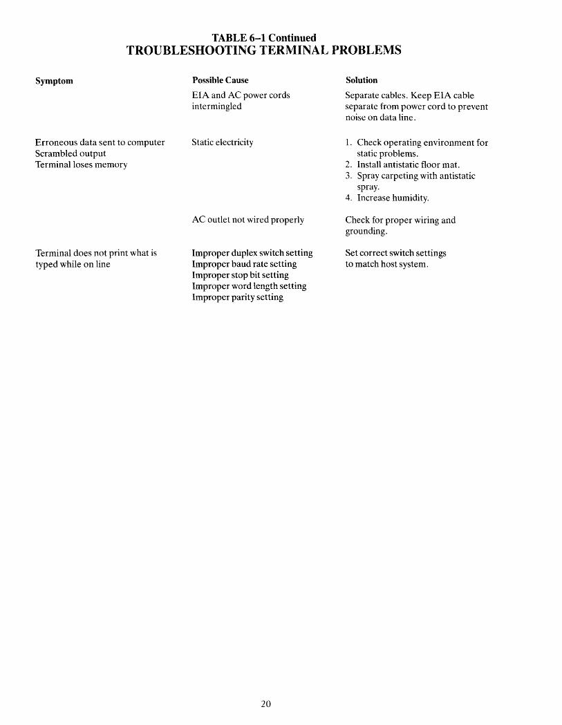
TABLE 6-1 Continued TROUBLESHOOTING TERMINAL PROBLEMS
Symptom
Erroneous data sent to computer Scrambled output Terminal loses memory
Terminal does not print what is typed while on line
Possible Cause
EIA and AC power cords intermingled
Static electricity
AC outlet not wired properly
Improper duplex switch setting Improper baud rate setting Improper stop bit setting Improper word length setting Improper parity setting
20
Solution
Separate cables. Keep EIA cable separate from power cord to prevent noise on data line.
1. Check operating environment for static problems.
2. Install antistatic floor mat. 3. Spray carpeting with antistatic
spray. 4. Increase humidity.
Check for proper wiring and grounding.
Set correct switch settings to match host system.

i I
TABLE A-I I
I SUMMARY OF FUNCTIONAL COMMANDS
Command l•2 I Function Key 910 LS Hzltn ADDS Description
MOVE CURSOR
Home HOME CRTLI /\ CTRLI /\ ESCCTRLlR CTRLlA Moves cursor to Column One of Line One.
Newline CTRLI_ *CTRLI_ *CTRLI_ Moves cursor to Column One of next line.
Carriage return RETURN CTRLlM CTRLlM CTRLlM CTRLlM Returns cursor to Column One of
ENTER line in which the cursor is resting.
Cursor down t . LINEFEED CTRLlJ CTRLlJ CTRLJ CTRLlJ Moves cursor down one line.
Cursor up i CTRLlK CTRLlK *ESCCTRLlL CTRLlZ Moves cursor up one line.
Cursor left ~ ,BACKSPACE CTRLlH CTRLlH CTRLlH CTRLlH Moves cursor one character position CTRLlU to the left.
Cursor right ~ CTRLlL CTRLlL CTRLlP CTRLlF Moves cursor one character position
to the right. CURSOR APPEARANCE
Cursor off ESC.O Makes cursor disappear
Blinking block cursor ESC.1 Makes cursor appear as blinking square
Steady block cursor ESC.2 Makes cursor appear as steady square
Blinking underline ESC.3 Makes cursor appear as blinking underline
Steady underline ESC.4 Makes cursor appear as steady underline
TAB CONTROL
Set column tab ESC 1 *ESC 1 *ESC 1 *ESC 1 Sets typewriter-type tab for entire column (from top to bottom of screen) at cursor location.
Clear tab ESC2 *ESC2 *ESC2 *ESC2 Clears tab at cursor location.
Clear all tabs ESC3 *ESC3 *ESC3 Clears all tabs on screen.
Back tab BACK TAB ESCI *ESC I *ESCI *ESCI Moves cursor back to previous tab position. If no previous tabs set, moves cursor to Column One of that line.
Move to tab TAB CTRLlI CTRLlI *CTRLlI CTRLlI Cursor moves to nexttab location (if CTRLlN any). If there are no more tabs set,
cursor does not move.
EDIT
Erase line; ESCT ESCT *ESCCTRLlO ESCK Erases characters from cursor to change to spaces end of line and replaces them with
spaces.
Erase page; ESCY ESCY *ESCCTRLlX ESCk Erases characters from cursor to change to spaces end of page and replaces them with
spaces.
Clear screen; CLEAR ESC + CTRLlZ ESCCTRL \ CTRLlL Clears entire screen and changes it change to spaces CTRLlZ to spaces. If half-intensity was on,
replaces the page with half-intensity spaces.
Clear screen; SHIFT/CLEAR ESC * *ESC * ESC * Clears entire screen and changes it change to nulls to nulls. Cursor position is not
important. Sends cursor to HOME position.
21

TABLE A-I Continued SUMMARY OF FUNCTIONAL COMMANDS
Commandl•2
Function Key 910 LS Hzltn ADDS Description
CURSOR ADDRESS
Load cursor (line or row) ESC[R *ESC[R CTRLlKR Allows host to control cursor position within the row where R is absolute row. See Table B-1 for value of R (Table C-l for ADDS emulation).
Load cursor (column) ESC]C *ESC)C CTRLlPC Allows host to control cursor position within column upon transmission of sequence where C is column. See Table B-1 (C-1 for ADDS emulation) for coordinate value.
Load cursor ESC =RC ESC =RC ESCYRC Allows host to position cursor at (row, column) row and column. See Table B-1 for
coordinate values. (Table C-1 for ADDS emulation.)
Load cursor ESCCTRLI Allows host to position cursor at (column, row) QCR row and column. See Table B-1 for
coordinate values.
Read cursor ESC? *ESC? *ESC? Transmits row and column (row, column) coordinates of cursor, followed by
the terminator character, to the computer. (See Tables B-1, C-1.)
Read cursor ESC CTRL E Transmits row and column position (column, row) of cursor plus terminator character
to the computer.
KEYBOARD
Enable keyboard ESC" **ESC" ESCCTRLlF ESC6 Enables keyboard to be used. Can only be caused by input from the computer.
Disable keyboard ESC# **ESC# ESCCTRLlU ESC5 Disables keyboard.
PRINTER
Enable printer port ESC@ CTRLIN *ESC/ CTRLlR Enables printer to start printing; screen will display updated data.
Disable printer port ESCA CTRLlO *ESC? CTRLIT Disables printer port; leaves display update on.
Enable transparent CTRLlR *ESC@ *ESC* ESC3 Enables transparent print mode; print screen will not display updated data.
Disable transparent CTRLIT *ESCA *ESC/ ESC4 Disables transparent print mode; print screen will display updated data.
VISUAL ATTRIBUTES
Normal video ESC GO *ESC CTRLlGO ESC GO (same as set during installation)
Invisible normal ESCGl *ESC CTRLlG 1 ESCGl Characters transmitted but invisible (blank) on screen.
22

TABLE A-I Continued SUMMARY OF FUNCTIONAL COMMANDS
Commandl,2
Function Key 910 LS Hzltn ADDS Description
Blink ESCG2 *ESC CTRLlG2 ESCG2 Characters blink on/off beginning at cursor position.
Invisible blink ESCG3 *ESC CTRLlG3 *ESCG3 Characters transmitted but (blank) invisible on screen.
Reverse (opposite ESCG4 *ESC CTRLlG4 *ESCG4 Black/green display (opposite of of that set during installation selection) beginning at installation) cursor when set.
Invisible reverse ESCG5 *ESC CTRLlG5 *ESCG5 Characters transmitted but (blank) invisible on screen.
Reverse blink ESCG6 *ESC CTRLlG6 *ESCG6 Reverse video, blinking beginning where cursor was set.
Invisible blink ESCG7 *ESC CTRLlG7 *ESC G7 Characters transmitted but reverse (blank) invisible on screen.
Underline ESCG8 *ESC CTRLlG8 *ESCG8 Line is underlined, beginning where cursor is when set.
Invisible underline ESCG9 *ESC CTRLlG9 *ESCG9 Characters transmitted but (blank) invisible on screen.
Blink underline ESCG: *ESC CTRLlG: *ESCG: Blinking underline beginning where cursor is when set
Invisible blink ESCG; *ESC CTRLlG; *ESC G; Characters transmitted but underline (blank) invisible on screen.
Reverse underline ESCG< *ESC CTRLlG < *ESCG < Line reverse video and underlined, beginning where cursor is when set.
Invisible reverse ESCG = *ESC CTRLlG = *ESCG = Characters transmitted but underline (blank) invisible on screen.
Reverse blink ESCG> *ESC CTRLlG > *ESCG> Line reversed, underlined, and underline blinking beginning where cursor is
when set.
Invisible reverse blink ESCG? *ESC CTRLlG ? *ESCG? Characters transmitted but underline (blank) invisible on screen.
Half intensity on ESC) ESC) *ESCCTRLN *ESCG) Changes screen to half intensity.
Half intensity off ESC( ESC( *ESCCTRLI_ *ESC G ( Turns off half intensity.
Display normal/reverse ESCG Toggles normal display off and on (ADM-3A/5 only)
Cursor visible/invisible *ESC. *ESC. Toggles cursor on/off.
MONITOR
Display control ESCFn *ESCFn ESCZn Displays selected control character character where "n" is character to be
displayed.
Monitor off (local) CTRLl2 *CTRLl2 *CTRLl2 *CTRLl2 Stops monitor mode.
Monitor on ESCU *ESCU Transmits control codes to computer and displays them.
Monitor off ESCu *ESCu Stops monitor mode. ESCX ESCX
23

TABLE A-I Continued SUMMARY OF FUNCTIONAL COMMANDS
Function
MONITOR
Monitor on (local)
MISCELLANEOUS
Self test on
Auto scroll on/off
Bell
Legend
Key 910
CfRLlI
ESC V
ESCH
CfRLlG
Commandl ,2
LS Hzltn
*CTRLll *CTRLll
*ESCV ESC CfRLlS
*ESCH
CTRLlG *CTRLlG
ADDS Description
*CTRLlI Displays control codes without transmitting them.
*ESCV
*ESCH
CTRLlG
Starts self test
Toggles Auto Scroll on/off. Auto Scroll permits another line when screen is full.
910 = TeleVideo 910; LS = Lear Siegler ADM-5/3A; Hzltn = Hazeltine 1410; ADDS = ADDS 25
NOTE
1. Slash means depress CTRL key at same time control character is pressed. ESC CTRLI means press and release ESC key before pressing CfRL and other character. Do not add spaces. User upper and lower case characters as indicated.
2. For transmitted code sequences for each function, refer to the Command column.
* Additional emulation codes.
** Differs from original code.
TABLE B-1 CURSOR COORDINATES
CURSOR POSITIONING
POSITION ASCII CODE POSITION ASCII CODE POSITION ASCII CODE RorC* Transmitted C Transmitted C Transmitted
1 Space 33 @' 65 2 ! 34 A 66 a 3 35 B 67 b 4 # 36 C 68 c 5 $ 37 D 69 d 6 % 38 E 70 e 7 & 39 F 71 f 8 40 G 72 g 9 41 H 73 h
10 42 I 74 11 43 J 75 j 12 + 44 K 76 k 13 45 L 77 I 14 46 M 78 m 15 47 N 79 n 16 / 48 0 80 0
17 0 49 P 18 1 50 Q 19 2 51 R 20 3 52 S 21 4 53 T 22 5 54 U 23 6 55 V 24 7 56 W 25 8 57 X 26 9 58 Y 27 59 Z 28 60 [ 29 < 61 \ 30 62 ] 31 > 63 /\ 32 64
* Value of R can't be greater than 24. 24

TABLEC-l ADDS CURSOR COORDINATES
Row ASCII Code Column ASCII Code Column ASCII Code Position Transmitted Position Transmitted Position T .. ansmitted
1 ca 1 CTRLI(cl 41 ca 2 A 2 CTRLlA 42 A 3 B 3 CTRLlB 43 B 4 C 4 CTRLlC 44 C 5 D 5 CTRLlD 45 D 6 E 6 CTRLlE 46 E 7 F 7 CTRLlF 47 F 8 G 8 CTRLlG 48 G 9 H 9 CTRLlH 49 H
10 I 10 CTRLlI 50 I 11 J 11 CTRLlP 51 P 12 K 12 CTRLlQ 52 Q 13 L 13 CTRLlR 53 R 14 M 14 CTRLlS 54 S 15 N 15 CTRLlT 55 T 16 0 16 CTRLlU 56 U 17 P 17 CTRLlV 57 V 18 Q 18 CTRLlW 58 W 19 R 19 CTRLlX 59 X 20 S 20 CTRLlY 60 Y 21 T 21 SP 61 / 22 U 22 62 a 23 V 23 63 b 24 W 24 # 64 c
25 $ 65 d 26 o/c 66 e 27 & 67 f 28 68 g 29 ( 69 h 30 ) 70 31 0 71 P 32 72 q 33 2 73 34 3 74 35 4 75 36 5 76 u 37 6 77 \"
38 7 78 w 39 8 79 x 40 9 80 Y
TABLED-l ASCII Chart
~ . 00 00 0 1 0 1 1 0 1 0 11 1 1 B _ 6 bs ~ ~ 0 1 0 1 0 1 0 1
Its ~4 ~3,~2 bt'~ 0 1 2 3 4 5 6 7 o 0 o 0 0 NUL OLE SP 0 @ P ... P
o 0 o 1 1 SOH DCl ! 1 A Q a q
o 0 1 0 2 STX DC2 " 2 B R b r
o 0 1 1 3 ETX DC3 * 3 C S c s o 1 o 0 4 EOT DC4 S 4 0 T d t o 1 o 1 5 ENQ NAK % 5 E U e u o 1 1 0 6 ACK SYNt & 6 F V f y
o 1 1 1 1 BEL ETB , 1 G W 9 w 1 000 8 BS-- CAN ( 8 H X h x 1 001 9 SKIP EM ) 9 I Y i y HT
1 010 10 IF SUB * : J Z j z 1 o 1 1 11 VT+ ESC + ; K [ k { 1 1 o 0 12 FF-- FS < l \ I I ,
I
1 1 o 1 13 CR GS - = M 1 m } 1 1 1 0 14 SO HOME > N 1\ n --RS
1 1 1 1 15 SI NEW LINE / ? 0 DEL US - 0 RUB
25

Addressing cursor, 4.5 ASCII codes, 4.10, TC-1 Attributes, visual, 4.7, TA-1 Auto Scroll, 3.3.2, 4.6, TA-1
Baud rate settings, 2.4, T2-3, T6-1, 3.2.1 Bell, 3.3.2, TA-1 Blank, 4.7, TA-1 Blink, 4.7, TA-1 Break, 3.3.2, TA-1
Character sets, vi, 2.4.4, T2-6 Clear, T3-1, TA-1 Computer connection, T4.2, T2-2 Contrast, screen, 3.2.2, T6-1 Control commands, 4.2, 4.3, TA-1 Control key functions, T3-1, TA-1 Cursor, addressing, 4.5
appearance, T2-3, 3.3.2 controls, 3.32, TA-1 loading, 4.5, TB-1 reading, TB-1
Customizing RAM/ROM, 4.11
Data bits, TI-3, T2-4, T4-3, 4.10 Data Carrier Detect, T2-3, T2-1 Data Set Ready, T2-3, T2-1 Data Terminal Ready, TI-3, TI-1, 4.8.1 Dimensions, iii, F2-1 Display, (see also screen)
update, 4.8 Duplex, full, T2-3, 3.4.3, T6-1
half, T2-3, 3.4.3, T6-1 setting, T2-3
Edit commands, 3.4.2, TA-1 Emulations, 2.4.4, TI-6, TA-1 Escape functions
key, T3-1 sequences, TA-1
Extension mode, 3.4.4, TA-1
FUNCTion key, T3-1, 4.4, T4-1 Fuses, changing, 6.2
Half intensity, 4.7, T4-2 Hertz settings, 2.4.4, T2-3
Inspection, 2.2, 5.1 Installation, 2.4
checklist, 2.5 Interface connections, 2.4.2, T2-1
Jumper options, T2-5, T2-6
INDEX
26
Key functions, T3-1, TA-1 repeat action, T3-1
Keyboard controls, 3.3, TA-1 enable/disable, 4.9, TA-1 layout, 3.3.1, F3-1, TB-1
Line frequency (see Hertz) Logic board, F2-3
Maintenance, CH 5 contract, iii
Manual, how to use, 1.2 Monitor mode, 4.2, TA-1
Operation, CH3, 3.2 Operator's Quick Reference Guide, inside back cover
Parity settings, 2.4.4, T2-3, T2-4, 4.10, T4-3, F4-2, T6-1
Physical requirements, iii, 2.3.2, F2-1 Pin connections, 2.4.2, T2-1, 2.4.3, T2-2 Power configuration, iii, 2.4.1, T2-3
requirements, 2.3.1 select switch, 2.4.1, F2-2
Printer enable/disable, 4.8, TA-1 interface, 2.4.3, T2-2
Programming, CH. 4 debugging, 4.2 notes, 1.2
RAM changes, 4.11 Rear panel, F2-2, 3.2.1 Repair, 6.2 Reporting damage, 2.2.4 Reset, 2.4.4, 4.9 Returned Material Authorization, ii Reverse video, 4.7, T4-2, TA-1 ROM changes, 4.11 RS232, T2-5
Safety precautions, 1.4 Screen update, 4.8, TA-1 Self-test, 6.1 Sending data to computer, 3.4.3, TA-1
data to printer, 3.4.4, 4.8, TA-1 Serial number, ii Service, ii Shipping, ii, 2.2.5 Signals, 2.4.4, T2-1 Site preparation, 2.3 Specifications, iii Start bit, 4.10 STOP notes, 1.2 Stop bits, 2.4.4, T2-3, T2-4, 4.10, F4-2, T4-3

Strapping (see Jumper Options) Switch settings, 2.4.4, T2-3, T2-4
record of, inside front cover Symbols, 1.2
Tab controls, T3-1, 3.4.1, TA-1 Technical assistance, ii Terminal, adjusting, 3.2.2
cleaning, 5.4 configuration, Ch 2 description, 1.3 interior, F2-4 protection, 1.5, CH. 5 turning on, 2.5, 3.2
Terminating character, 2.4.4, T2-3, 4.4, T4-1 Test, self, 6.1.1 Transmitting to computer, 3.4.3
to printer, 3.4.4 Troubleshooting, CH. 6, T6-1 Turn-on procedure, 3.2
Underlining, 4.7, T4-2, TA-1 Unpacking, 2.2.2 Updating screen (see Display)
Video display, 2.4.4, T2-3, 4.7,4.2 Visual attributes, 4.7, T4-2
Warranty, extended, ii limited, ii service under, ii service not under, ii
Word structure, 2.4.4, T2-3, T2-4, 4.10, F4-2
X-Onl X-Off, 4.8.1
GLOSSARY ASCII The acronym for American Standard Code for Information Interchange. This is a standardized code for the transmission of data within the United States. It is composed of 128 characters (upper and lowercase letters, numerals, punctuation marks, symbols, and control characters) in a 7-bit binary format.
Asynchronous Communication A method of communication where the time synchronization of the transmission of data between the sending and receiving stations is set by start and stop bits and the baud rate.
Baud The rate of transmission of data. One baud equals one binary bit per second.
27
Bit An abbreviation for binary digit. A bit is the smallest unit of data. ASCII codes are composed of seven bits.
BREAK To break or interrupt communications. When the BREAK switch on the terminal is toggled, a 2S0-millisecond tone is sent to the computer to immediately halt comm unications.
Buffer An electronic device within the terminal that allows for the temporary storage of incoming data should the transmission rate of the incoming data be faster than the terminal's printing speed.
Bug An error in a computer program or in the operation of the computer.
Byte A coded group of binary bits which represents a character (letter, numeral, symbol, command, etc.).
Code A method of representing data by groups of binary digits.
Command A code that will cause the terminal or computer to perform an electronic or mechanical action.
Computer An electronic system which, in accordance with its programming, will store and process information and perform high-speed mathematical or logical operations.
Control Codes Special nonprinting codes which cause the terminal or computer to perform specific electronic or mechanical actions (such as setting tabs, etc.).
CPU Central Processing Unit. The "brains" of a computer or computer terminal; that section where the logic and control functions are performed.
Default Condition which exists from POWER ON or RESET if no instructions to the contrary are given to the terminal.
DEL The ASCII DELETE code used in some instances to delete transmitted characters or to exit modes of operation.

Digit One of the numerals in a number system.
Digital Information in the form of individual parts-bits or digits.
EOT An ASCII code that means "end of transmission" (EaT); used in the EaT lACK handshaking protocol. The computer sends an EaT at the end of each transmission to the terminal. When the terminal is ready to receive more data, it transmits an acknowledge (ACK) back to the computer.
ESC An ASCII code meaning "escape" which is used to control various electronic and mechanical functions of the terminal.
Full Duplex In full duplex communication, the terminal can transmit and receive simultaneously. The transmitted data is not printed locally unless it is "echoed back" by the computer.
Half Duplex In half duplex communication, the terminal transmits and receives data in separate, consecutive operations. Transmitted data is printed locally.
Handshaking A communications protocol which is necessarily used when the transmitting speed of the computer is faster than the printing speed of the terminal. It consists of a set of commands, recognized by both stations, which control the flow of the data transmission from the computer.
Hardware The electronic components of a computer system or terminal.
Host The computer system.
Interface A communications channel which is typically used for external devices.
Main The computer system.
Memory That part of a computer system or terminal where information is stored.
28
Microprocessor An electronic circuit on the surface of a small silicon chip which can be programmed to perform a wide variety of functions within the computer system or terminal.
Modem An electronic device which converts (modulates) the serial communications between the computer and terminal into audible tones which can be transmitted over telephone lines. All received data is reconverted (demodulated) from the audible tones into serial information.
NUL An ASCII code ("nothing") which is used as a fill character in some communications formats.
Parity A method of checking for errors in data communications. An extra bit (either a "I" or "0"), called the parity bit, is added to the end of each ASCII character to make the final count of "1" bits in the character an even or odd number, according to a prearranged format. Some systems always use even parity, some always use odd parity, and some do not check for parity. Both terminal and system must be set for the same parity.
Protocol All of the conventions which must be observed in order for the computer and terminal to communicate with each other.
Serial Communication The standard method of ASCII character transmission where bits are sent, one at a time, in sequence. Each 7-bit ASCII character is preceded by a start bit (see Asynchronous Communication) and ended with a parity bit and stop bit.
Toggle Activation or deactivation of function or mode key (either a receive key, command sequence, or manual keystroke) .
X-ON/X-OFF A handshaking protocol. When the terminal's buffer is nearly full, it transmits an X-OFF to the computer to stop transmission; when the buffer is almost empty, an X-ON is transmitted to the host to resume transmission.
Wraparound Movement of the cursor as it reaches the right edge of screen, disappears, and "wraps around" to the begin-I ning of the next line.

OPERATOR'S QUICK REFERENCE GUIDE
Note: In CfRL sequences, the CfRL key and key that follows the slash should be pressed together.
In ESC sequences, press the ESC key first, followed by the other key(s).
Function 910 Lear Siegler Hazeltine ADDS
CURSOR HOME CTRLI !\ CTRLI !\ ESCCTRL/R CTRL/A New line CTRL/_ CTRL/_ CTRL/_ , Carriage return CTRL/M CTRL/M CTRL/M CTRL/M l:inefeedl ~ CTRL/J CTRL/J CTRL/J CTRL/J T CTRL/K CTRL/K ESCCTRL/L CTRL/Z
Backspacel - CTRL/H CTRL/H CTRL/H CTRL/H CTRL/U
~ CTRL/L CTRL/L CTRL/P CTRL/F TAB Set column tab ESCl ESC 1 ESCl ESC 1 Clear tab ESC2 ESC2 ESC2 ESC2 Clear all tabs ESC3 ESC3 ESC3 Back tab ESCI ESCI ESCI ESC I Tab CTRL/I CTRL/I CTRL/I CTRL/I
CTRL/N EDIT Erase line to spaces ESCT ESCT ESCCTRL/O ESCK Erase page to spaces ESCY ESCY ESCCTRL/X ESCk Clear screen to nulls ESC * ESC * ESC * Clear screen to spaces ESC + CTRL/Z ESCCTRL \ CTRL/L
CTRL/Z CURSOR Load cursor (row) ESC[R ESC[R CTRL/KR Load cursor (column) ESC]C ESC]C CTRL/PC Load cursor (row, column) ESC = RC ESC = RC ESCYRC Load cursor (column, row) ESC CTRL/Q C R Read cursor (row, column) ESC? ESC? ESC? Read cursor (column, row) ESCCTRL/E Cursor off ESC.O Blinking block cursor ESC.1 Steady block cursor ESC.2 Blinking underline ESC. 3 Steady underline ESC.4 KEYBOARD Enable keyboard ESC" ESC" ESCCTRL/F ESC6 Disable keyboard ESC# ESC# ESCCTRL/U ESC5 PRINTER Enable printer port ESC@ CTRL/N ESCI CTRL/R Disable printer port ESC A CTRLO ESC? CTRL/T Enable tqmsparent print CTRL/R ESC@ ESC * ESC3 Disable transparent print CTRLrr ESCA ESCI ESC4 VIDEO Normal video ESC GO ESCCTRL/GO ESC GO N ormal/reverse video ESCG Blank normal ESCGl ESCCTRL/Gl ESCGl Blink ESCG2 ESCCTRL/G2 ESCG2 Blank (invisible blink) ESCG3 ESCCTRL/G3 ESCG3 Reverse video ESCG4 ESCCTRL/G4 ESCG4 Blank (invisible reverse) ESCG5 ESCCTRL/G5 ESCG5 Reverse blink ESCG6 ESCCTRL/G6 ESCG6
29

OPERATOR'S QUICK REFERENCE GUIDE Continued
Function
Blank (invisible reverse blink) Underline Blank (invisible underline) Underline blink Blank (invisible underline blink) Reverse underline Blank (invisible reverse underline) Reverse blink underline Blank (invisible reverse blink underline) Half intensity on Half intensity off Cursor visible/invisible
MONITOR Monitor mode on (not transmitted) Monitor mode off (not transmitted) Monitor mode on ( transmitted) Monitor mode off ( transmitted) Display single control character (n = control character)
MISCELLANEOUS Auto scroll on/off Bell
SELF TEST Self test on
S1 S1 (RIGHT REAR)
1 2 3 4
ON ON Of', ON
ON ON Of', UP
ON Of', UPON
ON Of', UP UP
I ON UP ON
9600
50 UP
ON
910
ESCG7
ESCG8 ESCG9 ESCG: ESCG;
ESCG< ESCG=
ESCG> ESCG?
ESC) ESC(
CfRLIl
CfRL/2
ESCU
ESCu ESCX ESCFn
ESCH CTRL/G
ESCV
2
BAU~ BAUD RATE RATE BIT 3 BIT2
3
BAUD RATE BIT 1
SEE CHART
Lear Siegler
ESC) ESC( ESC. (period)
CfRL/l
CfRL/2
ESCU
ESCu ESCX ESCFn
ESCH CTRL/G
ESCV
4
BAUD RATE BITO
5
WORD LENGTH
7 BITS
8 BITS
Hazeltine
ESCCTRL/G7
ESCCTRL/G8 ESC CfRL/G9 ESC CfRL/G: ESCCTRL/G;
ESCCTRL/G< ESCCTRL/G=
ESCCTRL/G> ESCCTRL/G?
ESCCTRL/Y ESCCTRL/_
CfRLIl
CfRL/2
CTRL/G
ESCCTRL/S
6 7
NO EVEN/ PARITY ODD
PARITY
SEND EVEN PARITY
NO ODD PARITY
8
STOP BITS
TWO BITS
ONE BIT
ADDS
ESCG7
ESCG8 ESCG9 ESCG: ESCG;
ESCG< ESCG=
ESCG> ESCG?
ESC On) ESCON( ESC. (period)
CTRLIl
CTRL/2
ESCZn
ESCH CTRL/G
ESCV
9 10
lAUTO CR/CRLF (WRAP
SEE CHART BELOW
ON UP ON
ON:
UP
75
110
135
150
300
600
1200
82 (LEFT REAR)
ON UP UP ON
!ON UP UP UP
UP ON ON ON
UP ON ON UP
UP ON UP ON
UP ON UP UP
UP UP ON ON f--- --I--r--UP UP ON UP I
iuplup UP ONI
UPUP UP upl
1800
2400
3600
4800
7200
9600
19200
UP
ON
S1
9
10
E~ULA- I EMULA- 50/60 TION TION HERTZ
SEE CHART 50 Hz BELOW
60 Hz
UP AUTOWRAP
DN NO AUTOWRAP
UP CR = CRLF
DN CR = CR
CURSOR CURSOR MODE MODE
SEE CHART BELOW
S21 2
DN ON STD910
DN UP ADDS25
FULL! HALF DUPLEX
FULL
HALF
UP DN ADM - 5/3A
UP UP HAZELTINE 1410
VIDEO DSR DCD ENABLE DTR
GOB DIS- DIS- DIS-CON CON CON
BOG CON CON ONW/ TERM
S2 4 5
DN DN BLOCK BLINK
DN UP UNDERLINE BLINK
UP DN BLOCK STEADY
UP UP UNDERLINE STEADY

• TeleVideo Systetns, Inc. TeleVideo Systems, Inc . • 1170 Morse Avenue. Sunnyvale, CA 94086
No. 82002500 Revision 0 JKH/CL © TeleVideo 4/83 5K Printed in U.S.A.