television theory of operation - webswavuti.webs.com/teleprinciples/television theory of...
TRANSCRIPT

Television Theory Of OperationTelevision Theory Of Operation
Dan Schuster
Arusha Technical College
hMarch 4, 2010
My TV BackgroundMy TV Background• 34 years in Automation and Image Electronics
• MS in Electrical and Computer Engineering
• Designed Television Equipmentg q p
• On an Engineering Team Awarded– 2 Emmy Awards for Outstanding Television Engineeringy g g g
• Designed Helicopter Television and IR Cameras
• Designed Digital Projectors for InFocus (this one too!)g g j ( )
• Designed Flat‐panel HDTV IC’s (Home Theater)– Sony, Sharp, Samsung, LG, HP, Dell, all were customersy, p, g, , , ,

TV Theory of OperationTV Theory of Operation1. CRT Picture Tube Basic Operation,2. Comparison to LCD and Plasma Flat Screen TV3. RF De‐Modulation and Channel Selection
i id b d i l ( )4. Composite Video Baseband Signal (CVBS)5. (Y/C) Luminance/Chrominance Separation6 Ph L k L (PLL) f C l S b i O ill t6. Phase‐Lock Loop (PLL) of Color Subcarrier Oscillator7. SC (Subcarrier) Demodulator/Mixer and LPF8 Color Space Conversion (CSC) to R/G/B intensities8. Color Space Conversion (CSC) to R/G/B intensities9. Horizontal and Vertical Scan Timing (H‐lock/V‐lock)10 Beam Control in CRT and Raster Control in LCD10. Beam Control in CRT and Raster Control in LCD
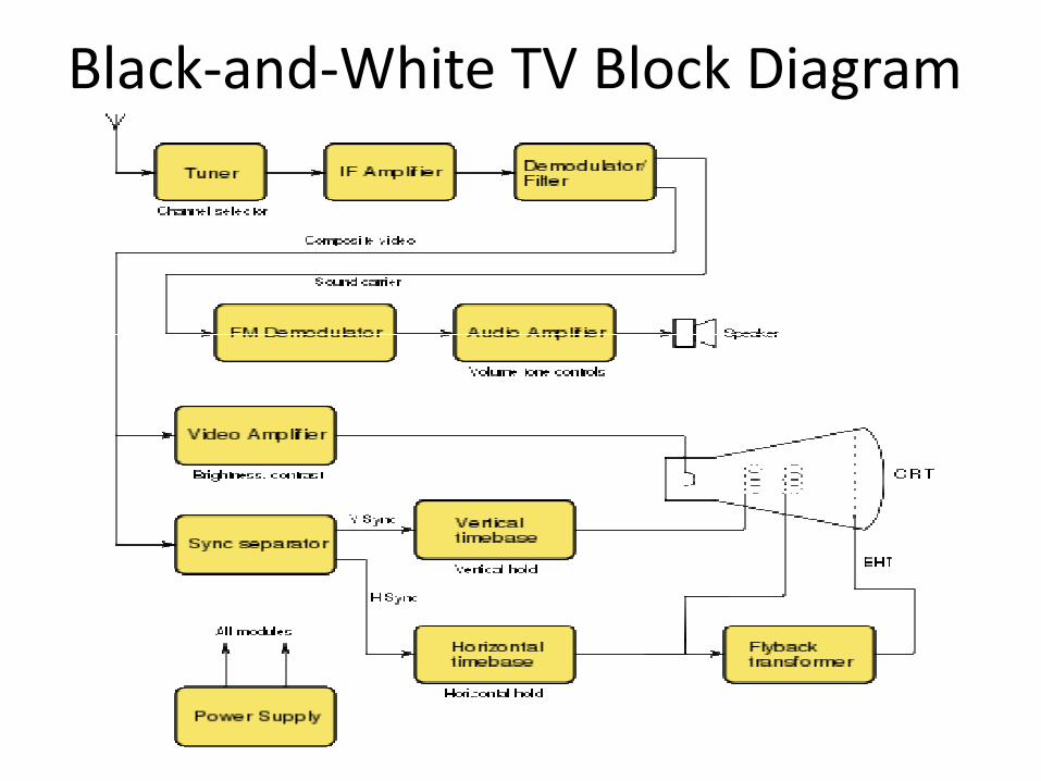
Black‐and‐White TV Block Diagram
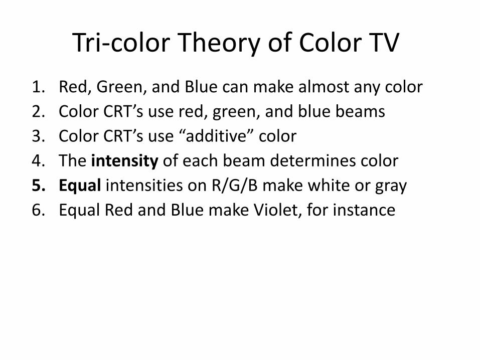
Tri‐color Theory of Color TVTri color Theory of Color TV1. Red, Green, and Blue can make almost any color2. Color CRT’s use red, green, and blue beams3. Color CRT’s use “additive” color
h i i f h b d i l4. The intensity of each beam determines color5. Equal intensities on R/G/B make white or gray6 E l R d d Bl k Vi l t f i t6. Equal Red and Blue make Violet, for instance

Color TV Block DiagramRF Demodulator Module Audio
Luminance Processing
Chroma Mixer/Demodulator
H-LockedAnd V Locked Color Subcarrier Oscillator
(Phase-Locked Loop to Burst Phase)
V-LockedBeam ScanOscillators
Color Space ConverterPowerSupplies

Newer TV: Digital Signal ProcessingA Tuner Module and a DSP Computer “Chip” Do Everything,
Except For CRT Beam Control or LCD Raster Control
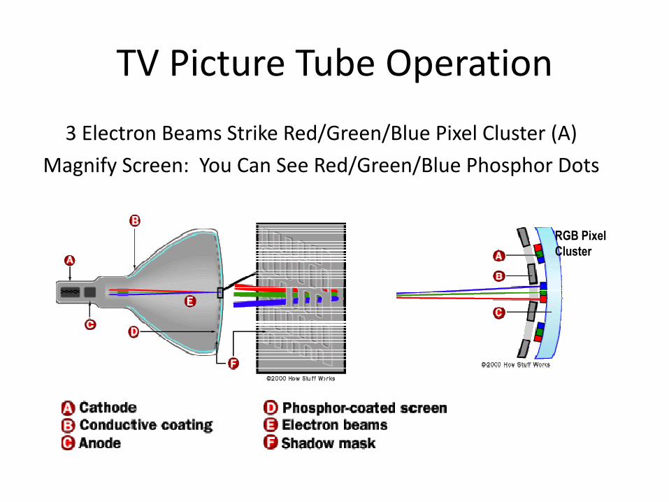
TV Picture Tube OperationTV Picture Tube Operation
3 Electron Beams Strike Red/Green/Blue Pixel Cluster (A)( )
Magnify Screen: You Can See Red/Green/Blue Phosphor Dots
RGB Pixel Cluster

TV Picture Tube Operation(These unfortunate color choices have nothing to do with R/G/B beams; they ( g y
apply to each of the red, green, and blue beams)
Electron Beams “Paint” the RGB Image on Tri‐color Phosphors, Left‐to‐Right.
Beam is Off During Dotted‐Red Horizontal Re‐Trace Back to Scan Next Line.
Beam is Off again during green Vertical Re‐Trace to Top

TV Picture Tube Side ViewTV Picture Tube Side View
Hi h V lt > 25kV
High Voltage Supply

TV Picture Tube Top Viewp
> 25kV H.V. Supply
Focus Anode
Focus Coils Cathode

CRT Cathode/Anode/CoilsF C il T C (Ali ) f h 3 RGB BFocus Coils Tune Convergence (Alignment) of the 3 RGB Beams
Cathode
Anode Focus CoilsAnode Focus Coils

TV Main ComponentsNew Flat Panel TV• LCD or Plasma Display
Old CRT TV
• Cathode Ray Tube (CRT)
• Display Power Supplies
• RF Tuner/Demodulator
• High Voltage Power Supply
• RF Tuner/Demodulator
• IR Remote interface
• Stereo sound amps
• Analog to digital con erters
• IR Remote interface
• Stereo sound amps
• Hs nc and Vs nc processors• Analog‐to‐digital converters
• DSP Image Computer
• Digital‐to‐analog Panel Driver
• Hsync and Vsync processors
• Y/C (luma/chroma) Separator
• Chroma DemodulatorDigital to analog Panel Driver Chroma Demodulator
• ACC (Auto Color Control)
• Color Space Converter
• H/V CRT drive amplifiers
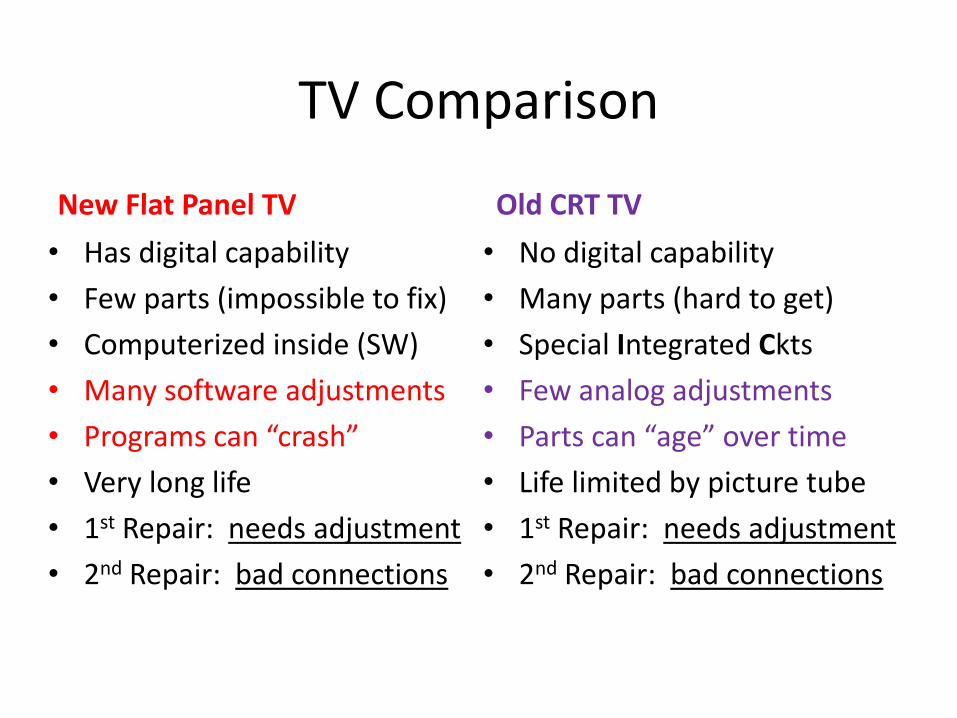
TV ComparisonTV Comparison
New Flat Panel TV Old CRT TVNew Flat Panel TV
• Has digital capability
• Few parts (impossible to fix)
Old CRT TV
• No digital capability
• Many parts (hard to get)Few parts (impossible to fix)
• Computerized inside (SW)
• Many software adjustments
Many parts (hard to get)
• Special Integrated Ckts
• Few analog adjustments
• Programs can “crash”
• Very long life
• Parts can “age” over time
• Life limited by picture tube
• 1st Repair: needs adjustment
• 2nd Repair: bad connections
• 1st Repair: needs adjustment
• 2nd Repair: bad connections

Television Tuner Module
“Baseband” Video Signal
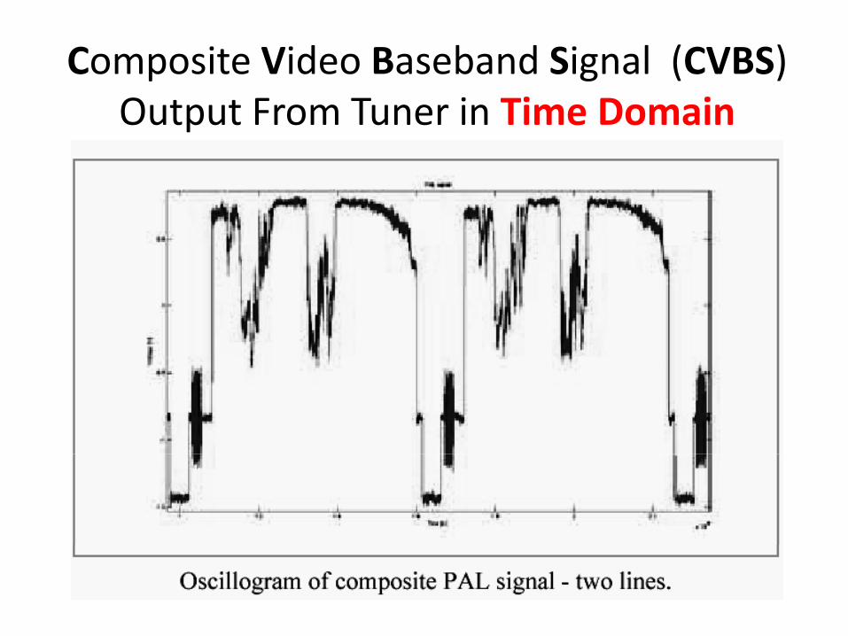
Composite Video Baseband Signal (CVBS)Output From Tuner in Time Domain

“Baseband” Video in Frequency Domain(Audio is Different Output from Tuner; Not Part of CVBS Output)
F S i d h lFrequency Spectrum per transmitted channel

CVBS “Baseband” Video FrequenciesCVBS Baseband Video Frequencies
1. Simple frequency‐selective filters can separate Color from B&W
– LPF = Low Pass Filters
– BPF = Band Pass Filter
HPF Hi h P Fil– HPF = High Pass Filter
– NotchF = Notch Filter
2. There is a problem because Chroma overlaps Luminance (B&W)p p ( )
3. Color can be wrongly detected as B&W detail, called “dot crawl”
4. B&W Luminance can be wrongly detected as “cross‐color”
5. All simple pass‐band filters have this problem
6. Special “Comb” Filters can minimize this problem
– Use Color Subcarrier “phase‐flipping” each line to cancel colorUse Color Subcarrier phase flipping each line to cancel color

“Multiburst” CVBS Test Signal is Helpful to Identify Filter Effects for Selected Frequencies

HPF and LPF to Separate Color (Chrominance) and Black‐and‐White (Luminance)

Multiburst Test Signal After LPF, Showing Elimination of High Frequencies

BPF and NotchF to Separate Color (Chrominance) and Black‐and‐White (Luminance)

NotchF Effect is to Eliminate Chroma Frequencies Shown as Missing Frequency “Burst” at 4.4MHz
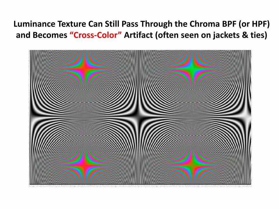
Luminance Texture Can Still Pass Through the Chroma BPF (or HPF) and Becomes “Cross‐Color” Artifact (often seen on jackets & ties)

Color Edges Can Sometimes Get Decoded as Black‐and‐White Detail ‐‐ Displayed as dots, or “Dot Crawl”

PAL Comb Filter Separates Color From Luminance (B&W) With Best Detail and Least Cross‐color

Luminance Resolution Chart = Picture DetailHigher Bandwidth (Frequency Response) Means More DetailHigher Bandwidth (Frequency Response) Means More Detail
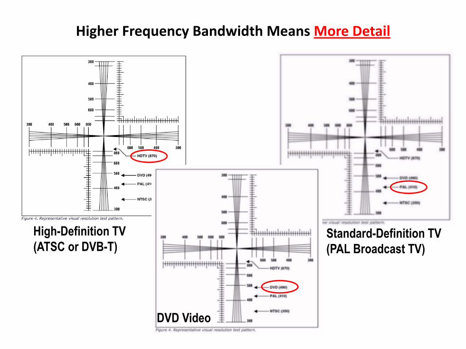
Higher Frequency Bandwidth Means More Detail
High-Definition TV(ATSC or DVB-T)
Standard-Definition TV (PAL Broadcast TV)(ATSC or DVB T) (PAL Broadcast TV)
DVD Video

PAL Colour Bar “Chroma Envelopes”Sinewave Amplitude is “Saturation” (low = pale; high = vivid)
Phase Difference from Color Burst Reference is “Hue” (Blue, Red, etc)

Detail of Color Burst Signal on CVBSUsed as Hue phase reference and auto color referenceUsed as Hue phase reference and auto‐color reference

PAL Colour Bar “Chroma Envelopes”Shaded areas are 4 418MHz Color Subcarrier SinewaveShaded areas are 4.418MHz Color Subcarrier Sinewave.
Sinewave Phase is “Hue”, Sinewave Amplitude is “Saturation”

PAL Colour Bars on OscilloscopePAL Colour Bars on Oscilloscope

“Chroma” C After Y/C Separation(Only Color Subcarrier Remains; Y is Gone)
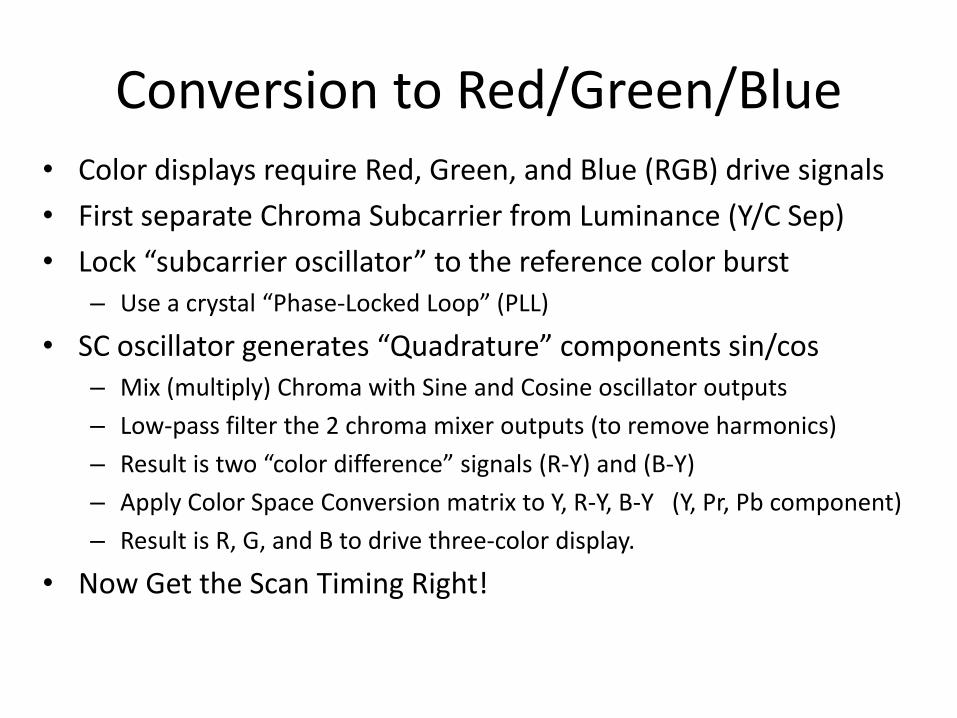
Conversion to Red/Green/BlueConversion to Red/Green/Blue • Color displays require Red, Green, and Blue (RGB) drive signals
i h b i f i ( / )• First separate Chroma Subcarrier from Luminance (Y/C Sep)
• Lock “subcarrier oscillator” to the reference color burst– Use a crystal “Phase‐Locked Loop” (PLL)Use a crystal Phase Locked Loop (PLL)
• SC oscillator generates “Quadrature” components sin/cos– Mix (multiply) Chroma with Sine and Cosine oscillator outputs
– Low‐pass filter the 2 chroma mixer outputs (to remove harmonics)
– Result is two “color difference” signals (R‐Y) and (B‐Y)
– Apply Color Space Conversion matrix to Y, R‐Y, B‐Y (Y, Pr, Pb component)pp y p , , ( , , p )
– Result is R, G, and B to drive three‐color display.
• Now Get the Scan Timing Right!

Color Decoding Block DiagramCVBS Y/C Y/(B Y)/(R Y) R/G/BCVBS >> Y/C >> Y/(B‐Y)/(R‐Y) >> R/G/B
Tuner D d l t
Right Audio
Left Audio
RF
Demodulator
CVBSCompositeVideo
Left Audio
Luma DelayY (Luma)
ComponentTo RGB
VideoYdelayed (Luma)
Red
Green
R
Y/C SeparatorChroma
Demodulator
C (Chroma) LPF
LPF
ColorSpace
Converter
(B-Y)
(R-Y)
Green
Blue
G
B
Color SCOscillatorBurst
SC R f
Sin(ωt)Cos(ωt)
“Component” Video
“Composite” Video
“RGB” Video
SC Ref
“S-Video”
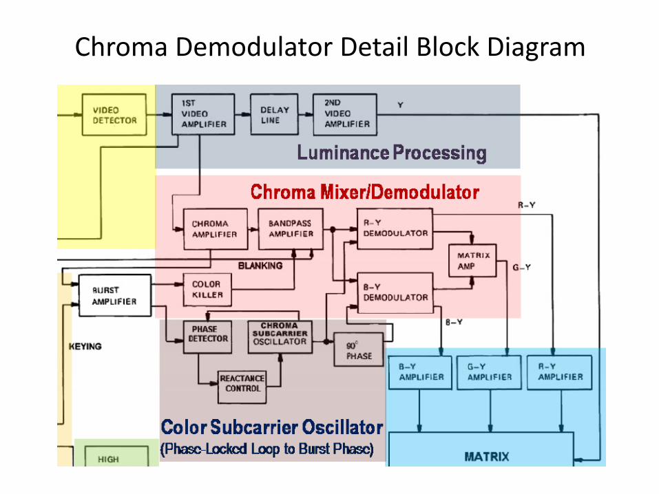
Chroma Demodulator Detail Block Diagram

PAL Colour Bars on TV “Vectorscope”Polar Coordinates: Angle shows Phase (Hue)Polar Coordinates: Angle shows Phase (Hue)
Radial Distance is Saturation
Red Magenta
Whi
teYe
llow
Cyan
Gree
nMa
gent
aRe
dBl
ueBl
ack
BlueYellow
W Y C G M R B B
R-Y
Colour BarsTV Test Screen
CyanGreen
TV Test Screen
y
B-Y
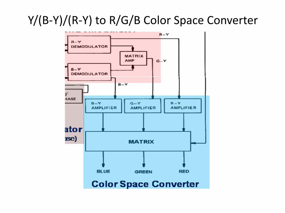
Y/(B‐Y)/(R‐Y) to R/G/B Color Space Converter

Decoding and Color Space ConversionCVBS >>> Y/Pr/Pb >>> R/G/BCVBS >>> Y/Pr/Pb >>> R/G/B
Y
R‐Y
B YB‐Y
“Component” Video“Composite” Video “RGB” Video

Horizontal & Vertical Drive Oscillators“Locking” Horizontal and Vertical Beam Sweep Generators

Vsync and Hsync Timing for Electron Beam Scan of Phosphors

Detail of HSync Signal on CVBSStarts Horizontal Synchronization of Each Scan LineStarts Horizontal Synchronization of Each Scan Line
Active Video
Active Color Burst Reference
Video
Sync Tip Backporch
Specifications differ by Television System (PAL or NTSC)
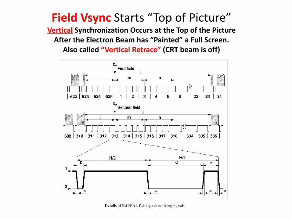
Field Vsync Starts “Top of Picture” Vertical Synchronization Occurs at the Top of the PictureVertical Synchronization Occurs at the Top of the Picture
After the Electron Beam has “Painted” a Full Screen.Also called “Vertical Retrace” (CRT beam is off)

Horizontal & Vertical Drive OscillatorsH/V Oscillator Sweep Timing is Now “Locked” to Incoming CVBS

CRT Geometric Distortion Adjustments
Horiz Width
Horiz. Position
Vertical Height
“Barrel”
Horiz. Width g
“Pincushion” Vertical Position
“Tilt”

Matrix or “Raster” DisplaysMatrix or Raster Displays1. LCD or Plasma2 B th h fi d “ ti ” i l l ti h 1024 7682. Both have fixed “native” pixel‐resolution, such as 1024x7683. Both display many resolutions, but work best at native4. Both are better for digital video than CRTg5. Both have built‐in scan driver I.C.’s6. NO geometric distortions like CRT (unless rear‐projection)7. LCD uses low‐voltage only, Plasma has high voltage8. LCD pixels are always on, unlike CRT phosphor scan9. Plasma and LCD are much brighter than CRT9. Plasma and LCD are much brighter than CRT
10. LCD has better color and longer life than CRT (or Plasma)

High LCD/Plasma Pixel‐Resolution Means More Detail
High-Definition TV(LCD or Plasma
Standard Picture Tube Broadcast (PAL) TV (LCD or Plasma,
at 1024x768 pixels)Broadcast (PAL) TV
CRT BestCRT BestResolution

Digital TV Decoding ‐ Block DiagramRF >> MPEG >> Y/C /C (4:2:0) >> R/G/B digitalRF >> MPEG >> Y/CR/CB (4:2:0) >> R/G/B digital
DVB‐T Tuner D d l t
Right Digital Audio
Left Digital Audio
RF
PAL Countries Use DVB-T for HDTVDemodulator
Digital MPEGStream
PAL Countries Use DVB-T for HDTVNTSC Countries Use ATSC for HDTV
MPEG2Decoding
Y (8-bit digital)Pixel
ResolutionC t
Red (10-bit)
LCDDecoding
(FrequencyDomain to
Time Domain
CR = R-Y (8-bit digital) Converter
andColorSpace
C t
Green (10-bit)or Plasma
DigitalPanel Drivere o a
Conversion)Converter
andGamma
Correction
Blue (10-bit)CB = B-Y (8-bit digital)Interface
“Component” 4:2:0 Digital Video
Digital “RGB” at Panel Pixel Rate