telos z/ip one - avc.hr · telos z/ip one intelligent zephyr ip codec with agile connection...
TRANSCRIPT

TELOS Z/IP ONEIntelligent Zephyr IP Codec with Agile Connection Technology™
USER’S MANUAL
Manual version 1.1 for software version 1.0.15 and later10 August 2011

Z/IP ONE Manual © 2011 TLS Corporation. Published by Telos Systems/TLS Corporation. All rights reserved.
Trademarks Telos Systems, the Telos logo and Z/IP ONE are trademarks of TLS Corporation. All othertrademarks are the property of their respective holders.
Notice All versions, claims of compatibility, trademarks, etc. of hardware and software products not made by Telos mentioned in this manual or accompanying material are informational only. Telos Systems makes no endorsement of any particular product for any purpose, nor claims any responsibility for operation or accuracy. We reserve the right to make improvements or changes in the products described in this manual which may affect the product specifications, or to revise the manual without notice.
Warranty This product is covered by a two year limited warranty, the full text of which is included in this manual.
Updates The operation of the Z/IP ONE is determined largely by software. We routinely release new versions to add features and fix bugs. Check the Telos web site for the latest. We encourage you to sign-up for the email notification service offered on the site.
Feedback We welcome feedback on any aspect of the Z/IP ONE, or this manual. In the past, many good ideas from users have made their way into software revisions or new products. Please contact us with your comments.
Service You must contact Telos before returning any equipment for factory service. We will need the serial number, located on the back of the unit. Telos Systems will issue a Return Authorization number which must be written on the exterior of your shipping container. Please do not include cables or accessories unless specifically requested bythe technical support engineer at Telos. Be sure to adequately insure your shipment for its replacement value. Packages without proper authorization may be refused. US customers please contact Telos technical support at +1-216-622-0247. All other customers should contact your local representative to make arrangements for service.
We support you...By Phone / Fax: You may reach our 24/7 Support Team anytime around the clock by calling +1-216-622-0247.
For billing questions or other non-emergency technical questions, call +1-216-241-7225 between 9:30 AM to 6:00 PM USA Eastern Time, Monday through Friday.
Our fax is +1-216-241-4103.
By E-Mail: Technical support is available at [email protected].
All other inquiries at [email protected].
Via World Wide Web: The Telos Web site has a variety of information which may be useful for product selection and support.
The URL is www.Telos-Systems.com
10 9 8 7 6 5 4 3 2 1
II |

Telos Systems USATelos Systems
1241 Superior Avenue E
Cleveland, OH 44114 USA
+1-216-241-7225 (phone)
+1-216-241-4103 (fax)
+1-216-622-0247 (24/7 Technical Support)
Notices and Cautions
CAUTION:THE INSTALLATION AND SERVICE INSTRUCTIONS IN THIS MANUAL ARE FOR USE BY QUALIFIED PERSONNEL ONLY. TO AVOID ELECTRIC SHOCK, DO NOT PERFORM ANY SERVICING OTHER THAN THAT CONTAINED IN THE OPERATING INSTRUCTIONS UNLESS YOU ARE QUALIFIED TO DO SO. REFER ALL SERVICING TO QUALIFIED PERSONNEL.
WARNING: TO REDUCE THE RISK OF ELECTRICAL SHOCK, DO NOT EXPOSE THIS PRODUCT TO RAIN OR MOIS-TURE.
USA CLASS A COMPUTING DEVICE INFORMATION TO USER. WARNING: This equipment generates, uses, and can radiate radio-frequency energy. If it is not installed and used as directed by this manual, it may cause interference to radio communication. This equipment complies with the limits for a Class A computing device, as specified by FCC Rules, Part 15, Subpart J, which are designed to provide reasonable protec-tion against such interference when this type of equipment is operated in a commercial environment. Operation of this equipment in a residential area is likely to cause interference. If it does, the user will be required to eliminate the interference at the user’s expense. NOTE: Objectionable interference to TV or radio reception can occur if other devices are connected to this device without the use of shielded interconnect cables. FCC rules require the use of shielded cables.
CANADA WARNING: “This digital apparatus does not exceed the Class A limits for radio noise emissions set out in the Radio Interference Regulations of the Canadian Department of Communications.”“Le present appareil numerique n’emet pas de bruits radioelectriques depassant les limites applicables aux appareils numeriques (de Class A) prescrites dans le reglement sur le brouillage radioelectrique edicte par le ministere des Communications du Canada.”
This symbol, wherever it appears, alerts you to the presenceof uninsulated, dangerous voltage inside the enclosure –voltage which may be sufficient to constitute a risk of shock.
This symbol, wherever it appears, alerts you to importantoperating and maintenance instructions. Read the manual.
| III


We support you... . . . . . . . . . . . . . . . . . . . . . . . . . . . . II
A letter from our CEO . . . . . . . . . . . . . . . . . . . . . . . . . . VII
1 Introduction 1
2 QuickStartGuide 3
3 Installation 7
4 TheUserInterface&Setup 11
The Front Panel Controls . . . . . . . . . . . . . . . . . . . . . . . . . 11
5 TheWebInterface 23
6 MakingConnectionsWithOtherUnits 31
7 TheZ/IPServer 35
8 GroupsandDirectoryServices 37
9 WhenAnITDepartmentIsNotAvailable 39
10 TheParallelPortAndContactClosures 49
11 AudioCodingReference 53
12 MobileNetworkDevices 65
13 UsingTheFieldUpgradeOption 67
14 Z/IPONEAudioSpecifications 71
15 WarrantyAndApplicationCaution 73
16 SafetyNotification 75
z/ip one preliMinAry MAnuAl | V
Table of Contents


A leTTer froM our Ceo | VII
A Letter from our CEO...“What if?” A singularly great question, because it opens the door to so many other questions and ideas. Those who ask it are sometimes called dreamers, as if that were somehow bad, but history has often proven dreamers to be the avatars of new and exciting things.
“What if?” was the query asked by Steve Church that led to the start of Telos Systems. In 1984, Steve – then a young broadcast engineer and part-time talk show host – won-dered whether emerging Digital Signal Processing (DSP) technology might be useful to clean up the terrible caller audio then the norm at radio stations. The result of asking it was the Telos 10, the world’s first digital telephone hybrid, a product that changed the face of radio forever.
Looking back at Telos history, “What if?” is found at the root of many more technologies broadcasters have since made ubiquitous. “MP3 bit rates are perfectly matched to the bandwidth of ISDN; what if we combined them?” “What if we built a box that let radio stations stream audio on the Internet?” “What if we could use Ethernet to treat audio as data and move it around the radio station in real time?” (By the way, if you recognized the answers to those questions as the Zephyr ISDN codec, AudioActive MPEG encoder and Livewire IP-Audio standard, give yourself a cookie.)
Today, as technology roars ahead, we’re constantly seeking new ways to apply it to the problems of everyday broadcast-ing. Voice over IP (VoIP) is particularly compelling for its ability to packetize high-quality phone calls and direct them anywhere in the broadcast plant using ubiquitous, standard Ethernet as a backbone. A new digital tech called AEC (Advanced Echo Cancellation) is helping to literally
eliminate the age-old problem of feedback in open-speaker environments. And the prize of using the public Internet for remote connections as reliable as those of switched circuits is within broadcasters’ grasp, thanks to ever more sophisti-cated coding algorithms.
Pioneering ideas aren’t limited just to technology, though. We believe that investing in people pays off big, so we’ve assembled the largest R&D team in the industry, a talented staff of engineers, scientists and broadcast professionals. We’re also the first and only broadcast equipment maker with a 24/7 support team ready to offer assistance any time of the day or night. As they say, radio never sleeps – so neither do we.
As Telos navigates its third decade in broadcasting’s choppy waters, the culture of innovation and creativity that propelled Steve in the early days still guides us today. We’re still in love with radio, still turned on by new technology, still driven to ask “What if?” If you’re reading this, you are too — for which we thank you, from the bottom of our hearts.
Michael “Catfish” Dosch
CEO


| 1
1 introductionCongratulations on your purchase of the Telos Z/IP ONE! This unit achieves a new level in IP Audio transmission at a very attractive price. It is a one RU unit intended to be used with a microphone directly, or an external mixer for remote broadcasts, or anywhere space is at a premium.
The Telos Z/IP ONE combines RTP/UDP and TCP/IP streaming capabilities with MPEG coding to deliver broadcast-quality audio over IP connections. Z/IP ONE employs sophisticated new technology to achieve superb audio quality over IP links such as the Internet and mobile IP services. The Z/IP ONE utilizes ACT™ - Agile Connection Technology to continuously adapt to network conditions, minimizing the effects of packet loss, varying bandwidth, and jitter that can occur on these networks by means of sophisticated error detection and concealment, dynamic buffering and other techniques that work together to provide reliable IP audio connections.
The Z/IP ONE has an impressive list of features including:
♦ Analog Line Pro or Microphone input levels.
♦ 15 volt Phantom power for direct use with condenser microphones.
♦ Supports transmission bit rates from 8 kbps to 2304 kbps.
♦ User-friendly, graphical OLED screen and User Interface.
♦ Real-time metering and connection status display screen.
♦ Context-sensitive on-screen help available at a touch of a button.
♦ EBU N/ACIP (Audio Contribution over IP) and SIP compatible for interoperability with other third party codecs.
♦ Backward compatible with thousands of Telos Zephyr Xstreams in the field.
♦ Built-in web server for configuration and remote control.
♦ Wireless connection through Wi-Fi and 3G/4G/EVDO modems (WIFI modem included).
♦ Livewire™ inputs and outputs.
♦ Separate LAN and WAN Ethernet ports simplify isolation of your LAN from the internet.
♦ The ability to register with a “directory server” (ZIP server). This allows establishing a connection even when located behind NATs and firewalls without knowing the other party’s IP address.
♦ Router Mode allows using Z/IP ONE as a gateway to access the Web.


| 3
2 Quick Start Guide
After unpacking your Z/IP ONE you can quickly get up and running using this simple guide. The steps involved are: attach cables, configure the network interface, configure the Z/IP server settings, connect to the network, adjust the audio settings and make a test call.
To test the Z/IP ONE, you’ll need:
1. Headphones2. Dynamic Microphone (optional)3. AC power cord for your country (included) and an AC mains outlet (100-240 Volts)4. An RJ45 patch cord (included)5. An Ethernet Local Area Network with:6. A DHCP Server, and 7. A connection to the Internet
2.1UserInterfaceBasicsThe Z/IP ONE uses the same OLED display for status and metering that it does for the user interface. After a short period of time the display will revert back to the Status Screen menus. There are six status menus available; Z/IP ONE will remember the last menu item you were viewing. The status menu options are:
1. Meters/Connection Status2. Current or Last connection details3. LAN interface information4. WAN interface information5. WiFi interface information6. EVDO/UTMS interface information
Turning the Z/IP One’s Control knob will scroll through these screens.
Pressing the key once will bring up the main menu (pictured above, right). Rotating the Z/IP ONE’s
control knob moves through the various screens pressing the knob , selects the highlightedmenu selection.
You can get general help at any time with the HELP option from main menu. To get context-specific help
press the key.
Step 1: Attach Cables to the Unit
Attach the power cable, and your audio cables (two pairs of XLR cables). Do not connect the unit to your network at this time.

4 | Section 2
We recommended that you do not connect the unit to your network until you configure the network interface through the front panel. This avoids the possibility of the unit having the same IP address as another device on your network. Duplicate IP addresses are a sure source of weird problems, not to mention unpleasant calls from the IT department.
Step 2: Configure the Network Interface
Once power is connected to the unit the blue front-panel LED will flash while the unit starts up, followed by the main menu. When the menu appears, navigate to the Setup option by rotating the control knob. Press the control knob to select this option. Using the same “rotate – press” process, select the Network menu.
In the Network sub-menu select LAN Interface. Now scroll down to the DHCP selection and change it to On. Scroll to, and click Activate Settings! to start using the new settings.
Use the control knob to navigate to the field you want to change then press to edit the field. While you are editing a field, use the keypad to enter the data. If an address has only 1 or 2 digits use leading zeros to pad the number (e.g. use “003” if the desired entry is “3”. You can rotate the knob counter-clockwise to re-enter a mistake. Press the knob to save your changes, or ESC to discard them.
Step 3: Configure the Z/IP ONE Server Settings
At the Setup menu (below), select the ZIP Server option.
The following screen is displayed:
On this screen you will enter a Device/Unit name for your unit, and a Group name to which this unit belongs as well as a Group Password for that Group. For this Quick Start you should enter public for the Group name as well as for the Group password. The public group is a default group that anyone can use. You may create a new group at any time. Generally a group represents your organization .
The Device/Unit name, together with the Group name forms the “phone number” (i.e. “identity”) for the unit. This is the “number” you give out and how others can call your Z/IP regardless of what IP address you have at the moment.
The Device/Unit name must be unique within your Group. If the name you happen to select is already in use, the server will return a unique name by appending a number to the name. If this unique name is acceptable you may use it; otherwise try a different name.
The Device Visibility option determines whether your unit will be visible to others in the directory listing. There are three choices here. The first, “visible to all”, lets anyone see the name and the group of your Z/IP. The second, “group visible,” allows only members of your group (those that know the group password) to see your Z/IP. The last option, “hidden,” is just that; your Z/IP does not appear in any directory listings. Please note that this option only affects the directory listing. Remote users will still be able to call you regardless of the choice you make here (just like you continue to get phone calls during dinner time even if you have an unlisted number).

QuiCK STArT GuiDe | 5
The Listen Port is a TCP/IP port for your device to listen on if you are using “port forwarding” on your NAT. This port determines what port the Z/IP will use to accept messages from others. The default value of 0 tells the Z/IP to assign a port itself. This setting works best for most cases. You may need to change this value if you are behind a very restrictive NAT and others have difficulties reaching your device. Section 9.1 describes more on port forwarding should you need to learn more, but the default settings are appropriate for most uses.
Press ESC twice to return to the Status screen.
Step 4: Connect to the Network
With configuration completed, you are now ready to connect to the network. Plug your network cable into the Ethernet jack on the back of the unit labeled Livewire LAN. This is a standard 100 Base-T connector. After connecting to your LAN, check the Link indicator on the left side of the Status Screen: This indicator will be solid if you are connected to an active network.
The Z/IP indicator on the status screen will also turn solid after a few moments and indicates that you have a connection to the Internet, and that the unit is in contact with the Z/IP server. If either of these indicators is not solid, verify your Ethernet settings on the network menu. Check with your IT department to ensure your network has a DHCP server (or alternatively to give you an IP Address, Subnet mask, Gateway and DNS server for you to enter in the Setup->Network->LAN menu) or have a look at the “When you don’t have an IT department” section in this manual.
Step 5: Configure the Audio Input/Output Settings
Select and click on the Audio I/O option on the Main Menu screen (press ESC a few times, if you’re not on the Main Menu screen):
Select the appropriate options depending on your audio connections (Microphone if you are using a dynamic microphone).
Press ESC twice to exit when finished.
Step 6: Make a Test Call
You are now ready to make a test call to the Z/IP test line at Telos. Press the AUTO button. The call screen will be displayed:
Scroll through the “buddy list” on the screen to the “Telos Line” or “Testline” entry. You should see a filled dot next to the name, indicating that it is online. Depress the control knob to connect. The Status screen will re-appear and you should see the Connect and Receive Lock indicators turn solid, and see level meters on the Receive bargraphs. When you speak into your microphone you should see meter activity on the Send meters.


| 7
3 installation
3.1RackMountingtheStudioUnitThe Z/IP ONE mounts in a 1RU space in a standard 19” rack. The Z/IP ONE does not have an internal fan, and does not have any special requirements for space above and below the unit. As long as you keep the stirred air in the rack between 0 and 40 degrees Celsius (32 to 104 degrees Fahrenheit) with a relative humidity of 0 to 98% (non-condensing) the unit will operate as described.
3.2PowerInstall the power cord included with the Z/IP ONE in the marked AC power connector located in the rear of the unit. The internal universal switching supply will accept 100– 240 VAC (50-60 Hz) input. You should see blue front panel LED flash to indicate the unit is booting. Subsequently, the main menu will appear. This process can take about 90 seconds.
3.3AudioInputsAudio XLR Pinout (balanced analog)
PIN DESCRIPTION
1 Ground
2 Signal + Input
3 Signal - Input
Install the left and right analog audio cables in the female XLR connectors marked LEFT and RIGHT on the rear panel. The analog audio section accepts audio input with a peak level of +22dBu. In the Audio I/O ->Input mode Left or Right menu option you can configure each audio input can be configured for the follow-ing settings:
♦ Line (+4 dBu nominal)
♦ Microphone
♦ Mic + Phantom Power
Mic. Gain TrimThere is a mic gain trim adjustment option in the Setup -> Audio I/O menu for each input that can be used to add additional gain when that input is set to Microphone or Mic + Phantom Power. This setting is ignored when the input is set to the Line setting. Gain should be adjusted so that the microphone reaches your desired level on peaks.

8 | Section 3
3.4AudioOutputs(analogbalanced)Audio XLR Pinout
PIN DESCRIPTION
1 Ground
2 Signal + Output
3 Signal - Output
The audio outputs are balanced at +4 dBu with 18 dB of headroom (i.e., clips at +22 dBu)
3.5NetworkInterfaces–Livewire/LAN&<…>10/100WANThe network interfaces are Ethernet twisted pair 100BASE-T connectors. Use a CAT5e or CAT6 network cable. The standard pinout for an RJ45 style 8-Pin/8-Position miniature modular jack when used for 10/100BT Ethernet Jack is:
PIN FUNCTION
1 Transmit +
2 Transmit -
3 Receive +
4 Unused
5 Unused
6 Receive -
7 Unused
8 Unused
3.6USBPortsAttach any of the supported USB-network extension devices to these ports. Use of unapproved device may cause unpredictable and unacceptable results – therefore we recommend against such experimentation. The pinout of the standard USB connector used on the Z/IP is:
PIN FUNCTION
1 +5 Volts
2 Data –
3 Data +
4 Ground
3.7ParallelControlThe DB25 connector on the back panel provides contact closure (close-to-ground) inputs and outputs. There are 8 open-collector outputs, and 8 open collector inputs, each configurable from the Settings menu in the user interface. The DB25 connector is pinned-out as follows:

inSTAllATion | 9
PIN FUNCTION
1 +5 Volts DC 400 mA max
2 Output 0
3 Output 1
4 Output 2
5 Output 3
6 Output 4
7 Output 5
8 Output 6
9 Output 7
10 No Connection
11 No Connection
12 No Connection
13 No Connection
14 Input 0
15 Input 1
16 Input 2
17 Input 3
18 Input 4
19 Input 5
20 Input 6
21 Input 7
22 Not Connected
23 Not Connected
24 Not Connected
25 Ground
See chapter 10 below for more detailed information on the Contact Closure operations.


| 11
4 The user interface & Setup
TheFrontPanelControls
Headphone Control KnobThis is a volume control. It also has a push-to-mute function. Pushing this button will mute the headphone audio. Pushing a second time will un-mute it.
Main Control Knob
Rotating the Z/IP ONE’s control knob moves the cursor. It also has a push-to-click function; pressing
the knob , selects the highlighted menu selection.
ESC ButtonThis button escapes from the currently selected menu or dialog screen. While in edit mode, pressing cancels any edits and leaves the field unchanged.
The Number Pad The dial pad is used to enter data in edit fields. If the field accepts only numeric data (or IP addresses) then pressing the buttons will enter the number pressed.
Other fields accept alphanumeric strings. In these fields the buttons cycle though the alphabetic characters in uppercase then lowercase then the numeric value. The 1, * and # buttons allow you to enter special characters.

12 | Section 4
CHARACTERS ENTERED
1 <space> : / @ 1
2 A B C a b c 2
3 D E F d e f 3
4 G H I g h i 4
5 J K L j k l 5
6 M N O m n o 6
7 P Q R S p q r s 7
8 T U V t u v 8
9 W X Y Z w x y z 9
* * ( ) = %
# # . , - _
The Connection ButtonsThe Z/IP ONE has 3 buttons on the very right side for setting up and dismissing connections, labeled “AUTO, CONN and DISC”. The function of these short-cut keys is as follows:
♦ AUTO Button performs the same action as choosing AUTODIAL from the main menu – it is a shortcut key. Press the AUTO button to bring up your “Buddy List”. This screen displays the current status of the other Z/IPs so you can see if they are available before you call. Pressing Auto while in the Buddy List will immediately dial the Z/IP ONE.
♦ CONN Button: A manual dialing screen will be shown for you to enter the name of the unit youwish to call directly.
♦ DISC Button: Press the DISC button to disconnect any established connections. You will be prompted to confirm the disconnect. Pressing DISC twice causes Z/IP ONE to disconnect immediately.
Getting Help!Context sensitive Help is available at any time by pressing the button. General help can also be accessed by choosing HELP from the main menu.
4.1TheUserInterfaceandMenuSystemThe Z/IP ONE will time out to the status screen showing meters and status information after a period of
inactivity. Pressing the button will enter the menu system. Rotating the control knob moves
from option to option while pressing it will select the currently highlighted item. While in a menu,
pressing will back you up one level. Repeated presses will take you to the main menu.From the Main Menu (below) you can access the Status, Phonebook, Audio I/O, Setup, Help, Status, Help, and Autodial sub-menus.

THe uSer inTerfACe & SeTup | 13
The Audio I/O Menu
The Audio I/O menu gives access to the various settings related to audio into and out of the device.
♦ Audio Input Source can be set to either of the following:
♦ Analog XLR Inputs or
♦ Livewire (the Livewire stream to be used is set in the Setup -> Network -> Livewire menu).
♦ Choose Analog to select the Analog XLR as the audio input source. Choose Livewire to use the Axia Networked Audio interface as the audio source. The Analog outputs are always active.
About Livewire: If you decide to use the Livewire input, you will also need to choose a Livewire input stream in the Setup/Network/Livewire menu.
Livewire output is always enabled provided a Livewire output stream number has been selected in the Network/Livewire page.
♦ Input mode Left & Input mode Right adjusts the analog inputs and has the following settings:
♦ Line (+4 dBu nominal)
♦ Microphone
♦ Mic + Phantom Power (enables phantom power for that input)
♦ Mic Gain Trim can be adjusted from 0.0 to 22.5 dB
♦ Transmit Mode: Choose between Stereo or Mono L+R. Stereo is the default.
♦ Audio Loopback: Choose between OFF, PCM Direct, Encoded.
Setup Menus
The Setup menu contains 6 sub-menus and one direct changeable option as follows:
♦ Streaming Interface allows choosing the Ethernet or other interface that will be used to communicate with another codec. Normally this would be the WAN interface. The options are:
♦ LAN Port
♦ WAN Port

14 | Section 4
♦ WiFi/WLAN (appropriate USB stick must be installed)
♦ UMTS/EVDO (appropriate USB stick must be installed)
♦ The Setup -> Network Sub-menu has one menu item and the following sub-menus:
♦ The WAN Interface menu sets the following options for the WAN RJ-45 on the back of the unit:
♦ WAN IPaddress - IP address for this interface
♦ WAN Netmask –Subnet Mask for this interface
♦ WAN Gateway IP – Gateway Router IP address for this interface
♦ WAN DNS Server IP – DNS Server IP address for this interface
♦ WAN DHCP- (Off or On)
♦ Activate Settings - (accepts the above settings and restarts the network interface)
♦ The LAN Interface menu has the following options:
♦ LAN IPaddress - IP address for this interface
♦ LAN Netmask –Subnet Mask for this interface
♦ LAN Gateway IP – Gateway Router IP address for this interface
♦ LAN DNS Server IP – DNS Server IP address for this interface
♦ LAN DHCP - (Off or On)
♦ Activate Settings! - (accepts the above settings and restarts the network interface)
♦ The Livewire menu has the following options
♦ Select LW input stream: This list box shows the available Livewire streams in your network. After boot-up it may take a few seconds until all available streams have been detected. Browse to the desired stream to select it as your Livewire input.
♦ LW Output Stream number: Enter 0 to disable Livewire output. Enter a stream number inthe range 1 – 32000 to generate a Livewire stream. This stream will always be active.
♦ To actually use the selected Livewire input stream as your audio input you must also change your audio input device in the Audio menu to “Livewire”.
♦ The SIP Server sub-menu allows you to use your organization’s SIP server to make calls. This is optional in most cases. Contact your SIP server administrator for the values to enter in these fields, or leave them blank to not user your own SIP server.
♦ Registrar Hostname (allows entry of alphanumeric text)
♦ Registrar User Name (allows entry of alphanumeric text)

THe uSer inTerfACe & SeTup | 15
♦ Registrar Password (allows entry of alphanumeric text)
♦ Activate settings (Accepts the above settings)
♦ The Wifi/WLAN menu has the following fields (String = alphanumeric text, Hexnum = Hexadeci-mal numeral [digit-values of 0-F]):
♦ Encryption Method – WEP-String, WEP-Hexnum, WPA/WPA2-String, WPA/WPA2-Hexnum,
♦ ESSID Network Name
♦ Pwd String/Hex number (password as text string or hexadecimal number)
♦ Activate Settings! (accepts the above settings)
♦ The UMTS/EVDO sub-menu has the following items:
♦ Country (Germany, USA, or “Use Dial Number)”
♦ Protocol (CDMA or GPRS)
♦ Dial Number (allows entry of a numeric string)
♦ PIN Number (allows entry of a personal ID number)
♦ Account Name (allows entry of alphanumeric text)
♦ Account Password (allows entry of alphanumeric text)
♦ Provider URL (allows entry of a valid URL)
♦ Activate Settings! (accepts the above settings)
Router Mode – (has the following choices: Off and Between LAN and StreamIfc (short for “streaming interface). When Router Mode is off, the Ethernet ports are kept completely separate. When it is enabled, the Z/IP ONE creates a bridge between the LAN and whichever interface is selected for streaming.
♦ The Setup -> Audio Codec menu allows the user to change various settings related to the audio and transmission quality as well as select the appropriate compression scheme.
♦ Profile allows the Z/IP ONE to make codec decisions based on the goal displayed. If you choose “User Setting,” the following settings are used instead.
♦ Encoding Mode. The Z/IP ONE supports AAC-ELD, AAC-HE, AAC, HE-AAC-V2, HELD-AAC, AAC-LD, G711, G722 and 16, 20 & 24 bit PCM.
For more on the advantages and disadvantages of each, and typical bit rates, see Section 11.

16 | Section 4
♦ Bitrate Maximum and Bitrate Minimum: These parameters allow you set limits on the range of bitrates available to the Z/IP ONE’s Agile Connection Technology (ACT) intelligence when adjusting for various network defects. The wider the range, the greater the flexibility of the encoder to “fine-tune” your connection and audio fidelity. Your choice of codec will affect the available range of usable rates. The more you restrict this range the more consistent the audio quality will be, but with less ability to accommodate bad network conditions.
♦ Maximum Buffer and Minimum Buffer These two numbers specify the minimum and maximum decoder buffering in milliseconds. For optimum performance you should set these values to 0 ms and Unlimited. Note that if you change the buffering while a call is in progress you will be notified that the changes will only take effect after the call is recon-nected. Furthermore, the buffering only applies to MPEG codec modes but not to G.711, G.722 and PCM.
The total delay in a given direction of transmission will be the algorithmic delay of the particular algorithm being used in that direction, plus the current buffer setting (deter-mined by these values and Z/IP ONE’s ACT intelligence).
♦ The Layer-2 Payload Type field is for use with Real-time Transport Protocol (RTP) audio streams and the MPEG Layer 2 codec. While many players support the dynamic payload type (96), some require that the payload is set to MPEG Audio (14). Leave this setting on “96 - Default” unless you are having trouble with this exact scenario.
♦ The Setup->System submenu contains settings for general system options.
♦ Autoanswer - If Autoanswer is turned on, the Z/IP ONE will accept any incoming connec-tion. If autoanswer is off, the user will be prompted to accept or reject all incoming calls.
♦ Display Contrast sets the brightness of the screen. Turning the contrast down can extend the life of the frontpanel display.
♦ Frontpanel Speaker - choose which sounds are played during operation, or disable the internal speaker
♦ Redial Mode - If a call fails abnormally, this setting determines how many times the Z/IP ONE attempts to reestablish the call (if any)
♦ Display Dim Timeout - Enables a ‘screensaver’ that turns the contrast very low until any key or knob is used. Use this to extend the life of the display if the Z/IP ONE is not moni-tored via the frontpanel
♦ Remote ctrl password - This is the password used to access the Z/IP ONE’s configuration webpages

THe uSer inTerfACe & SeTup | 17
♦ NTP Server IP/Name - Specifies a Network Time Protocol server to use to set the time and date on the Z/IP ONE. Time and date are used on status displays and for timestamping logs for troubleshooting.
♦ The Setup->Software submenu allows you to choose between two different versions of Z/IP ONE software that may be installed. The last option, Reset to Defaults & Reboot!, will erase all custom settings and buddy list entries. When the Z/IP ONE reboots, it will have the same settings it had when it originally came from Telos.
♦ The Setup->Parallel Port submenu shows the settings and current state of the input and output General Purpose I/O pins. These pins may be either on the physical parallel port on the back of the Z/IP ONE, or virtual pins on Livewire GPIO.
♦ Input Bit 0-7 - Sets the Z/IP ONE’s response to toggling an input pin. See Chapter 10 for more information.
♦ Output Bit 0-7 - Sets what status information is reflected on each of the output pins. See Chapter 10 for more information.
♦ Bit 0..3 GPI Src - The Z/IP ONE’s 8 GPIO signals can be on the parallel port, or over Livewire. Since Livewire GPIO comes in bundles of 5 inputs and outputs, the Z/IP ONE uses the first four pins of two separate Livewire GPIO addresses. If a GPI Src is specified here, the first 4 inputs are taken from this Livewire GPIO port. Livewire GPOs are always present.
♦ Bit 4..7 GPI Src - The Livewire GPI Src for bits four through seven. Leave this field blank to use the parallel port for GPIO inputs.
♦ The Setup->Z/IP Server menu allows the user to select which Z/IP server to use, and how the Z/IP ONE is represented on that server.

18 | Section 4
♦ Device/Unit name: Use the keypad to enter a unique name for your Z/IP. You will share this name with your peers so they can see your online status and call you. Don’t worry if you pick a name that another user has already chosen: The Z/IP server will append a number to your name and display it accordingly.
♦ Group name: Use this field to register with a particular group that has been created on the Z/IP server. The default is “public” which allows your Z/IP to be contacted by anyone in the network. If you have created a private group on the server, enter the name here.
♦ Group password: The default is “public” for the public group. If you are registering with a private group, enter the password here.
♦ Device Visibility: Choose whether the Z/IP ONE is visible to everyone in the directory, only people in the same group, or no one at all. A “hidden” Z/IP ONE can still be dialled by anyone who knows its name and group, but will not show up in any directory listings.
♦ Z/IP Server Name: Use this field to enter the name of the Z/IP Server you will be con-necting to. The unit defaults to one of the Telos-maintained servers, (you can use zip.telos-systems.com if another default value is not present), but you can change to a private server if you have one. You may also specify a port number by appending the port number to the name separated by a colon. This is useful if the server is not operating on the default port of 24,308.
♦ Listen Port: Use this field to select a particular port on your Ethernet router to listen to for Z/IP communications. The default is “0”. Contact your IT Administrator for more information on this setting if you have special conditions under which you need to operate your Internet traffic.
♦ Create a Group: Select this option to go to the Group Creation screen. Here you will enter the desired name for your group, the group password that users will enter to join (and search) the group, and the Admin password for the group.
For studio units, Telos recommends setting up port forwarding in the gateway router. This is not mandatory, but may help to ensure best performance. Check with your IT department.
The Status Menu ♦ The status menu consists of one screen:
This screen shows the connection quality in real time. It also shows how much buffering is taking place, whether the unit is transmitting or receiving (or both) and shows input and output audio levels.
♦ LAN/WAN: Lit when cable is connected
♦ ZIP: Connection to internet and Z/IP server.
♦ RcvLock: Audio is being decoded.
♦ Livewire: Livewire audio streams are available.
♦ LW Sync: LW clock sync achieved
♦ Buffer & Quality meters: Full scale indicates good connection, reduced scale shows impairments

THe uSer inTerfACe & SeTup | 19
Scrolling the jog wheel will give you additional information about your connections, the LAN, WAN, WiFi, and EVDO/UTMS settings.
The Phonebook and History MenusThese menus provide two easy ways to call codecs that you’ve connected to before. Read more about con-necting to other Z/IP ONEs in Chapter 6.
LAN IP Address LAN Netmask LAN Gateway IP LAN DNS Server IP DCHP
Activate Settings!
On Off
None WEP String WEP Hexnum WPA/WPA2-String WPA/WPA2-Hexnum
Network
WAN Interface
WAN IP Address WAN Netmask WAN Gateway IP WAN DNS Server IP DCHP
AAC-ELD AAC-HE AAC AAC-LD Layer-2MP2-AAC (Xstream)
Audio Codec
WAN Interface
Select LW Input Stream: Enter LW output stream number:
Livewire
Activate Settings!
SIP Server
Registrar Hostname Registrar User Name Registrar Password Activate Settings!
Activate Settings!
Provider URL
SIP Port (empty=default)
Dial Number
Off Between LAN & streamIfc
PIN Number Account Name Account Password
Activate Settings!
WiFi/LAN
Encryption Method
ESSID Network Name Method Pwd String/Hex number
Germany South Africa
CDMA GPRS
Off On
(0 <-> 20)
USA Use ‘Dial Number’
UMTS/EVDO
Router Mode
Multicast TTL
Profile
Encoding Mode
Bitrate Minimum
Country
Protocol
User Setting Lowest Delay – Lower Quality Low Delay Speech – Good Quality
Low Delay Music – Good QualityHigh Quality – Higher Delay
8 kbps 10 kbps 12 kbps 14 kbps 16 kbps 18 kbps 20 kbps 22 kbps 24 kbps
112 kbps 96 kbps 80 kbps 64 kbps 56 kbps 48 kbps 40 kbps 32 kbps 28 kbps
128 kbps 160 kbps 192 kbps 224 kbps 256 kbps 320 kbps
2304 kbps
384 kbps 768 kbps 960 kbps
1920 kbps 1536 kbps 1152 kbps
8 kbps 10 kbps 12 kbps 14 kbps 16 kbps 18 kbps 20 kbps 22 kbps 24 kbps
112 kbps 96 kbps 80 kbps 64 kbps 56 kbps 48 kbps 40 kbps 32 kbps 28 kbps
128 kbps 160 kbps 192 kbps 224 kbps 256 kbps 320 kbps
2304 kbps
384 kbps 768 kbps 960 kbps
1920 kbps 1536 kbps 1152 kbps
Bitrate Maximum
System
Software
Receive Buffering Minimum
0 ms 20 ms 50 ms 100 ms 200 ms 300 ms 500 ms 1 s 2 s
5 s 3 s
Receive Buffering Maximum
Autoanswer
Displaycontrast
Off Key Clicks Clicks + Sounds
Frontpanel Speaker
Off 3 times 10 times Forever
Never 1 min 10 min 1 hour
Redial Mode
Group Name Group Password Admin Password Create Group!
LAN Port WAN Port Wifi/WLAN UMTS/EVDO
No Function End-to-End Disconnet Panic Dial Transmit 0 Transmit 1
Display dim timeout
Remote ctrl password NTP Server IP/Name
Device/Unit name
Device/Unit name
Group name Group password
Current Bank notification Primary bank version (and reboot button)
Reset to Defaults & Reboot Secondary bank version (and reboot button)
Parallel Port
Z/IP Server
Z/IP Server Name
Streaming Interface
Call Selected Save Selected Clear List
Z/IP Server Name
Z/IP Server Name Z/IP Server Name
Input Bit 0 (function selection and current status)
Off On End-to-End Connected Receive Locked Follow Input
Visible to all Group visible Hidden
(repeated for Input Bit 1 through Input Bit 7)
Output Bit 0 (function selection and current status)
(repeated for Output Bit 1 through Output Bit 7)
On Off
24bit-PCM 20bit-PCM 16bit-PCM G.711-U
G.722
Help
History
buddy list
Device Name Group Type Call Type Call ! Add to Phonebook
(last connection) Cancel YES
0 ms
96-default 14-MPA
20 ms 50 ms 100 ms 200 ms 300 ms 500 ms 1 s 2 s
5 s 3 s
Layer-2 Payload Type
Menus
Status
Network Information
Phonebook
Browse Server
Browse Groups
Audio I/O
Audio Input Source
Analog XLR Inputs Livewire
Input Mode Right
Line Microphone
Mic Gain Trim
+0.0 dB <-> +22.5 dB
Transit Mode
Stereo Mono Aggressive
Audio Loopback
Off PCM Direct Encoded
Input Mode Left
Line Microphone Mic+Phantom Power
Mic+Phantom Power
Manual Add (same screen as Manual Add, but filled with details)
Remove!
Connection Status
Setup
Autodial
Conn
Disc

20 | Section 4 LAN IP Address LAN Netmask LAN Gateway IP LAN DNS Server IP DCHP
Activate Settings!
On Off
None WEP String WEP Hexnum WPA/WPA2-String WPA/WPA2-Hexnum
Network
WAN Interface
WAN IP Address WAN Netmask WAN Gateway IP WAN DNS Server IP DCHP
AAC-ELD AAC-HE AAC AAC-LD Layer-2MP2-AAC (Xstream)
Audio Codec
WAN Interface
Select LW Input Stream: Enter LW output stream number:
Livewire
Activate Settings!
SIP Server
Registrar Hostname Registrar User Name Registrar Password Activate Settings!
Activate Settings!
Provider URL
SIP Port (empty=default)
Dial Number
Off Between LAN & streamIfc
PIN Number Account Name Account Password
Activate Settings!
WiFi/LAN
Encryption Method
ESSID Network Name Method Pwd String/Hex number
Germany South Africa
CDMA GPRS
Off On
(0 <-> 20)
USA Use ‘Dial Number’
UMTS/EVDO
Router Mode
Multicast TTL
Profile
Encoding Mode
Bitrate Minimum
Country
Protocol
User Setting Lowest Delay – Lower Quality Low Delay Speech – Good Quality
Low Delay Music – Good QualityHigh Quality – Higher Delay
8 kbps 10 kbps 12 kbps 14 kbps 16 kbps 18 kbps 20 kbps 22 kbps 24 kbps
112 kbps 96 kbps 80 kbps 64 kbps 56 kbps 48 kbps 40 kbps 32 kbps 28 kbps
128 kbps 160 kbps 192 kbps 224 kbps 256 kbps 320 kbps
2304 kbps
384 kbps 768 kbps 960 kbps
1920 kbps 1536 kbps 1152 kbps
8 kbps 10 kbps 12 kbps 14 kbps 16 kbps 18 kbps 20 kbps 22 kbps 24 kbps
112 kbps 96 kbps 80 kbps 64 kbps 56 kbps 48 kbps 40 kbps 32 kbps 28 kbps
128 kbps 160 kbps 192 kbps 224 kbps 256 kbps 320 kbps
2304 kbps
384 kbps 768 kbps 960 kbps
1920 kbps 1536 kbps 1152 kbps
Bitrate Maximum
System
Software
Receive Buffering Minimum
0 ms 20 ms 50 ms 100 ms 200 ms 300 ms 500 ms 1 s 2 s
5 s 3 s
Receive Buffering Maximum
Autoanswer
Displaycontrast
Off Key Clicks Clicks + Sounds
Frontpanel Speaker
Off 3 times 10 times Forever
Never 1 min 10 min 1 hour
Redial Mode
Group Name Group Password Admin Password Create Group!
LAN Port WAN Port Wifi/WLAN UMTS/EVDO
No Function End-to-End Disconnet Panic Dial Transmit 0 Transmit 1
Display dim timeout
Remote ctrl password NTP Server IP/Name
Device/Unit name
Device/Unit name
Group name Group password
Current Bank notification Primary bank version (and reboot button)
Reset to Defaults & Reboot Secondary bank version (and reboot button)
Parallel Port
Z/IP Server
Z/IP Server Name
Streaming Interface
Call Selected Save Selected Clear List
Z/IP Server Name
Z/IP Server Name Z/IP Server Name
Input Bit 0 (function selection and current status)
Off On End-to-End Connected Receive Locked Follow Input
Visible to all Group visible Hidden
(repeated for Input Bit 1 through Input Bit 7)
Output Bit 0 (function selection and current status)
(repeated for Output Bit 1 through Output Bit 7)
On Off
24bit-PCM 20bit-PCM 16bit-PCM G.711-U
G.722
Help
History
buddy list
Device Name Group Type Call Type Call ! Add to Phonebook
(last connection) Cancel YES
0 ms
96-default 14-MPA
20 ms 50 ms 100 ms 200 ms 300 ms 500 ms 1 s 2 s
5 s 3 s
Layer-2 Payload Type
Menus
Status
Network Information
Phonebook
Browse Server
Browse Groups
Audio I/O
Audio Input Source
Analog XLR Inputs Livewire
Input Mode Right
Line Microphone
Mic Gain Trim
+0.0 dB <-> +22.5 dB
Transit Mode
Stereo Mono Aggressive
Audio Loopback
Off PCM Direct Encoded
Input Mode Left
Line Microphone Mic+Phantom Power
Mic+Phantom Power
Manual Add (same screen as Manual Add, but filled with details)
Remove!
Connection Status
Setup
Autodial
Conn
Disc

THe uSer inTerfACe & SeTup | 21
LAN IP Address LAN Netmask LAN Gateway IP LAN DNS Server IP DCHP
Activate Settings!
On Off
None WEP String WEP Hexnum WPA/WPA2-String WPA/WPA2-Hexnum
Network
WAN Interface
WAN IP Address WAN Netmask WAN Gateway IP WAN DNS Server IP DCHP
AAC-ELD AAC-HE AAC AAC-LD Layer-2MP2-AAC (Xstream)
Audio Codec
WAN Interface
Select LW Input Stream: Enter LW output stream number:
Livewire
Activate Settings!
SIP Server
Registrar Hostname Registrar User Name Registrar Password Activate Settings!
Activate Settings!
Provider URL
SIP Port (empty=default)
Dial Number
Off Between LAN & streamIfc
PIN Number Account Name Account Password
Activate Settings!
WiFi/LAN
Encryption Method
ESSID Network Name Method Pwd String/Hex number
Germany South Africa
CDMA GPRS
Off On
(0 <-> 20)
USA Use ‘Dial Number’
UMTS/EVDO
Router Mode
Multicast TTL
Profile
Encoding Mode
Bitrate Minimum
Country
Protocol
User Setting Lowest Delay – Lower Quality Low Delay Speech – Good Quality
Low Delay Music – Good QualityHigh Quality – Higher Delay
8 kbps 10 kbps 12 kbps 14 kbps 16 kbps 18 kbps 20 kbps 22 kbps 24 kbps
112 kbps 96 kbps 80 kbps 64 kbps 56 kbps 48 kbps 40 kbps 32 kbps 28 kbps
128 kbps 160 kbps 192 kbps 224 kbps 256 kbps 320 kbps
2304 kbps
384 kbps 768 kbps 960 kbps
1920 kbps 1536 kbps 1152 kbps
8 kbps 10 kbps 12 kbps 14 kbps 16 kbps 18 kbps 20 kbps 22 kbps 24 kbps
112 kbps 96 kbps 80 kbps 64 kbps 56 kbps 48 kbps 40 kbps 32 kbps 28 kbps
128 kbps 160 kbps 192 kbps 224 kbps 256 kbps 320 kbps
2304 kbps
384 kbps 768 kbps 960 kbps
1920 kbps 1536 kbps 1152 kbps
Bitrate Maximum
System
Software
Receive Buffering Minimum
0 ms 20 ms 50 ms 100 ms 200 ms 300 ms 500 ms 1 s 2 s
5 s 3 s
Receive Buffering Maximum
Autoanswer
Displaycontrast
Off Key Clicks Clicks + Sounds
Frontpanel Speaker
Off 3 times 10 times Forever
Never 1 min 10 min 1 hour
Redial Mode
Group Name Group Password Admin Password Create Group!
LAN Port WAN Port Wifi/WLAN UMTS/EVDO
No Function End-to-End Disconnet Panic Dial Transmit 0 Transmit 1
Display dim timeout
Remote ctrl password NTP Server IP/Name
Device/Unit name
Device/Unit name
Group name Group password
Current Bank notification Primary bank version (and reboot button)
Reset to Defaults & Reboot Secondary bank version (and reboot button)
Parallel Port
Z/IP Server
Z/IP Server Name
Streaming Interface
Call Selected Save Selected Clear List
Z/IP Server Name
Z/IP Server Name Z/IP Server Name
Input Bit 0 (function selection and current status)
Off On End-to-End Connected Receive Locked Follow Input
Visible to all Group visible Hidden
(repeated for Input Bit 1 through Input Bit 7)
Output Bit 0 (function selection and current status)
(repeated for Output Bit 1 through Output Bit 7)
On Off
24bit-PCM 20bit-PCM 16bit-PCM G.711-U
G.722
Help
History
buddy list
Device Name Group Type Call Type Call ! Add to Phonebook
(last connection) Cancel YES
0 ms
96-default 14-MPA
20 ms 50 ms 100 ms 200 ms 300 ms 500 ms 1 s 2 s
5 s 3 s
Layer-2 Payload Type
Menus
Status
Network Information
Phonebook
Browse Server
Browse Groups
Audio I/O
Audio Input Source
Analog XLR Inputs Livewire
Input Mode Right
Line Microphone
Mic Gain Trim
+0.0 dB <-> +22.5 dB
Transit Mode
Stereo Mono Aggressive
Audio Loopback
Off PCM Direct Encoded
Input Mode Left
Line Microphone Mic+Phantom Power
Mic+Phantom Power
Manual Add (same screen as Manual Add, but filled with details)
Remove!
Connection Status
Setup
Autodial
Conn
Disc


THe WeB inTerfACe | 23
5 The Web interface
5.1HowtoAccesstheWebInterfaceFrom any Web browser on your network you can access the internal web pages of the Z/IP ONE. Simply open the browser window, and type the IP address of your Z/IP ONE. You will be prompted to enter a user name and password. The default user name is “Telos” and the default password is “Telos” (case sensitive, without quotes). You can always check or change the web password from the Settings dialog on the Z/IP ONE’s front panel.
5.2WhatCanIDoontheWebInterface?From the Z/IP ONE web interface, you can configure most of the options that are available on the Graphical User Interface, plus some that are not. The advantage of the web interface is that it is very intuitive and clean. The following pages are available from the web interface:
Status Page

24 | Section 5
From this menu you can view the available sub-menus. Click on one of the links to go to that menu.
Network MenuThis menu allows you to enter all of the Network Settings and Z/IP ONE Server parameters for your device. This can be quite useful (once you have entered the IP Address in the front panel user interface of the unit) as many of the parameters used by the Z/IP (device identity, DHCP hostnames, etc.) are easier to enter using a keyboard than through the numeric keypad on the front of the unit.
Keep in mind that if you change the IP Address of your unit through the web page, you will need to recon-nect to the device using the new IP Address.
After you enter any information in this page you must press the “Apply” button at the bottom of the page to activate the changes.

THe WeB inTerfACe | 25
Audio Settings MenuThis menu allows you to change the audio inputs and levels of the unit.
Codec Settings MenuThis menu allows you to select and change the various codecs and buffers of the unit.
Livewire Settings MenuThe livewire menu allows you to use your Z/IP ONE with an Axia Livewire system.

26 | Section 5
General Settings MenuThe general Settings menu allows you to configure general settings and functions(display timeout, auto answer, user password setting, etc.). Additionally, you can set NTP server information and parallel port configuration from this menu.

THe WeB inTerfACe | 27
Autodial MenuThe autodial menu is a Java application that will require you to enter your username and password before it will run. There are four tabs, as shown below: Auto, Connect, Status and Audio Metering.

28 | Section 5

THe WeB inTerfACe | 29
Software ManagementThis menu allows you to update the software contained in the Z/IP.
To upgrade your Z/IP ONE, download the partition update file from the Telos website and save it to your lo-cal computer. The partition update archive usually follows the naming convention “zipone-????-part.tgz”; do not extract this file - simple save it to a folder on your computer. Use the “Browse” button to locate the file and select it. Click the “Update System and Reboot” button to upgrade the unit. The Z/IP will retain all of its settings (IP Address, Z/IP Identity, etc.). After rebooting, the new firmware will reside in the secondary software bank. You can choose to boot from this bank and the unit will reboot using the new software. Once you are happy with it, simply reverse the locations of the two software versions, and the new software will become the primary. Refer to Section 13.2 for more information on this procedure.
Front Panel ScreenshotThis simply shows you a picture of the screen that’s currently being displayed on the front panel display of the Z/IP ONE.
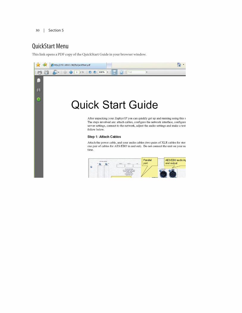
30 | Section 5
QuickStart MenuThis link opens a PDF copy of the QuickStart Guide in your browser window.

| 31
6 Making Connections with other units
Obviously, the main job of the Z/IP ONE is to make high quality audio connections with other units in remote locations, usually over the Internet. This section will help you to set up your Z/IP ONE, create useful lists of other units, and make reliable connections to them.
6.1CreatingaZ/IPIdentityontheZ/IPServerThe first step in connecting with other units is to create a Z/IP ONE Name for your unit on the Z/IP server:
1. From the front panel user interface, navigate to the Setup menu, and then to the Z/IP Server sub-menu.
2. In the “Device/Unit Name” field, enter a name for your unit that will help identify it to other users. Don’t worry if you enter a name that has been chosen by another user: the Z/IP server will generate a unique name by appending a number to the end of the name. If you don’t like this new auto-created name, simply enter another choice.
3. Enter the GROUP NAME and GROUP PASSWORD if you are not going to be part of the Public group on the Z/IP server.
4. Select the desired level of “visibility” for your device. The visibility option determines if your unit will be visible to others in the directory listing. There are three choices here. The first, “visible to all” is just what the name indicates; anyone will be able to see the name and the group of your Z/IP. The second, “group visible” allows only members of your group (those that know the group password) to see your Z/IP. The last option, “hidden” is just that; your Z/IP does not appear in any directory listings. Please note that this option only affects the directory listing. Anyone is still able to call you regardless of the choice you make here (just like you continue to get phone calls during dinner time even if you have an unlisted number).
5. Scroll down to the “Z/IP Server Name”. Check to make sure that a valid Z/IP Server Name has been entered in the Z/IP Server Hostname field. “zip.telos-systems.com” is the default server name, but you may have your own Z/IP Server configured elsewhere.
6. Click: “Activate Settings”

32 | Section 6
6.2ThePhonebookThe Z/IP ONE has a nifty way of managing your list of commonly used contacts: The Phonebook. Press the Auto key on the front panel. On the screen you will see a list of other units and (possibly) the online status of each unit.
Three symbols are used to indicate the status of the units in your list: a filled in bullet indicates the unit is online. An empty bullet indicates that the unit is not currently online. The “?” indicates that the buddy is an RTP or TSCP connection. Since these connections do not use the Z/IP Server, their online status cannot be reported. Lastly, if there is no symbol next to the name, the Z/IP server is currently unreachable or it does not know about the device (perhaps the other Z/IP ONE changed names or groups). If there is no circle at all, the Z/IP server either does not know this device or this is not a TSCP buddy.
When you are viewing the phonebook, turn the control knob to highlight the unit in the list that you would like to call. Press the knob or the AUTO button to call the unit selected.
Add a Buddy to Your ListManual Method
To add an entry manually, first click the “Phonebook” on the main screen then click the “Manual Add” button in the submenu. The Add dialog will be displayed.
Enter the device name, group name and group password. If the unit is a member of the “public” group you may leave the password blank. Leave the “Call Type” selection as TSCP.
Now, enter the “screen name” of the entry as you would like it to appear in the buddy list. If you leave this blank the device name will be used as the Buddy List entry name.
If you would like this Buddy to be connected to one of the Panic Dial pins on the Parallel Port on the back panel of your Z/IP ONE, assign it to one of the 8 inputs pins using the Panic Dial Input Bit field. NOTE: You must also enable this pin for Panic Dial functionality from the Settings/Parallel Port submenu.
Click the Save button to save the entry to the Buddy List. Press the AUTO key on the front panel to return to the AUTO menu. If you have entered a valid unit name in the DEVICE NAME field, you should now see the new entry and the status of the unit in your list. If the status appears as a question mark (but Z/IP server indicator is filled on the main status screen) then there is a problem with the device or group name entered. If the Buddy appears with no circle at all, the Z/IP server either does not know this device or this is not a TSCP buddy. Check the device and group names for possible misspellings. You may also try to find the device in the directory listing perhaps using a wildcard or Soundex search.

MAKinG ConneCTionS WiTH oTHer uniTS | 33
Directory Method
You can add a unit to you buddy list directly from the directory listing screen. From the main menu first click “Phonebook” then “Browse Z/IP Server”
On the right side of the screen, you will see a list of the various groups on the Z/IP Server. If you see the name of the group in which you would like to search, select it from the list to enter the Device Search screen. If not, enter the first few letters of the group name in the Optional Mask field and press OK. The list will now be populated only with those group names that begin with those letters.
When searching for groups or devices by name, entering the first few characters will return all names that begin with those characters. The directory also supports soundex searches which are useful when you’re not sure of the exact spelling of the name. Adding a % character to the end of a name tells the server to perform a Soundex search.
Select the appropriate group from the list to enter the Device Search screen.
If you know the password for the selected group then enter it in the Group password field. If you do not enter a password then only the devices that are publicly visible will be displayed.
Now enter a search pattern in the Device Search Pattern to limit your search, or leave it blank and press OK twice to see the first 100 or so devices in the group, listed alphabetically.
Select the device name from the list once you have located the appropriate name.
You can now add the device to your Buddy List by clicking the “Add …” button.
6.3CallingusingtheCallHistoryLogSelect the History button on the main menu to open the Z/IP ONE’s call log. Each call in the list is preceded by a symbol indicating an incoming or outgoing call. An arrow pointing to the right (towards the unit name) indicates an outgoing call. An arrow pointing to the left (away from the unit name) indicates an incoming call.
To place a call to a unit listed in the Call History, simply browse the list and select the unit by pressing the Control Knob. Then select the “Call” button on the screen to place the call.
You can also add a unit to your Buddy List from the Call History Log. Find the unit in the list, select it, and hit the “Save Selected” button on the screen (instead of “Call”). You will be taken directly to the Phonebook menu where you can enter a screen name and panic dial bit if desired.
6.4RelayConnectionovertheServerIn certain cases, when both ends are behind very restrictive NATs it may not be possible to establish a direct connection between the two units. In such cases, the Z/IP ONE Server provides a limited backup mode that will still allow you to make a connection. Unit A will send its compressed audio data to the Z/IP Server, which will, in turn, relay this data to Unit B. The same occurs in the opposite direction.

34 | Section 6
6.5SIPCallsThe Z/IP ONE fully supports the Session Initiation Protocol (SIP). SIP is a signaling protocol widely used for voice over IP (VoIP) applications. SIP is also specified as the connection method used by the EBU Audio Contribution over IP (ACIP) standard. Using SIP, the Z/IP ONE is able to accept and make calls to a variety of devices, including some VoIP phones. This section describes how to configure the Z/IP ONE for SIP and how to make and receive SIP
In order for a SIP call to be successful the two devices involved in the call must agree on a common codec. This is done though a codec negotiation step during the initial SIP call establishment. If no common codec can be selected then the call will fail. The Z/IP supports the following codecs for SIP calls: G.711, G.722, MPEG Layer 2, MPEG AAC (Zephyr Xstream compatible) and linear PCM.
SIP ConfigurationSIP can be used in two modes: direct or with a SIP server. Direct mode is just what you would expect, one device calls another directly. A SIP server entry is used when you have established VoIP service and all VoIP calls need to be routed through that provider. Another case when a SIP server may be used is when your facility has a VoIP PBX and the calls need to be routed though the PBX.
If you need to use a SIP server, enter the IP address of the SIP server, the name (or phone number) to regis-ter with the SIP server and the password (if required) into the appropriate fields of the Setup->Network->SIP Server submenu. Once you save the settings the Z/IP will register with the SIP server and all outgoing calls will be routed though the SIP server. Incoming calls are always accepted either directly or through the SIP server.
Making SIP CallsYou can make SIP calls by entering the address of the device to call or by adding a SIP speed dial entry. A SIP address has the following format: “sip:name@address”. Using the “sip:” prefix tells the Z/IP that this is going to be a SIP call. The “name” portion is either the name or phone number of the remote device and the “address” is the IP address of the device or of that device’s proxy server (if it has one).
Adding SIP Devices to the Buddy ListTo enter a SIP buddy make sure the type is set to SIP and the device name is set to the SIP name, or for direct SIP calls, “name@ip”.

| 35
7 The z/ip Server
In the Quick Start Guide section you were asked to enter settings for the Z/IP Server. This section describes the purpose of the server and the functions it provides.
A Z/IP Server is configured and maintained by Telos Systems as a service to our customers; it provides a set of services to enhance the functionality of your Z/IP: the directory service, the presence server, NAT traversal service, and media relay service. Organizations may host their own Z/IP server, if desired the following subsections describe each service in more detail.
7.1DirectoryServiceThe directory service allows your Z/IP ONE to register itself with a unique group and device name. The group and device name together form a persistent “phone number” for your Z/IP. Other users can always find and call your Z/IP regardless of what IP address you happen to be using that day. This is especially important when your ISP has given you a dynamic IP address or when you take the Z/IP on the road.
The directory service also allows you to locate other Z/IPs by browsing the server directory right from your Z/IP. Wildcard and Soundex searches allow you to find the device you’re interested in even if you don’t remember the exact spelling of the other device’s name or group.
Of course, you are in complete control over how your Z/IP ONE appears in the directory. You may list your Z/IP ONE as “visible to all”, “visible only to others in the same group” or even “hidden”. While in hidden mode, your Z/IP does not appear in the directory but it is still reachable by people that know your Z/IP’s name and group.
7.2PresenceServiceThe presence service allows you to see the state of the other Z/IPs in your “buddy” (or speed dial) list. This way you know if the other Z/IP is online, offline or busy before you even attempt the call.
The state information is updated a few times per minute to always keep the list up to date.
7.3NATTraversalServiceMany networks make use of network address translation (NAT) devices to get around the shortage of pub-lic IP addresses. In this case the router will have a “public IP address” (e.g. a “real” IP address accessible from the Internet) and device on the local LAN have “dummy IP addresses” (accessible on through the router’s IP address plus a port number), generally in the 192.168.x.y or 10.10.x.y subnets. NATs can be very useful, but they also make it difficult to reach devices that are behind the NAT (section 10.6, below, describes NATs in more detail). The Z/IP server allows your Z/IP device to detect when it is installed behind a NAT as well as to determine the type of NAT in use. This helps allow the units to reach each other, even when both sides are installed behind NATs.

36 | Section 7
7.4MediaRelayServiceNot all NATs behave the same way. Some NATs are very restrictive and go to great lengths to prevent data from outside the network to reach devices on the inside. This is a great security feature for PCs but not so good for devices that need to receive calls from the outside. The Z/IP together with the server’s NAT traversal service can automatically get through most types of NATs.
When both sides are behind very restrictive NATs it may not always be possible to get through the NAT in a manner that allows the two end devices to communicate directly. In these extreme cases the media relay service allows the two Z/IPs to communicate by having the server exchange the audio data.
Direct communication between Z/IPs is always preferred over using the media relay service. We offer the option as a “panic solution” should other methods fail to provide a connection. Units using a direct communication path have a lower end-to-end audio delay.
If you find yourself behind a very restrictive NAT but you have control over it (or can ask a network administrator) then it is best to configure port forwarding on the NAT (section 10.6 below describes how). This will allow your Z/IP to communicate directly with any other device without having to rely on the media relay service.

| 37
8 Groups and Directory Services
This chapter describes the ideas behind organizing your Z/IP ONEs by using “groups”. It also covers how your unit(s) will appear in the server directory.
During configuration a Z/IP ONE is assigned a Device/Unit name. This name is used to refer to this Z/IP ONE when connecting to other units; it becomes part of this unit’s address or “phone number”. The other part of the unit’s address is the group to which the unit belongs. Together the unit name and the group form a unique device address. A good analogy is that the phone number = the group and the name = the extension. Needless to say, you must have both pieces of information in order to place a “call”.
WhyGroups?Groups are useful because they allow you to keep your Z/IP ONEs logically grouped. They make it easier for others to find you and simplify the task of selecting a name for the device. A device name needs to be unique only within your group; it does not have to be unique among all other Z/IPs in the world. We’ve all been frustrated when trying to select a login name for services like Yahoo™ mail and finding that most obvious names have already been taken by others. Group passwords prevent others from becoming part of your group and from viewing the names of the Z/IPs within your group, except for the ones you allow.
ThePublicGroupEvery Z/IP ONE is initially configured to be a member of the “public” group. The “public” group is a special group that exits by default on the server. It is special because anyone has access to it (the group password is also “public”) and it is never deleted.
When you first connect to the server, your Z/IP ONE will join the public group. You may use any device name you like but if the name is already in use by another device the server will assign you a unique name. At this point you may keep this name, try to select another or better yet, create your own group.
CreatingGroupsGroups can be created at any time and you may create as many groups as you need. Groups are created by going to the “Z/IP Server” configuration dialog and selecting the “Create a Group” option. Companyname-city is one useful way to define groups within a large organization.
A dialog will prompt you for the desired group name, group password and group administrative password.
Click the “Create Group” button to create the group. A message will indicate if the operation succeeded or failed. If the group creation failed due to a duplicate name then you will need to change the name and try again. Using the name of your organization, or department, for the group name may be more likely to succeed.
A group uses two passwords. The first is the password that others will need in order to be able to join the group or to see devices that are listed as group private (more on this a bit later). The group administrative password is used to change the group passwords later if needed.
You should give your group password out only to people that you want to have as members of your group. For those outside your organization you should use the public group – that is why we created it. You should NEVER give out your group administrative password.

38 | Section 8
DirectoryListingVisibilityThe server directory allows users to find other Z/IPs without having to know their currently assigned IP address. But there are times when you may want to limit the visibility of your Z/IP ONE.
When you register with the server, your Z/IP ONE can select one the following visibility modes:
1. Visible to all: Anyone is able to see your Z/IP’s directory listing.
2. Visible to group: Only visible to those devices that know your group’s password. Of course, this option is not useful for the public group since anyone knows the public group’s password.
3. Hidden: Your Z/IP is not shown in the server directory. Others are still able to call you if they know your device’s name and group.
GroupandDeviceNameLongevityGroups remain active on the server as long as they have at least one Z/IP ONE that belongs to that group. If a group has no members, then the server will delete the group after 24 hours.
Z/IP names remain valid on the server for six months. After six months of inactivity the name is removed from the server directory. In most cases this is not a problem; even if the name was removed from the server when the Z/IP connects again the name entry will be created again.
There is a case (perhaps rare) that you should be aware of. If your Z/IP ONE is the only member of its group and it has been inactive for six months then the server will remove it from the directory. Twenty four hours later the group would be deleted as well since it is now empty. If the device is powered on at a later time, it would not be able to connect to the group (since the group is no longer there). Should this happen you will need to create the group again. Or just avoid this situation altogether by making sure that your Z/IP ONE gets online at least once every six months.
ReusingaZ/IPNameThe server does not allow two Z/IP devices to use the same Device/Unit name. A name is registered to a particular device, and the server does not allow other devices to accidentally take a name that is already in use. There are times however, when you do need to use the same name again. For example, you may replace a unit and want to use the same name on the new one. This section describes how you can assign an existing name to a new unit.
Please note that you may only take an existing name within your own group. You can never do this in the public group or in a group to which you don’t have the password.
If there is a time when you need to use the same Device/Unit name on another Z/IP ONE you simply configure the new Z/IP with the same name and group as the old device. Since no two devices can have the same name at the same time you should make sure there is no other device connected to the server that is currently using the selected name.
Once you connect to the server you will get a warning telling you that the name has been previously used by another device and are given a choice to select another name or to take over this name. If you choose to take over the name then the new device becomes associated with the name.
Please use this feature cautiously. Taking over the name of a unit that is currently online could cause the units to fight over the name potentially resulting in loss of service to both units.

| 39
9 When an iT Departmentis not available
There are times when an IT department is not on hand to guide through some of the networking ins and outs. This chapter covers some of the basics to get you started.
9.1IPAddresses,SubnetMasksandGatewaysThis section describes the terms used in IT environments. You probably already know these terms but we included them here for completeness. The terms covered are IP Addresses, subnet masks, gateways, DNS and DHCP. Network Address Translation (NAT) is covered in its own section below.
IP AddressesInternet Protocol (IP) addresses identify electronic devices that are part of an IP network. The protocol uses these addresses to properly route the data to the destination. Without Network Address Translation (see section 8.6 below), every device connected to a common network would require a unique address.
There are two versions of IP. The current version is called IPv4 and is what we refer to in this manual. IPv6 is a new standard that is not yet widely deployed.
IPv4 addresses consist of a 32-bit number. To make it easier for humans to describe, IP addresses are written in a form called dotted decimal notation. To come up with a dotted decimal representation the 32-bit number is broken down into four parts, each part 8 bits long. Each part is converted to a decimal number and written out with a dot in between.
For example, a device that has a 32-bit IP address of 3,232,235,841 is commonly written out as 192.168.1.65. The figure below shows how this conversion takes place.
I hope you agree that 192.168.1.65 is easier to remember and talk about than 3,232,235,841.
Subnet MasksLarger networks are often broken down into subnets. Subnets make the network easier to manage. Subnets are connected to each other by routers: devices that route the packets to the destination. The Internet Protocol differentiates between local addresses (addresses on the same subnet) and remote addresses (on different subnets). It uses the subnet mask to accomplish this task. Subnet masks might also be called netmasks or IP masks.

40 | Section 9
Before we get too deep into binary numbers, host and network address parts you should be aware that you can safely treat the subnet mask as just another parameter to set when you configure an IP address. No deep understanding is required to find out what the local subnet mask is and to configure it for your IP device. We should also mention that one of the most commonly used subnet mask is 255.255.255.0. Read on to find out why.
Network and Host IDsTo deal with subnets, IP treats the IP address as consisting of two separate IDs: a network ID and a host ID. The network ID identifies the subnet while the host ID identifies the actual device on the subnet. If two devices have addresses with the same network IDs then they are on the same subnet and are able to exchange data directly. If not then they are on different subnets. Any data exchange between them would have to go through a router.
The protocol needs to split the IP address into the network and host parts so that it knows where to send the data packets. It accomplishes this splitting by using the subnet mask.
A subnet mask is a 32-bit number and it is commonly written out in dotted decimal notation just like an IP address. If you write it out as a binary number you will notice that it consists of a string of ones followed by a string of zeros. The ones indicate (they “mask”) the network portion of the IP address while the zeros indicate the host portion.
An example might explain this better. Using the same IP address as above, 192.168.1.65 with a subnet mask of 255.255.255.0 we find out that the network ID is 192.168.1.0 while the host ID is 65. Here is how we did it:
Step 1: Convert the mask to binary and we get 11111111 11111111 11111111 00000000.
Step 2: Convert the IP Address to ones as well.
Step 3: For each 1 in the subnet mask, keep the corresponding IP address bit as is and for each 0 convert the corresponding bit to zero. We end up with:
11000000 10101000 00000001 00000000 (or 192.168.1.0)
This is the network ID part of the IP address.
Step 4: Now we invert the mask, for each 0 in the subnet mask, keep the corresponding IP address bit as is and for each 1 set the corresponding bit to zero. We get:
00000000 00000000 00000000 01000001 (or 65)
As you might know, computers love ones and zeros and built in binary operations make it a breeze to perform the network/host splitting. In a language like C or C++ the splitting would look like this:
network_id = ip_address & mask; host_id = ip_address & (~mask);

WHen An iT DepArTMenT iS noT AVAilABle | 41
IP Address ClassesFine, you say. That was mildly entertaining. But why muck about with subnet masks and binary operations? Why can’t they just always use the first 3 bytes for the network ID and the last byte for the host ID?
That is a fair question. The answer is that not every subnet is the same. Some corporate subnets are very large and have lots of hosts while some small subnets may have only a handful. The number of bits allocated to the host id determines the maximum number of IP devices you can have on the subnet. An 8-bit host id would allow for a subnet with a maximum of 255 hosts. That would not be enough in some cases.
The subnet mask solves this problem (although perhaps in an awkward way). On subnets with lots of hosts you can use fewer bits for the network ID and more bits for the host ID. On subnets with fewer hosts you can use more bits for the network ID and fewer bits for the host ID.
If you’re managing a private network, you’re free to select your subnet mask as you like. But on the Internet subnet masks are assigned by IP address class.
There are three common IP address classes: A, B and C. There is also a class D used for multicast addresses and a class E reserved for future use but here we’ll only look at the first three.
Class IP Address Range Subnet Mask
A 0.0.0.0 to 127.255.255.255
255.0.0.0
B 128.0.0.0 to 191.255.255.255
255.255.0.0
C 192.0.0.0 to 223.255.255.255
255.255.255.0
Class C is the most common IP address class so most of the subnet masks you see will likely be 255.255.255.0.
It is possible to have different subnet masks in addition to the ones above. The one thing to remember is that when converted to a binary number, subnet masks are always a continuous string of 1s followed by a string or 0s.
Windows Calculator can perform decimal, binary, hex and octal number conversions as well as some binary opera-tions but by default these capabilities are hidden. To reveals these functions, select “Scientific” mode from the View menu.
Most of the time you will not have to give subnet masks much thought. But there may be times when you are given an invalid subnet mask and this information may help you to detect it, saving you some aggravation.
GatewaysWe talked about networks having multiple subnets. Hosts on a subnet are able to communicate directly with each other. But what happens when a host needs to communicate to another that is on a different subnet? Simple: it uses the netmask to compare the network part of its address vs. the network part of the other device’s address. If they are different then it sends the packet to the gateway address.
The gateway is the router device that will take care of sending the packet on its way to the destination when the packet cannot be delivered on the local subnet. In a way, it is similar to dropping off a piece of mail at the local post office. They will take care of getting it to the destination for you.
Gateway addresses often end with .1 or .254. This is not a requirement; they could end with any number between 1 and 254. It is only a convenience because it leaves a continuous range of numbers that can be used by local hosts.

42 | Section 9
What about ending with .255 you ask? It is true that the largest possible value is 255 (or 11111111 in binary). But addresses that end with .255 have a special meaning in the Internet Protocol. They are local broadcast addresses. A packet sent to such a broadcast address will be delivered to all hosts on the local subnet.
DNSDNS stands for Domain Name System and in some ways it is similar to how the telephone book works: if you know the name, you can find the corresponding phone number to dial. DNS servers allow IP devices to find the IP address that corresponds to a given name (like telos-systems.com). The device can then use the IP address to talk to the host that has the name. Without a DNS server you would not be able to use address names; only dotted decimal IP addresses.
DHCP The Dynamic Host Configuration Protocol (DHCP) is a method to hand out IP addresses to IP devices on a network in a dynamic fashion. When an IP device that is configured to use DHCP is powered up (or connected to the network) it broadcasts a request for IP configuration information on the subnet. If a DHCP server is available, it will allocate an unused IP address (from a user specified range) and respond back to the device. The device can then configure itself with this IP address.
Using DHCP is a convenient method to configure an IP device but is not always the best course of action. When you use DHCP you don’t know the assigned IP address of the device plus this address may change from time to time. This is usually not a problem but in some cases it can be. If you need to configure the Z/IP via a web interface you will have to check the currently assigned IP address on the device via the front panel. Another situation where you do not want to use DHCP is if you wish to configure port forwarding on your NAT (see section 8.6below) since you must forward each desired port to a specific internal IP address.
9.2DiscovertheLocalNetworkSettingsYou need to plug in your Z/IP into a network but you don’t know the network settings. If there is no one to ask, what can you do?
Well, if there is a PC already plugged in into the same network then you can check the network configura-tion on the PC to determine the available network settings. The directions here are for a Windows PC.
1. Click the Start button on the task bar then select the Run option. The following dialog will appear:
2. Type “cmd” then click the OK button. This will open up a command prompt window.

WHen An iT DepArTMenT iS noT AVAilABle | 43
3. Type “ipconfig /all” then press Enter. You should see some entries similar to the ones shown below:
If the PC has multiple adapters you will see multiple entries displayed. In the example above, the PC has a wireless adapter and the Media State for it is shown as disconnected which indicates that the wireless is currently disabled.
Following this is an entry for the “Local Area Connection” Ethernet adapter. In our case this is the entry of interest because it is plugged in the same Ethernet network that we want to learn more about. The section of interest is under the heading “Ethernet Controller” and contains the following interesting entries:
Dhcp Enabled – Yes => Indicates that this PC was configured for DHCP so there must be a DHCP server available.
IP Address – 192.168.123.101 => IP address assigned by DHCP server.
Subnet mask – 255.255.255.0 => This is the netmask for this subnet. We can use the same netmask for the Z/IP.
Default Gateway – 192.168.123.254 => Another important entry, we can use the same gateway address on the Z/IP.
DNS Servers – 69.75.169.15 and .16 => DNS server addresses. Use the first one on the Z/IP.NOTE: The values in this example are not valid. Do not use these values on your Z/IP!
The ipconfig command will give you the subnet mask, gateway and DNS server addresses. It does not directly give you the IP address you should use on the Z/IP. If DHCP is available, as it is in this example, you can just configure the Z/IP to use DHCP. It will obtain an IP address automatically. If DHCP is not available then read on; the next section will describe this case.
9.3FindanAvailableIPAddresswithoutaDHCPServerWhat can you do if a DHCP server is not available on your network? In this case we’ll search for an IP address by pulling one out of a hat then testing to see if it is already in use.
In the example above, the PC’s IP address was 192.168.123.101 and the subnet mask was 255.255.255.0. This means that the last 8 bits indicate the host portion of the address. On this network, valid IP addresses would run from 192.168.123.1 to 192.168.123.254. Right away, we’ll avoid .1 and .254 because they are often assigned to the gateway. That leaves numbers from 2 to 253, still a pretty big range. So just choose a

44 | Section 9
number; I prefer to start with the lower numbers for no particular reason. For this example, I choose 10 so my first IP address to test will be 192.168.123.10.
1. Go to the Start menu on the task bar and select Run. Type “cmd” then click OK. A command prompt window should come up.
2. Type “ping “ followed by the trial IP address you selected (I’ll use 192.168.123.10 here) then press enter.
3. Well, we got a reply to our “ping”. This means that the IP address I selected is in use by another device so we can’t use it. Let’s try another. I will choose .15 this time:
4. Much better. The time out messages indicate that no device responded at this address. This is a pretty good indication that we can use this address. But let’s double check to be sure; there are some IP devices that may be configured to not reply to pings.
5. At the command prompt, type “arp –a”. Make sure to do this right after the unsuccessful ping command. This command displays the physical addresses associated with IP addresses that have been recently used.
6. The table shows one entry for the 192.168.123.10 address which we discovered in step 2 above. It does not show an entry for 192.168.123.15 which indicates that no device answered to this address. If there had been an IP device that does not answer pings, we still would expect to see its address in the arp table.
With this last test complete, we can be pretty confident that at this time, the 192.168.123.15 address is available. There is no guarantee that this address will remain valid forever. There may be a PC that uses this address that just wasn’t turned on at the moment. So keep an eye out for signs of duplicate IP addresses on the network. And notify your IT Department (or whomever is responsible for assigning IP addresses within the organization) ASAP that your are using this address. Read the following section for the gory details.

WHen An iT DepArTMenT iS noT AVAilABle | 45
9.4DuplicateIPAddressesDuplicate IP addresses can be difficult to diagnose. Some PCs may give you a warning at boot up that the currently configured IP address is in use. But other times, duplicate IP addresses are only discovered when an IP device behaves strangely.
For example, you know you assigned a particular IP address to your Z/IP but now you cannot open the web configuration page at that address. Or perhaps, sometimes it works but other times it does not.
The method to diagnose a duplicate IP address conflicting with your Z/IP is to learn the hardware address (also called the physical or MAC address) of your Z/IP and to use the “arp –a” command from a PC to watch the hardware address associated with your Z/IP’s IP address.
If you ever find a different hardware address associated with your Z/IP’s address then it is time to call your IT department. Or if an IT department is not available (since you’re reading this section anyway) just assign a different IP address to your Z/IP.
9.5UseTraceroutetoFindtheCommunicationBottlenecksThere are times when you’re exchanging data across the Internet and you notice that the transfer rate is really slowing down. One way to find out where the slow down is coming from is to perform a traceroute command. The Z/IP does this and shows you the information on the right side of the connection screen. But you can perform this bit of magic from any PC.
1. Click the Start button on the task bar and select Run. Type “cmd” and press Enter. This will open up our trusty command line window.
2. Type “tracert “ followed by the IP address or name of the host involved in the data exchange. I used www.google.com in this example:
3. The traceroute above shows the path of the data packets across the Internet. In this example the con-nection speed of every link was below 40 milliseconds except for hop #8, somewhere in San Jose (if we can trust the name). There it went up to about 200 milliseconds, indicating a bit of a bottleneck.
9.6NetworkAddressTranslation
What is it?Network Address Translation (NAT) is a technique that allows multiple IP devices on a private network to share a single public IP address. A NAT device has two network ports, one for the “private side” (the LAN) and the other for the “public side” (the Internet). As the name suggests, the NAT router translates the internal IP addresses to the public IP address.

46 | Section 9
In the example drawing above, the laptop sends a request to a search engine. The packet is labeled with the IP address of laptop, 192.168.1.100. The NAT router intercepts the packet and changes the packet to replace the laptop’s IP address with the public IP address assigned to the router, in this example 75.24.91.63 then sends the packet to the destination. The server responds to the IP address embedded in the packet so the packet is sent to the NAT router. The NAT remembers that the initial request came from the laptop so it forwards the packet to it. As far as the laptop is concerned, it does not know nor does it care that there is a NAT device in between.
Are all NAT devices the same?Not all NAT devices are the same as there is no defined standard on how a NAT should behave. Each vendor implements the NAT functions in a proprietary manner. You may hear NATs described as “full cone”, “re-stricted cone”, “port restricted cone” or “symmetric”. Not everyone agrees on the exact definition of these terms. A Wikipedia article (http://en.wikipedia.org/wiki/Network_address_translation) does a good job attempting to describe them. Perhaps counter-intuitively, symmetric NATs are among the most restrictive.
How do NAT devices affect communication devices?NAT has some benefits and drawbacks. It is a lower cost solution compared to obtaining multiple public addresses and it adds to security by hiding the internal structure of the network, and by allowing only pre-specified direct contact via port forwarding (see below). However, internal devices are no longer reachable from the outside because the NAT does not know which internal device the packet is destined for.
To get around this drawback, NATs have configuration capabilities which allow the user to forward specific ports to a given internal device or to add a single device DMZ (De-Militarized Zone) (where this device is now visible to the public).
How does the Z/IP Server help?Making NAT configuration changes can be cumbersome. The Z/IP uses the Z/IP Server to detect if it is installed behind a NAT and then determine the type of NAT as well. It is then able to accept calls from the outside without requiring you to make special configuration changes to your NAT. In addition to NAT tra-versal assistance, the Z/IP Server also allows you to see the status of your “buddy” devices, to get a directory listing of available devices or to dial another device by name.
How do I use port forwarding with the Z/IP?A common technique to help devices behind NATs to communicate is to use port forwarding. When you use port forwarding you tell the NAT that any time it receives data at a particular port that it should forward that data packet to a specific internal device.

WHen An iT DepArTMenT iS noT AVAilABle | 47
The Z/IP is able to communicate through most types of NATs without requiring any special configuration of the NAT. But some NATs are much more restrictive than others. Establishing a connection becomes even more difficult when both ends are behind very restrictive NATs. Port forwarding can help in these cases. If at least one of the sides uses port forwarding then a direct connection can be established much faster.
You can use port forwarding with the Z/IP in two steps:
1. On your Z/IP in the Z/IP Server Configuration page enter a value for the listen port. The default value is zero which tells the Z/IP to select a port on its own. You can choose any value from 1024 to 65,535 but please make a note of it. Also make a note of the IP address you assigned to the Z/IP (this is one of those cases when you should not use DHCP).
2. On your NAT’s configuration page, specify that the port you selected in step 1 above should be forwarded to the Z/IP’s address.
If you have more than one Z/IP behind a NAT and you use port forwarding you need to make sure that each Z/IP uses a different port. Some NATs may get very confused otherwise.


| 49
10 The parallel portand Contact Closure
As stated in the Installation section, the Z/IP has a DB25 connector on the back panel that provides contact closures (close-to-ground) inputs and outputs. There are 8 open-collector outputs, and 8 open collector inputs, each configurable from the Settings menu in the user interface. The DB25 connector is pinned out as follows:
PIN FUNCTION
1 +5 Volts DC 400 mA max
2 Output 0
3 Output 1
4 Output 2
5 Output 3
6 Output 4
7 Output 5
8 Output 6
9 Output 7
10 No Connection
11 No Connection
12 No Connection
13 No Connection
14 Input 0
15 Input 1
16 Input 2
17 Input 3
18 Input 4
19 Input 5
20 Input 6
21 Input 7
22 Not Connected
23 Not Connected
24 Not Connected
25 Ground
DB25 Male Connector

50 | Section 10
Parallel Outputs 0-7Outputs are open collector to ground and can sink up to 125 mA of current each (actually, any output can sink up to 400 mA, however the maximum combined current should be kept below 1000 mA). These can be used to convey logic from the far end codec, or they can be used for monitoring the status of the local unit. This functionality can be selected by a menu selection for each output in Settings menu. An equivalent schematic for the outputs is shown below.
If you wish to interface directly to 5 volt logic inputs, the outputs include a pull up resistor to 5 volts. If you need a logic high greater than 5 volts you may supply an external pull up resistor (2.2 kOhm to 10 kOhm is appropriate) to the voltage level require by your external logic inputs. You cannot use a voltage level less than 5V, however, you may use up to 50V.
If used with a relay or LED, then tie your external power source ground to pin 25 (or use the 5 VDC power supplied on pin 1) and run this power source through your device, with a resistor in series to limit maxi-mum current to less than 125 mA.
Equivalent schematic for the Parallel Outputs.
An external pull up resistor may be used if a logic high of greater than 5 volts is required. Alternatively, a voltage source (such as the 5 volts on pin 1) can be driven through an external device (such as a relay or LED) into the input.
Parallel Inputs 0-7All inputs are specially treated to accept either a voltage (up to 24 VDC), or a closure to ground, which may be provided by switches, relays, or logic outputs. The inputs are active low. In other words, shorting the input to ground causes it to become true (i.e. “asserted”).
An internal pull-up resistor to provide a TTL logic “High” (e.g. 2.2 kOhm to 5V).
Parallel logic input circuit

THe pArAllel porT AnD ConTACT CloSure | 51
The inputs can be transmitted to the far end Z/IP when using the AAC-HELD, or to a Zephyr Xstream in AAC mode. The inputs can also be used for local control functionality such as triggering auto dialing to your speed dial members.
10.1ParallelPortOutputModesThe 8 Parallel Contact Closure Outputs (“bits” 0 through 7) can each be set to one of six operating modes:
1. Off: The open-collector output is left floating, and will remain so.
2. On: The open-collector output is closed to ground, and will remain so.
3. End-to-End: The Output will reflect the state of the corresponding INPUT pin at the far-end of the call, provided that a coding mode supporting contact closures is used (AAC or HELD-AAC).
4. Connected: The contact closure will remain OFF until a call is connected, at which time it will close-to-ground. This function effectively mirrors the CONNECT light on the front panel GUI.
5. Receive Lock: The contact closure will remain OFF until a call is connected and the correct codec type has been determined and it has detected valid data. This indication is a pretty good indicator that audio should be present, and if it is not, that silence is being transmitted from the far end.
6. Follow Input: This is a diagnostic mode for locally testing the connections to the inputs and outputs. When this mode is used a given output bit becomes true whenever the corresponding input has been triggered and will remain so until the input is no longer asserted.
10.2ParallelPortInputModesThe 8 Parallel Contact Closure Inputs (“bits” 0 through 7) can each be set to one of six operating modes:
1. No Function: The input is not used, and any activity on this pin is ignored.
2. End-to-End: The state of this input pin will be sent to the far end codec where, if the appropriate OUTPUT pin is also set to “END-TO-END”, the status will appear. This function will only work in AAC and HELD-AAC coding modes.
3. Disconnect: If this input is closed-to-ground, the Z/IP will immediately disconnect any connected calls.
4. Panic Dial: If this pin is closed-to-ground, the Z/IP will immediately dial the buddy list member that has been configured for this pin. See Chapter 8 for more information on Buddy Lists, and how to configure them for Panic Dials.
5. Transmit 0: This will send data to the corresponding bit of the far end codec indicating the given input bit is unasserted. This can be used for troubleshooting, or can be used as simple identifier to distinguish different codecs at the far end.
6. Transmit 1: This will send data to the corresponding bit of the far end codec indicating the given input bit is asserted. This can be used for troubleshooting, or can be used as simple identifier to distinguish different codecs at the far end.


| 53
11 Audio Coding reference
11.1IntroductiontoAudioCodingTechnology
IntroductionAudio takes up a lot of data. Just a regular phone call uses 64,000 bits per second.
Without data reduction, CD-quality quality audio — 16 bits at 44.1kHz sample rate — requires a transmis-sion capacity of about 706 thousand bits per second (kbps) for each audio channel. But, the wires we use for remote broadcasting are on a telephone system designed for voice-grade communications: 8 bits at 8kHz sample rate, or 64 thousand bits per second (kbps) per channel. That’s 11% of what we need.
CURIOSITY NOTE!
You can arrive at these same numbers with nothing more complicated than grade-school math. Just multiply the sample rate by the sample depth: 44,100 samples per second * 16 bits per sample = 705,600 bits per second for CD-quality mono audio. Multiply by 2 for stereo.
You can reduce the data requirements by lowering the quality somewhat. 13 bits would yield a respectable 78 dB dynamic range, certainly adequate for casual home listening. And a 32kHz sample rate — with careful equipment design — will give you flat response to 15kHz, the practical limit for analog FM broadcasting in North America. Unfortunately, that still leaves us with telephone data channels about 93% too small to do the job. Besides, 13 bits is an awkward bit depth (resolution) for computers to deal with, and the audio it produces isn’t clean enough to survive today’s transmitter processors.
CURIOSITY NOTE!
Bit depth and sample rate translate easily into audio specifications. Digital audio must have a sample rate of at least twice the desired bandwidth, so 15kHz audio requires (after a safety margin) 32kHz sampling. Each bit of sample depth represents slightly more than 6dB of dynamic range.
The first practical coding methods used a principle called ADPCM, Adaptive Delta Pulse Code Modulation. This takes advantage of the fact that it takes fewer bits to code the difference, or delta, between successive audio samples compared to using the individual values. Further efficiency is had by adaptively varying the difference comparator according to the nature of the program material. G.722 and APT-X are examples of ADPCM schemes. They achieve around a factor of 4:1 reduction in bitrate.
G.722 achieves additional efficiency by allocating its bits to match the patterns in the human voice, and it’s considered adequate for news and talk programming over ISDN. But, for high-fidelity transmission, algorithms with more power are required. These are based on psychoacoustics, where the coding process

54 | Section 11
is adapted to the way we hear sounds. There are several algorithms available, with varying complexity and performance levels.
Some years ago, the international standards group ISO/IEC established the ISO/MPEG (Moving Pictures Expert Group), to develop a universal standard for encoding moving pictures and sound for digital storage and transmission media. The standard was finalized in November 1992 with three related algorithms, called Layers, defined to take advantage of psychoacoustic effects when coding audio. Layer 1 and 2 are intended for compression factors of about 4:1 and 6 or 8:1 respectively, and these algorithms have become popular in satellite and hard-disk systems. Layer-3 achieves compression up to 12.5:1 — 8% of the original size — making it ideal for ISDN.
Basic Principles of Perceptual CodingWith perceptual coding, only information that can be perceived by the human auditory system is retained.
Lossless – which, for audio, translates to noiseless – coding with perfect reconstruction would be an optimum system, since no information would be lost or altered. It might seem that lossless, redundancy-reducing methods (such as PKZIP, Stuffit, Stacker, and others used for computer hard-disk compression) would be applicable to audio. Unfortunately, no constant compression rate is possible due to signal-dependent variations in redundancy: There are highly redundant signals like constant sine tones (where the only information necessary is the frequency, phase, amplitude, and duration of the tone), while other signals, such as those which approach broadband noise, may be completely unpredictable and contain no re-dundancy at all. Furthermore, looking for redundancy can take time: while a popular song might have three choruses with identical audio data that would need to be coded only once, you’d have to store and analyze the entire song in order to find them. Any system intended for a real-time use over telephone channels must have a consistent output rate and be able to accommodate the worst case, so effective audio compression is impossible with redundancy reduction alone.
Fortunately, psychoacoustics permits a clever solution! Effects called “masking” have been discovered in the human auditory system. These masking effects (which merely prove that our brain is also doing something similar to bit rate reduction) have been found to occur in both the frequency and time domains and can be exploited for audio data reduction.
Most important for audio coding are the effects in the frequency domain. Research into perception has revealed that a tone or narrow-band noise at a certain frequency inhibits the audibility of other signals that fall below a threshold curve centered on a masking signal.
The figure below shows two thresholds of audibility curves. The lower one is the typical frequency sensi-tivity of the human ear when presented with a single swept tone. When a single, constant tone is added, the threshold of audibility changes, as shown in the upper curve. The ear’s sensitivity to signals near the constant tone is greatly reduced. Tones that were previously audible become “masked” in the presence of “masking tones,” in this case, the one at 300 Hz.
All signals below the upper “threshold of audibility” curve, or Masking Threshold are not audible, so we can drop them out or quantize them crudely with the least number of bits. Any noise which results from crude quantization will not be audible if it occurs below the threshold of masking. The masking depends upon the frequency, the level, and the spectral distribution of both the masker and the masked sounds.

AuDio CoDinG referenCe | 55
Masking effects in the frequency domain. A masking signal inhibits audibility of signals adjacent in frequency and below the threshold.
To benefit from the masking effects, perceptual coders use a filter bank to divide the input audio into mul-tiple bands for analysis and processing. The maximum masked noise level is calculated depending upon the spectral content, and the available bits are allocated so as to keep the quantization noise below the masking threshold at every point in the spectrum.
While coding efficiency increases with more bands and better frequency resolution, the time domain resolution decreases simultaneously owing to an inevitable side-effect of the band filtering process: higher frequency resolution requires a longer time window – which limits the time resolution. Happily, masking works also in the time domain. A short time before and a longer time after a tone is switched on and off, other signals below a threshold amplitude level are not noticeable. Filter banks with higher frequency resolution naturally exploit the ear’s time-masking properties.
Masking effects in the time domain. Masking occurs both before and after the masking signal.

56 | Section 11
The combined results of time and frequency vs. masking. Signals under the curve are inaudible.
IMPORTANT!
Due to a perceptual coder’s reliance on precisely modeling principles of human perception, audio to be coded should not be processed with any non-linear dynamics-processing such as clipping, multi-band compression, or hard limiting. Wideband compression, or AGC, is acceptable, and may be desirable if a consistent level cannot otherwise be achieved.
The same is true of audio that has been decoded, after passing through a perceptual coding cycle, but to much lesser degree.
For more information on this follow the link to our Omnia Audio website that has a paper delivered at the AES by Frank Foti on this topic. http://www.omniaaudio.com/techinfo/default.htm
The steps involved in the perceptual coding process are shown below:

AuDio CoDinG referenCe | 57
The components work as follows:
♦ The analysis filter bank divides the audio into spectral components. Sufficient frequency resolution must be used in order to exceed the width of the ear’s critical bands, which is 100 Hz below 500 Hz and 20% of the center frequency at higher frequencies.
♦ The estimation of masked threshold section is where the human ear/brain system is modeled. This determines the masking curve, under which noise must fall.
♦ The audio is reduced to a lower bit rate in the quantization and coding section. One the one hand, the quantization must be sufficiently coarse in order not to exceed the target bit rate. On the other hand, the error must be shaped to be under the limits set by the masking curve.
♦ The quantized values are joined in the bit stream multiplex, along with any side information.
Doing audio coding effectively means managing several tradeoffs. Most important is the number of samples coded together in one frame. Long frames have high delay, but are more efficient because the header and side information is transmitted less frequently. Longer frames offer the possibility to use filter banks with better frequency resolution. A fundamental principle in signal processing is that spectral splitting filters may have either good time resolution, or good frequency resolution, but not both. This makes sense when you consider that a longer time window means that the analyzer has more complete information, more full audio cycles, to work with .
In the case of rapidly changing input signals (transients) long frames are poorer than short ones because the time spread will lead to so called pre-echoes. For such signals, the size of the frame should correspond to the temporal resolution of the human ear. This can be achieved by using short frames or by changing the frame length according to the immediate characteristics of the signal.
MPEG By far, the most popular high fidelity audio coders rely upon techniques developed under the MPEG um-brella. MPEG stands for Motion Pictures Expert Group, a Joint Committee of the International Standards Organization (ISO) and the International Electrotechnical Commission. Over a decade ago, when the CD had just been introduced, the first proposals for audio coding were greeted with suspicion and disbelief. There was widespread agreement that it would simply not be possible to satisfy golden ears while deleting 80% or more of the digital audio data. But the audio coding pioneers were persistent and the MPEG audio group was formed. Since 1988, they have been working on the standardization of high quality audio coding. Today, almost all agree not only that audio bit rate reduction is effective and useful, but that the MPEG process has been successful at picking the best technology and encouraging compatibility across a wide variety of equipment.
The MPEG process is open and competitive. A committee of industry representatives and researchers meet to determine goals for target bit rate, quality levels, application areas, testing procedures, etc. Interested organizations that have something to contribute are invited to submit their best work. A careful double blind listening test series is then conducted to determine which of the entrant’s technologies delivers the highest performance. The subjective listening evaluations are done at various volunteer organizations around the world that have access to both experienced and inexperienced test subjects. Broadcasters are the most common participants with many of the important test series conducted at the BBC in England, the CBC in Canada, and NHK in Japan. Finally, results are tabulated, a report is drafted and ultimately a standard is issued.
In 1992, under MPEG1 (the first of the MPEG standards), this process resulted in the selection of three related audio coding methods, each targeted to different bit rates and applications. These are the famous layers: 1, 2 and 3. As the layer number goes up, so does performance and implementation complexity. Layer 1 is not much used. Layer-2 is widely used for DAB in Europe, audio for video, and broadcast playout systems. Layer-3 – which Telos was the first to use in the Zephyr – is widely used in broadcast codecs and

58 | Section 11
has gone on to significant Internet and consumer electronics fame under the moniker derived from the file extension: MP3. MPEG2 opened the door for new work, and some minor improvements were added to both Layers 2 and 3. In 1997, the first in the AAC family was added to the MPEG2 standard. MPEG4 is ongo-ing now, but it has already been decided that AAC will be the “general audio” coder under this umbrella. (MPEG3 was skipped for reasons unknown.)
MPEG4 AAC (Advanced Audio Coding)The MPEG4 AAC system is the newest audio coding method selected by MPEG. It is a fully state-of-the-art audio compression tool that provides performance superior to any known approach at bit rates greater than 64 kbps and excellent performance relative to the alternatives at bit rates reaching as low as 16 kbps.
The idea that led to AAC was not only to start fresh, but also to combine the best work from the world’s leading audio coding laboratories: Fraunhofer, Dolby, Sony, and AT&T were the primary collaborators that offered components for AAC. The hoped for result was ITU (International Tele-communications Union) “indistinguishable quality” at 64 kbps per mono channel. That is, quality indistinguishable from the original, with no audio test item falling below the “perceptible, but not annoying” threshold in controlled listening tests.
The MPEG test items include the most difficult audio known to codec researchers, so this was daunting challenge. The thinking was that if a codec could pass this test, it would surely be transparent for normal program material like voice and pop music, which are much more easy to encode. AAC designers chose to use a new modular approach for the project, with components being plugged-in to a general framework in order to match specific application requirements and the always-present performance/complexity/delay tradeoffs.
Compared to the previous layers, AAC takes advantage of such new tools as temporal noise shaping, back-ward adaptive linear prediction and enhanced joint stereo coding techniques. AAC supports a wide range of sampling rates (8–96 kHz), bit rates (16–576 kbps) and from one to 48 audio channels.
AAC is a lot more sophisticated than the previous MPEG layers 2 &3, providing significantly more cod-ing power. Because it uses a modular approach, new ideas can be developed and plugged in to the basic structure. This had the additional advantage that it was possible to combine the various components from different developers, taking the best pieces from each. AAC was built on a similar structure to Layer-3, and thus retains most of its features. Nevertheless, compared to the previous MPEG layers, AAC benefits from some important new additions to the coding toolkit:.
♦ An improved filter bank with a frequency resolution of 2048 spectral components, nearly four times the number used by Layer-3.
♦ Temporal Noise Shaping, a new and powerful element that minimizes the effect of temporal spread. This benefits voice signals, in particular.
♦ A Prediction module guides the quantizer to very effective coding when there is a noticeable signal pattern, like high tonality.
♦ Perceptual Noise Shaping allows a finer control of quantization resolution, so bits can be used more efficiently.
Because it uses this modular approach, an implementer may pick and choose among the component tools to make a product with appropriate performance/complexity ratios. Or, new modules can be developed later and “plugged in” to its basic structure. Three default profiles have been defined, using different combina-tions of the available tools:
♦ Main Profile. Uses all tools except the gain control module. Provides the highest quality for applica-tions where the amount of random accessory memory (RAM) needed is not constrained.

AuDio CoDinG referenCe | 59
♦ Low-complexity Profile. Deletes the prediction tool and reduces the temporal noise-shaping tool in complexity.
♦ Sample-rate Scalable (SRS) Profile. Adds the gain control tool to the low complexity profile. Allows the least complex decoder.
The block diagram of the AAC encoder is shown below. It is considerably more sophisticated than the previ-ous MPEG Layer-2 and Layer-3 systems, and therefore offers more coding power.
Because AAC was built on a similar structure to Layer-3, it therefore retains some of its powerful features:
♦ Redundancy Reduction. A Huffman encoding process causes values that appear more frequently to be coded with shorter words, while values that appear only rarely are coded with longer words. This results in an overall increase in coding efficiency – with no degradation, since it is a completely lossless process.
♦ Bit Reservoir buffering. Often, there are some critical parts in a piece of music that cannot be en-coded at a given data rate without audible noise. These sequences require a higher data rate to avoid artifacts. On the other hand, some signals are easy to code. If a frame is easy, then the unused bits are put into a reservoir buffer. When a frame comes along that needs more than the average amount of bits, the reservoir is tapped for extra capacity.

60 | Section 11
♦ Ancillary Data. The bit reservoir buffer offers an effective solution for the inclusion of such ancillary data as text or control signaling. The data is held in a separate buffer and gated onto the output bit stream using some of the bits allocated for the reservoir buffer when they are not required for audio.
♦ The Joint Stereo mode takes advantage of the redundancy in stereo program material. The encoder switches from discrete L/ R to a matrixed L+R/ L-R mode dynamically, depending upon the program material.
The result of all this is that the researchers succeeded: AAC provides performance superior to any known codec at bitrates greater than 64kbps, and excellent performance relative to the alternatives at bitrates reaching as low as 16 kbps.
And the researchers succeeded in achieving the ITU goal: AAC is the first codec system to fulfill the ITU requirements for indistinguishable quality at 128 kbps/stereo . It has approximately 100% more coding power than Layer-2 and 30% more power than the former MPEG performance leader, Layer-3. For more information on AAC, and the tests of it, see our web site for a paper on the subject: www.zephyr.com.
It offers:
♦ 20 kHz mono or stereo audio bandwidth.
♦ Significantly less delay than Layers 2 or 3.
♦ Full-fidelity mono on a single 56kbps channel.
♦ Affordable, transparent, audio transmission for AM/FM radio or television audio.
AAC-LD (AAC Low Delay)When announcers use codecs for broadcast remote applications, they often need to have natural two-way interaction with other program participants located back at the studio, or callers. Because it is a hot topic for engineers working in the field of Internet telephony, a number of studies have been conducted to determine user’s reactions to delays in telephone conversations. The data apply directly to the application of profes-sional codecs to remotes, so it is interesting to take a peak over the shoulder of the telecom guys to see what they have learned.
For broadcast remotes, we try to arrange our system so that there is no path for the field announcer’s voice to return to his/her headphones. Nevertheless, sometimes echo is unavoidable. For example, this can hap-pen when a telephone hybrid has leakage or when a studio announcer has open-air headphones turned-up loud and the audio makes its way into the studio microphone.
When there is no echo, it has been discovered that anything less than 100 ms one-way delay permits normal interaction between participants. Between 100 and 250 ms is considered “acceptable.” ITU-T standard G.114 recommends 150 ms as the maximum for “good” interactivity. Echo introduces a different case. As you might expect, echo is more or less annoying depending upon both the length of time it is delayed and its level. Telephone researchers have measured and quantified reactions, and ITU-T G.131 reports the findings and makes recommendations.

AuDio CoDinG referenCe | 61
Summary of ITU-T G.13, with recommendations for designers of telephone systems that must cope with echo. This shows Talker Echo Loudness Rating vs. delay.
There are codecs using other than perceptual technologies that have lower delay, but they are not as powerful. That is, for a given bitrate, they do not achieve fidelity as good as the MPEG systems we have been examining. The common G.722 is an example. It uses ADPCM (Adaptive Delta Pulse Code Modulation), which can have delay as low as 10 ms, but with much poorer quality. So the question arises: Is it possible to have high quality and low delay in the same codec? Until recently, the answer was no. But new develop-ments in codecs have changed the picture. One of the main objectives in audio coding is to provide the best tradeoff between quality and bit rate. In general, this goal can only be achieved at the cost of a certain coding delay. Codecs for voice telephone applications have use ADPCM and CELP because they have much lower delay than perceptual codecs. These are optimized for voice and can have reasonably good performance.
Zephyr users have known for years that Layer-3 offers all the fidelity needed for most broadcast situations. However, they also know that the delay of Layer-3 can be frustrating, particularly if high fidelity is needed in both directions and parties at the two ends must carry on a conversation.
The folks at Fraunhofer were aware of these factors, and have developed an extension to AAC called “AAC Low Delay,” or “AAC-LD” for short. ACC-LD offers quality equivalent to Layer-3 with less than 25% of the delay!
AAC-LD combines the advantages of perceptual coders (such as Layer-3) with certain principles of speech coders. Compared to speech coders, AAC-LD handles both speech and music with good quality. Unlike speech coders, however, audio quality scales up with bit rate, and transparent quality can be achieved. AAC-LD’s coding power is roughly the same as Layer 3, meaning that mono high fidelity 15 kHz audio may be sent via one ISDN channel. With ISDN’s two channels, you achieve near CD quality stereo.
Delay in perceptual codecs is dependent on several parameters:
♦ Frame length. Time is required to collect all the samples for a frame. The longer the frame, the more the delay.
♦ Filter bank delay. This causes an additional delay equivalent in time to the frame delay.

62 | Section 11
♦ Look-ahead delay for block switching. Layer-3 and AAC use filter banks with high frequency resolution. For signals with high tonality, efficiency is high. But when there are transients, a dynamic switching process changes to a filter bank with lower frequency resolution and better time resolu-tion. In order to correctly decide when to make this change, a look ahead process is required, adding delay.
♦ Bit reservoir. The length of this buffer determines how much delay this process contributes.
The overall delay is a combination of all of these components, divided by the sampling rate. The delay scales linearly and inversely with the sampling frequency.
How AAC-LD Gets its Low DelayAAC-LD is based on the core AAC work, so much is similar, but each of the contributors to the delay had to be addressed and modified:
♦ The frame length is reduced to 512 or 480 samples, with the same number of spectral components at the filter bank output.
♦ No dynamic block switching is used because the required look-ahead delay is too big. The temporal problem that causes pre-echoes is handled by the Temporal Noise Shaping module.
♦ The “window shape” of the spectral filter is enhanced to be adaptive. Normally, the shape is a simple sine curve, but AAC-LD can use a shape that has a lower overlap between the bands. This signifi-cantly improves performance with transients, without adding any delay.
MPEG-4 High Efficiency AAC (HE-AAC, previously known as “aacPlus™”)HE-AAC is an extension of AAC with the addition of Spectral Band Replication, a technique (developed by Coding Technologies) of synthesizing high frequency audio content based on the lower frequency data and side-chain information. SBR dramatically increases the efficiency of coding when using low bitrates. HE-AAC v1 is AAC plus SBR, while HE-AAC v2 adds Parametric Stereo to further increase the efficiency of coding stereo signals. For more on the SBR technology see the papers on the Telos web site about “aacPlus” which was the name of this codec before acceptance by MPEG.
MPEG-4 Enhanced Low Delay AACHigh audio quality, low coding delay and very low data rates: AAC Enhanced Low Delay (AAC-ELD) is the perfect choice for any delay critical application that demands full audio bandwidth at data rates down to 24 kbit/s.
AAC-ELD combines the strengths of its two main components, MPEG-4 AAC Low Delay, and Spectral Band Replication (SBR). Whereas MPEG-4 AAC-LD features low encoding/decoding latency, SBR provides high quality audio at very low bit rates. SBR is also used in MPEG-4 HE-AAC, one of today’s most efficient audio codecs.
AAC-ELD became an MPEG standard in January 2008.
ISO/MPEG LAYER-2MPEG Layer-2 was an extremely popular early perceptual coding method, primarily because it’s easier and less expensive to implement — particularly at the encoder — and practical devices using it were available earlier than Layer-3. It’s a preferred choice for applications where very large data capacity is available, such as satellite links, high-capacity Primary ISDN or T1 circuits, and hard disk storage systems using Ethernet for signal distribution.

AuDio CoDinG referenCe | 63
We include it in Z/IP to offer compatibility with the widest variety of codecs, and for use at high bit rates.
Layer-2 J-Stereo
The Layer-2 joint stereo mode uses an “intensity coding” method. This method has high coding power and is quite effective, but hurts stereo separation on some program material. Audio above 3 kHz or so is combined to mono and panned to one of seven positions across the stereo stage.
G.722This technology pre-dates perceptual coding. It is much simpler than the transform methods, but suffers from poorer audio performance. It has the benefit of low cost and the unique advantage of low delay. It has been around as an international standard the longest, and is probably the most widely used system. In our view, this technology is acceptable for mono voice where high fidelity is not necessary. It is good also for cueing and intercom channels.
We have included G.722 in Z/IP because:
♦ It had been the most popular coding method early on, so there are many of these codecs in use. Because it is a standard, codecs from various manufacturers have a good probability of being able to interwork with one-another. (We’ve tested with many units and have found no problems so far.)
♦ G.722 has the lowest delay of all popular coding methods.
This method was invented in the late 70s and adopted as a standard in 1984 by the CCITT, the Consultative Committee for International Telephony and Telegraphy (renamed as ITU-T in 1993). The technique used is Sub-Band ADPCM (Adaptive Delta Pulse Code Modulation), which achieves data reduction by transmit-ting only the difference between successive samples. G.722 does this in two audio frequency sub-bands: 50 Hz to 4 kHz and 4 to 7 kHz.
DEEP TECH NOTE!
Only two bits are allocated per sample for audio frequencies above 4 kHz – sufficient for conveying the sibilance in voice signals, but not very good for intricate musical sounds. Also, the “predictor model” used to determine the step size in the adaptive function is designed only for speech. This is why music transmitted via G.722 has a distinct ‘fuzzy’ quality.
G.722 has a frequency response extending to 7.5 kHz with fairly poor fidelity. Unless there is no alternative, it should not be used for music.


| 65
12 Mobile network Devices
12.1HowtoconfigureMobileDataDevicesontheZ/IP/ONEThe Z/IP ONE supports a variety of Mobile Network Devices (see section 13.2 through 13.3) through the USB port on the back of the unit. To use one of these devices is not complicated:
1. Boot the Z/IP ONE WITHOUT the USB device plugged in (this is important because the Z/IP may not recognize the device unless it is plugged in while the unit is up and running).
2. Once the unit has completed the boot process and is showing the main menu screen, plug one of the approved mobile devices into either of the USB ports on the back of the Z/IP (see the Telos web site for the most-up-to-date list of approved devices).
3. Navigate to the Setup->Network menu and continue as follows for the type of network to be used:
For WiFi/WLAN Networks
1. Press to access the main menu. Using the Control Knob navigate to: SETUP ->NET-
WORK -> WiFi/WLAN option. Press to select.
2. Rotate the Control knob to highlight the relevant fields and press to select them. Use the keypad to enter the necessary information for the Encryption Method, the ESSID Network Name and the Password String. Note that you must enter the ESSID and password exactly as they are set up in the router, as these names are typically case sensitive. Once entered scroll down and click on Activate Settings.
3. Press repeatedly till you return to the main menu. Navigate to: SETUP menu. Rotate the
Control knob to highlight Streaming Option and press change it to WiFi/WLAN. Press
to accept.
4. Press till you return to the main menu and navigate back to the STATUS screen. If you connect properly through the WiFi stick to the router the Z/IP indicator should fill in indicating it has found the Z/IP Server.
5. Try connecting to the Telos test line or another Z/IP unit.

66 | Section 12
For UMTS/EVDO Wireless Networks1. From the Setup->Network menu choose the UMTS/EVDO option;
2. Set the country, protocol, dial number,PIN number, account name, account password,and provider URL (all these things should have been given to you from your wireless provider).
3. Select Activate Settings to commit your settings to memory and begin using them.
4. ESC back to Setup Menu and choose Streaming Interface and choose WiFi/WLAN or UMTS/EVDO as appropriate; choose WiFi/WLAN if you are using a Wi-Fi USB stick or UMTS/EVDO for wireless cellular service:
5. You will now be connecting over the USB device when making a call.
12.2EVDODevicesSupportedCurrently the Z/IP supports the following EVDO devices:
1. Sierra Wireless USB device AC595U for either Sprint or Verizon
2. Novatel Ovation U727
3. Novatel Ovation U720
Please contact customer support or the Telos Systems website for an updated list of supported devices.
Also, note that your EVDO device must be activated, using a computer, with the software that comes with it. Please follow any directions that came with the device and contact your service provider for assistance if necessary. Once you have verified it is operating as intended, follow the steps above.

| 67
13 using the field upgrade option
13.1SoftwareMenuThe Z/IP ONE has two memory “banks” each of which can hold a complete firmware load. This permits updating the firmware without risk, since the current software is never erased until the user has already run the revised version. By going to the Setup->Software- you can view the version in each bank and configure which bank will be used at the next restart. Choosing Reboot to Primary will cause the unit disconnect any audio connections and reboot the unit using the version indicated for Primary. Choosing Reboot to Secondary will do likewise using that version.
The restore defaults will not affect the version to be booted, but will return all user settings including the IP Addresses to their original factory default. Use this option with caution because it will erase your network settings as well as everything else and you no longer be able to control the unit remotely using its prior IP address.
13.2UpdatingtheSoftwarethroughtheWebInterfaceAlthough this will rarely be necessary, the Z/IP provides the ability to upgrade the internal software in the field. This option is only available through the HTML configuration web page. Access this page using a browser, over the LAN connection. Type http://123.456.789.10 <enter> where 123.456.789.10 is the IP address for the Z/IP One’s LAN port.
You will be prompted for a user name and password. The user name is ‘user’ and the password is “Telos” (note the capital “T”). You will now see the Z/IP’s status screen. Next, click on Software Management near the top of the screen. You will see the following:

68 | Section 13
The Z/IP ONE has two methods of software update, depending on the extent of the changes made in the software version. The Unit consists of two pieces of software embedded in the units flash memory: the application Firmware, and the Kernel. In some case you will only need to update the current Firmware. In others, you may need to update the Kernel and the Firmware together: this is called a System Update.
Firmware UpdateFrom the Setup->Software menu, examine the contents of the firmware in Bank 0 (“primary”) and Bank 1 (“secondary”) of the flash memory. Make sure that you are “running” out of the Opposite bank from the one which you will be updating. In other words, when you upload the update to the non-running bank, it will erase the current contents of that bank, so make sure that you preserve the correct firmware version in the other bank. If you are NOT running from the bank that you would like to preserve, then check the radio button next to that bank and the click the “Reboot” button on the web page. When the unit comes back up, navigate back to this page, and continue with the update process.
You are now ready to begin the update:
1. Download the latest software version for the Z/IP ONE from the Telos Systems web page (www.telos-systems.com). Save it to a convenient place on your PC. Partition updates are typically named following the naming convention “zipone-04Apr2011-V1.0.0r-full.tgz”. DO NOT unpack this archive.
2. Connect to the embedded web page of the Z/IP ONE you will be upgrading by typing its IP Address into the Navigation Bar of your browser.
3. Navigate to the “Update” page of the Z/IP ONE.
4. Locate the “Update Firmware” section of the page and click the “Browse” button to locate the software package you just downloaded. Navigate through your computer’s directories and double

uSinG THe fielD upGrADe opTion | 69
click the file that you downloaded.
5. Now click on the “Update Firmware” button.
6. You should now refresh the page and see the new software version shown in the opposite bank from which you had been running. Click the radio button next to the new bank, and reboot the system.
WARNING
DO NOT TURN OFF THE UNIT OR DISCONNECT THE NETWORK CABLE DURING THE UPDATE PROCESS. INTERRUPTING THE PROGRAMMING OF THE Z/IP’S FLASH MODULE CAN CORRUPT THE DATA AND RENDER THE UNIT UNUSABLE.
13.3InstallingaNewFlashCardIn certain circumstances it may be necessary to replace the internal flash card containing the Z/IP ONE software. This card is located inside the unit.
WARNING
PLEASE FOLLOW ALL INSTRUCTIONS CLOSELY. ENSURE THAT YOU ARE PROPERLY GROUNDED AND HAVE TAKEN ESD PRECAUTIONS BEFORE YOU INSTALL ANY CARD INSIDE THE Z/IP. THE Z/IP CONTAINS SENSI-TIVE ELECTRONIC DEVICES THAT CAN BE DAMAGED BY IMPROPER HANDLING. CONTACT TELOS SYSTEMS CUSTOMER SUPPORT WITH ANY QUESTIONS REGARDING THESE PROCEDURES.
1. Power down the unit and unplug the AC power cord before opening the chassis.
2. Remove the 10 top cover screws of the unit and store them in a safe place. Remove the unit’s top cover.
3. Locate the SD card and slot on the motherboard of the Z/IP.
4. Push the SD Card until you hear a click, then release. This will eject the SD card.
5. Carefully slide the card out of the slot.
6. Insert the new SD card into the slot and firmly press it until it clicks.
7. Place the top cover of the Z/IP back into its proper position. Reinstall the 10 screws.
8. Attach the AC power cord and power on the unit.


| 71
14 z/ip/one AuDio SpeCifiCATionS:
Line Input: : +4dBu input
THD+N Pro/Pro: < 0.03% @ +12dBu, 1 kHz Sine;
Freq Response: +/- 1dB 25– 20 kHz
Head Room: 18dB
Dynamic Range: > 87dB Unweighted> 90 dB “A” Weighted
Crosstalk: Over 80 db
Output Clipping: + 22dBu
Output Impedance: 50 Ohm differential
Input Impedance: 6K Ohm differential
Analog to Digital Converter: 24bits
Digital to Analog Converter: 24bits
Power: 115Vac 14.2 Watts


| 73
15 Warranty and Application Cautions
Z/IP ONE LIMITED WARRANTY
This Warranty covers “the Products,” which are defined as the various audio equipment, parts, software and accessories manufactured, sold and/or distributed by TLS Corp., d/b/a Telos Systems (hereinafter “Telos Systems”).
With the exception of software-only items, the Products are warranted to be free from defects in material and workmanship for a period of two years from the date of receipt by the end-user. Software-only items are warranted to be free from defects in material and workmanship for a period of 90 days from the date of receipt by the end-user.
This warranty is void if the Product is subject to Acts of God, including (without limitation) lightning; improper installation or misuse, including (without limitation) the failure to use telephone and power line surge protection devices; accident; neglect or damage.
EXCEPT FOR THE ABOVE-STATED WARRANTY, TELOS SYSTEMS MAKES NO WARRANTIES, EXPRESS OR IMPLIED (INCLUDING IMPLIED WARRANTIES OF MERCHANTABILITY AND FIT-NESS FOR A PARTICULAR PURPOSE).
In no event will Telos Systems, its employees, agents or authorized dealers be liable for incidental or conse-quential damages, or for loss, damage, or expense directly or indirectly arising from the use of any Product or the inability to use any Product either separately or in combination with other equipment or materials, or from any other cause.
In order to invoke this Warranty, notice of a warranty claim must be received by Telos Systems within the above-stated warranty period and warranty coverage must be authorized by Telos Systems. If Telos Systems authorizes the performance of warranty service, the defective Product must be delivered, shipping prepaid, to: Telos Systems, 1241 Superior Avenue East, Cleveland, Ohio 44114.
Telos Systems at its option will either repair or replace the Product and such action shall be the full extent of Telos Systems’ obligation under this Warranty. After the Product is repaired or replaced, Telos Systems will return it to the party that sent the Product and Telos Systems will pay for the cost of shipping.
Telos Systems’ authorized dealers are not authorized to assume for Telos Systems any additional obligations or liabilities in connection with the dealers’ sale of the Products.


| 75
16 Safety notification
This symbol, wherever it appears, alerts you to the presenceof uninsulated, dangerous voltage inside the enclosure –voltage which may be sufficient to constitute a risk of shock.
This symbol, wherever it appears, alerts you to importantoperating and maintenance instructions. Read the manual.
1. Read All Instructions. All safety and instructions must be read before operating the product.
2. Retain All Instructions. All safety and operating instructions must be maintained for future refer-ence.
3. Heed All Warnings. All warnings on the product and those listed in the operating instructions must be adhered to.
4. Follow All Instructions. All operating and product usage instructions must be followed.
5. Heat. This product must be situated away from any heat sources such as radiators, heat registers, stoves, or other products (including power amplifiers) that produce heat.
6. Water and Moisture. Do not use this product near water.
7. Attachments. Do not use any attachments not recommended by the product manufacturer as they may cause hazards.
8. Power Sources. This product must be operated from the type of power source indicated on the marking label and the installation instructions. If you are not sure of the type of power supplied to your facility, consult your local power company.
9. Grounding and Polarization. This product is equipped with a polarized AC plug with integral safety ground pin. Do not defeat the safety ground in any manner.
10. Power Cord Protection. Power supply cords must be routed so that they are not likely to be walked on or pinched by items placed upon or against them. Pay particular attention to the cords at AC wall plugs and convenience receptacles, and at the point where the cord plugs into the product.
11. Lightning. For added protection during a lightning storm, or when the unit is left unattended or unused for long periods of time, unplug the unit from the AC wall outlet. This will prevent damage to the product due to lightning and power surges.
12. Overloading. Do not overload AC wall outlets, extension cords, or integral convenience outlets as this can result in a fire or electric shock hazard.
13. Object and Liquid Entry. Never push objects of any kind into this product through openings as they may touch dangerous voltage points or short out parts that could result in a fire or electric shock. Never spill liquid of any kind on the product.

76 | Section 17
14. Accessories. Do not place this product on an unstable cart, stand, tripod, bracket or table. Any mounting of the product needs to follow the manufacturer’s instructions.
15. Servicing. Refer all servicing to qualified service personnel.
16. Damage Requiring Service. Unplug this product from the wall AC outlet and refer servicing to quali-fied service personnel under the following conditions:
♦ When the AC cord or plug is damaged.
♦ If liquid has been spilled or objects have fallen into the product.
♦ If the product does not operate normally (following operating instructions).
♦ If the product has been exposed to rain or water.
♦ If the product has been dropped or damaged in any way.
♦ When the product exhibits a distinct change in performance (outside of normally operating specifications).
17. Replacement Parts. When replacement parts are required, be sure the service technician has used replacement parts specified by the manufacturer. Unauthorized substitutions may result in fire, electric shock, or other hazards.
18. Safety Check. Upon completing of any repairs to this product, ask the service technician to perform safety checks to determine that the product is in proper operating condition.
19. Cleaning. Do not use liquid cleaners or aerosol cleaners. Use only a damp cloth for cleaning the exterior of the product only.