temperature difference controller tdc 1 - nn-energy.se · the temperature difference controller tdc...
TRANSCRIPT

1
Temperature Difference Controller TDC 1
Installation and operating instructions
Read carefully before installation, commissioning and operation
2
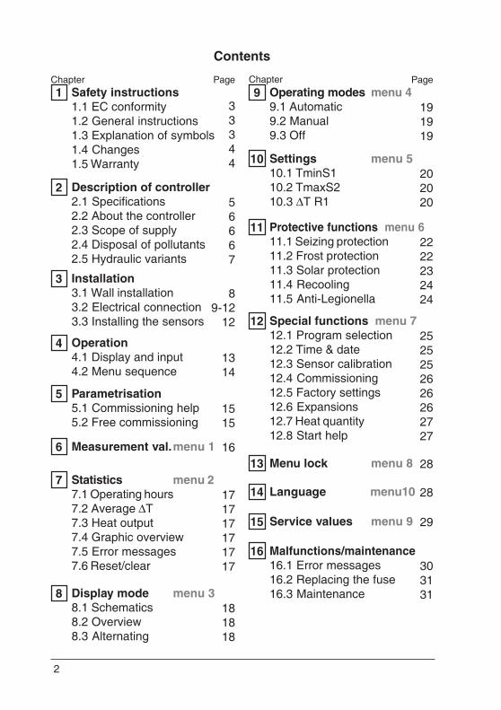
Contents
Safety instructions1.1 EC conformity1.2 General instructions1.3 Explanation of symbols1.4 Changes1.5 Warranty
133344
Description of controller2.1 Specifications2.2 About the controller2.3 Scope of supply2.4 Disposal of pollutants2.5 Hydraulic variants
256667
Operation4.1 Display and input4.2 Menu sequence
41314
Parametrisation5.1 Commissioning help5.2 Free commissioning
51515
Operating modes menu 49.1 Automatic9.2 Manual9.3 Off
9191919
Measurement val.menu 16 16
Statistics menu 27.1 Operating hours7.2 Average ΔT7.3 Heat output7.4 Graphic overview7.5 Error messages7.6 Reset/clear
7171717171717
Display mode menu 38.1 Schematics8.2 Overview8.3 Alternating
8181818
Settings menu 510.1 TminS110.2 TmaxS210.3 ΔT R1
10202020
Menu lock menu 813 28
Service values menu 915 29
Malfunctions/maintenance16.1 Error messages16.2 Replacing the fuse16.3 Maintenance
16303131
N
Installation3.1 Wall installation3.2 Electrical connection3.3 Installing the sensors
38
9-1212
Protective functions menu 611.1 Seizing protection11.2 Frost protection11.3 Solar protection11.4 Recooling11.5 Anti-Legionella
112222232424
Special functions menu 712.1 Program selection12.2 Time & date12.3 Sensor calibration12.4 Commissioning12.5 Factory settings12.6 Expansions12.7 Heat quantity12.8 Start help
122525252626262727
Language menu1014 28
Chapter Page Chapter Page
3
Danger
Danger
Caution
Caution
Safety instructions1 1
1.1 EC declaration of conformityBy affixing the CE mark to the unit the manufacturer declares that the TDC 1conforms to the following relevant safety regulations:- EC low voltage directive
73/23/EEC, as amended by 93/68/EEC- EC electromagnetic compatibility directive
89/336/EEC version 92/31/EEC version 93/68/EECConformity has been verified and the corresponding documentation andthe EC declaration of conformity are kept on file by the manufacturer.
1.2 General instructions It is essential that you read this!These installation and operating instructions contain basic instructions andimportant information regarding safety, installation, commissioning, maintenanceand the optimal use of the unit. Therefore these instructions must be readcompletely and understood by the installation technician/specialist and by thesystem user before installation, commissioning and operation of the unit.The valid accident prevention regulations, VDE regulations, the regulations ofthe local power utility, the applicable DIN-EN standards and the installationand operating instruction of the additional system components must alsobe observed. The controller does not under any circumstances replace anysafety devices to be provided by the customer!Installation, electrical connection, commissioning and maintenance of the unitmay only be carried out by specialists who possess the appropriate training.For the user: Make sure that the specialist gives you detailed information onthe function and operation of the controller. Always keep these instructions inthe vicinity of the controller.
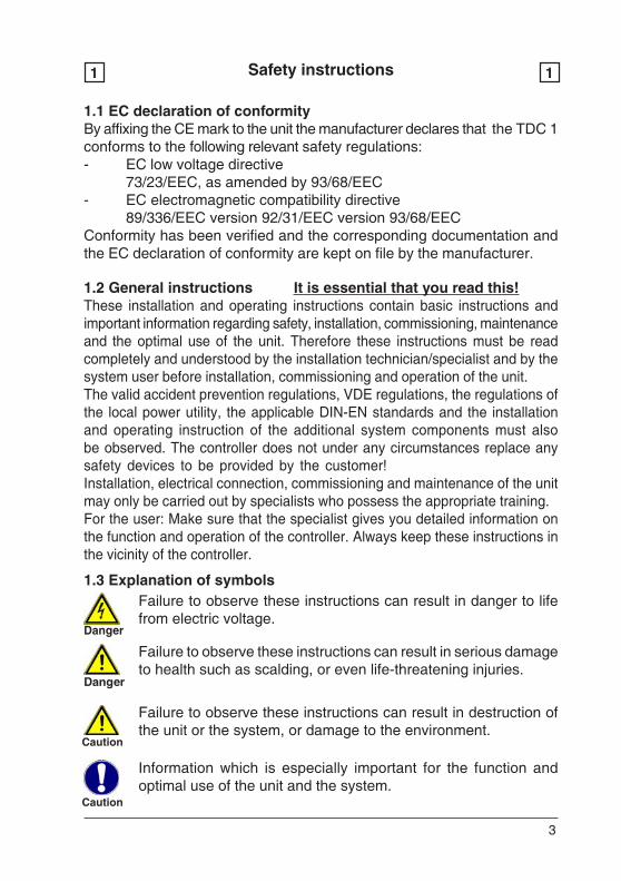
1.3 Explanation of symbolsFailure to observe these instructions can result in danger to lifefrom electric voltage.
Failure to observe these instructions can result in serious damageto health such as scalding, or even life-threatening injuries.
Failure to observe these instructions can result in destruction ofthe unit or the system, or damage to the environment.
Information which is especially important for the function andoptimal use of the unit and the system.

4
Safety instructions1 1
Danger
1.4 Changes to the unit
1.5 Warranty and liabilityThe controller has been manufactured and tested with regard to high qualityand safety requirements. The unit is subject to the statutory guarantee periodof two years from the date of sale.The warranty and liability shall not include, however, any injury to persons ormaterial damage that is attributable to one or more of the following causes:- Failure to observe these installation and operating instructions- Improper installation, commissioning, maintenance and operation- Improperly executed repairs- Unauthorised structural changes to the unit- Installation of additional components that have not been tested
together with the unit- Any damage resulting from continued use of the unit despite an
obvious defect- Failure to use original spare parts and accessories- Use of the device for other than its intended purpose- Operation above or below the limit values listed in the
specifications- Force majeure
- Changes, additions to or conversion of the unit are not permittedwithout the written permission from the manufacturer
- It is likewise forbidden to install additional components that have notbeen tested together with the unit
- If it becomes clear that safe operation of the unit is no longer possible,for example because of damage to the housing, then turn the controlleroff immediately
- Any parts of the unit or accessories that are not in perfect conditionmust be exchanged immediately
- Use only original spare parts and accessories from the manufacturer.- Markings made on the unit at the factory must not be altered,
removed or made illegible- Only the settings actually described in these instructions may be made
on the controller
Changes to the unit can compromise the safety and function of theunit or the entire system.nit or the entire system.
5
Description of controller2 2
2.1 Specifications
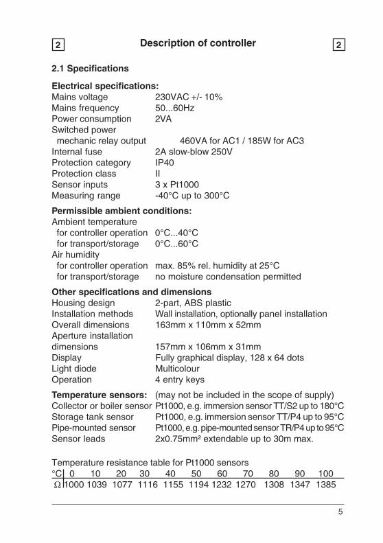
Electrical specifications:Mains voltage 230VAC +/- 10%Mains frequency 50...60HzPower consumption 2VASwitched power mechanic relay output 460VA for AC1 / 185W for AC3Internal fuse 2A slow-blow 250VProtection category IP40Protection class IISensor inputs 3 x Pt1000Measuring range -40°C up to 300°C
Permissible ambient conditions:Ambient temperature for controller operation 0°C...40°C for transport/storage 0°C...60°CAir humidity for controller operation max. 85% rel. humidity at 25°C for transport/storage no moisture condensation permitted
Other specifications and dimensionsHousing design 2-part, ABS plasticInstallation methods Wall installation, optionally panel installationOverall dimensions 163mm x 110mm x 52mmAperture installationdimensions 157mm x 106mm x 31mmDisplay Fully graphical display, 128 x 64 dotsLight diode MulticolourOperation 4 entry keys
Temperature sensors: (may not be included in the scope of supply)Collector or boiler sensor Pt1000, e.g. immersion sensor TT/S2 up to 180°CStorage tank sensor Pt1000, e.g. immersion sensor TT/P4 up to 95°CPipe-mounted sensor Pt1000, e.g. pipe-mounted sensor TR/P4 up to 95°CSensor leads 2x0.75mm² extendable up to 30m max.
Temperature resistance table for Pt1000 sensors°C 0 10 20 30 40 50 60 70 80 90 100 Ω 1000 1039 1077 1116 1155 1194 1232 1270 1308 1347 1385
6
Description of controller2 2
2.3 Scope of supply- Temperature Difference Controller TDC 1- 3 screws 3,5x35mm and 3 plugs 6mm for wall installation- 6 strain relief clips with 12 screws, replacement fuse 2A slow-blow- Installation and operating instructions TDC 1Optionally contained depending on design/order:- 2-3 PT1000 temperature sensors and immersion sleevesAdditionally available:- Pt1000 temperature sensor, immersion sleeves, overvoltage protection,- Various additional functions by means of supplementary circuit boards
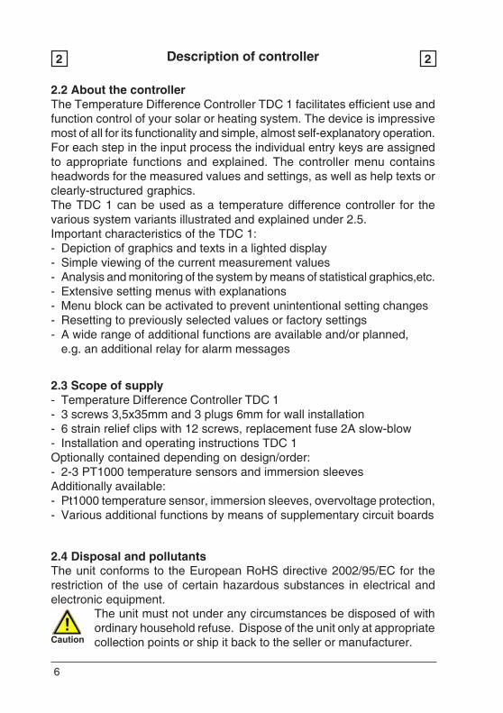
2.4 Disposal and pollutantsThe unit conforms to the European RoHS directive 2002/95/EC for therestriction of the use of certain hazardous substances in electrical andelectronic equipment.
Caution
The unit must not under any circumstances be disposed of withordinary household refuse. Dispose of the unit only at appropriatecollection points or ship it back to the seller or manufacturer.
2.2 About the controllerThe Temperature Difference Controller TDC 1 facilitates efficient use andfunction control of your solar or heating system. The device is impressivemost of all for its functionality and simple, almost self-explanatory operation.For each step in the input process the individual entry keys are assignedto appropriate functions and explained. The controller menu containsheadwords for the measured values and settings, as well as help texts orclearly-structured graphics.The TDC 1 can be used as a temperature difference controller for thevarious system variants illustrated and explained under 2.5.Important characteristics of the TDC 1:- Depiction of graphics and texts in a lighted display- Simple viewing of the current measurement values- Analysis and monitoring of the system by means of statistical graphics,etc.- Extensive setting menus with explanations- Menu block can be activated to prevent unintentional setting changes- Resetting to previously selected values or factory settings- A wide range of additional functions are available and/or planned,
e.g. an additional relay for alarm messages
7
Description of controller2 2
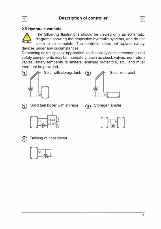
2.5 Hydraulic variantsThe following illustrations should be viewed only as schematicdiagrams showing the respective hydraulic systems, and do notclaim to be complete. The controller does not replace safety
devices under any circumstances.Depending on the specific application, additional system components andsafety components may be mandatory, such as check valves, non-returnvalves, safety temperature limiters, scalding protectors, etc., and musttherefore be provided.
11
Caution
1
3 4
5
2Solar with storage tank Solar with pool
Solid fuel boiler with storage Storage transfer
Raising of heat circuit
8
Installation3 3
Caution
A
Fig.3.1.1
Fig.3.1.2
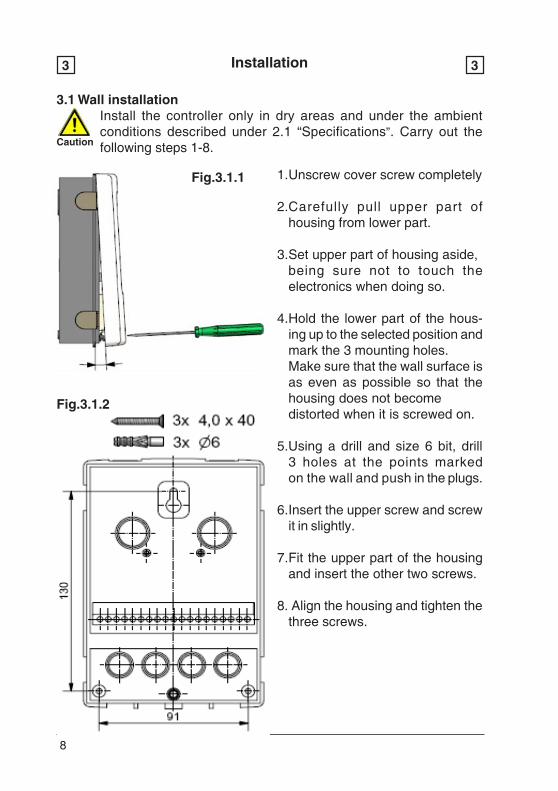
3.1 Wall installationInstall the controller only in dry areas and under the ambientconditions described under 2.1 “Specifications”. Carry out thefollowing steps 1-8.
1.Unscrew cover screw completely
2.Carefully pull upper part ofhousing from lower part.
3.Set upper part of housing aside,being sure not to touch theelectronics when doing so.
4.Hold the lower part of the hous-ing up to the selected position andmark the 3 mounting holes.Make sure that the wall surface isas even as possible so that thehousing does not becomedistorted when it is screwed on.
5.Using a drill and size 6 bit, drill3 holes at the points markedon the wall and push in the plugs.
6.Insert the upper screw and screwit in slightly.
7.Fit the upper part of the housingand insert the other two screws.
8. Align the housing and tighten thethree screws.
9
Installation3 3
Caution
Danger
Caution
Caution
Fig.3.2.1
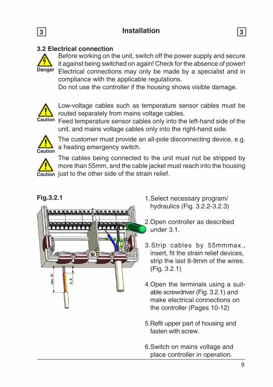
3.2 Electrical connectionBefore working on the unit, switch off the power supply and secureit against being switched on again! Check for the absence of power!Electrical connections may only be made by a specialist and incompliance with the applicable regulations.Do not use the controller if the housing shows visible damage.
Low-voltage cables such as temperature sensor cables must berouted separately from mains voltage cables.Feed temperature sensor cables only into the left-hand side of theunit, and mains voltage cables only into the right-hand side.
The customer must provide an all-pole disconnecting device, e.g.a heating emergency switch.
The cables being connected to the unit must not be stripped bymore than 55mm, and the cable jacket must reach into the housingjust to the other side of the strain relief.
1.Select necessary program/hydraulics (Fig. 3.2.2-3.2.3)
2.Open controller as describedunder 3.1.
3.Strip cables by 55mmmax.,insert, fit the strain relief devices,strip the last 8-9mm of the wires.(Fig. 3.2.1)
4.Open the terminals using a suit-able screwdriver (Fig. 3.2.1) andmake electrical connections onthe controller (Pages 10-12)
5.Refit upper part of housing andfasten with screw.
6.Switch on mains voltage andplace controller in operation.
10
DangerCaution
Installation3 3
3.2 Electrical connection (connection)
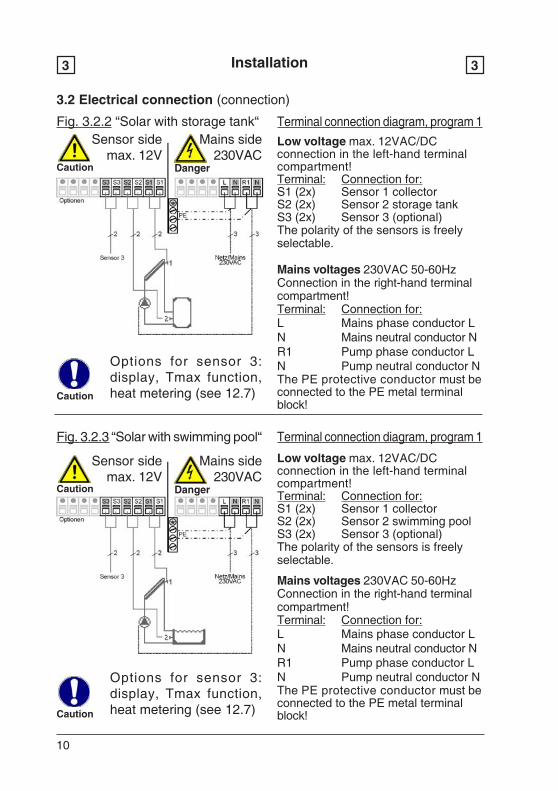
Fig. 3.2.2 “Solar with storage tank“ Terminal connection diagram, program 1
Terminal connection diagram, program 1Fig. 3.2.3 “Solar with swimming pool“
Low voltage max. 12VAC/DCconnection in the left-hand terminalcompartment!Terminal: Connection for:S1 (2x) Sensor 1 collectorS2 (2x) Sensor 2 swimming poolS3 (2x) Sensor 3 (optional)The polarity of the sensors is freelyselectable.
Mains voltages 230VAC 50-60HzConnection in the right-hand terminalcompartment!Terminal: Connection for:L Mains phase conductor LN Mains neutral conductor NR1 Pump phase conductor LN Pump neutral conductor NThe PE protective conductor must beconnected to the PE metal terminalblock!Caution
Low voltage max. 12VAC/DCconnection in the left-hand terminalcompartment!Terminal: Connection for:S1 (2x) Sensor 1 collectorS2 (2x) Sensor 2 storage tankS3 (2x) Sensor 3 (optional)The polarity of the sensors is freelyselectable.
Mains voltages 230VAC 50-60HzConnection in the right-hand terminalcompartment!Terminal: Connection for:L Mains phase conductor LN Mains neutral conductor NR1 Pump phase conductor LN Pump neutral conductor NThe PE protective conductor must beconnected to the PE metal terminalblock!
Sensor sidemax. 12V
Mains side230VAC
Sensor sidemax. 12V
DangerCaution
Mains side230VAC
Caution
Options for sensor 3:display, Tmax function,heat metering (see 12.7)
Options for sensor 3:display, Tmax function,heat metering (see 12.7)
11
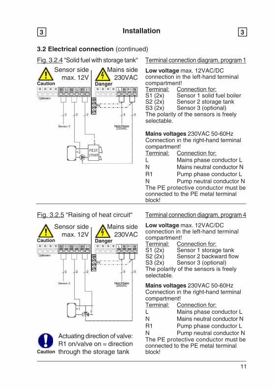
Terminal connection diagram, program 1Fig. 3.2.4 “Solid fuel with storage tank“
Low voltage max. 12VAC/DCconnection in the left-hand terminalcompartment!Terminal: Connection for:S1 (2x) Sensor 1 solid fuel boilerS2 (2x) Sensor 2 storage tankS3 (2x) Sensor 3 (optional)The polarity of the sensors is freelyselectable.
Mains voltages 230VAC 50-60HzConnection in the right-hand terminalcompartment!Terminal: Connection for:L Mains phase conductor LN Mains neutral conductor NR1 Pump phase conductor LN Pump neutral conductor NThe PE protective conductor must beconnected to the PE metal terminalblock!
Installation3 3
3.2 Electrical connection (continued)
Terminal connection diagram, program 4Fig. 3.2.5 “Raising of heat circuit“
Low voltage max. 12VAC/DCconnection in the left-hand terminalcompartment!Terminal: Connection for:S1 (2x) Sensor 1 storage tankS2 (2x) Sensor 2 backward flowS3 (2x) Sensor 3 (optional)The polarity of the sensors is freelyselectable.
Mains voltages 230VAC 50-60HzConnection in the right-hand terminalcompartment!Terminal: Connection for:L Mains phase conductor LN Mains neutral conductor NR1 Pump phase conductor LN Pump neutral conductor NThe PE protective conductor must beconnected to the PE metal terminalblock!Caution
Actuating direction of valve:R1 on/valve on = directionthrough the storage tank
Sensor sidemax. 12V
DangerCaution
Mains side230VAC
Sensor sidemax. 12V
DangerCaution
Mains side230VAC

12
Terminal connection diagram, program 5Fig. 3.2.6 “Storage transfer“
Low voltage max. 12VAC/DCconnection in the left-hand terminalcompartment!Terminal: Connection for:S1 (2x) Sensor 1 storage 1S2 (2x) Sensor 2 storage 2S3 (2x) Sensor 3 (optional)
The polarity of the sensors is freelyselectable.
Mains voltages 230VAC 50-60HzConnection in the right-hand terminalcompartment!Terminal: Connection for:L Mains phase conductor LN Mains neutral conductor NR1 Pump phase conductor LN Pump neutral conductor N
The PE protective conductor must beconnected to the PE metal terminalblock!
Installation3 3
3.2 Electrical connection (continued)
Caution
The heat is transferredfrom storage 1 tostorage 2
Caution
Caution
Sensor sidemax. 12V
DangerCaution
Mains side230VAC
3.3 Installing the temperature sensors
The temperature sensor cables must be routed separately frommains voltage cables, and must not, for example, be routed in thesame cable duct!
The controller operates with Pt1000 temperature sensors which areaccurate to the degree, thus ensuring optimal control of systemfunctions.
If desired the sensor cables can be extended to a maximum of30m using a cable with a cross-section of at least 0.75mm². Makesure that there is no contact resistance!Position the sensor precisely in the area to be measured!Only use immersion, pipe-mounted or flat-mounted sensor suitablefor the specific area of application with the appropriate permissibletemperature range.
13
Operation4 4
4.1 Display and Input
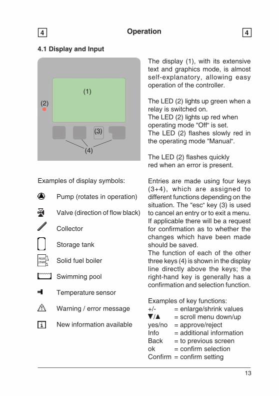
The display (1), with its extensivetext and graphics mode, is almostself-explanatory, allowing easyoperation of the controller.
The LED (2) lights up green when arelay is switched on.The LED (2) lights up red whenoperating mode “Off” is set.The LED (2) flashes slowly red inthe operating mode “Manual”.
The LED (2) flashes quicklyred when an error is present.
Entries are made using four keys(3+4), which are assigned todifferent functions depending on thesituation. The “esc” key (3) is usedto cancel an entry or to exit a menu.If applicable there will be a requestfor confirmation as to whether thechanges which have been madeshould be saved.The function of each of the otherthree keys (4) is shown in the displayline directly above the keys; theright-hand key is generally has aconfirmation and selection function.
Examples of key functions:+/- = enlarge/shrink values / = scroll menu down/upyes/no = approve/rejectInfo = additional informationBack = to previous screenok = confirm selectionConfirm = confirm setting
Examples of display symbols:
Pump (rotates in operation)
Valve (direction of flow black)
Collector
Storage tank
Solid fuel boiler
Swimming pool
Temperature sensor
Warning / error message
New information available
(1)
(2)
(3)
(4)
14
Operation4 4
4.2 Menu sequence and menu structure
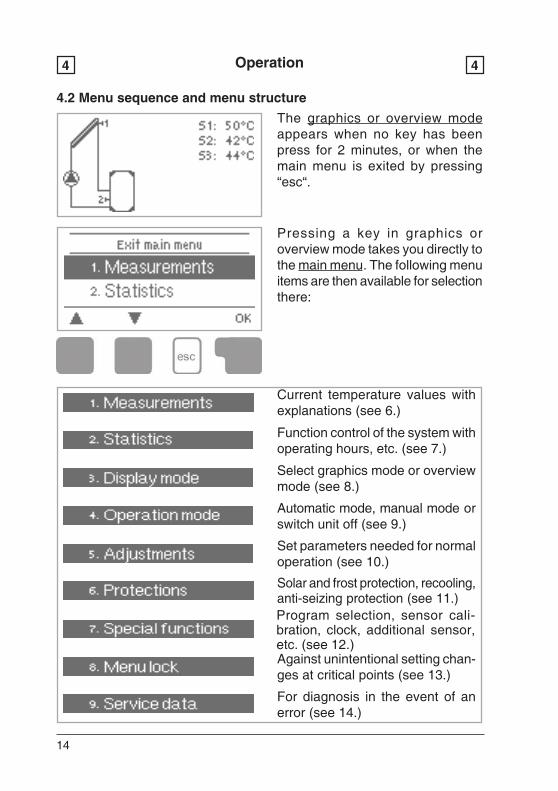
The graphics or overview modeappears when no key has beenpress for 2 minutes, or when themain menu is exited by pressing“esc“.
Pressing a key in graphics oroverview mode takes you directly tothe main menu. The following menuitems are then available for selectionthere:
Current temperature values withexplanations (see 6.)
Function control of the system withoperating hours, etc. (see 7.)
Select graphics mode or overviewmode (see 8.)
Automatic mode, manual mode orswitch unit off (see 9.)
Set parameters needed for normaloperation (see 10.)
Solar and frost protection, recooling,anti-seizing protection (see 11.)Program selection, sensor cali-bration, clock, additional sensor,etc. (see 12.)Against unintentional setting chan-ges at critical points (see 13.)
For diagnosis in the event of anerror (see 14.)
15
Parametrisation5 5
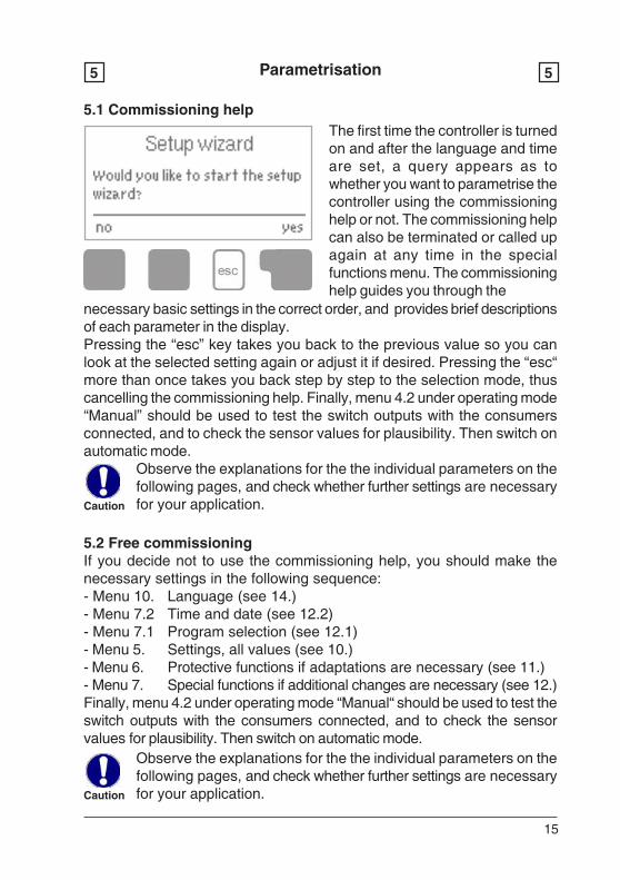
5.1 Commissioning help
Caution
Observe the explanations for the the individual parameters on thefollowing pages, and check whether further settings are necessaryfor your application.
5.2 Free commissioningIf you decide not to use the commissioning help, you should make thenecessary settings in the following sequence:- Menu 10. Language (see 14.)- Menu 7.2 Time and date (see 12.2)- Menu 7.1 Program selection (see 12.1)- Menu 5. Settings, all values (see 10.)- Menu 6. Protective functions if adaptations are necessary (see 11.)- Menu 7. Special functions if additional changes are necessary (see 12.)Finally, menu 4.2 under operating mode “Manual“ should be used to test theswitch outputs with the consumers connected, and to check the sensorvalues for plausibility. Then switch on automatic mode.
necessary basic settings in the correct order, and provides brief descriptionsof each parameter in the display.Pressing the “esc” key takes you back to the previous value so you canlook at the selected setting again or adjust it if desired. Pressing the “esc“more than once takes you back step by step to the selection mode, thuscancelling the commissioning help. Finally, menu 4.2 under operating mode“Manual” should be used to test the switch outputs with the consumersconnected, and to check the sensor values for plausibility. Then switch onautomatic mode.
Caution
Observe the explanations for the the individual parameters on thefollowing pages, and check whether further settings are necessaryfor your application.
The first time the controller is turnedon and after the language and timeare set, a query appears as towhether you want to parametrise thecontroller using the commissioninghelp or not. The commissioning helpcan also be terminated or called upagain at any time in the specialfunctions menu. The commissioninghelp guides you through the
16
Caution
Measurement values menu 16 6
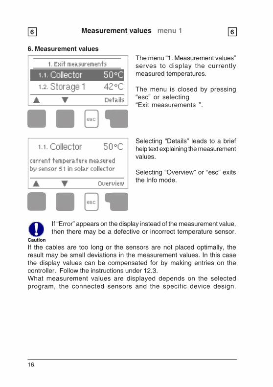
6. Measurement valuesThe menu “1. Measurement values”serves to display the currentlymeasured temperatures.
The menu is closed by pressing“esc” or selecting“Exit measurements ”.
Selecting “Details” leads to a briefhelp text explaining the measurementvalues.
Selecting “Overview” or “esc” exitsthe Info mode.
If “Error” appears on the display instead of the measurement value,then there may be a defective or incorrect temperature sensor.
If the cables are too long or the sensors are not placed optimally, theresult may be small deviations in the measurement values. In this casethe display values can be compensated for by making entries on thecontroller. Follow the instructions under 12.3.What measurement values are displayed depends on the selectedprogram, the connected sensors and the specific device design.
17
Statistics menu 27 7
7. Statistics
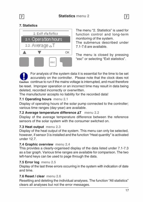
7.1 Operating hours menu 2.1Display of operating hours of the solar pump connected to the controller;various time ranges (day-year) are available.
7.3 Heat output menu 2.3
Display of the average temperature difference between the referencesensors of the solar system with the consumer switched on.
7.2 Average temperature difference ΔΔΔΔΔT menu 2.2
Display of the heat output of the system. This menu can only be selected,however, if sensor 3 is installed and the function “Heat quantity” is activatedunder 12.7.
7.4 Graphic overview menu 2.4This provides a clearly-organised display of the data listed under 7.1-7.3as a bar graph. Various time ranges are available for comparison. The twoleft-hand keys can be used to page through the data.
7.5 Error log menu 2.5
Resetting and deleting the individual analyses. The function “All statistics”clears all analyses but not the error messages.
7.6 Reset / clear menu 2.6
Display of the last three errors occurring in the system with indication of dateand time.
Caution
The menu “2. Statistics” is used forfunction control and long-termmonitoring of the system.The submenus described under7.1-7.6 are available.
The menu is closed by pressing“esc” or selecting “Exit statistics”.
For analysis of the system data it is essential for the time to be setaccurately on the controller. Please note that the clock does notcontinue to run if the mains voltage is interrupted, and must therefore
be reset. Improper operation or an incorrect time may result in data beingdeleted, recorded incorrectly or overwritten.The manufacturer accepts no liability for the recorded data!
18
Display mode menu 38 8
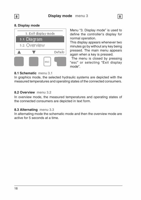
8. Display modeMenu “3. Display mode” is used todefine the controller’s display fornormal operation.This display appears whenever twominutes go by without any key beingpressed. The main menu appearsagain when a key is pressed. The menu is closed by pressing“esc” or selecting “Exit displaymode”.
8.1 Schematic menu 3.1In graphics mode, the selected hydraulic systems are depicted with themeasured temperatures and operating states of the connected consumers.
8.2 Overview menu 3.2In overview mode, the measured temperatures and operating states ofthe connected consumers are depicted in text form.
8.3 Alternating menu 3.3In alternating mode the schematic mode and then the overview mode areactive for 5 seconds at a time.
19
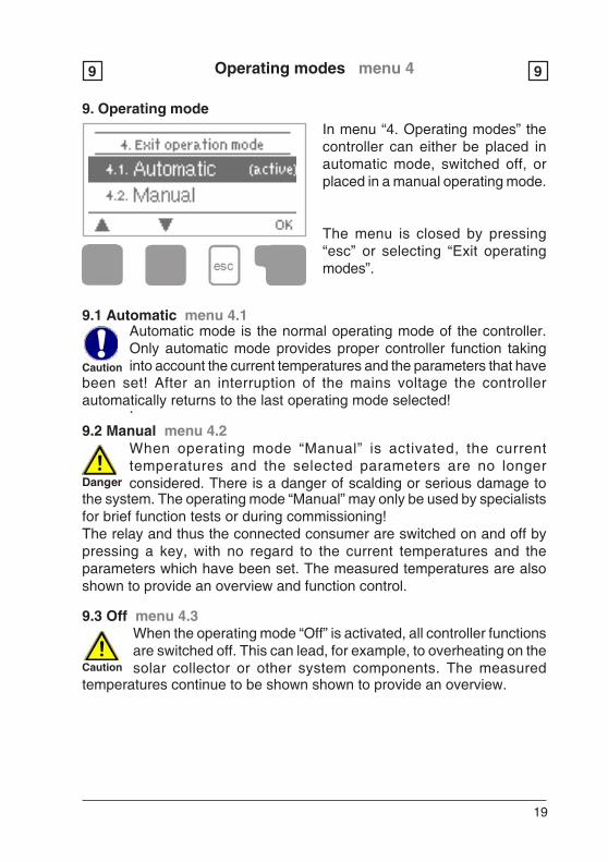
9. Operating modeIn menu “4. Operating modes” thecontroller can either be placed inautomatic mode, switched off, orplaced in a manual operating mode.
The menu is closed by pressing“esc” or selecting “Exit operatingmodes”.
Operating modes menu 49 9
Danger
When operating mode “Manual” is activated, the currenttemperatures and the selected parameters are no longerconsidered. There is a danger of scalding or serious damage to
.
the system. The operating mode “Manual” may only be used by specialistsfor brief function tests or during commissioning!The relay and thus the connected consumer are switched on and off bypressing a key, with no regard to the current temperatures and theparameters which have been set. The measured temperatures are alsoshown to provide an overview and function control.
9.2 Manual menu 4.2
9.3 Off menu 4.3When the operating mode “Off” is activated, all controller functionsare switched off. This can lead, for example, to overheating on thesolar collector or other system components. The measured
Automatic mode is the normal operating mode of the controller.Only automatic mode provides proper controller function takinginto account the current temperatures and the parameters that haveCaution
been set! After an interruption of the mains voltage the controllerautomatically returns to the last operating mode selected!
9.1 Automatic menu 4.1
Caution
temperatures continue to be shown shown to provide an overview.
20
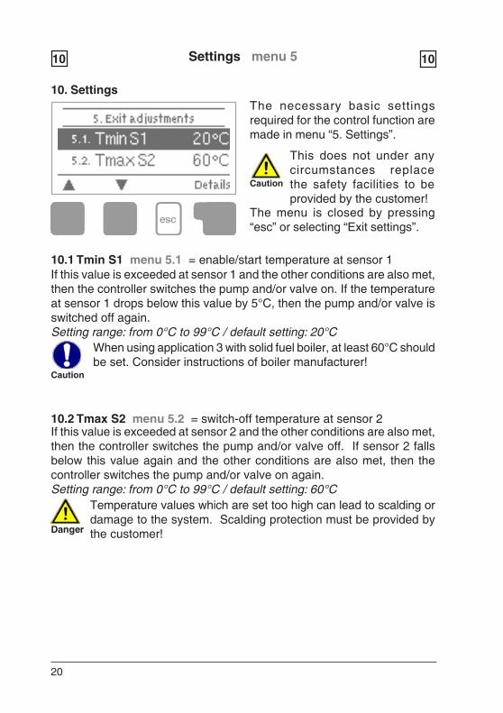
10. SettingsThe necessary basic settingsrequired for the control function aremade in menu “5. Settings”.
Danger
Temperature values which are set too high can lead to scalding ordamage to the system. Scalding protection must be provided bythe customer!
10.1 Tmin S1 menu 5.1 = enable/start temperature at sensor 1If this value is exceeded at sensor 1 and the other conditions are also met,then the controller switches the pump and/or valve on. If the temperatureat sensor 1 drops below this value by 5°C, then the pump and/or valve isswitched off again.Setting range: from 0°C to 99°C / default setting: 20°C
10.2 Tmax S2 menu 5.2 = switch-off temperature at sensor 2If this value is exceeded at sensor 2 and the other conditions are also met,then the controller switches the pump and/or valve off. If sensor 2 fallsbelow this value again and the other conditions are also met, then thecontroller switches the pump and/or valve on again.Setting range: from 0°C to 99°C / default setting: 60°C
Settings menu 510 10
Caution
When using application 3 with solid fuel boiler, at least 60°C shouldbe set. Consider instructions of boiler manufacturer!
Caution
This does not under anycircumstances replacethe safety facilities to beprovided by the customer!
The menu is closed by pressing“esc” or selecting “Exit settings”.

21
Settings menu 510 10
10.3 ΔΔΔΔΔT R1 menu 5.3 = switch-on temperature difference sensor1/sensor2If this temperature difference between sensor1 and sensor2 is exceededand the other conditions are also met, then the controller switches thepump and/or valve on. If the temperature difference between sensor1 andsensor2 drops to 1/3 of this value, then the pump and/or valve is switchedoff again.Setting range: 4°C to 20°C / default setting: 10°C
Caution
If the set temperature difference is too small, this may result inineffective operation or frequent clocking (switch-on and switch-off)of the pump.
22
Protective functions menu 611 11
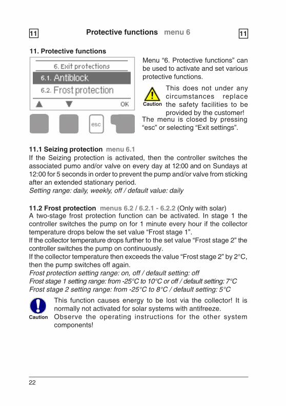
11. Protective functionsMenu “6. Protective functions” canbe used to activate and set variousprotective functions.
Caution
The menu is closed by pressing“esc” or selecting “Exit settings”.
This does not under anycircumstances replacethe safety facilities to beprovided by the customer!
11.1 Seizing protection menu 6.1If the Seizing protection is activated, then the controller switches theassociated pumo and/or valve on every day at 12:00 and on Sundays at12:00 for 5 seconds in order to prevent the pump and/or valve from stickingafter an extended stationary period.Setting range: daily, weekly, off / default value: daily
11.2 Frost protection menus 6.2 / 6.2.1 - 6.2.2 (Only with solar)
Caution
A two-stage frost protection function can be activated. In stage 1 thecontroller switches the pump on for 1 minute every hour if the collectortemperature drops below the set value “Frost stage 1”.If the collector temperature drops further to the set value “Frost stage 2” thecontroller switches the pump on continuously.If the collector temperature then exceeds the value “Frost stage 2” by 2°C,then the pump switches off again.Frost protection setting range: on, off / default setting: offFrost stage 1 setting range: from -25°C to 10°C or off / default setting: 7°CFrost stage 2 setting range: from -25°C to 8°C / default setting: 5°C
This function causes energy to be lost via the collector! It isnormally not activated for solar systems with antifreeze.Observe the operating instructions for the other systemcomponents!
23
11.3 Solar protection function menus 6.3 / 6.3.1 - 6.3.5 (Only with solar)Two solar protection variants V1+V2 and an alarm function with additionalsettings are available for the hydraulic systems with solar; these areexplained in more detail below.
Caution
Danger
In variant V1 the storage tank or the swimming pool is heated upover the value set under 10.2 “Tmax S2”, which can lead to scaldingand damage to the system.
Caution
In variant V2 elevated standstill temperatures and the correspondingsystem pressure are generated, which in some systems may leadto damage.
The solar protection is switched off at delivery. Please consult theoperating instructions for the system components for informationon whether and what solar protection variants the system requires.
Protective functions menu 611 11
Col. alarm menu 6.3.1If this temperature is exceeded at the collector sensor when the solarpump is on a warning or error message is triggered. The red light flashesand the corresponding warning appears in the display.Col. alarm - setting range: Off/60°C to 300°C / default setting: Off
SPF variant V1If the value “SPF T.on” is exceeded at the collector, the pump is switchedon to cool the collector. The pump is switched off if the value at the collectordrops bellow “SPF T.off” or the value “SPF Tmax stor.” is exceeded in thestorage tank.
SPF variant V2If the value “SPF Ton” is exceeded at the collector, the pump is switchedoff and not switched on again in order to protect the collector against steamblasts, etc. The pump is only switched on again when the value at thecollector drops below “SPF Toff”.
SPF variant setting range : V1, V2, off / default setting : OffSPF Ton setting range : from 60°C to 150°C / default setting: 110°CSPF Toff setting range : from 50°C to 145°C / default setting: 100°CSPF Tmax stor. setting range: from 0°C to 140°C / default setting: 90°C
24
11.5 Anti-Legionella menus 6.5 / 6.5.1 - 6.5.3
Caution
Danger
Caution
Protective functions menu 611 11
In hydraulic systems with solar when the recooling function is activatedexcess energy from the storage tank is fed back into the collector. Thisonly takes place if the temperature in the storage tank is higher than thevalue “Recool Tsetpoint” and the collector is at least 20°C cooler than thestorage tank and before the storage tank temperature has dropped belowthe value “Recool Tsetpoint”. In systems with two storage tanks the settingapplies to both storage tanks.Recooling setting range: on, off / default value: offRecooling Tsetpoint setting range: 0°C to 99°C / default value: 70°C
Caution
This function causes energy to be lost via the collector! Therecooling should only be activated in exceptional cases. Forexample with solar protection variant V1, since the storage tank
is overheated here, or during holidays when no heat is used.
11.4 Recooling menus 6.4 / 6.4.1 - 6.4.2 (Only with solar)
With the “AL function” activated the TDC1 makes it possible to heat thestorage tank up once at certain intervals (the “AL frequency”) to a highertemperature (“AL Tsetpoint S2”), assuming that the energy source allows this.
During the anti-Legionella function the storage tank is heated upover the set value “Tmax S2”, which can lead to scalding anddamage to the system.
This anti-Legionella function does not provide complete protectionagainst Legionella, because the controller is dependent on sufficientenergy being fed in, and it is not possible to monitor thetemperatures in the entire range of the storage tanks and theconnected piping system. To provide complete protection againstLegionella bacteria, it must be ensured that the temperature israised to the necessary temperature, and at the same time theremust be water circulation in the storage tank and piping system bymeans of other additional energy sources and control units.
The anti-Legionella function is switched off at delivery. This functionis only relevant for storage tanks where sensor 2 is installed.Whenever heating-up has been carried out with the anti-Legionellafunction is switched on, an information message with the dateappears on the display.
AL function setting range: On or Off / default setting: OffAL Tsetpoint S2 setting range: from 60°C to 99°C / default setting: 70°CAL frequency setting range: from 1 to 28 days / default setting: 7 daysAL heating: Shows the last time the Al function was active
25
Special functions menu 712 12
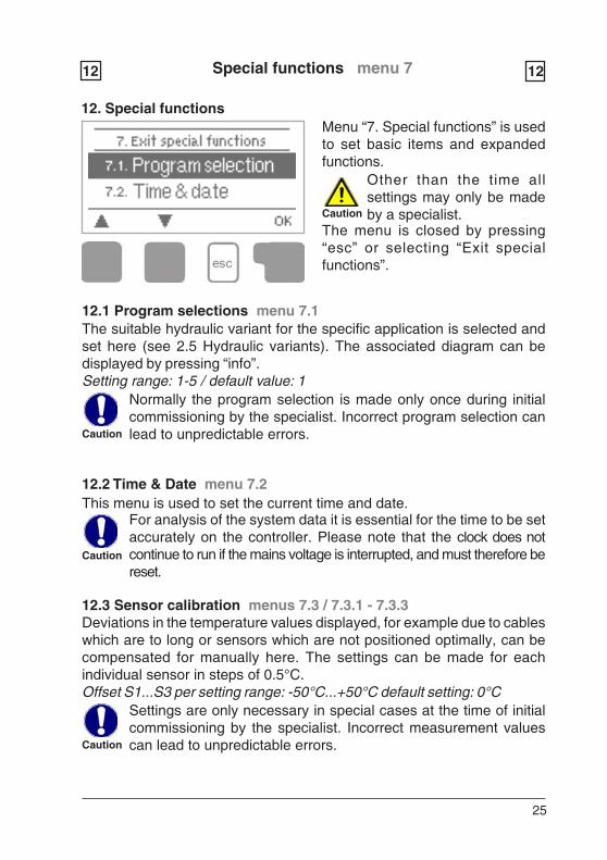
12. Special functionsMenu “7. Special functions” is usedto set basic items and expandedfunctions.
The menu is closed by pressing“esc” or selecting “Exit specialfunctions”.
12.1 Program selections menu 7.1The suitable hydraulic variant for the specific application is selected andset here (see 2.5 Hydraulic variants). The associated diagram can bedisplayed by pressing “info”.Setting range: 1-5 / default value: 1
Caution
12.2 Time & Date menu 7.2This menu is used to set the current time and date.
Caution
Normally the program selection is made only once during initialcommissioning by the specialist. Incorrect program selection canlead to unpredictable errors.
For analysis of the system data it is essential for the time to be setaccurately on the controller. Please note that the clock does notcontinue to run if the mains voltage is interrupted, and must therefore bereset.
Caution
12.3 Sensor calibration menus 7.3 / 7.3.1 - 7.3.3Deviations in the temperature values displayed, for example due to cableswhich are to long or sensors which are not positioned optimally, can becompensated for manually here. The settings can be made for eachindividual sensor in steps of 0.5°C.Offset S1...S3 per setting range: -50°C...+50°C default setting: 0°C
Caution
Settings are only necessary in special cases at the time of initialcommissioning by the specialist. Incorrect measurement valuescan lead to unpredictable errors.
Other than the time allsettings may only be madeby a specialist.
26
12.5 Factory settings menu 7.5All of the settings that have been made can be reset, thus returning thecontroller to its delivery state.
Caution
The entire parametrisation, analyses, etc. of the controller will belost irrevocably. The controller must then be commissioned onceagain.
Special functions menu 712 12
12.4 Commissioning menu 7.4Starting the commissioning help guides you in the correct order throughthe basic settings necessary for commissioning, and provides briefdescriptions of each parameter in the display.Pressing the “esc” key takes you back to the previous value so you canlook at the selected setting again or adjust it if desired. Pressing the “esc”more than once takes you back to the selection mode, thus cancelling thecommissioning help. (see also 5.1)
Caution
May only be started by a specialist during commissioning! Observethe explanations for the the individual parameters in theseinstructions, and check whether further settings are necessary foryour application.
12.6 Expansions menu 7.6 (only with expansions)This menu can only be selected and used if additional options orexpansions have been built into the controller.The associated supplementary installation, mounting and operationinstructions are then included with the specific expansion.12.7 Heat quantity menus 7.7 / 7.7.1 - 7.7.5A simple heat metering function for basic system control can be activatedin this menu. Additional settings regarding the glycol, the percentage ofgylcol and the flow rate of the system are required. A correction value forthe heat metering is also possible by adjusting the “Offset ΔT”
Keep in mind that the system is not changed, adjustments madein this menu are only used to calculate the heat volume and shouldbe based on the actual system. Resulting data is only approximatevalue for function control!
Heat metering menu 7.7.1Activate or deactivate the heat metering functionSettings range: On/off /default setting: Off
Caution
27
12.8 Start help function menus 7.8 / 7.8.1 - 7.8.3 (only with solar)With some solar systems, especially with vacuum tube collectors, it mayoccur that the measurement value acquisition at the collector sensoroccurs too slowly or too inaccurately because the sensor is often not atthe hottest location. When the start help is activated the following sequenceis carried out:If the temperature at the collector sensor increases by the value specifiedunder “Increase” within one minute, then the solar pump is switched on forthe set “Purging time” so that the medium to be measured can be movedto the collector sensor. If this still does not result in a normal switch-oncondition, then the start help function is subject to a 5-minute lockout time.Start help setting range: on, off/default setting: offPurging time setting range: 2 ... 30 sec./default setting: 5 sec.Increase setting range: 1°C....10°C/default setting: 3°C/min.
Caution
This function should only be activated by a specialist if problemsarise with acquisition of measurement values. In particular followthe instructions from the collector manufacturer.
Special functions menu 712 12
AF type menu 7.7.2Adjust the type of glycol that has been used in the system.Settings range: Ethylene/Propylene /default setting: Ethylene
Glycol portion menu 7.7.3Adjust the percentage of glycol that has been used in the system.Settings range: 0-60% /default setting: 40%
Flow rate menu 7.7.4Adjust the flow rate according to the system.Settings range: 10-5000 l/h /default setting: 500 l/h
ΔΔΔΔΔT Offset menu 7.7.5Since the calculation of the heat metering is based on the temperature ofthe collector and storage where measuring takes place, a possible deviationfrom the flow and return temperature can be compensated with this value.Example: Displayed collector temp. 40° C, measured flow temp. 39° C,displayed storage temp. 30° C, measured return temp. 31° C means asetting of -20% (Displayed ΔT 10K, actual ΔT 8K => -20% correction value)Settings range: -50% to +50% /default settings: 0%
28
Menu lock menu 813 13
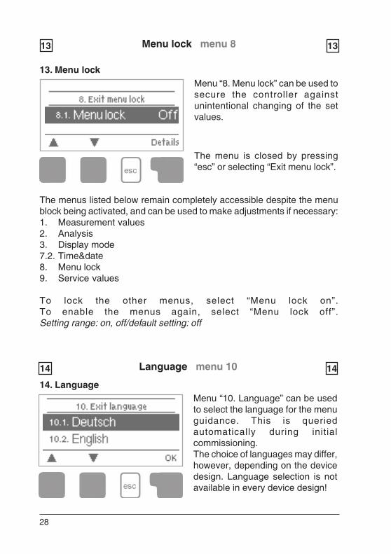
13. Menu lockMenu “8. Menu lock” can be used tosecure the controller againstunintentional changing of the setvalues.
The menu is closed by pressing“esc” or selecting “Exit menu lock”.
The menus listed below remain completely accessible despite the menublock being activated, and can be used to make adjustments if necessary:1. Measurement values2. Analysis3. Display mode7.2. Time&date8. Menu lock9. Service values
To lock the other menus, select “Menu lock on”.To enable the menus again, select “Menu lock off”.Setting range: on, off/default setting: off
Language menu 1014 14
Menu “10. Language” can be usedto select the language for the menuguidance. This is queriedautomatically during initialcommissioning.The choice of languages may differ,however, depending on the devicedesign. Language selection is notavailable in every device design!
14. Language
29
Service values menu 915 15
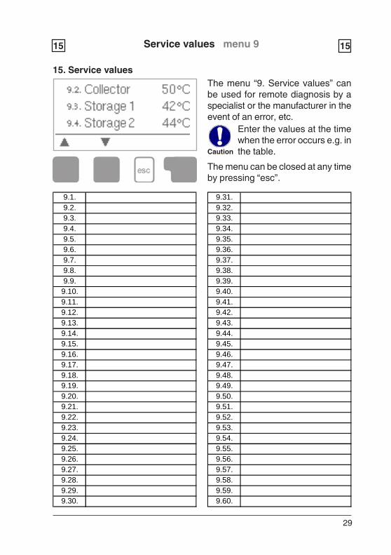
15. Service valuesThe menu “9. Service values” canbe used for remote diagnosis by aspecialist or the manufacturer in theevent of an error, etc.
Caution
Enter the values at the timewhen the error occurs e.g. inthe table.
The menu can be closed at any timeby pressing “esc”.
9.1.9.2.9.3.9.4.9.5.9.6.9.7.9.8.9.9.9.10.9.11.9.12.9.13.9.14.9.15.9.16.9.17.9.18.9.19.9.20.9.21.9.22.9.23.9.24.9.25.9.26.9.27.9.28.9.29.9.30.
9.31.9.32.9.33.9.34.9.35.9.36.9.37.9.38.9.39.9.40.9.41.9.42.9.43.9.44.9.45.9.46.9.47.9.48.9.49.9.50.9.51.9.52.9.53.9.54.9.55.9.56.9.57.9.58.9.59.9.60.
30
Malfunctions16 16
16.1 Malfunctions with error messages
Possible error messages:
Sensor x defective ——————>
Collector alarm ———————>
Night circulation ———————>
Restart ———————————>
Time&date ——————————>
(Led flashes +warning symbol)
Danger
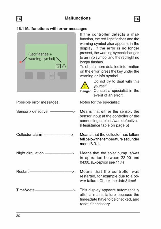
If the controller detects a mal-function, the red light flashes and thewarning symbol also appears in thedisplay. If the error is no longerpresent, the warning symbol changesto an info symbol and the red light nolonger flashes.To obtain more detailed informationon the error, press the key under thewarning or info symbol.
Notes for the specialist:
Means that either the sensor, thesensor input at the controller or theconnecting cable is/was defective.(Resistance table on page 5)
Means that the collector has fallen/fell below the temperature set undermenu 6.3.1.
Means that the solar pump is/wasin operation between 23:00 and04:00. (Exception see 11.4)
Means that the controller wasrestarted, for example due to a po-wer failure. Check the date&time!
This display appears automaticallyafter a mains failure because thetime&date have to be checked, andreset if necessary.
Do not try to deal with thisyourself.Consult a specialist in theevent of an error!
31
16.2 Replacing the fuse
Malfunctions16 16
Danger
Danger
Fig.3.1.1
Fuse
16.3. Maintenance
Caution
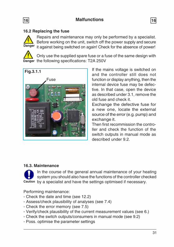
If the mains voltage is switched onand the controller still does notfunction or display anything, then theinternal device fuse may be defec-tive. In that case, open the deviceas described under 3.1, remove theold fuse and check it.Exchange the defective fuse fora new one, locate the externalsource of the error (e.g. pump) andexchange it.Then first recommission the contro-ller and check the function of theswitch outputs in manual mode asdescribed under 9.2.
Repairs and maintenance may only be performed by a specialist.Before working on the unit, switch off the power supply and secureit against being switched on again! Check for the absence of power!
Only use the supplied spare fuse or a fuse of the same design withthe following specifications: T2A 250V
In the course of the general annual maintenance of your heatingsystem you should also have the functions of the controller checkedby a specialist and have the settings optimised if necessary.
Performing maintenance:- Check the date and time (see 12.2)- Assess/check plausibility of analyses (see 7.4)- Check the error memory (see 7.5)- Verify/check plausibility of the current measurement values (see 6.)- Check the switch outputs/consumers in manual mode (see 9.2)- Poss. optimise the parameter settings
32
L:\B
edie
nanl
eitu
ngen
\SO
RE
L\T
DC
\TD
C1
Eng
lisch
\TD
C1
engl
ish
7201
1\T
DC
1 en
glis
h 72
011.
Manufacturer: Your specialist dealer:
Notes:
SOREL GmbH MikroelektronikJahnstr. 36D - 45549 SprockhövelTel. +49 (0)2339 6024Fax +49 (0)2339 6025www.sorel.de [email protected]
Hydraulic variant set:
Commissioned on:
Commissioned by:
Final declaration:Although these instructions have been created with the greatest possiblecare, the possibility of incorrect or incomplete information cannot beexcluded. Subject as a basic principle to errors and technical changes.