tempering processes & technology · pdf filetempering processes/technology conventional...
TRANSCRIPT
Tempering Processes/Technology
Conventional Processes Tempering is a process in which previously hardened or normalized steel
is usually heated to a temperature hclocr the IOU er critical temperature and cooled al a suilable rate. primarily to increase ductility and toughness. hut also to increase the grain size of the matrix. Steels are tempered b) reheating after hardening to obtain specific Lalues of mechanical properties and also to relieve quenching stresses and to ensure dimensional stahilitj. Tempering usually follows quenching from above the upper critical tem- perature; hoNever, tempering is also used to relieve the stresses and reduce the hardness developed during ueldinp and to relisve stresses induced b) fomling and machining.
Principal Variables Variables that affect the microstructure and the mechanical properties of
a tempered steel include:
l Tempering temperature l Time at temperature l Cooling rate from the tempering temperature
l Composition of the steel. including carbon content, alloy content, and residual elements
ln a steel quenched to a microstructure consisting essentially of martensite, the iron lattice is strained b) the carbon atoms, producing the high hardness of quenched steels.
Under certain conditions. hardness may remain unaffected hy tempering or may even be increased as a result of it. For example, tempering a hardened steel at I eq low tempering temperatures may cause no change in hardness but may achieve a desired increase in yield strength. Also, those allo) steels that contain one or more of the carhide-forming elements (chromium. molybdenum. vanadium. and tungsten) are capable of secon- dq hardening: that is. they ma) become somewhat harder as a result of tempering.
The tempered hardness \ alues for se\ eral quenched steels are presented in an adjoining Table. Temperature and time are interdependent variables in the tempering process. Within limits. lowering temperature and increas- ing time can usualI! produce the same result as raising temperature and decreasing time. However, minor temperature changes have a far greater
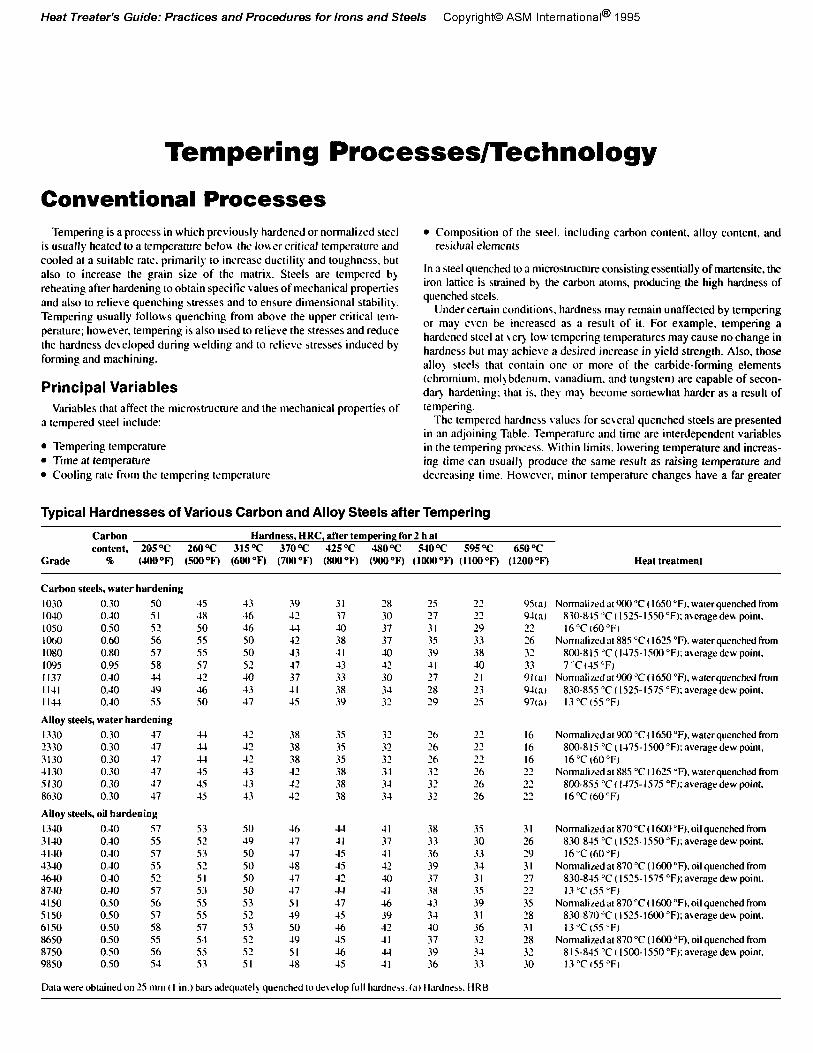
Typical Hardnesses of Various Carbon and Alloy Steels after Tempering
Grade
Carbon Hardness, HRC, after temperiag for 2 hat content, 205 T 260 ‘=C 315T 37OT J25T 48OT -540 T 595 T 650 T
k (.WO”F) (500°F) (6OOT) (700°Fj @OO°F) (9OO’=F) (lOOO°F) (1100°F) (1200°F) Heat treatment
Carbon steels, water hardening
1030 0.30 SO I040 0.40 51 1050 0.50 s2 lob0 0.60 56 1080 0.80 57 IO??5 0.95 ss 11.37 0.30 44 IIJI O.-IO 19 1131 0.40 55
Alloy steels, water hardening
1330 0.30 47 2330 0.30 47 3130 0.30 47 1130 0.30 47 Sl30 0.30 37 8h.30 0.30 47
Alloy steels, oil hardening
1340 O.-IO 57 31-U) 0.10 55 4140 0.40 57 4340 0.10 55 ul-lo O.-IO 51 8740 0.40 57 4150 0.50 56 5150 0.50 57 6150 OS0 58 8650 050 ss 8750 o.so 56 9850 050 51
45 48 50 ss 55 57 42 46 so
13 46 16 SO SO 51 40 13 47
39 42 4-l 42 43 -17 37 II 4s
31 37 40 38 II 43 33 38 39
28 30 37 37 40 -12 30 31 32
‘5 ‘7 31 3s 39 -II 27 28 29
s3 50 46 4-t II 38 35 52 49 17 -II 37 33 30 s3 50 17 15 41 36 33 5’ ii so 50 48 17 45 42 41 40 37 39 3-l 31 53 50 17 +I II 38 35 55 53 51 17 46 43 39 55 52 19 45 39 3-I 31 57 53 SO 46 1’ 40 36 5-l s2 49 4s -II 37 32 55 5’
ii 51 46 4-t 39 3-t
5.3 18 1s II 36 33
9513) Normalized at 900°C (1650°F). waterquenched from 94cIJ 830~X-iS“C( l525-15SO”F):s~eragedea point. 72 16”Cl60”F, 26 Normalized a~ 885 “C I I625 “F). water quenched From 7’ ;;
800-81.5 “C (1175.15OO”F):a\rrage dew poim. 7“Ct4S”F)
91ta1 Normali~dur 900 “C Il650”F~. waterquenched from 943) 830-855 “C 1 I SZS- I S7S “F); average dew point. 97w lB”Cl55”F1
I6 Normtired at 900 “C ( 1650°F). water quenched fmm I6 800-815 “C(I-175-1500”F):a\er~gedew point, I6 16”Ct6O”F) 22 Normalized at 88S “C ( 1625 OF), water quenched from ‘2 8004355 “Cl l-l7S-lS7S “F);areragedew point. 22 I6 “C (60 “F)
31 16 19 31 27 37
ii 18 31 28 3’ lo
Normalized at 870 “C t 1600 “F). oil quenched hum X30-849 “C I ISIS- I550 “F); average dew point. l6’>C (60°F)
Normalized at 870 “C (1600 “F). oil quenched from 830-845 “C ( 1525. I575 “F): average dew point. I3 “C (5.5 “F)
Normalizcda1870”C( 1600”F),oiIquenchedfrom 830-870 ‘C t I SZS- I600 “F); aLerage deu point. 13”CtSS’F)
Normalized at 870 “C ( 1600°F). oil quenched from 8 1%845 “C t IYJO- lSSO”F): average dew point. 13”C155”F,
Data were obtained on 25 null t I in.) bars adequateI) quenched wdc\elop full hzdnejs. (a~ Hardness. HRB
effect than minor time changes in typical tempering operations. With few exceptions, tempering is done at temperatures between 175 and 705 “C (315 and I300 “F) and for times from 30 min to 1 h.
Structural Changes. Based on x-ray, dilatometric. and microstructu- ral studies, there are three distinct stages of tempering, even though the temperature ranges overlap (Ref I-4):
l Stage I: The formation of transition carbides and lobering of the carbon content of the martensite to 0.1SQ ( 100 to 250 “C, or 310 to 480 “F)
l Stage II: The transformation of retained austenite 10 ferrite and cementite (200 to 300 “C. or 390 to 570 “F)
l Stage IfI: The replacement of transition carbides and low-temperature martensite by cementite and ferrite (250 to 350 “C. or 180 to 660 “F)
An additional stage of tempering (stage IV). precipitation of fineI> dispersed alloy carbides, exists for high-alloy steels. It has been found that stage I of tempering is often preceded by the redistribution of carbon atoms. called autotempering or quench tempering, during quenching and/or hold- ing at room temperature (Ref 5). Other structural changes take place because of carbon atom rearrangement preceding the classical stage I of tempering (Ref 6,7).
Dimensional Changes. Martensite transformation is associated with an increase in volume. During 1empering. martensite decomposes into a mixture of ferrite and cementite with a resultant decrease in volume as tempering temperature increases. Because a 100% martensitic structure after quenching cannot always be assumed, volume may not continuous11 decrease with increasing tempering temperature.
The retained austenite in plain carbon steels and low-alloy steels trans- forms to bainite with an increase in volume, in stage II of tempering. When certain alloy steels are tempered. a precipitation of finely distributed allo) carbides occurs. along with an increase in hardness, called secondq hardness, and an increase in volume. With the precipitation of allo) car- bides. the MS temperature (temperature at which martensite starts to foml from austenite upon cooling) of the retained austenite will increase and transform to martensite during cooling from the tempering temperature.
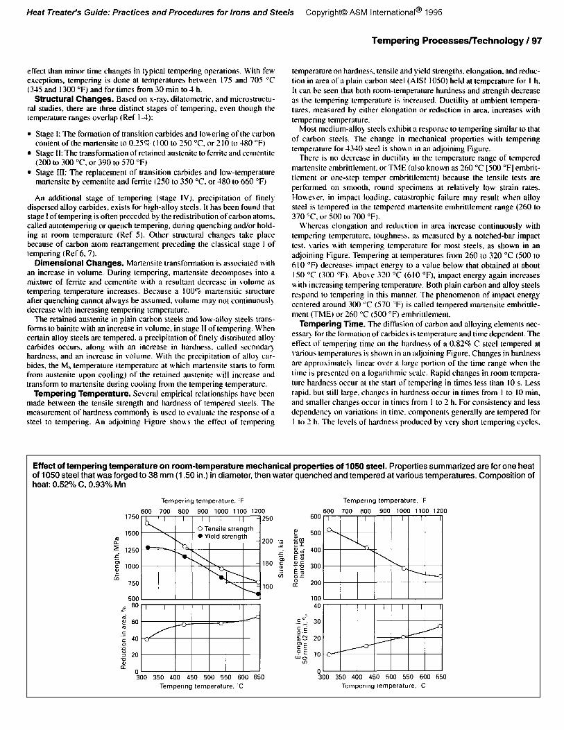
Tempering Temperature. Several empirical relationships have been made between the tensile strength and hardness of tempered steels. The measurement of hardness commonI> is used to evaluate the response of a steel to tempering. An adjoining Figure shous the effect of tempering
Tempering Processes/Technology / 97
temperature on hardness, tensile and yield strengths, elongation, and reduc- tion in area of a plain carbon steel (AISI 1050) held at temperature for I h. It can be seen that both room-temperature hardness and strength decrease as the tempering temperature is increased. Ductility at ambient tempera- tures. measured by either elongation or reduction in area, increases with tempering temperature.
hlost medium-allo) steels exhibit a response to tempering similar to that of carbon steels. The change in mechanical properties with tempering temperature for 4330 steel is shorn n in an adjoining Figure.
There is no decrease in ductility in the temperature range of tempered martensite embrittlement. or ThIE (also known as 160 “C [SO0 “F] embrit- tlsment or one-step temper embrittlement) because the tensile tests are performed on smooth. round specimens at relatively low strain rates. Home\sr. in impact loading. catastrophic failure may result when alloy steel is tempered in the tempered martensite embrittlement range (260 to 370 “C. or SO0 to 700 “F).
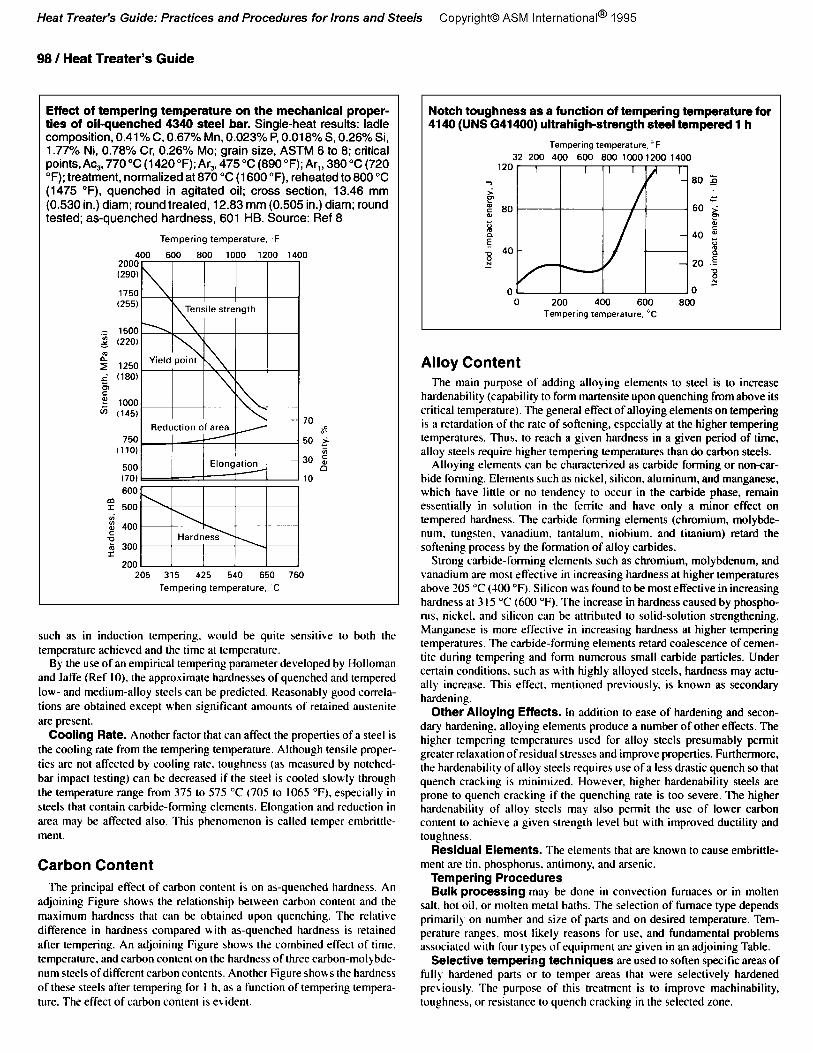
H’hereas elongation and reduction in area increase continuously with tempering temperature. toughness. as measured by a notched-bar impact test. \ aries uith tempering temperature for most steels, as shown in an adjoining Figure. Tempering at temperatures from 260 to 320 “C (500 to 610 “F) decreases impact energy to a value below that obtained at about IS0 “C (300 “F). Above 320 “C (610 “F), impact energy again increases mith increasing tempering temperature. Both plain carbon and alloy steels respond IO tempering in this manner. The phenomenon of impact energy centered around 300 YY (570 ‘Fj is called tempered martensite embrittle- ment (ThlE) or 160 “C (SO0 “F) embrittlement.
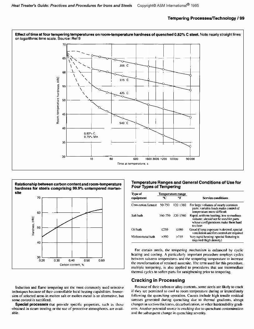
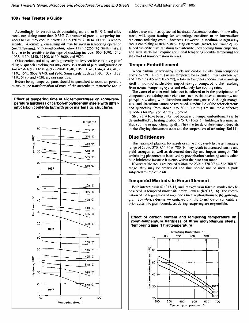
Tempering Time. The difision of carbon and alloying elements nec- essarj for the formation of carbides is temperature and time dependent. The effect of tempering time on the hardness of a 0.828 C steel tempered at various temperatures is shown in an adjoining Figure. Changes in hardness are approximateI) linear over a large portion of the time range when the time is presented on a logarithmic scale. Rapid changes in room tempera- ture hardness occur at the start of tempering in times less than IO s. Less rapid. but still large. changes in hardness occur in times from I to IO min. and smaller changes occur in times from I IO 2 h. For consistency and less dependency on variations in time. components generally are tempered for I to 2 h. The levels of hardness produced by very short tempering cycles,
Effect of tempering temperature on room-temperature mechanical properties of 1050 steel. Properties summarized are for one heat of 1050 steel that was forged to 38 mm (1 SO in.) in diameter, then water quenched and tempered at various temperatures. Composition of heat: 0.52% C, 0.93% Mn
98 / Heat Treater’s Guide
Effect of tempering temperature on the mechanical proper- ties of oilquenched 4340 steel bar. Single-heat results: ladle composition, 0.41% C. 0.67% Mn, 0.023% P, 0.018% S, 0.26% Si, 1.77% Ni, 0.78% Cr, 0.26% MO; grain size, ASTM 6 to 8; critical pointsAc,, 770°C (1420”F);Ar,, 475°C (890°F); Ar,, 380°C (720 “F); treatment, normalized at 870 “C (1600 “F), reheated to 800 “C (1475 “F), quenched in agitated oil; cross section, 13.46 mm (0.530 in.) diam; round treated, 12.83 mm (0.505 in.) diam; round tested; as-quenched hardness, 601 HB. Source: Ref 8
such as in induction tempering, would be quite sensitive to both the temperature achieved and the time at temperature.
By the use of an empirical tempering parameter developed by Holloman and Jaffe (Ref IO), the approximate hardnesses of quenched and tempered low- and medium-alloy steels can be predicted. Reasonably good correla- tions are obtained except when significant amounts of retained austenite are present.
Cooling Rate. Another factor that can affect the properties of a steel is the cooling rate from the tempering temperature. Although tensile proper- ties are not affected by cooling rate. toughness (as measured by notched- bar impact testing) can be decreased if the steel is cooled slowly through the temperature range from 375 to 575 “C (705 to 1065 OF). especially in steels that contain carbide-forming elements. Elongation and reduction in area may be affected also. This phenomenon is called temper embrittle- ment.
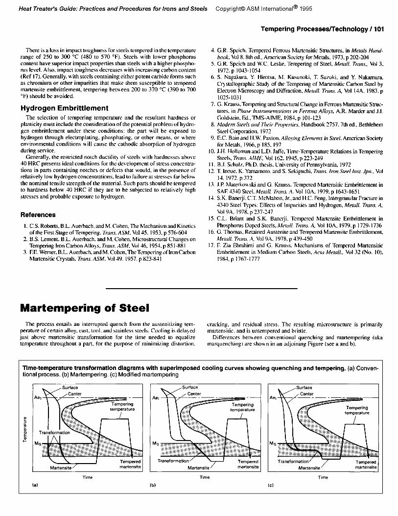
Carbon Content The principal effect of carbon content is on as-quenched hardness. An
adjoining Figure shows the relationship between carbon content and the maximum hardness that can be obtained upon quenching. The relative difference in hardness compared with as-quenched hardness is retained after tempering. An adjoining Figure shows the combined effect of time. temperature, and carbon content on the hardness of three carbon-molybde- num steels of different carbon contents. Another Figure shows the hardness of these steels after tempering for I h. as a function of tempering tempera- ture. The effect of carbon content is evident.
Notch toughness as a function of tempering temperature for 4140 (UNS G41400) ultrahigh-strength steel tempered 1 h
Alloy Content The main purpose of adding alloying elements to steel is to increase
hardenability (capability to form martensite upon quenching from above its critical temperature). The genera) effect of alloying elements on tempering is a retardation of the rate of softening, especially at the higher tempering temperatures. Thus. to reach a given hardness in a given period of time, alloy steels require higher tempering temperatures than do carbon steels.
Alloying elements can be characterized as carbide forming or non-car- bide forming. Elements such as nickel, silicon, aluminum. and manganese, which have little or no tendency to occur in the carbide phase, remain essentially in solution in the ferrite and have only a minor effect on tempered hardness. The carbide forming elements (chromium, molybde- num. tungsten, vanadium, tantalum. niobium, and titanium) retard the softening process by the formation of alloy carbides.
Strong carbide-forming elements such as chromium, molybdenum, and vanadium are most effective in increasing hardness at higher temperatures above 205 “C (100 “F). Silicon was found to be most effective in increasing hardness at 3 I5 “C (600 “Fj. The increase in hardness caused by phospho- rus, nickel. and silicon can be attributed to solid-solution strengthening. Manganese is more effective in increasing hardness at higher tempering temperatures. The carbide-forming elements retard coaJescence of cemen- tite during tempering and foml numerous small carbide particles. Under certain conditions, such as with highly alloyed steels, hardness may actu- ally increase. This effect, mentioned previously. is known as secondary hardening.
Other Alloying Effects. In addition to ease of hardening and secon- dary hardening. alloying elements produce a number of other effects. The higher tempering temperatures used for alloy steels presumably permit greater relaxation of residual stresses and improve properties. Furthermore, the hardenability of alloy steels requires use of a less drastic quench so that quench cracking is minimized. However, higher hardenability steels are prone to quench cracking if the quenching rate is too severe. The higher hardenability of alloy steels may also permit the use of lower carbon content to achieve a given strength level but with improved ductility and toughness.
Residual Elements. The elements that are known to cause embrittle- ment are tin. phosphorus. antimony, and arsenic.
Tempering Procedures Bulk processing may be done in convection furnaces or in molten
salt. hot oil. or molten metal baths. The selection of furnace type depends primarily on number and size of parts and on desired temperature. Tem- perature ranges. most likely reasons for use. and fundamental problems associated with four types of equipment are given in an adjoining Table.
Selective tempering techniques ;LTe used to soften specific areas of fully hardened parts or to temper areas that were selectively hardened previously. The purpose of this treatment is to improve machinability, toughness, or resistance to quench cracking in the selected zone.
Tempering Processes/Technology / 99
Effect of time at four tempering temperatures on room-temperature hardness of quenched 0.82% C steel. Note nearly straight lines on logarithmic time scale. Source: Ref 9
site
Relationship between carbon content and room-temperature hardness for steels comprising 99.9% untempered marten-
Induction and flame tempering are the most commonly used seleclive techniques because of their controllable local heating capabilities. Immer- sion of selected areas in molten salt or molten metal is an alternative. but some control is sacriliced.
Special processes that provide specitic properties. such as those obtained in steam treating or the use of protective atmospheres. are avail- able.
Temperature Ranges and General Conditions of Use for Four Types of Tempering
PP of Temperature range equipment OC OF Service conditions
Comection furnace SO-750 I70- I380 For large volumes of nearly common parts: variable loads m&e control of lemperattw moredifficul~
Salt bath l6O-7SO 320. I380 Rapid. uniform heating; low to medium volume; should not be used for parts whose configurations make them hard toclean
Oil hath <‘TO --_ S-l-180 Good if long exposure is desired; special ventilation and fire control are required
Molten meud bath >390 >735 Very rapid heating: special fixhning is reauired (high densiw)
For certain steels, the tempering mechanism is enhanced by cyclic healing and cooling. A particularly important procedure employs cycles between subzero temperatures and the tempering temperature to increase the transformation of retained austenite. The term used for this procedure. multiple tempering, is also applied to procedures that use intermediate thermal cycles to soften parts for straightening prior to tempering.
Cracking in Processing Because of their carbon or alloy contents, some steels are likely to crack
if they are permitted to cool to room temperature during or immediately following the quenching operation. Causes include high tensile residual stresses generated during quenching due to thermal gradients. abrupt changes in section thickness, decarburization, or other hardenability gradi- ents. Another potential source is cracking due to quenchant contamination and the subsequent change in quenching severity.
100 / Heat Treater’s Guide
Accordingly. for carbon steels containing more than 0.4% C and alloy achieve maximum as-quenched hardness. Austenite retained in low-alloy sleek containing more than 0.35% C. transfer of parts to tempering fur- steels will. upon healing for tempering, transform to an intermediate
naces hefore they cool to below 100 to IS0 “C (210 LO 300 “F) is recom- structure. reducing overall hardness. However. in medium- to high-alloy
mended. Alternately, quenching oil may he used in tempering operation steels containing austenite-stabilizing elements (nickel. for example). re-
(martempering), or 10 avoid cooling below I25 “C (255 “F). Steels that are tained austcnite may transform LO martensile upon cooling From tempering,
known to be sensitive IC) this type of cracking include 1060. 1090. 1340, and such steels may require additional tempering (double tempering) for
1063.4 I SO. 3340,52 IOO,6 I SO. 8650, and 9850. the relief of transformation stresses.
Other carbon and alloy steels generally are less sensitive to Uris type of delayed quench cracking but may crack as a result of part configuranon or surface defects. These steels include 1030. 1050. I I-II. I I-L!. -W7.-ll32. -I I10.4640.8632.8710. and 9840. Some steels, such as 1020. 1038, I IX. 1130. 5 130. and 8630. are not sensitive.
Temper Embrittlement
Before being lempered. parts should be quenched to room temperature to ensure the transformation of most of the austenhe to martensite and to
When carbon or low-alloy steels are cooled slowly from tempering ahove 575 ‘C ( 1065 “F) or are tempered for extended times between 375 and 575 “C (70s and 1065 “F). a loss in toughness occurs that manifests itself in reduced notched-bar impact strength compared IO that resulting from normal tempering cycles and relativelv fast cooling rates.
Effect of tempering time at six temperatures on room-tem- aerature hardness of carbon-molybdenum steels with differ- znt carbon contents but with prior martensitic structures
The cause of temper embrinlement is belkved 10 be the precipitation of compounds containing trace elements such as tin, arsenic. antimony, and phosphorus, along with chromium and/or manganese. Although manga- nese and chromium cannot he restricted. a reduction of the other elements and quenching from ahove 575 “C (I065 “F) are the most effecuve remedies for this type of embrittlement.
Steels that have been embrittled because of temper embrinlement can he de-embritkd by heating 10 about 575 ‘C ( 1065 “F). holding a few minutes. then cooling or quenching rapidly. The time for de-embrittlemen~ depends on the alloying elements presenr and the temperature of reheating (Ref I I).
Blue Brittleness The heating of plain carbon steels or some alloy steels to the temperature
range of 230 to 370 ‘C (-US to 700 “F) ma,y.result in increased tensile and yield strength. as well as decreased ducuhty and impact strength. This embrittling phenomenon is caused by precipitation hardening and is called blue brittleness because it occurs within the blue heat range.
If susceptible steels are heated H ithin the 230 IO 370 “C (US to 700 “F) range. they may be embrittled and thus should not be used in pru~s suhjrcted to impact loads.
Tempered Martensite Embrittlement Both inrergranular (Ref I3- IS) and transgranular fracture modes may be
observed in tempered martensite embrittlement (Ref 13, 16). The comhi- nation of the segregation of impurities such as phosphorus to the austenitic grain boundaries during austenitizing and the formation of cementite at prior austenitic grain boundaries during tempering are responsible.
Effect of carbon content and tempering temperature on room-temperature hardness of three molybdenum steels. Tempering time: 1 h at temperature
There is a loss in impact toughness for steels tempered in the temperature range of 250 to 300 “C (380 to 570 OF). Steels with lower phosphorus content have superior impact properties than steels with a higher phospho- rus level. Also. impact toughness decreases with increasing carbon content (Ref 17). Generally, with steels containing either potent carbide forms such as chromium or other impurities that make them susceptible to tempered martensite embrittlement, tempering between 200 to 370 “C (390 to 700 “F) should be avoided.
Hydrogen Embrittlement The selection of tempering temperature and the resultant hardness or
plasticity must include the consideration of the potential problem of hydro- gen embrittlement under these conditions: the part will be exposed to hydrogen through electroplating. phosphating, or other means. or where environmental conditions will cause the cathodic absorption of hydrogen during service.
Generally, the restricted notch ductilit) of steels with hardnesses above 10 HRC presents ideal conditions for the development of stress concentra- tions in parts containing notches or defects that would. in the presence of relatively low hydrogen concentrations. lead to failure at stresses far below the nominal tensile strength of the material. Such parts should be tempered to hardness below 10 HRC if they are to be subjected to relatively high stresses and probable exposure to hydrogen.
References
I. C.S. Roberts, B.L. Auerbach. and M. Cohen, The Mechanism and Kinetics of the Fit Stage of Tempering. Trarrs. ASM, Vol35. 1953, p 576-60-I
2. B.S. Lement. B.L. Auerbach. and hf. Cohen, Microstructural Changes on Tempering iron Carbon Alloys, Trarrs. ASM. Vol46. 19%. p 85 l-88 I
3. F.E. Werner. B.L. Auerbach. and M. Cohen, TheTempering of iron Carbon Martensitic Crystals. Trans. ASI%~. Vol-19. 1957. p 823-841
Tempering Processee/Technology / 101
4. G.R. Speich. Tempered Ferrous hlartensitic Structures. in Mm/s Hurui- book. Vol8,8th ed., American Society for Metals, 1973, p 202-204
5. G.R. Speich and WC. Leslie. Tempering of Steel, Merd. Trms., Vol 3, 197’. p l@l3-1054
6. S. Nagakwra. Y. Hirotsu. hl. Kusunoki. T Suzuki, and Y. Nakarnura, C~stallog~aphic Stud> of the Tempering of hlartensitic Carbon Steel by Electron hlkroscopy and Diffraction. hfe!o/l. Trorrs. A, Vol I4A. 1983, p 1025-1031
7. G. Krauss. Tempering and Structural Change in Ferrous Martensitic Strut- tures. in Ptme Insrrlrtt,u~nroriorls in Fertms Allop, A.R. Marder and J.I. Goldstein. Ed., TMS-AIhlE. 198-l. p 101-123
8. Modem Sleek cm/ Ttreir Propenies. Handbook 3757.7th ed., Bethlehem Steel Corporation, 1972
9. EC. Bain and H.W. Paston. Altq\ing Ekarrrm in Steel. Anlerican Society for hletds, 1966, p 185, 197
IO. J.H. Holloman and L.D. Jaffe. Tie-Temperature Relations in Tempering Steels, Trans. A/ME, Vol 162. 1945, p 223-249
I I B.J. Schulz. Ph.D. thesis. University of Pennsylvania. 1972 I?. T. lnoue, K. Yamamoto. and S. Seki;ieuchi. Trms. /ml Srrel Insr. Jp., Vol
I-l. 1972. p 372 13. J.P. hlaterko~sski and G. Krauss. Tempered hlartensitic Embrittlement in
SAE -tNO Steel, hferd. Trczrrs. 4. Vol IOA. 1979. p 1643-1651 I-4. SK. Bane@. C.T. hlcMahon. Jr., and H.C. Feng. lnter~ular Fracture in
4340 Steel Types: Effects of Impurities and Hydrogen, Me&l. Trms. A, Vol9A. 1978. p 737-347
IS. C.L. Briant and S.K. Banerji. Tempered Martensite Embrittlement in Phosphorus Doped Steels. Alrrtrll. Trms. A. Vol I OA, 1979, p l729- I736
16. G. Thomas, Retained Austenite and Tempered Martensite Embrittlement, AlemIl. Trms. .4, Vol 9A, 1978. p 439150
17. F. Zia Ebrahimi and G. Krauss. hlechanisna of Tempered Martensitic Embrittlement in h,ledium Carbon Steels, .4crcl h!eerul/., Vol 32 (No. IO). 198-&p 1767-1777
Martempering of Steel The process entails an interrupted quench from the austenitizing tem- cracking. and residual stress. The resulting microsuucture is primarily
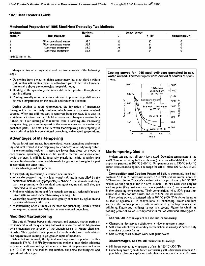
perature of certain alloy, cast. tool, and stainless steels. Cooling is delq,ed martcnsitic. and is unvmperrd and brittle. just above martensitic transformation for the lime needed to eyuahze Differences bet\teen conventional quenching and martempering (aka temperature throughout a part, for the purpose of minimizing distortion. marquenching) are shown in an adjoining Figure (see a and b).
Time-temperature transformation diagrams with superimposed cooling curves showing quenching and tempering. (a) Conven- Time-temperature transformation diagrams with superimposed cooling curves showing quenching and tempering. (a) Conven- tional process. (b) Mattempering. (c) Modified mat-tempering tional process. (b) Mattempering. (c) Modified mat-tempering
102 / Heat Treater’s Guide
Mechanical Properties of 1095 Steel Heat Treated by Two Methods
Specimen number Heat treatment
Eardoess, Impact enemy ERC J ft. Ibf Eloogstion(a), 40
I Water quench and temper 53.0 16 12 0 3 Water quench and temper 52.5 19 II 0 3 Martemper and temper 53.0 38 28 0 4 Martemper and temper 52.8 33 24 0
(a) In 25 mm or I in.
Marquenching of wrought steel and cast iron consists of the following steps:
l Quenching from the austenitizing temperature into a hot fluid medium (oil, molten salt. molten metal, or a fluidized particle bed) at a tempera- ture usually above the martensitic range (M, point)
l Holding in the quenching medium until the temperature throughout a part is uniform
l Cooling. usually in air, at a moderate rate to prevent large differences between temperatures on the outside and center of a section
During cooling to room temperature. the formation of martensite throughout a part is fairly uniform. which avoids excessive residual stresses. When the still-hot part is removed from the bath. it is easy to straighten or to form, and will hold its shape on subsequent cooling in a fixture, or in air cooling after removal from a forming die. Following marquenching, parts are tempered in the same manner as conventionally quenched parts. The time lapse between martempering and tempering is not so critical as it is in conventional quenching and tempering operations.
Advantages of Martempering Properties of steel treated in conventional water quenching and temper-
ing and steel treated in martempering are compared in an adjoining Table. In martempering residual stresses are lower than those developed in
conventional quenching because the greatest thermal variations come while the steel is still in its relatively plastic austenitic condition and because final transformation and thermal changes occur throughout a part at essentially the same time.
Other advantages of the process:
l Susceptibility to cracking is reduced or eliminated l When the austenitizing bath is a neutral salt and is controlled by the
addition of methane or by proprietary rectifiers to maintain its neutrality. parts are protected with a residual coating of neutral salt until they are immersed in the marquench bath
l Problems with pollution and tire hazards are greatly reduced if nitrate- nitrite salts are used. rather than marquenching oils
l Quenching severity of molten salt is greatly enhanced by agitation and by water additions to the bath
l Martempering often eliminates the need for quenching fixtures. which are required to minimize distortion in comentional quenching
Modified Martempering The only difference between this process and standard martempering is
the temperature of the quenching bath-it is below that of the his point- which increases the severity of the quench (see c in Figure cited pre- viously). This capability is important for steels with lower hardenabilitj that require faster cooling to get greater depth of hardness.
When hot oil is used, the typical martempering temperature in this instance is I75 “C (34.5 “F). By comparison, molten nitrate-nitrite salt baths with water additions and agitation are effective at temperatures as low as I75 “C (345 “F). The molten salt method has some metallurgical and operational advantages.
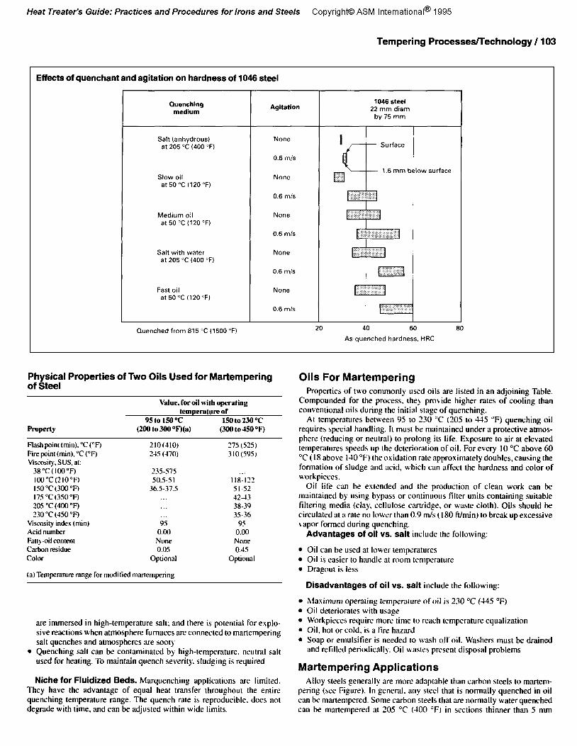
Cooling curves for 1045 steel cylinders quenched in salt, water, and oil. Thermocouples were located at centers of speci- mens.
Martempering Media Molten salt and hot oil are widely used. Operating temperature is the
most common deciding factor in choosing between salt and oil. For oil, the upper temperature is 205 “C (400 “F). Temperatures up IO 230 “C (445 “F) are an occasional exception. The range for salt is 160 to 400 “C (320 to 750 “F).
Composition and Cooling Power of Salt. A commonly used salt contains SO to 60% potassium nitrate, 37 to 50% sodium nitrite, and 0 to IO%, sodium nitrate. This salt’s melting point is approximately I40 “C (285 “F); its working range is I65 to 540 “C (330 to 1000 “F). Salts with a higher melting point (they cost less than the one just described) can be used to get higher operating temperatures. Their composition: 40 to SO8 potassium nitrate. 0 to 30% sodium nitrite, and 20 to 60% sodium nitrate.
The cooling power of agitated salt at 205 “C (400 “F) is about the same as that of agitated oil in conventional oil quenching. Water additions increase the cooling power of salt. as indicated by cooling curves in an adjoining Figure and hardness values in a second Figure, in which the cooling power of water is compared with that of water and three types of oil.
Salt VS. Oil. Advantages of salt include the following:
l Changes in viscosity are slight over a wide temperature range l Salt retains its chermcal stability. Replenishment. usually, is needed only
to replace dragout losses l Salt is easily washed from work u ith plain water
Disadvantages, salt vs. oil include the following:
l Minimum operating temperature of salt is 160 “C (320 “F) l Quenching from cyanide-based carburizing salt is hazardous because of
possible explosion: explosion and splatter can occur if wet or oily parts
Tempering Processes/Technology / 103
Effects of quenchant and agitation on hardness of 1046 steel
Physical Properties of Two Oils Used for Martempering of Steel
Oils For Martempering
Value, for oil with operating temperafurebf
95 to ISO~C 150 to 230 T (200 to 300 T)(a) (300 to 45oT)
f%shpoin~(min).“C(“F) Fire pcin~ (min). “C (“F) Vwosity. SUS, at:
38”C(IOO°F) loo”C(210°~ 150”C(300”R 17s”c(3so”F) 20.5 “C (400 OF) 230 “C (-IS0 “I3
Viscosity index (min) Acid number Faq -oil coment C&on residue Color
210~110) 2-u f-170)
175 (525) 310(59S)
23S-575 SOS-S I
36.5-37.5 118-122 5 I-52 -12-13 38-39 35-36
95 0.00
None 0.45
Optional
Properties of two commonly used oils are listed in an adjoining Table. Compounded for the process, they provide higher rates of cooling than conventional oils during the initial stage of quenching.
At temperatures between 95 to 230 “C (205 to 445 “F) quenching oil requires special handling. It must be maintained under a protective atmos- phere (reducing or neutralj to prolong its life. Exposure to air at elevated temperatures speeds up the deterioration of oil. For every IO “C above 60 “C i I8 above I30 “F) the oxidation rate approximately doubles, causing the formation of sludge and acid, which can affect the hardness and color of workpieces.
9s 0.00 None 0.05
Optional
(a)Temperature range for moctitied martempering
are immersed in high-temperature salt; and there is potential for explo- sive reactions when atmosphere furnaces are connected to martempering salt quenches and atmospheres are sooty
l Quenching salt can be contaminated by high-temperature. neutral salt used for heating. To maintain quench severity. sludging is required
l hlaximum operating temperature of oil is 230 “C (445 “F) l Oil deteriorates with usage l Workpieces require more time to reach temperature equalization l Oil, hot or cold, is a fire hazard l Soap or emulsifier is needed to wash off oil. Washers must be drained
and refilled periodically. Oil wastes present disposal problems
Martempering Applications
Niche for Fluidized Beds. Marquenching applications are limited. Alloy steels generally are more adaptable than carbon steels to martem- They have the advantage of equal heat transfer throughout the entire pcring (see Figure). In general. any steel that is normally quenched in oil quenching temperature range. The quench rate is reproducible. does not can be martempered. Some carbon steels that are normally water quenched degrade with time, and can be adjusted within wide limits. can be mat-tempered at 205 “C (100 “F) in sections thinner than 5 mm
Oil life can be extended and the production of clean work can be maintained by using bypass or continuous filter units containing suitable tiltering media (clay, cellulose cartridge. or waste cloth). Oils should be circulated at a rate no lower than 0.9 m/s ( I80 ft/min) to break up excessive vapor formed during quenching.
Advantages of oil vs. salt include the following:
l Oil can be used at lower temperatures l Oil is easier to handle at room temperature l Dragout is less
Disadvantages of oil vs. salt include the following:
104 / Heat Treater’s Guide
(0.1875 in.), using vigorous agitation of the martempering medium. In addition, thousands of flay cast iron parts are martempered on a routine hasis.
The grades of steel that are commonly martempered to full hardness include 1090.3130. ~l3O,-llSO. -1340. 300M (-!3AOhIj. -MO, 5 I-IO. 6150. 8630.86-H~. 8710. 8715. SAE I I-I I, and SAE 52 100. Carburizing Fades such as 33 I2.163O.S 120.8620, and 93 IO also are commonly martempered after carhurizing. Occasionally, higher-alloy steels such as type -l IO stain- less are martempered. but this is not a common practice.
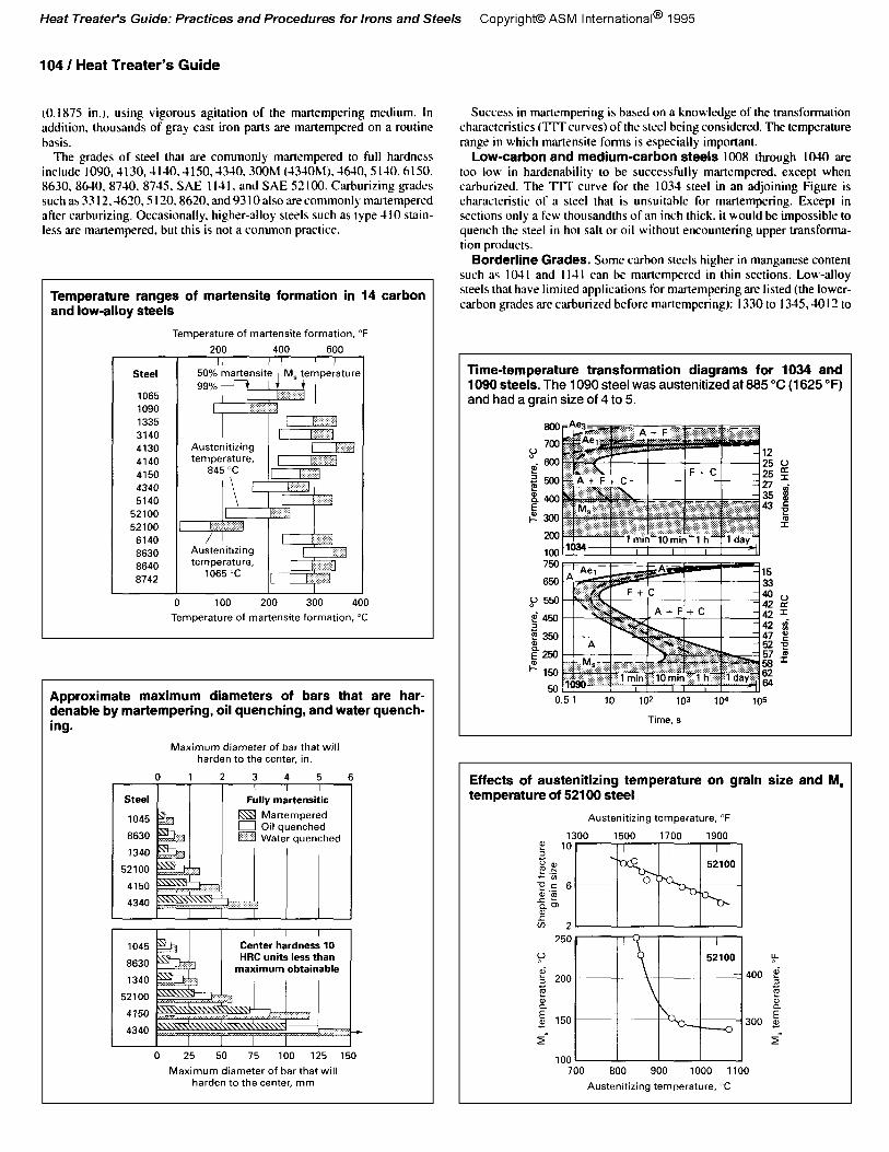
Temperature ranges of martensite formation in 14 carbon and low-alloy steels
Approximate maximum diameters of bars that are har- denable by martempering, oil quenching, and water quench- ing.
Success in martempering is based on a knowledge of the transformation characteristics (TlTcurvesj of the steel being considered. The tempe.rature range in which martensite forms is especially important.
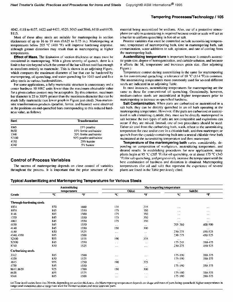
Low-carbon and medium-carbon steels 1008 through 1040 are too low in hardenability to be successfully martempered, except when carhurized. The IIT curve for the 1034 steel in an adjoining Figure is characteristic of a steel that is unsuitahle for martempering. Except in sections only a Few thousandths of an inch thick. it would be impossible to quench the steel in hot salt or oil without encountering upper transforma- tion products.
Borderline Grades. Some carbon steels higher in manganese content such a< lo-11 and I I-II can be martempered in thin sections. Low-alloy steels that have limited applications for martempering are listed (the lower- carbon grades are carburired before martempering): 1330 to I315.4017- to
Time-temperature transformation diagrams for 1034 and 1090 steels. The 1090 steel was austenitized at 885 “C (1625 “F) and had a grain size of 4 to 5.
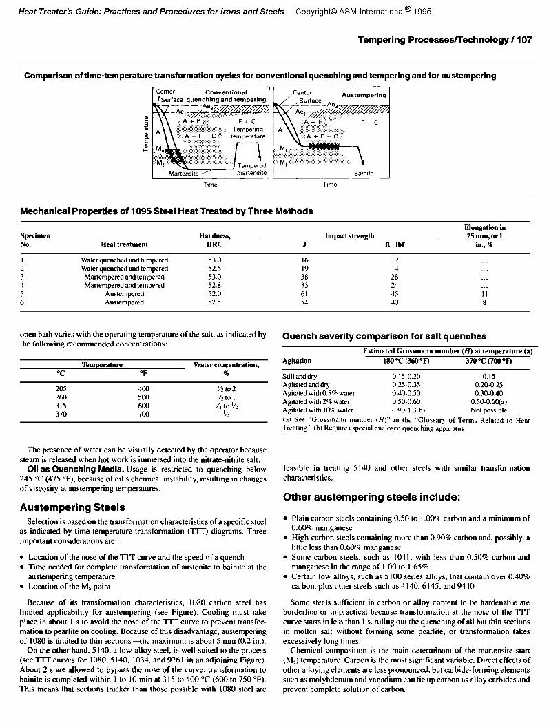
Effects of austenitizing temperature on grain size and M, temperature of 52100 steel
4032,3118to4137.~22and4~27,1520,5015and50~6,6l1Xand6120. 8115.
Most of these alloy steels are suitable for mar-tempering in section thicknesses of up to 16 to 19 mm (0.625 to 0.75 in.). Martempering at temperatures below 205 “C (-100 “F) will improve hardening response, although greater distortion may result than in mar-tempering at higher temperatures.
Effect of Mass. The limitation of section thickness or mass must be considered in mar-tempering. With a given severity of quench. there is a limit to bar size beyond which the center of the bar will not cool fast enough to transform entirely IO martensite. This is shown in an adjoining Figure. which compares the maximum diameter of bar that can be hardened by martempering, oil quenching, and water quenching for IO-t.5 steel and five alloy steels in various hardenabilities.
For some applications, a fully martensitic structure is unnecessary and a center hardness IO HRC units lower than the maximum obtainable value for a given carbon content may be acceptable. By this criterion, maximum bar diameter is 25 to 300%, greater than the maximum diameter that can be made fully martensitic (see lower graph in Figure just cited). Non-marten- sitic transformation products (pearlite. ferrite, and bainite) were observed at the positions on end-quenched bars corresponding to this reduced hard- ness value, as follows:
Steel ~ansformation
1045 159, pearlire 8630 IO% ferrite and hainite 1340 20% ferrite and hainite 52100 SOCr pearlitemd btinirr 4150 20% binite 1340 SQ binitc
Control of Process Variables The success of martempering depends on close control of variables
throughout the process. It is important that the prior structure of the
Tempering Processes/Technology / 105
material being austenitized be uniform. Also, use of a protective atmos- phere (or salt) in austenitizing is required because oxide or scale will act as a barrier to unifomr quenching in hot oil or salt.
Process variables that must be controlled include austenitizing tempera- ture. temperature of martempering bath, time in mar-tempering bath, salt contamination. \vater additions to salt, agitation, and rate of cooling from the martempering bath.
Austenitizing temperature is important because it controls austeni- tic grain size. degree of homogenization, and carbide solution, and because it affects the M, temperature and increases grain size. (See adjoining Figure.)
Temperature control during austenitizing is the same for mar-tempering as for conventional quenching: a tolerance of f8 “C (+I4 “F) is common. The austenitizing temperatures most commonly used for several different steels are indicated in an adjoining Table.
In most instances, austenitizinp temperatures for martempering are the same as those for conventional oil quenching. Occasionally, however, medium-carbon steels are austcnitized at higher temperatures prior to martempering to increase as-quenched hardness.
Salt Contamination. When parts are carburized or austenitized in a salt bath, they can be directly quenched in an oil bath operating at the martempering temperature. However. if the parts are carburized or austeni- tized in salt containing cyanide. they must nor be directly mar-tempered in salt because the two types of salts are not compatible and explosions can occur if they are mixed. Instead, one of two procedures should be used: Either air cool from the carburizing bath. wash. reheat to the austenitizing temperature for case and/or core in a chloride bath, and then martemper; or quench from the cyanide-containing bath into a neutral chloride rinse bath maintained at the austenitizing temperature and then martemper.
Temperature of the mat-tempering bath varies considerably, de- pending on composition of workpieces, austenitizing temperature, and desired results. In establishing procedures for new applications. many plants begin at 95 “C (205 “F) for oil quenching, or at about 175 “C (3-15 “F) for salt quenching, and progressively increase the temperature until the best combination of hardness and distortion is obtained. Mar-tempering temperatures (for oil and salt) that represent the experience of several plants are listed in the Tab12 pre\ iously cited.
Typical Austenitizing and Martempering Temperatures for Various Steels
Grade
Austenitizing Mat-tempering temperature temperature Oil(a) Salt(b)
OC OF T OF T OF
Through-hardening steels
102-l I070 II46 1330 4063 4130 -II-to -1140 4340. -1350 52100 52100 8740
Carburizing steels
3312 1320 4615 1720 8617.8620 8620 9310
(a) Trme in oil varies from 1 to 20 min. depending on section thi&nrss. tb) hlutempttnng temperature dcpads on shape and ma>) of part, king quenched: higher temperatures in range (and sometimes aho\c range) are used for thinner sections and more intrtcate parts.
106 / Heat Treater’s Guide
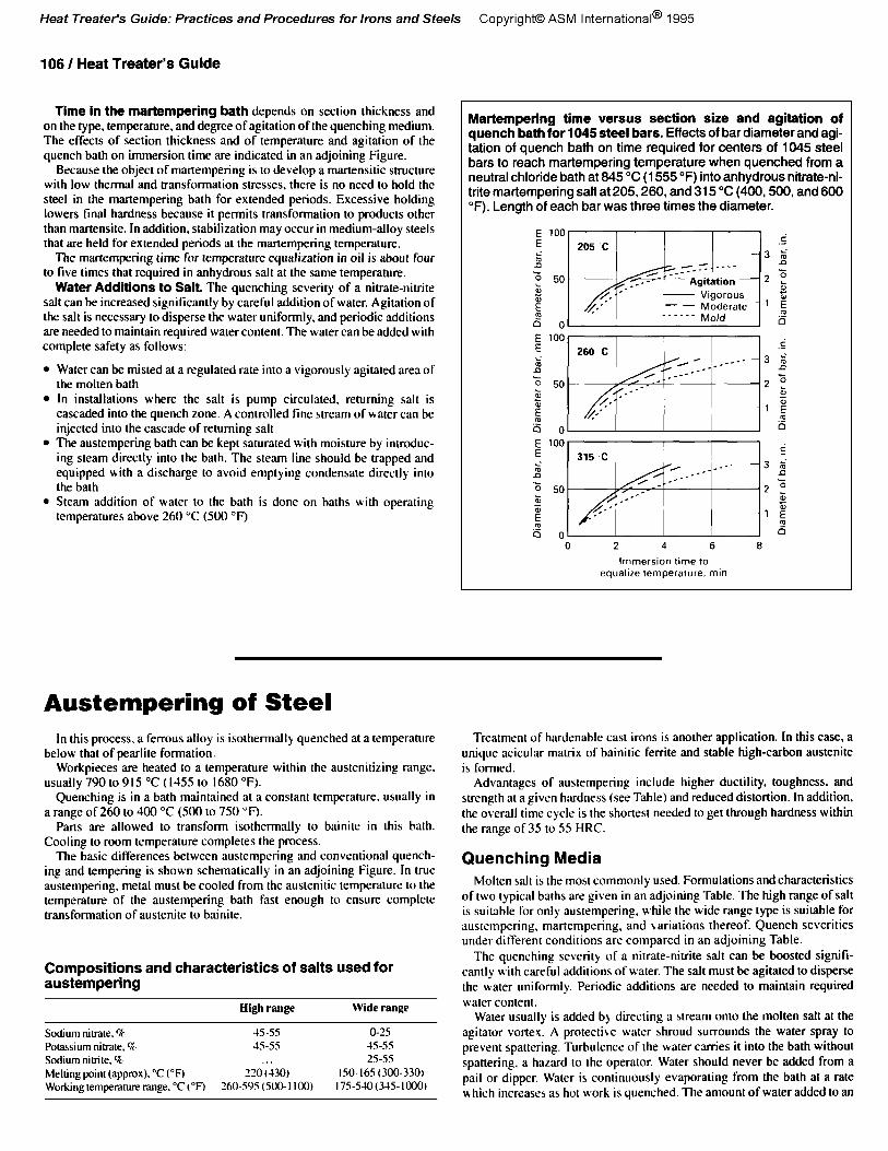
Time in the martempering bath depends on section thickness and on the type, temperature. and degree of agitation of the quenching medium. The effects of section thickness and of temperature and agitation of the quench bath on immersion time are indicated in an adjoining Figure.
Because the object of martempering is to develop a martensitic structure with low thermal and transformation stresses, there is no need to hold the steel in the martempering bath for extended periods. Excessive holding lowers foal hardness because it permits transformation to products other than martensite. In addition, stabilization may occur in medium-alloy steels that are held for extended periods al the martempering temperature.
The martempering time for temperature equalization in oil is about four fo five times that required in anhydrous salt at the same temperature.
Water Additions to Salt. The quenching severity of a nitrate-nitrite salt can be increased significantly by careful addition of water. Agitation of the salt is necessary to disperse the water uniformly, and periodic additions are needed to maintain required water content. The water can be added with complete safety as follows:
l Waler can be misted at a regulated rate into a vigorously agitated area of the molten bath
l In installations where the salt is pump circulated. returning salt is cascaded into the quench zone. A controlled fine stream of water can be injected into the cascade of returning salt
l The austemperinp bath can be kept saturated with moisture by introduc- ing steam directly into the bath. The steam line should be trapped and equipped with a discharge Lo avoid emptying condensate directly into the bath
l Steam addition of water to the bath is done on baths with operating temperatures above 260 “C (500 “F)
Martempering time versus section size and agitation of quench bath for 1045 steel bars. Effects of bar diameter and agi- tation of quench bath on time required for centers of 1045 steel bars to reach martempering temperature when quenched from a neutral chloride bath at 845 “C (1555 “F) into anhydrous nitrate-ni- trite martempering salt at 205,260, and 315 “C (400,500, and 600 OF). Length of each bar was three times the diameter.
Austempering of Steel In this process, a ferrous alloy is isothermally quenched at a temperature
below that of pearlite formation. Workpieces are heated 10 a temperature within the austenitizing range.
usually 790 to 915 “C (l-155 to 1680 “F). Quenching is in a bath maintained at a constant temperature. usually in
a range of 260 Lo 400 “C (500 to 750 OF). Parts are allowed to transform isothermally to bainite in this bath.
Cooling to room temperature completes the process. The basic differences between austempering and conventional quench-
ing and tempering is shown schemalically in an adjoining Figure. In true austempering. metal must be cooled from the auslenitic temperature to the temperature of the austempering bath fast enough to ensure complete transformation of austenite to bainite.
Compositions and characteristics of salts used for austempering
tlibh range Wide range
Sodium nitrate. Q G-55 O-25 Potassium nitrate. % 35-5s 15-55 Sodium nitrite, B 25-55 Melting Point (approx). “C (“F) 220 (430) 150.165(300-330, Working temperature range. “C t0F) 360-595 (500- I IO0 17s-540(315-1000,
Treatment of hardenable cast irons is another application. In this case, a unique acicular matrix of bainitic ferrite and stable high-carbon austenite is formed.
Advantages of austempering include higher ductility. toughness. and strength at a given hardness (see Table) and reduced distortion. In addition, the overall time cycle is the shortest needed to get through hardness within the range of 35 to 5S HRC.
Quenching Media Molten salt is the most commonly used. Formulations and characteristics
of two typical baths are given in an adjoining Table. The high range of salt is suitable for only austempering. while the wide range type is suitable for ausrsmpering, martempering, and variations thereof. Quench severities under different conditions are compared in an adjoining Table.
The quenching severity of a nitrate-nitrite salt can be boosted signifi- candy with careful additions of water. The salt must be agitated to disperse the water uniformly. Periodic additions are needed to maintain required water contenl.
Water usually is added bj directing a stream onto the molten salt at the agitator vortex. A protective water shroud surrounds the water spray Lo prevent spattering. Turbulence of the water carries it into the bath without spattering. a hazard to the operator. Water should never be added from a pail or dipper. Water is continuously evaporating from the bath at a rate H hich increases as hot work is quenched. The amount of waler added to an
Tempering Processes/Technology / 107
Comparison of time-temperature transformation cycles for conventional quenching and tempering and for austempering
Mechanical Properties of 1095 Steel Heat Treated by Three Methods
Specimen No. Beat treatment
HtUdllesS, HRC
Elongation In Impact strength 25 mm, or 1
J R Ibf in., %
I Water quenched and tempered 53.0 16 12 2 Waler quenched and tempered 52.5 19 1-l 3 Martempered and tempered 53.0 38 28 4 Martempered and tempered S2.8 33 2-I 5 Austempered 52.0 61 4s II 6 Austempered 52.5 5-t 40 8
open bath varies with the operating temperature of the salt, as indicated by the following recommended concentrations:
Quench severity comparison for salt quenches
Temperature Water concenh-atioo, T OF %
205 400 ‘4 to 2 260 500 ‘/z 10 I 315 600 ‘I4 10 ‘/2 370 700 ‘4
Agitation Estimated Grossmann number (IQ at temperature (a)
18o~C (36oOF) 370 Yz (7ooOF)
Still and dry 0.15-0.20 0.15 Agitated and dry 0.25-0.35 0.20-0.2s A@ated with 0.5% water 0.40-0.50 0.30-0.40 Agitated with 2% water 0.50-0.60 0.50-0.60(r) Agitated with IO%, water 090.I.?lbl Nor possible 131 Scr “Crossmann number (H)” In the “Glossar) of Terms Related to Heat Trrating.” lb, Requirrs special enclosed quenching apparatus
The presence of water can be visually detected by the operator because steam is released when hot work is immersed into the nitrate-nitrite salt.
Oil as Quenching Media. Usage is restricted to quenching below 245 “C (475 “F), because of oil’s chemical instability, resulting in changes of viscosity at austempering temperatures.
feasible in treating 5140 and other steels with similar transformation characteristics.
Other austempering steels include: Austempering Steels
Selection is based on the transformation characteristics of a specific steel as indicated by time-temperature-transformation (TIT) diagrams. Three important considerations are:
l Plain carbon steels containing 0.50 to I .OO% carbon and a minimum of 0.604 manganese
l High-carbon steels containing more than 0.90% carbon and, possibly, a little less than 0.60% manganese
l Location of the nose of the IIT curve and the speed of a quench l Time needed for complete transformation of austenite to bainite at the
austempering temperature l Location of the MS point
l Some carbon steels, such as IO-II. with less than O.SO%, carbon and manganese in the range of I .OO to I .6S%
l Certain low alloys, such as 5 IO0 series alloys, that contain over 0.40% carbon, plus other steels such as -II-u). 6145, and 9440
Because of its transformation characteristics, 1080 carbon steel has Some steels sufficient in carbon or alloy content to be hardenable are limited applicability for austempering (see Figure). Cooling must take borderline or impractical because transformation at the nose of the TIT place in about I s to avoid the nose of the TIT curve to prevent transfor- curve sms in less than I s. ruling out the quenching of all but thin sections mation to pearlite on cooling. Because of this disadvantage, austempering in molten salt witbout forming some pearlite. or transformation takes of 1080 is limited to thin sections-the maximum is about 5 mm (0.1 in.). excessively long times.
On the other hand, 5 140, a low-alloy steel. is well suited to the process (see TIT curves for 1080.5 140, 1034, and 9261 in an adjoining Figure). About 2 s are allowed to bypass the nose of the curve; transformation to bainite is completed within I to IO tin at 3 I5 to 400 “C (600 to 750 “F). This means that sections thicker than those possible with 1080 steel are
Chemical composition is the main determinant of the martensite start (Ms) temperature. Carbon is the most significant variable. Direct effects of other alloying elements are less pronounced, but carbide-forming elements such as molybdenum and vanadium can tie up carbon as alloy carbides and prevent complete solution of carbon.
108 / Heat Treater’s Guide
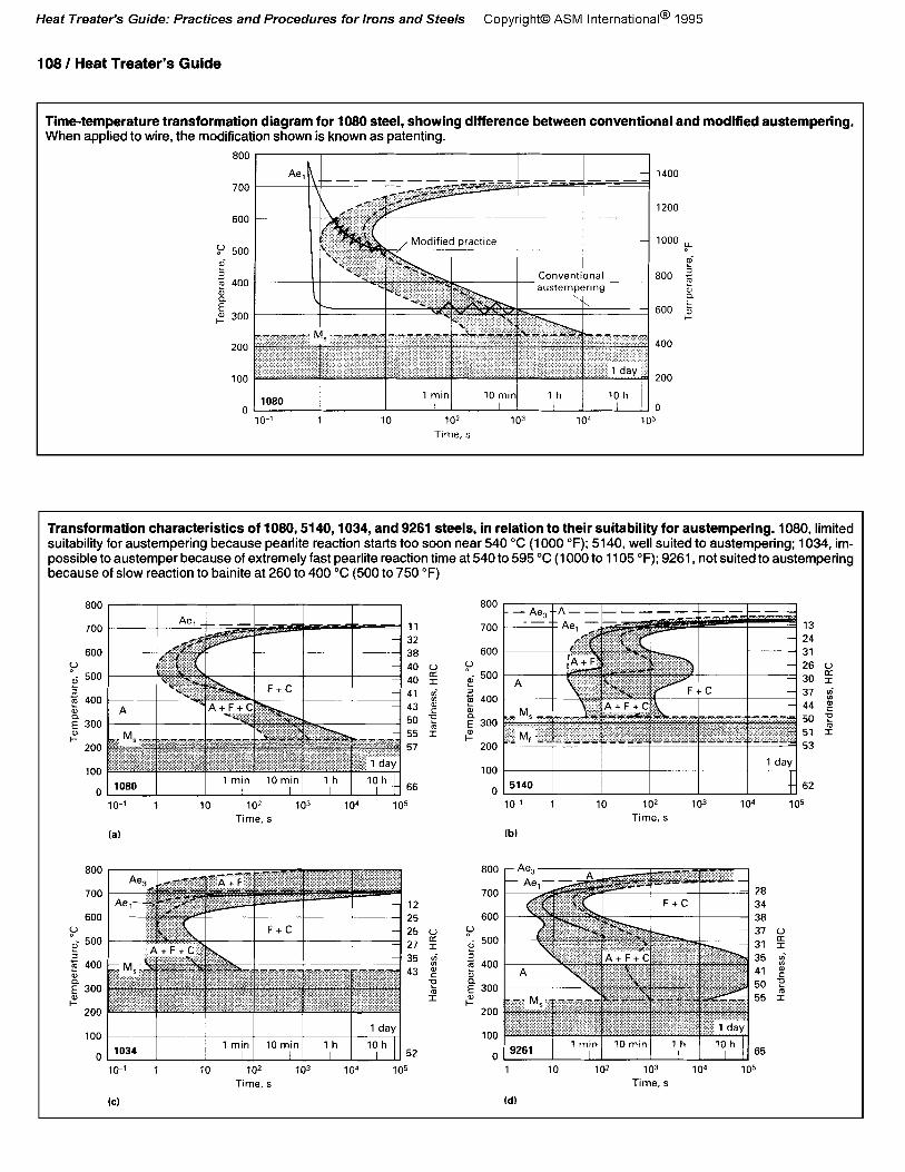
Time-temperature transformation diagram for 1080 steel, showing difference between conventional and modified austempering. When applied to wire, the modification shown is known as patenting.
Transformation characteristics of 1080,5140,1034, and 9281 steels, in relation to their suitability for austempering. 1080. limited suitability for austempering because pearlite reaction starts too soon near 540 “C (1000 “F); 5140, well suited to austempering; 1034, im- possible to austemper because of extremely fast pearlite reaction time at 540 to 595 “C (1000 to 1105 “F); 9261, not suited to austempering because of slow reaction to bainite at 260 to 400 “C (500 to 750 “F)
Tempering Processes/Technology / 109
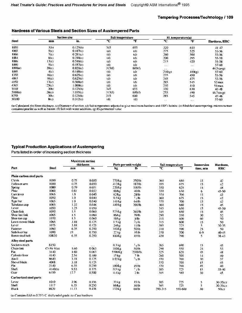
Hardness of Various Steels and Section Sizes of Austempered Parts
steel Section size Salt temperature hl, temperature(a)
mm in. T OF T OF Badness, HRC
1050 1065 IQ66 108-t 1086 lo90 1090(e) 10% 1350 4063 -tlSO 436s 5140 5160(e) 8750 so100
3(b) S(C) 7(C) wi
13(c) S(C)
20(C) YC)
16(Cl 16(C) 13(C) 25(c)
3(b) 26(C)
3(b) 8(c)
0.12% b) 0.187(C) 0 281(C) 0.218(c) 0.516(c) 0.187(c) 0.810(c) 0.118(C) 0.625~) 0.625(c) 0.500(c) I .ooo(c) 0.125(b) I .035(C) 0. IX(b) 0.312(C)
315 W (d) (di W (d) 315(f) Cd) W (d) W (di 345 315(f) 31s (d)
655 Id) (d) (d) td) (d) 600( f) (d) (d) (d) id, (db 6SS 6OOt fj 600 td)
320 610 27s 52s 260 500 200 39s 215 430
21o(gl 410(g) 235 -Iso Z-IS -17s 285 S-IS 210 110 330 630 2.55 19Q 289 51s
-tl-47 53-56 53-56 55-58 ss-58 57-60
443 (a\*@ 57-60 53-56 53-56
52 max 5-l m3.x 4348
46.7 (avg) 1748 57-60
(a~Calculnted. (b) Sheet thickness. (c) Diamelerofsection. (d) Salt temperature adjusted logi~e maximum hardness and 1005, bsinite. (el hlodlfied austempering: microsuucr~re condned pearlile as nell as binite. if) Salt with waler addilions. (g) Ehperiment3l \nlur
Typical Production Applications of Austempering Parts listed in order of increasing section thickness
Part steel
hlaximum section thiekness
mm in. Parts per unit weight kg lb
Salt temperature OC OF
Immersion time, mm
6ardlless, ERC
Plain carbon steel parts Clevis 1050 0.75 0.030 Follower arm IOSO 0.7S 0.030 Spring I080 0.79 0.03 I Plate 1060 0.81 0.032 Cam lever 106.5 I .O 0.040 Plae 1050 I .o 0.041
7)pzbu 106s IO 0.0-w Tabulator srop 106s 1.2’ 0.048 Lever I050 I.25 0 OS0 Chain link IOSO I.S 0.060 Shoe-last link 106s 1.5 0.060 Shoe-toe cap 1070 I.5 0.060 Lawn mower Made 106s 3.18 0. I IS Leter 1075 3.18 0. I25 Fastener 1060 6.35 0.250 Stabilizer bar 1090 I9 0.750 Boron steel bolt IOB20 6.35 0.250
Alloy steel parts Socket wrench 6lSO Chain link Cr-Ni-V(a) I :60 0063 Pin 3140 I60 0.063 Cylinder liner 1140 ‘5-1 0.100 Anvil 86-10 3.18 0. I25 Shovel blade 4068 3.18 0.115 Pin 3140 6.39 0.250 Shaft 111Oibj 9.53 0 37s Gecv 6150 12.7 o.sQn
Carburized steel parts Lever 1010 3.06 0.1.56 Shti III7 6.35 O.lSO Block 8620 II.13 0.438
(a1ContainsO.65 to0.7% C (b) Ladedgrade. ICI Case hardness
77Olkg IlMig 22Okg xx/kg b2kg 0.S kg I4llkg UQlkg
S72kg 86nig 18/kl. I Sb@ 7alig I I O/kg ‘? kg I-iJ/kg
0.3 kg ‘jib I IO/kg SO/lb
s500/kg 2mYlb I5 kg 7 lb
165kg ‘,, lb
I wkg 0.5 kg -I.-l kg
33 kg IS lb 664 30/Ib l3Yhg honb
187/lb IQwlh lonb ‘8nb ‘!iIh
6Mb
26011b 39nh xnh ?j I b I l/lb sonb IOlh 4vlb
4vib “, lb 2 Ih
360 3SS 330 330 370 360 370 360 345 34s 290 315 315 385 310 370 -110
365 b9O 290 550 37s 620 260 3nJ 370 700 370 700 370 700 38s 72s 305 580
38S 385
290-3 I5
680 675 625 b.10 7OO b75 700 680 650 690 SSO
Et 72s F90 700 790
72s 72s
550-600
IS -I2 IS -I’ I5 -I8 6 e-so IS -I2 IS J2 IS 1’ IS 35 IS -Is-so IS JS 30 53 60 so IS so 5 30-3s
25 so 6-9 -IO--IS 5 38-43
IS 2s -IS I-l 30 IS 15 IS 30
5 5
30
-IS s3 18 -to 37 45 30
35-40 15
30-35(C) 30-39(C)
SO(C)
110 / Heat Treater’s Guide
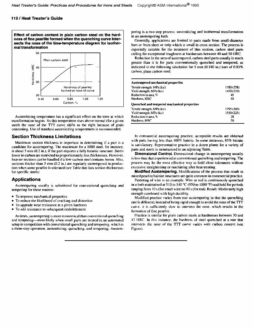
Effect of carbon content in plain carbon steel on the hard- ness of fine pearlite formed when the quenching curve inter- sects the nose of the time-temperature diagram for isother- mal transformation
Austenitizing temperature has a significant eFfect on the time at which transformation begins. As this temperature rises above normal (for a given steel) the nose of the TTT curve shifts to the right because of grain coarsening. Use of standard austenitizing temperatures is recommended.
Austempered mechanical properties Tensile strength. MPa (ksi) Keld strength. MPa (ksi) Reduction in area. %, Hardness, HRC
Quenched and tempered mechanical properties Tensile strength. MPa (ksi) Yield strength. MI% (hi ) Reduction in area. %, Hardness. HRC
1780(258) 1450(210)
45 SO
I795 (260) 1550(225)
28 SO
Section Thickness Limitations Maximum section thickness is important in determining if a part is a
candidate for austempering. The maximum for a 1080 steel, for instance, is about 5 mm (0.2 in.), if the part requires a fully bainitic structure. Steels lower in carbon are restricted to proportionately less thicknesses. However. heavier sections can be handled if a low-carbon steel contains boron. Also, sections thicker than 5 mm (0.2 in.) are regularly austempered in produc- tion when some pearlite is tolerated (see Table that lists section thicknesses for specific steels).
Applications Austempering usually is substituted for conventional quenching and
tempering for these reasons:
l To improve mechanical properties l To reduce the likelihood of cracking and distortion l To upgrade wear resistance at a given hardness l To add resistance to subsequent embrittlement
In commercial austempering practice, acceptable results are obtained with parts having less than 100% bainite. In some instances, 85% bainite is satisfactory. Representative practice in a dozen plants for a variety of parts and steels is summarized in an adjoining Table.
Dimensional Control. Dimensional change in austempering usually is less than that experienced in conventional quenching and tempering. The process may be the most effective way to hold close tolerances without excessive straightening or machining after heat treating.
Modified Austempering. hlodifications of the process that result in mixed pearlitelbainite structures are quite common in commercial practice.
Patenting of wire is an example. Wire or rod is continuously quenched in a bath maintained at 5 IO to 540 “C (950 to 1000 “F) and held forperiods ranging from IO s (for small wire) to 90 s (for rod). Result: Moderately high strength combined uith high ductility.
Modified practice varies from true austempering in that the quenching rate is different; instead of being rapid enough to avoid the nose of the TIT tune. it is sufficiently slow to intersect the nose, which results in the formation of tine pearlite.
At times. austempering is more economical than conventional quenching Practice is similar for plain carbon steels at hardnesses between 30 and
and tempering-most likely when small parts are treated in an automated 12 HRC. In this instance. the hardness of steel quenched at a rate that setup in competition with conventional quenching and tempering, which is intersects the nose of the TIT curve varies with carbon content (see a three-step operation: austenitizing. quenching, and tempering. Austem- Figure).
pering is a tbo-step process: austenitizing and isothermal transformation in an austempering bath.
Generally, applications are limited to parts made from small-diameter bars or from sheet or strip which is small in cross section. The process is especially suitable for the treatment of thin section, carbon steel parts calling for exceptional toughness at hardnesses between 40 and 50 HRC.
Reduction in the area of austempered, carbon steel parts usually is much greater than it is for parts conventionally quenched and tempered, as indicated in the following tabulation for 5 mm (0.180 in.) bars of 0.85% carbon, plain carbon steel: