template br_rec_2002.dot - itu · web viewthe operational use of two-way satellite time and...
TRANSCRIPT

Rec. ITU-R TF.1153-2 1
RECOMMENDATION ITU-R TF.1153-2
The operational use of two-way satellite time andfrequency transfer employing PN codes
(Question ITU-R 201/7)
(1995-1997-2003)
The ITU Radiocommunication Assembly,
consideringa) the potential for high-accuracy of the two-way satellite time and frequency transfer (TWSTFT) method as expressed in Question ITU-R 201/7;b) the demonstrated high performance of TWSTFT systems using telecommunication satellites in the 14/11 GHz and 14/12 GHz bands;c) that other frequency bands are becoming important;d) the demonstrated time calibration results of TWSTFT systems;e) that theoretical background is available to calculate the corrections for the effect of the propagation delay through the troposphere and the ionosphere, the correction for the Sagnac-effect, and other reciprocity factors;f) that the number of participants is increasing;g) the need for standardizing:– measuring procedures,– data processing,– format for the exchange of data and relevant information between pairs of participants,
recommends1 that the measuring and data processing procedures for accurate time and frequency transfer be followed as outlined in Annex 1;2 that the data format for the exchange of the relevant data between pairs of participants should include the information as outlined in Annex 2.
Annex 1
Procedures for TWSTFT
1 Introduction
Radio links can be used to transfer time from one clock to another. In radio links however, the signal delays are changing with distance, ionosphere, troposphere, temperature, earth conductivity and so on. To cancel these influences to first order the two-way scheme has been introduced: at both clock sites the time signals are transmitted at the same instant and on both sides the signal from the

2 Rec. ITU-R TF.1153-2
other clock is received and measured. After the exchange of the measured data, the difference of the two clocks is calculated. The delays cancel due to the complete reciprocity, to first order, of the signal paths. The accuracy of the result then depends on the residual effects due to the incomplete reciprocity. Some of these effects are known and others are still unknown. In some cases corrections for these effects can be used to improve accuracy.
The up/down difference exists due to the distance between receive and transmit antennas. There are difference paths for the up and down link if the receive and transmit antennas of the satellite are not the same. The effect depends on the altitude of the satellite at the station. The system error of the link will be changed when the satellite link is from one to another.
1153-01
TS(1)
TS(2)
TU(1) TD(1)
TCD(1)TCU(1)
TT(1) TR(1)
TI(1)
1PPSTX(1)TA(1)
TU(2)
TCU(2)
TD(2)
TCD(2)
TR(2)TT(2)
TI(2)
TA(2) 1PPSTX(2)
FIGURE 1
TWSTFT principle
Time scale(clock)
Time intervalcounter
Transmitter Receiver
Satellite
Transmitter Receiver
Time intervalcounter
Time scale(clock)
Station 1 Station 2
From Fig. 1, it can be seen how the difference of the clocks at stations 1 and 2 can be determined.TA(k): time-scale of the 1PPSTX reference point at station k, k being 1 for station 1 and 2 for
station 2TI(k): time interval readingTT(k): transmitter delay, including the modem delayTR(k): receiver delay, including the modem delayTU(k): uplink propagation delayTD(k): downlink propagation delayTS(k): satellite delayTCU(k): Sagnac correction in the uplinkTCD(k): Sagnac correction in the downlink.

Rec. IT
U-R
TF.1153-2
25
Rec. ITU-R TF.1153-2 3
The difference of the time-scale (1PPSTX) at station 2 from the time-scale (1PPSTX) at station 1 expressed by TA(1) _ TA(2) is determined as follows.
The time interval counter (TIC) reading at station 1 is:
TI(1) TA(1) – TA(2) TT(2) TU(2) TCU(2) TS(2) TD(1) TCD(1) TR(1)
The TIC reading at station 2 is:
TI(2) TA(2) – TA(1) TT(1) TU(1) TCU(1) TS(1) TD(2) TCD(2) TR(2)
Subtracting the expression of station 2 from that of station 1, gives:
TI(1) – TI(2) 2TA(1) – 2TA(2) TT(2) – TT(1) TU(2) – TU(1) TS(2) – TS(1) TD(1) – TD(2) TR(1) – TR(2) TCD(1) – TCU(1) – TCD(2) TCU(2)
The time-scale difference is given by:TA(1) – TA(2) 1/2[TI(1)] (TIC reading at station 1)
1/2[TI(2)] (TIC reading at station 2)1/2[TS(1) – TS(2)] (Satellite delay difference)1/2[TU(1) TD(1)] (Up/down difference at station 1)–1/2[TU(2) TD(2)] (Up/down difference at station 2)1/2[TT(1) TR(1)] (Transmit/receive difference at station 1)–1/2[TT(2) TR(2)] (Transmit/receive difference at station 2)1/2[TCD(1) TCU(1)] (Sagnac correction for station 1 including the
correction for satellite movement)1/2[TCD(2) TCU(2)] (Sagnac correction for station 2 including the
correction for satellite movement).
The last seven terms are the corrections for non-reciprocity. The corrections can be determined and grouped in corrections per station. Each station exchanges the TI(k) data together with the assessment of its own corrections to the other station.
The non-reciprocity factors are further addressed in the following sections.
2 Non-reciprocity due to satellite equipment delaysWhen the satellite receive antenna, transponder channel and transmit antenna are common to both signal paths, the satellite signal delays are equal, i.e. TS(1) TS(2).This is not the case when different frequencies, transponders or different spot beams are used for the reception and/or transmissions from each station, e.g. the transatlantic Intelsat satellites. In this case TS(1) and TS(2) or at least the difference TS(1) TS(2) should be measured before the launch of the satellite or using another accurate time transfer method.
3 Sagnac-effect correction
Due to the movement around the rotation axis of the Earth, both of the earth stations and of the satellite during the propagation of a time signal to and from the satellite, a correction has to be applied to the propagation time of the signal. The Sagnac correction for the one-way path from satellite s to ground k is given by:
TCD(k) ( / c2) [Y(k) X(s) – X(k) Y(s)]

4 Rec. ITU-R TF.1153-2
where: : Earth rotation rate 7.2921 10–5 rad/sc : speed of light 299 792 458 m/s
X(k) : geocentric x-coordinate of station (m) r cos[LA(k)] cos[LO(k)]
X(s) : geocentric x-coordinate of satellite (m) R cos[LA(s)] cos[LO(s)]
Y(k) : geocentric y-coordinate of station (m) r cos[LA(k)] sin[LO(k)]
Y(s) : geocentric y-coordinate of satellite (m) R cos[LA(s)] sin[LO(s)]r : Earth radius 6 378 140 mR : satellite orbit radius 42 164 000 m
LA : latitudeLO : longitude.
For geostationary satellites LA(s) 0, so TCD(k) ( / c2) R r cos[LA(k)] sin[LO(k) – LO(s)].
Total Sagnac correction TC(12) for clock at station 1 as reference to measure clock at station 2 is:
TC(12) 1/2(TCU(1) TCD(2) – [TCU(2) TCD(1)])Further, the sign of the Sagnac correction for the downlink is opposite to the sign of the Sagnac correction for the uplink due to the opposite directions of the signals: TCU(k) –TCD(k), so TC(12) –TCD(1) TCD(2).
Example for a satellite at 307 E:LA(VSL) 52 N, LO(VSL) 4 E, LO(sat) 307 E, difference in LO 57, TCD(VSL) 112.42 nsLA(USNO) 39 N, LO(USNO) 283 E, LO(sat) 307 E, difference in LO –24, TCD(USNO) – 68.83 nsTC(VSLUSNO): –TCD(VSL) TCD(USNO) –181.25 nsTC(USNOVSL): –TCD(USNO) TCD(VSL) 181.25 nsVSL: NMi Van Swinden Laboratory, Delft, the NetherlandsUSNO: US Naval Observatory, Washington DC, United States of America.
4 Non-reciprocity effects due to satellite movement in an earth fixed frameTwo-way paths between earth stations via the satellite are not reciprocal if the satellite is in motion relative to the Earth’s surface and if the two arriving signals do not pass through the satellite at the same instant. This effect may be compensated for by a slight adjustment (17 ms) of emission times. If synchronization errors are not compensated for in this way, the error itself, which may be of the order of 1 ns, requires correction.

Rec. IT
U-R
TF.1153-2
25
Rec. ITU-R TF.1153-2 5
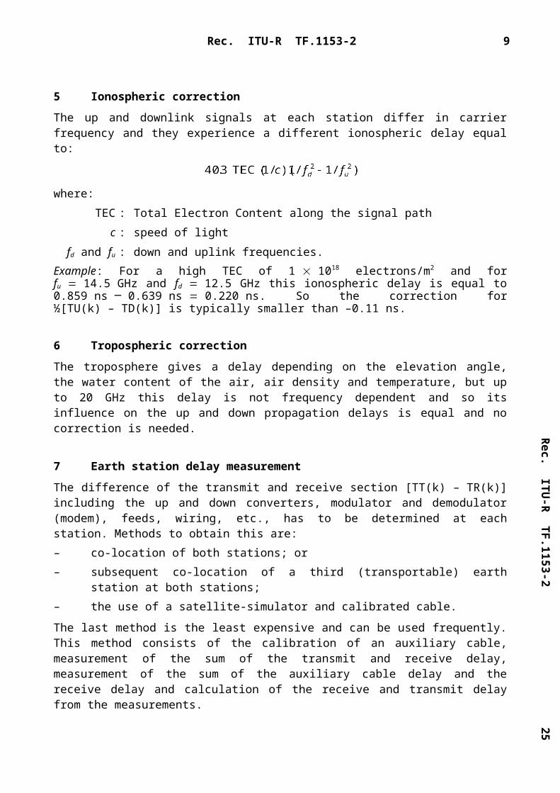
5 Ionospheric correction
The up and downlink signals at each station differ in carrier frequency and they experience a different ionospheric delay equal to:
where:TEC : Total Electron Content along the signal path
c : speed of lightfd and fu : down and uplink frequencies.
Example: For a high TEC of 1 1018 electrons/m2 and for fu 14.5 GHz and fd 12.5 GHz this ionospheric delay is equal to 0.859 ns _ 0.639 ns 0.220 ns. So the correction for ½[TU(k) – TD(k)] is typically smaller than –0.11 ns.
6 Tropospheric correction
The troposphere gives a delay depending on the elevation angle, the water content of the air, air density and temperature, but up to 20 GHz this delay is not frequency dependent and so its influence on the up and down propagation delays is equal and no correction is needed.
7 Earth station delay measurement
The difference of the transmit and receive section [TT(k) – TR(k)] including the up and down converters, modulator and demodulator (modem), feeds, wiring, etc., has to be determined at each station. Methods to obtain this are:– co-location of both stations; or– subsequent co-location of a third (transportable) earth station at both stations;– the use of a satellite-simulator and calibrated cable.
The last method is the least expensive and can be used frequently. This method consists of the calibration of an auxiliary cable, measurement of the sum of the transmit and receive delay, measurement of the sum of the auxiliary cable delay and the receive delay and calculation of the receive and transmit delay from the measurements.
The internal transmit and receive delay difference of the modem have to be determined as well. This can be done by:– co-locating the modems and measuring the sum of the transmit delay of one modem and the
receive delay of the other;– by measuring the sum of transmit and receive delay by connecting the IF output signal to
the IF input of each of the modems. The transmit delay between the 1 pps transmitted and the appropriate phase reversal in the IF phase modulated output signal of the modem is measured, e.g. by an oscilloscope. The receive delay is found by subtracting the transmit delay from the measured sum of the delays.

6 Rec. ITU-R TF.1153-2
8 Data processing
In order to determine the difference between the UTC(k) of the two participating laboratories, one must carefully measure and document the delays which occur in the timing chain of each laboratory. In some laboratories, UTC(k) is a mathematical time-scale. All laboratories have a master clock (clock(k)) which is the physical representation of this time-scale. Each laboratory computes a table of values with the relationship of its master clock to its time-scale [UTC(k) – clock(k)]. Clock(k) can be used as input ref(k) to the modem which generates the PN code which is transmitted. There is a delay [clock(k) – ref(k)] caused by the cabling associated with connecting clock(k) to the modem. The modem generates a 1PPSTX which is related to the transmitted signal which allows the difference [ref(k) _ 1PPSTX(k)] with respect to the ref(k) to be measured.
To calculate the difference between the UTC time scales of the two laboratories from[TA(1) – TA(2)] (see § 1), the following applies:
UTC(1) – UTC(2) TA(1) – TA(2)– [UTC(1) – clock(1)]– [clock(1) – ref(1)]– [ref(1) – 1PPSTX(1)] [UTC(2) – clock(2)] [clock(2) – ref(2)] [ref(2) – 1PPSTX(2)]
9 Determination of accuracy and stability of the result
The general guidelines of the International Organization for Standardization (ISO) (1993) “Guide to the expression of uncertainty in measurement” should be followed along with the characterization of performance procedures outlined in Recommendation ITU-R TF.538.
10 Performance characteristics of the earth station
There are two levels of earth station performance and operation that must be considered for two-way time transfers. The first level concerns meeting the basic requirements of the modem to produce the desired output phase jitter. The second level concerns the performance characteristics of the earth station as required by the regulatory organizations.
Meeting regulatory requirements do not by themselves guarantee satisfactory two-way operation. Only when the required C / N0 and carrier level C is delivered to the modem will one get satisfactory results. Operating parameters are determined from a link budget. From the link budget, one can determine the size of antenna required, the transmit power required and the required noise temperature of the receive system. The link budget may be calculated following the direction and examples given in § 2.3, Chapter 2 and § AN2.1, Annex 2 of the ITU Handbook on Satellite Communications (third edition, Geneva, 2002).

Rec. IT
U-R
TF.1153-2
25
Rec. ITU-R TF.1153-2 7
Regulatory requirements usually originate with the administrative bodies responsible for the general management of the electromagnetic spectrum at national and international level and with the satellite operator. The rules and regulations often dictate when and where an earth station may be erected, the quality of that earth station, and its ownership and operation. These rules and regulations usually are intended to guarantee that the earth station will not generate interference to other earth stations and to other adjacent satellites. Issues involved usually include antenna patterns and antenna gain, G / T, e.i.r.p., polarization discrimination criteria, and the training and licensing of operating staff. Much of the technical matter concerned with the earth station can be guaranteed by the procurement of systems from manufacturers who have already qualified the equipment for operation with specific satellite systems and standards.
Electrical performance standards are usually defined by one or more of the following: Recommendations ITU-R S.580 and ITU-R S.465; US FCC regulation 25-209 from the Code of Federal Regulations, Title 47, Parts 20-39; and INTELSAT Earth Station Standard documents for standard C (IESS-203), standard E (IESS-205), standard G (IESS-601), and standard Z (IESS-602) earth stations. Some regions of the world may have other requirements relating to the satellite system, location, classification of user, and other criteria.
Annex 2
Information on the data format for data exchange
1 Introduction
The data file begins with a header which should contain all data that are not considered to change during the measurement session. The subsequent data lines contain all data that are expected to change during the session. Some data lines contain information for experimental purposes (e.g. the once-per-second readings) whereas other data lines contain information directly for operational use (e.g. the quadratic “best fit” for a session). At present there exist more than one type of modem for TWSTFT and two types of data measurement reported. One of them is that each station reports its own measured results, and the other is that one of the participating station reports in real time the final time transfer results obtained by combining the data measured at both stations. In this Annex, we denote § 3.2.1 “Type 1 – Individual measurements” for the former case and § 3.2.2 “Type 2 – Combined measurements” for the latter one.
2 Required information
2.1 Station identification and assigned characters, codes and offset-frequencies
The identification of the participating stations by an ASCII character should be done, and PN codes and a clean carrier offset frequency should be assigned.
As an example, see Table 1.

8 Rec. ITU-R TF.1153-2
TABLE 1
2.2 Session parameters
A plan for a session should contain the following information:– satellite identification: name, longitude, orbital parameters, transponder channel, satellite
equipment non-reciprocity;– station designations; – TX-codes and RX-codes;– link budget;– earth station TX and RX frequencies;– operator's name;– start date and time;– preparation time for each session (equal to the pause between successive sessions);– duration of each session;– the way to exchange the generated data files.
2.3 Local earth station(k) parameters
Each station should keep on file the following information:– antenna coordinates (x, y, z in the IERS terrestrial reference frame);– earth station designator;
MITREX modem
Laboratorydesignation
(ASCII character)TX code
Clean carrier offset(kHz from
centre frequency)
A 0 – 20B 1 0C 2 20D 3 – 40E 4 40F 5 60G 6 80H 7 – 80
ATLANTIS modem
Laboratory designation TX code
Clean carrier offset(kHz from
centre frequency)
Local 2 089 0Remote 3 232 0
Rec. IT
U-R
TF.1153-2
25
Rec. ITU-R TF.1153-2 9
– transmit power e.i.r.p. (W);– G / T of the receiver;– modem: manufacturer, model, type, serial number;– time interval counter: manufacturer, type, serial number;– antenna: manufacturer, type, diameter, gain;– delay calibration: date, method, results;– optional: record during the sessions the measured TX-RX delay, the C / N0, the
environmental parameters at the antenna (temperature, humidity, barometric pressure, weather conditions).
Any change in station parameters and equipment should be reported.
3 Data format
3.1 GeneralThe conventions and symbols reported below apply completely to the data format described in § 3.2 and partly to that in § 3.3.LAB: laboratory identification (e.g., according to the Bureau international des poids et mesures
(BIPM) convention)jjjjj: modified Julian dayhh: UTC hourmm: UTC minutess: UTC secondL: designation of Local laboratory by an ASCII characterR: designation of Remote laboratory by an ASCII character*: indication of the start of a line of textS: indication of the sign of the subsequent value[ ]: designation of an option|: designation of a choice0.nnnnnnnnnnnn: value of a time interval (s) (12 decimals 1 ps resolution).
DATA FILE NAME:
Ljjjjjhh.mmRwhere jjjjj, hh, mm give the NOMINAL start date of the TWSTFT session.
HEADER:* Ljjjjjhh.mmR* UTC (LAB) – CLOCK S0.nnnnnnnnnnnn [jjjjj hhmmss]* CLOCK – 1PPSREF S0.nnnnnnnnnnnn [jjjjj hhmmss]* 1PPSREF – 1PPSTX S0.nnnnnnnnnnnn [jjjjj hhmmss]* Any other parameter of the form: PARAMETER Value [units] [jjjjj hhmmss]* DATA [1PPSTX – 1PPSRX] | [1PPSREF – 1PPSRX] | [..]where jjjjj, hhmmss optionally give the date at which the indicated value is taken.

10 Rec. ITU-R TF.1153-2
3.2 Report of the individual 1 s measurements
3.2.1 Type 1 – Individual measurementsDATA FILE FORMAT:the HEADER immediately followed by the DATA.
DATA:jjjjj hhmmss 0.nnnnnnnnnnnnjjjjj hhmmss 0.nnnnnnnnnnnn
jjjjj hhmmss 0.nnnnnnnnnnnn
where jjjjj, hhmmss give the date at which the data is taken.
EXAMPLE:File A4926610.56B (data measured at station A from a TWSTFT session with station B on MJD 49266, scheduled at 1056 h UTC):
* A4926610.56B* UTC (LAB A) – CLOCK – 0.000000123456 49266 101000* CLOCK – 1PPSREF 0.000000012345* 1PPSREF – 1PPSTX 0.000000001234 49266 102059* DATA 1PPSTX – 1PPSRX49266 105616 0.27092466640649266 105617 0.27092466380549266 105618 0.27092466017049266 105619 0.27092465762849266 105620 0.27092465427049266 105621 0.270924651106
3.2.2 Type 2 – Combined measurements
None.
3.3 File format reporting results of a quadratic fit
3.3.1 General remarks
The purpose of this format is to reduce the amount of data to be exchanged and to be able to report in one data file tracks of one laboratory involving different partner stations and different satellite links. Data of more than one day may be reported in one file. It allows clock differences to be calculated in an easy way, using the information given in the header and data lines, without having to know individual measurement set-ups at the participating laboratories.
There are two kinds of lines:– lines with an asterisk in column one (file header, data line header);– lines without an asterisk in column one (data lines).In the format description, characters in bold letters are keywords at a certain position, characters in cursive letters have to be replaced by actual strings or values, respectively. Strings in brackets are optional, and whenever data must be preceded by a sign, it is indicated by a “”. Any missing data should be replaced by series of 9 (including a possible sign).

Rec. IT
U-R
TF.1153-2
25
Rec. ITU-R TF.1153-2 11
3.3.2 File name
3.3.2.1 Type 1 – Individual measurements
The file name consists of TW (for two-way satellite time and frequency transfer), the designation of the laboratory (LLLL, up to four characters according to the acronyms of the laboratories as given in the Annual Report of the BIPM Time Section) and the Modified Julian Day as given in the first data line (the last three digits as file extension): TWLLLLMM.MMM (for example TWTUG50.091).
3.3.2.2 Type 2 – Combined measurements
The file name consists of TW (for two-way satellite time and frequency transfer), the designation of the region of the laboratory pair (LLLL, up to four characters) and the Modified Julian Day as given in the first data line (the last three digits as file extension): TWLLLLMM.MMM (for example TWAP52.520).
3.3.3 Header
Number of columns in header lines are limited to 78..........1.........2.........3.........4.........5.........6.........7........123456789012345678901234567890123456789012345678901234567890123456789012345678
* TWLLLLMM.MMM* FORMAT nn* LAB LLLL* REV DATE YYYY-MM-DD* ES LLLLnn LA: D dd mm ss.sss LO: D ddd mm ss.sss HT: +nnnn.nn m* REF-FRAME RRRRRRRRRR* LINK LL SAT: SSSSSSSSSSSSSSSSSS NLO: D ddd mm ss.sss XPNDR: +nnnn.nnn ns
* SAT-NTX: fffff.ffff MHz SAT-NRX: fffff.ffff MHz
* CAL CCC TYPE: TTTTTTTTTTTTTTTTT MJD: MMMMM EST. UNCERT.: nnnn.nnn ns* LOC-MON [YES] [NO]* MODEM TYPE, SERIAL NUMBER* COMMENTS SSSSSSSSSSSSSSSSSSSSSSSSSSSSSSSSSSSSSSSSSSSSSSSSSSSSSSSSSSSSSSSSSS
*
TWLLLLMM.MMM File name (see § 3.3.2)
FORMAT Format version (from 01 to 99).
LAB Acronym of the laboratory where the observations are performed. For the acronyms of the laboratories see the Annual Report of the BIPM Time Section.
REV DATE Revision date of the header data, changed when one parameter given in the header is changed apart from the file name. Each file of one laboratory has to have a unique file name and different files may have the same header. YYYY-MM-DD for year, month and day.
ES Name and position of earth station:
LLLLnn Name of earth station formed of the laboratory's acronym (up to four characters) and a station identification number (two digits), for example TUG01.
LA Latitude in geodetic coordinates, replacing D by N (North) or S (South).

12 Rec. ITU-R TF.1153-2
LO Longitude in geodetic coordinates, replacing D by W (West) or E (East).
HT Height (m).
One line describes one earth station, but as many ES lines as necessary can be used.
REF-FRAME Designation of the reference frame of the two-way antenna coordinates. As many columns as necessary:
LINK LINK lines characterize the satellite links.
LL Link identification contained in each data line (data line header: LI, see § 3.3.4), which points to a specific LINK line of the file header.
SAT Satellite identification according to designation of satellite operating agency or international space community.
NLO Nominal longitude of satellite, replacing D by W (West) or E (East).
XPNDR Differential transponder delay (ns) (local station to remote station minus remote station to local station).
SAT-NTX Nominal transmit frequency of satellite (MHz). This frequency corresponds to the receive frequency of the local earth station.
SAT-NRX Nominal receive frequency of satellite (MHz). This frequency corresponds to the transmit frequency of the local earth station.
Two lines describe one link, but as many couples of LINK lines as necessary can be used.
CAL CAL lines give the calibration type, the Modified Julian Day and the estimated uncertainty of the calibration:
CCC Calibration identification contained in each data line (data line header: CI, see § 3.3.4), which points to a specific CAL line of the file header.
TYPE Type of technique used for a certain link characterized by one of the following key words:
PORT ES REL Portable earth station used in a relative mode.
PORT ES ABS Portable earth station used in an absolute mode.
PORT SS REL Portable satellite simulator used in a relative mode.
PORT SS ABS Portable satellite simulator used in an absolute mode.
Calibration by an independent time transfer system, for example:
GPS Global Positioning System.
PORT CLOCK Portable clock.
Different types may be used for the same link resulting in different data lines.
MJD Modified Julian Day of the calibration.
EST.UNCERT. Estimated uncertainty of the calibration.

Rec. IT
U-R
TF.1153-2
25
Rec. ITU-R TF.1153-2 13
A calibration is described in one line, but as many CAL lines as necessary can be used.
LOC-MON YES or NO has to be used depending on the availability of a local earth station delay monitoring system.
MODEM Type and serial number of modem used. All modems used during the period of validity of the file should be reported.
As many lines and columns as necessary can be used.
COMMENTS Comment lines as many as necessary.
The last line of the file header contains an asterisk at column 1 only.
3.3.4 Data line
3.3.4.1 Type 1 – Individual measurements
For the format of a data line see Appendix 1 to Annex 2.
EARTH-STAT Designation of local (LOC) and remote (REM) earth station given by the respective laboratory’s acronym (up to four characters) and a station identification number (two digits), for example TUG01.
LI Link identification is a pointer to the file header that gives information on a specific satellite link.
The assignment of link identifications has to be coordinated on an international basis such as by the CCTF Working Group on Two-Way Satellite Time and Frequency Transfer (for examples see § 3.3.6.1).
MJD STTIME Nominal start date (MJD and time (h, min, s), referenced to UTC).
NTL Nominal track length (s) (nominal date of last sample minus nominal date of first sample).
TW Result (s), of a quadratic fit over the data of one track calculated for the date given by the nominal start date plus half of the nominal track length rounded to seconds.
DRMS Root mean square of the residuals to the quadratic fit (ns).
SMP Number of samples used in the quadratic fit.
ATL Actual track length (s) (date of last sample minus date of first sample of the quadratic fit).
REFDELAY Delay of the reference with respect to UTC(LAB) (s). The calculation of this term depends on the measurement set-up at each laboratory. For the usually employed measurement set-up (PPSTX starts two-way measurements) the reference delay is the sum (UTC(LAB)-CLOCK) (CLOCK-REF) (REF-PPSTX).
RSIG Standard deviation of the mean of REFDELAY (ns).
CI Calibration identification is a pointer to the file header, which informs about the calibration type, the Modified Julian Day and the estimated uncertainty of the calibration.

14 Rec. ITU-R TF.1153-2
The assignment of a calibration identification has to be coordinated on an international basis (such as by the CCTF Working Group on Two-Way Satellite Time and Frequency Transfer) for the laboratories involved in a specific calibration campaign. Using an independent time transfer system (e.g. GPS) calibrations are only possible between pairs of laboratories, therefore calibration identifications have to be assigned for pairs of laboratories (for examples see § 3.3.6.1).
S Calibration switch (either “0” or “1”). It indicates which terms of the two-way equation are included in the calibration result CALR and which equation must therefore be used for the computation of the clock differences (see § 3.3.5.1).
S 0 The calibration result CALR gives the difference between the differential earth station delay (transmit part minus receive part) of the laboratory and the differential earth station delay of the calibrating system (collocation of earth stations, satellite simulator).
S 1 The calibration result CALR includes all terms of the two-way equation except the time transfer measurements TW and the reference measurements REFDELAY of the local and remote station, respectively. This is the case using an independent time transfer system, e.g. GPS.
CALR Calibration result (ns).
ESDVAR Monitored differential earth station delay variations (ns) (referred to the differential earth station delay observed at calibration time if a calibration is available). All earth station and modem delay changes have to be included.
ESIG Standard deviation of the mean of ESDVAR (ns).
TMP Outside temperature (C).
HUM Outside relative humidity (%).
PRES Air pressure (hPa).
3.3.4.2 Type 2 – Combined measurements
For the format of a data line see Appendix 3 to Annex 2.
EARTH-STAT Designation of local (LOC) and remote (REM) earth station given by the respective laboratory’s acronym (up to four characters) and a station identification number (two digits), for example CRL01.
LI Link identification is a pointer to the file header that gives information on a specific satellite link.
The assignment of link identifications has to be coordinated on an international basis such as by the CCTF Working Group on Two-Way Satellite Time and Frequency Transfer (for examples see § 3.3.6.2).

Rec. IT
U-R
TF.1153-2
25
Rec. ITU-R TF.1153-2 15
MJD STTIME Nominal start date (MJD and time (h, min, s) referenced to UTC).
NTL Nominal track length (s) (nominal date of last sample minus nominal date of first sample).
ESm-ESn Result (s), of a quadratic fit and inner delay of modem (ns).
DRMS Root mean square of the residuals to the quadratic fit (ns).
SAGNAC Sagnac effect (ns).
UTCm-ESm Delay from UTC(m) reference point to 1 pps input point of modem (ns).
UTCn-ESn Delay from UTC(n) reference point to 1 pps input point of modem (ns).
CI Calibration identification is a pointer to the file header, which informs about the calibration type, the Modified Julian Day and the estimated uncertainty of the calibration.
The assignment of a calibration identification has to be coordinated on an international basis (such as by the CCTF Working Group on Two-Way Satellite Time and Frequency Transfer) for the laboratories involved in a specific calibration campaign. Using an independent time transfer system (e.g. GPS) calibrations are only possible between pairs of laboratories, therefore calibration identifications have to be assigned for pairs of laboratories (for examples see § 3.3.6.2).
S Calibration switch (either “0” or “1”). It indicates which terms of the two-way equation are included in the calibration result CALR and which equation must therefore be used for the computation of the clock differences (see § 3.3.5.2).
S 0 The calibration result CALR gives the difference between the differential earth station delay (transmit part minus receive part) of the laboratory and the differential earth station delay of the calibrating system (collocation of earth stations, satellite simulator).
S 1 The calibration result CALR includes all terms of the two-way equation except the time transfer measurements TW and the reference measurements REFDELAY of the local and remote station, respectively. This is the case using an independent time transfer system, e.g. GPS.
CALR Calibration result (ns).
TMPm Outside temperature (C) at m-station.
HUMm Outside relative humidity (%) at m-station.
PRESm Air pressure (hPa) at m-station.
TMPn Outside temperature (C) at n-station.
HUMn Outside relative humidity (%) at n-station.
PRESn Air pressure (hPa) at n-station.

16 Rec. ITU-R TF.1153-2
3.3.5 Computation of clock differences
3.3.5.1 Type 1 – Individual measurements
S 0: UTC(LAB1) – UTC(LAB2) 0.5(TW1 ESDVAR1) REFDELAY1 Data line lab 1
–0.5(TW2 ESDVAR2) REFDELAY2 Data line lab 2
0.5 EARTH ROT.CORR. Header lines lab 1 and lab 2
0.5 IONOSPHERIC CORR. Header lines lab 1 and lab 2
0.5 CALR1 Data line lab 1
–0.5 CALR2 Data line lab 2
0.5 XPNDR Header line lab 1
S 1: UTC(LAB1) – UTC(LAB2) 0.5(TW1 ESDVAR1) REFDELAY1 Data line lab 1
–0.5(TW2 ESDVAR2) – REFDELAY2 Data line lab 2
CALR Data line lab 1
The knowledge of the positions of the earth stations and the satellite allows one to calculate the EARTH ROT.CORR. (Sagnac effect) and the knowledge of the TEC and the transmit and receive frequencies allows one to calculate the IONOSPHERIC CORR.
3.3.5.2 Type 2 – Combined measurements
S 0: UTC(LABm) – UTC(LABn) ESm ESn REFDELAY1
– REFDELAY2
SAGNAC EFFECT
IONOSPHERIC CORR.
CALR
S 1: UTC(LABm) – UTC(LABn) ESm ESn REFDELAY1
– REFDELAY2
CALR
The knowledge of the positions of the earth stations and the satellite allows one to calculate the SAGNAC EFFECT and the knowledge of the TEC and the transmit and receive frequencies allows one to calculate the IONOSPHERIC CORR.
3.3.6 Examples
3.3.6.1 Type 1 – Individual measurements
(See Appendix 2 to Annex 2.)
3.3.6.2 Type 2 – Combined measurements
(See Appendix 4 to Annex 2.)
Rec. IT
U-R
TF.1153-2
25
Appendix 1
to Annex 2
1 Data line
0 0 0 0 0 0 0 0 0 1 1 1 1 1 2 3 4 5 6 7 8 9 0 1 2 31234567890123456789012345678901234567890123456789012345678901234567890123456789012345678901234567890123456789012345678901234567890
* EARTH-STAT LI MJD STTIME NTL TW DRMS SMP ATL REFDELAY RSIG CI S CALR ESDVAR ESIG TMP HUM PRES* LOC REM hhmmss s s ns s s ns ns ns ns degC % mbarLLLLnn LLLLnn LL MMMMM hhmmss nnn 0,nnnnnnnnnnnn n,nnn nnn nnn 0,nnnnnnnnnnnn n,nnn CCC i nnnn,nnn nnnn,nnn n,nnn nn nnn nnnn
Appendix 2
to Annex 2Examples
The examples contain actual and fictitious data (especially for calibration).
1 Data files
* TWUSNO49.933* FORMAT 01* LAB USNO* REV DATE 1995-07-10* ES USNO01 LA: N 38 55 00.000 LO: W 77 04 00.000 HT: 51.30 m* REF-FRAME WGS84* LINK 04 SAT: IS706 NLO: W 53 00 00.000 XPNDR: 99999.999 ns* SAT-NTX: 11922.3750 MHz SAT-NRX: 14221.6275 MHz* CAL 002 TYPE: GPS MJD: 49639 EST. UNCERT.: 5.000 ns * CAL 003 TYPE: GPS MJD: 49649 EST. UNCERT.: 5.000 ns* LOC-MON NO* MODEM MITREX 2500A*

24R
ec. ITU
-R T
F.1153-2
* EARTH-STAT LI MJD STTIME NTL TW DRMS SMP ATL REFDELAY RSIG CI S CALR ESDVAR ESIG TMP HUM PRES* LOC REM hhmmss s s ns s s ns ns ns ns degC % mbarUSNO01 TUG01 04 49933 140200 299 0.263265762933 1.529 300 299 0.000001334100 9.999 002 1 296.350 99999.999 9.999 32 63 994USNO01 NPL01 04 49933 141000 299 0.260419315503 0.613 300 299 0.000001334200 9.999 999 0 99999.999 99999.999 9.999 32 63 994USNO01 VSL01 04 49933 141800 299 0.261451406897 0.387 300 299 0.000001334200 9.999 999 0 99999.999 99999.999 9.999 32 63 994USNO01 PTB01 04 49933 143400 299 0.262748501558 1.822 233 232 0.000001334240 9.999 003 1 449.500 99999.999 9.999 32 63 994
* TWTUG49.933* FORMAT 01* LAB TUG* REV DATE 1995-07-10* ES TUG01 LA: N 47 04 01.578 LO: E 15 29 36.570 HT: 538.14 m* REF-FRAME ITRF88* LINK 03 SAT: IS706 NLO: W 53 00 00.000 XPNDR: 0.000 ns* SAT-NTX: 12549.7475 MHz SAT-NRX: 14044.7475 MHz* LINK 04 SAT: IS706 NLO: W 53 00 00.000 XPNDR: 99999.999 ns* SAT-NTX: 12726.6275 MHz SAT-NRX: 14217.3750 MHz* CAL 001 TYPE: PORT ES REL MJD: 49640 EST. UNCERT.: 5.000 ns * CAL 002 TYPE: GPS MJD: 49639 EST. UNCERT.: 5.000 ns * LOC-MON YES* MODEM MITREX 2500, SN1194* COMMENTS Since 1995-07-10 a new satellite (same position as the old one) is used.** EARTH-STAT LI MJD STTIME NTL TW DRMS SMP ATL REFDELAY RSIG CI S CALR ESDVAR ESIG TMP HUM PRES* LOC REM hhmmss s s ns s s ns ns ns ns degC % mbar TUG01 TUG01 03 49933 100000 299 0.273757169304 0.612 300 299 0.000000237687 0.003 001 0 -720.000 0.689 0.123 26 42 957 TUG01 NPL01 03 49933 100600 299 0.270911455763 0.328 300 299 0.000000237687 0.003 001 0 -720.000 0.689 0.123 26 42 957 TUG01 PTB01 03 49933 101200 299 0.273242494495 0.458 300 299 0.000000237687 0.003 001 0 -720.000 0.689 0.123 26 42 957 TUG01 FTZ01 03 49933 101800 299 0.272511114690 0.416 300 299 0.000000237687 0.003 001 0 -720.000 0.689 0.123 26 42 957 TUG01 OCA01 03 49933 103000 299 0.271282560840 0.969 300 299 0.000000237687 0.003 001 0 -720.000 0.689 0.123 26 42 957 TUG01 USNO01 04 49933 140200 299 0.263269499027 0.475 300 299 0.000000237694 0.003 002 1 -296.350 -3.280 0.236 27 38 955 TUG01 NIST01 04 49933 141000 299 0.268868858338 0.405 300 299 0.000000237693 0.003 999 0 99999.999 -3.280 0.236 27 38 955
* TWPTB49.933* FORMAT 01* LAB PTB* REV DATE 1995-07-10* ES PTB01 LA: N 52 17 49.787 LO: E 10 27 37.966 HT: 143.406m* REF-FRAME WGS84* LINK 03 SAT: IS706 NLO: W 53 00 00.000 XPNDR: 0.000 ns* SAT-NTX: 12549.7475 MHz SAT-NRX: 14044.7475 MHz* LINK 04 SAT: IS706 NLO: W 53 00 00.000 XPNDR: 99999.999 ns* SAT-NTX: 12726.6275 MHz SAT-NRX: 14217.3750 MHz* CAL 001 TYPE: PORT ES REL MJD: 49632 EST. UNCERT.: 3.000 ns* CAL 003 TYPE: GPS MJD: 49649 EST. UNCERT.: 5.000 ns* LOC-MON NO

Rec. IT
U-R
TF.1153-2
25* MODEM MITREX 2500A

24R
ec. ITU
-R T
F.1153-2
* EARTH-STAT LI MJD STTIME NTL TW DRMS SMP ATL REFDELAY RSIG CI S CALR ESDVAR ESIG TMP HUM PRES* LOC REM hhmmss s s ns s s ns ns ns ns degC % mbar PTB01 PTB01 03 49933 100000 299 0.272722644071 0.614 300 299 0.000000802678 9.999 001 0 -1052.000 99999.999 9.999 999 999 9999 PTB01 OCA01 03 49933 100600 299 0.270763375457 1.175 300 299 0.000000802678 9.999 001 0 -1052.000 99999.999 9.999 999 999 9999 PTB01 TUG01 03 49933 101200 299 0.273236013639 0.954 300 299 0.000000802678 9.999 001 0 -1052.000 99999.999.9.999 999 999 9999 PTB01 NPL01 03 49933 101800 299 0.270390245192 0.379 300 299 0.000000802678 9.999 001 0 -1052.000 99999.999 9.999 999 999 9999 PTB01 USNO01 04 49933 143400 299 0.262745748275 0.621 300 299 0.000000805499 9.999 003 1 -449.500 99999.999 9.999 999 999 9999 PTB01 NIST01 04 49933 144200 299 0.268345111620 0.515 300 299 0.000000805499 9.999 999 0 99999.999 99999.999 9.999 999 999 9999
2 Computation of clock differences
UTC(TUG)-UTC(PTB): MJD 49933, 10:12:00 UTC, CI 001, LI 03UTC(TUG)-UTC(PTB)= + 0.5(0.273242494495 + 0.689E-9) + 0.000000237687
- 0.5(0.273236013639 + 0 ) - 0.000000802678 + 0.5(-37.4E-9) + 0 + 0.5( -720.000E-9) - 0.5(-1052.000E-9) + 0.5(0.000E-9)
UTC(TUG)-UTC(PTB)= +2823.1 ns on MJD 49933 at 10:14:30 UTC
UTC(PTB)-UTC(USNO): MJD 49933, 14:34:00 UTC, CI 003, LI 04UTC(PTB)-UTC(USNO)= + 0.5(.262745748275 + 0) + 0.000000805499
- 0.5(.262748501558 + 0) - 0.000001334240 + (-449.500E-9)
UTC(PTB)-UTC(USNO)= -2354.9 ns on MJD 49933 at 14:36:30 UTC
UTC(USNO)-UTC(TUG)= -473.7 ns on MJD 49933 at 14:04:30 UTC

Rec. IT
U-R
TF.1153-2
25
3 Identification and description of satellite links
4 Identification and description of calibrations performed
LI LINK SAT NLO XPNDR DELAY(ns)
SAT-NTX(MHz)
SAT-NRX(MHz) Remarksdd mm ss
01 EU-EU IS513 53 00 00 W 0.000 12 543.4025 14 038.4025
02 EU-USA IS513 53 00 00 W 448.000 12 644.8275 14 139.8275 For European earth stations
IS513 53 00 00 W – 448.000 11 844.8275 14 139.8275 For United States of America earth stations
03 EU-EU IS706 53 00 00 W 0.000 12 549.7475 14 044.7475
04 EU-USA IS706 53 00 00 W 9 999.999 12 726.6275 14 217.3750 For European earth stations
IS706 53 00 00 W 9 999.999 11 922.3750 14 221.6275 For United States earth stations
CI TYPE MJD CALR(ns)
EST. UNCERT.(ns) Remarks
001 PORT ES REL Visit of portable earth station (USNOxx) during October 1994 to OCA, LPTF, NPL, VSL, PTB, FTZ, TUG, USNO, NIST
49632 –1 052.000 3.000 PTB01
49640 –720.000 5.000 TUG01
002 GPS 49639 –296.350 5.000 Calibration of link TUG01-IS706-USNO01 using the independent time transfer system GPS (computed from reported GPS data)
003 GPS 49649 –449.500 5.000 Calibration of link PTB01-IS706-USNO01 using the independent time transfer system GPS (computed from reported GPS data)

24R
ec. ITU
-R T
F.1153-2

Rec. IT
U-R
TF.1153-2
25
Appendix 3
to Annex 2
1 Data line
0 0 0 0 0 0 0 0 0 1 1 1 1 1 2 3 4 5 6 7 8 9 0 1 2 31234567890123456789012345678901234567890123456789012345678901234567890123456789012345678901234567890123456789012345678901234567890
* EARTH-STAT LI MJD STTIME NTL ESm-ESn DRMS SAGNAC UTCm-ESm UTCn-ESn CI S CALR TMPm HUMm PRESm TMPn HUMn PRESn* LOC REM hhmmss s ns ns ns ns ns ns degC % hPa degC % hPaLLLLnn LLLLnn LL MMMMM hhmmss nnn +nnnn,nn n,nnn +nn,nn +nnnn,nn +nnnn,nn CCC i +nnnn,nnn +nn nnn nnnn +nn nnn nnnn
Appendix 4
to Annex 2
ExamplesThe examples contain actual and fictitious data (especially for calibration).
1 Data files* TWAP52.530* FORMAT 99* LAB CRL* REV DATE 2002-09-13* ES1 CRL01 LA: N 35 42 24.344 LO: E 139 29 18.850 HT: 126.38 m* REF-FRAME WGS84* ES7 CRL03 LA: N 35 42 24.344 LO: E 139 29 18.850 HT: 126.38 m* REF-FRAME WGS84* ES3 AUS01 LA: S 33 46 58.258 LO: E 156 9 5.945 HT: 101.44 m* REF-FRAME WGS84* ES4 NMIJ01LA: N 36 4 0.000 LO: E 140 8 0.000 HT: 90.00 m* REF-FRAME WGS84* ES5 NTSC01LA: N 34 22 12.000 LO: E 109 13 12.000 HT: 467.00 m* REF-FRAME WGS84

24R
ec. ITU
-R T
F.1153-2
* ES6 TL01 LA: N 24 57 13.000 LO: E 121 9 52.000 HT: 203.00 m* REF-FRAME WGS84

Rec. IT
U-R
TF.1153-2
25* LINK 12 SAT: PAS-8 NLO: E 166 0 0.000 XPNDR: 999999999 ns* SAT-NTX1: 12400.0000 MHz SAT-NRX1:14246.0000 MHz (for CRL)* SAT-NTX2: 12496.0000 MHz SAT-NRX2:14150.0000 MHz (for AUS)* CALR 205 TYPE: CIRCULAR T MJD: 52489 EST. UNCERT.: 10.000 ns* LOC-MON1 NO* LOC-MON2 NO* MODEM ATLANTIS** LINK 10 SAT: JCSAT-1B NLO: E 150 0 0.000 XPNDR: 999999999 ns* SAT-NTX1:12306.0000 MHz SAT-NRX1:14054.0000 MHz (for CRL)* SAT-NTX2:12306.0000 MHz SAT-NRX2:14054.0000 MHz (for NMIJ)* CALR 202 TYPE: CIRCULAR T MJD: 52194 EST. UNCERT.: 10.000 ns* LOC-MON1 NO* LOC-MON2 NO* MODEM ATLANTIS** LINK 10 SAT: JCSAT-1B NLO: E 150 0 0.000 XPNDR: 999999999 ns* SAT-NTX1:12306.0000 MHz SAT-NRX1:14054.0000 MHz (for CRL)* SAT-NTX2:12306.0000 MHz SAT-NRX2:14054.0000 MHz (for NTSC)* CALR 203 TYPE: CIRCULAR T MJD: 52194 EST. UNCERT.: 10.000 ns* LOC-MON1 NO* LOC-MON2 NO* MODEM ATLANTIS** LINK 10 SAT: JCSAT-1B NLO: E 150 0 0.000 XPNDR: 999999999 ns* SAT-NTX1:12306.0000 MHz SAT-NRX1:14054.0000 MHz (for CRL)* SAT-NTX2:12306.0000 MHz SAT-NRX2:14054.0000 MHz (for TL)* CALR 204 TYPE: CIRCULAR T MJD: 52194 EST. UNCERT.: 10.000 ns* LOC-MON1 NO* LOC-MON2 NO* MODEM ATLANTIS** EARTH-STAT LI MJD STTIME NTL ESm-ESn DRMS SAGNAC UTCm-ESm UTCn-ESn CI S CALR TMPm HUMm PRESm TMPn HUMn PRESn* LOC REM hhmmss s ns ns ns ns ns ns degC % hPa degC % hPaCRL03 AUS01 12 52530 005600 295-285.86 0.13 43.86 303.05 78.45 205 1 -4.857 99.9 999 9999 99.9 999 9999CRL03 AUS01 12 52530 010300 294-285.85 0.13 43.86 303.05 78.45 205 1 -4.857 99.9 999 9999 99.9 999 9999CRL01 NMIJ01 10 52530 012600 291-34.50 0.13 2.12 303.05 41.40 202 1 96.333 99.9 999 9999 99.9 999 9999CRL01 NMIJ01 10 52530 013300 294-30.64 0.16 2.12 303.05 41.40 202 1 96.333 99.9 999 9999 99.9 999 9999CRL01 NMIJ01 10 52530 014100 128-30.64 0.13 2.12 303.05 41.40 202 1 96.333 99.9 999 9999 99.9 999 9999CRL01 NTSC01 10 52530 020100 295-331.02 0.34 -85.29 303.05 60.23 203 1 106.571 99.9 999 9999 99.9 999 9999CRL01 NTSC01 10 52530 021000 294-330.36 0.28 -85.29 303.05 60.23 203 1 106.571 99.9 999 9999 99.9 999 9999CRL01 NTSC01 10 52530 021800 294-331.90 0.23 -85.29 303.05 60.23 203 1 106.571 99.9 999 9999 99.9 999 9999CRL01 TL01 10 52530 023700 295-324.56 0.14 -63.07 303.05 4.10 204 1 -1.833 99.9 999 9999 99.9 999 9999CRL01 TL01 10 52530 024500 294-325.33 0.20 -63.07 303.05 4.10 204 1 -1.833 99.9 999 9999 99.9 999 9999CRL01 TL01 10 52530 025200 294-325.96 0.33 -63.07 303.05 4.10 204 1 -1.833 99.9 999 9999 99.9 999 9999

24R
ec. ITU
-R T
F.1153-2
2 Computation of clock differences
UTC(CRL)-UTC(AUS): MJD 52415, 00:54:00 UTC, CI 999, LI 12UTC(CRL)-UTC(AUS)= -338.96 + 303.05
- 78.45+ 43.86+ 0+ 0
UTC(CRL)-UTC(AUS)= -70.50 ns on MJD 52415 at 00:56:30 UTC
UTC(CRL)-UTC(NMIJ): MJD 52415, 01:29:00 UTC, CI 202, LI 10UTC(CRL)-UTC(NMIJ)= -489.28 + 303.05
- 157.30+ 96.333
UTC(CRL)-UTC(NMIJ)= -247.197 ns on MJD 52415 at 01:31:30 UTC
3 Identification and description of satellite links
LI LINK SAT NLO XPNDR DELAY(ns)
SAT-NTX(MHz)
SAT-NRX(MHz) Remarksdd mm ss
10 AP-AP JCSAT-1B 150 00 00 E 9 999.999 12 306.000 14 054.000
12 AP-AUS PAS-8 166 00 00 E 9 999.999 12 400.000 14 246.000 For North-East Asia earth stations
PAS-8 166 00 00 E 9 999.999 12 496.000 14 150.000 For Australia and United States of America earth stations
13 USA-AUS PAS-8 166 00 00 E 9 999.999 12 400.000 14 150.000
14 AP-AP PAS-8 166 00 00 E 9 999.999 12 496.000 14 246.000

Rec. IT
U-R
TF.1153-2
25
4 Identification and description of calibrations performed
CI TYPE MJD CALR(ns)
EST. UNCERT.
(ns)Remarks
202 GPS 52194 96.333 10.000 Calibration of link CRL01-JCSAT-1B-NMIJ01 using the independent time transfer system GPS (computed from reported GPS data)
203 GPS 52194 106.571 10.000 Calibration of link CRL01-JCSAT-1B-NTSC01 using the independent time transfer system GPS (computed from reported GPS data)
204 GPS 52194 1.833 10.000 Calibration of link CRL01-JCSAT-1B-TL01 using the independent time transfer system GPS (computed from reported GPS data)
205 GPS 52489 4.857 10.000 Calibration of link CRL02-PAS-8-AUS01 using the independent time transfer system GPS (computed from reported GPS data)

24R
ec. ITU
-R T
F.1153-2