template for samaris documents - europa - trimis · updated inventory and assessment of highway...
TRANSCRIPT

Competitive and Sustainable Growth (GROWTH) Programme
SAMARIS Sustainable and Advanced MAterials for Road InfraStructure
FINAL SUMMARY REPORT (D32)
Document number: SAM-D32 Version: Final Date: 31-05-2006


SAMARIS SAM-D32
TABLE OF CONTENTS
1. ABOUT PROJECT SAMARIS...................................................................................... 3
2. THE PAVEMENT STREAM OF RESEARCH.......................................................... 11 2.1 Introduction and overview..............................................................................................11 2.2 Methodology for assessing alternative materials for road construction
(D16)..................................................................................................................................17 2.3 Report on test procedure for reaction to fire of pavement materials (D20) ...............23 2.4 Environmental annexes to road product standards (D24)...........................................27 2.5 Procedures for identifying hazardous components in materials for asphalt
(D23)..................................................................................................................................31 2.6 Development and validation of a method of prediction of structural rutting
on unbound pavement layers (D27) ...............................................................................37 2.7 Permanent deformation of bituminous bound materials in flexible
pavements – evaluation of test methods and prediction models (D28) .......................45 2.8 Review of the road and other industry by-product use in road construction
and rehabilitation in the Central and East European countries (D15).......................57 2.9 Technical guide for recycling techniques in road construction (D29) ........................61
3. THE STRUCTURES STREAM OF RESEARCH..................................................... 68 3.1 Overview and introduction .............................................................................................68 3.2 State-of-the-art report on assessment of structures in selected EEA and CE
countries (D19) .................................................................................................................75 3.3 Guidance on optimized assessment of highway structures (D30)................................79 3.4 Report on test of effectiveness of corrosion inhibitors in field trials (D21) ................85 3.5 Full scale application of Ultra High Performance Fibre Reinforced
Concrete for the rehabilitation of bridges – from the lab to the field (D22) ..............91 3.6 Specifications for the use of corrosion inhibitors for the rehabilitation of
concrete highway structures (D25a)...............................................................................98 3.7 Guidelines for the use of UHPFRC for the rehabilitation of concrete
highway structures (D25b)............................................................................................106 3.8 Guidance to selection of innovative techniques for the rehabilitation of
concrete highway structures (D31)...............................................................................112
Appendix A Task 2.2.1/18 in the 6 June 2000 Call for Proposals...................................120
Appendix B Participants and stakeholders......................................................................122
B1 The organisation of project SAMARIS..................................................122
B2 List of SAMARIS researchers by contractor ........................................123
1

SAMARIS SAM-D32
B3 List of members of the SAMARIS reference group of end users........ 125
B4 List of external validators and verifiers of the main SAMARIS reports....................................................................................................... 126
Appendix C Other technical and intermediary SAMARIS reports.............................. 128
C1 Technical and intermediary reports from the pavement stream of research..................................................................................................... 128
C2 Technical and intermediary reports from the structures stream of research..................................................................................................... 128
Appendix D The SAMARIS Quality Assurance scheme................................................ 130
Appendix E Lists of figures and tables ............................................................................ 135
E1 Figures ...................................................................................................... 135
E2 Tables ........................................................................................................ 137
2

SAMARIS SAM-D32
1. ABOUT PROJECT SAMARIS
Introduction The main findings of project SAMARIS, as documented in 15 main reports, are summarised in the chapters 2.2 to 2.9 and 3.2 to 3.8 of parts 2 and 3 of this report. Part 2 covers the pro-ject’s research on pavements, while part 3 covers its research on concrete structures. Introduc-tion to and overviews of the two research streams are found in chapters 2.1 and 3.1.
This first part of the report is intended to give the necessary overall introduction to the pro-ject, i.e. its setting in the European research programmes, the project proposal phase, the re-search needs to which it responded and the aims and objectives of its research tasks, its con-tinuous efforts to involve the potential end users, the resources spent in the project and the costs of the efforts.
Appendices A-C contain complementary factual information about the project.
The research requirements Project SAMARIS, "Sustainable and Advanced Materials for Road InfraStructures", was con-ceived, planned and contracted under the European Commission's 5th Framework Programme for Research and Technological Development. The blueprint for that programme was drawn up and approved in the course of 1996-97 with the programme running from 1998 through 2002. Thus the results of project SAMARIS provide answers to research demands, which were formulated almost 10 years ago.
FP5 had four sub programmes: Quality of life and management of living resources User-friendly information society Competitive and sustainable growth (GROWTH) Energy, environment and sustainable development
The third of these sub programmes, known as "GROWTH” and intended to support “competi-tive and sustainable growth” with a funding of 2700 mill. €, had 4 “key actions” and SAMARIS was funded from the key action on “sustainable mobility and intermodality”.
"Sustainable mobility and intermodality” had three research objectives, which together reflect the three main components of a modern integrated transport system: • a regulatory and accountable framework in keeping with socio-economic objectives • modal and intermodal systems for managing operations and providing services • an interoperable infrastructure which allows the operation of attractive, environmentally-
friendly and efficient transport means.
One of the specific themes of the third research objective was "infrastructure development and maintenance”, with a multitude of research "tasks", and among them “Road infrastruc-ture materials”.
3

SAMARIS SAM-D32
The goals of the research to be undertaken under the theme "Infrastructure Development and Maintenance" are spelled out in the Commission's document about the GROWTH work pro-gramme (Edition December 2000):
"For an improved and cost-efficient infrastructure maintenance, research will provide tools for infrastructure management and maintenance such as methodologies for life-cycle cost assessment and business process re-engineering, infrastructure materials and tools to optimise the interaction between the infrastructure and the vehicle and strategies for cost-effective and reliable maintenance of transport means as well as condition-based and reliability-centred systems for infrastructure management for all types of infrastruc-ture management for all types of infrastructure and all safety-critical components."
The problem calling for research as demanded under task 18 "Road Infrastructure Materials" was described as follows in the June 2000 call for proposals.
"The materials used in road pavements and other structures, together with the method of application in the surface, base and sub-base layers, play a very large part in determining the cost, operational life, safety and environmental effect of the pavement or structure all over Europe. Improvements to materials will therefore have a resultant positive effect, and the main objectives of this task are to address two main issues in these areas: 1. The first objective is to identify materials, and their uses, which will satisfy the func-
tional, safety and environmental requirements relevant to different types of road pave-ment.
2. The second objective is to develop high durability materials for the maintenance of other road structures, such as bridges, tunnels, embankments, culverts and retaining walls."
The desired results of the necessary research were specified as follows:
"An innovative, detailed specification of materials, and their uses, for satisfying the func-tional, safety and environmental requirements of different types of road pavement.
Techniques and procedures for using recycled materials in road pavements.
An innovative, detailed specification of cost-effective, high durability materials, and methods for use in the maintenance of highway structures.
Updated inventory and assessment of highway structures in EEA and selected Central European countries."
The full text of task 2.2.1/18 in the 6 June 2000 call for proposals is found in Appendix A on page 120.
Proposing the project Task 2.2.2/18 concerning “Road Infrastructure Materials” matched a research need already listed by the Association of European Highway Research Laboratories (FEHRL) in their sec-ond Strategic European Road Research Programme (SERRP II), and a number of FEHRL members immediately, when the call for proposals including this task was published, set out to organise suitable consortia which would formulate and submit appropriate proposals for projects that would address two distinct themes under this general task:
4

SAMARIS SAM-D32
• Use of recycled road and building materials and industrial waste products in road pave-ments. This research theme was developed by a consortium of 17 institutions under the coordination of the French Laboratoire Centrale des Ponts et Chaussées (LCPC). The con-sortium included a research team from the University of New Hampshire in the U.S.
• Optimised maintenance schemes of highway structures and the use of advanced technolo-gies in such schemes. The Slovenian National Building and Civil Engineering Institute (ZAG) coordinated the development of this theme by a consortium of 9 institutions. This consortium included a research team from Ecole Polytechnique Fédérale de Lausanne in Switzerland.
It was obvious that the two projects had largely similar end users: road professionals from road administrations, construction and maintenance contractors and consulting engineers. In order to benefit from this in obtaining advice from them and disseminating results to them during and after the project, the two proposals agreed to form a "cluster" and the Danish Road Institute undertook to coordinate the activities that aimed to realise these benefits.
These two distinct proposals, named MAP and STRIM, were individually submitted to the European Commission on the 29th of September 2000. In the evaluation process they were re-commended for consideration by the Commission, who then requested that the two projects were merged and that a new proposal was submitted by the combined consortium with a sin-gle administrative and financial coordinator and two scientific coordinators.
Hence, project SAMARIS is the merger of the two originally distinct projects MAP and STRIM. It was submitted to the Commission on the 18th of May 2001. Then followed an idle period, over which the proposing consortium had no control, until the project was finally con-tracted and started on the 1st of January 2003.
Objectives of the pavement stream of research The key objective of the SAMARIS pavement stream has been to encourage the use of recy-cled and secondary materials in pavements by detailing how such materials shall be selected, tested and where and how they should be placed into the pavement structures, in order to se-cure satisfactory performance, environmentally as well as functionally. The objective includes the preparation for the harmonisation in the next generation of CEN standards of European national approaches to material specification. This involves moving from a recipe approach, which puts much emphasis on the intrinsic characteristics of the constituents, to a perform-ance-based approach, focussing on the in-place products so as to allow consideration of a pavement mix irrespective of the type of material.
Hence, this part of the project has had the following technical and scientific objectives: • Producing a general methodology for the assessment of functional, safety and environ-
mental aspects for the use of any kind of material that may be used in pavement construc-tion.
• Defining testing protocols for investigation of hazardous components when considering the re-use of pavement materials; in relation to this, draft an environmental annex to CEN products standards.
• Developing mechanical models and test methods in order to derive performance-based specifications related to functional properties for the wide range of materials that may be used as a result of a recycling and re-using policy.
5

SAMARIS SAM-D32
• Producing technical guides and recommendations for a proper use of recycling techniques in road construction, considering in particular the main families of by-products used today in the different European countries.
Besides, it was expected that the pavement part of the project would make it possible to de-liver to end-users an organised vision of the broad field of “recycling and reusing”, consider-ing the different: • sources of by-products (depending on the countries) • external conditions for road construction and maintenance (traffic, climate,…) • possibilities for the use of such materials in pavement structures • re-cycling techniques (warm, cold, in place or after storage of materials, with adding of
bituminous or hydraulic binders, …)
Objectives of the structures stream of research Maintenance of concrete structures, whether it is pre-emptive or for repair or strengthening, is a heavy burden for society not only in financial terms but also due to its risk of causing major and longer-term disturbance of traffic. A key objective of this part of the project has been to support the EU sustainability policy by improving the maintenance of highway structures through radically improved efficiency and durability of repair methods that will reduce the numbers of necessary road closures and resulting detours. This will lead to substantial reduc-tion of total repair costs and will have favourable mobility and safety implications. Special at-tention has been given to the Central European countries where the condition of the highway structures is generally worse than the situation in the old EU 15 countries.
The structures part of the project therefore had the following technical and scientific objec-tives: • To draw together the requirements for a sustainable maintenance strategy that will satisfy
the functional, safety, economic and environmental requirements for highway structures. • To investigate the applicability of two innovative techniques,
o the corrosion inhibitors (CI) and o the Ultra High Performance Fibre Reinforced Concrete (UHPFRC),
for maintenance of bridges, tunnels, embankment, culverts and retaining walls, at different levels of corrosion attack of the reinforcement.
• To update and analyse the inventory of highway structures in the selected EEA and CE countries.
• To propose methods and procedures for improved maintenance of highway structures.
The entire project has been end-user oriented and aimed at producing a number of deliver-ables to encourage the use of innovative rehabilitation techniques, such as implementation of CI and HPFRCC, and using of modern structural assessment techniques to optimise manage-ment of existing highway structures in the new EU member countries. Guidelines have been developed for use of the new materials and to optimise bridge inspection, traffic load model-ling and higher levels of assessment.
6

SAMARIS SAM-D32
The “End Users’ Group” The project plan called for interaction with national road administrations and other road pro-fessionals to answer questionnaires, obtain advice on prioritisation of research issues, review documents and anticipate the results. Therefore, a 20 member "Reference Group of End Us-ers", the core of which was already identified in the project proposal, was a key feature of project SAMARIS. The names and affiliations of all members in the group of End Users are listed on page 123 in Appendix B.
The project met with this group on four occasions: • In June 2003 in Lausanne for presentation of the project and discussion of the draft In-
ception Report before it was submitted to the Commission. • In June 2004 during the FEHRL European Road Research Meeting in Brussels for
presentation and discussion of project progress. • In June 2005 during the FEHRL European Road Research Meeting in Brussels for
presentation and discussion of project progress. • In February 2006 in Lausanne for presentation and discussion of the project's results
and their implementation potential.
As results started to come out during the last 18 months of the project a series of 8 newsletters was published to nourish the interest and commitment of all potential end users, and, of course, with the established End User Group as a primary target group.
The End Users accepted the important task of serving as external reviewers – or appointing qualified staff to serve in this role – who would read (validate) the final drafts of the 17 main reports for readability and practical relevance. This was a significant element in the project's quality assurance procedure, which is described on page 130 in Appendix D.
All current members of the group of End Users will be invited to join in a continuing SAMARIS network, which will be established in order to facilitate the dissemination of re-sults of follow-up research on the topics of SAMARIS and experiences from implementation cases.
Funding and resources SAMARIS was funded from the budget of European Commission’s 5th Framework Pro-gramme, which covered 50 % of the total costs (120 % of all direct costs for participating uni-versities) up to a maximum total of 2,3 mill. €, while the rest was covered by national fund-ing. The non-EU participants from the United States and Switzerland provided all necessary funding of their own costs.
COSTS man months
Pavement stream of research 200 2.0 mill €
Structures stream of research 300 2.0 mill €
Management, administration, dissemination 50 0.6 mill €
7

SAMARIS SAM-D32
Total 550 4.6 mill €
FUNDING
International participants 0.5 mill €
European Commission 2.3 mill €
EU members’ own funding 1.8 mill €
Total 4.6 mill €
The man months spent illustrate well the magnitude of the project effort. 550 man months translate into approximately 45 man-years. A list of the many individual researchers who have worked in the project is found on page 123 in Appendix B.
The costs are more than the consortium’s personnel costs and personnel driven overheads. Together these constitute 80 % of the costs. The rest are travel costs, consumables and other costs, mostly for subcontracting.
The difference in country composition of the two research streams, with a higher proportion of countries with low salary rates in the structures stream of research, is part of the explana-tion for the conspicuous difference in the manpower/budget ratio between the two research streams of the project. Another reason is the larger share of university resources in the struc-tures stream. Lower rates and lower overheads for this category of partners impact on the budget.
SAMARIS continuation network The results of project SAMARIS offer a suitable and satisfactory platform for potential inno-vation in the Road Sector. They are presented in a form which is intended to be accessible to road professionals who wish to pursue new developments in cost-effective use of materials and techniques for the construction and maintenance of highway pavements and structures. Several main reports have the form of “guides” to improved methods or new technologies.
It does, however, require real-life implementation to make an innovation out of even the best of R&D results. This process meets many obstacles in the road sector and seems more likely to be abandoned than to be carried through.
Some of the obstacles are systemic and very difficult to overcome from “below” or from "out-side". Curiously, the very considerable economic “risk” of research and development is gen-erally understood and accepted, but the much smaller risk involved in the implementation of the results of successful research is often seen as prohibitive.
Other obstacles are associated with well-known human resistance to change, lack of time to evaluate possibilities, and even disregard and outright rejection of novel ideas. Overcoming such obstacles call for persistence, a continuous effort to disseminate the novelties and avail-ability for support when implementation is positively considered.
8

SAMARIS SAM-D32
In order to provide such persistence, publicity and support it has been decided to maintain the network of researchers, who together have delivered the products of SAMARIS, extending it to the reference group of end users, and keeping it active for the next three years. The net-work will offer presentations of SAMARIS results at national and international gatherings of road professionals, it will issue a semi-annual newsletter and exchange information about planned and completed implementations of SAMARIS-based practices.
9

SAMARIS SAM-D32
10

SAMARIS SAM-D32
2. THE PAVEMENT STREAM OF RESEARCH
2.1 Introduction and overview
According to the description of the environmental issues in the frame of the sustainable de-velopment policy, it is expected that a main feature of pavement construction or rehabilitation will be the increasing utilization in many countries of “recycled” materials or more broadly of “alternative” materials –pavement materials, industrial by-products, demolition concrete, waste materials, etc., - in road materials.
Indeed, considering the very considerable amount of granular materials needed in pavement construction or maintenance, recycling of “aggregates” is clearly a way to spare natural re-sources and to preserve landscapes.
Meanwhile, recycling also contributes to reduce the existing stockpiles of the “waste” or “in-dustrial by-products”, which have shown their suitability to enter into the composition of road materials.
Also it is expected that recycling in many cases will reduce the transport of materials and the related nuisance - road traffic, energy consumption, road damage … - by providing resources of aggregates closer to the work sites than natural resources. Of course high rate in-place re-cycling of pavement materials is the best example of it, the road becoming the quarry itself.
However, to be effective the use of alternative materials in road construction or road mainte-nance must be shown to be safe and comparable with the use of natural materials. This means that one must check that the structural and functional performance and durability of roads in-cluding such materials will meet the requested specifications. It also implies that the use of such materials will not have any detrimental effects, neither to the health of workers at the job site, nor at longer term to the close natural environment of roads, particularly to the ground water.
This all shows, in other words, that one of the key conditions for the success of recycling techniques in road construction or rehabilitation lies in the control of the materials to be used and in the assessment of their environmental and mechanical characteristics. This broad topic has been the main activity field of the SAMARIS pavement stream of research and has also defined the structure given to the research program, divided into 4 technical work packages (WP), as shown on Figure 2-1.
Thus a first technical work package (WP3) was oriented towards the general assessment of alternative materials, taking into consideration both environmental and mechanical issues. Its objective was to address the following questions, always to be asked and answered when fac-ing a new potential source of alternative material:
• can this material enter into a pavement structure ? • if this is the case, which function can it fulfil and where in the structure? • then what are the tests to perform to assess its expected performances in the pave-
ment structure and in the life cycle of the pavement ?
11

SAMARIS SAM-D32
WP 3
General assessment methodology for the best use of alternative materials in pave-
ment structures
WP6
Technical guideD16 about the recy-
cling of the main generic families of al-
ternative mate-rials WP5 WP4
Assessment of mechanical performances
Figure 2-1: Synoptic of SAMARIS Pavement stream research program Sub-division into technical work packages (WP) and numbering of the main deliverables (Dxy) produced in each WP
Based on some preliminary deliverables, the objective of which were to establish states-of-the art, such as (D4) dedicated to the “existing specific national regulations applied to material recycling”, WP3 produced the main deliverable D16 “Report on a methodology for assess-ing the possibility to re-use alternative materials in road construction”
The proposed methodology is based on the concept of use-scenarios which reflect the differ-ent possibilities of placement of materials within a pavement structure. It gives rise to the construction of decision trees that indicate which environmental and mechanical tests have to be performed, and in which order, to assess the suitability of a material for a given function. The question of the quantification of the specifications to be reached in these tests is not ad-dressed in this report, since it was outside the scope of WP3 and more generally of SAMARIS.
With the same focus on the assessment of alternative materials and linked to WP3, WP4 and WP5 more specifically dealt with the safety, health and environmental issues (WP4), as well as the mechanical ones (WP5).
Three main deliverables were produced in WP4
• D23 : Test methods for the detection of hazardous components
Specific case of permanent deforma-tions considering:
unbound granular materials (D27) &
asphalt materials (D28) D27,D28
Assessment of environmental, health and safety aspects
D15 & D29
D7, D23, D24+ D20 (fire aspects)
12

SAMARIS SAM-D32
• D24 : Environmental annex to road product standards
• D20 : Testing procedure for reaction to fire of pavement materials
D23 deals more specifically with the following issues when recycling either road materials or waste or industrial by-products: • Detection of the presence of tar and polycyclic aromatic hydrocarbons (PAH) • Detection of sulphur (of relevance to the risk of release of hydrogen sulphide) • Airborne particulates resulting from pulverisation during milling and crushing. • Fumes arising from heating during mixing. • Spontaneous ignition during heating.
The document describes new laboratory methods, as well as existing ones recognized as par-ticularly efficient, to detect and possibly quantify these various risks. In D24 the authors have established some first proposals for environmental annexes to the product standards for some main categories of alternative materials used in road construction: • Municipal solid waste incinerator bottom ash • Crystallised (or air-cooled) blast furnace slag • Vitrified (or granulated) blast furnace slag • Basic oxygen furnace slag • Electric arc furnace slag • Coal fly ash • Boiler slag • Fly ash from lignite combustion. The document contains a selection of the hazardous components to be detected and of the tests to quantify their presence. But it does not fix threshold values at this stage. It is now ex-pected that these prototype annexes will be used as a basis for debates among the concerned Technical Committees of CEN about the form and contents of such annexes. Following several cases of dramatic fires in Alpine tunnels the European Commission asked the proposers of the SAMARIS project to include the reaction to fire of (classical) bitumi-nous pavement materials as a research topic. It has to be noted that since then this issue has also been raised in the EU Mandate 124 for Road Construction Products. Integrated WP4 this task was sub-contracted by TRL to the Building Research Establishment’s Fire Research Unit. The work undertaken within the frame of SAMARIS and reported in D20 consisted of studies of the ignition, the flame spread characteristics, the critical heat flux required to sus-tain flaming as well as the heat release during combustion, for three distinctly different types of asphalt concrete with different bitumen contents. The results show large differences in the reaction to fire of these materials. It is believed that D20 will serve as a solid reference for any further work in that field.
Parallel to WP4, the objective of WP5 was to make progress in the assessment of the me-chanical properties of alternative materials. Two ways can be pursued here. The first one is to check the validity on alternative materials of the assessment methods - often of (semi)-empirical type - which have been developed for use on classical road materials. The other
13

SAMARIS SAM-D32
possibility is to work on the development of “performance based” assessment methods, the validity of which rests on a better established transfer from the lab results to the real-life situation and which can therefore apply to “any” material, being it a standard one or an alter-native one.
Facing this vast topic, it was decided that this work package in SAMARIS would focus on the assessment of the resistance of road materials to permanent deformation. The two cases of unbound materials and materials bound with bitumen were taken in and gave rise to the two deliverables:
D27/D28 : Calibration and validation report for modelling of permanent deformation of unbound (D27) and bituminous (D28) materials in flexible pavements and recommenda-tions for the definition of performance-based specifications
In the case of unbound materials, the selected approach was to work on the development of a performance-based method, starting from the results of Repeated Load Triaxial tests (RLT) considered as fundamental laboratory tests. Therefore a whole theoretical and numerical chain was developed to pass from the results of RLT tests to the prediction of structural rutting in-duced by the deformation of unbound layers in pavement structures. The whole process is ap-plied to some large scale experiments and shows on the whole to be rather promising, when comparing field results with simulation.
The work documented in D28 comprised the use of wheel-tracking tests as well as more fun-damental tests such as repeated load triaxal test, including creep tests. The use of classical rut-ting wheel testers was first re-examined to study the ability of such apparatus to assess the re-sistance to permanent deformation of “any“ material bound with asphalt binder. Simultane-ously, repeated load triaxial tests were used to develop visco-elastic constitutive laws and to assess their parameters in the reversible domain of response of the material.
Some materials including recycled road aggregates, were tested both with small size and large size wheel rutting testers. Not surprisingly it appears that no absolute comparison could be done between these different apparatus, which are known to be “performance-related” but not “performance-based” testing devices according to the CEN classification.
More surprisingly, these different apparatus assigned different ranking to some of the tested materials, different also from that obtained in the triaxial tests. This shows that the use of rut-ting testers cannot be easily extended to the assessment of materials to which they do not usu-ally apply and that models based on fundamental measurements still need to be improved to depict the irreversible behaviour of asphalt materials. Maybe these difficulties can be over-come in the future through a more theoretical analysis of the results as initiated in D28.
Finally, using some of the intermediate deliverables from WP3 and WP4, the team of re-searchers working in WP6 developed two documents which consolidate and present the cur-rent European experience about the use of recycling techniques in road construction.
More specifically, deliverable D15 reports on “the situation on recycling in Central and East European countries”. Based on the results from a questionnaire, the survey shows that there is still a large margin for progress in some parts of Europe for the use of industrial by-products in pavement construction.
The other main deliverable produced in WP6, D29, “Technical guide on techniques of recy-cling” was given the form of a technical digest gathering in a short and synthesis way some main information about the recycling of the following materials:
14

SAMARIS SAM-D32
• Colliery spoil/Mining waste rocks • Air cooled blast furnace slag • Ground granulated blast furnace slag • Steel slag • Coal fly ash • Coal bottom ash • Building demolished concrete • Municipal Solid Waste Incinerator Bottom Ash • Scrap tyres • Waste glass • Foundry sand
The information for each product is presented under the following headings: • the origin of the material • its recycling process (including possibly pre-treatment before or after stockpiling) • its uses in road construction • environmental issues • technical standards, specifications and guidelines existing in the different countries • references of some of the most significant technical documents.
It is thus expected that D29 will be useful to many of the end-users who want to become more familiar with the properties of some of the products listed above and maybe get to know how these products are used in other countries.
&&&
For more comprehensive information, the reader will find in the following pages the execu-tive summaries that belong to the set of main deliverables which have just been mentioned.
The full documents can be downloaded from the project web site, http://samaris.zag.si
We also refer the reader to deliverable D33 which gathers the annotated power point presenta-tions from the SAMARIS Final Seminar, which was held in Lausanne in February 2006. There he will find another synthesis presentation of the work done in SAMARIS and of the most significant results which have been obtained during this project.
15

SAMARIS SAM-D32
16

SAMARIS SAM-D32
2.2 Methodology for assessing alternative materials for road construction (D16)
Situation, objective and approach The last decade has seen a growing interest in the use of alternative materials within the area of road construction, an interest derived from the wish to conserve natural material resources and to reduce landfill volumes. But despite this drive, many questions linked to the assess-ment of alternative materials’ actual engineering performances and to their effects on the envi-ronment in the particular context of use in road construction, are left with no satisfactory an-swers for the potential user. Indeed, compared to traditional natural materials, the assessment of alternative materials in the prospect of road construction has to take into account their pos-sible interaction with the environment: alternative materials may have an effect on their envi-ronment at large, and their environment is also likely to have an effect on their physical and chemical behaviour.
Road soil
GroundwaterEcosystem
The alternative material
1
23
4
5Road soil
GroundwaterEcosystem
The alternative material
11
2233
44
55
1: air transport of fine particles; 2: seepage, leaching and transfer; 3: infiltration, leaching and transfer; 4: cli-matic factors, ageing and consequences on transfer ; 5: traffic strains and consequences on transfer.
Figure 2-2: Some alternative material - environment possible interactions
Most of the regulations and technical recommendations in force today for the use of alterna-tive materials, were built on very few data specifically related to these materials’ particular characteristics. Since then, important progress has been achieved by the scientific community in the field of characterisation and assessment. It is important today to take these progresses into account in order to improve the situation and to start filling the gap between the labora-tory assessment and the on-site behaviour from the short to the long term. It seemed therefore opportune and realistic in the framework of the SAMARIS project to start a reflection on the possibility to build a more rational way to assess and use these materials. This was the objec-tive of work-package 3 (January 2003 to December 2004), to develop a methodology for the assessment of alternative materials engineering and environmental durability in the context of
17
SAMARIS SAM-D32
road construction. The spirit of the approach was to optimise their use, i.e. to allow it as wide as possible in the assurance of the environmental harmlessness and the physical integrity of the road structure all along its life.
Orientated toward road constructers and owners (the end-users), such a methodology had to be as simple as possible in order to facilitate its implementation and the decision making, and to allow a better communication between all interested parts: end-users, producers of materi-als, regulators. It should be built on the definition of a limited set of use-scenarios which would be able to take into account the main characteristics of the local environment, of the road structure project, and of the material. The assessment of the material should be made through a limited number of tests. These tests should apply to clearly identified properties known as determinant for a given material. The work carried out in WP3 only deals with the technical aspects related to the engineering and the environmental assessment of alternative materials (not to economic and social aspects), in order to forecast their short to long term evolution and effects into the road structure. The relevance of pre-existing tests or the need for the development of new tests, should also be analysed. The above points are recalled in the Introduction of Deliverable 16.
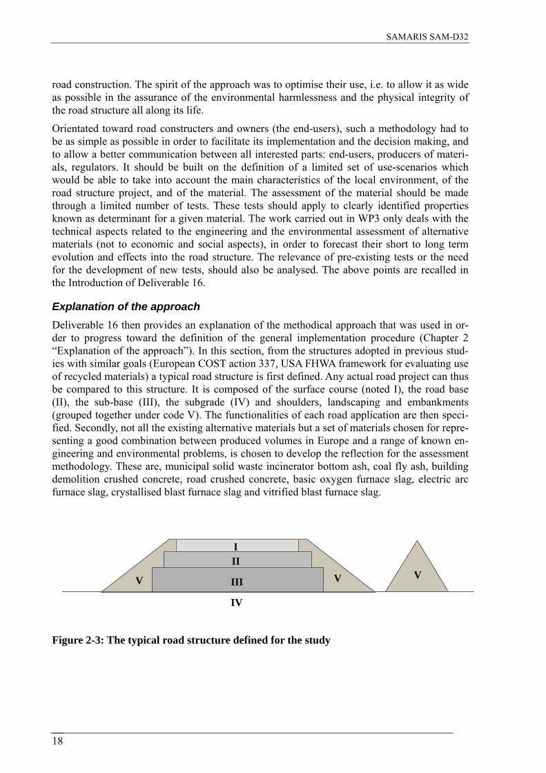
Explanation of the approach Deliverable 16 then provides an explanation of the methodical approach that was used in or-der to progress toward the definition of the general implementation procedure (Chapter 2 “Explanation of the approach”). In this section, from the structures adopted in previous stud-ies with similar goals (European COST action 337, USA FHWA framework for evaluating use of recycled materials) a typical road structure is first defined. Any actual road project can thus be compared to this structure. It is composed of the surface course (noted I), the road base (II), the sub-base (III), the subgrade (IV) and shoulders, landscaping and embankments (grouped together under code V). The functionalities of each road application are then speci-fied. Secondly, not all the existing alternative materials but a set of materials chosen for repre-senting a good combination between produced volumes in Europe and a range of known en-gineering and environmental problems, is chosen to develop the reflection for the assessment methodology. These are, municipal solid waste incinerator bottom ash, coal fly ash, building demolition crushed concrete, road crushed concrete, basic oxygen furnace slag, electric arc furnace slag, crystallised blast furnace slag and vitrified blast furnace slag.
5
25 3
1
IV
5V
IIV III V
I
Figure 2-3: The typical road structure defined for the study
18

SAMARIS SAM-D32
Assessment of the suitability of materials for road applications In Chapter 3 “Assessment procedures per material”, the main physical and chemical charac-teristics of each selected material are then presented (1 – Engineering properties; 2 – Envi-ronmental properties). The technical functions each road application (noted I to V) is usually designed for, is then indicated. This results from a literature review, the questioning of volun-tary experts from Samaris participating countries and the WP3 group own knowledge. In a third step, the ability of the selected materials to fulfil the technical functions of each applica-tion is analysed in order to recommend or to advise against the different combinations mate-rial/application. At that stage, considering the actual road practice, the possibility to meet these applications under a bound (bitumen or cement bound) or the unbound form across Europe, is considered. This leads to the definition of cases for unbound (noted “a”); bitumen-bound (noted “b”); and cement-bound (noted “c”) applications. 11 cases are then considered: I-a (this one is not a classical road use but it corresponds to tracks or some car-parks adapted to light traffic situations); I-b; I-c; II-a; II-b; II-c; III-a; III-c; IV-a; IV-c; V-a. From the initial 88 theoretical combinations the analysis of suitability allows finally to consider 24 cases as unadvisable, should it be for engineering or environmental reasons, or for both. The remain-ing 64 possible cases are sometime indicated with some restriction or precaution conditions.
Figure 2-4: Example of material assessment procedure: leaching of building demolition crushed concrete
pH development - Buffering Capacity test
Organic Material test - TOC or LOI
Granular Leaching test:
TOC or LOI threshold value
Threshold values
Threshold values
Threshold values
Aggreement for use in applications II-a, III-a, IV-a and V-
Monolith Leaching test
Inorganic salts:SO4--
Oxyanions:Cr
Organics:mineral oils,
PAH
Aggreement for use in the designed mixture
Designed bound mixture
Unbound material or mixture
19

SAMARIS SAM-D32
Specific assessment procedures for each material toward its possible application cases are then proposed (they are presented as flow-charts) together with considerations related to the test protocols that are proposed for all these procedures. This applies to engineering and envi-ronmental testing (through chemistry, leaching and eco-toxicity for the later).
Toward a general assessment procedure Then, a general assessment procedure for engineering properties is proposed (Chapter 4 “A general implementation attempt”), it is also presented as a general flow-chart. Through this general procedure, according to its properties, each material among the 8 chosen for the study can be driven toward the different branches of assessment to one of its possible applications. The environmental assessment procedure didn’t give rise to such a new proposal for two rea-sons: un-necessity in one case and impossibility in the other. Regarding the environmental as-sessment through chemistry and leaching, the material specific assessment procedures have previously clearly shown the important degree of integration already reached today thanks to the material behaviour based approach under development. Regarding the assessment through biology and eco-toxicity, the absence today of dedicated assessment protocols and referential calls for more research in that field and made impossible to proposed any practical assessment procedures in the SAMARIS framework. The general methodology for engineering assess-ment reveals different parts in which several materials are assessed the same way, according to the foreseen applications (bound or unbound) and to the role of the material into the layer or mixture (aggregate, filler, binder). These parts, called “main cases”, indicate also how the material has to be assessed on the leaching point of view. The necessity to apply some thresh-old values for some parameters (soluble sulfates, chloride content, organic content, swelling potential, resistance to freeze-thaw, permeability…) is discussed along with these MCs.
Figure 2-5: Levels of testing: a questioning for eco-toxicological assessment (from Trieb-skorn et al. 2001). Necessary complementary work
Necessary complementary work The whole approach used for the development of this methodological proposal was also the opportunity to highlight the remaining difficulties on the way to a future fully general, inte-grated and rational assessment method. Such considerations for future improvements are de-
20
SAMARIS SAM-D32
tailed in Chapter 5 “Considerations for the future”. They apply to the enhancement of future practices (notably to increase knowledge transfer, to encourage synergistic partnerships, to develop research on performance-bases engineering and environmental assessment…), to the development of the concepts of highest possible use and re-use after first use, to the im-provement of generation processes in order to increase the re-use potential of materials, to the consideration of the life cycle analysis approach, the development of differentiated design standards for large and small projects. Lastly, regarding the development of performance-based design strategies, study initiatives are proposed in the field of accelerated pavement testing, environmental risk assessment and bio-monitoring.
Appraisal of the progress achieved The authors have made efforts to make this document an improvement in the decision making process through an improvement in the reliability of the assessment procedure of alternative materials. But they are aware that the proposals made in the present document represent only a step in a longer term process toward a better assessment procedure in the future. Indeed, the knowledge is better than it was a decade ago, but it will continue to progress. Future knowl-edge should be integrated into future revisited assessment procedures. Thus, the Conclusion of Deliverable 16 first emphasises the benefits of the proposal towards the present situation (up-to-date international compilation of the characteristics of 8 important alternative materi-als, recall of the functional role of road applications, proposal of unadvisable and possible ap-plication cases, material specific assessment procedures, evaluation of the pre-existing test methods, progress toward a future property-based general assessment methodology, progress toward the clarification of the concept of use-scenario). Then the Conclusion also recalls the limits of the proposal and the further needs for an improvement of the assessment process (need for the development on new test protocols, need for the setting of threshold values, need for the incorporation of additional properties in the characterisation process in order to evolve toward a more general assessment method, need for an enlarged feed-back from the field, need for recognized assessment system regarding natural targets, need for progress regarding water ingress and transfer into road structures…). Indeed, this work also had for ambition to provide a contribution in the orientation of future research in useful directions. Ideally, a reli-able and fully predictive assessment procedure wouldn’t need field control. However, as the development of such a methodology is part of a long term process in which proposals’ actual effects have to be assessed in the field, the control on road structures and environment thanks to field tests, despite it is not part of the assessment methodology, is of-course necessary to validate or improve proposals.
To enable the reader to refer to the mentioned test methods, an appendix provides their entire list. To enable the comprehension of this multi-disciplinary approach by any specialist, another appendix provides a glossary with concise definitions of the most useful terms.
21

SAMARIS SAM-D32
22

SAMARIS SAM-D32
2.3 Report on test procedure for reaction to fire of pavement materials (D20)
The issue of the reaction to fire of pavement materials was raised in the EU Mandate 124 for Road Construction Products, sparking debate and resulting in conflicting attitudes within na-tional regulations. This paper details the findings from the second phase of the reaction to fire task on pavement fires of the safety and environment work package (Task 4.2), conducted un-der the remit of the SAMARIS research project, which consisted of a number of tasks in-tended to address a range of issues related to the sustainability, development and application of advanced materials for road infrastructures.
The objective of Task 4.2 was to identify the situations and aspects of fire-damage that could be of concern; to this end a research programme was developed split into two distinct phases. In the first phase of the project, a survey of regulators and road authorities was undertaken and a review of potential reaction to fire test methods conducted. Based on the findings from the first phase and following discussions within the Task Group the objectives of the second phase were agreed as follows: • Obtain indicative data relating to the ignition and flame spread characteristics of three
chosen pavement surfaces using the test methodology detailed in EN ISO 9239-1. • Utilise the cone calorimeter test methodology detailed in ISO 5660-1 on the same three
products, to obtain data relating specifically to the critical heat flux required to effect sus-tained flaming and to provide comparative information relating to the heat release charac-teristics of the specimens under the influence of a specified heat flux.
• Determine whether the reaction to fire performance of road pavement material could be used to differentiate between pavement products.
The selection and preparation of suitably representative systems for inclusion in the study was undertaken by TRL Ltd. The three products chosen were selected principally because they were accepted examples of road pavement materials, and included two products with aspects that were expected to exacerbate any adverse reaction to fire characteristics. All of the prod-ucts were manufactured with relatively high levels of organic binder, as this was felt to repre-sent a worst-case scenario. The following road pavement surfaces were examined in the study:
Dense Bitumen Macadam (DBM) Porous Asphalt (PA) Mastic Asphalt (MA)
Figure 2-6: Pavement materials selected for testing for their reaction to fire.
The determination of fire performance characteristics is typically expressed in terms of reac-tion to fire performance and fire resistance. The former can be defined as the response of a
23

SAMARIS SAM-D32
product in contributing, by its own decomposition, to a fire to which it is exposed, under specified conditions, typically expressed in terms of ignitability, spread of flame, heat release and smoke production. The critical radiant heat flux can be considered as the limiting crite-rion for pilot ignition of material i.e. the heat flux below which ignition is not possible. It is sensitive to heat losses from the surface and therefore the orientation and geometry of the sur-face.
Figure 2-7: Elements in the reaction to fire testing of pavement materials
The heat generated from a vehicle fire imposes an external heat flux on the pavement sur-face. Paap estimated that the radiant heat flux incident on the pavement surface during such an incident would be approximately 15 to 25 kW/m² and therefore concluded the pavement material could be considered safe if it achieved a critical flux at extinguishment (CFE) in a radiant panel exposure test of more than 15 kW/m². The maximum imposed radiant heat flux level observed in the current standard reaction to fire flooring tests is approximately 12 kW/m2.
Cone Calorimeter ISO 5660-1 test equipment
Test Specimen for EN ISO 9239-1
Figure 2-8: Testing pavement reaction to fire using EN ISO 9239-1 methodology
24

SAMARIS SAM-D32
Under the current requirements of the Construction Products Directive, the reaction to fire performance of products is classified using EN 13501-1: 2002, in this case, using the provi-sions for flooring products.
Data from EN ISO 1182: 2002 the non-combustibility test and EN ISO 1716: 2002 the gross calorific potential test (PCS) is used for the classification of A1fl products. The A2fl classifica-tion allows for either of these test methods to be used in addition to the radiant panel flooring test, EN 9239-1:2002. Bfl to Dfl classifications utilise both the radiant panel flooring test and the small flame test, EN ISO 11925-2: 2002.
Classification for class Efl is determined from the small flame test alone. It is antici-pated that these products may exceed the performance limits for A1fl since the level of organic material present in binders or as part of recycled aggregate material is likely to be relatively high. In this case, the prod-ucts would require testing to EN 9239-1:2002 as part of their classification proc-ess.
The radiant panel flooring test, EN ISO 9239-1: 2002 evaluates the critical radiant flux below which horizontal flames spread no longer occurs. The pavements materials performed well in this test, attaining a final flame spread of less than 50 mm, and hence a critical heat flux at extinguishment greater than or equal to 11 kW/m², the highest value achievable. It was therefore not possible to distinguish between the three selected pavement materials. This implied that the critical heat flux required for sustained flaming was significantly higher than that generated in the test. Modification of the test apparatus defined in EN ISO 9239-1 to increase the imposed heat flux levels was considered, but was deemed impractical within the scope of the study. It was con-cluded that the EN 13501-1 classification system does not necessarily provide the required level of discrimination between pavement types, with the vast majority of pavement surfaces subjected to the flooring test having the potential to achieve at least a Bfl classification.
Cone calorimeter data - Critical flux for sustained flaming for a dense bitumen macadam pavement
y = 0.0027x - 0.0578R2 = 0.9528
0
0.02
0.04
0.06
0.08
0.1
0.12
0.14
0.16
0 10 20 30 40 50 60 70
Irradiance level (kW/m²)
1/√t
ig (s
-1)
80
Critical flux estimate for dense bitumen macadam
Cone calorimeter data - Critical flux for sustained flaming for a mastic asphalt pavement
y = 0.0023x - 0.0486R2 = 0.9529
0
0.02
0.04
0.06
0.08
0.1
0.12
0.14
0 10 20 30 40 50 60 70
Irradiance level (kW/m²)
1/√t
ig (s
-1)
80
Critical flux estimate for mastic asphalt
Figure 2-9 : Critical heat flux estimates
In order to obtain the response of the pavement products to higher levels of radiant heat expo-sure, the test methodology described in ISO 5660-1 was employed. The time to sustained flaming was recorded at a minimum of five irradiance levels; the reciprocal of the square root of this time was then plotted against the irradiance level incident on the surface of the speci-men. An estimate of the critical radiant heat flux for pilot ignition was found from the point at which the straight line intercepted the incident radiant heat flux axis. The estimated values de-rived from these plots were found to be 22 kW/m² for dense bitumen macadam, 21 kW/m² for
25

SAMARIS SAM-D32
mastic asphalt and 28 kW/m² for porous asphalt. The R-squared values derived from the trend lines indicated an acceptable degree of confidence in the data presented. These critical flux estimates, clarified the fire behaviour observed in the larger-scale EN ISO 9239-1 tests, as the latter was operated at a heat flux approximately half of that required to initiate sustained flam-ing.
The peak heat released from the pavement materials at an irradiance level of 50 kW/m² ranged from 34.4 kW/m² for porous asphalt to 94.0 kW/m² for dense bitumen macadam, while the total heat released during the thirty-minute test duration ranged from 24.5 MJ/m² (porous asphalt) to 87.4 MJ/m² (DBM). The data obtained at an irradiance level of 35 kW/m² were lower than this, and showed more variability, as the tests were undertaken at an irradiance level close to that of the critical flux. It was concluded that the cone calorimeter test, ISO 5660-1, provided an effective means of discriminating between the reaction to fire perform-ance of pavement materials.
The critical flux values measured for the pavement materials are considered reasonably high in relation to the other flammable materials present in a road vehicle, it is therefore suggested that the vehicle would become involved at an earlier stage and would make a larger contribu-tion than the pavement material itself. However, in a confined area such as a road tunnel, the heat flux radiated back from the hot smoke layer and the tunnel walls would increase the probability of the pavement igniting and making a more significant contribution to the fire growth than in an open road scenario.
26

SAMARIS SAM-D32
2.4 Environmental annexes to road product standards (D24)
SAMARIS Work Package 4, entitled “Safety and Environmental Concerns in Material Speci-fications”, was a part of the pavement stream and primarily concentrated on addressing safety and environmental aspects in product standards, for example the detection and classification of hazardous characteristics in road materials. The WP was organised in three tasks.
Deliverable 24 is the output of task 4.3 and is entitled “Environmental Annexes to Product Standards”. The aim of task 4.3 was to make proposals about how environmental sustainabil-ity requirements of road materials could be included into the European Product Standards for road materials in the form of an annex.
Justification for such annexes is derived from the goal of the European Commission to incor-porate environmental requirements into the second generation of the European Product Stan-dards for construction materials according to the essential requirement “Hygiene, health and environment”. This subject was not a part of the mandates for the different construction ma-terials that have been standardised to date. Therefore, the present first generation of European standards for road materials does not include any regulations concerning environmental speci-fications.
Step No. Action Input from Example
1 Identification of relevant road materials
WP 3 Industrial by-products, tar bound materials
2 Identification of
appropriate European Product Standards
CEN/TC 154 CEN/TC 227
EN 13043 EN 13108-8 EN 13285
3
Identification of hazardous components
and appropriate test method
WP 3 Task 4.1
Literature
Leaching test Detection of sulphur,
PAH
4 Drafts of annexes to Product Standards
Figure 2-10: Stages involved
In relation to these construction materials, the main focus of task 4.3 is on recyclable (road) materials and industrial by-products which can be used as aggregates for unbound and bound mixtures. For natural aggregates that have been used in road materials for generations, the environmental compatibility is assumed to be given by default and there is no need for further testing.
27

SAMARIS SAM-D32
RELEVANT ROAD MATERIALS
IInndduussttrriiaall bbyy--pprroodduuccttss •• CCrryyssttaalllliizzeedd ((oorr aaiirr ccoooolleedd)) bbllaasstt ffuurr--
nnaaccee ssllaagg ((CCBBFF ssllaagg)) •• VViittrriiffiieedd ((oorr ggrraannuullaatteedd)) bbllaasstt ffuurr--
nnaaccee ssllaagg ((VVBBFF ssllaagg)) •• BBaassiicc ooxxyyggeenn ffuurrnnaaccee ssllaagg ((BBOOFF ssllaagg)) •• EElleeccttrriicc aarrcc ffuurrnnaaccee ssllaagg ((EEAAFF ssllaagg)) •• CCooaall ffllyy aasshh ((CCFFAA)) •• BBooiilleerr ssllaagg ((BBSS)) •• FFllyy aasshh ffrroomm lliiggnniittee ccoommbbuussttiioonn
((FFAALLCC)) • MMuunniicciippaall ssoolliidd wwaassttee iinncciinneerraattoorr
bboottttoomm aasshh ((MMSSWWIIBBAA))
RReeccyycclleedd mmaatteerriiaallss
•• CCrruusshheedd mmiinneerraall ccoonnssttrruuccttiioonn wwaassttee ((CCMMCCWW))
•• RReeccllaaiimmeedd aasspphhaalltt ((RRAA)) • TTaarr bboouunndd rreeccllaaiimmeedd rrooaadd mmaatteerriiaall
((TTBB))
DECISIVE HAZARDOUS CHARACTERISTICS
Hazardous cha-racteristic
CB
F sl
ag
VB
F sl
ag
BO
F sl
ag
EA
F sl
ag
CFA
BS
FAL
C
MSW
IBA
Kind of de-termination
Hazardous characteristic
CM
CW
R
A
TB
pH-value × × × × × × × × pH-value × El. cond. × × × × × × × × El. cond. × Boron × × × × Chloride × Vanadium × × × × ×
Leaching test
Sulphate × × Sulphate × × × Hydrocarbons × Barium × × × × PAH (EPA) × × × Chromium tot. × × × ×
Content by mass
Sulphur ×
Figure 2-11: Decisive hazardous characteristics of industrial by products and recycled materials when considered for use in road pavements
In addition to the input from other tasks of Work Package 4, input has been derived from other Work Packages of this project, particularly Work Package 3 dealing with the assessment of alternative materials.
After identifying the relevant road materials which are used within this task, the appropriate European Product Standards have been identified. The next step was to detect the potential hazardous components and the appropriate test methods. Finally, drafts of annexes to Product Standards were developed, duly formatted so as to be suitable for future standardisation.
28

SAMARIS SAM-D32
Concerning industrial by-products, the following residuals from steel production and from burning of coal and of lignite as well as municipal solid waste incinerator bottom ash have been identified as being relevant for possible use in European countries: • Municipal solid waste incinerator bottom ash • Crystallised (or air-cooled) blast furnace slag • Vitrified (or granulated) blast furnace slag • Basic oxygen furnace slag • Electric arc furnace slag • Coal fly ash • Boiler slag • Fly ash from lignite combustion.
The range of the essential chemical constituents of these materials has been described. With regard to the processed municipal solid waste incinerator bottom ash, the range of essential components in its ash are listed.
Concerning recyclable materials, it was found to be advisable to deal not only with mineral construction waste but also to deal separately with bitumen-bound material (reclaimed as-phalt) and with tar-bound materials.
Tar, especially coal tar and other tar distillates, was used as a road binder in the past in many European countries because its hazardous properties were not widely known at that time.
The hazardous characteristics of the listed materials are mostly chemical properties which re-fer, in each case, to a certain concentration in an eluate.
The chemical characteristics relevant for the European countries are listed in tables that dif-ferentiate between the different material. The tables do not include threshold values because they are also dependant on the test method used, which, together with the requirements, have not been the same in all the European Countries for a long time.
With regard to the relevant standards, the main focus was on the standards of the following Technical Committees of CEN: • CEN/TC 336 “Bituminous binders” • CEN/TC 154 “Aggregates” • CEN/TC 227 “Road materials”
Most of the harmonised European standards are relevant as well as, in some cases, the “volun-tary” European standards.
Starting from the considerations discussed above, the last chapter proposes drafts for envi-ronmental annexes to product standards. As examples for typical future product standards, environmental annexes for hEN 13043, hEN 13108-1, hEN 13108-8, hEN 13242 and EN 13285 have been drafted.
In addition to these environmental annexes, a separate annex dealing with possible handling of tar-bound reclaimed road material (TB) has been proposed in a separate section.
29

SAMARIS SAM-D32
The proposed drafts in the Appendices of the report should be a help for people involved in standardisation, particularly those on CEN Technical Committees TC154, “Aggregates”, and TC227, “Road materials”.
Beyond the recommendations given, there is also a need to standardise the methods for analy-sis (e.g. PAH and sulphur in reclaimed asphalt) in the form of supporting documents. Propos-als for these methods are given in Deliverable N° 23.
The hope remains that such environmental annexes will expand into the next generation of road product standards in order to enforce the safety when dealing with industrial by-products and recycled materials.
The handling of tar-bound reclaimed road material is covered separately due to the fact there is no European standard for this material. It can be stated that the re-use of that material is possible but only in cold mixtures in order to avoid air pollution by dangerous components, such as PAH.
30

SAMARIS SAM-D32
2.5 Procedures for identifying hazardous components in materials for asphalt (D23)
A key objective of SAMARIS Work Package 4, Safety and Environment, was to encourage the use of recycled and secondary materials in pavements by detailing how such materials shall be selected and tested in order to secure satisfactory performance, environmentally as well as functionally. D23 reports the outcome of the task of this work package which ad-dressed the detection of hazardous components in materials to be recycled.
The use of partial replacement of the traditional component materials of asphalt with alterna-tive secondary materials is increasing. These secondary materials, which are often waste- or by-products from other industries, need to be checked in order to ensure that they will per-form satisfactorily for the intended service life in terms of both performance and safety. In-formation on health, safety and environmental (HSE) issues must be considered when using secondary and by-product materials (as new materials for road construction) and recycled ma-terials for sustainable road construction. Health and environmental risks are a function of both the degree of exposure and the nature and concentration of the chemicals. The first step of risk assessment is the substance-specific hazard identification. A proper and comprehen-sive risk assessment of the materials during the whole life cycle is required.
There are several materials known to have been used in pavements that require care should such pavements be used for recycling. These materials include tar, sulphur and asbestos. However, for any procedure to be general and allow for new potentially hazards to be consid-ered, the circumstances that maximise the risk during the extraction of the old pavement, to-gether with the manufacture, paving and use of the recycled material, have to be included in the procedure. The situations during the life cycle of recycled asphalt that could, but gener-ally do not, induce hazards were considered to be: • Airborne particulates derived from pulverisation during milling off and crushing. • Fumes arising from heating during mixing. • Spontaneous ignition during heating. • Leaching once installed. • Reaction to fire in tunnels.
Having identified the scenarios to be assessed, a simple procedure was developed around them that is intended to provide a consistent approach to assessing the health and safety im-plications of using recycled and/or secondary components. However, the use of the procedure will be precautionary because, in most cases, there will be no hazards present. It is envisaged that the procedure should be used for type testing possible new component materials and/or combinations of components rather than part of the mix design procedure for routine mix-tures. When hazards are found, the potential hazard should not necessarily mean that the relevant component material cannot be used in asphalt.
Based on these known hazardous component materials and the more general situations identi-fied in the procedure, suitable tests were identified to support the procedure.
Coal tar is a complex liquid mixture of hydrocarbon compounds that is derived, along with coke, from the destructive distillation of coal in cooking ovens. The hazards of coal tar are now well documented and relate to the hazards from its constituents. A false identification of RA as containing tar has a huge economical consequence because it restricts reuse.
31

SAMARIS SAM-D32
Nil classification for new component
Start
Yes Yes Existing pave-
ment? Is tar present?
Add “T” to
classification No
Yes Is sulphur pre-
sent? Add “S” to
classification No
No
Yes Yes Abraded during processing?
Are airborne par-ticulates (including
fumes) present?
Add “P” to classification
No No
Yes Yes Raised above 90 °C during proc-essing or mixing?
Can ignite sponta-
neously? Stop, material
unsuitable
No No
Yes Yes Will the mixture be subject to mois-
ture?
Can leaching oc-cur?
Add “L” to classification
No No
Yes Yes Will the mixture be used in tunnels?
Will react ad-versely to fire?
Stop, material unsuitable
No No
No Has the material a nil classification?
Material can be used with care based on classification
Yes
Material can be used without particular care for hazards
Figure 2-12: Proposed methodology of testing for hazards from alternative components
Therefore, the preferable protocol has to be reliable in identifying the hazard linked to the presence of tar, namely the polycyclic aromatic hydrocarbons (PAH) content rather than for the presence or absence of coal tar itself. Consequently, research was undertaken on the de-velopment of an approach combining a fast preparation of samples and a precise quantifica-tion of individual PAHs. The option selected is to collect samples from the source and, after
32

SAMARIS SAM-D32
recovering binders from RA, to test the recovered binders in the laboratory to precisely assess the environmental acceptability of the material. The test procedure involves extracting and preparing the binder before placing it onto a thin layer chromatography plate for scanning the fluorescent spots. This laboratory test method performs well as a rapid, practical, efficient and suitable method of determining PAHs levels in asphalt.
Figure 2-13: Plot to determine the presence of tar through PAHs
Sulphur is an element that has been well-known since antiquity that was used in road surfac-ings in the 1980s and 1990s. Elemental sulphur (solid) in itself is not a danger, but the main the presence of added elemental sulphur in bitumen and/or asphalt can release hydrogen sul-phide, a poisonous gas, into the air if heated above about 160 °C. The research focused on the development of a rapid and simple way to quantify sulphur by inductively coupled plasma – atomic emission spectrometry. The spectrometric analysis requires a pre-binder extraction be-fore analysing. If a part of the sulphur is suspected to be remaining in the mineral part after extracting, the use of the elemental analyses is recommended despite the fact these protocols are heavier to implement. A new way to prepare the binder was developed consisting of emulsifying the binder in water and optimising the settings on the classical apparatus. This laboratory test method performs well for a rapid, practical, efficient and suitable determina-tion of sulphur content in binders recovered from RA.
During milling off and crushing of aged pavements, potential particulates can be derived from pulverisation. This inorganic dust can contain components regarded as hazardous. Similarly, hazardous compounds can be released when the temperature is increased during the recycling process. The methods for identifying airborne particles (including condensed organic va-pours) serve different purposes including the identification of hazardous components in re-claimed asphalt, for which three steps or routes are suggested: • Determination of hazardous components in the fines fraction (e.g. <100 µm or <75 µm or
<63 µm) in a representative sample of reclaimed asphalt. • Assessment of airborne particles release, collection and analysis in the laboratory.
33

SAMARIS SAM-D32
• Personal exposure measurements and sampling procedures in the field. A laboratory method is proposed in order to be able to carry out, within the same set-up, labo-ratory experiments at room temperature and at high(er) temperatures to collect airborne parti-cles including condensed vapours.
Reclaimed Asphaltsample
(Personal)exposure
Assessmentairborne particles
Fines in sample<100 µm or <63 µm
Collectedparticles
Physical and Chemical analyses
Collectedparticles
Collectedparticles
Reclaimed Asphaltsample
(Personal)exposure
Assessmentairborne particles
Fines in sample<100 µm or <63 µm
Collectedparticles
Physical and Chemical analyses
Collectedparticles
Collectedparticles
Figure 2-14: Approach for assessment of airborne particles
Spontaneous ignition can occur when constructing a road through a contaminated site, when using colliery spoil as a sub-base or fill material or when using a material that can ignite dur-ing the heating process involved in recycling or mixing bitumen. A review of the available screening tests and detailed tests identified the ramped basket test because the test approach has been used successfully for many years, it involves no potential risks, it is relatively sim-ple,
34

SAMARIS SAM-D32
Figure 2-15: Temperature-time plot of coal asphalt samples
it can be used to determine both the potential for combustion and the isothermal behaviour of the material and it simulates the condition in dryers. Trials were undertaken with a range of asphalts to confirm its applicability to road materials.
The test methods are given as Appendices in the format used by CEN to allow for their adop-tion as European Standards. In addition, advice is given on what to do should the results indi-cate that there could be a potential hazard. However, it is anticipated that the tests will dem-onstrate that the hazards are not present in most of the materials used for road construction.
35

SAMARIS SAM-D32
36

SAMARIS SAM-D32
2.6 Development and validation of a method of prediction of structural rutting on unbound pavement layers (D27)
Objectives of the research The aim of subtask 5.2 of SAMARIS, dealing with permanent deformations of unbound pavement layers, was to develop a performance-based approach for the characterisation of the resistance to permanent deformations of unbound granular materials. Actual empirical charac-terisation methods have been developed for traditional crushed aggregate materials, and are not always applicable to alternative materials. The aim here is to develop an approach based on cyclic loading tests, applicable to all materials, irrespective of their origin.
Therefore, two main objectives have been defined for the work of subtask 5.2: First to de-velop a tests method for characterising the resistance to permanent deformations of unbound granular materials. Secondly, to develop a method of prediction of rutting of unbound layers in pavement structures, applicable to pavement design.
Rutting of unbound layers is particularly important for low traffic pavements, with a thin bi-tuminous overlay, where it generally represents the main degradation mechanisms. It is also important in bituminous airport pavements, where the bituminous layers are thicker, but where the very high loads lead to high levels of strain in the unbound subbase or subgrade.
Recently, some test procedures to determine the resistance to rutting of unbound granular ma-terials have been proposed (based mostly on cyclic triaxial tests). Several models, describing the permanent deformation behaviour also exist. However, practical approaches for calculat-ing the rutting of unbound pavement layers are lacking.
Stress
Time
σ1σ3
σ1
σ 3
Stress
Time
σ1σ3
σ1
σ 3
Figure 2-16: Principle of the cyclic triaxial test and view of the LCPC equipment
37

SAMARIS SAM-D32
In the first part of the work of task 5.2 of SAMARIS, different permanent deformation models for unbound granular materials have been selected, and evaluated by comparison with cyclic triaxial test results. From these comparisons, two models have been selected: one simple em-pirical model, and one elasto-plastic model. This work has been presented in the intermediate report SAM-05-DE-10, “Selection and evaluation of models for prediction of permanent de-formations of unbound granular materials in road pavements” [Hornych et al., 2004].
In the second part of the work, the objective was to develop the computation method for the prediction of rutting and to evaluate it, by comparison with rutting of real pavements.
Development of Methods of prediction of rutting of unbound pavement layers The program which has been developed, called ORNI, is based on finite element calculations, and is implemented in the finite element program CESAR-LCPC. The program, which devel-opment was started by Heck [2000], for the prediction of rutting of bituminous materials, is based on an original calculation procedure. In pavement problems, unbound materials are submitted to very large numbers of load cycles, and the permanent strains generated at each cycle are very small. It is thus possible to simplify the problem, and decouple the calculation of the resilient behaviour (which is assumed to be constant and independent of the number of load cycles) and the calculation of the permanent strains. Thus, a calculation method in three steps is proposed:
The first step consists in calculating the resilient stress fields in the pavement structure, under various loading conditions, characterising the loading history of the pavement. This calcula-tion is performed in 3D, using linear elastic, non linear elastic or visco-elastic models.
The second step consists in using these resilient stresses to calculate, at different points in the pavement , the permanent strains resulting from the repeated application of these stresses. The permanent strains are calculated in 2D, in the plane perpendicular to the direction of the mov-ing loads.
The third step consists in performing a structural calculation, to determine the corresponding displacements (rut depths).
It is possible to take into account in the modelling variable loading conditions, characterised by: different material properties, different temperatures, different types of loads, different loading speeds, and different lateral positions of the load. To accelerate the calculations, the life of the pavement is divided in periods, in which a statistical distribution of the loads is as-sumed. For each period, the order of application of the loads is not taken into account, and a mean increment of permanent deformation is calculated statistically. This avoids calculating the permanent deformations cycle by cycle.
Within the time of the SAMARIS project, only the empirical permanent deformation model has been implemented in the ORNI program. Further work will be required to implement also the elasto-plastic model. It will also be possible to add models for permanent deformations of the bituminous layers and of the subgrade.
Test performed with the ORNI program have shown that qualitatively, the results obtained are reasonable. They have also indicated that the temperature in the asphalt layers, which modi-fies the stresses transmitted to the unbound layers, has a strong influence on the rutting of the
38

SAMARIS SAM-D32
unbound layers. The level of the load is also important, but the lateral distribution of the loads appears of lower importance.
Figure 2-17: Example of rut profile predicted with ORNI (dual wheel load, constant lat-eral position)
The ORNI program is an advanced modelling method, which leads to relatively long calcula-tion times (several days if complex loading conditions and a large number of loads are simu-lated). For this reason, a second, simplified, routine rut depth prediction method has also been developed. The general principle of the method is similar to that of ORNI, but with two main simplifications: only one type of load condition is considered, and only the vertical strains and displacements are calculated. Thus, after determining the resilient stress field (which is done in 3D, using a finite element calculation), a simple analytical calculation is used to de-termine the permanent strains at different depths, and then to integrate them in the vertical di-rection.
The two rut depth prediction methods have been compared, and it appears that for simple loading conditions, the routine method gives results in good agreement with those of ORNI. Thus, this routine method appears as a promising tool for practical applications like design.
Selection and analysis of a full scale experiment for the validation of the rut depth prediction methods. Then, an important work has been performed, in order to validate the two rut depth prediction methods, by comparison with experimental pavement behaviour. It has been decided to use for that purpose the results of a full scale experiment on low traffic pavements, performed on the LCPC pavement testing facility. This experiment presented several advantages: It is a real full scale experiment, where the pavements have been tested under real heavy vehicle loads (65 kN dual wheel loads) and in outdoor conditions, over a period of several months. Five dif-ferent structures were tested, and two million loads were applied. A large amount of experi-mental data was available, including measurements of the response of the pavements under different load levels and loading speeds. In counterpart, the analysis of the experiment has shown that working with variable climatic conditions, leading to variable temperatures and
39

SAMARIS SAM-D32
moisture conditions in the pavement layers can be a disadvantage, for model validation, be-cause these variable conditions cannot be exactly simulated.
The experiment was performed between May and September 2003, in relation with another project (study for the French Road Directorate), but its results were analysed in detail within the work of SAMARIS. Five structures were tested in the experiment, but only two were used for the modelling work: structure 1, which had a 5 cm thick bituminous wearing course, over a 20 cm thick granular base, and structure 4, with an 8 cm thick bituminous wearing course, over a 50 cm thick granular base.. The pavements were instrumented to measure strains in the various layers, water contents, and temperatures.
UGM
Soil
Structure 46.5 cm
50 cm
2.24 m
UGM
Soil
Structure 46.5 cm
50 cm
2.24 m
Figure 2-18: View of the LCPC accelerated pavement testing facility and pavement structure used for modelling
As expected, the main distress observed on the experimental pavements was rutting, with av-erage final levels of rutting of 25 mm on structure 1 and 16 mm on structure 4. This rutting occurred mainly in the unbound layers, with only about 5 mm of rutting due to the bituminous layers. Analysis of the environmental conditions (temperature, moisture) indicated important variations of temperature in the bituminous wearing course during the experiment (between approximately 10° C and 35°C). The TDR measurements showed relatively constant moisture conditions in the subgrade (with a water content increasing with depth), but significant varia-tions of water content in the upper part of the granular layer, indicating that water has infil-trated through the pavement surface, and has been retained in the granular layer, due to its relatively low permeability.
The database of results from the full scale experiment (transducer measurements and in situ tests) has been analysed, and appropriate measurements for the evaluation of the models of prediction of the resilient behaviour (module CVCR of CESAR – LCPC) and of the perma-nent deformations (module ORNI and routine rut depth prediction method) have been se-lected.
40

SAMARIS SAM-D32
Experimental programme of triaxial tests on the unbound granular material The bituminous and unbound materials from the full scale experiment have been subjected to detailed laboratory studies. The test on the unbound granular material have been performed within the SAMARIS project. The programme included the identification of the material, and three types of mechanical performance tests: monotonic triaxial tests, and two types of cyclic triaxial tests: resilient behaviour tests and permanent deformation tests.
The study of the resilient behaviour confirmed that the resilient behaviour of the unbound granular material is well described using the non linear elastic Boyce model, modified to take into account anisotropy [Hornych et al., 1998].
Two programmes of permanent deformation tests were performed. In the first programme, performed during the full scale experiment, the material was tested at water contents of 4 % and 5 %. In the second programme, performed later, additional higher water contents were tested (5, 6 and 7%), to reproduce the high water contents measured in the upper part of the unbound granular layers.
Some difficulties were encountered with the results of the second test programme. First, the permanent deformations obtained in the second test programme at 5 % were higher than those obtained in the first test programme. This was attributed to the fact that the material used in the second test programme (taken from the quarry, after the experiment), was not exactly identical to the material from the first test program. In addition, it was impossible to test the material at 7 %, because the specimens were impossible to compact at this high water content. Loss of water occurred during the compaction, leading to a final water content close to 6 %.
All the permanent deformation tests were interpreted using the empirical model. It was found that the empirical model predicts well the evolution of the permanent axial strains, except in the tests at w = 6 % (second test programme); where in particular the test with q / p = 2 was not well predicted. Additional test could not be performed during the time of the project, to verify the experimental results.
The elasto-plastic model was evaluated only on the results of the first test programme, be-cause monotonic triaxial tests (also required for this model) were performed only in the first test programme. Satisfactory predictions were obtained both for the monotonic tests and for the cyclic tests.
Modelling of the resilient behaviour of the experimental pavements The first part of the modelling work consisted in modelling the resilient response of the pave-ment structures, with the module CVCR of CESAR-LCPC. CVCR is used in the method of prediction of rutting, to determine the stress fields in the pavement. In addition, calculations were also made with the multi-layer linear elastic program ALIZE, used in France for routine pavement design.
Modelling was performed for structures 1 and 4 from the full scale experiment. With CVCR, the behaviour of the unbound granular material was described using the anisotropic Boyce model, with parameters determined from the triaxial tests. The bituminous material and the soil were assumed linear elastic. The elastic modulus of the bituminous material was deter-mined from laboratory complex modulus tests.
The models were first calibrated on experimental results obtained with a load of 65 kN and a speed of 43 km/h. the objective was to adjust the modulus of the subgrade, in order to fit well
41

SAMARIS SAM-D32
the experimental transducer measurements. With ALIZE, both the modules of the soil and of the UGM were fitted on the in situ results.
Then the models were used, with the same parameters, to predict the behaviour for different load levels (45, 65, and 85 kN) and different loading speeds (3, 6, 43 and 72 km/h). It was found that:
• both ALIZE and CVCR gave satisfactory predictions of the tensile strains at the bottom of the asphalt layers, for different loading speeds. This confirms the good representation of the asphalt layer modules determined from the laboratory complex modulus tests.
• CVCR, which takes into account the non linear behaviour of unbound granular materi-als, was able to predict better the vertical strains in the unbound granular layers and in the subgrade than ALIZE. In particular, the variations of these vertical strains with load level were better described with CVCR.
Globally, despite some scatter in the experimental results, the study confirmed that CVCR; with unbound granular material parameters determined from the laboratory triaxial tests, pre-dicts well the experimental resilient behaviour.
Modelling of the permanent deformations of the experimental pavements Modelling of rutting was performed only for structure 4 from the full scale experiment. In the simulations with the programme ORNI, an attempt was made to reproduce as closely as pos-sible the experimental conditions (lateral wandering of the loads, variable temperatures). Sev-eral simulations were successively performed, considering:
Several different temperature distributions. It was found that the value of the temperature in the asphalt layer has a strong influence on the rutting of the unbound granular layers. Sev-eral simulations, with different descriptions of the temperature variations, have shown that the order of application of the different temperatures is not so important, as long as the number of loads applied at each temperature is correctly simulated. An “equivalent temperature”, leading to the same rut depth as the experimental, variable temperatures, has also been determined: its value is approximately 22.5 °C.
Several different water contents of the unbound granular material. The results indicated a large difference between the predictions based on the model parameters from the first test pro-gramme and from the second test programme, made on different batches of material. The in-fluence of the water content was less important. Additional experimental studies would be needed to determine the reason for these differences, which could be due to differences in grading and quality of fines of the two samples of material. The results from the first test pro-gramme seem to be more representative, as the material from the first test programme is the one effectively used for the construction of the pavements.
The permanent deformations of the soil. Permanent deformation parameters have also been determined for the soil (at a water content of 8 % only), and the rutting of the soil was simu-lated. The results indicate a significant contribution of the soil to the total rutting (about 40 % of the total rut depth).
42

SAMARIS SAM-D32
0
2
4
6
8
10
12
0 200000 400000 600000 800000 1000000 1200000 1400000 1600000 1800000
Number of load cycles
rut d
epth
(mm
)
min experimentmean experimentmax experimentORNI - T=23°ORNI - T=27°ORNI - T=35°
Figure 2-19: Comparison of measured rut depths and predictions with ORNI (rutting of UGM only, different temperatures)
0
2
4
6
8
10
12
14
0 200000 400000 600000 800000 1000000 1200000 1400000 1600000 1800000
Number of load cycles
rut d
epth
(mm
)
min experimentmean experimentmax experimentORNI - T=23°ORNI - T=27°ORNI - T=35°
Figure 2-20: Comparison of measured rut depths and predictions with ORNI (rutting of UGM and subgrade, different temperatures)
Finally, the most reasonable predictions of the experimental results were obtained with the pa-rameters of the UGM from the first test programme, and taking into account the permanent deformations of the soil. With these hypotheses, the final rut depth predicted with ORNI (after 2 million loads) was 6.4 mm, compared with experimental values ranging between 8.1 and 11.2 mm (deformations of the granular layers and of the subgrade). With the same hypotheses,
43

SAMARIS SAM-D32
the routine level prediction method led to a final rut depth of 7.4 mm, slightly higher than that predicted by ORNI.
These results represent the first evaluation of the two proposed rut depth prediction methods, and the first comparison with real pavement behaviour. The results are encouraging, taking into account the difficulty to model accurately the behaviour of a real pavement, subject to variable climatic conditions (temperature, moisture), which have a strong influence on the permanent deformation behaviour. The study will have to be pursued, in particular by making simulations with higher water contents of the granular material (which will require additional laboratory tests on the unbound granular material), and by modelling also the behaviour of the other structures tested in the full scale experiment.
For the validation of the permanent deformation models, comparisons with a simpler experi-ment, performed under better controlled environmental conditions (constant temperature, con-stant moisture) would also be very beneficial.
44

SAMARIS SAM-D32
2.7 Permanent deformation of bituminous bound materials in flexible pavements – evaluation of test methods and prediction models (D28)
Scope The SAMARIS Work Package 5 team with the title “Performance-based specifications” was concerned with the development, calibration and validation of different test methods and pre-diction models for permanent deformation behaviour in unbound granular and bituminous materials. Within the work described in D28 a couple of empirical tests (mainly wheel track-ing tests with different testing devices) and fundamental tests (i.e. cyclic compression tests) that are specified in the new European Standards (EN 13108 series) have been conducted on conventional and alternative bituminous bound materials in order to compare and evaluate these test methods. In addition data fitting methods were developed to facilitate the test re-sults from fundamental test to identify material parameters for advanced rheological models to simulate permanent deformation in road structures.
Materials and sample preparation In this project two types of materials have been used to evaluate the different test methods to address permanent deformations of HMA: the first ones were conventional surface and base HMA materials that were cut out from a non trafficked bituminous pavement structure of an accelerated loading test (ALT) facility in Switzerland. This test pavement was used for a full scale rutting experiment within the European FORMAT project. The second type of materials were bituminous surface and binder layers, consisting of alternative HMA, that were made of steel slag, crushed railroad track ballast and recycled asphalt, from a test pavement in Den-mark. Almost all specimens were cut out from both test pavements and sent to the different WP5 partners for testing; only specimens for triaxial tests were prepared with a roller segment compactor in the laboratory. Table 2-1 and Figure 2-21 show the main characteristics of these materials.
Table 2-1: Overview of different materials and abbreviations
Conventional sur-face material
Conventional base material
Alternative sur-face material
Alternative binder mate-
rial Abbreviation AB11s HMT22s AB11t ABB16
Bitumen 50/70 50/70 70/100 40/60 Penetration [1/10 mm
@25°C] 34 34 91 47
Temperature R&B [°C] 56,2 56,2 43,8 49,8 Binder content [mass-%] 3,8 5,6 5,2 5,4
45

SAMARIS SAM-D32
0102030405060708090
100
0.01 0.1 1 10 100sieve size [mm]
pass
ing
% [m
-%]
AB11s
0102030405060708090
100
0.01 0.1 1 10 100sieve size [mm]
pass
ing
% [m
-%]
AB11t
0102030405060708090
100
0.01 0.1 1 10 100sieve size [mm]
pass
ing
% [m
-%]
HMT22s
0102030405060708090
100
0.01 0.1 1 10 100sieve size [mm]
pass
ing
% [m
-%]
ABB16
Figure 2-21: Comparison of measured rut depths and predictions with ORNI (rutting of UGM and subgrade, different temperatures)
General set-up parameters for empirical and fundamental test methods All different types of test methods for susceptibility to permanent deformation of bituminous mixtures described in the EN 12679 series could be compared to each other with the same as-phalt mixture materials (conventional and alternative) for the first time.
Table 2-2: General set-up parameters for the different wheel tracking test methods
Test method Abbreviation Load Tempera-ture
Fre-quency
Contact surface
Tire pres-sure
[N] [°C] [Hz] [mm²] [kPa] WTT full scale test machine
DART @ Danish Road Institute DRI (DEN)
ALT-DART 45000 +40 up to +20°C ~ 2 ~71000 800 (dual
wheel)
WTT full scale test machine ALT @ ETH Lausanne (CH)
ALT-LAVOC 45000 +40°C ~ 4 ~71000 800 (single
tire) WTT large size device (EN12697-
22) @ LCPC (FRA) WTT-LS 5000 +50 & +60°C 2 ~7500 600
WTT small size device WATER (EN12697-22) @ Danish Road
Institute DRI (DEN)
WTT-SS-WATER 700 +50 &
+60°C 0,88 ~1900 -
46

SAMARIS SAM-D32
Test method Abbreviation Load Tempera-ture
Fre-quency
Contact surface
Tire pres-sure
[N] [°C] [Hz] [mm²] [kPa] WTT small size device AIR
(EN12697-22) @ Transport Re-search Lab TRL (UK)
WTT-SS-AIR 700 +50 &
+60°C 0,88 ~1900 -
In addition to these performance-related tests (wheel tracking tests WTT) and performance-based tests (cyclic compression tests CCT) described in the EN standards, two full scale test-ing devices (ALT) ran permanent deformation tests on two different test site pavements with conventional and alternative materials. Table 2-2 gives a short overview of the set-up parame-ters from the empirical test methods WTT, Table 2-3 shows details of the fundamental test methods CCT.
Table 2-3: General set-up parameters for cyclic compression test methods
Test method Abbreviation Load/ Load amplitude
Tempera-ture
Fre-quency
Contact surface
Confining pressure
[kPa] [°C] [Hz] [mm²] [kPa] Uniaxial cyclic
compression tests (EN12697-25 Part A)
@ SHELL France (FRA)
UCCT 100 +40 & +50°Cload pulse time=0.2 s
~ 5 Hz ~8000 -
Triaxial cyclic compression tests (EN12697-25 Part B) @ University of Technol-ogy Vienna ISTU (AUT)
TCCT 400 / 600 A) +40 & +50°C
B) 3 Hz ~8000 50 / 150C)
A) ±200 kPa for base materials and ±300 kPa for surface materials (according to European Standard EN13108-20)
B) +40°C for base materials and +50°C for surface materials (according to European Standard EN13108-20) C) 50 kPa for base materials and 150 kPa for surface materials (according to European Standard EN13108-20)
Test results of full scale testing devices (ALT) The rut depth results of both full scales accelerated loading test machines (ALT) can be sum-marized as follows: the ALT-DART is the only WTT device tested that offers the possibility to test a whole pavement structure and to maintain a temperature gradient (see Table 2-2). Fur-thermore, the maintenance of a temperature gradient in the bituminous pavement structure during the ALT-DART tests significantly reduces the resulting permanent deformations (see right figure in Figure 2-22).
Besides large differences between the rut depth developments in the ALT-LAVOC tests under well defined environmental conditions, and rut depths in the ALT-DART on the same bitumi-nous pavement structure, under comparable conditions, were observed. The ALT-DART pro-duced significant lower ruts then occurred in the ALT-LAVOC test pavement although the temperature gradient of 5°C between the surface and the bottom of the bituminous base layer at ALT-LAVOC that was not maintained in the ALT-DART machine (see left figure in Figure 2-22). This can be contributed to:
47

SAMARIS SAM-D32
• different confinement and foundation conditions of the bituminous pavement layers in the ALT-DART machine in respect to real pavements, simulated in the ALT-LAVOC test device (asphalt pavement specimen mounted in steel frames in ALT-DART),
• different loading situations since the lateral wander, type of wander (systematically/ ran-domly distributed) and tire types (super single vs. dual tires) were not the same.
02468
101214161820
0 20000 40000 60000 80000 100000
load cycles n [-]
rut d
epth
[mm
]
ALT-LAVOC Super SingleALT-DART Dual wheel
0
2
4
6
8
10
12
14
0 20000 40000 60000 80000 100000
load cycles n [-]
rut d
epth
[mm
]
ALT-DART – alt. mat.- dual wheel WITHOUT temp-gradient
ALT-DART – alt. mat.–dual wheel WITH temp-gradient
Figure 2-22: ALT DART & ALT LAVOC test results for AB11s & HMT22s – rut depths RD in mm vs. load cycles (left figure) and ALT-DART test results (right fig-ure) on AB11t & ABB16 with (+20° up to +40°C, red dotted lines) and with-out (+40° in whole pavement layers, blue solid lines) temperature gradient in the test pavement.
Test results of laboratory wheel tracking tests (WTT) The WTT results for the conventional and alternative HMA material (tested at temperatures T=+50°C) were evaluated with different methods. On one hand measured deformations (rut depth) were plotted as function of load cycles on the basis of the parameters specified in the regarding EN 12697-22, and on the other hand, characteristic WTT parameters i.e. wheel tracking slope (WTS), rut depth (RD) and proportional rut depth (PRD) have been calculated and compared to each other (see Figure 2-24). Detailed proportional rut depth (PRD) results of the conventional and alternative materials can be seen in Figure 2-23.
From WTT test result analyze it could be concluded, that both small size wheel tracking test devices (WTT-SS) operated under the same test conditions in water and in air produce non re-lated results for all calculated parameters (WTS, RD, PRD) for both, conventional and alter-native HMA materials. However, the ranking of the mixes - alternative materials show less re-sistance to rutting than conventional surface and base layer materials - are the same for both small size WTT-SS types. Despite a much higher contact stress due to a higher wheel load, the large WTT-LS device surprisingly mostly produced significant lower permanent deforma-tion curves for both, conventional and alternative surface and base materials, than the small WTT-SS devices (see Figure 2-23). Again the ranking of the mixes - alternative materials show higher rut depths than conventional materials - in regard of susceptibility to permanent deformation are the same with the large size device WTT-LS as for the small WTT-SS de-vices.
48

SAMARIS SAM-D32
AB11s
02468
101214161820
0 2000 4000 6000 8000 10000
load cycles [-]
stra
ins P
RD
[%]
AB11t
02468
101214161820
0 2000 4000 6000 8000 10000
load cycles [-]
stra
ins P
RD
[%
]
ABB16
0123456789
0 2000 4000 6000 8000 10000
load cycles [-]
stra
ins P
RD
[%
10 ]
HMT22s
0123456789
10
0 2000 4000 6000 8000 10000
load cycles [-]
stra
ins P
RD
[%] load cycles [ - ]WTT-SS-Air WTT-SS-Water WTT-LS-Air
Figure 2-23: Proportional rut depth (PRD) of 3 WTT at +50°C - WTT-SS-Air, WTT-SS-Water and WTT-LS-Air - results of conventional materials AB11s& HMT22s (left side) and alternative materials AB11t & ABB16 (right side)
0.13
0.09
0.12
0.08
0.00
0.17
0.20
0.05
0 0.05 0.1 0.15 0.2 0.25
AB11t
ABB16
AB11s
HMT22sWTS [mm/1000 load cycles]
WTT-SS-AIRWTT-SS-WATER
12.66
5.18
6.50
2.01
28.95
7.52
11.20
2.53
0 5 10 15 20 25 30
AB11t
ABB16
AB11s
HMT22sPRD [%]
WTT-SS-AIRWTT-SS-WATER
Figure 2-24: Wheel tracking slopes WTS (left side) and proportional rut depth values PRD (right side) of the two small size test devices WTT-SS for the +50°C tests on conventional materials (AB11s & HMT22s) and alternative materi-als (AB11t & ABB16)
The different types of WTT specified in EN 12697-22 were further compared on the basis of the calculated creep compliance J, a parameter introduced to take into account the different loading times and loads specified for the various WTT devices. The creep compliance J could
be calculated with equation: E
AF
hu
J 1≈==
σε with J = creep compliance [mm²/N], ε = strains
49

SAMARIS SAM-D32
[mm/mm], σ=stresses [N/mm²], u=permanent deformations [mm], h=specimen height [mm], F=applied axial/wheel load [N], Α=contact surface area [mm²]; These calculations (shown in Figure 2-25) allowed to draw the conclusion that, even if the different loading situations (loading duration, contact pressure, etc.) are considered, the test results produced by the dif-ferent WTT types are not comparable and therefore interchangeability does not existent. The reasons for that may be contributed to the very different causes, such as
• different dimensions of the test slabs (300x260xH mm for WTT-SS, 500x180xH mm for WTT-LS)
• incomparable confinement conditions (due to different slab dimensions) or • dissimilar specimen temperature conditioning (water bath vs. air temperature chamber).
However, the ranking of the tested HMA was the same for all wheel tracking test devices and the full scale test machine ALT-DART (alternative materials show less resistance to rutting as conventional materials).
AB11s
00.050.1
0.150.2
0.250.3
0.350.4
0.450.5
0 2000 4000 6000 8000 10000
load cycles [-]
J [M
Pa-1
]
AB11t
00.05
0.10.15
0.20.25
0.30.35
0.40.45
0.5
0 2000 4000 6000 8000 10000
load cycles [-]
J [M
Pa-1
]
HMT22s
0.2 ]
00.020.040.060.08
0.10.120.140.160.18
0 2000 4000 6000 8000 10000
load cycles [-]
J [M
Pa-1
ABB16
00.020.040.060.08
0.10.120.140.160.18
0 2000 4000 6000 8000 10000
load cycles [-]
J [M
Pa-1
0.2 ]
load cycles [- ]WTT-SS-Air WTT-SS-Water WTT-LS-Air
Figure 2-25: Creep compliances J for 3 laboratory WTT at +50°C - results of conven-tional materials AB11s & HMT22s (left side) and alternative materials AB11t & ABB16 (right side)
Test results of cyclic compression tests (CCT) Beside wheel tracking tests WTT (empirical test methods) as general requirement the Euro-pean Standards for asphalt concrete (AC) EN13108-1 permits in a fundamental approach so called “performance based” test methods (often called fundamental test methods) to address
50

SAMARIS SAM-D32
permanent deformation of bituminous mixtures. Such cyclic compression tests CCT are speci-fied in the EN 12697-25. Within this research program two types of CCT were carried out on the two different HMA surface and base course materials:
• unconfined uniaxial cyclic compression tests (UCCT) on cylindrical specimens with a height to diameter ratio H/D = 0,6 carried out in a WP5 partners laboratory to the inter-nal laboratory protocol, that is deviant from the specifications of EN 12697-25 in some points (confinement, loading pulse, etc.),
• triaxial cyclic compression tests TCCT on cylindrical specimens with a height to diame-ter ratio H/D = 2,0 carried out at the laboratory of Institute for road construction and maintenance “ISTU” in Vienna according to EN 12697-25.
Again the test results for the same bituminous materials tested at same temperature conditions between UCCT and TCCT turned out to be rather inconsistent. The following conclusions of CCT test results comparison can be drawn: generally the axial strains, for conventional mate-rials (HMT22s) and for the alternative materials, measured by the TCCT were significantly higher than those measured by UCCT (see Figure 2-26).
AB11s
00.5
11.5
22.5
3
3.54
0 1000 2000 3000 4000 5000
load cycles [-]
axia
l stra
ins [
%]
0
0.51
1.52
2.53
3.54
0 100 200 300 400 500
load cycles [-]
axia
l stra
ins [
%]
AB11t
00.5
11.5
22.5
33.5
0 1000 2000 3000 4000 5000
load cycles [-]
axia
l stra
ins [
%
4 ] HMT22s
0
0.51
1.52
2.53
3.5
0 1000 2000 3000 4000 5000
load cycles [-]
axia
l stra
ins [
%]4
ABB16
05 0 500 1000 1500 2000 2500 3000 3500 4000 4500 5000UCCT TCCT
Figure 2-26: Permanent axial strains in % of the two cyclic compression tests UCCT and TCCT - results of conventional materials AB11s and HMT22s (left side) and alternative materials AB11t and ABB16 (right side)
There was just one exception with the alternative surface material (AB11t). There the UCCT tests showed much higher axial strains than the TCCT tests. Possible reasons for the generally higher TCCT axial strains were, on one hand, higher axial load amplitudes conducted in the TCCT tests (±200 kPa and ±300 kPa for the TCCT compared to ±100 kPa for the UCCT tests) and, on the other hand, a missing confining pressure in the UCCT tests which caused, at last, these fast increasing axial strain curves (see both figures with the surface materials AB11s and AB11t in Figure 2-26). Another reason for the very inconsistent test results for the same bitu-
51
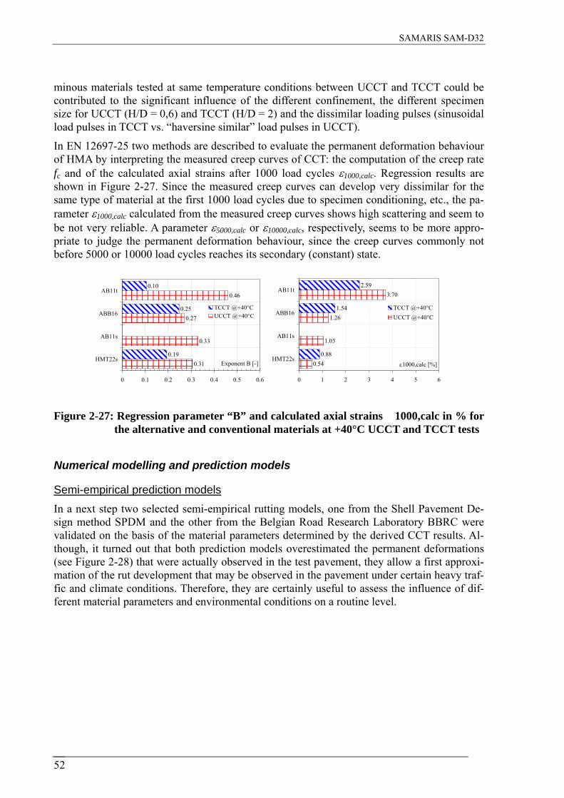
SAMARIS SAM-D32
minous materials tested at same temperature conditions between UCCT and TCCT could be contributed to the significant influence of the different confinement, the different specimen size for UCCT (H/D = 0,6) and TCCT (H/D = 2) and the dissimilar loading pulses (sinusoidal load pulses in TCCT vs. “haversine similar” load pulses in UCCT).
In EN 12697-25 two methods are described to evaluate the permanent deformation behaviour of HMA by interpreting the measured creep curves of CCT: the computation of the creep rate fc and of the calculated axial strains after 1000 load cycles ε1000,calc. Regression results are shown in Figure 2-27. Since the measured creep curves can develop very dissimilar for the same type of material at the first 1000 load cycles due to specimen conditioning, etc., the pa-rameter ε1000,calc calculated from the measured creep curves shows high scattering and seem to be not very reliable. A parameter ε5000,calc or ε10000,calc, respectively, seems to be more appro-priate to judge the permanent deformation behaviour, since the creep curves commonly not before 5000 or 10000 load cycles reaches its secondary (constant) state.
0.31
0.33
0.27
0.46
0.19
0.25
0.10
0 0.1 0.2 0.3 0.4 0.5 0.6
HMT22s
AB11s
ABB16
AB11t
Exponent B [-]
TCCT @+40°CUCCT @+40°C
0.54
1.03
1.26
3.70
0.88
1.54
2.59
0 1 2 3 4 5
HMT22s
AB11s
ABB16
AB11t
ε1000,calc [%]
6
TCCT @+40°CUCCT @+40°C
Figure 2-27: Regression parameter “B” and calculated axial strains 1000,calc in % for the alternative and conventional materials at +40°C UCCT and TCCT tests
Numerical modelling and prediction models
Semi-empirical prediction models In a next step two selected semi-empirical rutting models, one from the Shell Pavement De-sign method SPDM and the other from the Belgian Road Research Laboratory BBRC were validated on the basis of the material parameters determined by the derived CCT results. Al-though, it turned out that both prediction models overestimated the permanent deformations (see Figure 2-28) that were actually observed in the test pavement, they allow a first approxi-mation of the rut development that may be observed in the pavement under certain heavy traf-fic and climate conditions. Therefore, they are certainly useful to assess the influence of dif-ferent material parameters and environmental conditions on a routine level.
52

SAMARIS SAM-D32
0
5
10
15
20
25
30
0 20'000 40'000 60'000 80'000 100'000
load cycles n [-]
rut d
epth
[mm
]
SPDM rut depth prognosisALT-DART - dual wheel tires
ALT-LAVOC test site +40°C
0
5
10
15
20
25
30
0 20000 40000 60000 80000 100000
load cycles n [-]
rut d
epth
[mm
]
ALT-LAVOC super single tiresSPDM rut depth calculation
Figure 2-28: Permanent deformation results for the ALT-DART (left side) and ALT-LAVOC (right side) wheel tracking device – test data and predicted rut depth according to SPDM method on AB11s & HMT22s
Rheological models and finite element modelling In addition to the semi-empirical models rheological models for performance prediction on an advance level were evaluated. Such rheological models relate the applied stress history to ac-cumulated viscoelastic strains and thus take into account the viscoelastic response of HMA. Following six rheological models were selected and implemented in a Finite Element (FE) code: Burgers model, generalized Maxwell model, generalized Kelvin-Voight model, Power Law model, Huet model and the Huet-Sayegh model. Since the creep response is always a consequence of both, deviatoric and hydrostatic loading, in an advanced approach two creep-compliance functions, one associated with hydrostatic and one with deviatoric loading, were
-2.176e-07
1.859e-04
3.720e-04
5.582e-04
7.443e-04
9.304e-04
1.117e-03
1.303e-03
1.489e-03
1.675e-03
1.861e-03
-1.789e-04
-3.312e-05
1.127e-04
2.585e-04
4.043e-04
5.501e-04
6.960e-04
8.418e-04
9.876e-04
1.133e-03
1.279e-03
-3.711e-03
-3.340e-03
-2.970e-03
-2.599e-03
-2.228e-03
-1.857e-03
-1.486e-03
-1.115e-03
-7.440e-04
-3.731e-04
-2.204e-06
-2.502e-03
-2.251e-03
-2.001e-03
-1.751e-03
-1.501e-03
-1.251e-03
-1.001e-03
-7.505e-04
-5.003e-04
-2.502e-04
-1.926e-09
Figure 2-29: Strains in radial (upper line) and axial direction (lower line) for height/diameter-ratio of 63/100: (left) BC2 = friction @ Coulomb with =0,6 and (right) BC3 =1,0 (magnification factor of displacements = 50)
53

SAMARIS SAM-D32
-4.549e-07
2.087e-04
4.178e-04
6.270e-04
8.361e-04
1.045e-03
1.254e-03
1.464e-03
1.673e-03
1.882e-03
2.091e-03
-1.006e-04
1.127e-04
3.260e-04
5.393e-04
7.526e-04
9.659e-04
1.179e-03
1.392e-03
1.606e-03
1.819e-03
2.032e-03
-4.191e-03
-3.772e-03
-3.353e-03
-2.934e-03
-2.516e-03
-2.097e-03
-1.678e-03
-1.259e-03
-8.401e-04
-4.213e-04
-2.410e-06
-4.076e-03
-3.669e-03
-3.261e-03
-2.854e-03
-2.446e-03
-2.038e-03
-1.631e-03
-1.223e-03
-8.153e-04
-4.076e-04
-1.926e-09
Figure 2-30: Strain in radial (upper line) and axial direction (lower line) for height/ di-ameter-ratio of 200/100: (left) BC2 = friction @ Coulomb with =0,6 and (right) BC3 =1,0 (magnification factor of displacements = 50)
introduced, whereas each type of response can be described and simulated by different viscoe-lastic models.
Finally, the results of the material tests on HMA and the rheological models were used in nu-merical (FE) simulations to analyse the stress situation of both, CCTs with different height/diameter ratios and WTTs with the small size device and the large size device (see Figure 2-29 and Figure 2-30). The simulations showed that in CCT the restrained radial de-formation near the loading platen due to friction effects (BC2 or BC3 in Figure 2-29 and Figure 2-30 means boundary conditions between loading platen and specimen with small fric-tion µ=0,6 and fixed loading platen µ=1,0) can significantly affect the deformation of the whole specimen and therefore may lead to an underestimation of the permanent deformation behaviour (see Figure 2-29 and Figure 2-30). Thus, performance based requirements for per-manent deformation behaviour of HMA based on TCCT with a height/diameter ratio H/D < 2 shall not be permitted.
54

SAMARIS SAM-D32
-6.688e-03
-5.154e-03
-3.619e-03
-2.085e-03
-5.508e-04
9.835e-04
2.518e-03
4.052e-03
5.586e-03
7.121e-03
8.655e-03
-2.551e-02
-2.278e-02
-2.006e-02
-1.733e-02
-1.461e-02
-1.188e-02
-9.155e-03
-6.429e-03
-3.704e-03
-9.787e-04
1.747e-03
Figure 2-31: WTT with small device (WTT-SS) of HMT 22 asphalt: strains in horizontal and vertical direction at maximum load and T=+50 °C (air tempered)
-7.701e-03
-6.005e-03
-4.309e-03
-2.612e-03
-9.160e-04
7.803e-04
2.477e-03
4.173e-03
5.869e-03
7.566e-03
9.262e-03
-2.290e-02
-2.024e-02
-1.758e-02
-1.493e-02
-1.227e-02
-9.611e-03
-6.954e-03
-4.296e-03
-1.639e-03
1.018e-03
3.675e-03
Figure 2-32: WTT with large device (WTT-LS) of HMT22s asphalt: strain in horizontal and vertical direction for the maximum load and T= +50 °C (air tempered)
In regard to wheel tracking tests the analysis of the stress situation in specimens of the small WTT-SS (see Figure 2-31) and large WTT-LS device (see Figure 2-32) shows, that both stress distributions are qualitatively similar. However, the stress states resulting from the small WTT (WTT-SS) are about four times larger than the stress states obtained from the large device (WTT-LS). Especially, the high deviatoric stress states obtained from the small device, result-ing in stress-induced creep deformations, explain the experimentally-observed “cutting” of the asphalt specimen. In contrast to the stress states obtained from the WTT with large device (WTT-LS), the stress state and the respective creep deformations of the WTT with small de-vice (WTT-SS) do therefore not represent actual on-street loading/deformation conditions
55

SAMARIS SAM-D32
56

SAMARIS SAM-D32
2.8 Review of the road and other industry by-product use in road construction and rehabilitation in the Central and East European countries (D15)
Scope This summary report presents a brief review of the current state of the road and other industry by-product use in road construction and rehabilitation in the Central and Eastern European (CEE) countries. It summarizes the extent of the use of various by-product materials and re-cycling policies in these countries.
The report was prepared in the framework of the SAMARIS project by Working Group 6 (WP 6). The WP 6 developed a questionnaire for data collection that was similar to the OECD questionnaire used for the OECD report “Recycling strategies for roadwork” in 1997. This re-port provides the brief overview of data gathered by national reporters and summarizes some general conclusions and recommendations.
Reporting Countries The report was elaborated on the basis of responses to the WP 6 questionnaire provided by the following CEE countries:
1. Belarus (BY), 6. Romania (RO),
2. Bulgaria (BG), 7. Russia (RUS),
3. Czech Republic (CZ), 8. Slovakia (SK),
4. Hungary (HU), 9. Slovenia (SI),
5. Poland (PL), 10. Ukraine (UA).
This report was prepared by SAMARIS contractors at Brno University of Technology (TU Brno, CZ) and Road and Bridges Research Institute Warsaw (IBDiM, PL).
Data Collected The questionnaire consisted of three basic parts focused on (i) road by-products, (ii) industry by-products and (iii) promotion of recycling strategies.
A. Road by-products Data were collected for the following materials:
• Reclaimed Asphalt Pavement (RAP), • Reclaimed Concrete Pavement (RCP), • Reclaimed base and subbase materials, and • Mixed RAP, RCP and reclaimed base and sub-base.
Data on the annual quantity in tonnes and way of recycling (% of plant or on-site recycling, % stock and % landfill) were collected. Further information was collected on application (hot,
57

SAMARIS SAM-D32
cold recycling), treatment (crushing, grading), technical, economical and environmental back-ground.
B. Industry by-products From the industry by-products the use of the following by-products was investigated:
• Blast furnace slag, air cooled, • Blast furnace slag, ground granulated, • Steel slag, • Non-ferrous slag, • Foundry sand, • Coal fly ash, • Coal bottom ash, • Mine waste rock, • Municipal soil waste incinerator bottom ash, • Scrap tyres, • Waste glass, • Building demolition materials.
For industry (non-road) materials, the requested information concerned the extent of use (rated on a numerical scale: 4 = in general use, 3 = in limited use, 2 = considered a potential use, 1 = considered a questionable use, 0 = not used and should not be used) and various road applications (use for hot mixes, cold mixes, stabilized base courses, granular base courses, embankments, fills etc.). For material and application combinations currently in use, addi-tional information was requested on amounts, material tests and acceptance criteria, construc-tion equipment and procedures, quality control tests, standard specifications and factors used in evaluating environmental and economic suitability.
C. Strategies promoting recycling Ten groups of questions were put together to gain insight into strategies used by each country to encourage recycling as the general policy, responsibilities of various parties, market parties involved, instruments promoting recycling, requirements for acceptation of by-products, ob-structions and transfer of knowledge.
Results of the survey The following observations summarize results obtained from CEE 10 countries:
A. Road by-products Reclaimed asphalt pavements: 9 countries responded out of 10 (9/10): Most of the RAP is in situ recycled – approx. 40 %, 30 % is deposited in stock, and 20 % is recycled in plant.
58

SAMARIS SAM-D32
Reclaimed concrete pavements: 4/10 countries :Most of RCP is recycled in plant, the rest in situ.
Table 2-4: Amount of Reclaimed Asphalt Pavement (RAP) and Reclaimed Concrete-Pavement (RCP) in the CEE countries (in kilo tonnes per year and % of re-cycling)
Reclaimed Concrete Pavement
(RCP)
--- - ---40-- Landfill %
--- - 15--15-- Stock %
--- - 85-50--- In situ recycling %
--- - -1005045-- Plant recycling %
--- - 100200510-- RCP/year (kt)
-530 50 5--10-- Landfill %
861530 - 15-6520-- Stock %
11-40 50 30801550100- In situ recycling %
380- - 50202020-- Plant recycling %
3551030 22 300140506903-RAP/year (kt) Reclaimed Asphalt
Pavement (RAP)
UASISK RU RO PLHUCZBGBYApplication Product
Conclusions:
• Recycling techniques are known. • Better situation was found in the Central European than in the East European countries. • In some countries only one type of recycling method is used. • Often there are no appropriate specifications for recycling. • Road authorities are not well informed and mistrustful regarding new technologies. • New technologies are being introduced rather by private companies (trial sections).
B. Industry by-products Mostly used industry by-products in the CEE-countries are:
Blast furnace slag, steel slag
Use: granular or stabilized base courses, backfills, embankments.
Coal fly ash
Use: embankments, stabilized base courses.
59

SAMARIS SAM-D32
Mining waste rock
Use: embankments, landscaping, backfills.
Conclusions: • Only few industry by-products are used in a greater extent. • The recycling of other by-products than slag, fly ash, or mining waste rock is almost
unknown. • There is a lack of funds for research into new technologies. • There is a lack of interest from the road authorities.
General conclusions and recommendations General conclusions based on the answers from particular countries:
• Recycling is concentrated only on few technologies. • No general policy of governments regarding recycling is carried out. • There are small financial sources for research. • There is lack of technical specifications. • There is only limited transfer of know-how.
How to improve the situation:
• Sharing more information. • Organization of seminars and lectures on recycling. • Coordination and involving of all market parties into the recycling process. • Catalogues of by-products and recycling techniques. • Support of research in CEE countries • Involving CEE countries into Common European projects.
The support of recycling can create additional benefits:
• Reduction of the cost of building materials. • Reduction of energy consumption. • Protection of mineral resources. • Cost reduction of transport of materials. • Environmental protection (decreasing quantity of storage of by-products). • New market opportunities for parties possessing relevant know-how.
60

SAMARIS SAM-D32
2.9 Technical guide for recycling techniques in road construction (D29)
Introduction Within the pavement stream of the SAMARIS project, the objective of Work Package 6 “Techniques for Recycling” was to provide updated information and recommendations about recycling techniques and applications on road pavements materials.
This report, formally referred to as deliverable D29 “Guide on Techniques for Recycling in Pavement Structures” of the SAMARIS project, is one of the four resulting documents in Work Package 6. It represents the most important outcome in Task 6.1 “Elaboration of a tech-nical guide on recycling techniques”. The starting point for the preparation of this report was Deliverable D5, “Literature Review of Recycling of By-products in Road Construction in Europe”, complemented with the information included in Deliverable D12 “Recommenda-tions for mixing plants for recycling works”.
The report has been developed by CEDEX with the collaboration of EUROVIA and TU Brno and the feedback received from partners of the consortium. It represents a literature review and know-how gathering on the use of recycled materials in road construction in Europe.
General structure The information collected during the literature analysis for the elaboration of the report fo-cused on guidelines concerning the potential use of recycled materials in the European road sector. The work included a thorough review of key pieces of literature in the subject that was completed with a review of documents and gathering of know-how from a set of countries, organizations and SAMARIS working groups.
As a consequence of all this work, it was decided that the Guide included in this report was to be structured as a collection of digests with technical information referring to the recycling of the following eleven secondary materials, which were considered the most representative, in road construction:
1. Colliery spoil / Mining waste rock
2. Air cooled blast furnace slag, air cooled
3. Ground granulated blast furnace slag
4. Steel slag (basic oxygen and electric arc furnace slag)
5. Coal fly ash
6. Coal bottom ash
7. Building demolished by-products
8. Municipal solid waste incinerator ash
9. Scrap tyres
10. Waste glass
11. Foundry sand
61

SAMARIS SAM-D32
Materials from recycling of bituminous pavement, for which the techniques and details have been deeply covered by PIARC working groups, are not included in this report.
Materials from concrete pavement recycling have been incorporated under the “building de-molished by-products” chapter.
For every material, the information has mostly been structured in the following chapters: 1. Origin 2. Recycling
2.1. Properties of the waste material or by-product 2.1.1. Physical 2.1.2. Chemical
2.2. Recycling process 2.2.1. Description 2.2.2. Quality control of the process
2.3. Properties of the recycled material 2.3.1. Physical 2.3.2. Chemical
3. Uses in road construction 3.1. Uses 3.2. Special considerations on design and construction 3.3. Quality control of the construction process 3.4. Examples or references of uses
4. Environmental issues 4.1. In the origin 4.2. In the recycling 4.3. In the use
5. Technical standards, specifications or guidelines by country 6. Technical references
A brief summary example of one of the digests: Municipal solid waste incinerator bottom ash As an example of the content of D29, “Guide on Techniques for Recycling in Pavement Structures”, a brief summary of the digest on “Municipal Solid Waste Incinerator Bottom Ash” is next included
Origin Municipal solid waste (MSW), fresh or resulting from previous treatment, can be used as combustion products in one or several incinerator lanes. The combustion of the MSW in the interior of the incinerator is almost complete, reducing an average of a 90% of the initial vol-ume and 70% of the initial weight (IADE, 1996). Three different types of incinerator furnaces can be distinguished: grill furnace, fluid bed furnace and rotation furnace.
During the incineration process, several types of by-products are generated: slag or bottom ash (waste materials made of partial or totally burned MSW) and fly ash (waste materials made of tiny particles that are dragged by the air streams out of the combustion chamber) (SAMARIS D5, 2004).
62

SAMARIS SAM-D32
B
A
Figure 2-33: A : Fresh bottom ash – B : Processed bottom ash
Recycling Before or during the natural weathering or ageing setting, the bottom ash has to be processed before being used in road construction. The process can be resumed as follow:
• Bottom ash or slag cooling in water immediately after the incineration process. • Magnetic process to eliminate ferrous (two stage of magnetic separator). • Removal of non ferrous particles (Eddy current machine). • Sieving (20mm to 40 mm). • Bottom ash stock in an outdoor during several months (between 1 and 6 months) to
obtain a chemical stability and reduce pH level of the material and leaching of metals.
After this process, the bottom ash can be treated with hydraulic binder for several reasons: • Reduce leaching (stabilization of bottom ash after weathering). • Control moisture content and bearing capacity (1 to 5 % of hydraulic binder). • Develop tensile strength in order to use in base or foundation courses (5 to 10 % of
cement).
Foam bitumen treatment can also be used to increase the mechanical properties in case of base course.
63

SAMARIS SAM-D32
The bottom ash is managed in monthly batch-processes to ensure traceability (origin and date of production). Each batch is handled in an installation like those in Figures 1 and 2 (SAMARIS D12, 2004).
To prevent underground water pollution from fresh bottom ash leachates the stockpiled area must be waterproofed.
The production of aggregates from incineration bottom ash requires a quality control starting in the furnace and ending with the measurement of the environmental properties of the proc-essed product.
Uses in road construction Subgrades
Uses in road embankment and capping layer are the most common applications.
Granular bases and sub-bases and stabilized bases
Processed bottom ash is assimilated to a non-treated gravel (Standard EN 13285), after treat-ment with cement (4 to 10 %) the mix is assimilated to a treated sand or gravel (Standard EN 14227).
Asphalt concrete
Because of the natural moisture content and composition, the bottom ash is only used for cold bitumen treatment: foam bitumen treated base or sub-base courses.
In the UK, incinerated refuse from a number of different incinerators was analysed. Most of the ashes were found to be suitable for use as bulk fill and some could have been suitable for use as the UK Type 2 granular sub-base (ROE, P. G., 1976) (SAMARIS D7, 2004).
The specific composition of the material usually leads to apply the following precautions of usage: The bottom ashes are not used in surface courses and must be overlaid by a layer of 15 cm
minimum thickness to avoid the deformations due to the oxidation of the residual alumin-ium particles.
They must be used far from sensitive environmental zones (examples: drinking water col-lecting area, river, highest ground water level, etc.).
Figure 2-34 (below): Photos of an outdoor installation for processing reclaimed asphalt concrete
64

SAMARIS SAM-D32
Processed 0/30
T17
T8
T19
T11
S12
unburned Primary Iron
Secondary iron
0/5
5/30
S9
NFS14
T4
>30
0/30
MSWI
Bottom ash
T2T16
S3OB15Crusher20 WT18
MP 7
OB 5
>30 mm
S21
T13
T6
Control sta-tion
Non ferrous metal
H1
Equipment : Input flow : about 50t/h
H1 : conveyer belt feeder
S3 : « star » screen 30mm BACKERS
T2, T6, T8, T13, T16, T17, T19 : conveyor belt
T4, T11 : « sand » conveyer belt
OB 5 & 15: Over-band , iron separator primary and secon-dary ANDRIN
Wind tunnel 18 : unburned materials separator
Crusher 20 : HAZEMAG
S21 : screen # 200 mm
MP7 : third iron separator ANDRIN
S9 : « star » screen 8 mm BACKERS
NFS14 : Non Ferrous separator ANDRIN
S12 : output conveyor
Figur 2-35 (above): Examples of synoptic of fixed recycling plant
65

SAMARIS SAM-D32
Environmental issues The European status of MSWI bottom ash is that of a non-inert waste, a secondary raw mate-rial, and it can be considered as hazardous if it contains hazardous components.
During the recycling process a set of hazardous characteristics of this material should be taken into consideration due to their impact both in the manipulation and recycling process it-self and in the later use in road construction. These hazardous characteristics are mostly chemical properties which refer, in each case, to a certain concentration in an eluate. Table 1 ”Decisive hazardous characteristics for Municipal Solid Waste Incinerator Bottom Ash” summarizes this, marking with “*” those components of every product that are considered hazardous and for which, as a consequence, particular testing should be undertaken during the recycling process before choosing a final application of the waste material. This table does not include any threshold values, because they are very dependant on the test method used, which is not the same in all European countries surveyed within the SAMARIS project, as well as the requirements (SAMARIS D16 and D24, 2005).
PH-VALUE * CYANIDE * VANADIUM ZINC * CADMIUM *
ELECTRIC CONDUCTIVITY
* DOC * CHROMIUM TOTAL * ARSENIC * ANTIMONY *
CHLORIDE * BORON NICKEL * SELENIUM BARIUM
SULPHATE * ALUMINIUM * KOPER * MOLYBDENU
M * LEAD *
2.1: Decisive hazardous characteristics for MSWI bottom ash
Most of the MSWI bottom ash environmental control is achieved using leaching tests and or-ganics content tests. The European standard mostly used is EN 12457-2 Leaching, a compli-ance test for leaching of granular waste materials and sludge.
Technical standards, specifications or guidelines by country The digest on MSWI bottom ash includes references to documents related to the environ-mental assessment of this material, mainly from Denmark, France and Germany.
As an example the list of documents from Germany is shown below:
Germany • RuA-StB 01. Richtlinien für die umweltvertverträgliche Anwendung von industriellen Ne-
benprodukten und Recycling-Baustoffem im Strassenbau. Guidelines for the environmen-tally compatible use of industrial by-products and RC building materials in road construc-tion. Forschungsgesellschaft für Strassen- und Verkehrswesen. 2001.
• TL Gestein-StB 04. Technische Lieferbedingungen für Gesteinskörnungen im Straßenbau. Technical Terms of Delivery for aggregates in road construction. Forschungsgesellschaft für Strassen- und Verkehrswesen. 2004.
66

SAMARIS SAM-D32
• M HMVA. Merkblatt über die Verwendung von Hausmüllverbrennungsasche im Straßen-bau. Bulletin for the use of ash from the incineration of domestic waste in road construc-tion. Forschungsgesellschaft für Straßen - und Verkehrswesen. 2005.
References In this separate chapter a list of thirty technical references are included.
67

SAMARIS SAM-D32
3. THE STRUCTURES STREAM OF RESEARCH
3.1 Overview and introduction
Maintenance of concrete structures, whether it is preventive or for repair or strengthening, is a heavy burden for society not only in financial terms but also due to its risk of causing major and longer-term disturbance of traffic. A key objective of the Structures stream of the SAMARIS project was to support the EU sustainability policy by providing tools and meth-ods that would a) enhance structural assessment methods to avoid unnecessary interventions on highway structures and b) radically improve efficiency and durability of repair methods. Both will reduce the numbers of necessary road closures and resulting detours which will lead to substantial reduction of total repair costs and will have favourable mobility and safety im-plications. Special attention was given to the New Member States where condition of the highway structures is falling behind the situation in the EU 15 countries.
The structures part of the project had the following technical and scientific objectives:
1. To draw together the requirements for a sustainable maintenance strategy that satisfies the functional, safety, economic and environmental requirements for highway structures.
2. To investigate the applicability of two innovative techniques, 1) the surface applied corro-sion inhibitors (CI) and 2) the Ultra High Performance Fibre Reinforced Concrete (UHPFRC), for maintenance of highway structures.
3. To update and analyse the inventory of highway structures in some EEA and CE countries and to propose methods and procedures for improved maintenance of highway structures.
The entire project was end-user oriented and has produced a number of deliverables to en-courage using of innovative rehabilitation techniques, such as implementation of CI and UHPFRC, and using of modern structural assessment techniques to optimise management of existing highway structures. Different documents were developed for the use of new materials and to optimise bridge inspection, traffic load modelling and higher levels of assessment.
The topics were divided into four work packages: • WP 12 – Strategies for rehabilitation of highway structures, • WP 13 – Corrosion inhibitors, • WP 14 – UHPFRC materials and • WP 15 – Survey.
WP 12 – Strategies for rehabilitation of highway structures has drawn together the require-ments for a sustainable maintenance strategy for highway structures presented in the deliverable D31 Guidelines for the use of innovative materials and techniques within this strategy.
The document is intended for the bridge owners who must often select an appropriate reha-bilitation measure from a number of maintenance options for a structure, ranging from a ‘do nothing’ option in the short term to major structural repairs or even replacement of the bridge. Yet, selecting the most cost effective repair strategy is difficult as each particular option may
68

SAMARIS SAM-D32
use different repair techniques and require maintenance work to be undertaken at different times within the lifetime of the structure. Thus a method of making a fair comparison between competing and often quite different repair options is required.
The D31 provides a structured approach to deciding on an optimum repair strategy for an in-dividual structure, and how this can be assessed against the needs of the network as a whole. It outlines the reasons for the deterioration of reinforced concrete bridges, how such deteriora-tion is detected and assessed, the various approaches available for deciding on an optimum rehabilitation strategy, and gives a recommended approach. It deals specifically with the ad-ditional considerations necessary when innovative techniques (those without an established track record) are used. It concentrates on the decision making procedures rather than any de-tailed technical description of alternative repair techniques; these are available elsewhere. The D31 report covers the following topics:
• deterioration of concrete bridges, • detection and assessment of deterioration, • selection of maintenance option, • choice of the optimum maintenance strategy, • recommended approach to choosing a maintenance strategy: structured engineering
judgement and • implementation.
WP 13 – Corrosion inhibitors has investigated the effects and effectiveness of a family of these materials (amino-alcohols) when surface applied (painted or sprayed) and has produced specifications for their characterisation, use and methods of applications.
Surface-applied corrosion inhibitors are applied to the mature hardened concrete surface dur-ing rehabilitation procedures and diffuse through the cover concrete. Inhibitor action is typi-cally to act as a barrier to newly arriving chlorides unless the concentration of chlorides be-comes too high for the barrier to remain effective. Before the SAMARIS project, experiences with these materials were very diverse, from “showing good efficiency” to “not working at all”. Experiments in SAMARIS showed that the inhibitors are best used:
• to extend (or help to achieve) the required service life by deferring the initial time to depassivation and/or
• through reducing the rate of corrosion once corrosion is propagated or • retard incipient action.
The conclusion of the research was that surface applied corrosion inhibitors cannot totally stop corrosion, but under certain conditions they ‘buy time’ by extending the time to first re-pair or next significant maintenance intervention. Time is also important. Applying it before the propagation of corrosion is significantly advanced, as part of a proactive preventative maintenance strategy program, seems to be the optimal technique.
WP 13 has produced several reports. The D17 “Report on test of effectiveness of corrosion inhibitors in laboratory trials - parts A and B” was of an internal nature and used as the basis for informing the debate on optimal use and guidance to specifiers . The main deliverables were D21 “Report on test of effectiveness of corrosion inhibitors in field trials” and “D25a - Specifications for the use of corrosion inhibitors for the rehabilitation of concrete highway structures” are of a public nature. The later one is the most important deliverable of this work package and covers the following topics:
69

SAMARIS SAM-D32
• context for use - a structured engineering judgement maintenance strategy, • initial assessment, • preview study option, • full scale maintenance intervention, • post-repair monitoring option and • summary flowchart.
The most important conclusion of the work was that surface applied corrosion inhibitors work under special conditions, which exclude combinations of high chloride contamination of con-crete and advanced stages of corrosion of reinforcement. Therefore, their use in highway structures is optimal in the context of proactive maintenance interventions rather than reactive rehabilitation of advanced deterioration on structures.
WP 14 – UHPFRC materials has developed and successfully demonstrated the applicability and advantages of Ultra High Performance Fibre Reinforced Concrete, has optimised it for maintenance and provided specifications for its use.
Experience from some other recent studies (CONREPNET – Concrete Repair Network, http://projects.bre.co.uk/conrepnet/) shows that life-time of the conventional repair methods with cement-based materials is unsatisfactorily short. 25% of interventions fail in the first 5 years and 75% in the first 10 years after they were applied. The cementitious materials incor-porating fibres, in particular the UHPFRC that is characterized by a very low water/binder ra-tio and high fibre content, are turning as a possible efficient solution of this problem. They provide the structural engineer with a unique combination of excellent rheological properties in the fresh state, extremely low permeability and high strength and tensile strain hardening in the range of the yield strain of construction steel (up to 0.2 %).
The main objectives of WP 14 were to: • demonstrate the applicability and advantages of ultra compact HPFRCC materials for
the rehabilitation of concrete structures, particularly bridges, • make the first step towards the optimization of these materials for maintenance and to • provide specifications for the use of these materials and their further optimization.
To achieve these objectives, the WP14 has produced the following reports: • D13 “Report on preliminary studies for the use of UHPFRC for rehabilitation of road
infrastructure components”, • D18 “Report on tests of UHPFRC in the laboratory” - parts A and B, • D22 “Full scale application of UHPFRC for the rehabilitation of bridges – from the lab
to the field”, • D25b “Specifications for the use of UHPFRC for the rehabilitation of concrete highway
structures” and • D26 “Modelling of UHPFRC in composite structures”.
Of those, the two most important reports are D22 and D25b.
D22 gives an overview of the conceptual approach, and provides detailed information on the first application performed during the project SAMARIS, in view of the application of UHPFRC for the rehabilitation of reinforced concrete structures. It focuses on the extremely
70

SAMARIS SAM-D32
low permeability of UHPFRC which, associated with their outstanding mechanical properties, can locally "harden" reinforced concrete structures in critical zones subjected to an aggressive environment and to significant mechanical stresses. Composite UHPFRC structures promise a long-term durability to help avoiding multiple interventions on structures during their service life. UHPFRC materials can be applied on new or on existing structures as thin watertight overlays in replacement of waterproofing membranes, as reinforcement layers combined with reinforcement bars, or as prefabricated elements such as kerbs.
D25b gives practical and conceptual recommendations for the application of UHPFRC for the rehabilitation of reinforced concrete structures. It is primarily intended as a practical tool to help engineers and owners answering the following questions:
• Are UHPFRC adapted for my case? • What can I expect from UHPFRC? • How do UHPFRC compare with other materials? • How to classify my structure in terms of degree of restraint? • Which level of UHPFRC performance is needed for my case? • How can I take UHPFRC into consideration for design? • How to verify the properties of UHPFRC? • How to produce and process UHPFRC cast on site?
Furthermore, the D25 has worked on the concept of application, classification of applications (prefabrication of new elements, such as kerbs or cast-in place UHPFRC) and has presented requirements, based on CEMTECmultiscale® material tested in SAMARIS. This material is made of pure Portland cement and has high quantity of steel fibres which provide outstanding protective function, no localized macrocracks at minimum fibre dosage of 1.5 % volume. Further research will be needed to extend this table to other types of UHPFRC with different kinds of binders and fibrous mixes.
WP 15 – Survey provided an up-to-date inventory of highway structures in selected in CE (Central European) and EEA (European Economic Area) countries, including a review of cur-rent procedures for determining condition, loading and structural safety (Deliverable D19), and Guidance for optimised assessment of highway structures (Deliverable D30).
D19 brings an overview about the status of the road network in Austria, Czech Republic, Hungary, Poland, Norway and Slovenia. Information includes figures about the length of the road networks and number and characteristics of different types of highway structures (bridges, culverts, tunnels, retaining walls). Then it summarises the methods used in these and some other countries for assessment of condition of the structures, for traffic loading (empha-sising the important differences among them) and for structural safety. Compared to EU-15 countries, the New Member States clearly build a lot of new roads, especially motorways. Therefore, proportion of newer highway structures there is much higher than in Austria in Norway, which experienced similar “boom” around 20 years ago. Otherwise, except for dif-ferences clearly related to the landscape (for example, high proportion of tunnels in Austria and Norway and Slovenia) most of the other answers drive into similar directions (with some time shift in some cases).
Every bridge administrator, in every country, has created or adopted a system for managing bridge stock. All systems have common roots and similar rules. However, the systems are in-coherent; they take similar factors under consideration, but present different outcomes.
71

SAMARIS SAM-D32
Truck weights throughout Europe vary considerably. The main reason is a great variation in policies of collection of truck weight statistics (from no to comprehensive networks) and in overload enforcement policies and activities (from almost no to several thousand Euro fines). For a given bridge capacity, the differences in real traffic loading means that there is a signifi-cantly greater safety margin in some countries than others. Consequently, many bridges can function safely without being strengthened or replaced because the traffic loading is consid-erably less than on others. European countries with a huge stock of highway bridges, as France, Germany, Italy, Poland and Spain, do not use specific procedures for safety assessment of existing highway bridges and, in general, the basis for the assessment is the same as for the design of new bridges. Other countries do use optimised safety assessment procedures but only a few (United King-dom, Scandinavian countries) have special codes for it. D30, Guidance for optimised assessment of highway structures, was focusing on optimised bridge management through improved bridge inspection, more accurate static and dynamic traffic load measurement and modelling and by applying calibrated structural models and real site data to achieve much more accurate assessment. The document was prepared as a guid-ance document which advises on ways to assess bridges with optimised tools, by taking ad-vantage of information from bridge inspections, site measurements and in some cases load tests. Several examples are included to illustrate the benefits of the procedures proposed. The most significant improvements on the present knowledge were achieved in the area of op-timised safety assessment through updating of the structural models by load testing and by applying realistic traffic loading. Load tests are very popular in some countries but not used at all in others. A comprehensive overview about these methods is given, showing potential benefits but also constraints of their application. In addition, a novel soft load testing proce-dure was introduced, which captures important bridge characteristics (influence lines and dis-tribution of traffic loading among different structural members) from the normal traffic flow, thus avoiding traffic closures required during the traditional proof and diagnostic load tests. The chapter on realistic loading deals with static and dynamic component of traffic loading. A clear conclusion of the static part of the analysis, based on weigh-in-motion (WIM) data, is that applying the same traffic loading rules across Europe and without accounting for the type of the road, can be extremely conservative. Two ways of assessing a site traffic load model are presented, with Monte Carlo simulation and as calibrated notional load models, the first one being more accurate but complex and the other one easier to implement by the end users. Dy-namic modelling of bridges in the past has often shown that dynamic amplifications of traffic loading due to the passing heavy vehicles are generally lower than those prescribed in differ-ent codes and standards. Applying such conservative Dynamic Amplification Factors (DAF’s) is beneficial during the design of a bridge, but in the bridge assessment stage they may result in unrealistically high load effect estimates and, consequently, unnecessary remediation or re-placement of the bridge. An elaborate statistical technique was developed for the calculation of characteristic DAF and is illustrated by example in the report. For the sample bridge used for this work, the dynamic factor required was found to be just 6%, considerably less that it would be required in a design code. These results were confirmed by an experiment which applied the new generation of bridge weigh-in-motion system, to measure for the first time ever the DAF for all loading events on the bridge due to the running traffic. In addition to showing great reduction of DAF as a function of vehicles’ weight, the results also demon-strated how smoothness of the pavement influences the DAF.
72

SAMARIS SAM-D32
&&&
More comprehensive information about the outcomes of the Structures stream of the SAMARIS report is available in the executive summaries of the most important deliverables in the following chapters of this report and in the full documents that can be downloaded from http://samaris.zag.si/.
73

SAMARIS SAM-D32
74

SAMARIS SAM-D32
3.2 State-of-the-art report on assessment of structures in selected EEA and CE countries (D19)
This report summarises different condition and the structural safety assessment methods for the highway structures developed worldwide, but with the main focus on European countries.
The condition assessment (CA) is the process where, starting from the results of the inspec-tion, the final result is the determination of the functional capability and the physical condi-tion of bridge components, including the extent of deterioration and other defects. The condi-tion assessment can be either qualitative, in the form of definition of classes, or quantitative, in the form of a so-called “condition rating”, a value that indicates the global state of conser-vation of the bridges and their ranking according to its value.
The structural safety assessment is the process where, starting from the actual resistance of the structure (updated with the results of the inspection and testing) and the actual loading, the remaining safety (measured in terms of partial safety factors, reliability index, probability of failure or similar) is derived. This report presents a literature review of the methods applied in different countries or proposed by several International Bodies.
Report covers the following technical chapters: • Survey of the questionnaires, with summary of answers provided by six subcontractors, • Condition Assessment, with an overview of the procedures used in 12 countries, • Loading, indicating the differences in traffic loading around Europe and • Structural Safety, with an overview of the procedures used in 8 countries.
Survey of the questionnaires The report starts with a survey on the assessment procedures used in selected CE (Central European) and EEA (European Economic Area) countries. This was accomplished from an-swers to the questionnaire, which was sent to six of these countries (Austria, Czech Republic, Hungary, Norway, Poland and Slovenia), and through extensive study of existing policies and literature. Chapters of the report summarise information on road system, bridges, culverts, tunnels, retaining walls, traffic loading and structural safety.
Particularly in the view of comparison of the New Member States (NMS) Czech Republic, Hungary, Poland and Slovenia on one side and other countries (Austria and Norway) on the other side, it was clear that in order to reduce the gap between the level of road infrastructure in the NMS and the Western European countries, the NMS build a lot of new roads and new structures. Therefore, proportion of newer highway structures there is much higher than in Austria in Norway, which experienced similar “boom” around 20 years ago. Other differences between NMS and other countries are less distinct. Except for those clearly related to land-scape (for example, high proportion of tunnels in Austria and Norway and Slovenia), most of the other answers drive into similar directions, with some time delay in some cases:
1. For all countries the most advanced information is available for bridges, then for tun-nels. Culverts and retaining walls are a big unknown all around Europe.
2. All countries use a more or less established Bridge Management Systems (BMS), but decisions are primarily based on structural condition and much less on structural safety.
75

SAMARIS SAM-D32
3. Only Norway and Hungary use BMS for economic aspects of bridge management.
4. Knowledge about real traffic loading is very diverse from one country to another. Al-though most countries have weigh-in-motion system to traffic collect data is, with the exception of Slovenia, not used to optimise structural assessment.
5. Control of overloaded vehicles is weak, which has negative impact on assessment of structures.
Condition assessment Condition assessment provides the owner or responsible authorities for the maintenance of highway structures with the appraisal of the present situation of the structures. Assessment gives data about the intensity and extent of observed defects on the structures, the cause for these defects and possible deterioration processes and impact of such findings to the safety and service life of the structures. These data are the basis for the estimation of possible inter-vention and for rough estimation of costs for possible remedial work.
Often the deterioration processes have several causes and are difficult to explain. Only when the source of problems is well defined and understood, reliable rehabilitation techniques can be proposed and executed. Usually, each defect can be addressed by several types of rehabili-tation techniques which depend on the technological possibilities, on the users’ safety re-quirements, on service life of the structure, on operational requirements during repair (lanes closed, closing of the structure, weather conditions, etc.) and on available financial resources.
Therefore, the main objectives of the condition assessment are to: • detect possible deterioration processes, • indicate the condition of the structure, its elements and the entire highway structures’
stock, • rank the structure for urgent repair and maintenance strategies, • optimise the maintenance budget allocation.
Discussed in the report are also: • procedures for condition assessment (inspections – superficial, regular, main and de-
tailed, catalogue of definitions and descriptions of defects and methods for quantifica-tion of the defects),
• phases of condition assessment (in situ and evaluation of results), • proposals from international bodies and organizations, such as project BRIME from the
EU 4th Framework Programme, COST action 345 and PIARC (World Road Association) committees and
• review of condition assessment procedures in twelve selected countries.
The analysis shows that every bridge administrator, in every country, has created or adopted a system for managing bridge stock, which incorporates condition assessment of structures. All systems have common roots and similar rules. However, the systems are incoherent; they take similar factors under consideration, but present different outcomes.
76

SAMARIS SAM-D32
Loading Truck weights throughout Europe vary considerably. The main reason is a great variation in policies of collection of truck weight statistics (from no to comprehensive networks) and in overload enforcement policies and activities (from almost no fines to several thousand Euro fines).
For a given bridge capacity, the differences in real traffic loading means that there is a signifi-cantly greater safety margin in some countries than others. Bridges throughout Europe are as-sessed using a range of techniques and load models. When a bridge is strengthened or re-placed, then it should be designed for full Eurocode loading which allows for future traffic growth. However, there are many bridges which can function safely without being strength-ened or replaced because the traffic loading is considerably less than in others. Such approach to bridge assessment can prevent a great deal of unnecessary strengthening and replacements.
To maximise savings in infrastructure rehabilitation and replacement costs, continent-wide, it is recommended that:
• a European Bridge Assessment code, with allowances for region-specific loading data, is developed;
• all regions collect truck weight data in order to ascertain if there is an overload problem or not and to determine region-specific variations in the load model for assessment;
• a policy of overload enforcement is developed which can handle multi-national traffic through many jurisdictions;
• research is carried out on the financial implications of best- and worst-practice en-forcement policies as it seems likely that a great deal of money is being wasted through in adequate overload enforcement in some countries.
Structural Safety European countries with a huge stock of highway bridges, as France, Germany, Italy, Poland and Spain, do not use specific procedures for safety assessment of existing highway bridges and, in general, the basis for the assessment is the same as for the design of new bridges. In France, some reduction in partial safety coefficients for materials or dead loads is possible but without official rules on how to do it. A similar situation exists in Spain. In Germany, no re-duction is permitted in the specified safety levels for assessment compared with design.
An important factor is the definition and calculation of the so-called condition factor. For ex-ample, in the UK it is used to account for any deficiencies that are noted in the inspection but cannot be allowed for in the determination of the calculated resistance. The numerical value (always less than 1.0) is based on engineering judgement and takes into account any defi-ciency in the integrity of the structure detected during the inspection. The condition factor in USA accounts for the increased uncertainty in the resistance of deteriorated members and the likely increased future deterioration of these members during the period between inspection cycles. Slovenia and USA are the only countries where the condition rating is directly used (via a table in the case of USA and via an equation in the case of Slovenia) to estimate the remaining structural capacity of a deteriorated structure. Also discussed in the report are dif-ferent assessment philosophies and methods behind the Codes, from the target reliability indi-ces to partial safety factors, the concepts redundancy and of system behaviour.
77

SAMARIS SAM-D32
Slovenia, USA and UK are using the concept of condition factor. In UK some guidance is given on how to obtain this factor in the case of masonry arch bridges. Also specific standards are developed for specific deterioration processes (steel corrosion, alkali-silica reaction, fa-tigue of corroded reinforcing bars) giving general guidelines for the assessment of highway structures affected by those damages. However, the general rule is to use the engineering judgement and there is no direct relation between the condition rating as derived from the in-spection process and the condition factor. In USA there is a direct link between condition rat-ing and condition factor. In Slovenia the concept of capacity reduction factor is used and ob-tained with an equation where the condition rating, the target reliability index and the coeffi-cient of variation of the resistance are considered. In the Czech Republic some guidance is given in the reduction of the total allowed traffic load in the bridge taking into account the condition class of the bridge.
Results of the surveys presented in this report were used for preparation of another deliver-able of the SAMARIS project, the D30 – Guidance for the optimal assessment of highway structures.
78

SAMARIS SAM-D32
3.3 Guidance on optimized assessment of highway structures (D30)
Maintenance of concrete structures is a heavy burden for society, both in financial terms and as it causes major and longer-term disturbance of traffic. The SAMARIS project has ad-dressed this problem in two ways:
• through investigation and improved maintenance of highway structures using greatly enhanced repair methods on the one side and
• by proposing improved methods and procedures for the assessment of highway struc-tures; here special attention was given to the New Member States and other Central European countries where the condition of highway structures has fallen behind the situation in Western European countries.
This report, produced by the members of work package 15, is focusing on optimised bridge management through improved bridge inspection, more accurate static and dynamic traffic load measurement and modelling and by applying calibrated structural models and real site data to achieve much more accurate assessment. Accurate assessment results in substantial savings in funds and natural resources by preventing the premature remediation of structures that are still safe and serviceable.
As the topic is very wide, the authors had no ambition to prepare specifications or codes of practice. Instead, this document should be seen as a guidance document. Rather than strictly applying the design rules, it advises on ways to assess bridges with optimised tools that take advantage of information from bridge inspections, site measurements and in some cases load tests. Several examples are included to illustrate the benefits of the procedures proposed.
The report is divided into two major chapters: on condition and on safety assessment. The first gives an overview of the existing procedures and addresses the most important issues as-sociated with efficient bridge inspection. The second focuses on the optimisation of safety as-sessment through evaluation of realistic carrying capacity and live (traffic) load effects. In both cases, significant improvements on the present knowledge were achieved.
Condition assessment Condition assessment (CA) of highway structures provides the owner or responsible authori-ties for the maintenance of highway structures with an appraisal of the present situation for the structures. Assessment gives data about the intensity and extent of observed defects in the structures, the cause for these defects and possible deterioration processes and the impact of such findings on the safety and service life of the structures. This data forms the basis for planning of possible interventions and for a rough estimation of costs for possible remedial work. This information is crucial as it is used for the prioritization of remediation work and achieving the best use of limited resources.
Unfortunately, condition assessment is not always an easy task. Deterioration processes may have several causes and it is difficult to find simple explanations and understanding of the problems. Usually, for each defect, several types of possible remedial options can be proposed which depend on the technological possibilities as well as on the requirements for the users' safety, service life of the structure, operational requirements during repair (lane closures, clos-ing of the structure, weather conditions, etc.) and available funds.
79

SAMARIS SAM-D32
The main objectives of condition assessment are to: • detect possible deterioration processes, • reveal the condition of structures and their elements, individually and as part of the en-
tire highway network structures’ stock, • rank the structures for urgency of repair and maintenance strategies, • optimise the maintenance budget allocation.
Further issues discussed in the report are: • catalogue of defects, • training of inspectors, • health and safety issues for inspectors, • suitable equipment for inspectors, • range of available investigation, • safe and long-term data storage (writ-
ten documentation, computers, soft-ware) and
• quality control of condition assess-ment.
One of the main deliverables of this part of the projects is the Internet based catalogue of defects (http://defects.zag.si/), built around examples from all over Europe, to characterise the widest spectrum of damage types. An important feature of this catalogue is that any registered user can upload new photo-documented examples of damages.
Safety Assessment Five levels for the assessment of highway structures are presented, with Level 1 being the sim-plest and Level 5 the most complex and accurate. The means for carrying out assessments at Levels 1, 2 and 3, are now generally available. Levels 4 and 5 involve structural reliability calculations and are currently only used by experts. In general, the safety assessment begins at Level 1 and passes to a higher level only if the bridge fails the assessment at the current level.
Load testing When applying the standard safety evaluation methods, bridges often fail to pass the assess-ment calculation despite carrying normal traffic satisfactorily. One reason for this is because the normal methods for calculating the bridge resistance tend to be conservative as they do not take into account some reserve capacity that structures usually have. Consequently, the applied bridge model does not perfectly match with the real bridge itself. Load testing can be used to identify such sources of additional strength and to estimate the hidden reserve strength of individual bridges. The objective of load testing is to optimise bridge safety assessment which results in a lesser number of severe and expensive rehabilitation measures on deterio-rated structures. However, as the execution of a load test is costly; its use is justified only when the benefits from the data gathered in the test are higher than the costs of the execution of the load test. Appropriate bridges are those for which good structural idealisation is very
80

SAMARIS SAM-D32
difficult and those with a lack of documentation (drawings, calculations…). Normally, only bridges that fail the assessment by calculation are considered as candidates for load testing.
In the document, load tests are classified in 3 categories, according to the load level imposed on the bridge during the test.
Proof load tests apply a high percentage of the design loading and are intended to establish a safe lower limit on the carrying capacity of bridges (for example on old structures with abso-lutely no reliable data) where this information cannot be obtained in a simpler, cheaper and safer way. Despite experienced personnel and accurate monitoring during the tests being used for such a procedure, due to the very high level of loading, the risk of damage to the structure cannot be excluded.
Diagnostic load tests are the most established way of load testing and serve to verify and ad-just the parameters and hence the predictions of an analytical model. As with proof load test-ing, the bridge is closed to normal traffic but in this case the applied load is at a level similar to the serviceability conditions or normal use of the bridge. As a consequence, extrapolation of the analytical models, up-dated via diagnostic testing, to the assessment of bridge perform-ance at the ultimate limit states, requires a combination of test results and traditional analyti-cal methods.
The novel concept of soft load testing was introduced in SAMARIS through the development and implementation of a new generation of bridge weigh-in-motion systems. These systems weigh moving vehicles at normal speed on instrumented bridges and can, in addition to pro-viding “normal” traffic data (axle loads, gross weight, speed, vehicle class, etc…), measure important structural parameters for the instrumented bridges, such as real influence lines and load distribution factors. The method can be efficiently applied on a large number of bridges without interrupting the traffic. However, due to an even lower level of loading than during diagnostic load testing, special care is needed when applying the results.
Further issues discussed in the report are: • limitations of load testing, • load testing methodology, • bridge assessment based on load
tests, • preliminary theoretical assessment, • selection of load tests, • load test planning, • execution of the load test, • results and reporting, • bridge assessment based on load
tests and • specifications on diagnostic load tests used in several European countries (Appendix C).
81

SAMARIS SAM-D32
Site-Specific Load Assessment Loading represents the second part of the safety assessment equation. As for carrying capac-ity, it is highly beneficial if information about realistic loading specific to the bridge under as-sessment is available and can be applied in an efficient way.
The main focus of the work done was on improving the reliability of methods for determining traffic loading on bridges. This is being done by determining the actual traffic loading from existing and newly collected weigh-in-motion (WIM) data.
Site-specific assessment of dead loading Dead loading is defined as the gravity loading due to the structure and other items perma-nently attached to it. This may be divided into dead loading and superimposed dead loading. Bridges are unusual in that, especially for longer spans, a high proportion of the total loading is due to the dead and superimposed dead load. Discussed in the report are also:
• material properties and their on-site measurements and • definition of dead load for probability-based assessment.
Site-specific assessment traffic load model Traffic loading on bridges varies considerably between regions and between sites within re-gions. In SAMARIS, there was a particular interest in traffic loading in New and Accession Member states of the European Union. This was found to be significantly different from one European country to another. For example, it was found that the mean characteristic load ef-fects from three sites in Slovenia are about 20% less than the corresponding values from three sites in the Netherlands. There are two main reasons for this:
• the density of heavy vehicles on the measured Dutch roads was almost 3-times higher than on the measured Slovene roads and
• the allowable gross weight of heavy vehicles in Slovenia is 400 kN, with very few ex-ceptions, while the Netherlands permits 500 kN and there are a large number of vehicles with special permanent permits for even higher gross weight.
A clear conclusion of this part of the analysis is that applying the same traffic loading rules across Europe and without accounting for the type of the road, can be extremely conservative.
Traffic load can be assessed at a site in one of two ways: • Monte Carlo simulation or • calibrated notional load model.
In the Monte Carlo simulation approach, the procedure is quite elaborate, but it makes it pos-sible to simulate data representing years or decades of traffic from which the extremely rare events which govern the bridge safety can be identified. Statistical techniques are used to find the characteristic value of the maximum traffic effects for a particular period of time from the database of load effects. It is good practice to identify the maximum-per-day load effects for several days of data. This data is generally consistent with one of the Extreme Value distribu-tions, Gumbel or Weibull. By fitting to such a distribution, it is possible to extrapolate to de-termine the characteristic value of the maximum traffic effects for other periods of time (1 year, 100 years…).
82

SAMARIS SAM-D32
A calibrated notional load model is considerably easier to implement than a Monte Carlo simulation approach which requires specialist expertise. A simplified model was developed which aims to reproduce similar critical loading events from knowledge of the site-specific traffic characteristics without having to perform a full Monte Carlo simulation. The investiga-tion has been limited to the case of mid-span moment and end shear in simply supported bridges with spans ranging from 15 to 35 meters. The bridges were assumed to have two traf-fic lanes, one in each direction.
The model uses the 1000-year and the 1-week truck weights, i.e., those weights that are likely to be exceeded just once in 1000 years and 1 week respectively, placed at specified points on the bridge. This makes the model site-specific as the weight of these two trucks will increase both with the overall truck frequency and with an increased tendency towards heavy trucks.
Allowance for Dynamic Amplification Dynamic modelling of bridges in the past has often shown that dynamic amplifications of traffic loading due to the passing heavy vehicles are generally lower than those prescribed in different codes and standards. The most rigorous reductions were shown for the heaviest load-ing events, which occur due to the presence of several heavy vehicles meeting or passing on the bridge. Applying such over-conservative Dynamic Amplification Factors (DAF’s) is bene-ficial during the design of a bridge, as it may during the lifetime of the structure provide addi-tional safety needed to withstand higher loads and reduced carrying capacity due to deteriora-tion or any other reason. However, using such conservative DAF estimates in the bridge as-sessment stage may result in unrealistically high load effect estimates and, consequently, un-necessary remediation or replacement of the bridge.
An elaborate statistical technique was developed for the calculation of characteristic DAF and is illustrated by example in the report. This consisted of:
• simulation of millions of truck crossing and meeting events and identification of 100 maximum-per-month loading events,
• development of field calibration of a dynamic bridge/truck interaction model, • dynamic modelling of the 100 maximum-per-month loading events to determine the
corresponding total (static+dynamic) load effects and • extrapolation of the trend evident in the static versus total data to determine the dy-
namic factor required to convert characteristic static to characteristic total load effect.
While computationally demanding and requiring specialist expertise, this is the first published procedure that can be used to determine a dynamic factor appropriate to the characteristic 1000-year load effects. For the example bridge used for this work, the dynamic factor re-quired was found to be just less than 6%.
In parallel, the SAMARIS project has investigated realistic values of DAF for bridge assess-ment purposes. The new generation of bridge weigh-in-motion system, which is using instru-mented bridges from the road network to weigh heavy vehicles, was upgraded to measure the dynamic response of the structure under random traffic conditions. The objective of the ex-periments was to establish the correlation between the DAF and the static weight of the load-ing event (any combination of heavy vehicles on the bridge) and to see how simple strategies such as repair of an uneven pavement would influence the DAF.
83

SAMARIS SAM-D32
The 2 weeks of measurements before and after resurfacing of the pavement on the test bridge captured 10 700 loading events for which dynamic amplification factors were calculated. The analysis of the results gave the following answers:
a) The DAF decreased drastically as a function of increasing weight of the loading events.
b) Resurfacing of the pavement decreased the average DAF factors of the heaviest loading events by up to 50%.
c) There was no obvious correlation between the dynamic amplification factor and velocity in the heaviest multiple-vehicle events. It was found by theoretical model that DAF can either increase or decrease with increasing velocity.
Figure 3-1: Dynamic excitation of a bridge due to a 3-axle truck, alone on the bridge (above) and with another heavy vehicle (below)
It should be noted that this was the first test site where such extensive experiments were per-formed and that more experiments, supported by numerical modelling of extreme events, are needed before conclusions will be sufficiently reliable for, for example, updating the bridge assessment codes.
Like the theoretical study, these test bridge measurements involved only one bridge. Never-theless, together these results constitute strong evidence that the real DAF values are much lower than those prescribed in the design codes. Before SAMARIS, this was only demon-strated with analytical simulations.
84

SAMARIS SAM-D32
3.4 Report on test of effectiveness of corrosion inhibitors in field trials (D21)
Context A significant proportion of the European Union’s reinforced concrete highway structures have required rehabilitation within their intended service life at intervention levels that exceed what could be regarded as normal maintenance. The direct costs of repair and collateral costs due to temporary reduction in highway service level have been considerable. The problem is widespread in the developed world. Post-repair inspections have shown that up to 30% of re-pairs have failed and a further 25% of repairs have shown evidence of deterioration in ad-vance of their planned service life. Innovative repair solutions are being brought to the mar-ket to address these problems. However a key aspect is the ease of post-repair management of the service life. Ideally the initial repair should be part of a planned maintenance strategy that allows a cost-efficient renewal of serviceability (if such be desired) at the end of the use-ful life of the initial repair. An innovative intervention that may address these needs in certain projects is a repair strategy based on the use of surface-applied corrosion inhibitors.
Surface-applied corrosion inhibitors are topographically applied to hardened concrete with the purpose of penetrating the cover to the reinforcement steel and forming a protective film to mitigate the corrosion processes. Their market position in the context of highway structures is to offer a solution that, if used in appropriate circumstances, can extend the service life of a structure in an economical way. Such an integrated repair strategy to extend, or achieve, the expected satisfactory service life of a structure is based on inhibitors ability to ‘buy time’. They can extend the service life under certain conditions through delay of depassivation and/or reduction of rate of corrosion, once propagated. Retardation of incipient action is also possible.
The circumstances under which corrosion inhibitors are most effective represent a combina-tion of factors that include the ease with which inhibitors may be surface-absorbed, concrete permeability, chloride level and state of corroded reinforcement at time of repair. These fac-tors can vary greatly from project to project. Thus inhibitors may be very effective in some cases but would represent an inappropriate strategy in other cases, where a technique such as cathodic protection might be best. It was clear from a study of the literature and SAMARIS Project laboratory studies on aspects of inhibitors that the effectiveness of inhibitors was de-pendent on many factors. Any one of these could be very influential in the success of an in-hibitor-based-repair strategy in the unique circumstances of a particular project. The inter-relationship of these factors of influence is such that inhibitor effectiveness can usefully be assessed by on-site monitoring of candidate projects.
Performance monitoring In any repair strategy to reduce corrosion activity (and not just one based on corrosion inhibi-tors), verification of performance is the key to ensuring that the expectations of the specifier and client are met. On-site monitoring is a very effective tool in a proactive maintenance strategy. Thus in the specific case of inhibitors an integrated repair strategy might involve previewing by monitoring a test area treated with inhibitor to verify or optimise the strategy. In addition to a preview trial there can be tremendous merit in allowing for post-repair moni-toring of performance. This allows the investment in the initial inhibitor application repair
85

SAMARIS SAM-D32
strategy to be used to maintain satisfactory service life in a planned way rather than a stop-go approach triggered only by evidence of significant defects years or decades after initial repair.
This report presents findings from existing and newly-generated data from field experience on the use of corrosion inhibitors in a variety of circumstances. Data from a number of case studies was reviewed to allow comment on various aspects of the appropriate use of inhibitors in practice, related to aspects identified in the literature review and laboratory studies. These studies included an ab initio preview study on a structure which had been identified as a can-didate for appropriate maintenance using inhibitors and post-rehabilitation studies on several structures which had previously been treated and instrumented. In these cases the monitoring was reactivated in the SAMARIS project to allow access to longer-term data than that which could be generated from ab initio studies in the course of the SAMARIS Project timeframe.
Experience of factors that may emerge in a preview trial are presented based on work on Kingsway Bridge, Warrington. Additional aspects of inhibitor use in other exposure condi-tions were studied by reactivation of monitoring in structures that had previously been treated with inhibitor. The structures and relevant features were Fleet Flood Span Bridge (chloride and incipient anode); Clifton New Bridge (chloride and post-tensioning); Olympia House (chloride and carbonation); Midway MSCP (chloride and effect of localised environments).
Preview Study – Kingsway Bridge The study based around a preview trial was conducted on Kingsway Bridge, Warrington, Che-sire, England. This reinforced concrete multi-span arch structure was constructed in 1932 in an urban environment, over the River Mersey (Figure 3-2). The two main spans were constructed as arches in 12 longitudinal sections. Although arch-shaped, the reinforced concrete elements across each span were required to support sagging and hogging bending moments. The condition of the reinforcement is therefore a very sig-nificant factor in the bridge’s continued serviceability.
Figure 3-2: Kingsway Bridge
86

SAMARIS SAM-D32
A recent Principal Bridge Inspection revealed that, in general, the bridge was in good condi-tion but it was thought that the structure did not include waterproofing of the top surface and the intended drainage route was along the top curved surface of the reinforced concrete arches, down to sumps, which drained to the river. The inspectors therefore drew particular consideration to the potential threat of chloride-induced corrosion from de-icing salt runoff.
Salt staining and calcite deposits in the longitudinal construction joint recesses of both North and South Arch indicated that leakage via the joints was a frequent occurrence. Hairline cracks, some honeycombing, delamination and spalling in the proximity of the joints indi-cated a potential developing durability problem. The minimum half cell readings were gener-ally of the order of -160mV, indicating a low probability of corrosion (<10%). The chloride levels at the level of the reinforcement were generally low (estimated at approximately 0.3% by weight of cement) in the North Arch but higher values were detected in two test panels on the South Arch (estimated at approximately 0.6% and 1.2% by weight of cement). Visual in-spection at four breakout points indicated light surface rust on the reinforcement in all but one case, where heavy pitting was observed on one side. Carbonation depths were very low, of the order of 2 mm, while cover to reinforcement was of the order of 35mm.
The Principal Bridge Inspection Report indicated that there was a low level of chloride-induced corrosion that was not an immediate cause for concern but that the issue required further inves-tigation and action in the short to medium term. A desk study of the data in the context of the SAMARIS Project indicated that surface-applied corrosion inhibitors might represent the core of a repair strategy. Warrington Borough Council kindly agreed to combine the further investi-gation of the durability threat with a preview trial of surface-applied corrosion inhibitors.
The combined further investigation and preview trial of surface-applied corrosion inhibitors was conducted in two test areas of the South Arch. The test areas were instrumented to moni-tor corrosion activity. Test Area No. 1 comprised a 2m x 1.5m zone centred on the crown of the arch. Test Area No. 2, parallel to the towpath, extended for 18.9m along the springing of the South Arch and was 1.9m high. These areas were treated as follows:
• Test Area No. 1, four quadrants comprising: o Control [C3R], o surface-applied corrosion inhibitor (only) [C4R]; o waterproofing (only) [C1R]; o surface-applied corrosion inhibitor plus waterproofing [C2R].
• Test Area No. 2, three zones comprising: o Control [X1R to X3R], o surface-applied corrosion inhibitor (commercially available) [F1R to F3R]; o surface-applied corrosion inhibitor (laboratory experimental product) [F4R to F6R].
Summary trends are illustrated in Figure 3-3 for Test Area No.1 and Figure 3-4 for Test Area No. 2.
The trial demonstrated that extensive intrusive work can have an effect on disturbing the un-derlying corrosion condition and a settling in period is required to identify true trends. In ad-dition, the initial impact of inhibitors may not seem to be dramatic in cases where corrosion rates are low to begin with. The small shift however, if sustained, can represent a significant difference to service life. The laboratory experimental product did not penetrate the concrete as effectively as the commercially available material and the formulation was later discarded from further study by the manufacturer.
87

SAMARIS SAM-D32
7
8
9
10
11
12
13
14
15
C1R C2R C3R C4R
C1RC2RC3RC4R
Corrosion Rate Probe
Cor
rosi
on R
ate
(um
/yr)
Corrosion Rate Values
Figure 3-3: Comparison of corrosion rates in Test Area No. 1 at end of SAMARIS Pro-ject time frame
0
4
8
12
16
20
24
24/06
/2004
03/11
/2004
23/01
/2005
06/02
/2005
20/02
/2005
06/03
/2005
20/03
/2005
03/04
/2005
08/05
/2005
22/05
/2005
05/06
/2005
19/06
/2005
11/09
/2005
25/09
/2005
09/10
/2005
23/10
/2005
06/11
/2005
20/11
/2005
04/12
/2005
18/12
/2005
01/01
/2006
F1RF2RF3RF4RF5RF6RX1RX2RX3R
Test Date
Cor
rosi
on R
ate
(um
/yr)
Corrosion Rate Values
Figure 3-4: Comparison of corrosion rates in Test Area No. 2 at the end of SAMARIS Project time frame
Post-rehabilitation monitoring The reactivated post-repair monitoring of treated structures demonstrated the potential value of this tool as part of an integrated maintenance strategy. Such an approach allows the current state of inhibitor-treated elements to be assessed with a view to future planned interventions before allowing unchecked serious degradation when the useful life of the inhibitor ap-
88

SAMARIS SAM-D32
proaches an end and renewal of inhibitor is worthy of consideration. The Fleet Flood Span Bridge study indicated that the degree of success in the use of inhibitor treatments to reduce existing corrosion is dependent on the availability of conditions that do not conflict with the film formation on the steel, especially corroded state of reinforcement and level of chloride. The data from this bridge demonstrated that when the conditions are conducive, through the preparation steps taken in this case, then the inhibitor can be used very effectively to reduce existing corrosion condition provided the parent concrete is intact.
Table 3-1: Indicative boundaries of inhibitor effectiveness
Threat State
Indicative Free Chloride Ion at Level at Rein-
forcement
Indicative Cor-rosion Rate*
over a sustained period
Qualitative probability
Low ≤ 0.5 % Chlo-ride ion by mass of ce-
ment
< 0.5 µA/cm2
Best scenario possible with inhibitor used as part of a pro-active preventive maintenance strategy. Corrosion inhibitor potentially viable as a preventive maintenance strategy be-fore any significant active corrosion takes place.
Mod-erate
≤ 1 % Chloride ion by mass of
cement
0.5 – 1.0 µA/cm2
State of reinforcement is likely to be suitable for considera-tion of corrosion inhibitor treatment. Corrosion inhibitor may be effective if a satisfactory inhibitor to chloride ion concentration ratio is achieved in the particular circum-stances of the project. Protective measures to prevent fur-ther chloride build up may be advisable in chloride-rich environments.
High 1 – 2 % Chloride ion by mass of
cement
1.0 - 10 µA/cm2
State of reinforcement will depend on where in this range the corrosion rate lies. Effectiveness of the inhibitor will be correspondingly influenced with higher risk as corrosion rate increases in the range. Chloride levels are such that the inhibitor dosage level may have to be increased beyond typical manufacturer’s recommendation and additional pro-tective measures required. May take the technique beyond its recommended effectiveness window, introducing higher risk.
Very high
> 2 % Chloride ion by mass of
cement
> 10 µA/cm2 Reinforcement may be heavily corroded. If this is the case, corrosion inhibitor is unlikely to be a successful component of the repair strategy.
Notes*: Values in the table may also be expressed in the range < 6 µm/year to > 120 µm/year loss of steel. Values measured in practice can be very variable and influenced by localised corrosion.
89

SAMARIS SAM-D32
In the case of Clifton New Bridge an aspect of interest is that the use of an ambiodic surface-applied corrosion inhibitor for post-tensioned steel protection is especially safe given that the electrochemical potential cannot be affected and as such hydrogen embrittlement is not a risk. This aspect has been demonstrated through hydrogen permeation studies by BAM, Berlin. Midway MSCP demonstrated instances where monitored corrosion rates remained higher than would be acceptable and since this was over an extended period the inhibitor would be unlikely to be encouraged as a suitable solution for the whole structure unless the inhibitor was used as part of multi-pronged repair strategy. In the case of Olympia House the inhibitors responded to carbonation-related corrosion more rapidly than chloride-related corrosion dam-age although once established the measured corrosion rates are very low in both circum-stances.
Summary discussion and findings The SAMARIS programme set out with the objective of formulating guidelines for specifiers, asset managers and other end users of surface applied corrosion inhibitors to use these treat-ments in locations where they have a “managed expectation” of being successful. This report feeds into that process and the final recommendations are published as SAMARIS Report D25a, to which the end user is referred. The field trials demonstrate that the effectiveness of inhibitor in any one case is dependent not just on individual factors but on the combination of these factors. Taking the combination of these factors into account, the review of literature and experience in the field through the case studies encompassed by the SAMARIS project allowed scoping of the main boundaries for the drafting of guidelines. Given the current state of knowledge it is necessary to advance advice based on a qualitative probability of expecta-tion being met. A draft framework for this advice is presented in Table 3-1.
90

SAMARIS SAM-D32
3.5 Full scale application of Ultra High Performance Fibre Reinforced Concrete for the rehabilitation of bridges – from the lab to the field (D22)
Introduction The premature deterioration of reinforced concrete structures is a heavy burden for our soci-ety. In order to manage structures effectively and to reduce this burden to the minimum, the number and extent of interventions have to be kept to the lowest possible level. The extremely low permeability of Ultra-High Performance Fibre Reinforced Concretes (UHPFRC) associ-ated with their outstanding mechanical properties make them especially suitable to locally "harden" reinforced concrete structures in critical zones subjected to an aggressive environ-ment and to significant mechanical stresses. Composite UHPFRC-concrete structures promise a long-term durability which helps avoid multiple interventions on structures during their ser-vice life. UHPFRC materials can be applied on new structures, or on existing ones for reha-bilitation, as thin watertight overlays in replacement of waterproofing membranes, as rein-forcement layers combined with reinforcement bars, or as prefabricated elements such as kerbs. This document gives an overview of the conceptual approach and first application per-formed during the project SAMARIS as regards the application of UHPFRC for the rehabili-tation of reinforced concrete structures.
Conceptual approach The successful rehabilitation of existing structures is a major challenge for civil engineers. When the existing concrete needs to be replaced, a new composite structure formed of the new material cast on the existing substrate will result from the intervention. The performance of the composite system after the casting of the new layer on the existing substrate must be evaluated in terms of:
• Protective function of the new layer and its serviceability. • Structural response (stiffness, load-carrying capacity and behaviour at ultimate limit
state) of the composite member.
Figure 3-5 presents the two different strategies of conservation from an end user's or owner's point of view. The traffic demand is continuously increasing in all cases. Strategy B usually induces during the planned service life of the structure, multiple periods of traffic disruptions, shown as shaded areas. Depending on the size of the structure and the extent of the interven-tions to be realised, these periods of traffic disruption can extend up to several years with dramatic consequences in terms of traffic disturbance, and end user and environmental costs. On the contrary, Strategy A aims at both: decreasing the time spent for the rehabilitation works, and increasing the durability to an extent that will make the rehabilitated structure ful-fil all requirements of functionality, serviceability and resistance, for the planned service life, with only minor preventative maintenance. Strategy A is thus highly desirable.
91

SAMARIS SAM-D32
Figure 3-5: Evolution with time of the demand and supply for 2 conservation strategies.
UHPFRC materials UHPFRC are characterised by an ultra-compact matrix with an extremely low permeability, Roux et al. (1995), and by a high tensile strength (above 10 MPa) and tensile strain-hardening, Figure 3-6. The very low water/binder ratio of UHPFRC (0.130 to 0.160) prevents the complete hydration of a major part of the cement and gives the material a significant hy-drophilic behaviour, and a self healing capacity for microcracks, Charron et al (2005). In the fresh state, despite their very low water/binder ratio, UHPFRC can be tailored to be self-compacting.
92

SAMARIS SAM-D32
Figure 3-6: Tensile behaviour of UHPFRC, CEMTECmultiscale®, adapted from Char-ron et al. (2004).
In the context of the project SAMARIS, the UHPFRC family CEMTECmultiscale®, developed at LCPC, Rossi et al. (2002), Boulay et al. (2003) was used and optimised for rehabilitation
applications. Strain hardening UHPFRC turn out to be an excellent compromise of density, high tensile strength, and significant deformation capability, perfectly suited for combination with normal concretes, in existing or new structures, following Strategy A, Figure 3-5
Concept of application The concept of application of UHPFRC for the rehabilitation of structural members is sche-matically illustrated in Figure 3-7, Brüwhiler et al. (2004), (2005a, 2005b). An "everlasting winter coat" is applied on the bridge superstructure in zones of severe environmental and me-chanical loads.
Critical steps of the construction process such as application of waterproofing membranes or compaction by vibration can be prevented, and the associated sources of errors avoided. The construction process becomes then simpler, quicker, and more robust.
A comprehensive series of tests in the laboratory on composite UHPFRC-concrete structural members have successfully validated this concept for various geometries, and boundary con-ditions, with various degrees of restraint, with or without reinforcement bars in the UHPFRC layer, Habel (2004), SAMARIS D18a (2005), SAMARIS D18b (2005).
93

SAMARIS SAM-D32
Figure 3-7: Concept of application of the local "hardening" of bridge superstructures with UHPFRC
First application With the support of the road administration of the Swiss canton Wallis, and under the guid-ance of MCS-EPFL, the bridge over the river la Morge, nearby Sion, has been rehabilitated and widened in an unusual way by using Ultra High Performance Fibre Reinforced Concretes (UHPFRC). It was indeed the very first time that UHPFRC of the CEMTECmultiscale
® family, originally developed at LCPC, and specially tailored for this application at MCS, were cast in-situ, for the rehabilitation of a bridge. The entire surface of the bridge with a span of 10 m was improved in three steps during the autumn 2004, Figure 3-8.
Firstly, the downstream kerb was replaced by a new prefabricated UHPFRC kerb on a new re-inforced concrete beam. Secondly, the chloride contaminated concrete of the upper surface of the bridge deck was replaced by 3 cm of CEMTECmultiscale
®, on October 22 for the first lane and November 5, for the second lane. Finally, the concrete surface of the upstream kerb was replaced with 3 cm of CEMTECmultiscale
® on November 9. All works went perfectly well as planned. The CEMTECmultiscale
® was easy to produce and place, Figure 3-9, and very robust and tolerant to the unavoidable uncertainties of the site. Air permeability tests performed after 4 days, on site, confirmed the extremely low permeability of the material cast on the bridge. Uniaxial tensile tests performed at 28 days in the laboratory, on specimens cast with the mate-rials used on site, exhibited remarkable average properties: maximum tensile strength of 14 MPa and a maximum deformation in the strain-hardening domain of 0.15 %.
94

SAMARIS SAM-D32
Figure 3-8: Cross section of the bridge, a, before, and b., after, the rehabilitation (dimen-sions in cm).
The bituminous pavement was applied on a bituminous emulsion, on the UHPFRC surfaces, after 8 days of moist curing, and the corresponding lane was reopened to traffic the next day. The bridge was fully reopened to traffic just one month after the beginning of the construction work.
Besides the intrinsic benefits associated to the outstanding properties of UHPFRC, this inno-vative rehabilitation technique simplifies the construction process, saving money and reduc-ing time of intervention. Thanks to the extremely low permeability of the UHPFRC, no wa-terproofing membrane is needed, the fresh material is self-compacting, and the thickness of the bituminous concrete can be reduced to a minimum.
This full scale realisation in realistic site conditions clearly demonstrates that the technology of UHPFRC is now mature for cast in-situ applications of rehabilitation, using standard equipments.
95

SAMARIS SAM-D32
a. b.
Figure 3-9: a. Overall view of the UHPFRC works, b. Pouring of the UHPFRC (Photos A. Herzog)
Conclusions and outlook • A new concept of structural rehabilitations with Ultra High Performance Fibre Rein-
forced Concretes has been proposed to simplify the construction process, increase the durability of structures and their mechanical performance (stiffness and resistance), and decrease the number of interventions during their service life.
• This concept has been validated by numerous laboratory tests on composite structural members with configurations corresponding to various practical applications.
• A first application of this concept has been successfully realised and the required prop-erties of the UHPFRC were achieved with standard equipments, and verified in-situ.
• The construction costs of the proposed technique were not significantly higher than more traditional solutions, and the duration of the construction works and closing of traffic lanes could be largely reduced, to the greatest satisfaction of the bridge owner.
• Further research and development efforts are now needed and ongoing to optimise this new construction technique and spread it on a wider basis. Among the most relevant topics to be investigated in the near future, one can mention: effect of the conditions and geometry of application on the tensile response of UHPFRC in structural members, op-timisation of UHPFRC recipes to tolerate slopes up to 7 %, optimisation of the combi-nation of UHPFRC with high grade reinforcement bars, optimisation of the surface preparation (roughness) of the substrate, design and test methods, compliance criteria and guidelines for the design of strain hardening UHPFRC recipes from local compo-nents.
96

SAMARIS SAM-D32
97

SAMARIS SAM-D32
3.6 Specifications for the use of corrosion inhibitors for the rehabilitation of concrete highway structures (D25a)
Background Reinforced concrete bridges are required to maintain their serviceability over long periods of time, typically 120 years. Although this service life expectation was stated or implied, it did not explicitly form part of the specification process during the period when much of the de-veloped world’s current highway infrastructure was constructed. For a considerable period reinforced concrete was regarded as a maintenance-free material but corrosion of steel in con-crete bridges, initiated by chloride ingress, or less commonly by carbonation, has become a major problem for highway authorities. Highway authorities worldwide have been required to commit substantial resources to repair contracts. Of equal significance are the collateral costs associated with traffic delays and increased journey times caused by road closure and lane restrictions. Traditional repair techniques involve many stages and are time consuming; the failure of traditional repairs is especially irritating when time and investment is a precious commodity. This aspect has been a driver for the development of innovative techniques for supplementing repair methods of the extensive existing stock of highway infrastructure assets in a time- and cost-efficient manner. One such technique is the use of surface-applied corro-sion inhibitors.
Surface-applied corrosion inhibitors are applied to the mature hardened surface during reha-bilitation procedures and diffuse through the cover concrete. These inhibitors are typically based either on mixtures of alkanolamines and amines or organic acids. Amino alcohol-based inhibitors are typically dual acting inhibitors (ambiodic or ‘mixed’ inhibitors). They act on both cathodic and anodic sites on the steel surface, the action of which is usually inter-dependent. Inhibitor action is typically to act as a barrier to newly arriving chlorides unless the concentration of chlorides becomes too high for the barrier to remain effective – this breakdown might happen where corrosion was already advanced at time of first inhibitor treatment. Thus in a sense the inhibitor appears to raise the chloride ion threshold level nec-essary to initiate corrosion and to decrease the rate of corrosion where the propagation stage has been reached. Inhibitors are best used to extend (or help to achieve) the required service life by deferring the initial time to depassivation, and/or through reducing the rate of corro-sion once corrosion is propagated, or retard incipient action (ring anode). It must be empha-sised that corrosion inhibitors are not used to totally stop corrosion - they ‘buy time’ by ex-tending the time to first repair or next significant maintenance intervention (Figure 3-10).
The sooner the inhibitor is introduced after corrosion propagation the more effective it is be-cause it forms a protective layer which is best achieved on surfaces that are not heavily cor-roded. Indeed application before propagation could be the optimum time, as part of a proac-tive preventative maintenance strategy program. The ongoing action of the inhibitor near the reinforcement in treated structures is to provide a reservoir from which any local breakdowns may be rehabilitated to ensure protection. The reservoir is a finite resource and in time (years, perhaps decades) it will require renewal if further extensions of satisfactory service life are required.
98

SAMARIS SAM-D32
Time
Service life extension
With inhibitor
Without inhibitor
Limit
Deterioration Level
Time
Service life extension
With inhibitor
Without inhibitor
Limit
Deterioration Level
Figure 3-10: Concept of service life extension through use of surface applied corrosion inhibitor on an existing reinforced concrete structure
Context for use - a structured engineering judgement maintenance strategy The use of corrosion inhibitors can provide a cost-effective and time-efficient component of a repair strategy for highway structures. However such an innovative technique – in the sense that it has not got too long an established track record, having been used for a little over a decade – brings with it uncertainty in a number of areas and this requires control of risk. The specifier of a repair strategy needs decision-making tools that take account of the potential benefits of innovative techniques while controlling the risks. SAMARIS Report D31 pro-vides a structured approach to deciding on an optimum repair strategy for an individual struc-ture, and how this can be assessed against the needs of the network as a whole, while making provision for the use of innovative techniques. The principles outlined in that report form the context for the appropriate use of corrosion inhibitors as outlined in the guidance on the use and specification of inhibitors in this report.
99

SAMARIS SAM-D32
Initial assessment Having identified the need and determined the objectives of a maintenance intervention the possible use of corrosion inhibitors can be included in the initial consideration of options. The initial assessment of this option should take account of the condition of the structure and the environment to which it is exposed, now and into the future. This will determine:
• Whether corrosion inhibitors merit consideration as a viable option alone; • Whether corrosion inhibitors merit consideration as a viable option in tandem with other
techniques, such as protective coatings or hydrophobic impregnations; • Whether the constraints that exist (e.g. corroded condition of the reinforcement or expo-
sure conditions) preclude consideration of inhibitors.
In considering corrosion inhibitors as a potential component of a repair strategy it must be clear what role they are intended to play in achieving the objectives of the repair:
• Delay the onset of corrosion and/or • Reduce (or prevent increase in) the existing rates of corrosion and/or • Retard incipient action
An initial desk study assessment of corrosion inhibitor appropriateness should be conducted taking account of the following issues:
a) Extremes of in-service and application environmental conditions. The inhibitor must be capable of absorption without impedance by environments characterised by pro-longed extremes of temperature (e.g lower than –5°C, more than 40oC). At very low temperatures the physical nature of the yet-to-be applied material may change (e.g. crystallisation) whereas at very high temperatures a volatile material may preferen-tially evaporate from the surface layers rather than diffuse into the concrete. Manufac-turers’ recommendations must be referred to.
b) Degree of saturation of concrete. Absorption and diffusion characteristics are criti-cally dependent on the moisture state of the concrete. Concrete that is saturated will inhibit the process. Another factor to be considered is washout of inhibitor. Concrete that is cyclically wetted (e.g. tidal zone) may not be able to sustain an effective con-centration of inhibitor during the penetration process.
c) Chloride levels. The concentration of inhibitor that diffuses to form a reservoir at the reinforcement must be adequate relative to any chloride presence, both at the time of the repair and in subsequent years. A very significant consideration is the relative in-hibitor to chloride concentration. Thus long-term effectiveness will be critically de-pendent on the relative inhibitor to chloride concentration, at any given time. This will be a function of material properties and exposure conditions. On the one hand, the ra-tio will depend on the inhibitor’s ability to penetrate the cover concrete and be re-tained in the zone of reinforcement. On the other hand it will be a function of the ex-posure to chlorides and the material resistance to chloride ingress. Allied to these fac-tors is the state of the reinforcement at time of inhibitor application - see (e) below. By way of guidance, a moderate chloride level, qualitatively classified in this context as being less than 1% chloride, by weight of cement, at the level of the reinforcement, is a potentially significant level in ranking the inhibitor-based repair option. As chlo-ride levels fall below this value there is an increasing possibility that an inhibitor-
100

SAMARIS SAM-D32
based rehabilitation strategy will show promise. The option is of greater interest at the preliminary review stage if chloride levels are low – at high chloride levels success if not assured. In cases where the existing or expected future chloride level is high, in-creased consumption of the inhibitor may be considered together with performance monitoring. Very high chloride levels, qualitatively classified in this context as being in excess of 2%, by weight of cement, are likely to be too high for the inhibitor to be effective at typically recommended dosages. These comments are inextricably linked to the corroded state (if any) of reinforcement at time of treatment with inhibitor – the corroded state may be a function of chloride level. See also e) below.
d) Permeability characteristics of carbonated concrete. There is evidence of successful use of inhibitors in carbonated concrete but one note of caution may be addressed: fully carbonated concrete might be highly permeable. On one hand such concretes al-low easy penetration of the inhibitor but on the other hand they may present a chal-lenge if the exposure conditions change and water or contaminants easily permeate and reduce the effectiveness of the adsorbed layer on the reinforcement and hence re-duce the required satisfactory service life of the treated structure. In such specific cases an additional protective measure in the form of a suitable coating may be re-quired to seal the surface.
e) Corroded state of reinforcement at time of repair. The state of the reinforcement at time of repair will have a very significant bearing on the likelihood of corrosion in-hibitors being effective. The more corroded the surface the greater the difficulty for the inhibitor in forming a protective layer. If the layer cannot be fully formed (e.g. with inadequate concentration of inhibitor at the reinforcement level), the exposed sections may present a risk of increased local pitting corrosion.
f) Ecological constraints. The initial assessment of using corrosion inhibitors has to take account of environmental or health and safety constraints. For example rehabilitation of bridges over waterways may have to take account of chemical containment issues; water impounded for drinking water supply may have significant constraints associ-ated with it.
The desk study may indicate that corrosion inhibitors are a potentially viable option. Based on the information from this desk study, and the specifier’s requirement to balance available resources against the satisfactory control of risk, a decision can be made on whether the con-ditions exist for an immediate decision for using the corrosion inhibitor technique; or whether an alternative technique should be used; or whether a preview of corrosion inhibitor effec-tiveness is recommended.
Preview study option It can be argued that with any repair strategy to reduce corrosion activity, verification of per-formance is the only way of ensuring that the expectations of the specifier and client are met. Given the multitude of factors that can influence corrosion activity in structures treated with inhibitor, or using any other electrochemical technique verification of expectations has special significance. It is strongly recommended therefore that a preview study be conducted. A pre-view study can verify that, in the particular circumstances of a project, the inhibitor penetra-tion is satisfactory and that its effect is adequate and potentially sustainable for the period in-tended. The test area, or areas, should be representative of the structural element being as-
101

SAMARIS SAM-D32
sessed for delay of depassivation, corrosion rate reduction and/or retardation of incipient ac-tion.
The next stage should be the definition of performance criteria to attain repair strategy objec-tives and against which a preview study may be used to evaluate applicability on the structure in question. This could be a maximum value of reduction of corrosion rate (corrosion current density) or as a percentage reduction from pre-treated levels over a defined time assuming that base corrosion rates are not too low to begin with. Analysis of preview results will lead to a decision on ratification or modification of the proposed repair strategy.
Full scale maintenance intervention Following execution of the preview study the results may be used to confirm or suitably mod-ify the final repair strategy if warranted. From this a specification for implementation of the repair strategy may be drawn up mindful of the following:
• Manufacturer’s guidelines to specifiers • Materials Safety Data Sheet valid in the place of use • Health and Safety Regulations valid in the place of use • Ecological constraints particular to the project location
The repair should then be executed with adequate quality control and assurance measures.
Post-repair monitoring option Serious consideration should be given to the opportunity presented at time of rehabilitation for post-repair monitoring as an integral part of the maintenance strategy. The period that an inhibitor remains effective will depend upon the overall corrosion management strategy. Hence the monitoring of corrosion performance plays a huge role in determining the effec-tiveness of corrosion inhibitors or any other repair strategy. Although this point is not unique to repair strategies based on corrosion inhibitors but it is emphasised in this context as an ex-ample of cost-effective good practice. Active monitoring of the investment in the initial in-hibitor application repair strategy may be used to maintain satisfactory service life in a planned way rather than only reacting to future signs of significant deterioration.
The concept of active management of rehabilitation is illustrated in Figure 3-11. This shows how the active monitoring of the investment in the initial inhibitor application repair strategy may be used to maintain satisfactory service life in a planned way rather than only reacting to future signs of significant deterioration. The corrosion inhibitor repair strategy is based on the integrity of the monomolecular layer thickness being available to maintain the integrity of the protection. Inevitably a time will come, perhaps over a decade later, when the effective-ness will diminish if chlorides and water are allowed to diffuse through the concrete. Rather than allowing deterioration to then accelerate, a managed system will flag that renewal of in-hibitor is required. This should be a cost effective solution to the life cycle management of the structure.
Monitoring of each and every structure may not always be necessary. It may be a case that a ‘family’ of similar structures with similar problems might be identifiable, for example on a stretch of motorway. In such cases it may be adequate, and more cost effective, to limit the active monitoring to a subset of the family of structures.
102

SAMARIS SAM-D32
Monitored Parameter
Time
Resistance Rp, Ω
Corrosion rate, µm/yr
Inhibitor applied Inhibitor re-applied
Figure 3-11: Example of a monitored repair strategy based on corrosion inhibitors
If a post-rehabilitation monitoring system is in place the inhibitor may be reapplied when prompted by indications from the post-repair monitoring as a continuation of proactive man-agement. This could be a decade or more later.
Summary flowchart A summary flowchart is presented in Figure 3-12
.
103

SAMARIS SAM-D32
Yes
Re-examine alternative ranked op-
tions
No
If resources permit conduct post repair monitoring as part of a proactive maintenance strategy and reapply technique if required during residual service life
Apply technique
Yes
Finalise proposed rehabili-tation strategy
Conduct preview and analyse results
Define performance crite-ria for preview
Control of risk to specifier’s
satisfaction?
No
Control of risk to specifier’s
satisfaction?
Inhibitor potentially
appropriate?
Initial desk study assessment
No
Yes
Figure 3-12: Summary Flowchart
104

SAMARIS SAM-D32
105

SAMARIS SAM-D32
3.7 Guidelines for the use of UHPFRC for the rehabilitation of concrete highway structures (D25b)
Introduction Highway structures are constantly subjected to physico-chemical phenomena that can result in their deterioration and subsequent reduction in their reliability to perform adequately. Among all exposure cases, those where a direct contact with liquid water containing aggressive chemical substances is involved are the most severe. (exposure classes XD2 - direct contact, or XD3 splash zone). Over the last 10 years, considerable efforts to improve the deformational behaviour of cementitious materials by incorporating fibres have led to the emergence of Ul-tra-High Performance Fibre Reinforced Concretes (UHPFRC) characterized by a very low water/binder ratio and high fibre content. These new building materials provide the structural engineer with an unique combination of excellent rheological properties in the fresh state, ex-tremely low permeability, high strength and tensile strain hardening in the range of the yield strain of construction steel (up to 0.2 %). UHPFRC are very well suited to locally "harden" reinforced concrete structures in critical zones subjected to an aggressive environment and to significant mechanical stresses.
A comprehensive series of tests in the laboratory on composite UHPFRC-concrete structural members have successfully validated this concept for various geometries, and boundary con-ditions, with various degrees of restraint, with or without reinforcement bars in the UHPFRC layer, Habel (2004), SAMARIS D18a (2005), SAMARIS D18b (2005), and the outstanding protective properties towards ingress of aggressive substances of the UHPFRC CEMTECmul-
tiscale® were confirmed both in the laboratory and on site. A first application of this concept has been successfully realised and the required properties of the UHPFRC were achieved with standard equipments, and verified in-situ. The construction costs of the proposed technique were not significantly higher than more tra-ditional solutions, and the duration of the construction works and closing of traffic lanes could be largely reduced, to the greatest satisfaction of the bridge owner SAMARIS D22 (2005).
This report gives practical and conceptual recommendations for the application of UHPFRC for the rehabilitation of reinforced concrete structures. It is not intended as a prenormative document but rather as a practical tool to help engineers and owners be able to answer fol-lowing questions:
• Are UHPFRC adapted for my case? • What can I expect from UHPFRC? • How do UHPFRC compare with other materials? • How to classify my structure in terms of degree of restraint? • Which level of UHPFRC performance is needed for my case? • How can I take UHPFRC into consideration for design? • How to verify the properties of UHPFRC? • How to produce and process UHPFRC cast on site ?
106

SAMARIS SAM-D32
Concept of application An "everlasting winter coat" of UHPFRC is applied on the bridge superstructure, only were it is needed, in zones of severe environmental (XD2, XD3,) and mechanical loads. Critical steps of the construction process such as application of waterproofing membranes or compaction by vibration can be prevented, and the associated sources of errors avoided. The construction process becomes then simpler, quicker, and more robust, with an optimal use of composite construction.
Figure 3-13: Critical zones of highway structures
This new construction technique is specially well-suited for bridges but might also be imple-mented for galleries, tunnels, retaining walls (exposure classes XA2, XA3), or even parking, following the same approach.
The waterproofing capabilities of the UHPFRC exempt from applying a waterproofing mem-brane. Thus, the bituminous concrete can be applied after only 8 days of moist curing of the UHPFRC.
This constitutes a very significant time saving with respect to the drying period of up to 3 weeks necessary prior to the application of a waterproofing membrane on a usual mortar or concrete.
Further, the thickness of the bituminous concrete layer can be limited to the absolute neces-sary for the traffic loads. It is unnecessary to increase its thickness to apply weight on the wa-terproofing membrane to prevent the formation of air pockets.
Geometries of application For the example of UHPFRC layers applied on bridge deck slabs, following geometries of application can be proposed, Habel (2004):
107

SAMARIS SAM-D32
(1) Cross section (P) with a thin UHPFRC layer is designed for protection purposes. The ten-sile reinforcement in the existing concrete is situated near the interface between the two con-cretes. Such cross-sections are obtained when the tensile reinforcement of the existing RC structure (As,ct) is not or only slightly deteriorated and the load carrying capacity is sufficient.
(2) Cross section (PR) represents the case when additional tensile reinforcement is placed into the UHPFRC layer to replace and/or to complement the existing strongly deteriorated rein-forcement bars. This configuration provides both an improved protection function and an in-crease in load carrying capacity.
(3) Cross section (R) is designed primarily to increase significantly the load carrying resis-tance of the structural element. The cross-section consists of the original reinforced concrete section which is complemented by the reinforced UHPFRC layer which can be seen as an ex-ternally bonded additional reinforcement. Also, the UHPFRC provides the protection function for the structural element which is beneficial to durability of the element.
Figure 3-14: Geometries of application of UHPFRC
When UHPFRC and reinforcement bars are combined, the stiffness and the load-carrying ca-pacity of the member are significantly increased, even for a new reinforced UHPFRC layer of 5 cm.
Optimum combinations of reinforcement bars (quantity and strength) and UHPFRC layer thickness can be designed in order to provide an efficient and safe reinforcement of structural members, with compact cross sections Habel (2004). With this respect, a new layer of 5 cm thickness appears to be a good and economical compromise in association with reinforcement bars.
The thickness of the UHPFRC layer to be applied also depends on the roughness of the sur-face to be overlaid. A minimum roughness of 0.5 cm with a wavelength of 1 to 1.5 cm appears to be sufficient to provide a monolithic behaviour of the composite members.
On another hand 1.5 cm is the minimum cover necessary to provide a sufficient protective function with an objective of over 100 years durability, for the underlying structure or rein-forcement bars embedded in the UHPFRC layer. Further, depending on the diameter of the rebars embedded in the UHPFRC this cover should be sufficient to avoid bond cracks. A minimum cover equal to the rebar diameter is recommended with this respect.
Finally, if active cracks are present in the concrete substrate, a minimum UHPFRC thickness of 3 cm should be applied, to provide a sufficient structural hardening behaviour.
108

SAMARIS SAM-D32
Classification of applications Two basic types of applications of UHPFRC for the rehabilitation of existing structures can be distinguished: • Prefabrication of new elements such as kerbs • Cast-in place UHPFRC In both cases, the most important load cases at serviceability shall be: eigenstresses induced by restrained shrinkage and fatigue under traffic loads. The following table summarizes the classes of requirements as function of the degree of restraint with respect to restrained shrink-age deformations, and severity of traffic loads (number of vehicles per day).
Table 3-2: Classes of mechanical loading for UHPFRC in composite structures
Class Application Degree of Restraint µ [−−]
Traffic load Example
A Prefabrication 0 None Precast kerb elements
B Cast-in-place 0.4 to 0.6 moderate
Moderate Overlay on deck slab of box-girder bridge
C Cast-in-place 0.4 to 0.6 moderate
High Overlay on deck slab of box-girder bridge
D Cast-in place 0.75 – high Moderate Overlay on “multiple beam bridge”
E Cast-in place 0.75 – high High Overlay on “multiple beam bridge”
F Cast in-place 0.8 to 0.9 very high
None Cast-in place kerbs
G Cast-in place 0.8 to 0.9 very high
Moderate Overlay on “multiple beam bridge”
H Cast-in place 0.8 to 0.9 very high
High Overlay on “multiple beam bridge”
Requirements Following the experiences gathered during the project in laboratory tests, numerical simula-tions and practical applications on site, requirements for the quality of UHPFRC in composite structures are proposed in the following table. In all cases, the basic requirements are: out-standing protective function (determined on the basis of air permeability tests for instance as described in Appendix 3), no localized macrocracks, and minimum fibre dosage of 1.5 % vol. (for steel fibres). These requirements are based on experiences with a single type of UHPFRC (CEMTECmultiscale® with a pure Portland cement and high quantity of steel fibres with a mod-erate aspect ratio of 50). Further research will be needed to extend this table to other types of UHPFRC with different kinds of binders and fibrous mixes.
109

SAMARIS SAM-D32
Table 3-3: Requirements for UHPFRC in composite highway structures
Class Tensile strength ft [MPa]
Strain hardening εpeak [‰]
Shrinkage at 3 month [‰]
Workability
A 8 to 10 No limits No limits Self-compacting - fluid Self-levelling
B 11 1 0.6 max. Self-compacting Tolerance to slope
C 11 2 0.6 max. Self-compacting Tolerance to slope
D 14 1.5 0.6 max. Self-compacting Tolerance to slope
E* 14 2 0.6 max. Self-compacting Tolerance to slope
F** 14 1.5 0.6 max. Self-compacting - fluid Self-levelling
G 14 2 0.6 max. Self-compacting Tolerance to slope
H* 14 2 0.6 max. Self-compacting Tolerance to slope
Notes: • All mechanical properties are average values at 28 days. • Tensile strength is the maximum value of the stress obtained in an unnotched uniaxial ten-
sile test such as described in Appendix 2 • Strain hardening is the total deformation at the peak stress under uniaxial tension, deter-
mined as the average value on a measurement basis of 3 times the width of the specimen, as described in Appendix 2
• Determination of mechanical properties on specimens cast according to the direction of casting in application.
Additional requirements: • *For high traffic loads, in classes E and H, partial fibrous reinforcement by high-bond
profiled fibres (non straight-smooth) is recommended. • **For casting of plain kerb elements on site, class F, the thermo mechanical effects at
early age can play a significant role depending on the thickness of the element. • In classes A, E and F, the kerb must be designed with reinforcement bars and proper con-
nection to the superstructure of the bridge to support the accidental actions in case of ve-hicles accidents (shocks).
• In those cases, suitable mixes and geometries of application must be studied and validated by preliminary laboratory tests and/or numerical simulations.
110

SAMARIS SAM-D32
111

SAMARIS SAM-D32
3.8 Guidance to selection of innovative techniques for the rehabilitation of concrete highway structures (D31)
Introduction Reinforced concrete has been used in the construction of bridges since the early 20th century. Concrete was initially regarded as a maintenance-free material – a major advantage in the light of the generally long design life for bridges, for example 120 years in the UK. However, it became apparent that this was an over optimistic view; reinforced concrete bridges do suffer deterioration, particularly as a result of the deleterious effects of an aggressive environment and the ever increasing traffic loading. Thus if a bridge is to last for its specified design life it is necessary to undertake timely and adequate maintenance on the structure.
A bridge owner can often be presented with a number of maintenance options for a structure, ranging from a ‘do nothing’ option in the short term to major structural repairs or even re-placement of the bridge. However, selecting the most cost effective repair strategy is difficult as each particular option may use different repair techniques, and require maintenance work to be undertaken at different times within the lifetime of the structure. Thus a method of mak-ing a fair comparison between competing and often quite different repair options is required.
This report provides a structured approach to deciding on an optimum repair strategy for an individual structure, and how this can be assessed against the needs of the network as a whole. The report outlines the reasons for the deterioration of reinforced concrete bridges, how such deterioration is detected and assessed, the various approaches available for deciding on an optimum rehabilitation strategy, and gives a recommended approach. It deals specifi-cally with the additional considerations necessary when innovative techniques (those without an established track record) are used. It concentrates on the decision making procedures rather than any detailed technical description of alternative repair techniques; these are avail-able elsewhere.
A brief summary of each section is given below.
Deterioration of concrete bridges In the main there are clear standards for the design and specification of concrete bridges that should ensure long term durability. However, there will always be the possibility that the ex-pected durability will be compromised by inadequate design and construction, excessive load-ing, or external damage such as impact. In addition there are a range of other effects that lead to gradual deterioration. These result from the nature and constituents of reinforced concrete, and the effect of the bridge environment on both the concrete itself and the reinforcing steel. There are steps that can be taken both at the design and construction stage to minimise such effects but they may only increase the time to deterioration rather than eliminate it. It is im-portant that the particular cause of any observed deterioration is identified as this will assist in the choice of an appropriate repair technique.
The main reasons for deterioration are: • reinforcement corrosion • alkali silica reaction • freeze thaw effect
112

SAMARIS SAM-D32
• sulfate attack • cracking (settlement, plastic and early thermal)
The extent and severity of damage caused by the deterioration mechanisms outlined above will also be influenced by other features of the structure for example any form of cracking will tend to render reinforcement corrosion more likely. The severity of effects is also likely to increase if the concrete is of poor quality in terms of strength and porosity. Defective drainage systems and poor detailing allowing chloride contaminated water to flow or pond in particular locations can also increase the severity of the problem.
In some cases the fact that deterioration has occurred is evidence of inadequacies during de-sign or construction but this might only reflect the limits of available knowledge at the time. For example mix design to avoid ASR assumes knowledge of which aggregates are reactive and at what alkali levels; the drive to establish such information resulted from problems which only became apparent as a result of site experience. For some of the other factors – no-tably corrosion – other actions may have been put in place to delay or reduce the effect. Ex-amples are the use of cast-in corrosion inhibitors or treatment of the concrete surface with coatings or impregnants such as silane to limit adsorption of contaminants. Again it is impor-tant to be aware of any such treatments as they also might influence the choice of repair op-tions.
Detection and assessment of deterioration To determine the condition of a structure, the normal practice is to carry out routine inspec-tions at regular intervals. Such inspections will vary in complexity from a general visual in-spection carried out frequently, say once a year, to a more detailed, close-up visual inspection carried out less frequently, say once every six years.
Inspections can be used to identify existing or potential problems and might indicate the need for a special inspection involving some testing either non-destructive or destructive, to pro-vide more detailed information. Concrete cores are often taken to assess the strength and con-dition of the concrete and to provide samples determining material properties. In some cases inspections are supplemented by the use of instrumentation incorporated into or installed on a structure to provide information on particular deterioration mechanisms. The purpose of such investigations is to detect the onset, cause and progress of deterioration.
The information provided by inspection should identify the cause and extent of problems, and the potential consequences should no remedial action be taken – notably in relation to safety. The source of problems will also help identify potential repair options. However before car-rying out any but minor repairs, it is essential to carry out a structural strength assessment. This should indicate the need for immediate action such as a weight restriction if strength is already compromised. It should also provide an estimate of the time at which intervention will become critical; this could affect both the choice and timing of remedial treatment, for example the amount of concrete that could be safely removed without affecting live load, or the need for temporary propping during some types of repair.
Selection of maintenance option Information provided by the inspection and assessment procedures will allow a range of maintenance options to be considered. These will need to consider both technical aspects – the procedure will need to be effective for the particular conditions, and meet the require-
113

SAMARIS SAM-D32
ments of a number of other factors –notably financial, procedural, social and environmental. The choice of a particular option will depend on the cause of the deterioration, the current condition of the bridge, the consequences of further deterioration, the remaining life required for the bridge, and available funding particularly with respect to competing demands for maintenance of other structures.
The options for maintenance can range from: • Do nothing • Monitor further deterioration • Carry out remedial treatment • Carry out strengthening • Replace element or structure
The choice of remedial treatment will be influenced by the extent of the deterioration; differ-ent remedial treatments will be most appropriate at different phases of the deterioration proc-ess. In a typical structure, a distribution of damage states is likely to exist and the repair strat-egy selected will depend on the condition of the structure and the distribution of damage states. This is illustrated in Figure 3-15 a for the case of a reinforced concrete structure at risk from reinforcement corrosion. Cases A and B represent a structure with a narrow distribution of damage states. Case A might be appropriate for the application corrosion inhibitors and Case B might be appropriate for the application of high performance fibre reinforced cementi-tious composites. Case C represents a structure with a much wider statistical distribution of damage states and this would require a combination of repair techniques. Such structures are easier to handle because critical damage is already visible, although not dominant. The distri-bution of the damage states is affected by many factors including: design, construction proc-ess, and the microclimate around the structure. Depending on the scatter of damage states, the choice of one single method or a combination of methods may be the most optimal strategy for rehabilitation.
Figure 3-15: Distribution of levels of damage in a structure and methods of intervention a), comparison of two strategies for rehabilitation, b).
It is thus important that the engineer has available a palette of intervention methods which range from non-invasive techniques such as the application of corrosion inhibitors or hydro-
114

SAMARIS SAM-D32
phobizing agents, which are surface applied, to more invasive techniques such as concrete re-placement.
Of the potential remedial treatments available, some are well established with a track record of effective application and others are more innovative and possibly still under development. The guidelines presented in this report give only a general description of established tech-niques; comprehensive detailed guidance on these is available elsewhere. More detailed in-formation is provided on the two innovative techniques examined in the SAMARIS project – high strength fibre reinforced concrete and surface applied corrosion inhibitors - and guide-lines are provided on their use.
For the purposes of these guidelines, innovative techniques refer to maintenance procedures without a long established track record. This leads to uncertainty in a number of areas such as the range of conditions under which the technique can be applied or the existence of detri-mental side effects associated with the technique. For these reasons the use of innovative techniques is likely to involve additional effort. This could take the form of a detailed as-sessment of the potential technique in relation to the specific repair need and a documented justification of its recommendation. It may also involve feasibility trials prior to a full scale application perhaps involving more than one potential technique. Methods of monitoring the success of the technique will need to be established.
If there are a number of similar structures currently needing, or likely to need maintenance, it may be realistic to use a small number as a test bed for an innovative technique. Results from this trial set can then be applied to the rest as appropriate.
Choice of the optimum maintenance strategy Remedial treatments should be considered as part of an overall maintenance strategy rather than as a single action. Various approaches to rationalising the decision making process have been developed. These range from the use of mathematical models of varying complexity aimed at optimising some chosen factor – usually in monetary terms - to reliance on the ex-perience and judgement of the engineers concerned. They need to take into account both the needs of the individual structure and the network as a whole. Some of these approaches are described in more detail in an appendix.
Figure 3-15 b. Illustrates two different rehabilitation strategies, E(t) represents the effects act-ing on the structure and R(t) the resistance provided by a rehabilitation method. Strategy A is based on a single intervention RA(t) at time t0 and strategy B is based on multiple interven-tions RB(t) during the service life of the structure. Both methods take into consideration the changes in condition that occur over time. Each single intervention is an improvement; how-ever, strategy A minimizes the impact on the functionality of the structure.
The recommended approach is to use the knowledge and experience of the engineer involved with maintenance in a structured way. This aims to formalise the steps taken in deciding on a maintenance strategy so that the assumptions underlying the process are clearly stated and available for peer review. The process should cover:
• engineering considerations as to the appropriateness and durability of potential tech-niques,
• risks associated with particular techniques – this is particularly relevant for innovative techniques,
115

SAMARIS SAM-D32
• the basis on which cost comparisons are made, • other factors that have been taken into account and the relative importance attached to
them.
Initially this procedure is carried out to decide the best option for an individual structure. However maintenance budgets are usually limited so it will also be necessary to decide which structures are actually rehabilitated in any particular year. This will depend on a further set of criteria notably the risks both structural and financial of delaying maintenance. Although the overall procedure has been presented as a two stage process the stages are interdependent; the optimum maintenance strategy for an individual structure may not be optimum for the net-work as a whole. Hence re-evaluation will be an integral part of the process.
This approach adopted is based on the UK value engineering/value management approach but takes into account aspects of approaches in other European countries.
Recommended approach to choosing a maintenance strategy: structured engineering judgement A two stage process has been adopted. The first stage is aimed at identifying the optimum re-pair strategy for an individual structure and the second compares the relative merits of a range of projects so that they can be ranked to take account of budgetary constraints. The procedure includes guidance on using innovative techniques (ie those without an extensive track record for the intended application).
The overall process involves a number of stages: • Identify the need for maintenance action on a particular structure based on current con-
dition • Decide the objective of the maintenance • Identify possible maintenance options • Specify the decision making criteria • Select preferred option • Specify any special actions where the preferred option is innovative • Rank project for comparison with other projects • Implement maintenance as appropriate
The report discusses each stage, the factors to be taken into consideration and describes the procedure by which the maintenance strategy is selected.
Although the procedure is presented as a linear progression of individual tasks there is likely to be overlap between actions, and earlier decisions may need to be reassessed as additional information or considerations are introduced. This is particularly relevant to the comparison of projects where the needs of the network or budgetary constraints could influence the choice of maintenance for individual structures. The system also incorporates some quantitative as-sessments of risk in the comparison of projects; it is important that these are used to assist rather than dictate decision making.
The need for maintenance is usually based on inspection reports as discussed above. Once his has been determined it is important to have a clear set of objectives of what any remedial treatment is designed to achieve. They can be used along with the current condition of the
116

SAMARIS SAM-D32
structure to identify a range of potential remedial strategies along with the implications for each in relation to the defined objectives. The basic costs associated with each aspect of the maintenance option should be established. The manipulation of these individual costs to pro-vide an overall cost will depend on the selection criteria specified for comparison
Each of the potential repair strategies will have a variety of competing benefits and disbene-fits relating to both the technical and non technical factors identified as of relevance in the ob-jectives for the repair. The relative importance of each factor needs to be decided so that an appropriate weighting can be used to combine the factors and establish a preferred option. The weighting could be a numerical value or could be more subjective. For example a set of primary considerations could be established then compared in relation to secondary (ie per-ceived as less important) factors.
The final outcome should be a recommended strategy (or small number of options) which can be independently reviewed. Workshops involving all interested parties are a good way to ad-dress the need for such reviews.
The proposed ranking of projects is based on risk, which considers the likelihood and conse-quences of events that might happen should the maintenance not be carried out. To do this it is necessary to determine the risk event that could occur should maintenance be delayed and the Consequences of the risk event. These are then combined to give an overall risk. The risk score for each of the types of risk (safety, functionality, sustainability and environment) are then assessed in relation to the importance attached to the type of risk to give an overall prior-ity.
There are potentially a number of projects of the same priority rating. When funding is lim-ited, the merits of competing projects need to be compared. A scoring system is described which can be used to assess benefits and disbenefits so that projects can be compared in an objective manner. If there are High safety risks then a project will score 100; this reflects the need to deal with obviously high priority work. For other projects the priority is based on ‘What’ the project delivers, ‘How’ the project is delivered and ‘When’ the project is delivered.
The individual scores from these sections are weighted and summed to give an overall score.
The complete value management procedure could be quite resource intensive in generating all the scores. For relatively small projects it may be preferable to produce a ‘quick score’ based on the baseline score (ie the ‘what’ score) with assumed values of 0 for the ‘How’ and ‘When’ scores where there are either no benefits/disbenefits identified, or no information is available. As more information becomes available, such quick scores can be updated.
Once the assessment of individual projects has been carried out, a Workshop should be held to discuss the findings. This acts as a check on the assumptions made during the process and would allow amendments to be introduced in the light of discussion.
Implementation The procedure described in the report can be used by bridge engineers to select the most ap-propriate repair strategy for a particular structure taking into account the limitations on the budget and the needs of other structures in the bridge stock. The scoring system used is very simple and can be adapted to take account of local conditions. The application of this method will result in a logical and consistent approach to bridge maintenance and ensure that the best use is being made of the available funds.
117

SAMARIS SAM-D32
118

SAMARIS SAM-D32
119

SAMARIS SAM-D32
Appendix A Task 2.2.1/18 in the 6 June 2000 Call for Proposals
Objective 2.2 Infrastructures and their interfaces with transport means and systems
2.2.1 Infrastructure development and maintenance
2.2.1/18 Road infrastructure materials
1. Problem description
The materials used in road pavements and other structures, together with the method of appli-cation in the surface, base and sub-base layers, play a very large part in determining the cost, operational life, safety and environmental effect of the pavement or structure all over Europe. Improvements to materials will therefore have a resultant positive effect, and the main objec-tives of this task are to address two main issues in these areas.
The first objective is to identify materials, and their uses, which will satisfy the functional, safety and environmental requirements relevant to different types of road pavement.
The second objective is to develop high durability materials for the maintenance of other road structures, such as bridges, tunnels, embankments, culverts and retaining walls.
2. Task description
Specification and development of materials, and their uses, for satisfying functional, safety and environmental requirements and, in particular, the development of materials to meet con-ventional or performance-based specifications. Of significant importance will be the identifi-cation of the potential for using recycled materials.
Development of techniques and procedures for using recycled or other alternative materials in road pavements. Of particular importance will be the development, and selective demonstra-tion of methods for using industrial by-products and waste.
Specification and development of cost-effective, high durability materials, and methods for their use in the maintenance of such structures as bridges, tunnels, embankments, culverts and retaining walls. A balanced approach should be made, as a result of analysing the existing in-ventory of structures in EEA and selected Central European countries, and of making conse-quent decisions on the highest priority problems to be addressed. The aim should be to ensure the efficient, enduring and safe performance of these types of structure.
Research in this area typically brings together national expertise under one umbrella, striving to identify and spread best practice.
3. Expected results
An innovative, detailed specification of materials, and their uses, for satisfying the functional, safety and environmental requirements of different types of road pavement.
120

SAMARIS SAM-D32
Techniques and procedures for using recycled materials in road pavements.
An innovative, detailed specification of cost-effective, high durability materials, and methods for use in the maintenance of highway structures.
Updated inventory and assessment of highway structures in EEA and selected Central Euro-pean countries.
4. Type of contract
RTD project (up to 50% EC funding).
5. Timing / Duration
3rd call (June 2000), duration approximately 36 months.
6. References
RETRAEST (Transport R&D Co-operation with Central and Easter European Countries) Multi-Annual R&D Programme.
7. Links
ALT-MAT, COURAGE and POLMIT Transport RTD Projects. COST Actions 337 and 345. Link with Thematic Network on Cost/Benefit and Cost-Effectiveness Assessment Tools for Road Safety/Environment Measures.
8. Involvement of non-EU-countries
Participation from CEECs is welcomed.
9. Consortium profile
Expertise required from materials engineering, environmental engineering, soil mechanics and hydrology.
121

SAMARIS SAM-D32
Appendix B Participants and stakeholders
B1 The organisation of project SAMARIS
Scientific Coordinator, Pavements:
Jean-Michel Piau, Laboratoire Centrale des Ponts et Chaussées (LCPC), France
Scientific Coordinator, Structures:
Aleš Žnidarič, Slovenian National Building and Civil Engineering Institute (ZAG), Slovenia
Research Work Package Leaders:
Denis Francois, Laboratoire Centrale des Ponts et Chaussées (LCPC), France
Cliff Nicholls, Transport Research Laboratory (TRL), UK
Erik Nielsen, Danish Road Institute (DRI), Denmark
Francisco Sinis, Centro de Estudios y Experimentacion de Obras Publicas (CEDEX), Spain
Richard Woodward, Transport Research Laboratory (TRL), UK
Mark Richardson, National University of Ireland, Dublin (UCD), Ireland
Emmanuel Denarié, Ecole Polytechnique Federale Lausanne (EPFL), Switzerland
Aleš Žnidarič, Slovenian National Building and Civil Engineering Institute (ZAG), Slovenia
Project Coordinator: Jørgen Christensen, The Road Directorate, Denmark
Project Secretary: Sys Mikkelsen, The Road Directorate, Denmark
The above have constituted the project’s Management Group, which met every three months to supervise and adjust as necessary the progress of the project and use of its resources.
In addition, each contractor had one member of the Contractors’ Committee, which met every 6 months or as necessary to agree and decide on matters regarding protection of knowledge, redistribution of budget between contractors, withdrawal of contractors etc.
The project from its beginning organized a Reference Group of End Users to ascertain that the plans of the project met the practical needs of the road sector and to have continuous contact with some users who could anticipate the results of the project and consider their use in early implementations. The members of the “End Users’ Group” are listed in A5 below.
The employees in the Commission’s Directorate General for Transport and Energy, who have been assigned as project officers for SAMARIS, are:
Mr. Frank Joost, Mr. Bernd Thamm and Mr. Peter Schmitz.
122

SAMARIS SAM-D32
B2 List of SAMARIS researchers by contractor1
Danish Road Institute: Erik Nielsen Knud A. Pihl
Laboratoire Centrale des Ponts et Chaussées: Jean-Michel Piau Denis Francois Pierre Hornych Pierre Rossi Virginie Mouillet
Slovenian National Building and Civil: Aleš Žnidarič Engineering Institute: Andraž Legat
Mirjam Leban Igor Lavrič Jan Kalin Andrej Krajnc Uroš Bohinc Jerneja Strupi Šuput Vilijem Kuhar Lojze Bevc Matej Michelizza
(Institute for Transport Sciences Ltd) (Lásló Gáspár) (Vienna University of Technology) (Markus Vill) (Czech Road Administration) (Marie Birnbaumova) (Norwegian Public Roads Administration) (Harald Buvik) (Knut Grefstad)
Transport Research Laboratory: Richard Woodward Cliff Nicholls Malcolm McKenzie Bill McMahon Val Atkinson Ken Brady Max Clark Martin Green Richard Jordan John Lane Samuel Piouslin
(BRE/FRS) Sarah Colwell Debbie Smith
(Cardiff University) Robert John Lark Ming Kien Lee
1 Names of research personnel from sub-contractors are given under the main contractor
for whom they did the work. Subcontractors’ names are shown in brackets.
123

SAMARIS SAM-D32
(FEMMASSE B.V.) P. Roelfstra E.Schlangen
National University of Ireland, Dublin: Mark Richardson Eugene O’Brien Ciaran McNally Tayfun Altug Soylev Enda Grimes Colin Caprani Gavin O’Connell Abraham Getachew Peter Carden Diarmuid Dunne
Centro de Estudios y Experimentacion de Obras Publicas: Francisco Sinis Julian Garcia Miguel Baena Jorge Serrano Miguel Gonzáles
Ecole Polytechnique Fédérale de Lausanne (MCS): Emmanuel Denarié Eugen Brühwiler James Birdsall Jean-Philippe Charron Katrin Habel Andrin Herwig Aicha Kamen John Wuest
(LMC-IMX-EPFL) Philippe Simonin
(CONCRETUM) H. Sadouki
Vienna University of Technology: Ronald Blab Karl Kappl Murat Özcan Barbara Gagliano
Shell Global Solutions: Burgard Koenders D. Stoker Richard Koole L.Porot
College of the Holy and Undivided Trinity, Dublin: Alan O’Connor Vikram Pakrashi Nóra Áine Nuallain
Catalunya Polytechnical University, Spain: Joan Ramón Casas
Instituto Superior Tecnico, Portugal: Carlos Dinis da Gama Maria Silva Ana Neves Pedro Bernardo
124

SAMARIS SAM-D32
Swedish National Road and Transport Research Institute: Karl-Johan Loorents
Sika Ireland Ltd: Pat Mulligan Beat Marazzani Michel Donadio
(C-Probe Systems Limited) Graeme Jones
DHI Water and Environment, Denmark Ole Hjelmar Jette B. Hansen
Netherlands Energy Research Foundation: Hans van der Sloot A. von Zomeren P.F.A.B.Seignette J. Meeusen
Formequip -Ecole Nationale des Travaux Public de l’Etat: Laurence Volatier Alexandre Saint Olive Valerie Desjardins Catarina Fantozzi
University of New Hampshire, USA: Taylor Eighmy Kevin Gardner Defne Apool
Ruhr University, Bochum, Germany: Klaus Krass Sabine Boetcher
Technical University of Brno, Czech Republic: Jan Kudrna Michal Varaus Petr Hyzl Dusan Stehlik
Institut Badawczy Drog I Mostow, Poland: Thomasz Wierzbicki Marek Łagoda Piotr Olaszek Krzysztof Mirski Dariusz Sybilski Cezary Kraszewski
(Polish Road Administration) Edward Zabawa
EUROVIA, France : Samir Soliman Ivan Drouadaine
B3 List of members of the SAMARIS reference group of end users
Breyer, Günter Bundesministerium für Verkehr, Innovation und Technologie, A
Beuving, Egbert European Asphalt Pavement Association
125

SAMARIS SAM-D32
Cestnik, Meta Directorate of the Republic Slovenia for Roads, SI
Gracyk, Miroslav Road and Bridge Research Institute, PL
Hromádko, Jan Quality management and laboratory, CZ
Jazienski, Andre The European Cement Association (CEMBUREAU)
Kellermann, Christine Bundesanstalt für Strassenwesen (BASt), DE
Maher, Pat National Road Administration, EI
Markey, Ian National Road Administration, NO
Molnár, István Hungarian Roads Administration, HU
Nielsen, Niels Chr. Skov National Road Directorate, DK
Pelke, Eberhard Hessisches Landesamt für Stassen- und Verkehrswesen, DE
Luc Rens Fédération de l’Industrie Cimentiére Belge, BE
Rhetati, Andras Ministry of Transport and Water management, HU
Rohleder, R. Bundesanstalt für Strassenwesen (BASt), DE
Soraas, Knut S. European Bitumen Association (Eurobitume)
Southern, Mike European Bitumen Association (Eurobitume)
Szubert, Ludomir General Directorate for National Roads and Motorways, PL
Vályi, Zoltán Technical and Information Service of National Roads, HU
Williams, John Highways Agency, UK
Wulvik, Eirik Asfaltteknisk Institut, NO
B4 List of external validators and verifiers of the main SAMARIS reports
Main Deliverables Validator Verifier
WP3 – D16 Egbert Beuving Klaus Krass
WP4 – D20 Rudolf Hörhan Jose Torero
WP4 – D 23 Bjarne Bo Jensen Luc de Bock
WP4 – D24 Geraldine Walsh Wolfgang Bernrieder
WP5 – D27 Anders Huvstig Lynne Irvin
WP5 – D28 J.F. Corté Andrew Collop
WP6 – D15 Zoltán Vályi Sally Ellis
WP6 - D29 Colin Loveday Peter Reichelt
126

SAMARIS SAM-D32
WP12- D31 Ib Enevoldsen Albert Dali
WP13-D21 Jan-Magnus Østvik, Rabbira Garba Saba
Mark Alexander
WP13 – D25a Ian Markey Roger West
WP14 – D22 R. Rohleder Yves Houst
WP14 – D25b Graham Tilly Pierino Lestuzzi
WP15 – D30 John Bjerrum Ken Brady
127
SAMARIS SAM-D32
Appendix C Other technical and intermediary SAMARIS re-ports
C1 Technical and intermediary reports from the pavement stream of research
1. Existing specific national regulations applied to material recycling (D4)
2. Critical analysis of European documents (D9)
3. State-of-the-art report on test methods for the detection of hazardous components in road materials to be recycled (D7)
4. Review of road authorities’ positions on reaction to fire of pavement materials (D8)
5. Data base and report on reference full-scale test results on pavements (D6)
6. Report on models for prediction of permanent deformation of unbound materials in flexi-ble pavements (D10)
7. Report on models for prediction of rutting of bituminous surface layers (D11)
8. Literature survey of recycling of by-products in road construction in Europe (D5)
9. Recommendations for mixing plants for recycling works (D12)
C2 Technical and intermediary reports from the structures stream of research
1. Report on test of effectiveness of corrosion inhibitors in laboratory trials. Part I. (D17a)
2. Report on test of effectiveness of corrosion inhibitors in laboratory trials. Part II. (D17b)
3. Report on preliminary studies for the use of HPFRCC for rehabilitation of road infrastruc-ture components (D13)
4. Test report on laboratory testing of UHPFRC. Part I. (D18a)
5. Test report on laboratory testing of UHPFRC. Part II. (D18b)
6. Modelling of UHPFRC in composite structures (D26)
128

SAMARIS SAM-D32
129

SAMARIS SAM-D32
Appendix D The SAMARIS Quality Assurance scheme
Background The SAMARIS Quality Assurance process is outlined in the SAMARIS Inception Report. Based on the outline this document specifies the process for its practical application during the remainder of the project, when most of the main documents will be produced and submit-ted to the Commission.
The process steps described below are the result of discussions on several management groups which were finalised during the management group meeting in Crowthorne on 20-21 January 2005. The discussion at that meeting was based on written proposals by Jean-Michel Piau and Erik Nielsen as initially discussed at the Ljubljana MG meeting in October 2004
Definitions Internal review: A process in which a report is reviewed and commented upon by research-ers, who are internal to the project, and by the relevant scientific coordinator. The purpose of this process is to check the scientific quality of the report and ascertain that it meets the re-quirements defined for the task, which it is intended to document.
External verification: A process in which a report is evaluated and commented upon by a qualified researcher, who may be chosen from within the SAMARIS consortium, but who must not have been involved in the work package that has produced the report. The purpose of this process is to confirm the relevance and scientific validity of the conclusions and rec-ommendations of the report.
External validation: A process in which a report is evaluated and commented upon by a representative “end user”, who normally will be selected from or through the reference group of end users. The purpose of this process is to confirm the practical value and relevance of the conclusions and recommendations of the report.
The steps of the SAMARIS quality assurance process Step 1: All SAMARIS reports are subject to internal reviews. They are carried out by SAMARIS members from the work-package or by other SAMARIS members, who know the context and aim of the report. In parallel to this review the scientific coordinator must also read the document and provide his comments and proposals. Reactions from this review must reach the author(s) within three weeks and the necessary amendments must be made within a week. The corrected report is then immediately sent to the scientific coordinator. All internal reviews must use the common form shown at Annex 2.
Step 1.1: A report, which is not classified as a main delivery, and which has passed the in-ternal review and is recommended by the scientific coordinator for approval by the manage-ment group is sent to the project coordinator who authorises the report and makes the formal submission to the Commission.
130

SAMARIS SAM-D32
Step 2: A report, which is classified as a main delivery, and which has passed the internal review and is approved by the scientific coordinator is sent by him to the external verifier and to the project coordinator for onward transmission to the external validator.
Step 2.1: The external verification must be completed within three weeks and the results of this presented in a common format (cf. Annex 3) and with the reviewer’s signature to the sci-entific coordinator and the author(s). The scientific coordinator agrees with the authors on the extent of any changes that may be required, and such amendments are made within one week.
Step 2.2: The external validation is carried out in parallel with the external verification and must be completed within three weeks and the results of this presented in a common format (cf. Annex 4) and with the reviewer’s signature to the project co-ordinator and the scientific coordinator. The scientific coordinator agrees with the author(s) on the extent of any changes that may be required, and such amendments are made within one week.
Step 3: The amended verified and validated report is sent to the scientific coordinator, who will recommend it for approval by the management group and send it to the project coor-dinator.
Step 4: The project coordinator stores the forms with the signed comments from the ex-ternal verification and external validation, authorises the report on behalf of the management group and submits it to the Commission.
The above process is illustrated as a flowchart on the following page.
131

SAMARIS SAM-D32
SAMARIS APPROVAL FLOWCHART
Report drafted by WP
Review by internal researcher(s) Review by Scientific Coordinator
Changes incorporated by WP
Draft to Scientific Coordinator
Nominal date of delivery
No
Main deliver-able?
Yes
Draft to Project Coordinator
Relevance validation by Exter-nal Validator Technical verification by Exter-
nal Verifier
Changes incorporated by WP
Draft to Scientific Coordinator
Approval by Management Com-mittee
Deliverable issued
132

SAMARIS SAM-D32
133


SAMARIS SAM-D32
Appendix E Lists of figures and tables
E1 Figures
Figure 2-1: Synoptic of SAMARIS Pavement stream research program Sub-division into technical work packages (WP) and numbering of the main deliverables (Dxy) produced in each WP............................................................ 12
Figure 2-2: Some alternative material - environment possible interactions............................ 17
Figure 2-3: The typical road structure defined for the study.................................................... 18
Figure 2-4: Example of material assessment procedure: leaching of building demolition crushed concrete................................................................................ 19
Figure 2-5: Levels of testing: a questioning for eco-toxicological assessment (from Triebskorn et al. 2001). Necessary complementary work................................... 20
Figure 2-6: Pavement materials selected for testing for their reaction to fire. ........................ 23
Figure 2-7: Elements in the reaction to fire testing of pavement materials ............................ 24
Figure 2-9 : Critical heat flux estimates ................................................................................... 25
Figure 2-10: Stages involved................................................................................................... 27
Figure 2-11: Decisive hazardous characteristics of industrial by products and recycled materials when considered for use in road pavements ......................... 28
Figure 2-12: Proposed methodology of testing for hazards from alternative components.......................................................................................................... 32
Figure 2-13: Plot to determine the presence of tar through PAHs............................................ 33
Figure 2-14: Approach for assessment of airborne particles .................................................... 34
Figure 2-15: Temperature-time plot of coal asphalt samples ................................................... 35
Figure 2-16: Principle of the cyclic triaxial test and view of the LCPC equipment ................ 37
Figure 2-17: Example of rut profile predicted with ORNI (dual wheel load, constant lateral position).................................................................................................... 39
Figure 2-18: View of the LCPC accelerated pavement testing facility and pavement structure used for modelling................................................................................ 40
Figure 2-19: Comparison of measured rut depths and predictions with ORNI (rutting of UGM only, different temperatures)................................................................. 43
Figure 2-20: Comparison of measured rut depths and predictions with ORNI (rutting of UGM and subgrade, different temperatures) .................................................. 43
Figure 2-21: Comparison of measured rut depths and predictions with ORNI (rutting of UGM and subgrade, different temperatures) .................................................. 46
135

SAMARIS SAM-D32
Figure 2-22: ALT DART & ALT LAVOC test results for AB11s & HMT22s – rut depths RD in mm vs. load cycles (left figure) and ALT-DART test results (right figure) on AB11t & ABB16 with (+20° up to +40°C, red dotted lines) and without (+40° in whole pavement layers, blue solid lines) temperature gradient in the test pavement. ................................................48
Figure 2-23: Proportional rut depth (PRD) of 3 WTT at +50°C - WTT-SS-Air, WTT-SS-Water and WTT-LS-Air - results of conventional materials AB11s& HMT22s (left side) and alternative materials AB11t & ABB16 (right side)......................................................................................................................49
Figure 2-24: Wheel tracking slopes WTS (left side) and proportional rut depth values PRD (right side) of the two small size test devices WTT-SS for the +50°C tests on conventional materials (AB11s & HMT22s) and alternative materials (AB11t & ABB16) .............................................................49
Figure 2-25: Creep compliances J for 3 laboratory WTT at +50°C - results of conventional materials AB11s & HMT22s (left side) and alternative materials AB11t & ABB16 (right side)................................................................50
Figure 2-26: Permanent axial strains in % of the two cyclic compression tests UCCT and TCCT - results of conventional materials AB11s and HMT22s (left side) and alternative materials AB11t and ABB16 (right side) ...........................51
Figure 2-27: Regression parameter “B” and calculated axial strains 1000,calc in % for the alternative and conventional materials at +40°C UCCT and TCCT tests ...........................................................................................................52
Figure 2-28: Permanent deformation results for the ALT-DART (left side) and ALT-LAVOC (right side) wheel tracking device – test data and predicted rut depth according to SPDM method on AB11s & HMT22s ..................................53
Figure 2-29: Strains in radial (upper line) and axial direction (lower line) for height/diameter-ratio of 63/100: (left) BC2 = friction @ Coulomb with =0,6 and (right) BC3 =1,0 (magnification factor of displacements = 50) ........................................................................................................................53
Figure 2-30: Strain in radial (upper line) and axial direction (lower line) for height/ diameter-ratio of 200/100: (left) BC2 = friction @ Coulomb with =0,6 and (right) BC3 =1,0 (magnification factor of displacements = 50) ................54
Figure 2-31: WTT with small device (WTT-SS) of HMT 22 asphalt: strains in horizontal and vertical direction at maximum load and T=+50 °C (air tempered) .............................................................................................................55
Figure 2-32: WTT with large device (WTT-LS) of HMT22s asphalt: strain in horizontal and vertical direction for the maximum load and T= +50 °C (air tempered).......................................................................................................55
Figure 2-33: A : Fresh bottom ash – B : Processed bottom ash ................................................63
Figure 2-34 (below): Photos of an outdoor installation for processing reclaimed asphalt concrete ...................................................................................................64
Figur 2-35 (above): Examples of synoptic of fixed recycling plant .........................................65
136

SAMARIS SAM-D32
Figure 3-1: Dynamic excitation of a bridge due to a 3-axle truck, alone on the bridge (above) and with another heavy vehicle (below) ................................................ 84
Figure 3-2: Kingsway Bridge .................................................................................................. 86
Figure 3-3: Comparison of corrosion rates in Test Area No. 1 at end of SAMARIS Project time frame ............................................................................................... 88
Figure 3-4: Comparison of corrosion rates in Test Area No. 2 at the end of SAMARIS Project time frame ............................................................................ 88
Figure 3-5: Evolution with time of the demand and supply for 2 conservation strategies.............................................................................................................. 92
Figure 3-6: Tensile behaviour of UHPFRC, CEMTECmultiscale®, adapted from Charron et al. (2004). .......................................................................................... 93
Figure 3-7: Concept of application of the local "hardening" of bridge superstructures with UHPFRC ..................................................................................................... 94
Figure 3-8: Cross section of the bridge, a, before, and b., after, the rehabilitation (dimensions in cm). ............................................................................................. 95
Figure 3-9: a. Overall view of the UHPFRC works, b. Pouring of the UHPFRC (Photos A. Herzog).............................................................................................. 96
Figure 3-10: Concept of service life extension through use of surface applied corrosion inhibitor on an existing reinforced concrete structure ........................ 99
Figure 3-11: Example of a monitored repair strategy based on corrosion inhibitors ............. 103
Figure 3-12: Summary Flowchart .......................................................................................... 104
Figure 3-13: Critical zones of highway structures ................................................................. 107
Figure 3-14: Geometries of application of UHPFRC............................................................. 108
Figure 3-15: Distribution of levels of damage in a structure and methods of intervention a), comparison of two strategies for rehabilitation, b).................. 114
E2 Tables
Table 2-1: Overview of different materials and abbreviations ............................................. 45
Table 2-2: General set-up parameters for the different wheel tracking test methods........... 46
Table 2-3: General set-up parameters for cyclic compression test methods ........................ 47
Table 2-4: Amount of Reclaimed Asphalt Pavement (RAP) and Reclaimed ConcretePavement (RCP) in the CEE countries (in kilo tonnes per year and % of recycling) ............................................................................................. 59
Table 3-1: Indicative boundaries of inhibitor effectiveness ..................................................... 89
Table 3-2: Classes of mechanical loading for UHPFRC in composite structures .............. 109
Table 3-3: Requirements for UHPFRC in composite highway structures.......................... 110
137

SAMARIS SAM-D32
138