temporary water diversion plan · 4/4/2016 · temporary water diversion plan san francisquito...
TRANSCRIPT
1
April 4, 2016
Temporary Water Diversion Plan
San Francisquito Creek Flood Reduction, Ecosystem Restoration, and Recreation Project
I. Introduction
A. Water diversion will be implemented by the Contractor to maintain the work site
as water-free as possible for the duration of in-channel work, as permitted by CWA Section 401 Water Quality Certification. The full width of the channel from tops of bank will be dewatered. Water incursion is expected from Bay tides, natural and urban runoff flows from upstream, outfalls downstream from the East Bayshore Road bridge, and discharges from the O’Connor Pump Station in East Palo Alto and the Palo Alto Pump Station. Contractor is advised that the channel invert is expected to remain muddy after dewatering, and Contractor should use appropriate equipment and stabilizing pads as necessary.
B. To avoid impacts to longfin smelt, green sturgeon, and steelhead, dewatering
shall begin no earlier than June 15 and extend no later than October 15 for each work season.
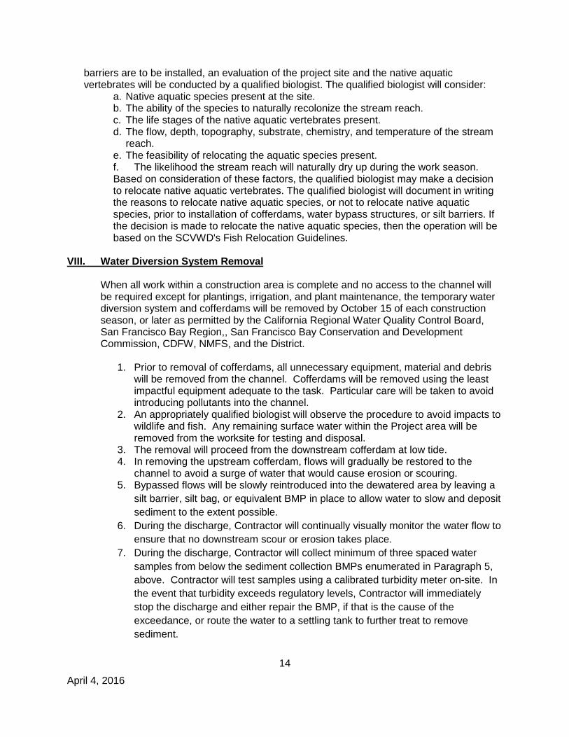
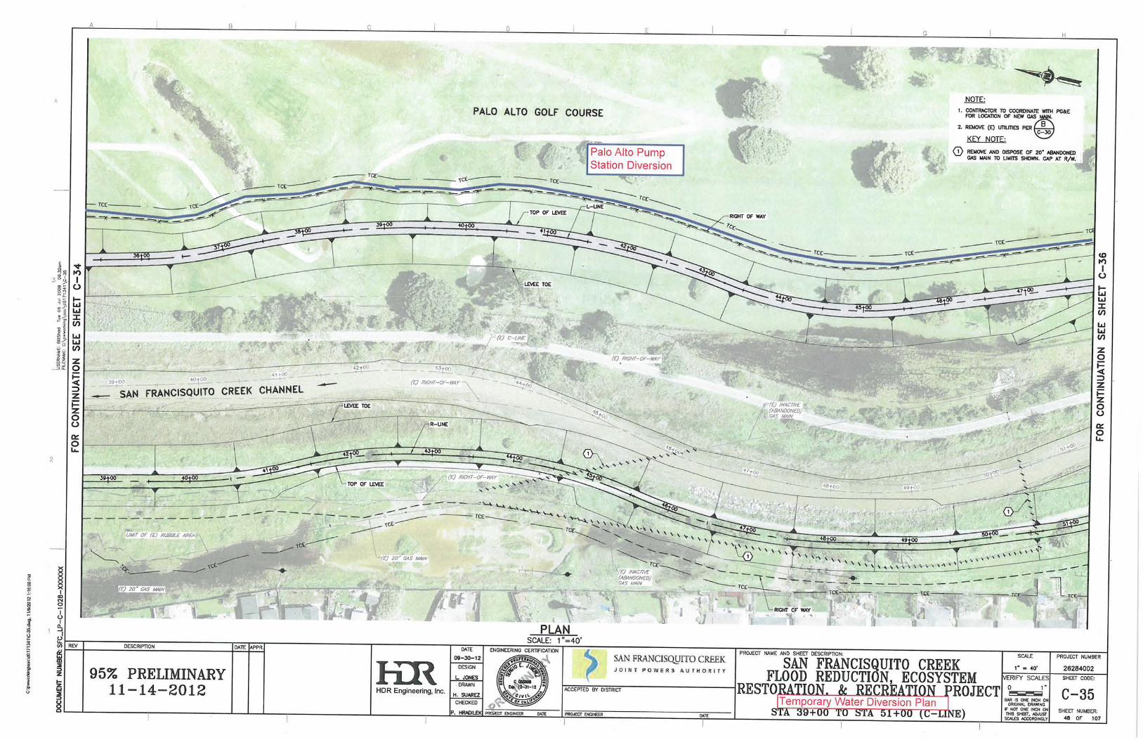
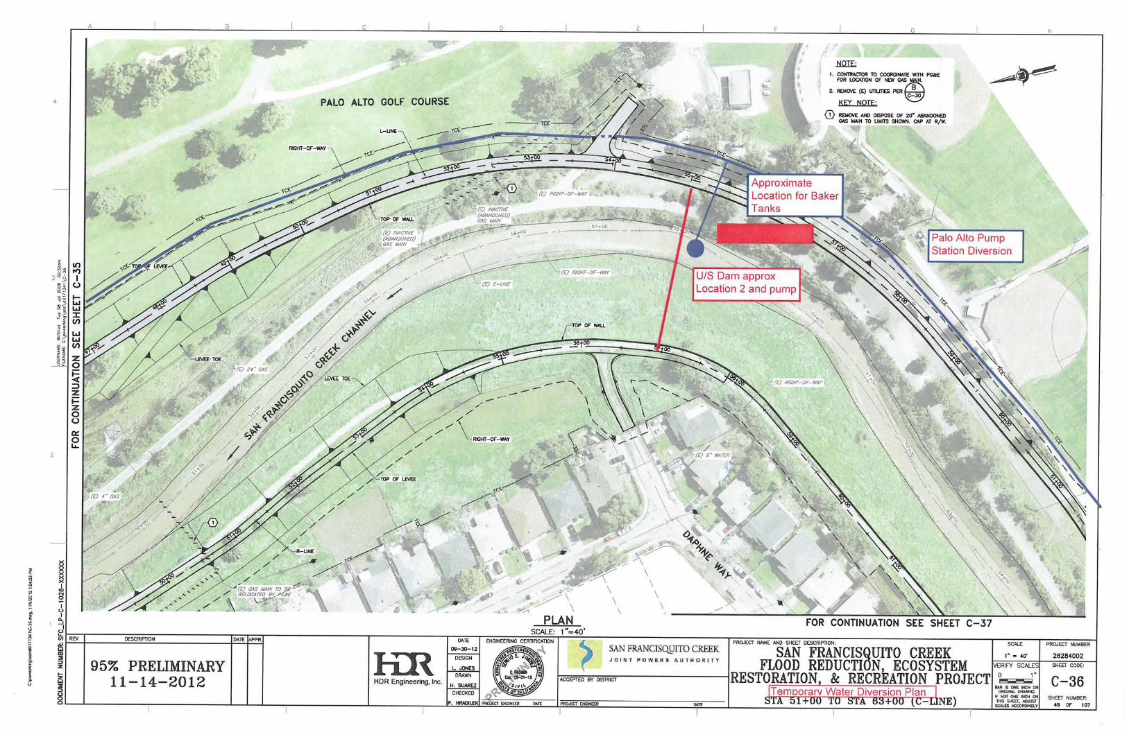
C. Water diversion will include cofferdams upstream (to intercept stream flows) and downstream (to block tidal Bay waters) of the work site. Stream flows upstream of the site will be pumped and piped through piping that bypasses the work site. Discharges from the two municipal pump stations will be pumped from the wet wells into the diversion piping. Please see Attachment A for connection locations of the municipal pump stations to diversion water line. In addition, the Contractor will identify means to dewater the work site and retain, test, and treat that water so as to meet all water quality effluent limitations as specified in the Regional Water Quality Control Board, San Francisco Bay Region, Basin Plan (Basin Plan).
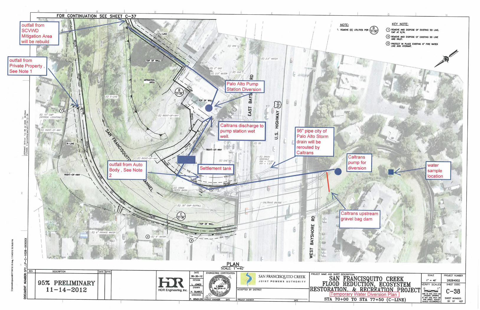
D. A Caltrans project is under construction to rebuild the bridges across San Francisquito Creek at East Bayshore Road, Highway 101, and West Bayshore Road. Caltrans is diverting flows and dewatering their project site under a separate permit from the Regional Board. The duration of their project is the same as for the District’s: through 2017. Therefore, Caltrans and the District have agreed to share diversion actions to the extent possible.
E. The Contractor is advised that depth to groundwater has been determined to be
in the range of 1 to 3 feet below existing channel invert. Dewatering sumps may be required during in-channel work.
F. The term “cofferdam” will be used to identify a structure preventing the intrusion
of water into the work area. Construction phasing will determine the specific locations of the cofferdams during what activity

2
April 4, 2016
G. Please note that what is presented below is the initial dewatering plan for the project. The design and implementation of the dewatering plan may be modified in the field as necessary upon agreement between the Contractor and the District.
H. State Specifications referenced are those of Standard Specifications, State of
California Department of Transportation 2010, revised, http://www.dot.ca.gov/hq/esc/oe/construction_contract_standards/std_specs/2010_StdSpecs/2010_StdSpecs.pdf.
I. Contractor will comply with best management practices in accordance with the
Stormwater Pollution Prevention Program, Article 18.01 of the Project construction contract Specifications. A Stormwater Pollution Prevention Plan (SWPPP) is part of the State Water Resources Control Board National Pollutant Discharge Elimination System (NPDES) General Permit for Discharges of Storm Water Runoff Associated with Construction and Land Disturbance Activity (Order No. DWQ-2009-0009, as amended by order Nos. 2010-0014-DWQ and 2012-006-DWQ) (Construction General Permit, CGP) and Maintenance Best Management Practices Gen-33 & Gen-34 (SCVWD 2014-2023 SMP) , see Attachment D. Contractor will implement all steps necessary in accordance with the Monitoring Plan, Attachment G.
J. State General Guidelines for Dewatering Plans
1. All work performed within waters of the State will be completed in a manner that meets the water quality objectives to ensure the protection of beneficial uses as specified in the Basin Plan.
2. All dewatering and diversion methods will be installed such that natural flow is
maintained upstream and downstream of the project area.
3. Any temporary dams or diversion will be installed such that the diversion does not cause sedimentation, siltation, or erosion upstream or downstream of the project area.
4. Screened pumps shall be used in accordance with CDFW’s fish screening criteria (http://www.dfq.ca.qov/fish/Resources/Proiects/Enqin/Enqin ScreenCriteria.asp) and in accordance with the NMFS Fish Screening Criteria for Anadromous Salmonids [available at: http://swr.nmfs.noaa.gov/hcd/fishscrn.pdf] and the Addendum for Juvenile Fish Screen Criteria for Pump Intakes [available at: http://swr.nmfs.noaa.gov/hcd/pumpcrit.pdf].NMFS Fish Screening Criteria.
K. Any changes to the approved plan that may have the potential to impact waters
of the State must be acceptable to the Regional Water Board's Executive Officer.
II. Cofferdams
3
April 4, 2016
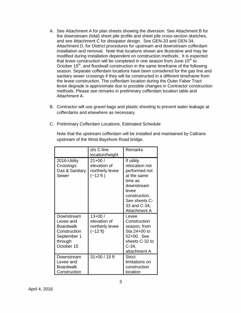
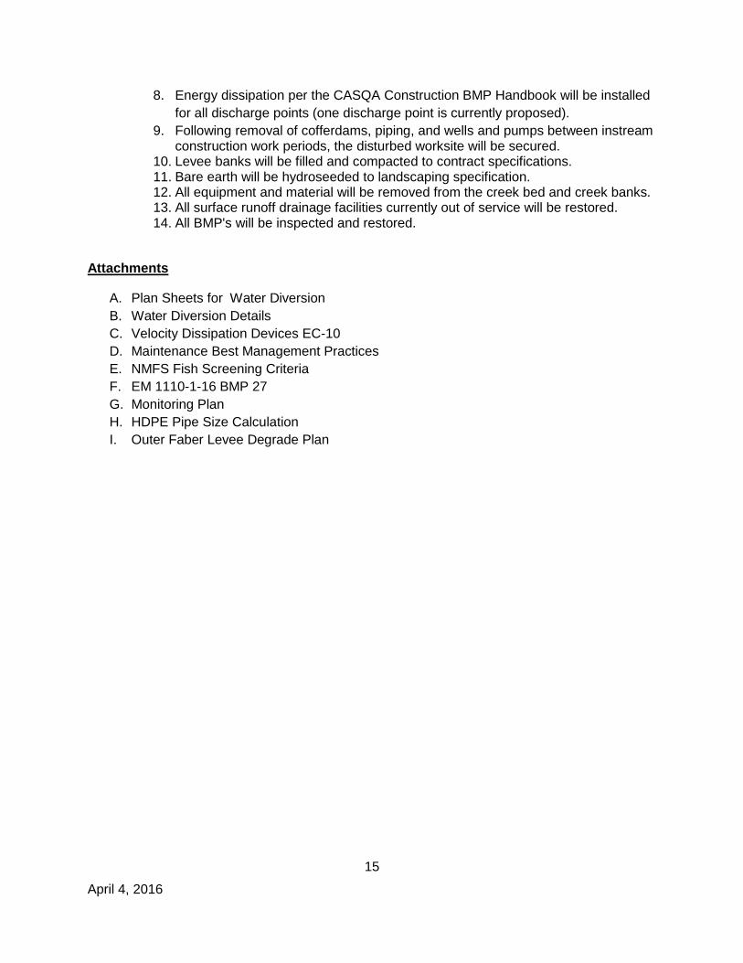
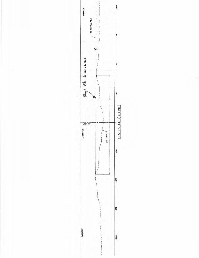
A. See Attachment A for plan sheets showing the diversion. See Attachment B for the downstream (tidal) sheet pile profile and sheet pile cross-section sketches, and see Attachment C for dissipator design. See GEN-33 and GEN-34, Attachment D, for District procedures for upstream and downstream cofferdam installation and removal. Note that locations shown are illustrative and may be modified during installation dependent on construction methods. It is expected that levee construction will be completed in one season from June 15th to October 15th, and floodwall construction in the same timeframe of the following season. Separate cofferdam locations have been considered for the gas line and sanitary sewer crossings if they will be constructed in a different timeframe from the levee construction. The cofferdam location during the Outer Faber Tract levee degrade is approximate due to possible changes in Contractor construction methods. Please see remarks in preliminary cofferdam location table and Attachment A.
B. Contractor will use gravel bags and plastic sheeting to prevent water leakage at
cofferdams and elsewhere as necessary.
C. Preliminary Cofferdam Locations, Estimated Schedule
Note that the upstream cofferdam will be installed and maintained by Caltrans
upstream of the West Bayshore Road bridge.
d/s C-line location/height
Remarks
2016-Utility Crossings: Gas & Sanitary Sewer
21+00 / elevation of northerly levee (~12 ft )
If utility relocation not performed not at the same time as downstream levee construction. See sheets C-33 and C-34, Attachment A
Downstream Levee and Boardwalk Construction September 1 through October 15
13+00 / elevation of northerly levee (~12 ft)
Levee Construction season, from Sta 24+00 to 52+00. See sheets C-32 to C-34, attachment A
Downstream Levee and Boardwalk Construction
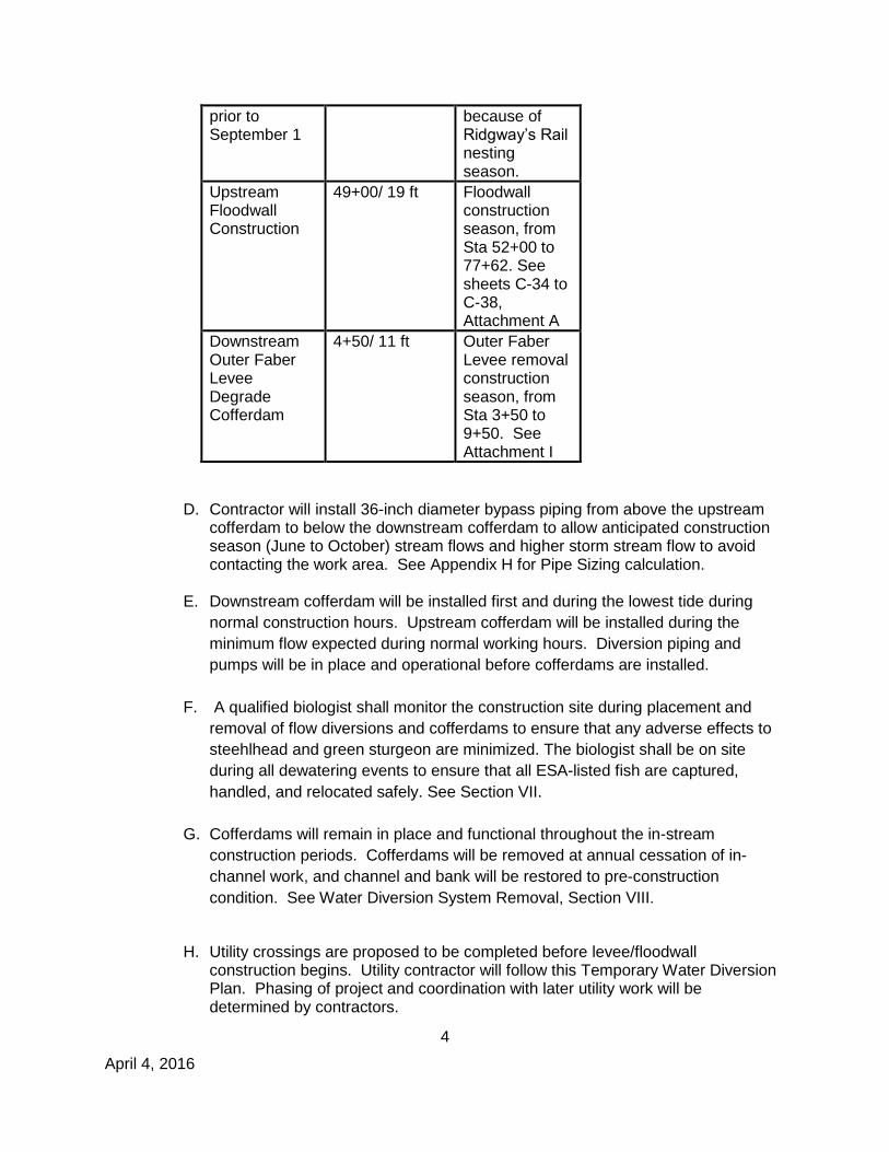
31+00 / 15 ft Strict limitations on construction location
4
April 4, 2016
prior to September 1
because of Ridgway’s Rail nesting season.
Upstream Floodwall Construction
49+00/ 19 ft Floodwall construction season, from Sta 52+00 to 77+62. See sheets C-34 to C-38, Attachment A
Downstream Outer Faber Levee Degrade Cofferdam
4+50/ 11 ft Outer Faber Levee removal construction season, from Sta 3+50 to 9+50. See Attachment I
D. Contractor will install 36-inch diameter bypass piping from above the upstream cofferdam to below the downstream cofferdam to allow anticipated construction season (June to October) stream flows and higher storm stream flow to avoid contacting the work area. See Appendix H for Pipe Sizing calculation.
E. Downstream cofferdam will be installed first and during the lowest tide during
normal construction hours. Upstream cofferdam will be installed during the
minimum flow expected during normal working hours. Diversion piping and
pumps will be in place and operational before cofferdams are installed.
F. A qualified biologist shall monitor the construction site during placement and
removal of flow diversions and cofferdams to ensure that any adverse effects to
steehlhead and green sturgeon are minimized. The biologist shall be on site
during all dewatering events to ensure that all ESA-listed fish are captured,
handled, and relocated safely. See Section VII.
G. Cofferdams will remain in place and functional throughout the in-stream
construction periods. Cofferdams will be removed at annual cessation of in-
channel work, and channel and bank will be restored to pre-construction
condition. See Water Diversion System Removal, Section VIII.
H. Utility crossings are proposed to be completed before levee/floodwall
construction begins. Utility contractor will follow this Temporary Water Diversion Plan. Phasing of project and coordination with later utility work will be determined by contractors.
5
April 4, 2016
I. Downstream Cofferdam
1. The downstream cofferdam will prevent Bay tidal waters from entering the
work site and will be installed below the most downstream construction element scheduled for installation during a specific construction season. The cofferdam will be as high as the highest immediately adjacent point on the right-hand bank (looking upstream), approximately 12 ft above the channel invert. The Mean Higher High Water tide is 7.1 ft NAVD 88; in no case will the downstream cofferdam height be below this elevation plus one foot of freeboard, 8.1 ft, NAVD 88.
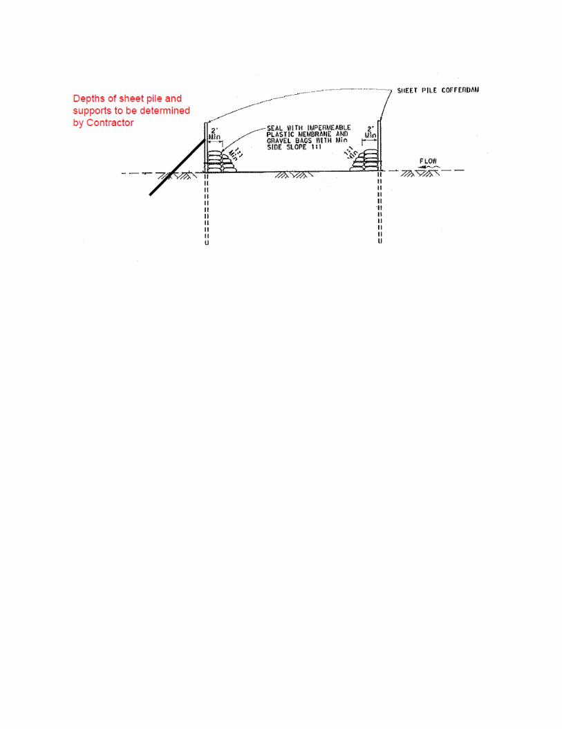
2. The downstream cofferdam will be braced from the appropriate height of the
sheet piles to instream embedment, 8 to 10 feet apart. Contractor will
determine over what width of the cofferdam the additional braces are
necessary.
J. Bay Levee Cofferdam and Silt Curtain
1. During excavation of the Bay Levee, a downstream cofferdam will be located
at approximately R-line station 3+00. The design will be the same as for the
downstream cofferdam described above. The height of the cofferdam will
equal the height of the adjacent Bay Levee.
2. On the outboard side of the Bay Levee, a Type 3 D.O.T. floating silt curtain or
approved equivalent will be installed to prevent sediment from entering the
adjacent marshland and San Francisco Bay. This type of floating silt curtain is
resistant to wind and high water velocity .See attachment F. USACE
engineering pamphlet 1110-1-16 BMP 27.
3. If Contractor can degrade the Outer Faber levee without entering the
channel, a floating silt curtain as described in 2, above, will be installed on the
channel side of the levee also. See Attachment I for Outer Faber levee
degrading plan and sections.
K. Contractor will maintain dewatering discharge in accordance with SWPPP and
CGP requirements.
L. The Upstream Cofferdam
1. The upstream cofferdam will prevent stream flows from entering the work
site. As described in Paragraph I.C., above, Caltrans will install and maintain the upstream cofferdam in accordance with their permit during in-channel
6
April 4, 2016
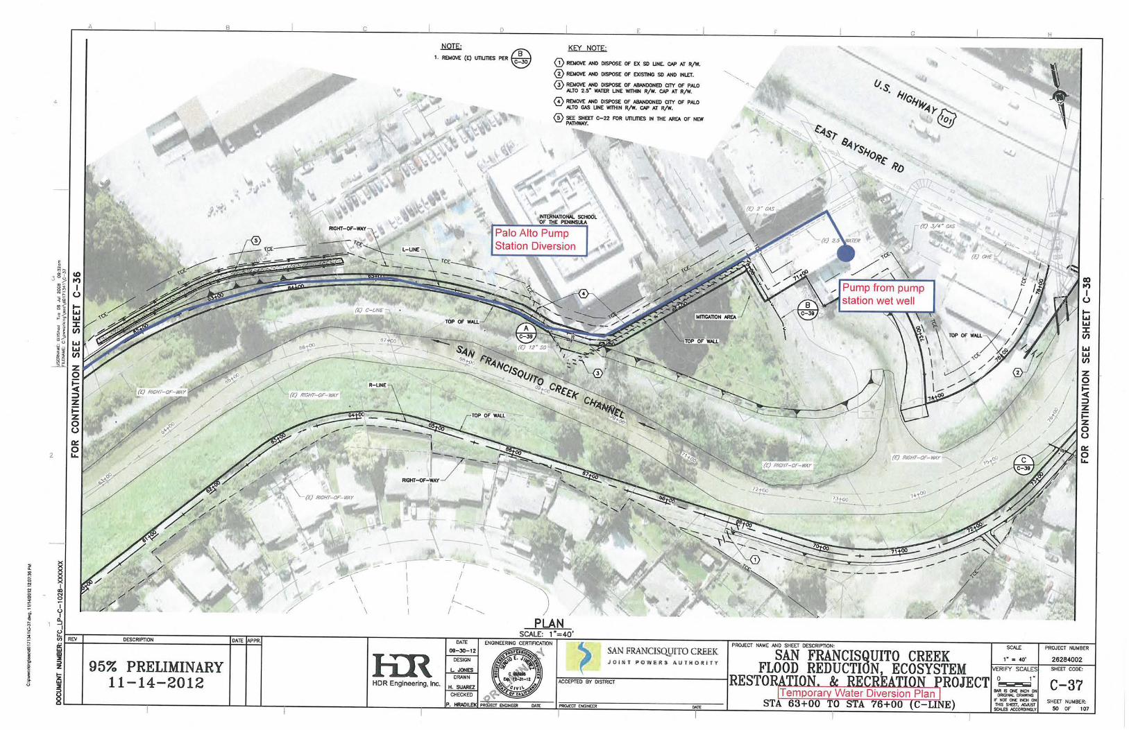
work for the duration of both projects. Upstream flows will be collected at a gravel dam and pumped through sediment removal treatment mechanism into the wet well at the Palo Alto Pump Station. During the period of upstream water diversion, the pump station operation will be shut down. From there it is the Contractor’s responsibility to convey that water from the Palo Alto Pump Station wet well along the L-line levee and discharge into San Francisquito Bay using appropriate turbidity-reduction methods.
2. Construction season (June to October) water flows are anticipated based on
the maximum 73-year mean daily flow at the USGS gage on SF Creek at the Stanford golf course between June 1 and October 15. This flow is 0.5 cubic feet per second (cfs) with a gage height of 0.3 ft. For a value at the project site, an additional 1 cfs is added for summer urban runoff, bringing the total anticipated flow to 1.5 cfs, with a gage height of 0.4 ft.
3. The Contractor is advised that Construction season stream flows can vary
significantly depending on off-season storm events, and high flows can last several hours. Recent historical summer storms have produced flows of 3.2 cfs (2012), 32 cfs (2011), and 4.1 cfs (2010). The temporary water diversion structure will be able to pass the 2011 32-cfs flow as pumped from the area of water detention above the dam.
M. If there is a forecast storm event as determined in accordance with the
requirements of the NPDES Construction permit for the project (see Article
18.01), Contractor will prepare and implement the Rain Event Action Plan
(REAP). If Contractor observes the reservoir upstream of the cofferdam is
nearly overtopping elevation, Contractor will increase pumping to the extent
possible to avoid overtopping. However, if stream flow from a significant storm
event overtops the upstream cofferdam, Contractor will pump this overflow into
Baker tanks to be tested before discharge as described below.
N. The contractor will ensure that a QSP develops a REAP 48 hours prior to any
likely precipitation event and that a QSP develop the REAPs for all phases of
construction. The Contractor will ensure that the REAP includes, at a minimum,
Site Address, Calculated Risk Level, Site Storm Water Manager Information
including the name, company, and 24-hour emergency telephone number,
Erosion and Sediment Control provider information including the name,
company, and 24-hour emergency telephone number, Storm Water Sampling
Agent information including the name, company, and 24-hour emergency
telephone number. The Contractor will ensure that the REAP includes, at a
minimum, activities associated with each construction phase, trades that are
active on the construction site during each construction phase, trade contractor
information and suggested actions for each project phase.
O. Dewatering Project Site
1. The project area will be dewatered of surface water by means of pumping
the water from the stream or ponded locations into Baker tanks with a total
capacity of 21,000 gallons for testing and appropriate discharge or disposal.
7
April 4, 2016
Contactor is advised to use Palo Alto Golf Course and Baylands Athletic
Center as staging areas for tanks. The number and scheduling of tanks
would be determined by Contractor based on site condition and amount of
water to be removed. See Attachment A for proposed tank locations.
2. Contractor will make available an appropriate number and size of water
storage tanks (Baker tanks) and pumps in preparation for collecting any
water from the work site. Water from the work site will be collected in the
Baker tanks and tested prior to discharge downstream if water meets the
requirements of the General Construction Permit and effluent limitations
in the 401 Certification. Water detained behind the upstream cofferdam
will be pumped and piped past the work area and be discharged below
the downstream cofferdam based on the Monitoring Plan, see
Attachment G.
3. Groundwater recovered from wells will be tested in accordance with
Section VI on the first day of pumping. If no pollutants are found,
groundwater will be assumed to be clean and diverted directly into
bypass piping.
III. Materials
A. Cofferdams
1. Cofferdams will be constructed of steel sheet pile embedded no less than 15 feet below the channel invert. Steel sheet piles for cofferdam must comply with Section 49-2.05B of the State Specifications. Sheet piles will not exhibit corrosion beyond surface rust which does not pose a risk to structural strength.
2. Piles in easier driving conditions, as expected for this project in softer bay material, based on Caltrans’ experience on the Highway 101 Bridge Replacement Project and into materials shown to be easier in geotechnical boring logs, may be installed with a backhoe or hammer attached to a backhoe.
3. Cofferdams will be visually inspected for stability, integrity, and leakage daily. Any abnormality will be corrected immediately. Temporary leakage control measures include plastic sheeting and gravel bags placed on the wet side of the sheet piles. Measures to control stability problems include additional bracing. Lack of structural integrity may require patching or replacement and/or removal of sheet pile. Cofferdams will not exhibit structural corrosion for the duration of their installations.
B. Gravel Bags
1. Gravel material will be between 0.4 and 0.8 inch in diameter, and will be clean and free from clay balls, organic matter, and other deleterious
8
April 4, 2016
materials. The gravel bags will be placed on top of the plastic sheeting, which will be laid upon the channel invert or bank to prevent leakage. The gravel bags will be arranged so that each layer of gravel bag placed will be staggered in pyramid-like fashion. After the final height has been reached, the original plastic sheeting will be placed on top of the sandbags. To hold the plastic sheeting in place, gravel bags will be placed above the top plastic sheeting. Gravel bags on top of the plastic sheeting will be spaced no more than 3 feet apart.
2. Gravel must:
a. Be clean, hard, sound, durable , uniform in quality , and free of
any detrimental quantity of soft, thin, elongated or laminated pieces, disintegrated material, organic matter, or other deleterious substances
b. Be composed entirely of particles that have no more than one
fractured face, and be from ⅜ to ¾ inch in diameter. Have a cleanness value of at least 85, as determined by the California Department of Transportation Test 227, Method of Test for Evaluating Cleanness of Coarse Aggregate
3. Gravel-filled bags must comply to Caltrans Standard Specification 2010
Section 13-5.02G as below:
a. Be made of geosynthetic material. b. Have inside dimensions from 24 to 32 inches long and from 16 to
20 inches wide. c. Have a bound opening to retain gravel. The opening must be
sewn with yarn, bound with wire, or secured with a closure device.
d. Weigh from 30 to 50 pounds when filled with gravel.
4. Plastic sheeting must be:
a. Single ply, commercial quality, non-photodegradable polyethylene with a minimum thickness of 10 mils under ASTM D 5199.
b. Free of holes, punctures, tears or other defects that compromise the impermeability of the material.
c. Suitable for use as an impermeable membrane. C. Pipe
1. Pipe will be of 36-inch nominal diameter minimum HDPE to be fused
together. Piping will be installed as shown on attached figures or alternate
location as approved by District to allow upstream flows to pass the work site.
Installation will ensure that stream flows will not be released into the work
site.
2. Pipe will:
9
April 4, 2016
a. Be clean, uncoated, in good condition, paint oil dirt or other
residues that could potentially contribute to water pollution;
b. Be adequately supported for planned loads as identified by the Contractor;
c. Use watertight joints;
d. Be made of HDPE material suitable for clean water and be free
of any extraneous material, including banned, hazardous, or
unlawful substances;
e. Be smooth walled.
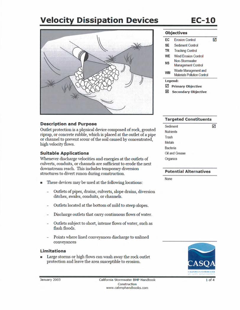
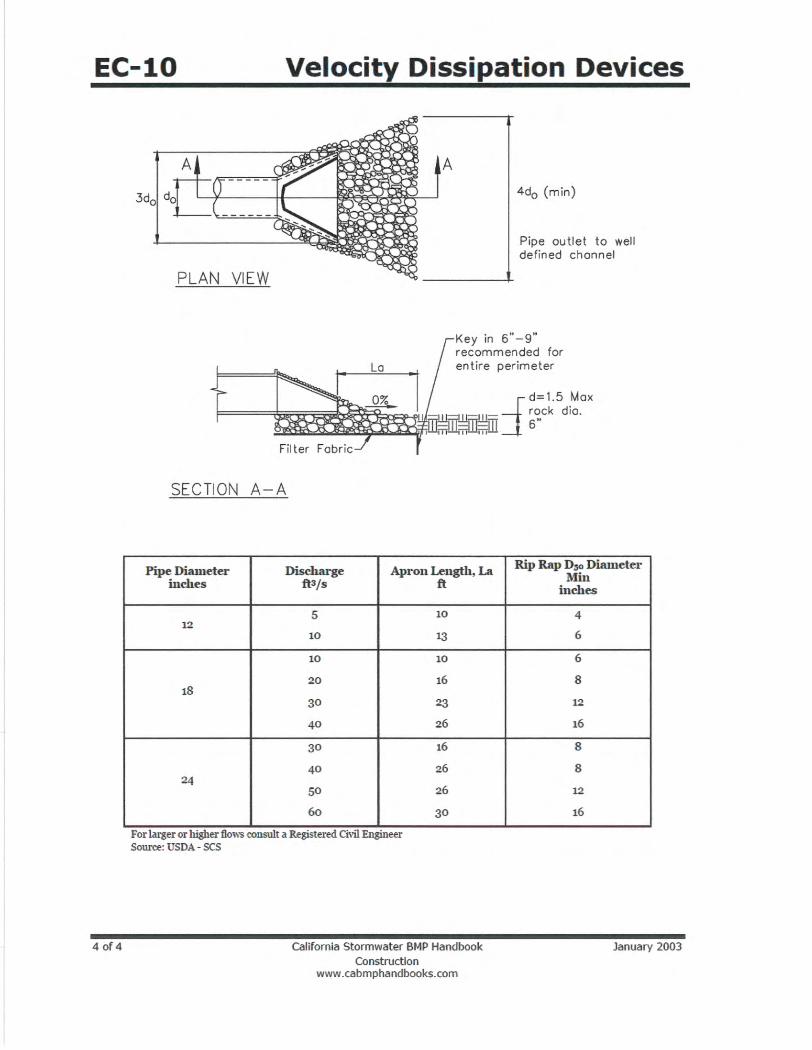
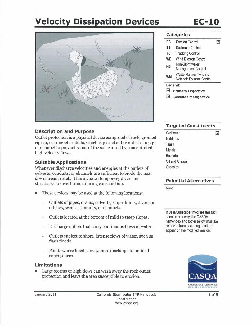
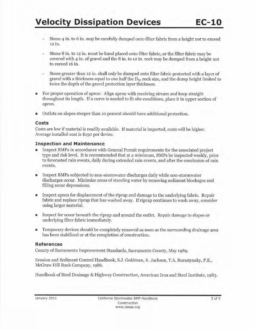
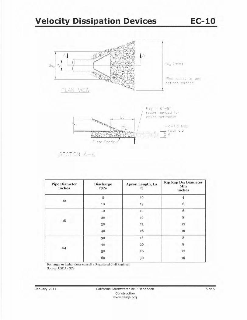
3. The pipe outlet will be rocked with rock riprap in such fashion as to prevent
erosion at the outlet in accordance with CASQA Construction BMP EC-10 (Attachment C).
D. Pumps
1. Pumps will be on site to dewater the work site as necessary. Pumps will be
sized by the Contractor. Discharge from the dewatered area will be contained and tested in accordance with the requirements of the NPDES General Construction Permit. Pumps will be required (1) to reroute water from the stream, which accumulates above the upstream cofferdam; (2) to dewater the construction area above the downstream cofferdam or where ponded; and (3) at each of the two municipal pump stations (see below).
2. Instream pump(s) will have appropriate fish exclusion devices to prevent fish from being taken up by the pump(s). Contractor’s plan will be in accordance with criteria in Attachment E.
3. If groundwater seepage is encountered, pumps will be used to discharge the
incidental flows to various intakes of the 36-inch pipe structure. It is anticipated that for in-channel construction from station 41+00 to 54+00, groundwater will be encountered and pumping will be used to discharge the water to Baker tanks to settle and be tested. See Attachment A, Sheets C-35 and C-36. For other areas in which groundwater dewatering is necessary in an excavation area, the water will be routed to the Baker tanks to settle and be tested. Pumps in wells outside excavation areas to lower the water table (interception pumps) will pump into diversion piping. The interception pump locations are shown in Attachment A, but these pumps will be used only as determined to be necessary for site conditions by the District construction manager and Contractor. When discharging into the intakes of the 36-inch pipe, the top opening of the intake will also be sealed to maintain air pressure within the pipe.
a. O’Connor Street Pump Station
b. The City of East Palo Alto operates a storm water pump station past
the southerly end of O’Connor Street. Construction work within the City will discharge dewatering flows expected to be up to 350 gallons
10
April 4, 2016
per minute or 0.78 cfs through municipal storm drains to the pump station. Additional water from urban sources will also be routed to this pump station, which normally outflows to the work area. To prevent flows from the pump station entering the work area, Contractor will pump water which accumulates in the pump station wet well directly to the channel downstream of the downstream cofferdam or join the pump station outflow pipe to the stream diversion pipe. In either case, discharge to the channel will be through the flow dissipator. Pump and pipe will be determined by Contractor based on information provided by the City of East Palo Alto.
c. Palo Alto Pump Station
d. The City of Palo Alto operates a storm water pump station which will
normally outflow within the work area. Contractor will pump water which accumulates in the pump station wet well directly to the channel downstream of the downstream cofferdam through the flow dissipator.
E. Energy dissipation
1. Contractor will install and maintain energy dissipation BMPs in accordance
with Attachment C at all water discharge points (one discharge point is
currently proposed, see Attachment A).
IV. Additional Storm Drain Outfalls in the Work Area
A. Storm drain outfall on the south bank at approximate C-line station 76+00. The entire line including the inlet and outfall will be removed as part of construction.
B. 96-inch diameter City of Palo Alto storm drain outfall on the south bank at approximate
C-line station 77+40 for overflows that cannot be handled by the City’s San Francisquito Creek Pump Station. This line will be reduced and rerouted into the new East Bayshore Road bridge abutment by Caltrans.
C. Outfall channel from the San Francisquito Creek Pump Station on the south bank at
approximate C-line station 74+00. Minimal flows are expected during construction season unless a storm occurs. Contractor will ensure a QSP develop a Rain Event Action Plan 48 hours prior to any likely precipitation event. See Section II.M.
D. Storm drain outfall on the north bank at approximate C-line station 73+50. Minimal
flows are expected during construction season unless a storm occurs. Contractor will ensure a QSP develop a Rain Event Action Plan 48 hours prior to any likely precipitation event. See Section II.M.
11
April 4, 2016
E. Contractor is responsible for identifying and managing flows from other outfalls into the work area. It is expected that outfall flows will be minor during the construction season. Contractor may collect the outfall flows with other waters within the work site, such as groundwater, in which case the extracted water will be tested after routing to Baker tanks, see Section VI.A.
V. Dissipators
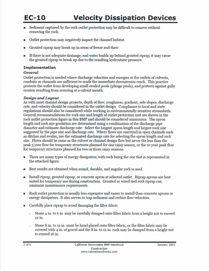
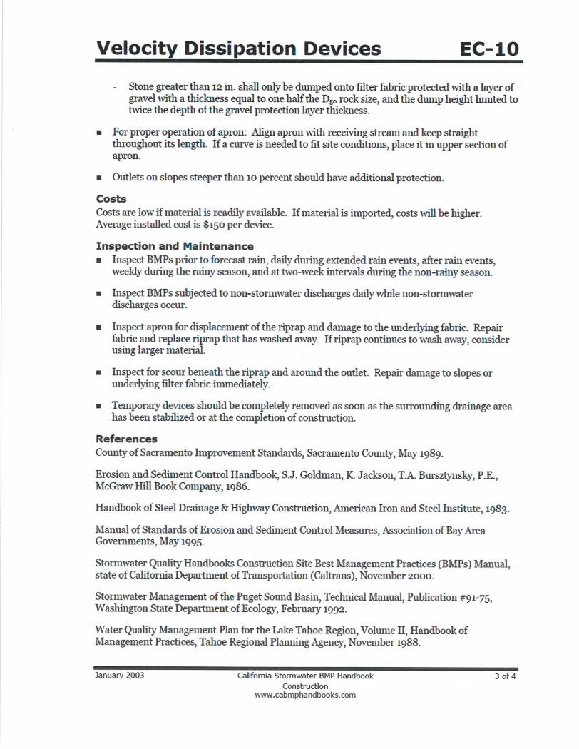
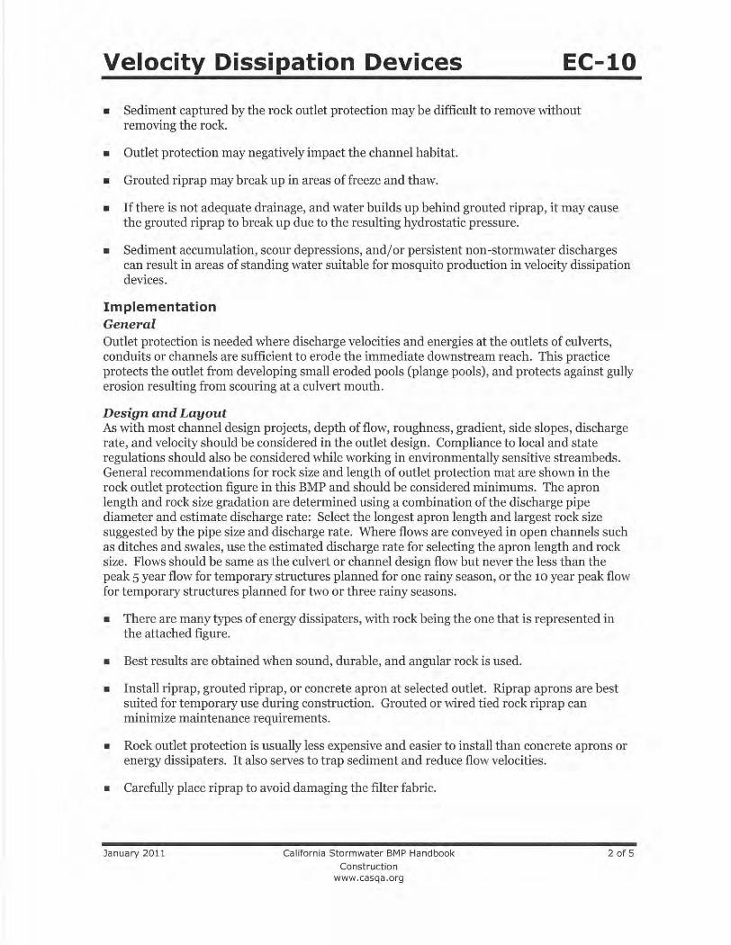
Diversion pipe flow velocity dissipators will be installed downstream of the cofferdam on existing banks. Contractor will note that pipe discharges will occur from low to high tide, and outlets will be located above Mean Higher High Water. Dissipators may be under tide water and will be designed to resist degradation by tidal movement. Dissipators will be installed from pipe outlet to channel invert. Design will be in accordance with CASQA Construction BMP EC-10, see Attachment C). In accordance with EC-10, inspect dissipator apron for displacement of the riprap and damage to the underlying fabric. Repair fabric and riprap that has washed away. Consider using larger riprap. Inspect for scour beneath the riprap and around the outlet. Repair damage to slopes or underlying fabric immediately.
VI. Inspection, Sampling, and Testing
A. All activities associated with water diversion will be governed in accordance with the State Water Resources Control Board Construction General Permit 2009-0009-DWQ amended by 2010-0014-DWQ & 2012-0006-DWQ (CGP), Risk Level 2, and as described in the project’s Storm water Pollution Prevention Plan (SWPPP). The Contractor will be responsible for the SWPPP, prepared by a Qualified SWPPP Developer and implemented by a Qualified SWPPP Practitioner.
B. Contractor sampling activities at the project location will be performed or supervised by a
QSP representing the Contractor. Contractor will perform weekly inspections and observations, and at least once each 24-hour period during extended storm events, to identify and record BMPs that need maintenance to operate effectively, that have failed, or that could fail to operate as intended. Upon identifying failures or other shortcomings, as directed by the QSP, Contractor will begin implementing repairs or design changes to BMPs within 72 hours of identification and complete the changes as soon as possible. For each inspection required, Contractor will complete an inspection checklist, using a form will ensure that all inspection, maintenance provided by the State Water Board or Regional Water Board or in an alternative format. Contractor will ensure that checklists will remain onsite with the SWPPP and at a minimum, will include:
1. Inspection date and date the inspection report was written, 2. Weather information, including presence or absence of precipitation, estimate of
beginning of qualifying storm event duration of event, time elapsed since last storm, and approximate amount of rainfall in inches,
3. Site information, including stage of construction, activities completed, and approximate area of the site exposed.
4. A description of any BMPs evaluated and any deficiencies noted. 5. If the construction site is safely accessible during inclement weather, list the
observations of all BMPs: erosion controls, sediment controls, chemical and
12
April 4, 2016
waste controls, and non-storm water controls. Otherwise, list the results of visual inspections at all relevant outfalls, discharge points, downstream locations and any projected maintenance activities.
6. Report the presence of noticeable odors or of any visible sheen onthe surface of any discharges.
7. Any corrective actions required, including any necessary changes to the SWPPP and the associated implementation dates
8. Photographs taken during the inspection, if any. 9. Inspector’s name, title, and signature.
C. Samples will be collected and analyzed as required by the CGP for Risk 2 projects,
Appendix D, Table 3:
1. pH: Field test with calibrated portable instrument, detection limit 0.2 pH units, Numerical Action Limits (NAL): lower NAL pH=6.5 and upper NAL pH=8.5.
2. Turbidity: Field test with calibrated portable instrument and/or EPA 0180.1, detection limit 1 Nephelometric Turbidity Unit (NTU), NAL=250 NTU.
3. Dissolved sulfide: Field test with calibrated portable instrument, not greater than 0.1 mg/L.
4. Dissolved oxygen: Field test with calibrated portable instrument, 5.0 mg/l hourly average for discharge into tidal waters; 7.0 mg/l hourly average for discharge into non-tidal waters.
D. Water collected from the construction site (run-on, ponded water, collected groundwater)
will be visually inspected and sampled per Risk Level 2 requirements. E. Diverted water will flow by gravity or by pumping from above the upstream dam to below
the downstream dam, without being in contact with the construction site. F. Water from within the project site—run-on, collected groundwater, ponded water—
exceeding NALs or potentially containing contaminants will be pumped or otherwise routed to storage tanks for testing, treating and eventual discharge or disposal. Sediments will be removed by settling; pH will be adjusted by appropriate methods. Only compliant water will be discharged. Otherwise, contaminated water will be disposed of in accordance with all applicable regulations.
G. There is no evidence that any sediment in collected surface or groundwater can not be practicably treated with passive settled methodology. Should such methodology prove ineffective, Contractor will design and operate an Active Treatment System as defined by the CGP to reduce turbidity below regulatory requirements.
H. It will be the Contractor’s responsibility to select locations for water collection on-site and
subsequent storage for testing, treating, and disposal. Compliant water could either be routed into the existing diversion piping, or into separate piping, discharging into the flow dissipation BMP.
I. Contractor will follow direction of Monitoring Plan, Attachment G.
13
April 4, 2016
VII. Fish Relocation
A. As required by California Department of Fish and Wildlife (CDFW) or National Marine Fisheries Service (NMFS), during dewatering operations, all reasonable efforts shall be made to capture and move all stranded fish observed in the dewatering area. Methods used to capture and relocate fish may include dip net and seine. Captured fish will be released in a suitable wetted area up or downstream of the dewatered area.
B. For any species listed under the California Endangered Species Act or Federal
Endangered Species Act, only a qualified biologist with the necessary permits issued by CDFW and/or NMFS can supervise the relocation of listed species. Handling of said listed species shall be restricted solely to a qualified biologist with the necessary permits issued by CDFW and/or NMFS. ESA-listed fish shall only be handled with extreme care and kept in water to the maximum extent possible during relocation activities. All captured fish shall be kept in cool, shaded, aerated water protected from excessive noise, jostling, or overcrowding any time they are not in the stream and fish shall not be removed from this water except when released. To avoid predation, the biologist shall have at least two containers and segregate young-of-year fish from larger age-classes and other potential aquatic predators. Captured steelhead and green sturgeon must be relocated, as soon as possible, to a suitable in-stream or estuary location in which suitable habitat conditions are present and similar to capture sites to allow for adequate survival of transported fish and fish already present.
C. The permittee shall contact CDFW no less than 24 hours and no greater than 72 hours
of relocation activates. In the event the Permittee intends to dispatch non-native fish species, Permitee shall coordinate with CDFW fisheries staff to apply for any applicable permits such as a permit to destroy nuisance fish.
D. The Permitee shall contact NMFS (biologist Amanda Morrison) one week prior to capture activities in order to provide an opportunity for NMFS staff to observe the activities.
E. The qualified biologist will collect the following data during fish relocation activates: description of the location from which fish were removed and the release site including photographs; the date and time of the relocation effort; a description of water quality at release sites at the time of release, including, at a minimum, water temperature and dissolved oxygen levels; a description of the equipment and methods used to collect, hold, and transport ESA-listed fish; the number of fish relocated by species; the number of fish injured or killed by species and a brief narrative of the circumstances surrounding ESA-listed fish injuries or mortalities; and a description of any problems which may have arisen during the relocation activities and a statement as to whether or not the activities had any unforeseen effects.
F. Aquatic Vertebrates: Effects on native aquatic vertebrates will be avoided or minimized. If native aquatic vertebrates are present when cofferdams, water bypass structures, and silt
14
April 4, 2016
barriers are to be installed, an evaluation of the project site and the native aquatic vertebrates will be conducted by a qualified biologist. The qualified biologist will consider:
a. Native aquatic species present at the site. b. The ability of the species to naturally recolonize the stream reach. c. The life stages of the native aquatic vertebrates present. d. The flow, depth, topography, substrate, chemistry, and temperature of the stream
reach. e. The feasibility of relocating the aquatic species present. f. The likelihood the stream reach will naturally dry up during the work season. Based on consideration of these factors, the qualified biologist may make a decision to relocate native aquatic vertebrates. The qualified biologist will document in writing the reasons to relocate native aquatic species, or not to relocate native aquatic species, prior to installation of cofferdams, water bypass structures, or silt barriers. If the decision is made to relocate the native aquatic species, then the operation will be based on the SCVWD's Fish Relocation Guidelines.
VIII. Water Diversion System Removal
When all work within a construction area is complete and no access to the channel will be required except for plantings, irrigation, and plant maintenance, the temporary water diversion system and cofferdams will be removed by October 15 of each construction season, or later as permitted by the California Regional Water Quality Control Board, San Francisco Bay Region,, San Francisco Bay Conservation and Development Commission, CDFW, NMFS, and the District.
1. Prior to removal of cofferdams, all unnecessary equipment, material and debris
will be removed from the channel. Cofferdams will be removed using the least impactful equipment adequate to the task. Particular care will be taken to avoid introducing pollutants into the channel.
2. An appropriately qualified biologist will observe the procedure to avoid impacts to wildlife and fish. Any remaining surface water within the Project area will be removed from the worksite for testing and disposal.
3. The removal will proceed from the downstream cofferdam at low tide. 4. In removing the upstream cofferdam, flows will gradually be restored to the
channel to avoid a surge of water that would cause erosion or scouring. 5. Bypassed flows will be slowly reintroduced into the dewatered area by leaving a
silt barrier, silt bag, or equivalent BMP in place to allow water to slow and deposit
sediment to the extent possible.
6. During the discharge, Contractor will continually visually monitor the water flow to
ensure that no downstream scour or erosion takes place.
7. During the discharge, Contractor will collect minimum of three spaced water
samples from below the sediment collection BMPs enumerated in Paragraph 5,
above. Contractor will test samples using a calibrated turbidity meter on-site. In
the event that turbidity exceeds regulatory levels, Contractor will immediately
stop the discharge and either repair the BMP, if that is the cause of the
exceedance, or route the water to a settling tank to further treat to remove
sediment.
15
April 4, 2016
8. Energy dissipation per the CASQA Construction BMP Handbook will be installed
for all discharge points (one discharge point is currently proposed).
9. Following removal of cofferdams, piping, and wells and pumps between instream construction work periods, the disturbed worksite will be secured.
10. Levee banks will be filled and compacted to contract specifications. 11. Bare earth will be hydroseeded to landscaping specification. 12. All equipment and material will be removed from the creek bed and creek banks. 13. All surface runoff drainage facilities currently out of service will be restored. 14. All BMP's will be inspected and restored.
Attachments
A. Plan Sheets for Water Diversion
B. Water Diversion Details
C. Velocity Dissipation Devices EC-10
D. Maintenance Best Management Practices
E. NMFS Fish Screening Criteria
F. EM 1110-1-16 BMP 27
G. Monitoring Plan
H. HDPE Pipe Size Calculation
I. Outer Faber Levee Degrade Plan

Attachment F – Best Management Practices
Santa Clara Valley Water District 18 Stream Maintenance Program Update 2014–2023
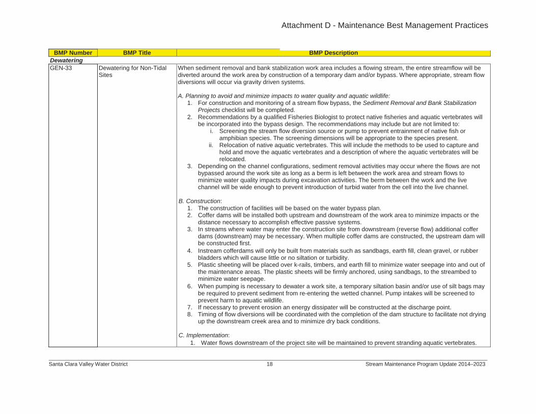
BMP Number BMP Title BMP DescriptionDewateringGEN-33 Dewatering for Non-Tidal
SitesWhen sediment removal and bank stabilization work area includes a flowing stream, the entire streamflow will be diverted around the work area by construction of a temporary dam and/or bypass. Where appropriate, stream flow diversions will occur via gravity driven systems.
A. Planning to avoid and minimize impacts to water quality and aquatic wildlife:1. For construction and monitoring of a stream flow bypass, the Sediment Removal and Bank Stabilization
Projects checklist will be completed.2. Recommendations by a qualified Fisheries Biologist to protect native fisheries and aquatic vertebrates will
be incorporated into the bypass design. The recommendations may include but are not limited to:i. Screening the stream flow diversion source or pump to prevent entrainment of native fish or
amphibian species. The screening dimensions will be appropriate to the species present. ii. Relocation of native aquatic vertebrates. This will include the methods to be used to capture and
hold and move the aquatic vertebrates and a description of where the aquatic vertebrates will be relocated.
3. Depending on the channel configurations, sediment removal activities may occur where the flows are not bypassed around the work site as long as a berm is left between the work area and stream flows to minimize water quality impacts during excavation activities. The berm between the work and the live channel will be wide enough to prevent introduction of turbid water from the cell into the live channel.
B. Construction:1. The construction of facilities will be based on the water bypass plan. 2. Coffer dams will be installed both upstream and downstream of the work area to minimize impacts or the
distance necessary to accomplish effective passive systems.3. In streams where water may enter the construction site from downstream (reverse flow) additional coffer
dams (downstream) may be necessary. When multiple coffer dams are constructed, the upstream dam will be constructed first.
4. Instream cofferdams will only be built from materials such as sandbags, earth fill, clean gravel, or rubber bladders which will cause little or no siltation or turbidity.
5. Plastic sheeting will be placed over k-rails, timbers, and earth fill to minimize water seepage into and out of the maintenance areas. The plastic sheets will be firmly anchored, using sandbags, to the streambed to minimize water seepage.
6. When pumping is necessary to dewater a work site, a temporary siltation basin and/or use of silt bags may be required to prevent sediment from re-entering the wetted channel. Pump intakes will be screened to prevent harm to aquatic wildlife.
7. If necessary to prevent erosion an energy dissipater will be constructed at the discharge point. 8. Timing of flow diversions will be coordinated with the completion of the dam structure to facilitate not drying
up the downstream creek area and to minimize dry back conditions.
C. Implementation:1. Water flows downstream of the project site will be maintained to prevent stranding aquatic vertebrates.
Attachment D - Maintenance Best Management Practices
Attachment F – Best Management Practices
Santa Clara Valley Water District 19 Stream Maintenance Program Update 2014–2023
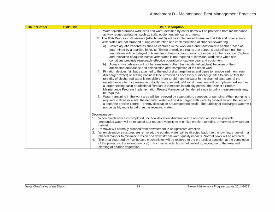
BMP Number BMP Title BMP Description2. Water diverted around work sites and water detained by coffer dams will be protected from maintenance
activity-related pollutants, such as soils, equipment lubricants or fuels.3. The Fish Relocation Guidelines (Attachment B) will be implemented to ensure that fish and other aquatic
vertebrates are not stranded during construction and implementation of channel dewatering. a) Native aquatic vertebrates shall be captured in the work area and transferred to another reach as
determined by a qualified biologist. Timing of work in streams that supports a significant number of amphibians will be delayed until metamorphosis occurs to minimize impacts to the resource. Capture and relocation of aquatic native vertebrates is not required at individual work sites when site conditions preclude reasonably effective operation of capture gear and equipment.
b) Aquatic invertebrates will not be transferred (other than incidental catches) because of their anticipated abundance and colonization after completion of the repair work.
4. Filtration devices (silt bags attached to the end of discharge hoses and pipes to remove sediment from discharged water) or settling basins will be provided as necessary at discharge sites to ensure that the turbidity of discharged water is not visibly more turbid than the water in the channel upstream of the maintenance site. If increases in turbidity are observed, additional measures will be implemented such as a larger settling basin or additional filtration. If increases in turbidity persist, the District’s Stream Maintenance Program Implementation Project Manager will be alerted since turbidity measurements may be required.
5. Water remaining in the work area will be removed by evaporation, seepage, or pumping. When pumping is required to dewater a site, the decanted water will be discharged with water bypassed around the site or in a separate erosion control – energy dissipation area/vegetated swale. The turbidity of discharged water will not be visibly more turbid than the receiving water.
Deconstruction:1. When maintenance is completed, the flow diversion structure will be removed as soon as possible.
Impounded water will be released at a reduced velocity to minimize erosion, turbidity, or harm to downstream habitat.
2. Removal will normally proceed from downstream in an upstream direction.3. When diversion structures are removed, the ponded water will be directed back into the low-flow channel in a
phased manner to minimize erosion and downstream water quality impacts. Normal flows will be restored.4. The area disturbed by flow bypass mechanisms will be restored to the pre-project condition at the completion
of the project (to the extent practical). This may include, but is not limited to, recontouring the area and planting of riparian vegetation.
Attachment D - Maintenance Best Management Practices
Attachment F – Best Management Practices
Santa Clara Valley Water District 20 Stream Maintenance Program Update 2014–2023
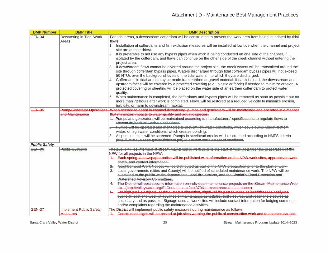
BMP Number BMP Title BMP DescriptionGEN-34 Dewatering in Tidal Work
AreasFor tidal areas, a downstream cofferdam will be constructed to prevent the work area from being inundated by tidal flows.1. Installation of cofferdams and fish exclusion measures will be installed at low tide when the channel and project
site are at their driest.2. It is preferable to not use any bypass pipes when work is being conducted on one side of the channel, ifs
3. If downstream flows cannot be diverted around the project site, the creek waters will be transmitted around the site through cofferdam bypass pipes. Waters discharged through tidal cofferdam bypass pipes will not exceed50 NTUs over the background levels of the tidal waters into which they are discharged.
isolated by the cofferdam, and flows can continue on the other side of the creek channel without entering the project area.
4. Cofferdams in tidal areas may be made from earthen or gravel material. If earth is used, the downstream and upstream faces will be covered by a protected covering (e.g., plastic or fabric) if needed to minimize erosion. A protected covering or sheeting will be placed on the water side of an earthen coffer dam to protect water quality.
5. When maintenance is completed, the cofferdams and bypass pipes will be removed as soon as possible but no more than 72 hours after work is completed. Flows will be restored at a reduced velocity to minimize erosion, turbidity, or harm to downstream habitat.
GEN-35 Pump/Generator Operations and Maintenance
When needed to assist in channel dewatering, pumps and generators will be maintained and operated in a manner that minimizes impacts to water quality and aquatic species.1. Pumps and generators will be maintained according to manufacturers’ specifications to regulate flows to
prevent dryback or washout conditions.2. Pumps will be operated and monitored to prevent low water conditions, which could pump muddy bottom
water, or high water conditions, which creates ponding.3. All pump intakes will be screened. Pumps in steelhead creeks will be screened according to NMFS criteria
(http://www.swr.noaa.gov/sr/fishscrn.pdf) to prevent entrainment of steelhead. Public SafetyGEN-36 Public Outreach The public will be informed of stream maintenance work prior to the start of work as part of the preparation of the
NPW for all projects in the NPW:1. Each spring, a newspaper notice will be published with information on the NPW work sites, approximate work
dates, and contact information.2. Neighborhood Work Notices will be distributed as part of the NPW preparation prior to the start of work.3. Local governments (cities and County) will be notified of scheduled maintenance work. The NPW will be
submitted to the public works departments, local fire districts, and the District’s Flood Protection and Watershed Advisory Committees.
4. The District will post specific information on individual maintenance projects on the Stream Maintenance Web site: (http://valleywater.org/EkContent.aspx?id=379&terms=stream+maintenance)
5. For high profile projects, at the District’s discretion, signs will be posted in the neighborhood to notify the public at least one week in advance of maintenance schedules, trail closures, and road/lane closures as necessary and as possible. Signage used at work sites will include contact information for lodging comments and/or complaints regarding the maintenance activities.
GEN-37 Implement Public Safety Measures
The District will implement public safety measures during maintenance as follows:1. Construction signs will be posted at job sites warning the public of construction work and to exercise caution,
Attachment D - Maintenance Best Management Practices

National Marine Fisheries ServiceSouthwest Region
Fish Screening Criteria for
Anadromous Salmonids
January 1997
Adapted from NMFS, Northwest Region1
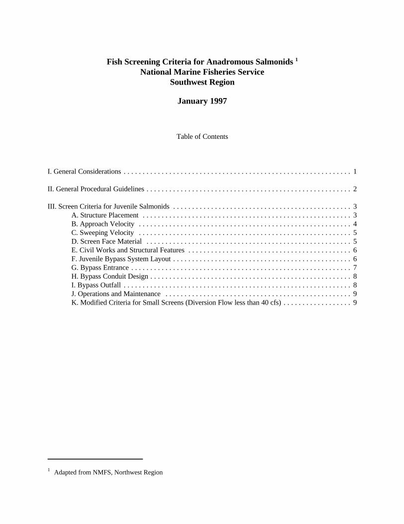
Fish Screening Criteria for Anadromous Salmonids 1
National Marine Fisheries ServiceSouthwest Region
January 1997
Table of Contents
I. General Considerations . . . . . . . . . . . . . . . . . . . . . . . . . . . . . . . . . . . . . . . . . . . . . . . . . . . . . . . . . . . . 1
II. General Procedural Guidelines . . . . . . . . . . . . . . . . . . . . . . . . . . . . . . . . . . . . . . . . . . . . . . . . . . . . . . 2
III. Screen Criteria for Juvenile Salmonids . . . . . . . . . . . . . . . . . . . . . . . . . . . . . . . . . . . . . . . . . . . . . . . 3A. Structure Placement . . . . . . . . . . . . . . . . . . . . . . . . . . . . . . . . . . . . . . . . . . . . . . . . . . . . . . . 3B. Approach Velocity . . . . . . . . . . . . . . . . . . . . . . . . . . . . . . . . . . . . . . . . . . . . . . . . . . . . . . . . 4C. Sweeping Velocity . . . . . . . . . . . . . . . . . . . . . . . . . . . . . . . . . . . . . . . . . . . . . . . . . . . . . . . . 5D. Screen Face Material . . . . . . . . . . . . . . . . . . . . . . . . . . . . . . . . . . . . . . . . . . . . . . . . . . . . . . 5E. Civil Works and Structural Features . . . . . . . . . . . . . . . . . . . . . . . . . . . . . . . . . . . . . . . . . . . 6F. Juvenile Bypass System Layout . . . . . . . . . . . . . . . . . . . . . . . . . . . . . . . . . . . . . . . . . . . . . . . 6G. Bypass Entrance . . . . . . . . . . . . . . . . . . . . . . . . . . . . . . . . . . . . . . . . . . . . . . . . . . . . . . . . . . 7H. Bypass Conduit Design . . . . . . . . . . . . . . . . . . . . . . . . . . . . . . . . . . . . . . . . . . . . . . . . . . . . . 8I. Bypass Outfall . . . . . . . . . . . . . . . . . . . . . . . . . . . . . . . . . . . . . . . . . . . . . . . . . . . . . . . . . . . . 8J. Operations and Maintenance . . . . . . . . . . . . . . . . . . . . . . . . . . . . . . . . . . . . . . . . . . . . . . . . . 9K. Modified Criteria for Small Screens (Diversion Flow less than 40 cfs) . . . . . . . . . . . . . . . . . . 9
NMFS Fish Screen Criteria 1
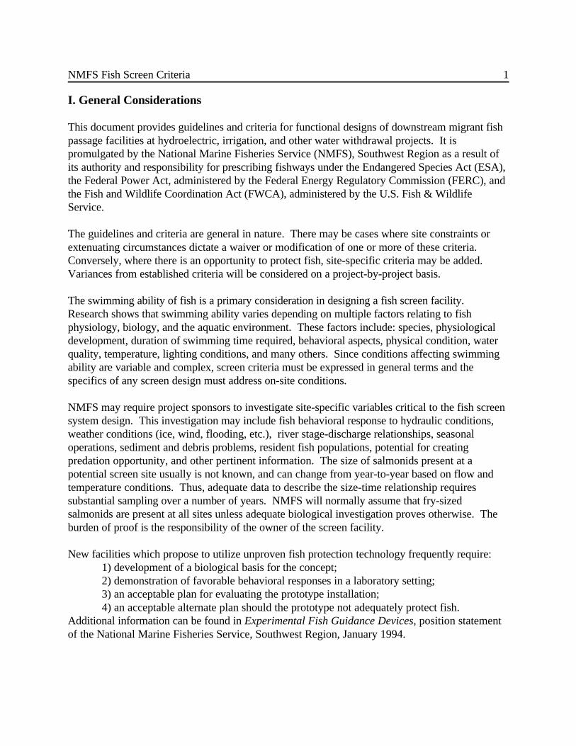
I. General Considerations
This document provides guidelines and criteria for functional designs of downstream migrant fishpassage facilities at hydroelectric, irrigation, and other water withdrawal projects. It ispromulgated by the National Marine Fisheries Service (NMFS), Southwest Region as a result ofits authority and responsibility for prescribing fishways under the Endangered Species Act (ESA),the Federal Power Act, administered by the Federal Energy Regulatory Commission (FERC), andthe Fish and Wildlife Coordination Act (FWCA), administered by the U.S. Fish & WildlifeService.
The guidelines and criteria are general in nature. There may be cases where site constraints orextenuating circumstances dictate a waiver or modification of one or more of these criteria.Conversely, where there is an opportunity to protect fish, site-specific criteria may be added. Variances from established criteria will be considered on a project-by-project basis.
The swimming ability of fish is a primary consideration in designing a fish screen facility. Research shows that swimming ability varies depending on multiple factors relating to fishphysiology, biology, and the aquatic environment. These factors include: species, physiologicaldevelopment, duration of swimming time required, behavioral aspects, physical condition, waterquality, temperature, lighting conditions, and many others. Since conditions affecting swimmingability are variable and complex, screen criteria must be expressed in general terms and thespecifics of any screen design must address on-site conditions.
NMFS may require project sponsors to investigate site-specific variables critical to the fish screensystem design. This investigation may include fish behavioral response to hydraulic conditions,weather conditions (ice, wind, flooding, etc.), river stage-discharge relationships, seasonaloperations, sediment and debris problems, resident fish populations, potential for creatingpredation opportunity, and other pertinent information. The size of salmonids present at apotential screen site usually is not known, and can change from year-to-year based on flow andtemperature conditions. Thus, adequate data to describe the size-time relationship requiressubstantial sampling over a number of years. NMFS will normally assume that fry-sizedsalmonids are present at all sites unless adequate biological investigation proves otherwise. Theburden of proof is the responsibility of the owner of the screen facility.
New facilities which propose to utilize unproven fish protection technology frequently require: 1) development of a biological basis for the concept;2) demonstration of favorable behavioral responses in a laboratory setting;3) an acceptable plan for evaluating the prototype installation;4) an acceptable alternate plan should the prototype not adequately protect fish.
Additional information can be found in Experimental Fish Guidance Devices, position statementof the National Marine Fisheries Service, Southwest Region, January 1994.
NMFS Fish Screen Criteria 2
Striped Bass, Herring, Shad, Cyprinids, and other anadromous fish species may have eggs and/orvery small fry which are moved with any water current (tides, streamflows, etc.). Installationswhere these species are present may require individual evaluation of the proposed project usingmore conservative screening requirements. In instances where state or local regulatory agenciesrequire more stringent screen criteria to protect species other than salmonids, NMFS willgenerally defer to the more conservative criteria.
General screen criteria and procedural guidelines are provided below. Specific exceptions tothese criteria occur in the design of small screen systems (less than 40 cubic feet per second) andcertain small pump intakes. These exceptions are listed in Section K, Modified Criteria for SmallScreens, and in the separate addendum entitled: Juvenile Fish Screen Criteria For Pump Intakes,National Marine Fisheries Service, Portland, Oregon, May 9, 1996.
II. General Procedural Guidelines
For projects where NMFS has jurisdiction, such as FERC license applications and ESAconsultations, a functional design must be developed as part of the application or consultation.These designs must reflect NMFS design criteria and be acceptable to NMFS. Acceptable designstypically define type, location, method of operation, and other important characteristics of the fishscreen facility. Design drawings should show structural dimensions in plan, elevation, and cross-sectional views, along with important component details. Hydraulic information should include:hydraulic capacity, expected water surface elevations, and flows through various areas of thestructures. Documentation of relevant hydrologic information is required. Types of materialsmust be identified where they will directly affect fish. A plan for operations and maintenanceprocedures should be included- i.e., preventive and corrective maintenance procedures,inspections and reporting requirements, maintenance logs, etc.- particularly with respect to debris,screen cleaning, and sedimentation issues. The final detailed design shall be based on thefunctional design, unless changes are agreed to by NMFS.
All juvenile passage facilities shall be designed to function properly through the full range ofhydraulic conditions expected at a particular project site during fish migration periods, and shallaccount for debris and sedimentation conditions which may occur.
NMFS Fish Screen Criteria 3
III. Screen Criteria for Juvenile Salmonids
A. Structure Placement
1. General:
The screened intake shall be designed to withdraw water from the most appropriate elevation,considering juvenile fish attraction, appropriate water temperature control downstream or acombination thereof. The design must accommodate the expected range of water surfaceelevations.
For on-river screens, it is preferable to keep the fish in the main channel rather than put themthrough intermediate screen bypasses. NMFS decides whether to require intermediate bypassesfor on-river, straight profile screens by considering the biological and hydraulic conditions existingat each individual project site.
2. Streams and Rivers:
Where physically practical, the screen shall be constructed at the diversion entrance. The screenface should be generally parallel to river flow and aligned with the adjacent bankline. A smoothtransition between the bankline and the screen structure is important to minimize eddies andundesirable flow patterns in the vicinity of the screen. If trash racks are used, sufficient hydraulicgradient is required to route juvenile fish from between the trashrack and screens to safety. Physical factors that may preclude screen construction at the diversion entrance include excessriver gradient, potential for damage by large debris, and potential for heavy sedimentation. Largestream-side installations may require intermediate bypasses along the screen face to preventexcessive exposure time. The need for intermediate bypasses shall be decided on a case-by-casebasis.
2. Canals:
Where installation of fish screens at the diversion entrance is undesirable or impractical, thescreens may be installed at a suitable location downstream of the canal entrance. All screensdownstream of the diversion entrance shall provide an effective juvenile bypass system- designedto collect juvenile fish and safely transport them back to the river with minimum delay. The angleof the screen to flow should be adequate to effectively guide fish to the bypass. Juvenile bypasssystems are part of the overall screen system and must be accepted by NMFS.
NMFS Fish Screen Criteria 4
Other species may require different approach velocity standards, e.g.- in California, the U.S. Fish & Wildlife 2
Service requires 0.2 fps approach velocity where delta smelt are present in the tidal areas of the San Francisco Bayestuary.
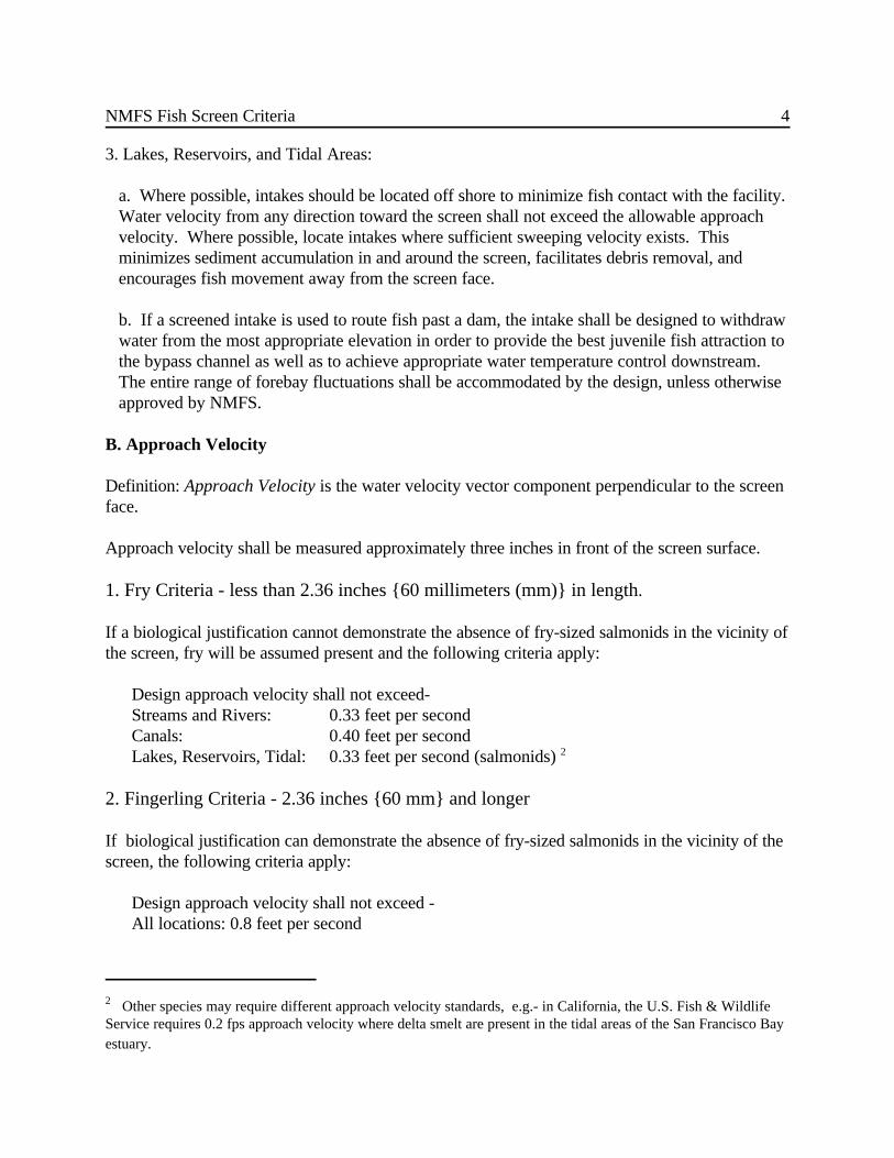
3. Lakes, Reservoirs, and Tidal Areas:
a. Where possible, intakes should be located off shore to minimize fish contact with the facility. Water velocity from any direction toward the screen shall not exceed the allowable approachvelocity. Where possible, locate intakes where sufficient sweeping velocity exists. Thisminimizes sediment accumulation in and around the screen, facilitates debris removal, andencourages fish movement away from the screen face.
b. If a screened intake is used to route fish past a dam, the intake shall be designed to withdrawwater from the most appropriate elevation in order to provide the best juvenile fish attraction tothe bypass channel as well as to achieve appropriate water temperature control downstream. The entire range of forebay fluctuations shall be accommodated by the design, unless otherwiseapproved by NMFS.
B. Approach Velocity
Definition: Approach Velocity is the water velocity vector component perpendicular to the screenface.
Approach velocity shall be measured approximately three inches in front of the screen surface.
1. Fry Criteria - less than 2.36 inches {60 millimeters (mm)} in length.
If a biological justification cannot demonstrate the absence of fry-sized salmonids in the vicinity ofthe screen, fry will be assumed present and the following criteria apply:
Design approach velocity shall not exceed-Streams and Rivers: 0.33 feet per second Canals: 0.40 feet per secondLakes, Reservoirs, Tidal: 0.33 feet per second (salmonids) 2
2. Fingerling Criteria - 2.36 inches {60 mm} and longer
If biological justification can demonstrate the absence of fry-sized salmonids in the vicinity of thescreen, the following criteria apply:
Design approach velocity shall not exceed -All locations: 0.8 feet per second
NMFS Fish Screen Criteria 5
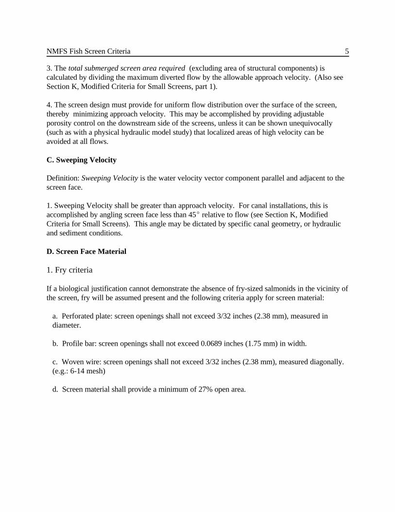
3. The total submerged screen area required (excluding area of structural components) iscalculated by dividing the maximum diverted flow by the allowable approach velocity. (Also seeSection K, Modified Criteria for Small Screens, part 1).
4. The screen design must provide for uniform flow distribution over the surface of the screen,thereby minimizing approach velocity. This may be accomplished by providing adjustableporosity control on the downstream side of the screens, unless it can be shown unequivocally(such as with a physical hydraulic model study) that localized areas of high velocity can beavoided at all flows.
C. Sweeping Velocity
Definition: Sweeping Velocity is the water velocity vector component parallel and adjacent to thescreen face.
1. Sweeping Velocity shall be greater than approach velocity. For canal installations, this isaccomplished by angling screen face less than 45E relative to flow (see Section K, ModifiedCriteria for Small Screens). This angle may be dictated by specific canal geometry, or hydraulicand sediment conditions.
D. Screen Face Material
1. Fry criteria
If a biological justification cannot demonstrate the absence of fry-sized salmonids in the vicinity ofthe screen, fry will be assumed present and the following criteria apply for screen material:
a. Perforated plate: screen openings shall not exceed 3/32 inches (2.38 mm), measured in diameter.
b. Profile bar: screen openings shall not exceed 0.0689 inches (1.75 mm) in width.
c. Woven wire: screen openings shall not exceed 3/32 inches (2.38 mm), measured diagonally. (e.g.: 6-14 mesh)
d. Screen material shall provide a minimum of 27% open area.

NMFS Fish Screen Criteria 6
2. Fingerling Criteria
If biological justification can demonstrate the absence of fry-sized salmonids in the vicinity of thescreen, the following criteria apply for screen material:
a. Perforated plate: Screen openings shall not exceed 1/4 inch (6.35 mm) in diameter.
b. Profile bar: screen openings shall not exceed 1/4 inch (6.35 mm) in width
c. Woven wire: Screen openings shall not exceed 1/4 inch (6.35 mm) in the narrow direction
d. Screen material shall provide a minimum of 40% open area.
3. The screen material shall be corrosion resistant and sufficiently durable to maintain a smoothand uniform surface with long term use.
E. Civil Works and Structural Features
1. The face of all screen surfaces shall be placed flush with any adjacent screen bay, pier noses,and walls, allowing fish unimpeded movement parallel to the screen face and ready access tobypass routes.
2. Structural features shall be provided to protect the integrity of the fish screens from largedebris. Trash racks, log booms, sediment sluices, or other measures may be needed. A reliableon-going preventive maintenance and repair program is necessary to ensure facilities are kept freeof debris and the screen mesh, seals, drive units, and other components are functioning correctly.
3. Screens located in canals - surfaces shall be constructed at an angle to the approaching flow,with the downstream end terminating at the bypass system entrance.
4. The civil works design shall attempt to eliminate undesirable hydraulic effects (e.g.- eddies,stagnant flow zones) that may delay or injure fish, or provide predator opportunities. Upstreamtraining wall(s), or some acceptable variation thereof, shall be utilized to control hydraulicconditions and define the angle of flow to the screen face. Large facilities may require hydraulicmonitoring to identify and correct areas of concern.
F. Juvenile Bypass System Layout
Juvenile bypass systems are water channels which transport juvenile fish from the face of a screento a relatively safe location in the main migratory route of the river or stream. Juvenile bypasssystems are necessary for screens located in canals because anadromous fish must be routed backto their main migratory route. For other screen locations and configurations, NMFS accepts the
NMFS Fish Screen Criteria 7
In California, 60 second exposure time applies to screens in canals, using a 0.4 fps approach velocity. Where3
more conservative approach velocities are used, longer exposure times may be approved on a case-by-case basis,and exceptions to established criteria shall be treated as variances.
option which, in its judgement, provides the highest degree of fish protection given existing siteand project constraints.
1. The screen and bypass shall work in tandem to move out-migrating salmonids (includingadults) to the bypass outfall with minimum injury or delay. Bypass entrance(s) shall be designedsuch that out-migrants can easily locate and enter them. Screens installed in canal diversions shallbe constructed with the downstream end of the screen terminating at a bypass entrance. Multiplebypass entrances (intermediate bypasses) shall be employed if the sweeping velocity will notmove fish to the bypass within 60 seconds assuming the fish are transported at this velocity. 3
Exceptions will be made for sites without satisfactory hydraulic conditions, or for screens built onriver banks with satisfactory river conditions.
2. All components of the bypass system, from entrance to outfall, shall be of sufficient hydrauliccapacity to minimize the potential for debris blockage.
3. To improve bypass collection efficiency for a single bank of vertically oriented screens, abypass training wall may be located at an angle to the screens.
4. In cases where insufficient flow is available to satisfy hydraulic requirements at the main bypassentrance(s), a secondary screen may be required. Located in the main screen’s bypass channel, asecondary screen allows the prescribed bypass flow to be used to effectively attract fish into thebypass entrance(s) while allowing all but a reduced residual bypass flow to be routed back (bypump or gravity) for the primary diversion use. The residual bypass flow (not passing through thesecondary screen) then conveys fish to the bypass outfall location or other destination.
5. Access is required at locations in the bypass system where debris accumulation may occur.
6. The screen civil works floor shall allow fish to be routed to the river safely in the event thecanal is dewatered. This may entail a sumped drain with a small gate and drain pipe, or similarprovisions.
G. Bypass Entrance
1. Each bypass entrance shall be provided with independent flow control, acceptable to NMFS.
2. Bypass entrance velocity must equal or exceed the maximum velocity vector resultant along thescreen, upstream of the entrance. A gradual and efficient acceleration into the bypass is requiredto minimize delay of out-migrants.
NMFS Fish Screen Criteria 8
3. Ambient lighting conditions are required from the bypass entrance to the bypass flow control.
4. The bypass entrance must extend from floor to water surface.
H. Bypass Conduit Design
1. Smooth interior pipe surfaces and conduit joints shall be required to minimize turbulence,debris accumulation, and the risk of injury to juvenile fish. Surface smoothness must beacceptable to the NMFS.
2. Fish shall not free-fall within a confined shaft in a bypass system.
3. Fish shall not be pumped within the bypass system.
4. Pressure in the bypass pipe pipe shall be equal to or above atmospheric pressure.
5. Extreme bends shall be avoided in the pipe layout to avoid excessive physical contact betweensmall fish and hard surfaces and to minimize debris clogging . Bypass pipe centerline radius ofcurvature (R/D) shall be 5 or greater. Greater R/D may be required for supercritical velocities.
6. Bypass pipes or open channels shall be designed to minimize debris clogging and sedimentdeposition and to facilitate cleaning. Pipe diameter shall be 24 inches (0.610 m) or greater andpipe velocity shall be 2.0 fps (0.610 mps) or greater, unless otherwise approved by NMFS. (SeeModified Criteria for Small Screens) for the entire operational range.
7. No closure valves are allowed within bypass pipes.
8. Depth of flow in a bypass conduit shall be 0.75 ft. (0.23 m) or greater, unless otherwiseauthorized by NMFS (See Modified Criteria for Small Screens).
9. Bypass system sampling stations shall not impair normal operation of the screen facility.
10. No hydraulic jumps should exist within the bypass system.
I. Bypass Outfall
1. Ambient river velocities at bypass outfalls should be greater than 4.0 fps (1.2 mps), or as closeas obtainable.
2. Bypass outfalls shall be located and designed to minimize avian and aquatic predation in areasfree of eddies, reverse flow, or known predator habitat.
NMFS Fish Screen Criteria 9
3. Bypass outfalls shall be located where there is sufficient depth (depending on the impactvelocity and quantity of bypass flow) to avoid fish injuries at all river and bypass flows.
4. Impact velocity (including vertical and horizontal components) shall not exceed 25.0 fps (7.6mps).
5. Bypass outfall discharges shall be designed to avoid adult attraction or jumping injuries.
J. Operations and Maintenance
1. Fish Screens shall be automatically cleaned as frequently as necessary to prevent accumulationof debris. The cleaning system and protocol must be effective, reliable, and satisfactory to NMFS. Proven cleaning technologies are preferred.
2. Open channel intakes shall include a trash rack in the screen facility design which shall be keptfree of debris. In certain cases, a satisfactory profile bar screen design can substitute for a trashrack.
3. The head differential to trigger screen cleaning for intermittent type systems shall be amaximum of 0.1 feet (.03 m), unless otherwise agreed to by NMFS.
4. The completed screen and bypass facility shall be made available for inspection by NMFS, toverify compliance with design and operational criteria.
5. Screen and bypass facilities shall be evaluated for biological effectiveness and to verify thathydraulic design objectives are achieved.
K. Modified Criteria for Small Screens (Diversion Flow less than 40 cfs)
The following criteria vary from the standard screen criteria listed above. These criteriaspecifically apply to lower flow, surface-oriented screens (e.g.- small rotating drum screens). Forty cfs is the approximate cut off; however, some smaller diversions may be required to applythe general criteria listed above, while some larger diversions may be allowed to use the “smallscreen” criteria below. NMFS will decide on a case-by-case basis depending on site constraints.
1. The required screen area is a function of the approach velocity listed in Section B, ApproachVelocity, Parts 1, 2, and 3 above. Note that “maximum” refers to the greatest flow diverted, notnecessarily the water right.
2. Screen Orientation:
a. For screen lengths six feet or less, screen orientation may be angled perpendicular to theflow.
NMFS Fish Screen Criteria 10
b. For screen lengths greater than six feet, screen-to-flow angle must be less than 45 degrees.(See Section C Sweeping Velocity, part 1).
c. For drum screens, design submergence shall be 75% of drum diameter. Submergence shallnot exceed 85%, nor be less than 65% of drum diameter.
d. Minimum bypass pipe diameter shall be 10 in (25.4 cm), unless otherwise approved by NMFS.
e. Minimum pipe depth is 1.8 in (4.6 cm) and is controlled by designing the pipe gradient forminimum bypass flow.
Questions concerning this document can be directed to NMFS Hydraulic Engineering Staff at:
National Marine Fisheries ServiceSouthwest Region777 Sonoma Ave. Room 325Santa Rosa, CA 95402Phone: 707-575-6050
Adopted,
Date:
Authorizing Signature:
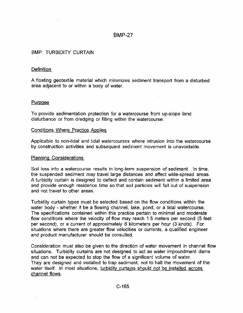
BMP-27
BMP: TURBIDITY CURTAIN
Definition
A floating geotextile material which minimizes sediment transport from a disturbed area adjacent to or within a body of water.
Purpose
To provide sedimentation protection for a watercourse from up-slope land disturbance or from dredging or filling within the watercourse.
Conditions Where Practice Applies
Applicable to non-tidal and tidal watercourses where intrusion into the watercourse by construction activities and subsequent sediment movement is unavoidable.
Planning Considerations
Soil loss into a watercourse results in long-term suspension of sediment. In time, the suspended sediment may travel large distances and affect wide-spread areas. A turbidity curtain is designed to deflect and contain sediment within a limited area and provide enough residence time so that soil particles will fall out of suspension and not travel to other areas.
Turbidity curtain types must be selected based on the flow conditions within the water body -whether it be a flowing channel, lake, pond, or a tidal watercourse. The specifications contained within this practice pertain to minimal and moderate flow conditions where the velocity of flow may reach 1.5 meters per second (5 feet per second), or a current of approximately 6 kilometers per hour (3 knots). For situations where there are greater flow velocities or currents, a qualified engineer and product manufacturer should be consulted.
Consideration must also be given to the direction of water movement in channel flow situations. Turbidity curtains are not designed to act as water impoundment dams and can not be expected to stop the flow of a significant volume of water. They are designed and installed to trap sediment, not to halt the movement of the water itself. In most situations, turbidity curtains should not be installed across channel flows.
C-165
In tidal or moving water conditions, provisions must be made to allow the volume of water contained within the curtain to change. Since the bottom of the curtain is weighted and external anchors are frequently added, the volume of water contained within the curtain will be much greater at high tide verses low tide and measures must be taken to prevent the curtain from submerging. In addition to allowing for slack in the curtain to rise and fall, water must be allowed to flow through the curtain if the curtain is to remain in roughly the same spot and to maintain the same shape. Normally, this is achieved by constructing part of the curtain from a heavy woven filter fabric. The fabric allows the water to pass through the curtain, but retains the sediment pollutants. Consideration should be given to the volume of water that must pass through the fabric and sediment particle size when specifying fabric permeability.
Sediment which has been deflected and settled out by the curtain may be removed if so directed by the on-site inspector or the Plan-Approving Authority. However, consideration must be given to the probable outcome of the procedure -will it create more of a sediment problem resuspension of particles and by accidental dumping of the material by the equipment involved? It is, therefore, recommended that the soil particles trapped by a turbidity curtain only be removed if there has been a significant change in the original contours of the affected area in the watercourse. Regardless of the decision made, soil particles should always be allowed to settle for a minimum of 6-12 hours prior to their removal by equipment or prior to removal of a turbidity curtain.
It is imperative that the intended function of the other controls in this chapter, to sediment out of the watercourse, be the strategy used in every erosion control plan. However, when proximity to the watercourse makes successfully mitigating sediment loss impossible, the use of the turbidity curtain during land disturbance is essential.
Design Criteria
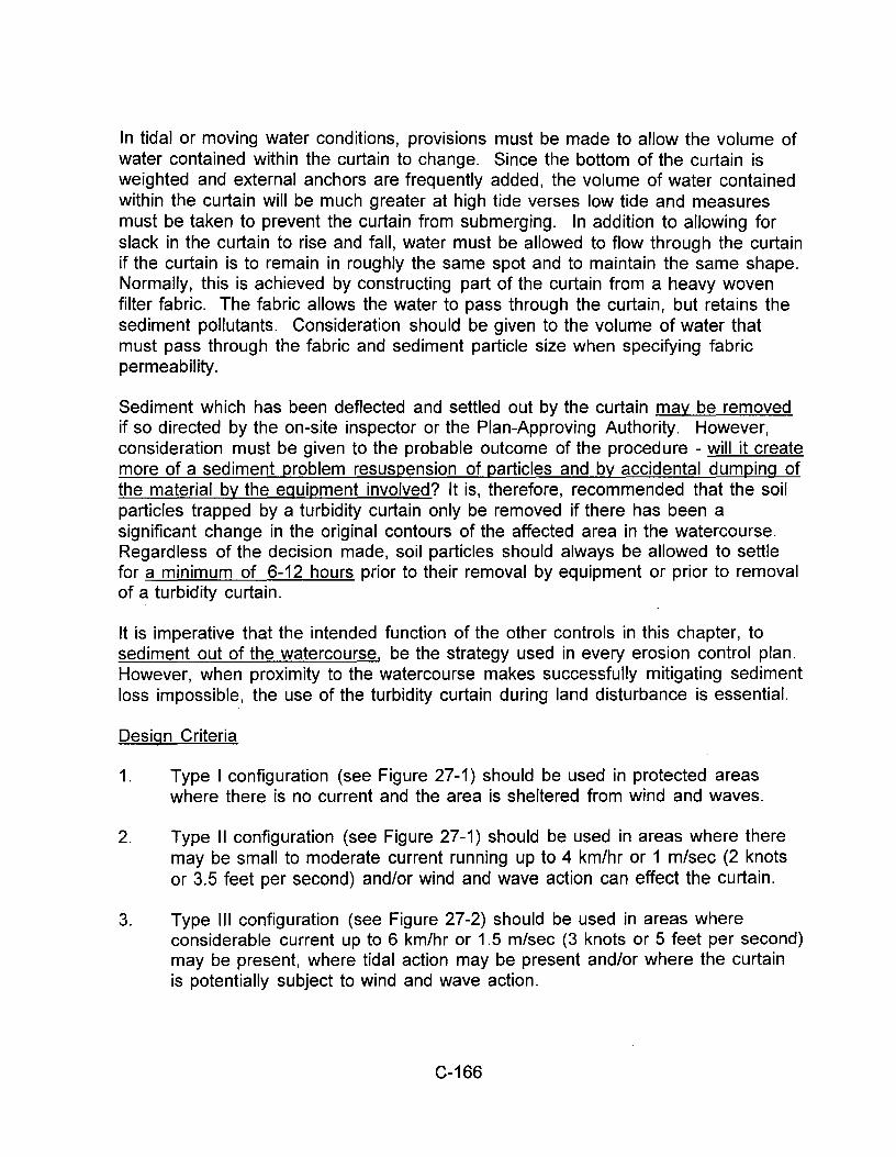
1. Type I configuration (see Figure 27-1) should be used in protected areas where there is no current and the area is sheltered from wind and waves.
2. Type II configuration (see Figure 27-1) should be used in areas where there may be small to moderate current running up to 4 km/hr or 1 m/sec (2 knots or 3.5 feet per second) and/or wind and wave action can effect the curtain.
3. Type Ill configuration (see Figure 27 -2) should be used in areas where considerable current up to 6 km/hr or 1.5 m/sec (3 knots or 5 feet per second) may be present, where tidal action may be present and/or where the curtain is potentially subject to wind and wave action.
C-166
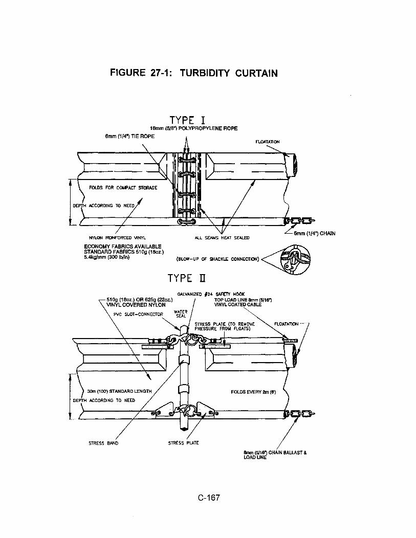
FIGURE 27-1: TURBIDITY CURTAIN
TYPE I 16mm (5/6') POLYPROPYLENE ROPE
6mm {1/4") TIE ROPE
F'OUlS F'OR COI.f'ACT STORAGE
NYlDN REINFORCED 'IIINYL
ECONOMY FABRICS AVAILABLE STANDARD FABRICS 610g (18oz.) 5.4kg/mm (300 lb/ln)
fl..O,t.TAllON
o\I..L SEMIS HEAT S!:Al.ED
(8L(JW-ue OF SOW:"-' COtKCTKlH) ~ TYPE Il
GALVANIZED f24- SAF'ElY HOOK 610g (16oz.) OR 625g (22oz.) TOP LOAD UNE Bmm (5/16") VINYL COVERED NYLON VINYL COATED CABLE
PVC SLOT-CONNECTO.R
DEPTH N:COROING TO NEED
STRESS BAND STRESS PLATE
C-167
FOLDS EVERY 2m (6')
Bmm (5/16') CHAIN BALLAST & LOAOUNE
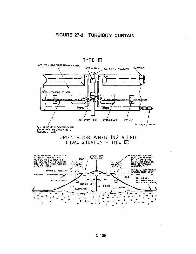
FIGURE 27-2: TURBIDITY CURTAIN
625g (22oz.) NYLON REINFORCE VINYL
8mm (5/16") VINYL COATED CABLE (ON BOTH SIDES OF CURTIN TO REDUCE STRAIN)
TYPE ill
ORIENTATION WHEN (TIDAL SITUATION
NOTE: ANCHORING WITH BUOYS, I>S SHOWN. REMOVES AU.. VERTICAL FORCES FROM 1HE CURTAIN. HENCE. THE CURTAIN ~ 1 fV"' WILL NOT SINK FROM WINO OR -.........: -CURRENT LOADS. v
600mm (2~ MIN.~ _
Q 0 c Q 0 0 Q 0
ATTACH UNES TO SHACKLE
Q 0 0 0
Q 00 0 Q 0 Q Q Q Q Q 0 0 <1 Q
Q Q 0 OQ Q 0 0 Q Q 0 Q 0 Q 0 0 0
0
C-168
8mm (5/16") CHAIN
INSTALLED TYPE 1Il)
,l.UTONAllC FlASHING UGHT (ON AT DUSKOFF AT DAWN) 1 00" ON CENTER SHALL BE USED tl N,l.VIGABLE CHANNELS ONLY
-+---- ST"-NDARO CONTAtiL4ENT SYSTENS UOHT BUOY
Q Q 0 0 Q
0 Q Q
0 Q Q 0 Q
Q Q Q Q q Q 0
Q Q
4. Turbidity curtains should extend the entire depth of the watercourse whenever the watercourse in question is not subject to tidal action and/or significant wind and wave forces.
5. In tidal and/or wind and wave action situations, the curtain should never be so long as to touch the bottom. A minimum 300 millimeter (1-foot) "gap" should exist between the weighted lower end of the skirt and the bottom at "mean" low water. Movement of the lower skirt over the bottom due to tidal reverses or wind and wave action on the flotation system may fan and stir sediments already settled out.
6. In tidal and/or wind and wave action situations, it is seldom practical to extend a turbidity curtain depth lower than 3 to 4 meters (1 0 to 12 feet) below the surface, even in deep water. Curtains which are installed deeper than this will be subject to very large loads with consequent strain on curtain materials and the mooring system. In addition, a curtain installed in such a manner can "billow up" towards the surface under the pressure of the moving water, which will result in an effective depth which is significantly less than the skirt depth.
7. Turbidity curtains should be located parallel to the direction of flow of a moving body of water. Turbidity Curtains should not be placed across the main flow of a significant body of moving water.
8. When sizing the length of the floating curtain, allow an additional 10-20% variance in the straight line measurements. This will allow for measuring errors, make installing easier and reduce stress from potential wave action during high winds.
9. An attempt should be made to avoid an excessive amount of joints in the curtain; a minimum continuous span of 15 meters (50 feet) between joints is a good "rule of thumb."
10. For stability reasons, a maximum span of 30 meters (1 00 feet) between joints (anchor or stake locations) is also a good rule to follow.
11. The ends of the curtain, both floating upper and weighted lower, should "tend well up into the shoreline, especially if high water conditions are expected. The ends should be secured firmly to the shoreline (preferably to rigid bodies such as trees or piles) to fully enclose the area where sediment may enter the water.
12. When there is a specific need to extend the curtain to the bottom of the watercourse in tidal or moving water conditions, a heavy woven pervious filter fabric may be substituted for the normally recommended impervious
C-169
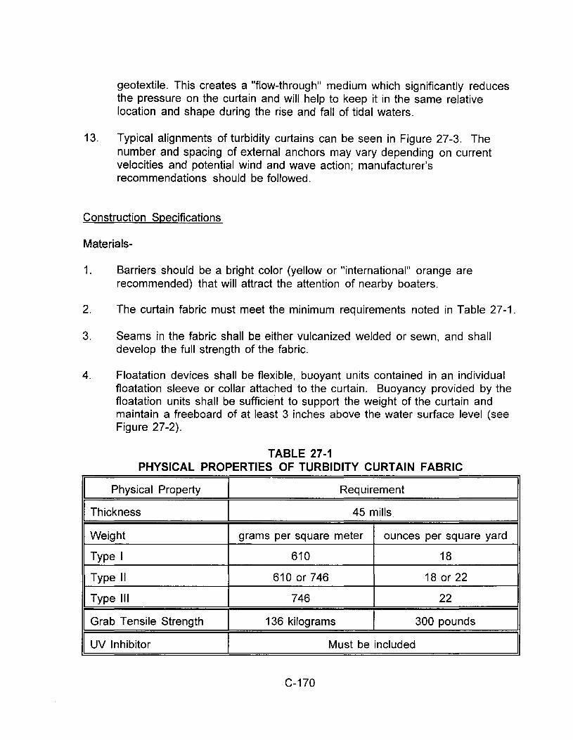
geotextile. This creates a "flow-through" medium which significantly reduces the pressure on the curtain and will help to keep it in the same relative location and shape during the rise and fall of tidal waters.
13. Typical alignments of turbidity curtains can be seen in Figure 27-3. The number and spacing of external anchors may vary depending on current velocities and potential wind and wave action; manufacturer's recommendations should be followed.
Construction Specifications
Materials-
1. Barriers should be a bright color (yellow or "international" orange are recommended) that will attract the attention of nearby boaters.
2. The curtain fabric must meet the minimum requirements noted in Table 27-1.
3. Seams in the fabric shall be either vulcanized welded or sewn, and shall develop the full strength of the fabric.
4. Floatation devices shall be flexible, buoyant units contained in an individual floatation sleeve or collar attached to the curtain. Buoyancy provided by the floatation units shall be sufficie.nt to support the weight of the curtain and maintain a freeboard of at least 3 inches above the water surface level (see Figure 27 -2).
TABLE 27-1 PHYSICAL PROPERTIES OF TURBIDITY CURTAIN FABRIC
I Physical Property I Requirement
I Thickness I 45 mills
Weight grams per square meter ounces per square yard
Type I 610 18
Type II 610 or 746 18 or 22
Type Ill 746 22
Grab Tensile Strength 136 kilograms 300 pounds
I UV Inhibitor I Must be included
C-170
I I
I
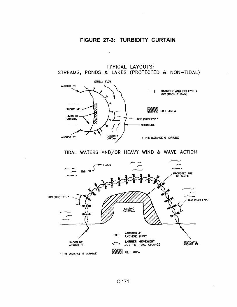
FIGURE 27-3: TURBIDITY CURTAIN
TYPICAL LAYOUTS: STREAMS, PONDS & LAKES (PROTECTED & NON-TIDAL)
-+ STAKE OR ANCHOR, EVERY 30m (100') (TYPICAL)
~riLL AREA
30m (100') TYP. •
• THIS DISTANCE IS VARIABLE
TIDAL WATERS AND/OR HEAVY WIND & WAVE ACTION
r-FlOOO
EBB__.)
SHORElJNE ANCHOR PT.
• THIS DISTANCE IS VARIABLE
<>
EXISTING CAUSEWAY
ANCHOR 8c ANCHOR BUOY
BARRIER MOVEMENT DUE TO TIDAL CHANGE
~ F"ILL AREA
C-171
-
SHORELINE ANCHOR PT.
5. Load lines must be fabricated into the bottom of all floating turbidity curtains. Type II and Type Ill must have load lines also fabricated into the top of the fabric. The top load line shall consist of woven webbing or vinyl-sheathed steel cable and shall have a break strength in excess of 4,500 kilograms (10,000 pounds). The supplemental (bottom) loadline shall consist of a chain incorporated into the bottom hem of the curtain of sufficient weight to serve as ballast to hold the curtain in a vertical position. Additional anchorage shall be provided as necessary. The load lines shall have suitable connecting devices which develop the full breaking strength for connecting to load lines in adjacent sections (see Figures 27-1 and 27-2 which portray this orientation).
6. External anchors may consist of wooden or metal stakes 50 x 100 millimeters (2 x 4 inch) or 60 millimeter (2.5-inch) minimum diameter wood or 2 kilogram per linear meter steel (1.33 pounds/linear foot) when Type I installation is used; when Type II or Type Ill installations are used, bottom anchors should be used.
7. Bottom anchors must be sufficient to hold the curtain in the same position relative to the bottom of the watercourse without interfering with the action of the curtain. The anchor may dig into the bottom (grappling hook, plow or fluke-type) or may be weighted (mushroom type) and should be attached to a floating anchor buoy via an anchor line. The anchor line would then run from the buoy to the top load line of the curtain. When used with Type Ill installations, these lines must contain enough slack to allow the buoy and curtain to float freely with tidal changes without pulling the buoy or curtain down and must be checked regularly to make sure they do not become entangled with debris. As previously noted, anchor spacing will vary with current velocity and potential wind and wave action; manufacturer's recommendations should be followed. See orientation of external anchors and anchor buoys for tidal installation in Figure 27-2.
Installation
1. In the calm water of lakes or ponds (Type I installation) it is usually sufficient to merely set the curtain end stakes or anchor points (using anchor buoys if bottom anchors are employed), then tow the curtain in the furled condition out and attach it to these stakes or anchor points. Following this, any additional stakes or buoyed anchors required to maintain the desired location of the curtain may be set and these anchor points made fast to the curtain. the furling lines should be cut to let the curtain skirt drop.
2. In rivers or in other moving water (Type II and Type Ill installations) it is important to set all the curtain anchor points. Care must be taken to ensure
C-172
that anchor points are of sufficient holding power to retain the curtain under the existing current conditions, prior to putting the furled curtain into the water. Again, anchor buoys should be employed on all anchors to prevent the current from submerging the flotation at the anchor points. If the moving water into which the curtain is being installed is tidal and will subject the curtain to currents in both directions as the tide changes, it is important to provide anchors on both sides of the curtain for two reasons:
a) Curtain movement will be minimized during tidal current reversals.
b) The curtain will not overrun the anchors and pull them out when the tide reverses.
When the anchors are secure, the furled curtain should be secured to the upstream anchor point and then sequentially attached to each next downstream anchor point until the entire curtain is in position. At this point, and before unfurling, the "lay" of the curtain should be assessed and any necessary adjustments made to the anchors. Finally, when the location is ascertained to be as desired, the furling lines should be cut to allow the skirt to drop.
3. Always attach anchor lines to the flotation device. not to the bottom of the curtain. The anchoring line attached to the floatation device on the downstream side will provide support for the curtain. Attaching the anchors to the bottom of the curtain could cause premature failure of the curtain due to the stresses imparted on the middle section of the curtain.
4. There is an exception to the rule that turbidity curtains should not be installed across channel flows; it occurs when there is a danger of creating a silt buildup in the middle of a watercourse, thereby blocking access or creating a sand bar. Curtains have been used effectively in large areas of moving water by forming a very long sided, sharp "V" to deflect clean water around a work site, confine a large part of the silt-laden water to the work area inside the "V' and direct much of the silt toward the shoreline. Care must be taken, however, not to install the curtain perpendicular to the water current.
5. See Figure 27-3 for typical installation layouts.
C-173
Removal
1. Care should be taken to protect the skirt from damage as the turbidity curtain is dragged from the water.
2. The site selected to bring the curtain ashore should be free of sharp rocks, broken cement, debris, etc. so as to minimize damage when hauling the curtain over the area.
3. If the curtain has a deep skirt, it can be further protected by running a small boat along its length with a crew installing furling lines before attempting to remove the curtain from the water.
Maintenance
1. The developer/owner shall be responsible for maintenance of the filter curtain for the duration of the project in order to ensure the continuous protection of the watercourse.
2. Should repairs to the geotextile fabric become necessary, there are normally repair kits available from the manufacturers; manufacturer's instructions must be followed to ensure the adequacy of the repair.
3. When the curtain is no longer required as determined by the inspector, the curtain and related components shall be removed in such a manner as to minimize turbidity. Remaining sediment shall be sufficiently settled before removing the curtain. Sediment may be removed and the original depth (or plan elevation) restored. Any spoils must be taken to upland area and be stabilized.
C-174
1
Attachment G: Monitoring Plan
I. Visual Monitoring (Inspection) Requirements for Qualifying Rain Events This site has been identified as Risk Level 2. Monitoring is in compliance with Construction General Permit requirements for that risk level.
A. Contractor will visually observe (inspect) storm water discharges at all discharge
locations within two business days (48 hours) after each qualifying rain event. B. Contractor will visually observe (inspect) the discharge of stored or contained
storm water that is derived from and discharged subsequent to a qualifying rain event producing precipitation of ½ inch or more at the time of discharge. Stored or contained storm water that will likely discharge after operating hours due to anticipated precipitation will be observed prior to the discharge during operating hours.
C. Contractor will conduct visual observations (inspections) during business hours only.
D. Contractor will record the time, date and rain gauge reading of all qualifying rain events.
E. Within 2 business days (48 hours) prior to each qualifying rain event, Contractor will visually observe (inspect) all storm water drainage areas to identify any spills, leaks, or uncontrolled pollutant sources. If needed, the Contractor will implement appropriate corrective actions. All Best Management Practices (BMPs) will be inspected whether they have been properly implemented in accordance with the Stormwater Pollution Prevention Plan/Rain Event Action Plan (SWPPP/REAP). If needed, the Contractor will implement appropriate corrective actions. Any storm water storage and containment areas to detect leaks and ensure maintenance of adequate freeboard.
F. For the visual observations (inspections), Contractor will observe the presence or absence of floating and suspended materials, sheen on the surface, discolorations, turbidity, odors, and source of any observed pollutants.
G. Within two business days (48 hours) after each qualifying rain event, Contractor will conduct post rain event visual observations (inspections) to identify whether BMPs were adequately designed, implemented, and effective, and identify additional BMPs and revise the SWPPP accordingly.
H. Contractor will maintain on-site records of all visual observations (inspections), personnel performing the observations, observation dates, weather conditions, locations observed, and corrective actions taken in response to the observations.
II. Water Quality Sampling and Analysis
A. Contractor will collect storm water grab samples from sampling locations. The
storm water grab sample(s) obtained will be representative of the flow and characteristics of the discharge.
B. At minimum, Contractor will collect 3 samples per day of the qualifying event. C. Contractor will ensure that the grab samples collected of stored or contained
storm water are from discharges subsequent to a qualifying rain event (producing precipitation of ½ inch or more at the time of discharge). Storm Water Effluent Monitoring requirements
D. Contractor will analyze their effluent samples for:
2
i. PH and turbidity. ii. Any additional parameters for which monitoring are required by the
Regional Water Board, such as dissolved sulfide, dissolved oxygen.
III. Storm Water Discharge Water Quality Sampling Locations
A. Contractor will perform sampling and analysis of storm water discharges to characterize discharges associated with construction activity from the entire project disturbed area.
B. Contractor will collect effluent samples at all discharge points where storm water is discharged off-site.
C. Contractor will ensure that storm water discharge collected and observed represent the effluent in each drainage area based on visual observation of the water and upstream conditions.
D. Contractor will monitor and report site run-on from surrounding areas if there is reason to believe run-on may contribute to an exceedance of Numerical Action Limits (NALs).
E. Contractor will select analytical test methods from the list provided in section VII below.
F. All storm water sample collection preservation and handling will be conducted in accordance with Section V. “Storm Water Sample Collection and Handling Instructions” below.
IV. Visual Observation and Sample Collection Exemptions
A. Contractor will be prepared to collect samples and conduct visual observation
(inspections). Contractor are not required to physically collect samples or conduct visual observation (inspections) under the following conditions:
For example, if there has been concrete work recently in an area, or drywall scrap is exposed to the rain, a pH sample will be taken of drainage from the relevant work area. Similarly, if sediment laden water is flowing through some parts of a silt fence, samples will be taken of the sediment-laden water even if most water flowing through the fence is clear.
i. During dangerous weather conditions such as flooding and electrical storms.
ii. Outside of scheduled site business hours.
B. If no required samples or visual observation (inspections) are collected due to these exceptions, Contractor will include an explanation in their SWPPP and in the Annual Report documenting why the sampling or visual observation (inspections) were not conducted.
V. Storm Water Sample Collection and Handling Instructions
A. Contractor will refer to Table 1 below for test methods, detection limits, and reporting units.
3
B. Contractor will ensure that testing laboratories will receive samples within 48 hours of the physical sampling (unless otherwise required by the laboratory), and will use only the sample containers provided by the laboratory to collect and store samples.
C. Contractor will designate and train personnel to collect, maintain, and ship samples in accordance with the Surface Water Ambient Monitoring Program’s (SWAMP) 2008 Quality Assurance Program Plan (QAPrP).
VI. Monitoring Methods
A. Contractor will include a description of the following items in the CSMP: i. Visual observation locations, visual observation procedures, and visual
observation follow-up and tracking procedures. ii. Sampling locations, and sample collection and handling procedures. This
will include detailed procedures for sample collection, storage, preservation, and shipping to the testing lab to assure that consistent quality control and quality assurance is maintained. Contractor will attach to the monitoring program
iii. Identification of the analytical methods and related method detection limits (if applicable) for each parameter required in Section 7 above.
B. Contractor will ensure that all sampling and sample preservation are in accordance with the current edition of "Standard Methods for the Examination of Water and Wastewater" (American Public Health Association). All monitoring instruments and equipment (including a contractor’s own field instruments for measuring pH and turbidity) should be calibrated and maintained in accordance with manufacturers' specifications to ensure accurate measurements. Contractor will ensure that all laboratory analyses are conducted according to test procedures under 40 CFR Part 136, unless other test procedures have been specified in this General Permit or by the Regional Water Board. With the exception of field analysis conducted by the Contractor for turbidity and pH, all analyses should be sent to and conducted at a laboratory certified for such analyses by the State Department of Health Services. Contractor will conduct their own field analysis of pH and may conduct their own field analysis of turbidity if the Contractor has sufficient capability (qualified and trained employees, properly calibrated and maintained field instruments, etc.) to adequately perform the field analysis
VII. Analytical Methods
A. Contractor will refer to Table 1 below for test methods, detection limits, and reporting units.
i. pH: Contractor will perform pH analysis on-site with calibrated pH meter or a pH test kit. Contractor will record pH monitoring results on paper and retain these records in accordance with Section XII, below.
ii. Turbidity: Contractor will perform turbidity analysis using a calibrated turbidity meter, either on-site or at an accredited lab. Acceptable test methods include Standard Method 2130 or USEPA Method 180.1. The
4
results will be recorded in the site log book in Nephelometric Turbidity Units (NTU).
iii. Dissolved sulfide: Field test with calibrated portable instrument, not greater than 0.1 mg/L. Results will be recorded as below.
iv. Dissolved oxygen: Field test with calibrated portable instrument, 5.0 mg/l hourly average for discharge into tidal waters; 7.0 mg/l hourly average for discharge into non-tidal waters. Results will be recorded as below.
VIII. Non-Storm Water Discharge Monitoring Requirements
A. Visual Monitoring Requirements:
i. Contractor will visually observe (inspect) each drainage area for the
presence of (or indications of prior) unauthorized and authorized non-storm water discharges and their sources.
ii. Contractor will conduct one visual observation (inspection) quarterly in each of the following periods: January- March, April-June, July-September, and October-December. Visual observation (inspections) are only required during daylight hours (sunrise to sunset).
iii. Contractor will ensure that visual observations (inspections) document the presence or evidence of any nonstorm water discharge (authorized or unauthorized), pollutant characteristics (floating and suspended material, sheen, discoloration, turbidity, odor, etc.), and source. Contractor will maintain on-site records indicating the personnel performing the visual observation (inspections), the dates and approximate time each drainage area and non-storm water discharge was observed, and the response taken to eliminate unauthorized non-storm water discharges and to reduce or prevent pollutants from contacting non-storm water discharges.
B. Effluent Sampling Locations:
i. Contractor will sample effluent at all discharge points where non-storm water and/or authorized non-storm water is discharged off-site.
ii. Contractor will send all non-storm water sample analyses to a laboratory certified for such analyses by the State Department of Health Services.
iii. Contractor will monitor and report run-on from surrounding areas if there is reason to believe run-on may contribute to an exceedance of NALs.
IX. Non-Visible Pollutant Monitoring Requirements
A. Contractor will collect one or more samples during any breach, malfunction,
leakage, or spill observed during a visual inspection which could result in the discharge of pollutants to surface waters that would not be visually detectable in storm water.
B. Contractor will ensure that water samples are large enough to characterize the site conditions.
C. Contractor will collect samples at all discharge locations that can be safely accessed.
D. Contractor will collect samples during the first two hours of discharge from rain events that occur during business hours and which generate runoff.
5
E. Contractor will analyze samples for all non-visible pollutant parameters (if applicable) - parameters indicating the presence of pollutants identified in the pollutant source assessment required (Contractor will modify their CSMPs to address these additional parameters in accordance with any updated SWPPP pollutant source assessment).
F. Contractor will collect a sample of storm water that has not come in contact with the disturbed soil or the materials stored or used on-site (uncontaminated sample) for comparison with the discharge sample.
G. Contractor will compare the uncontaminated sample to the samples of discharge using field analysis or through laboratory analysis
H. Contractor will keep all field /or analytical data in the SWPPP document.
X. Records
A. Contractor will retain records of all storm water monitoring information and copies of all reports (including Annual Reports) for a period of at least three years. Contractor will retain all records on-site while construction is ongoing. These records include:
B. The date, place, time of facility inspections, sampling, visual observation (inspections), and/or measurements, including precipitation.
C. The individual(s) who performed the facility inspections, sampling, visual observation (inspections), and or measurements.
D. The date and approximate time of analyses. E. The individual(s) who performed the analyses. F. A summary of all analytical results from the last three years, the method
detection limits and reporting units, the analytical techniques or methods used, and the chain of custody forms.
G. Rain gauge readings from site inspections; H. Quality assurance/quality control records and results. I. Non-storm water discharge inspections and visual observation (inspections) and
storm water discharge visual observation records (see Sections I and VII above). J. Visual observation and sample collection exception records (see Section IV
above). K. The records of any corrective actions and follow-up activities that resulted from
analytical results, visual observation (inspections), or inspections.
XI. NAL Exceedance Report
A. In the event that any effluent sample exceeds an applicable NAL, Contractor will electronically submit all storm event sampling results to the State Water Board no later than 10 days after the conclusion of the storm event. The Regional Boards have the authority to require the submittal of an NAL Exceedance Report.
B. Contractor will certify each NAL Exceedance Report in accordance with the Special Provisions for Construction Activity.
C. Contractor will retain an electronic or paper copy of each NAL Exceedance Report for a minimum of three years after the date the annual report is filed.
D. Contractor will include in the NAL Exceedance Report:
i. The analytical method(s), method reporting unit(s), and method detection limit(s) of each analytical parameter (analytical results that are less than

6
the method detection limit will be reported as “less than the method detection limit”).
ii. The date, place, time of sampling, visual observation (inspections), and/or measurements, including precipitation.
iii. A description of the current BMPs associated with the effluent sample that exceeded the NAL and the proposed corrective actions taken.
Table 1: Risk Level 2 Test methods Detection Limits, Reporting Units and Applicable NALs/NELs Parameter Test Method /
Protocol Discharge Type
Min. Detection Limit
Reporting Units
Numeric Action Level
pH
Field test with calibrated portable
instrument
Risk Level 2 Discharges
0.2 pH units lower NAL = 6.5 upper NAL = 8.5
Turbidity
EPA 0180.1 and/or field test with calibrated
portable instrument
Risk Level 2 Discharges other than
ATS
1 NTU 250 NTU
For ATS discharges
1 NTU N/A
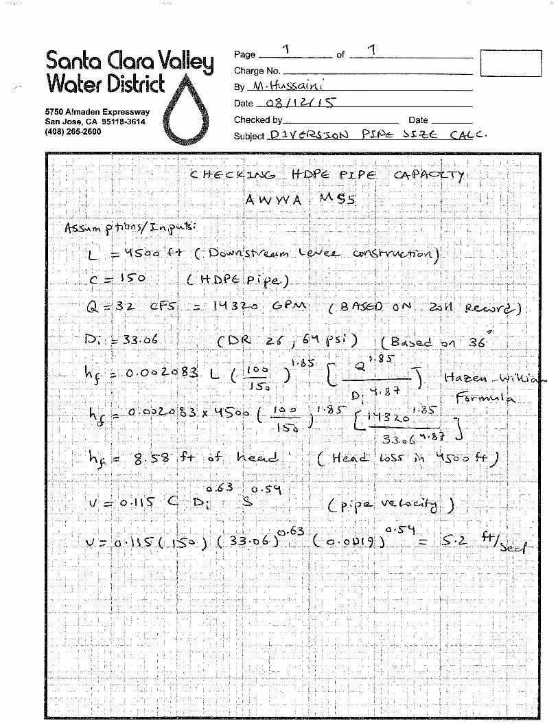
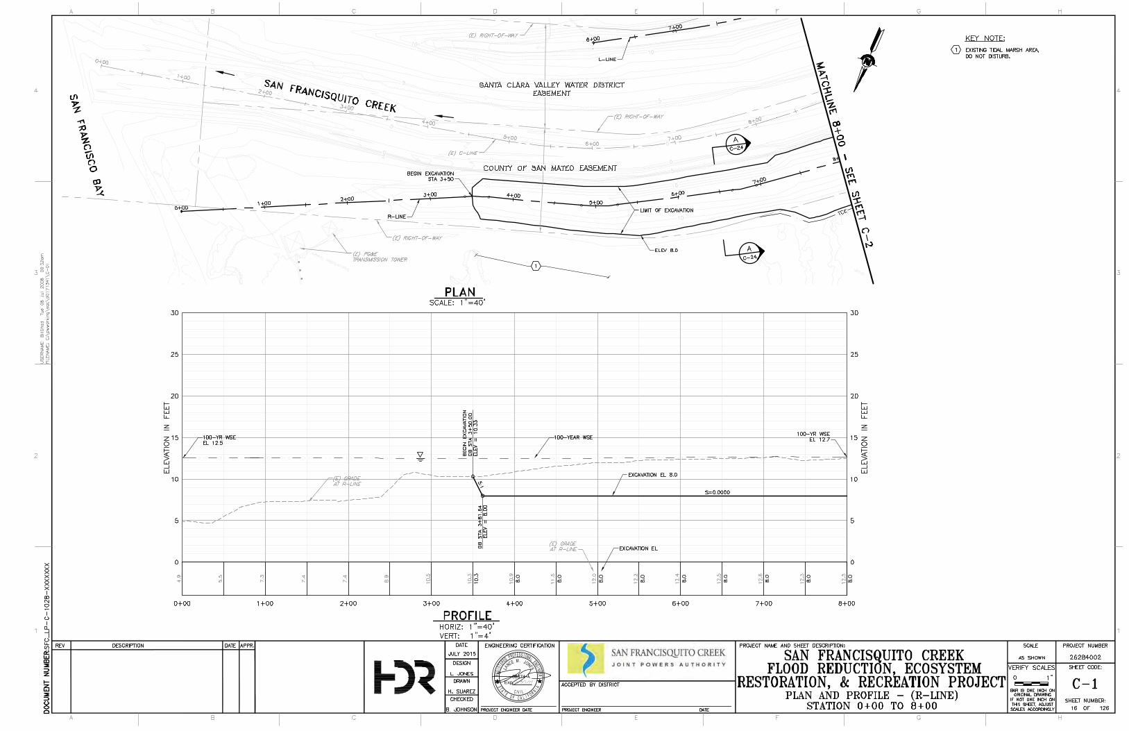
68374
Exp.
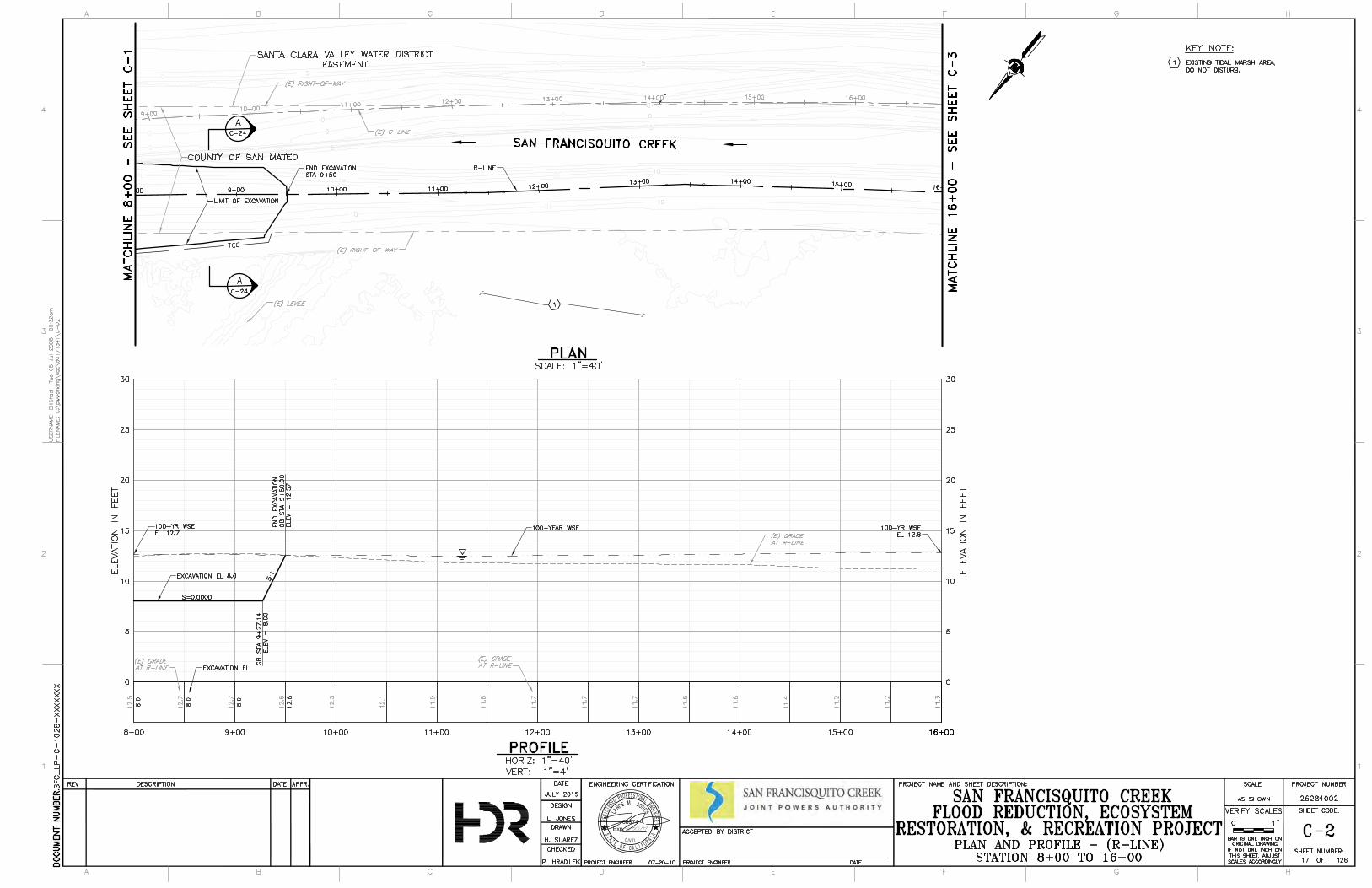
68374
Exp.