ten years of experience with a small jet engine as a ... · pdf fileten years of experience...
TRANSCRIPT

1
taAbAaim
dptaos
umscss
aRat
t1R2
J
Downloa
O. LéonardProfessor
e-mail: [email protected]
J. P. ThomasFNRS Research Fellow
e-mail: [email protected]
S. BorguetResearch Engineer
e-mail: [email protected]
Turbomachinery Group,University of Liège,
Chemin des Chevreuils, 1B-4000 Liège, Belgium
Ten Years of Experience With aSmall Jet Engine as a Support forEducationIn 1997 the Turbomachinery Group of the University of Liège decided to acquire a smalljet engine to illustrate the courses in propulsion and to provide the students with theopportunity to get some experience on data measurement, acquisition, and interpretation.Among others, the SR-30 engine from Turbine Technology Ltd. Chetek, WI was chosen. Itconsists of a single spool, single flow engine with a centrifugal compressor, a reversedcombustion chamber, an axial turbine, and a fixed convergent nozzle. This engine wasinstalled on a test bench allowing for manual control and providing fuel and oil to theengine. The original setup included measurements of intercomponent pressure and tem-peratures, exhaust gas temperature, and rotational speed. Since then both the engine andthe test bench have been deeply modified. These modifications were led by a tripleobjective: the improvement and the enrichment of the measurement chain, the widening ofthe engine’s operational domain, and, last but not the least, the wish to offer appealinghands-on projects to the students. All these modifications were performed at the Univer-sity of Liège and were conducted by the students as part of their Master theses. Severalperformance models of the engine were developed to support data validation and enginecondition diagnostic. This paper summarizes the developments conducted with and by thestudents, and presents the experience that was gained by using this engine as a supportfor education. �DOI: 10.1115/1.2967487�
Keywords: jet engine, test bench, hands-on projects, Master students
IntroductionThe Department of Aerospace and Mechanical Engineering of
he University of Liège, Belgium offers undergraduate and gradu-te programs leading to Bachelor, Master, and Ph.D. degrees inerospace, Mechanical, and Energetics Engineering. Air-reathing propulsion is one of the key issues of the Master inerospace engineering, whose objective is to train the students in
dvanced techniques of modeling, simulation, and measurementsn the disciplines involved in aerospace: fluid mechanics, flight
echanics, solid mechanics, propulsion, and materials.In 1997 the Turbomachinery Group of the University of Liège
ecided to acquire a small jet engine to illustrate the lessons inropulsion. The nature of the funding clearly oriented the projectoward didactic activities more than research ones, although bothre often coupled. The idea was to provide the students with thepportunity to get some experience on data measurement, acqui-ition, and interpretation.
The engine had to be not too big so that it can be operated in aniversity laboratory environment, without too drastic securityeasures, and not too small so that it offers enough didactic pos-
ibilities. Indeed there are quite a few jet engines for model air-rafts that are offered now at a reasonable price, but they are somall that it is unlikely that they can be equipped with a fewensors for intercomponent pressure and temperatures.
The SR-30 engine from Turbine Technology Ltd. was chosenmong others. This was also the choice of other teams, such asefs. �1–3�. The SR-30 is a single spool, single flow engine withcentrifugal compressor, a reversed combustion chamber, an axial
urbine, and a fixed convergent nozzle �Fig. 1�. This engine is
Contributed by the International Gas Turbine Institute of ASME for publication inhe JOURNAL OF ENGINEERING FOR GAS TURBINES AND POWER. Manuscript received April, 2008; final manuscript received April 8, 2008; published online October 10, 2008.eview conducted by Dilip R. Ballal. Paper presented at the ASME Turbo Expo
008: Land, Sea and Air �GT2008�, Berlin, Germany, June 9–13, 2008.ournal of Engineering for Gas Turbines and PowerCopyright © 20
ded 14 Oct 2008 to 139.165.121.81. Redistribution subject to ASM
installed on a test bench, which allows manual engine control andprovides fuel, oil, and pressurized air for the starting procedure�Fig. 2�.
Since 1997 both the engine and the test bench have been deeplymodified. These modifications were led by a triple objective: theimprovement and the enrichment of the measurement chain, thewidening of the engine’s operational domain, and, last but not theleast, the wish to offer appealing hands-on projects to the students.The fittings and connections of the engine to the bench were com-pletely changed and a load cell was added to measure the thrust. Avariable area nozzle was mounted on the engine so as to modifythe engine working line. Variable geometry inlet guide vanes wereadded ahead of the compressor wheel to modify the compressorcharacteristic. A servomotor was added to remotely operate thefuel valve and to control the engine using the acquisition system.Besides additional sensors were added such as a fuel flowmeterand an air flowmeter.
All these modifications were performed at the University ofLiège and were conducted by the students as part of their Mastertheses. Several thermodynamical performance models of the en-gine were also developed to support data validation, new compo-nent design �inlet guide vane and nozzle�, engine condition diag-nostic, and engine control. This paper summarizes thedevelopments conducted with and by the students, and presentsthe experience that was gained by using this engine as a supportfor education.
2 The Original EngineThe SR-30 engine from Turbine Technology Ltd. is 170 mm
�270 mm. It is a single spool, single flow engine with a centrifu-gal compressor, a reversed combustion chamber, an axial turbine,and a fixed convergent nozzle. This engine has the ability to runon different fuels, such as diesel, but using kerosene makes it
easier to start. The design operating point is defined asJANUARY 2009, Vol. 131 / 012303-109 by ASME
E license or copyright; see http://www.asme.org/terms/Terms_Use.cfm

etprlas�S
3
vbAtvobtmeaa
0
Downloa
Thrust: 140 N Fuel flow: 0.005 kg/sEGT: 720°C Airflow: 0.5 kg/sSpeed: 86,000 rpm Compression ratio: 3.4
The engine is installed on a test bench, which allows manualngine control and provides fuel, oil, and pressurized air. In 1997he original setup included measurements of some intercomponentressure and temperatures, exhaust gas temperature �EGT�, andotational speed. The thrust was not directly measured but corre-ated with the pressure in the combustion chamber. Neither theirflow nor the fuel flow was available at that time. Since thenignificant modifications have been brought by the manufacturer4�. The data acquisition is obtained with a National InstrumentsCXI chassis and displayed with LABVIEW.
Hardware ModificationsDuring initial testing of the SR-30, it was found that some
ariables were mandatory in order to perform a complete energyalance on the jet engine: the thrust, the airflow, and the fuel flow.lso, it came out that it would be interesting to control the posi-
ion of the engine equilibrium line. It was decided to build aariable area nozzle and to mount it downstream of the existingne, as a prolongation of the latter. Later it was also decided touild a variable geometry inlet guide vane to be mounted betweenhe bell-mouth inlet and the compressor wheel, so as to be able to
odify the compressor characteristic. Finally it was decided toxplore the possibility of controlling the engine using the datacquisition system and a servomotor was added to remotely oper-te the fuel valve.
Fig. 1 Cutaway of the SR-30 engine
Fig. 2 SR-30 engine on its test bench
12303-2 / Vol. 131, JANUARY 2009
ded 14 Oct 2008 to 139.165.121.81. Redistribution subject to ASM
These hardware modifications were all performed by studentsas part of their Master theses. They represent approximately 20person-months of student work.
3.1 The Thrust Measurement. In its original configurationthe jet engine was supported on two rigid “legs” and the thrustwas actually a result of a correlation with the pressure in thecombustion chamber.
To provide for free engine response to thrust, the support legswere removed and the engine was fixed on a rigid plate made ofaluminum. This plate has also to support the �heavy� system usedto actuate the variable area nozzle. The plate is free to react to theengine thrust as it hangs from the frame using four straps madefrom steel cables �Fig. 3�. In order to improve the thrust responseeven further, all of the rigid tubing connections were replacedwith flexible couplings �fuel and oil in and out, pressurized air in,and pressure and temperature measurements�.
The load transducer is a commercially available standard loadcell rated to 200 N �Sensy 2712�. The sensitivity of this load cellis 1.85 mV/V. The load cell is mounted with two kneecaps tocompensate for alignment errors. The jet engine is restrained axi-ally by the load cell �Fig. 4�. In order to calibrate the thrust mea-surement, a cable-pulley system was devised so that calibratedweights could be hung from the centerline of the jet engine. Thesystem calibrated to a resolution of 0.2 N. The thrust measurementsystem also maintains zero and is repeatable.
3.2 The Airflow Measurement. The bell-mouth originalnozzle �visible in Figs. 1 and 2� has been replaced with a cali-brated nozzle �Fig. 5�. The airflow is deduced from the differencebetween the ambient pressure and the static pressure measured by
Fig. 3 Hanging plate supporting the engine and strappingsystem
four holes at the throat of the flowmeter. The accuracy is 5 g/s.
Transactions of the ASME
E license or copyright; see http://www.asme.org/terms/Terms_Use.cfm

Fig. 4 Thrust measuring load cell
Fig. 5 Air flowmeter and variable geometry inlet guide vane
Fig. 6 The SR-30 and th
Journal of Engineering for Gas Turbines and Power
Downloaded 14 Oct 2008 to 139.165.121.81. Redistribution subject to ASM
3.3 The Fuel Flow Measurement. The fuel flow is measuredusing a volumetric sensor similar to those used for diesel engines.The sensor consists of a cavity with a known reference volumethat fills and empties according to the fuel flow sent to the injec-tors and to the fuel flow returning to the tank. A pulse is sent to anelectronic device each time the cavity is filled up. The fuel flow issimply obtained by multiplying the frequency of this signal by thereference volume of the cavity. The accuracy is 0.5% of the fullscale value.
3.4 The Variable Area Nozzle. The original engine is oper-ated by controlling the fuel flow, which is injected into the com-bustion chamber. Varying the fuel flow allows traversing the equi-librium line of the engine from idle �around 40,000 rpm� tomaximum speed �around 85,000 rpm�. It was decided to add asecond control parameter to the engine, in order to vary the posi-tion of the equilibrium line and to allow for the exploration of thecompressor map. This has been done through the addition of avariable area convergent nozzle as a prolongation of the existingone. Figure 6 depicts a cut view of the SR-30 engine featured withthe variable area nozzle.
The inlet section of the variable area nozzle is circular and fitsthe exit section of the original one. The outlet section is rectan-gular and has the same area as the inlet section �2462 mm2�. Thetransition from the circular inlet to the rectangular outlet is pro-gressive and based on a combination of conical and plane sur-faces. Two movable flaps allow decreasing the outlet sectiondown to 20% of the initial area �which is far beyond the limits ofthe engine in terms of EGT�. Of course as the outlet section areacan only decrease compared with the original value the enginerunning line can only be shifted upward. However, a nozzle witha wider outlet section would have acted as divergent-convergentfor most of the operating conditions, with the related pressuredrop. This solution was not selected considering the relatively lowtotal pressure �around 1.3 bars� at the turbine outlet section. It isrecognized that this extra nozzle did not allow a sufficient explo-ration of the compressor characteristic since the operating pointswith the minimum loss could not be reached.
The variable area nozzle is 170 mm long and is made of Inconel625 using an electro-erosion machine. It is mounted on the engineusing the six original screws that are used to fix the rear plate tothe original nozzle liner. The rotation of the two flaps is performed
e variable area nozzle
JANUARY 2009, Vol. 131 / 012303-3
E license or copyright; see http://www.asme.org/terms/Terms_Use.cfm
ub
swbos
cTrwwnobr
piqoc
t g
0
Downloa
sing a dc servomotor and a notched belt �visible in Fig. 8�. It cane either operated manually or included in a control loop.
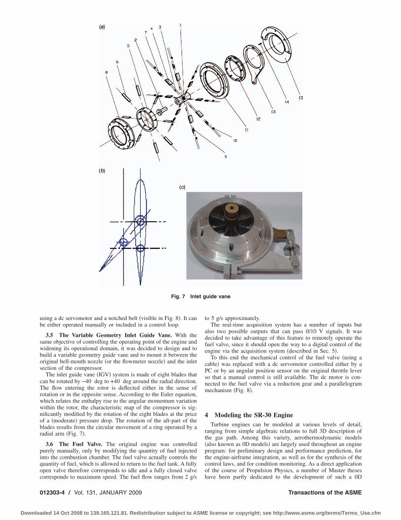
3.5 The Variable Geometry Inlet Guide Vane. With theame objective of controlling the operating point of the engine andidening its operational domain, it was decided to design and touild a variable geometry guide vane and to mount it between theriginal bell-mouth nozzle �or the flowmeter nozzle� and the inletection of the compressor.
The inlet guide vane �IGV� system is made of eight blades thatan be rotated by −40 deg to +40 deg around the radial direction.he flow entering the rotor is deflected either in the sense of
otation or in the opposite sense. According to the Euler equation,hich relates the enthalpy rise to the angular momentum variationithin the rotor, the characteristic map of the compressor is sig-ificantly modified by the rotation of the eight blades at the pricef a �moderate� pressure drop. The rotation of the aft-part of thelades results from the circular movement of a ring operated by aadial arm �Fig. 7�.
3.6 The Fuel Valve. The original engine was controlledurely manually, only by modifying the quantity of fuel injectednto the combustion chamber. The fuel valve actually controls theuantity of fuel, which is allowed to return to the fuel tank. A fullypen valve therefore corresponds to idle and a fully closed valve
Fig. 7 Inle
orresponds to maximum speed. The fuel flow ranges from 2 g/s
12303-4 / Vol. 131, JANUARY 2009
ded 14 Oct 2008 to 139.165.121.81. Redistribution subject to ASM
to 5 g/s approximately.The real-time acquisition system has a number of inputs but
also two possible outputs that can pass 0/10 V signals. It wasdecided to take advantage of this feature to remotely operate thefuel valve, since it should open the way to a digital control of theengine via the acquisition system �described in Sec. 5�.
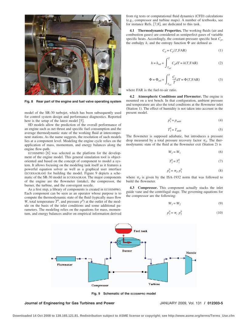
To this end the mechanical control of the fuel valve �using acable� was replaced with a dc servomotor controlled either by aPC or by an angular position sensor on the original throttle leverso that a manual control is still available. The dc motor is con-nected to the fuel valve via a reduction gear and a parallelogrammechanism �Fig. 8�.
4 Modeling the SR-30 EngineTurbine engines can be modeled at various levels of detail,
ranging from simple algebraic relations to full 3D description ofthe gas path. Among this variety, aerothermodynamic models�also known as 0D models� are largely used throughout an engineprogram: for preliminary design and performance prediction, forthe engine-airframe integration, as well as for the synthesis of thecontrol laws, and for condition monitoring. As a direct applicationof the course of Propulsion Physics, a number of Master theses
uide vane
have been partly dedicated to the development of such a 0D
Transactions of the ASME
E license or copyright; see http://www.asme.org/terms/Terms_Use.cfm
mfh
aanlae
motp�mob
EcWurt
F
J
Downloa
odel of the SR-30 turbojet, which has been subsequently usedor control system design and performance diagnostics. Reportedere is the setup of the latest model �5�.
0D models allow the prediction of the overall performance ofn engine such as net thrust and specific fuel consumption and theverage thermodynamic state of the working fluid at intercompo-ent stations. As the name suggests, the resolution of such modelsies at a component level. Modeling the engine cycle relies on thepplication of mass, momentum, and energy balances along thengine flow-path.
ECOSIMPRO �6� was selected as the platform for the develop-ent of the engine model. This general simulation tool is object-
riented and based on the concept of component to model a sys-em. It allows focusing on the modeling task itself as it features aowerful equation solver as well as a graphical user interfaceECODIAGRAM� for building the model. Figure 9 depicts a sche-atic of the SR-30 model in ECODIAGRAM. The major components
f the engine are the flowmeter �intake�, the compressor, theurner, the turbine, and the convergent nozzle.
As a first step, a library of components is created in ECOSIMPRO.ach component can be seen as an operator whose purpose is toompute the thermodynamic state of the fluid �typically mass flow, total temperature T0, and pressure p0� at the outlet of the mod-
le on the basis of the inlet conditions and some additional pa-ameters. The modeling relies on the equations for mass, momen-um, and energy balances and/or on empirical information derived
ig. 8 Rear part of the engine and fuel valve operating system
Fig. 9 Schematic of th
ournal of Engineering for Gas Turbines and Power
ded 14 Oct 2008 to 139.165.121.81. Redistribution subject to ASM
from rig tests or computational fluid dynamics �CFD� calculations�e.g., compressor and turbine maps�. A number of textbooks, seefor instance Refs. �7,8�, are dedicated to this task.
4.1 Thermodynamic Properties. The working fluids �air andcombustion gases� are considered as semiperfect gases of variablespecific heats. Accordingly, the constant-pressure specific heat Cp,the enthalpy h, and the entropy function � are defined as
Cp = Cp�T,FAR� �1�
h = href +�Tref
T
CpdT = h�T,FAR� �2�
� = �ref +�Tref
TCp
TdT = ��T,FAR� �3�
where FAR is the fuel-to-air ratio.
4.2 Atmospheric Conditions and Flowmeter. The engine ismounted on a test bench. In that configuration, ambient pressureand temperature are also the total conditions at the flowmeter inlet�Station 1�. The effect of humidity is not taken into account in thepresent model.
p10 = pamb �4�
T10 = Tamb �5�
The flowmeter is supposed adiabatic, but introduces a pressuredrop measured by a total pressure recovery factor �d. The ther-modynamic state of the fluid at the flowmeter exit �Station 2� is
W2 = W1 �6�
T20 = T1
0 �7�
p20 = �d p1
0 �8�
where �d is given by the ISA-1932 norm that was followed tobuild the flowmeter.
4.3 Compressor. This component actually stacks the inletguide vane and the centrifugal stage. The governing equations forthe compressor are the following:
W3 = W2 �9�
p30 = �c p2
0 �10�
e ECOSIMPRO model
JANUARY 2009, Vol. 131 / 012303-5
E license or copyright; see http://www.asme.org/terms/Terms_Use.cfm

Tf
Tftetos
waa
oe
w
ba
Ta
ws
q
Tf
Dcas
0
Downloa
h30 = h2
0 +1
�c�h3,is
0 − h20� �11�
he isentropic outlet enthalpy h3,is0 is computed from the entropy
unction
�3,is = �2 + R log��c� �12�
he characteristic curves of the compressor have been worked outrom a mean-line analysis �9� and are stored in the �-lines formato prevent numerical interpolation problems. Accounting for theffect of the inlet guide vane, the corrected inlet mass flow W2
std,he pressure ratio �c, and the isentropic efficiency �c are functionsf the corrected spool speed N2
std, the �-coordinate, and the IGVtagger angle �IGV as follows:
W2std = CWstd fWstd�N2
std,�,�IGV� �13�
�c = C� f��N2std,�,�IGV� �14�
�c = C� f��N2std,�,�IGV� �15�
here CWstd, C�, and C� are so-called map scaling factors that arepplied to the performances read in the map so that they match thectual compressor performances.
The power required to drive the compressor is given by
PWc = W3�h30 − h2
0� �16�
4.4 Burner. The combustion chamber increases the enthalpyf the working fluid through the burning of fuel. The governingquations for this component are
W4 = W3 + WF �17�
p40 = �b p3
0 �18�
h40 =
�bWFLHV + W3h30
W4�19�
here LHV stands for low heating value of the fuel.The combustion efficiency �b expresses the fact that the com-
ustion process is incomplete. It is very well correlated with their loading AL as follows:
AL =W3
vol�p30�1.8100.00145�T3
0−400��20�
he pressure recovery factor �b accounts for the friction lossesnd is evaluated according to
�b = 1 − Kb�W3�T3
0
p30 �2
�21�
here Kb is a constant depending on the burner geometry andurface roughness.
4.5 Turbine. The constitutive equations for the turbine areuite similar to those of the compressor as follows:
W5 = W4 �22�
p50 = �t p4
0 �23�
h50 = h4
0 + �t�h5,is0 − h4
0� �24�
he isentropic outlet enthalpy h5,is0 is computed from the entropy
unction
�5,is = �4 + R log��t� �25�
ue to the moderate compressor pressure ratio, the turbine is un-hoked for most of the operating regimes. Moreover, no map isvailable, be it from the manufacturer or from a mean-line analy-
is. As a workaround, Stodola’s ellipsis is used for describing the12303-6 / Vol. 131, JANUARY 2009
ded 14 Oct 2008 to 139.165.121.81. Redistribution subject to ASM
pressure ratio �t-corrected mass flow W4std relation
W4std = Kt
�1 − �tnt �26�
where Kt and nt are constant parameters that characterize the tur-bine stage. Stodola’s model treats the turbine as a nozzle, as far asthe �W4
std ,�t� curve is concerned, and therefore neglects the influ-ence of the rotational speed on the stage characteristic.
Considering the isentropic efficiency �t, a correlation with theinlet corrected mass flow is to be determined from the experimen-tal measurements.
The available power generated by the turbine is given by
PWt = �mW4�h40 − h5
0� �27�
The mechanical efficiency �m accounts for the loss generated inthe bearings supporting the shaft.
4.6 Exhaust Nozzle. Assuming an adiabatic process, the con-stitutive equations write down
W9 = W5 �28�
p90 = �np5
0 �29�
T90 = T5
0 �30�
where �n represents the pressure loss across the nozzle and ismodeled as the burner pressure loss �21�.
The nozzle expansion ratio NER= pamb / p90 is subcritical for the
whole operating range, which means that the static pressure in theexit plane p9 is equal to the ambient pressure pamb and the exhaustMach number is subsonic. From the exit Mach number M9 andtotal temperature T9
0, the exhaust jet velocity V9 can be computedwith usual equations. A discharge coefficient CD is introduced toaccount for the reduction of effective flow area due to the bound-ary layer. CD is correlated with the NER as follows:
CD =A9,eff
A9,geom= CD�NER� �31�
Finally, the thrust generated by the engine is assessed with a mo-mentum balance between the engine inlet and outlet as follows:
FG = W9V9 + A9,eff�p9 − pamb� �32�
The net thrust confounds with the gross thrust since the engine isnot moving and the pressure term vanishes as the nozzle isunchoked.
4.7 Assembling the Components. To build the engine model,the basic modules presented in Secs. 4.1 through 4.6 are as-sembled following the general schematic of Fig. 9. Ensuring theconservation of mass, momentum, and energy throughout the en-gine generates constraints, which actually restrict the operatingrange of each component. The conservation principles translateinto a set of nonlinear algebraic equations, also termed compat-ibility equations that are solved with ECOSIMPRO’s built-inalgorithms.
From an external point of view, the engine model can be seen asa vector-valued function
y = G�u� �33�
where u is the vector of command parameters that define the op-erating point of the engine �fuel flow, nozzle area, IGV angle,ambient temperature, and pressure� and y is the vector of mea-surements �total temperature and pressure at various stations,spool speed, and thrust�.
4.8 Fitting the Engine Model to Test Data. Numerous pa-rameters have appeared in the modeling of the components. Theirvalues must be determined on the basis of experimental data col-lected on the engine so that the resulting model is representative
of the actual engine behavior. This task is usually known as modelTransactions of the ASME
E license or copyright; see http://www.asme.org/terms/Terms_Use.cfm

fiewn
tmsttsi
fit
Tmottada
J
Downloa
tting/tuning. Data have been collected on the engine in the op-rating range 55,000–75,000 rpm per steps of 2500 rpm. The testsere conducted at a nominal IGV stagger and a fully openedozzle.
Model fitting has been carried out in two stages. Raw estima-ions of the various parameters and correlations have been deter-
ined from a first tuning procedure applied to each componenteparately. As some important quantities are not available �e.g.,urbine inlet total pressure p4
0� or are at best rough indicators �e.g.,urbine inlet total temperature T4
0�, the values of some parametersuch as mechanical efficiency or burner pressure loss have beenmposed to common values.
Second, a fine tuning of the model has been performed. Thetting parameters are now computed at a global level. To this end,
hey are considered as additional inputs w of the model:
y = G�u,w� �34�
he tuning task can be seen as the inverse problem of perfor-ance prediction. Knowing the command parameters u and the
bserved measurements y, the parameters w are modified so thathe residuals between the experimental data and the model predic-ions are minimized in the least-squares sense. The minimizationlgorithm implements a Kalman filter �see Ref. �10� for details�eveloped in the Turbomachinery Group in the frame of researchctivities in health monitoring. Figure 10 sketches the general
Fig. 10 Tuning procedure using an extended Kalman filter
Fig. 11 Fuel flow—EGT curve
ournal of Engineering for Gas Turbines and Power
ded 14 Oct 2008 to 139.165.121.81. Redistribution subject to ASM
principle of the recursive tuning of model parameters.Some results of the fitting procedure are sketched in Figs. 11
and 12. The blue dots are the experimental data, the dotted bluelines are the uncertainty bounds on the measurements, the red lineis the model prediction after the first tuning step, and the greenline is the model prediction after refining the parameter valueswith the Kalman filter.
Figure 11 depicts the evolution of the exhaust gas temperatureT9
0 with respect to the fuel flow. It can be seen that the modelpredictions are already within the uncertainty bounds for thehigher operating regimes after the first tuning process. The secondpass with the Kalman filter improves the results in the mid- andlow-power regions.
Figure 12 represents the evolution of the airflow W2 with re-spect to the fuel flow. For this particular quantity, the first tuningprocedure is clearly unsuccessful as the prediction of airflow isoutside the confidence limits for the whole operating line. Thefurther fitting performed by the Kalman filter dramatically im-proves the quality of the mass flow prediction for the regimesconsidered. Conclusions similar to those drawn for Figs. 11 and12 are valid for the other measurements.
Fig. 12 Fuel flow—airflow curve
Fig. 13 Trajectory of the operating point for a deceleration fol-lowed by an acceleration in the compressor map: steady-line„red curve…, limits on the mass flow „black curves…, and steady
operating points „black circles…JANUARY 2009, Vol. 131 / 012303-7
E license or copyright; see http://www.asme.org/terms/Terms_Use.cfm
5
asttt
WwEaqdot
tplftt�
M
matdtotlp
0
Downloa
Controlling the SR-30 EngineA transient mathematical model of the engine can be made
vailable by adding one equation to the steady-state model de-cribed above. This equation describes the evolution of the rota-ional speed with time by balancing the power developed by theurbine, the power required by the compressor, and the inertia ofhe rotating parts as follows:
J�2�
60�2
NdN
dt= PWt − PWc �35�
hereas the dynamic behavior of the rotational speed is capturedith some accuracy provided that the additional parameter J inq. �35� is correctly determined, the evolutions of the mass flownd the temperatures are more qualitatively captured. As the ac-uisition system is able to output signals and as the fuel valve isriven now by a dc motor, it was decided to explore the possibilityf controlling the fuel flow injected into the engine correspondingo prescribed objectives.
The objectives are the minimization �at least the reduction� ofhe time required for transients, while avoiding the trespass of anyhysical limit of the engine. The rotational speed has been se-ected to play the role of the performance parameter from which aeedback action is determined, as it is the case on most of gasurbine engines. The physical limits are specified in terms of ro-ational speed �minimum and maximum levels�, air and fuel flowsminimum and maximum values�, and maximum EGT.
A controller has been devised for this virtual engine usingATLAB/SIMULINK. The control device includes the following ele-ents: a feedforward action that generates a command, a feedback
ction that generates a correction of the feedforward in function ofhe error, one control action per physical limit, and an antiwindupevice. The control strategy has to pursue the following objec-ives: reduction of the response time, zero static error, no violationf any of the physical limits, robustness against external perturba-ions, and sensor noise. A proportional-integral-derivative controlaw has been selected for the rotational speed �tuned with theerformance index ITAE1�, while a proportional-integral control
1 T
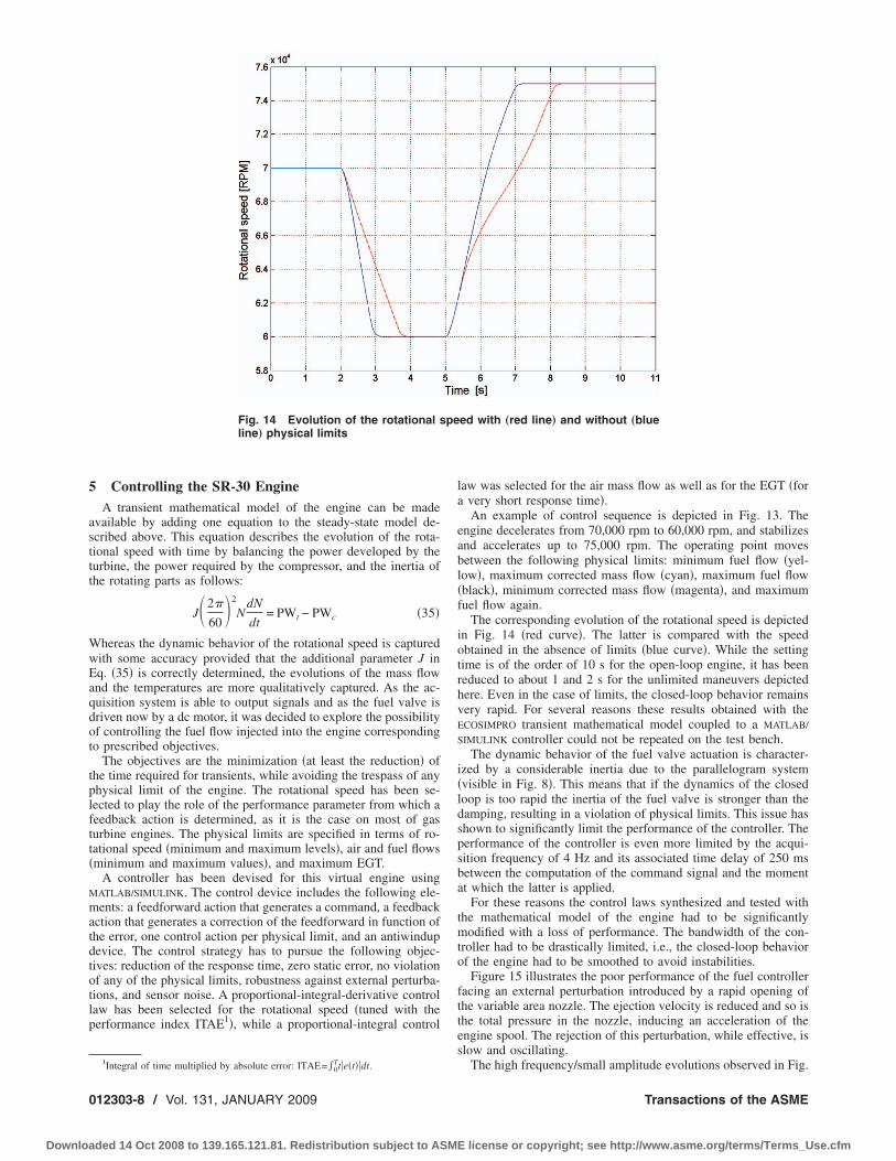
Fig. 14 Evolution of the rotational sline… physical limits
Integral of time multiplied by absolute error: ITAE=0te�t�dt.
12303-8 / Vol. 131, JANUARY 2009
ded 14 Oct 2008 to 139.165.121.81. Redistribution subject to ASM
law was selected for the air mass flow as well as for the EGT �fora very short response time�.
An example of control sequence is depicted in Fig. 13. Theengine decelerates from 70,000 rpm to 60,000 rpm, and stabilizesand accelerates up to 75,000 rpm. The operating point movesbetween the following physical limits: minimum fuel flow �yel-low�, maximum corrected mass flow �cyan�, maximum fuel flow�black�, minimum corrected mass flow �magenta�, and maximumfuel flow again.
The corresponding evolution of the rotational speed is depictedin Fig. 14 �red curve�. The latter is compared with the speedobtained in the absence of limits �blue curve�. While the settingtime is of the order of 10 s for the open-loop engine, it has beenreduced to about 1 and 2 s for the unlimited maneuvers depictedhere. Even in the case of limits, the closed-loop behavior remainsvery rapid. For several reasons these results obtained with theECOSIMPRO transient mathematical model coupled to a MATLAB/
SIMULINK controller could not be repeated on the test bench.The dynamic behavior of the fuel valve actuation is character-
ized by a considerable inertia due to the parallelogram system�visible in Fig. 8�. This means that if the dynamics of the closedloop is too rapid the inertia of the fuel valve is stronger than thedamping, resulting in a violation of physical limits. This issue hasshown to significantly limit the performance of the controller. Theperformance of the controller is even more limited by the acqui-sition frequency of 4 Hz and its associated time delay of 250 msbetween the computation of the command signal and the momentat which the latter is applied.
For these reasons the control laws synthesized and tested withthe mathematical model of the engine had to be significantlymodified with a loss of performance. The bandwidth of the con-troller had to be drastically limited, i.e., the closed-loop behaviorof the engine had to be smoothed to avoid instabilities.
Figure 15 illustrates the poor performance of the fuel controllerfacing an external perturbation introduced by a rapid opening ofthe variable area nozzle. The ejection velocity is reduced and so isthe total pressure in the nozzle, inducing an acceleration of theengine spool. The rejection of this perturbation, while effective, isslow and oscillating.
ed with „red line… and without „blue
peThe high frequency/small amplitude evolutions observed in Fig.
Transactions of the ASME
E license or copyright; see http://www.asme.org/terms/Terms_Use.cfm

1tdppitl
vect
seTh
6
w
J
Downloa
5 �and further in Fig. 16� are probably the consequence of addi-ional poor features of the fuel valve actuator. The latter intro-uces strong nonlinearities due to internal friction forces, inducingarasitic movements of the fuel valve and degrading the transienterformance of the whole system. The command noise character-zing the original fuel valve actuation is another issue. It is due tohe necessary clearance in the kneecap mechanisms of the paral-elogram system.
Figure 16 illustrates the result of the follow-up of an assignedalue for the rotational speed equal to 70,000 rpm. The maximumrror is about 100 rpm, but the mean error is below 50 rpm, whichan be considered as rather successful considering the above men-ioned shortcomings of the actuation system.
The replacement of the original fuel valve and its actuationystem with a proportional electrical valve whose dynamics is fastnough seems to be the only way to overcome these problems.his solution has been implemented by Watanabe et al. �1� andas been undertaken this year in our group by a Master student.
ConclusionsThe main characteristic of gas turbines, i.e., power density, is
Fig. 15 Rejection of an external perturbation
Fig. 16 Follow-up of a prescribed rotational speed
ell illustrated by the SR-30 engine, which is a reliable and ef-
ournal of Engineering for Gas Turbines and Power
ded 14 Oct 2008 to 139.165.121.81. Redistribution subject to ASM
fective demonstrator of many aspects of gas turbine operation. Asnoted by other academic teams, the single-point one-dimensionalinstrumentation typical of this small scale engine makes it some-what difficult to obtain accurate results. However, the SR-30 is anexcellent opportunity for the students to learn about the limita-tions of simplifying assumptions and about the difficulty associ-ated with data acquisition, treatment, and interpretation.
The development of a computer model of the engine has shownthat, by coupling principles of thermodynamics and mechanics tomeasured data and to a smart parameter identification procedure,it is possible to obtain meaningful results, despite the lack ofinformation about component performance �no compressor norturbine maps are available�. These results would not have beenobtained without the additional instrumentation, i.e., airflow, fuelflow, or thrust measuring devices.
The modifications of the test bench to implement these addi-tional sensors, the design, the development, and the implementa-tion of additional components for the engine itself, such as an inletguide vane or a variable area nozzle, as well as the tentative tocontrol the engine via the acquisition system, represented veryappealing projects for the students. These projects were also quitesuccessful in terms of educational objectives because they implieda deep understanding of the physics of many phenomena.
AcknowledgmentThis work has been performed by the following Master stu-
dents: Pierre-Yves Hanquet �thrust measurement�, Anthony Mi-gnon �variable area nozzle�, Pierre Seronveaux �actuation via dcmotors�, Benoît Vertessen �design of the inlet guide vane�, ClaudeMockels �integration of the inlet guide vane�, Jean-Philippe Tho-mas �new thrust measurement frame and control of the engine�,Khanh Mai Quoc �identification of the engine model�, andFrançois Denis �proportional electrical fuel valve�. The success ofthe SR-30 in our laboratory is also due to the strong support of itsmanufacturer, despite the distance.
NomenclatureA � area
FG � thrusth ,h0 � enthalpy, total enthalpy
J � spool inertiaN � spool speed
p , p0 � pressure, total pressurePW � power
R � gas constantT ,T0 � temperature, total temperature
W ,WF � air mass flow, fuel mass flow� � isentropic efficiency� � entropy function� � pressure ratio
Subscripts and Superscripts1 � intake inlet
2,3 � compressor inlet, compressor outlet4,5 � turbine inlet, turbine outlet
9 � exhaustb � burnerc � compressort � turbine
amb � ambientis � isentropic
std � corrected for standard conditions
References�1� Watanabe, A., lmen, S. M., Leland, R., Whitaker, K. W., and Trevino, L. C.,
2004, “Soft Computing Applications on SR-30 Turbojet Engine,” AIAA PaperNo. 2004–6444.
�2� Perez-Blanco, H., 2003, “Activities Around the SR-30 Minilab at PSU,” Pro-
ceedings of the 2003 American Society for Engineering Education AnnualJANUARY 2009, Vol. 131 / 012303-9
E license or copyright; see http://www.asme.org/terms/Terms_Use.cfm

0
Downloa
Conference and Exposition, The American Society for Engineering Education,Nashville, TN.
�3� Witkowski, T., White, S., Ortiz Dueas, C., Strykowski, P., and Simon, T., 2003,“Characterizing the Performance of the SR-30 Turbojet Engine,” Proceedingsof the 2003 American Society for Engineering Education Annual Conferenceand Exposition, The American Society for Engineering Education, Nashville,TN.
�4� Turbine Technologies Ltd, http://www.turbinetechnologies.com�5� Mai, Q.-K., 2006, “Simulation of the Performance of the SR-30 Turbojet �in
French�,” M.S. thesis, University of Liège, Liège, Belgium.
12303-10 / Vol. 131, JANUARY 2009
ded 14 Oct 2008 to 139.165.121.81. Redistribution subject to ASM
�6� EcosimPro by EA Internacional, http://www.ecosimpro.com�7� Mattingly, J. D., 1996, Elements of Gas Turbine Propulsion, McGraw-Hill,
Singapore.�8� Walsh, P. P., and Fletcher, P., 1998, Gas Turbine Performance, Blackwell
Science, Oxford.�9� Vertessen, B., 2001, “Design of a Variable Guide Vane for the SR-30 Turbojet
�in French�,” M.S. thesis, University of Liège, Liège, Belgium.�10� Dewallef, P., 2005, “Application of the Kalman Filter to Health Monitoring of
Gas Turbine Engines: A Sequential Approach to Robust Diagnosis,” Ph.D.thesis, University of Liège, Liège, Belgium.
Transactions of the ASME
E license or copyright; see http://www.asme.org/terms/Terms_Use.cfm