tender - bmtpc · building materials & technology promotion council ... the agency who have...
TRANSCRIPT

TENDER
FOR
Construction of 36 Demonstration Houses (G+2) on Design & Build basis with any of the following technologies Including on site Infrastructure Work at Sohan Kuan, Mauza Chakhaijyain, Biharsharif, Bihar
1. Stay in place EPS based double walled panel system with infill
concrete. 2.Monolithic construction with structural stay in place CR steel
specially designed formwork system 3.Light Gauge Steel Framed Structure with suitable cladding
and insulation system
Composite Work
(Ref. No. BMT/CBM/1/2016/BIHAR)
BUILDING MATERIALS & TECHNOLOGY PROMOTION COUNCIL Ministry of Housing & Urban Poverty Alleviation, Govt. of India
Core-5A, First Floor, India Habitat Centre Lodhi Road, New Delhi-110003
Phone: +91-11-24636705; Fax: +91-11-24642849; E-mail: [email protected]; Website: www.bmtpc.org

TENDER NOTICE BMTPC invites sealed offers in two bid system from reputed, experienced, technically and financially sound Technology providers, companies, firms, contractors/ developers, Joint Venture (hereafter called Agency), public & private agencies for construction of 36 Demonstration Houses (G+2) using emerging technologies including infrastructure works at Sohankuan, Mauza Chakhajiyain, Bihar Shariff, Bihar on Design & Build basis. Interested parties may submit their bids
within 21 days from the date of advertisement in the newspapers at the following address in the manner as described in the detailed Tender Document available on BMTPC’s website www.bmtpc.org.
Any further changes/relevant information would be intimated only through the website of the Council. Building Materials & Technology Promotion Council, (Ministry of Housing & Urban Poverty Alleviation,
Govt. of India), Core-5A, 1st Floor, India Habitat Centre, Lodhi Road, New Delhi-110003, Tel:011-24638096/97.
Chief (Admn)
Construction of 36 Demonstration Houses (G+2) on Design & Build basis with any of the following technologies Including on site Infrastructure Work at Sohan Kuan, Mauza Chakhaijyain, Bihar Sharif, Bihar
1. Stay in place EPS based double walled panel system with infill
concrete. 2. Monolithic construction with structural stay in place CR steel
specially designed formwork system 3. Light Gauge Steel Framed Structure with suitable cladding
and insulation system
Composite Work (Ref. No. BMT/CBM/1/2016/BIHAR)
Part-A
TECHNICAL BID

INDEX
Name of Work : Construction of 36 Demonstration Houses (G+2) on Design & Build basis with any of the following technologies Including on site Infrastructure Work at Sohan Kuan, Mauza Chakhaijyain, Bihar Sharif, Bihar
1. Stay in place EPS based double walled panel system with In fill
concrete. 2. Monolithic construction with structural stay in place CR steel specially
design formwork system 3. Light Gauge Steel Framed Structure with suitable cladding and
insulation system PART-A (TECHNICAL BID)
S. No.
Description PAGE NO.
1. TENDER NOTICE 2 - 6
2. DESIGN DATA & SPECIFICATIONS FOR THE PROJECT 7-16
3. GENERAL CONDITIONS & INSTRUCTION TO THE BIDDER 17-21
4. TECHNICAL BID PROFORMAS/DETAILS 22-29
5. ADDITIONAL CONDITION & SPECIFICATION 30-33
6. SALIENT FEATURES/ INTERPRETATION OF VARIOUS CLAUSES OF THE GENERAL CONDITION OF CONTRACT OF CPWD
34-35
7. ORGANIZATION CHART 36
8. LIST OF PREFERED MAKES FOR CIVIL / SANITARY/ ELECTRICAL WORKS
37-38
9. PROFORMA FOR AGREEMENT 39-42
10. INTGERITY PACT 43-49
11. FINANCIAL BID 50-61
12. ANNEXURE – 1
1a. Stay in place EPS based double walled panel system with In fill concrete.
62 – 79
1b. Monolithic construction with structural stay in place CR steel specially design formwork system.
80 – 89
1c. Light Gauge Steel Framed Structure with suitable cladding and insulation system
90 – 122
13. GEOTECHNICAL INVESTIGATION REPORT FOR PROPOSED SITE
123 – 134
14. PROPOSED DRAWINGS D1 – D19

2
fuekZ.k lkexzh ,oa izkS|ksfxdh lao)Zu ifj”kn
vkokl vkSj ‘kgjh xjhch mi’keu ea=ky;] Hkkjr ljdkj
Building Materials & Technology Promotion Council Ministry of Housing & Urban Poverty alleviation, Government of India
Core-5A, 1st Floor, India Habitat Centre, Lodhi Road, New Delhi Phone: +91-11-24636705, Fax: +91-11-24642849
Website:www.bmtpc.org Email:[email protected]
TENDER NOTICE
1. Sealed tenders are invited under Two-Bid System from reputed, experienced,
technically and financially sound Technology provider, companies, firms, contractors/ developers, Joint Venture (hereafter called Agency) public and private agencies for construction of 36 Demonstration Houses on design and build basis with any of the following Technologies: a. Stay in place EPS based double walls panel system with Infill concrete. b. Monolithic construction with strugctural stay in place steel formwork System c. Light Gauge Framed Steel Structure with suitable cladding and insulation
system Including on site infrastructure works at Sohankuan, Mauza Chakhaijyain, Biharsharif, Bihar on Design & Build basis
i) Estimated Cost: Rs 292.16 lakhs (Rupees: two hundred ninety two point one six lakhs)
ii) Time allowed: Six Months to be reckoned after fifteen days of the date
of written orders to commence the work or from the first day of handing over the site whichever is later.
iii) The site for the work has been allotted by Nagar Nigam, Bihar Sharif,
and located at Sohankuan, Chakhajiyain, Bihar Sharif, Bihar.
iv) Condition of the work: The nature of the work is on Design & Build basis. The vetting of structural Design by Technical Research Institutes of repute will be submitted by the bidder within twenty five days of the award of work.
v) EMD: Rs 584320/- (2% of Estimated Cost) vi) Cost of Tender Rs 1000/- (Non refundable) vii) Last date of submission of tender is 18-08-2016 at 3:00 PM viii) Pre Bid Meeting will be held on 09-08-2016 at 3:00 PM ix) Opening of Technical Bids will be on 18-08-2016 at 5:00 PM x) Opening of Financial Bids will be on 22-08-2016 at 3:00 PM

3
Tenders can be received from BMTPC Office by making payment of Rs. 1000/- & can also be down-loaded through the BMTPC website: www.bmtpc.org. In case of down loading, the Agency shall have to pay the cost of Tender Form Rs 1000/- in the form of DD favoring BMTPC, New Delhi at the time of submission of tender. The tender is to be submitted on the prescribed format in Two Bids in separate cover in the following manner: Part A - Bid containing requisite documents, Technical Specification, Cost of
tender, Earnest Money Deposit and Integrity pact. Part B - Bid containing Financial Offer
The Envelope containing Technical Bid and Financial Offer should be marked as Technical Bid and Financial Bid separately and submitted in another envelope duly sealed and super scribed “Tender for Construction of Demonstration Houses including on site Infrastructure work at Sohankuan Chakhajiyain, Bihar Sharif, Bihar”. The EMD, Cost of Tender & all requisite documents must be attached with the Technical Bid. The Financial Bid shall contain the rates only. NOTE: The Agencies are invited to be present in pre-bid meeting for clarifications if any. The suggestions by the agencies limited to issues found incompatible with technology in the tender document may only be accepted for consideration in pre-bid meeting. If some modifications are affected in pre-bid meeting, the same would be uploaded on BMTPC web site. These bids will be opened in two stages. The bid containing requisite documents technical Specification and Earnest Money deposit will be opened at the 1st stage on and if the same is found to be acceptable by BMTPC the bid containing financial offer shall be opened in 2nd stage. Only those Agencies would be informed whose technical bid are accepted. Incomplete & Conditional tenders shall be summarily rejected. The tender duly filled in should be sent by post or by hand so as to reach BMTPC Office on or before due date and time at the following address. Tenders received late due to postal delay or some reasons will be the responsibility of the Agency, and shall not be accepted. Agency should read the General Condition and Terms & Condition and instruction and other conditions carefully before filling the tender.

4
Address for Communication: Executive Director Building Materials & Technology Promotion Council (BMTPC) Core-5A, 1st Floor, India Habitat Centre, Lodhi Road, New Delhi - 110 003
1.1 ELIGIBILITY CRITERIA
Reputed, experienced, technically and financially sound Technology provider, companies, firms, contractors/ developers, Joint Venture for construction of houses/buildings (hereafter called Agency) public and private agency who will be able to meet the following eligibility criteria, shall be eligible to apply.
i. Registered Agency having valid statutory VAT registration, PAN Number,
WCT No, Service Tax Number, PF, labour etc. ii. The average Annual turnover of the agency / tenderer shall not be less
than 150,000,00.00 (Rupees: One hundred fifty Lakh ) per year for the last three years.
iii. The Agency who have been debarred from undertaking any work and blacklisted by any organization/ agency as on date of submission of tender, shall be summarily rejected. An affidavit shall be submitted by the Agency that the company is not blacklisted from the Government Organization.
iv. Work Experience: The Agency should have experience of having successfully completed works using conventional technology and/or pre-fabricated technologies (Building work) during the last five years ending last day of the month previous to the one in which applications are invited:
Three similar completed works costing each not less than the
amount equal to 40% of estimated cost of work put to bid, OR
Two similar completed works, each of value not less than 60% of the estimated cost put to bid
OR One similar completed work of value not less than 80% of the
estimated cost put to bid
Similar work here shall mean building works like Residential, Office complex, Institutional, Shopping complex and like other building works using conventional and/or prefabricated technologies.

5
The value of executed works shall be brought to current costing level by enhancing the actual value of work at simple rate of 7% per annum; calculated from the date of completion to last date of receipt of applications for tenders.
v. Certification of the Technology
The structural system of the technology shall be certified by any of the followings; a) BMTPC (under its Performance Appraisal Certification Scheme) b) CBRI, Roorkee c) SERC, Chennai d) Any IIT’s e) Any NIT’s f) Any reputed National / International technical institutions.
For Agency other than Technology Provider or not as JV with technology provider must have undertaking for regular supply from single source of certified prefabricated panels conforming to the specifications as mentioned in technology details given in the Annexure I to be used in the project. This Undertaking if applicable shall be part of the documents to be submitted with technical bid.
vi. If any information furnished by the Agency is found incorrect at a later
stage, he shall be liable to be debarred from further bidding and taking works. The Project Authority reserves the right to verify the contents / particulars furnished by the Agency independently including inspection of work completed by them.
1.2 The tender shall be valid for 120 days from the date of it’s submission. 1.3 Only one type of JV is allowed for any Agency, which is between the
Technology provider and the Agency himself. In this case, the Agency shall submit all the documents regarding the technical & financial eligibility, whereas the technology provider shall submit all the certificates related to the construction technology and vice-versa.
1.4 In case the Agency is JV, the members of the JV shall furnish a Power of Attorney designating one of the members, as per the JV agreement, as their Lead Member. The lead member shall be fully responsible for the satisfactory performance of the JV.
1.5 A copy of the JV Agreement registered should be submitted. The JV agreement entered into the members of the JV should be specific to the project only.
1.6 List of documents to be attached with the technical Bid; i. The Demand Draft for tender fee and Earnest Money deposit of any
Nationalized Bank in original. ii. Audited balance sheet of last five financial years

6
iii. Audited certificate showing net worth of last five financial years iv. Income tax return of last 5 financial years. v. Copy the Bank Solvency certificate (not older than six months) vi. Certificate of work experience as mentioned in Eligibility Criteria vii. Performance certificate for the proposed technology as mentioned in
eligibility Criteria viii. Performance Report ix. Detailed organizational structure including technical manpower. x. Details of construction Plants, equipment etc. available with the
Agency. xi. Litigation Details xii. Certificate of registration of Company/Firm. xiii. Details of registration/empanelment with Central/State agencies/PSUs xiv. Copy of VAT registration, PAN No., WCT No, Service Tax No. xv. PF registration certificate. xvi. Valid license under Contract Labour (R&A) Act 1970. xvii. The certificate for the Structural System of the Technology. xviii. Complete details of proposed technology including specification xix. Any other relevant documents as desired by the Agency.
For and on Behalf of BMTPC

7
2. DESIGN DATA & SPECIFICATIONS FOR THE PROJECT
The layout plan & architectural drawing of the proposed building (G+2) is attached. The total built up area including staircase is 17641.00 Sqft The design data & specifications to be used are as below.
2.1 DESIGN DATA
The Agency is required to design & prepare the structural working drawings for the houses as per the Architectural drawings attached herewith. The design shall be based on the following parameters & latest version of IS Codes shall be referred to;
i) The Soil investigation has been conducted by BMTPC and the report is
placed at Annexure II.
ii) Dead load is to as per the actual load of Panel and other material used based on IS-875 Part-I & imposed load as per dwelling houses category of residential buildings as per IS 875 Part-II
iii) Wind speed as per IS : 875 Part-III
iv) Earth quake forces as per IS 1893
v) Special loads and load combinations as per IS 875 Part-V
vi) Plinth level of Building is to be + 450 mm from adjacent road level
vii) Type of structure: G+2 Structure above plinth level
2.2 Vetting of Design & drawings The design of the structure for structural and functional requirement shall be done for combined effect of applicable dead load, imposed load, earthquake forces, wind loads and other loads as per applicable Indian Standards and National Building Code of India and actual site conditions. It would be the responsibility of bidder to get the Design and Drawings of structure vetted by Technical / Research institutions of repute such as IITs, NITs, CSIR Labs, Govt. Research Institutions and/or by any reputed National/ International technical institutions as found acceptable by BMTPC.

8
2.3 Technical Specifications of various technologies are given at Annexure- I for building structure;
The technical specification would be entirely based on design parameters, however, the minimum specification as given below is recommended to be adhered to; a) Foundation: The foundation shall be designed on the basis of soil
condition of the site as per soil bearing capacity report attached at Annexure II with isolated columns and plinth beams up to plinth level. However bearing capacity may be further verified by the bidder at site. Anti termite treatment as per CPWD specification shall be provided.
b) Staircase The Agency can propose for construction of staircase in RCC or as per technology proposed for the project for approach on all floors up to terrace floor.

9
2.4 ELECTRICAL INSTALLATIONS SPECIAL CONDITIONS General
1. These Special Conditions are part of the Contract and the contractor shall go through it as he shall not have any right to claim at any time for delays or for expenditure incurred by him in fulfilling the following special conditions. Special Conditions of Contract (SCC) shall be read in conjunction with Technical Specifications, Schedule of Quantities, Tender Drawings and any other document forming part of this contract Agreement.
1.1. Electrical License The Agency shall employee licensed supervisors and skilled workers having valid permits as per the regulations of Indian Electricity Rules and local Electrical Inspectors requirements.
1.2. Conformity to IE Act, IE Rules, and BIS standards a) All Electrical works shall be carried out in accordance with
provisions of Indian electricity Act, 1910 and Indian Electricity Rules, 1956 amended up to date (Date of call of tender unless specified otherwise).
b) The definition of terms shall be in accordance with IS: 732-1989 (Indian standard Code of Practice for Electrical wiring), except for the definitions of point, circuit and sub main wiring which are defined in the General specifications for Electrical Works Part-1 Internal 2013.
c) All components shall conform to relevant Indian Standard (BIS) Specifications, wherever existing. Material with ISI certification mark shall be preferred.
1.3. Electrical drawings
The drawings appended separately are intended to show space allotted for various equipments. The equipments offered shall be suitable for installation in the spaces shown in these drawings. The work shall be carried out in accordance with the symbolic drawings for internal Electrification enclosed with the tender documents and also in accordance with modification thereto from time to time as approved by BMTPC or his representative. However detailed drawing shall be developed by the bidder.

10
a. Street Light – MS Pole 4.5 mt height over concrete pedestal, 15 Watt LED light Phillips/ Bajaj/Crompton or Suitable Equivalent.
b. Statutory Clearance(s)
Approval /Clearance of the work shall be obtained by the contractor from Local bodies and other licensing authorities, wherever required. However, application shall be made available by the BMTPC to the contractor and any statutory fee, as applicable, shall be paid by the Contractor directly to the Govt. authorities concerned & the same would be reimbursed by BMTPC on production of proof of payment.
Pay any licensing fee/submission fee/inspection fee payable to statutory authorities for obtaining above approvals.
Complying with observations, if any, of Electrical Inspector /or any other Statutory Authority after completion of work in order to obtain a categorical clearance to start beneficial use.
2. Drawings/Documents to be furnished on completion of Project. Three sets of all completion drawings (Architectural, Structural, Plumbing, electrification etc.) shall be submitted by the contractor both in the form of hard and soft form while handing over the project to BMTPC. Specifications adopted for prepared estimate for construction of “Demonstration Housing Project” under G+2. These specifications given below are for reference only. The bidder shall propose the specifications suitable for the proposed technology duly satisfying the requirements of Geo- climatic conditions.
3. The specification for construction of houses shall be as under:
S.No Item of Work Specification
1. FOUNDATION & PLINTH
1.1 Concrete in Foundation for Columns / walls
No concreting less than M25 strength will be used for foundation work either for frame structure or raft foundation as per design. The type of mix, thickness and width shall depend on approved structural design. The base concrete will not be less than M7.5
1.2 Plinth Beam
Plinth beam to be provided, Concrete will not be less than M25 strength
1.3 Anti-termite Anti termite treatment will be as per CPWD specification
1.3a Plinth Filling : a) Sand filling : /
Filling with sand in trenches or embankment in layers (each layer should not exceed 15 cm), including watering and ramming and 100mm layer of

11
S.No Item of Work Specification
Concrete under floor :
CC 1:4:8 (1 cement: 4 coarse sand: 8 stone aggregate) 40 mm nominal size under floor.
1.3b External Filling External filling will be excavated soil or earth filling with soil brought from outside.
1.4 Brick work in foundation & plinth :
Brick of class designated 100A will be used. Brick Masonry provided with cement mortar shall be with coarse sand minimum 1:6 (1 cement: 6 course sand) or richer mixes subject to the provisions of the approved structural drawings.
2 SUPER STRUCTURE WORK : Stay in place EPS based double walls panel system or Monolithic construction with structural stay in placed CR steel specially designed formwork system or Light Gauge Framed Steel Structure with suitable cladding and insulation system technology as per specification attached at Annexure I.
2.1 Railing in staircase and Balcony
0.90mtr high M.S. railing in all the houses in staircase of approved pattern with hand railing 40 mm MS (medium class pipe) Minimum weight 14 kg per meter and vertical bars of 16mm dia square bar at 100mm c/c embedded in waist slab. The height of railing shall be 0.90mtr from finished level of steps.
3. Wood / Steel work (Door, Windows & Ventilators)
3.1 Door frame / shutters
The door frame will be of pressed steel door frame as per CPWD
specification Profile "B" and door shutter will be of ISI marked flush door shutters conforming to IS : 2202 (Part I) decorative type, core of block board construction with frame of 1st class hard wood and well matched teak 3 ply veneering with vertical grains or cross bands and face veneers on both faces of shutters. 35 mm thick including I SI marked Stainless Steel butt hinges with necessary screws with 25mm lipping.
Toilet/Bath Door Frame: Providing and fixing factory made uPVC door frame made of uPVC extruded sections having an overall dimension as below (tolerance ±1mm), with wall thickness 2.0 mm (± 0.2 mm), corners of the door frame to be Jointed with galvanized brackets and stainless steel screws, joints mitred and Plastic welded. The hinge side vertical of the frames reinforced by galvanized M.S. tube of size 19 X 19 mm and 1mm (± 0.1 mm) wall thickness and 3 nos. stainless steel hinges fixed to the frame complete as per manufacturer’s specification and direction of Engineer in-charge Extruded section profile size 48x40 mm
Toilet/Bath Door Shutters:24 mm thick factory made PVC door shutters made of styles and rails of a uPVC hollow section of size 59x24 mm and wall thickness 2 mm (± 0.2 mm) with inbuilt edging on both sides. The styles and rails mitred and joint at the corners by means of M.S. galvanised/plastic brackets of size 75x220 mm having wall thickness 1.0 mm and stainless steel screws. The styles of the shutter reinforced by inserting galvanised M.S. tube of size 20x20 mm and 1 mm (± 0.1 mm) wall thickness. The lock rail made up of ‘H’ section, a uPVC hollow section of size 100x24 mm and 2 mm (± 0.2 mm) wall thickness, fixed to the shutter styles by means of plastic/galvanised M.S. ‘U’ cleats. The shutter frame filled with a uPVC multi-chambered single panel of size not less than 620 mm, having over all thickness of 20 mm and 1 mm (± 0.1 mm) wall thickness. The panels filled vertically and tie bar at two places by inserting

12
S.No Item of Work Specification
horizontally 6 mm galvanised M.S. rod and fastened with nuts and washers, complete as per manufacturer’s specification and direction of Engineer-in-charge. (For W.C. and bathroom door shutter).
35 mm thick
3.2 Windows and Ventilators
Providing and fixing factory made ISI marked steel glazed doors, windows and ventilators, side /top /centre hung, with beading and all members such as F7D, F4B, K11 B and K12 B etc. complete of standard rolled steel sections, joints mitred and flash butt welded and sash bars tenoned and riveted, including providing and fixing of hinges, pivots, including priming coat of approved steel primer, Fixing with 15x3 mm lugs 10 cm long embedded in cement concrete block 15x10x10 cm of C.C. 1:3:6 (1 Cement : 3 coarse sand : 6 graded stone aggregate 20 mm nominal size) with safety bars not less than 12mm dia square bars placing 150mm c/c
Providing & fixing glass panes with putty and glazing clips in steel doors, windows, clerestory windows, all complete with : 4.0 mm thick glass panes.
3.3 Door fittings : ISI marked Aluminum fittings e.g. Tower bolts, handles, door stopper etc. (IS1378)
Handles 6"-2, Tower bolt 12mm dia 200mm length -2, L drop- 300mm long & 12mm dia-1, stopper-1, buffer -1
3.4 Windows and Ventilators Fittings
M.S oxidized hinges, handles, stays etc. with Oxidized M.S. fittings for all houses and with glazing as per CPWD Specifications 2009 Vol. I & II with up to date correction slips.
3.5 Mumty Door Shutter
Providing and fixing 1mm thick M.S. sheet door with frame of 40x40x6 mm angle iron and 3 mm M.S. gusset plates at the junctions and corners, all necessary fittings complete, including applying a priming coat of approved steel primer. Using M.S. angels 40x40x6 mm for diagonal braces including cost of frame of Angle Iron as required
4 FLOORING :
4.1 Toilet & Bath and Kitchen
Toilet –Mat Finished ceramic tiles (300x300mm) of approved color
4.2 Kitchen Counter Top
Marble work gang saw cut (polished and machine cut) of thickness 18 mm for wall lining (veneer work), backing filled with a grout of average 12 mm thick in cement mortar 1:3 (1 cement : 3 coarse sand), including pointing with white cement mortar 1:2 (1 white cement : 2 marble dust) with an admixture of pigment to match the marble shade (To be secured to the backing by means of cramps), Raj Nagar Plain white marble/ Udaipur green marble/ Zebra black marble. Area of slab over 0.50 sqm with base over RCC slab/ stone with nosing.
4..3 Commons Space, Bed Room and Living Room
Ceramic Tile of 300 x 300mm size of approved tiles to be used.
4.4 Staircase Kota stone slabs 20 mm thick in risers of steps, skirting, dado and pillars laid on 12 mm (average) thick cement mortar 1:3 (1 cement: 3 coarse sand) and jointed with grey cement slurry mixed with pigment to match the shade of the slabs, including rubbing and polishing complete.
4.6 Skirting : 18mm/21mm thick 100mm high skirting with same finish as flooring.

13
S.No Item of Work Specification
4.7 Dados White/ Off white/grey glazed tile dado up to 1200 mm in W.C., 1200 mm high in bath and 600 mm high above working platform in kitchen shall be provided.
5 ROOFING
5.1 Tarrace Treatment :
Providing and laying brick tiles of class designation 100 over mumty / terrace roof grouted with cement mortar 1:3 (1 cement:3 coarse sand) mixed with 2% if integral water proofing compound by weight of cement, over a 12 mm layer of cement mortar 1:3 (1 cement:3 fine sand) and finished neat. The terrace water proofing is to be done as per technology providers manual.
5.2 Rain Water Pipes PVC pipes of approved make with minimum specification of 6kg pressure/cm2 with making of khurra 45 x 45cm.
6 FINISHING :
6.1 Plastering on walls (internal):
12/15mm cement plaster1:6 (1 cement:6 fine sand) finished or as per technology provider’s specification
6.2 Plastering on walls (External):
12/15mm cement plaster1:6 (1 cement:6 fine sand) finished or as per technology provider’s specification
6.3 Finishing bottom of RCC slab
6mm cement plaster1:3(1 cement:3 fine sand) for Finishing bottom RCC Slab, beams, plaster to ceiling etc.
6.4 Internal finish on walls
Distempering with Oil Bond distemper
6.5 External finish on walls
Weather coated Apex paint
6.6 Primer : As per CPWD Specification for wood work and steel work.
6.7 Painting on wood work & steel work :
Painting with synthetic enamel paint, of approved brand and manufacture, including applying additional coats wherever required to achieve even shade and colour. Two coats
7 MISCELLANEOUS :
7.1 Plinth Protection Making plinth protection 50 mm thick of cement concrete 1:3:6 (1 cement: 3 coarse sand : 6 graded stone aggregate 20 mm nominal size) over 75mm thick bed of dry brick ballast 40 mm nominal size, well rammed and consolidated and grouted with fine sand, including finishing the top smooth.
7.2 Pathway All pavement/paths will be of interlocking tiles shall be as per CPWD specification and drawing with a minimum strength M-30
8 INTERNAL SANITARY / WATER SUPPLY INSTALLATIONS :
8.1 W.C. Pan One number white vitreous china, W.C.580 x 440mm Orisa Pan with long body P- trap with 10litre low level PVC flushing cistern of approved quality.
8.2 Soil & waste pipes
CPVC Pipe. finolex/ kissan/ supreme or its equivalent
8.3 House Manhole Brick masonry with brick of class designation 75 size 90x80x45cm with SFRC light duty cover.
8.4 Pipes Internal : CPVC Composite Pressure Pipes conforming to IS having thermal stability for hot & cold water supply, capable to with stand temperature up to 800 C, including all special fittings of composite material as per CPWD Specification. Soil waste pipes: shall be of 110/160 mm dia with the wall thickness of 3.8 mm SWR pipes of UPVC of finolex / kissan/ supreme or its equivalent with all fitting etc as required.

14
S.No Item of Work Specification
8.5 Pipes Exposed: CPVC Composite Pressure Pipes conforming to IS having thermal stability for hot & cold water supply, capable to withstand temperature up to 800 C, including all special fittings of composite material as per CPWD Specification. Soil waste pipes: shall be of 110/160 mm dia with the wall thickness of 3.8 mm SWR pipes of UPVC of finolex / kissan/ supreme or its equivalent with all fitting etc as required.
8.6 Fittings ISI marked Cromium plated Medium Weight Brass bib cocks and brass stop cocks – 15/20mm as per drawing.
8.7 Kitchen Sink Providing and fixing Stainless Steel A ISI 304 (18/8) kitchen sink as per IS : 13983 with C.I. brackets and stainless steel plug 40 mm,including painting of fittings and brackets, cutting and making good the walls wherever required : 470x420 mm bowl depth 178 mm without drain board
8.8 Wash Basin White Vitreous China Flat back wash basin size 550x 400 mm with single 15 mm C.P. brass pillar tap complete as per specification
8.9 Mirror Providing and fixing 600x450 mm beveled edge mirror of superior glass (of approved quality) complete with 6 mm thick hard board ground fixed to wooden cleats with C.P. brass screws and washers complete.
8.10 Overhead Tank HDPE water storage tank for drinking and non-drinking purpose of 500 lit capacity for each flat. on raised platform of minimum 200mm height.
9 INTERNAL SEWERAGE :
9.1 Pipes PVC pipe as per IS:14333 and IS:10910 of 4kgf/sq.cm
9.2 Manholes Manholes of required size as per depth with brick wall in cement mortar 1:4 (1 cement: 4 coarse sand) with foundation concrete 1:3:6 (1 cement : 3 coarse sand : 6 graded stone aggregate 20 mm nominal size) with stone aggregate inside cement plaster 1:4 ( 1 cement : 4 coarse sand) with floating coat of neat cement, outside (Refer Drawing) cement plaster 1:4 ( 1 cement : 4 coarse sand) with SFRC. In sub-soil or adverse soil conditions, manholes & encasing pipes shall be as per approved credible structural design to avoid sinking and settlement of lines/manholes. All the manholes inside the building to be lined with sand stone lining from outside up to bottom level.
10 NUMBERING OF HOUSES ETC.
10.1 Numbering of houses
The numbering of size 100mm in height shall be printed on glazed tiles above the entrance door. As per instructions of Engineer In-charge.
INTERNAL ELECTRIC INSTALLATION (IEI)
1 The work will be carried out in recessed PVC conduit wiring system in accordance of CPWD General Specifications for Electrical Works Part-I (Internal)-2005 and Part-II (External)-1994 with amendments up to the date of opening of tenders and the governing specifications including makes for some of the important materials to be used in the work. In case of ambiguity between the two, the specifications shall prevail.
2 FRPVC insulated Copper conductor wires will be used for points, circuit & sub-main wiring.
3 Contractor shall execute the work as per attached inventory after obtaining necessary approval of the layout for internal electrification of HIG houses staircase from Engineer-in-charge. The staircase lighting shall be in group control system.
4 All internal electrification work will be carried out as per CPWD Specifications, NBC, IE Rules, IS Codes etc. as amended up to the date of tender. In case for any part of the work specification is not available in the aforesaid mentioned documents then part of the work will be carried out in accordance with sound engineering practice and as per directions of Engineer-in-charge.
5 Modular type switches, sockets and stepped type fan regulators, bell push along with matching

15
S.No Item of Work Specification
mounting boxes of same make shall be used. Minimum 21 points to be provided in each house.
6 Brass angle/batten holder shall be provided on light points in Kitchen, WC& Bath Room
7 Suitable rain protection covers made of 16SWG galvanized MS sheet wherever required shall be provided.
8 Meter Boards & Main Distribution Boards as per specification of Local Govt. shall also be provided by the contractor.
Note: 1. Before installation of Panel system, the agency shall have to produce evidence of
quality of material at site if asked for. The testing of materials can be carried out at discretion of Engineer In charge of BMTPC.
2. Any Material or Component (it’s ratio thereof.) not defined or missing, may be adopted by the Agency in consultation & approval of BMTPC Engineer In-Charge.

16
4. SPECIFICATIONS TO BE ADOPTED OF ON SITE INFRASTRUCTURE WORK 4.1 ROADS
a. Internal Roads: The internal roads feeding the houses will be of 100 mm thick RCC of not less than M25 grade over a base course of PCC not less than M7.5 grade (100mm thick). (Area shown in drawing of roads).
b. Peripheral Roads and pathways (as shown in drawing). “Providing and laying factory made chamfered edge Cement Concrete paver blocks of required strength, thickness & size/shape, made by table vibratory method, to attain superior smooth finish using PU or equivalent moulds, laid in required Grey colour & pattern over 50mm thick compacted bed of coarse sand, compacting and proper embedding / laying of inter locking paver blocks into the sand bedding layer through vibratory compaction by using plate vibrator, filling the joints with fine sand and cutting of paver blocks as per required size and pattern, finishing and sweeping extra sand in footpath, parks, lawns, drive ways or light traffic parking etc. all complete as per manufacturer’s specifications & direction of Engineer -in-Charge: 80 mm thick c.c. paver block of M-30 grade with approved color design”.
c. Brick on edge flooring: (as shown in drawing). “Dry brick on edge flooring in required pattern with bricks of class designation 7.5 on a bed of 12 mm mud mortar, including filling joints with fine sand, with common burnt clay non modular bricks.”
4.2 SEPTIC TANK Community Septic Tank of size mentioned in drawing provided will be constructed with soakage well.
4.3 WATER SUPPLY 50 mm dia UPVC of Finolex / Kissan/ Supreme or its equivalent including all required fitting etc as required including connection with existing line.
4.4 SEVERAGE SYSTEM 150mm dia. PVC pipe as per IS:14333 and IS:10910 of 4kgf/sq.cm with required Manholes etc to be provided.
4.5 EXTERNAL ELECTRIFICATION WORK a. Electric Panel: 2 Nos of following rating and design.
Feeder Pillar Floor mounting totally enclosed compartmentalised cubical, dust vermin proof and outdoor type with required Earthing plate complete including connections etc.
Providing and Laying require Electrical cable for providing electrical supply to houses, as approved.
Providing and fixing street Lights 20 Nos including fixture and ESL.
Making connections to Building and flats.
P/Laying XLPE insulated / P.V.C. sheathed cable of 1.1 KV grade with aluminium conductor Armoured of IS:7098-I/1554-1 approved make in ground as per IS:1255 including excavation of 30cmx75cm size trench, 25 cm thick under layer of sand, 2nd class bricks covering, refilling earth, compaction of earth, making necessary connection, testing etc. as required of size. a. 35.0 Sq.mm 3.5 core b. 6.0 Sq.mm 2 core c. 4.0 Sq.mm 2 Core

17
3. GENERAL CONDITIONS & INSTRUCTION TO THE AGENCIES
3.1 Incomplete and conditional tenders shall be summarily rejected.
3.2 Rates are to be quoted in words and figures. All correction must be attested
by the Agency.
3.3 The amount of each item in the financial bid should be worked out separately and requisite total given. All the columns of the Tender Form shall be duly and properly filled in separately. The rates and units shall not be over written in the price scheduled.
3.4 The Agency should fully understand the site condition and have proper
assessment of work. They are advised to visit the site and know the actual ground condition, means of access to the site the accommodation they may require and in general shall themselves obtain all necessary information as to risks contingencies and other circumstances which may influence or affect their tender. A Agency shall deemed to have full knowledge of the site whether he inspects it or not and no extra charges consequent on any misunderstanding or otherwise shall be allowed. The Agency shall be responsible for arranging and monitoring at his own cost all materials, tools and plants water, electricity access, facilities of workers and other services required for execution of the work unless otherwise specifically provided for in the contract document. Submission of tender by Agency implies that he has read the notice and all other contract documents and made himself aware of the scope and specification of the work to be done.
3.5 Prescribed enclosures are attached with Technical Bid.
3.6 Technical Bid and Price Bid should be signed by the same authorized
signatory.
3.7 Any additional information required by BMTPC in respect of the work experience shall be submitted by the tenders within three days, failing which the offer shall not be entertained.
3.8 Sales-Tax / VAT, purchase tax, turnover tax or any other tax applicable in
respect of this contract shall be payable by the Contractor and BMTPC will not entertain any claim whatsoever in respect of the same. The service tax is exempted by Govt. of India for construction of Low Cost Housing up to 60 Square meter area per house.
3.9 The Agency shall furnish a declaration to this effect (In case of downloaded
tender) that no addition / deletion / correction have been made in the tender document submitted and it is identical to the tender document appearing in

18
the website. Every page of downloaded tender shall be signed by the Agency with stamp seal of his firm / organization.
3.10 The Agency should give full and correct address along with the tender. If
there is any change of address during currency of contract the same should be intimated to the department immediately, otherwise BMTPC is not responsible for wrong delivery or delay of the notices etc. served to the above works.
3.11 Technical Bid received without EMD of Rs.548320/- and cost of tender in the
form of Demand Draft / Bankers Cheque shall be summarily rejected.
3.12 In the event of the tender being submitted by a firm, it must be signed separately by each partner thereof or in the event of the absence of any partner thereof, it must be signed on his behalf by a person holding a power of attorney authorizing him to do so, such power of attorney to be produced with the tender and it must disclose that the firm is duly registered under the Indian Partnership Act.
3.13 Wherever the Agency furnishes power of attorney the same should be
registered and accompanied with an affidavit from Agency.
3.14 Receipts for payments made on account of a work, when executed by a firm must also be signed by the several partners, except where the Agencies are described in their tender as a firm, in which case the receipt must be signed in the name of the firm by one of the partners, or by some other person having authority to give effectual receipts for the firm.
3.15 Tenders which propose any alternation in the work specified in the said form
of invitation of tender or in the time allowed for carrying out the work, or which contain any other condition of any sort, will be liable to rejection.
3.16 The Agency whose tender is accepted will be required to furnish by way of
Security Deposit for due fulfillment of his contract, such sum as will amount to 10% of the tender value of work, subject to a maximum of Rs. 15.00 lakhs only. The security deposit will be collected by deductions from the running bills of the Agency at the rates mentioned above and the earnest money, if any deposited at the time of tender, will be treated as a part of the security deposit. Out of this 5% of the project cost would be kept as performance guarantee for defect liability period of 12 months from the date of completion of the work or two rainy season & balance security deposit would be refunded to the agency after handing over the project to BMTPC.
The Defect Liability Period of the project shall be of 12 months after completion of the project. The Performance Guarantee amount shall be released in the following manner:

19
1. After 6 months or 1 Rainy season of completion of
project.
50%
2. After 12 months or 2nd Rainy season of completion of
project.
50%
3.17 The acceptance of tender will rest with the Competent Authority who does not bind himself to accept the lowest tender and reserves to himself the authority to reject any or all of the tenders received, without assigning any reasons. All tenders in which any or all of the prescribed conditions are not fulfilled or are incomplete in any respect including that of conditional rebate is put forth by the Agency are liable to be rejected.
3.18 Tenders containing any condition leading to unknown/indefinite liabilities are liable to be summarily rejected.
3.19 If at all any rebate(s) is/are to be offered, the Agency shall first quote his rates
strictly on the terms and conditions stipulated in the tender document and then show separately any rebate(s). Failure to follow this procedure will render to summary rejection.
3.20 Canvassing in connection with tenders is strictly prohibited and the tender
submitted by the Agencies who resort to canvassing will be liable to rejection.
3.21 All rates shall be quoted only on the proper form of the tender.
3.22 If bidder is submitting bids for more than one technology, Bids shall be
submitted for each technology separately. Submission of more than
one bid for the same technology by the same bidder is liable for
rejection.
3.23 On acceptance of the tender, the name of the accredited representative(s) of
the Agency who would be responsible for taking instructions from the Engineer-in-charge shall be communicated to the Engineer-in-charge.
3.24 All the taxes as applicable under Govt. of India rules shall be deducted from
the bills of the Agency.
3.25 No Engineer of Gazetted Rank or other Gazetted Officer employed in Engineering or administrative duties in an Engineering Department of the Govt. of India is allowed to work as a Agency for a period of two years of his retirement from Govt. service without the prior permission of the Govt. of

20
India. This contract is liable to be cancelled if either the Agency or any of his employees is found at any time to be such a person who had not obtained the permission of the Govt. of India as aforesaid before submission of the tender or engagement in the Agency service.
3.26 Tender for work shall remain open for acceptance for a period of 120 days
from the date of opening of tenders. Should the Agency fail to keep the tender open for acceptance as stated above or if the Agency withdraws his tender before the expiry of the said period or makes any modifications in the terms and conditions of the tender which are not acceptable to the Council, then the Council without prejudice to any other right or remedy be at liberty to forefeit the Earnest Money.
3.27 The cost quoted by the bidder should include all charges i.e. VAT, labor-cess,
insurance charges etc.
3.28 The Agency shall submit list of works, with value which were executed by him so far and which are in hand at present in the Technical Bid.
3.29 The Agency submit list of manpower & machinery available with them for
execution of work.
3.30 In the event of any unforeseen event directly interfering with the execution of work arising during the currency of the contact, such as insurrection, restraint imposed by the Government act of legislative or other authority, wars, hostilities, act of the public enemy, civil commotion, sabotage, fire, floods, explosions, epidemics, quarantine restrictions strikes, lockouts, or act of God, the Agency shall within a week, from the commencement thereof, notify the same in writing to the Engineer-in-charge with reasonable evidence thereof. If the Force Major condition(s) mentioned above be in force for a period of 90 days or more at any time, the Engineer-in-charge shall have the option to terminate the contract on expiry of 90 days of commencement of such major by giving 14 days notice to the Agency in writing. In case of such termination, no damages shall be claimed by either party against the other, except those which had occurred under any other clause of this contract prior to such termination.
3.31 The Agency should furnish a legal document in the form of an Affidavit in the
prescribed proforma for guaranteeing the truth and accuracy of all statements and all answers / questions made. The affidavit will also authorize BMTPC to approach anyone to verify the statements or enquire about the Agency, competence and general reputation.
3.32 BMTPC will open tenders in the presence of intending Agencies who may be
present at the time.
21
3.33 The Agency shall have to bear the cost of non-judicial stamp paper of appropriate value for preparation of Contract Agreement of the work.
3.34 Government Departments and firms registered with NSIC/MSME are
exempted from making payments towards cost of Tender Document & Earnest Money.
3.35 A Tender be liable to disqualification if he has:
a) Made misleading or false representation or deliberately suppressed the information in the form, statements and enclosures required in the part qualification documents.
b) Records of poor performance such as abandoning work, not properly completing the contract, of financial failures/ weakness, etc.
3.36 Expenditure on temporary works including dismantling such as office
with Toilet facility (with one office table; four chairs; one Ceiling Fan);
material store; approach road; water connection; temporary
electrification etc. and its maintenance cost will be borne by the
contractor. No payment will be made for these temporary work.
3.37 One sign board of size 3’x5’ in steel frame will be fixed by the contractor with
all information of ongoing project at his own cost.
Accepted by me (Signature of the Agency)
With Complete Address and Seal Name:_________________________
Address:_________________________
Tel No. _________________________
Fax No. _________________________
Tender Form No. _______________
Last date of submission ________________

22
TECHNICAL BID PROFORMAS/DETAILS Note: Agency must read carefully the Instructions & Conditions before
filling the particulars in this part.
4
Credentials of the Agencies:
4.1 Name of the Agency with Regn. No. 4.2 Office Address and Contact No. 4.3
Legal status of the agency (attach copies of original document(s) defining legal status.
4.4 4.5
Organization Chart (Please attach) Designation of individual who is authorized to act for organization.
4.6 WCT No. (Attach proof) 4.7 PAN No.
(with documentary evidence)
4.8
Annual turnover last three years supported with documentary evidence) Details by the agencies is to be furnished duly supported by figures in Balance sheet/ profit and loss account, duly certified by the Chartered accountant as submitted by the Agency in Income Tax Department (copies attached)
To be submitted in prescribed proforma Appendix ‘A’.
Other details
i) Past Experience (last five years with all necessary documentary evidence) & Ongoing projects
To be submitted in prescribed proforma Appendix ‘B’.
Performance Report of works executed are required to be submitted in the prescribed proforma at Appendix “C”
ii) Particular of registration with various Govt. bodies (attach attested Photocopies Organization/place a) ---------------- b) ---------------- c) ----------------

23
iii) Has the firm been ever debarred/ Black Listed by any organization? If ‘Yes’ the details thereof.
iv)
Was the applicant ever required to suspend construction for a period of more than six months continuously after commencement of construction? If so, give the name of the project and reasons thereof.
v) Has the applicant or his constituent partner even abandoned the work awarded to him incomplete? If so give the name of the project and reason thereof)
vi) Was the applicant or any constituent partner, in case of partnership firm ever been convicted by a Court of Law/ If so the details.
vii) Particularly of Demand Draft paid as Earnest Money
Amount : Rs. 584320/- and Rs. 1000/- DD Nos. : _______________________ Issuing Bank with date of issue : ____________________
(Signature of the Agency)
With Compete address and seal
Name:_________________________
Address:_________________________
_________________________
Tel No. _________________________
Fax No. _________________________
Email_________________________

24
Appendix ‘A’
FINANCIAL INFORMATION
Turnover in last three years
2013-2014
T1
2014-2015
T2
2015-2016
T3
Average
T1+T2+T3
Turn Over in Rs. in Lakh(T)
Gross Annual turnover as construction work
Profit / Loss

25
Appendix ‘B’
DETAILS OF ALL WORKS COMPLETED & ONGOING WITH CONVENTIONAL AND ALTERNATE TECHNOLOGY DURING THE LAST FIVE CONSECUTIVE YEARS ENDING LAST DAY OF THE PREVIOUS MONTH IN WHICH TENDER IS ISSUED
Sl. No Name of
work/project &
location i/c
number of
stories and
height of
building
Owner or
sponsoring
organization
Cost of
works
in crore
Date of
commencement as
per contract
Stipulated
date of
completion
Actual date of
completion
Built up
area in
sq.
meter
Litigation/
arbitration
pending/ in
progress with
details*
Name of
address/
telephone of
office to
whom
reference
may be
made
Remarks
(Mention
Alternate/
Emerging
technology used
in construction)
1. 2. 3. 4. 5. 6. 7. 8. 9. 10. 11.
Completed Works
Ongoing Works including works which have been awarded
NA
NA
NA
NA
Signature of applicants (s)
*Indicate gross amount claimed and amount awarded by the Arbitrator

26
Appendix ‘C’
PERFORMANCE REPORT OF WORKS (To be submitted separately for each project)
1. Sr. No.
2. Name of work / Projects and Location
3. For Building works:
I. Nature of building
a. Load bearing
b. RCC Framed Structure
II. Height of building & numbers of floor
4. Agreement No.
5. Client name:
6. Amount of Work:
7. Date of Starting of project:
8. Stipulated date of completion:
9. Actual date of completion:
10. Completion cost:
11. Justification for Delay, if any:
12. Amount of compensation
a. Levied for delayed completion, if any
b. Amount of reduced rate items, if any
13. Litigation tendency:
14. Feedback from client:
i. Quality of work Very good Good Fair Poor
ii. Finance Soundness Very good Good Fair Poor
iii. Technical Proficiency Very good Good Fair Poor
iv. Resourcefulness Very good Good Fair Poor
v. General behaviour Very good Good Fair Poor
Third party feedback, if any: Signature of applicant Signature & Stamp of client
27
TENDER FOR PACKAGE WORK I/We hereby tender for the execution for the BMTPC work specified in the underwritten memorandum within the time specified in such memorandum at the rates, specified therein, and in accordance in all respects with the specifications, designs, drawings and instructions and the Terms & Conditions of Contract including CPWD General Conditions of Contract 2014 as applicable and in all respects in accordance with such conditions so far as possible.
i) General Description
Construction of 36 Demonstration Houses including On-site Infrastructure Works at Sohankuan Chak Hajiyain, Bihar Sharif, Bihar
ii) Estimated Cost: Rs.292.16 lakhs
iii) Earnest Money: Rs 584320/-
iv) Security deposit: @ 10% of the tendered value of work put to tender subject to a maximum of Rs 15.0 Lakh.
v) The security deposit will be collected by deductions from the running bills of the Agency at the rates mentioned above and the earnest money, if deposited at the time of tender, will be treated as part of security deposit.
vi) Time allowed Six months to be reckoned after fifteen days of the date of written orders to commence the work or from the first day of handing over the site whichever is later.
vii) Defect Liability as per General Condition & Instruction to the Agencies
Should this tender be accepted, in whole or in part, I/We agree:
a) To abide by and fulfill all the terms and provisions of the said conditions annexed hereto and all the terms and provisions contained in notice inviting tender so far as applicable, and/or in default thereof to forfeit and pay to the BMTPC, the sum of money mentioned in the said conditions. A sum of Rs 584320/-is hereby forwarded in demand draft of a scheduled bank as earnest money. If I/We fail to commence the work specified in the memorandum, I/We agree that the said BMTPC, shall without prejudice to any other right or remedy, be at liberty to the said earnest money absolutely, otherwise the said earnest money shall be retained by them towards security deposit mentioned against clause (d) of the above mentioned memorandum.
b) To execute all the works referred to in the tender documents upon the terms and conditions contained or referred to therein and to carry out such deviations as may be ordered, up to a maximum of 30% (percent), at the rates quoted in the tender documents and those in excess of that limit, at the rates to be determined based on

28
analysis on market rates with prior approval of the Competent Authority.
I/We hereby declare that I/We shall treat the tender documents drawings
and other records connected with the work as secret/ confidential documents and shall not communicate information / derived there from to any person other than a person to whom I/We am/are may authorize to communicate the same or use the information is any manner prejudicial to the safety of the BMTPC.
Dated ____________________The ______________________________ day of
_________________ 200
_______________________________________________
Witness*_________________________________________________________
Address
_____________________________________________________________
Tel No. _____________________________ Fax No.
__________________________
Occupation
_________________________________________________________
AGENCY **
Name:___________________________
Address:_________________________
Tel No. ______________ ____________
Fax No. __________________________
Email____________________________
* Signature of witness to Agency’s signature. ** Signature of the Agency

29
UNDERTAKING / DECLARATION (on the letterhead)
I/We have read the CPWD General Conditions of Contract 2014 with all its
amendments/ modification and agree to abide by all the terms and conditions
of the above said pamphlet. I/We also agree that the same shall also form
part of the contract.
Signature of Authorized
Representative of the Agency
Name:___________________________
Address:_________________________
_________________________
Tel No. __________________________
Fax No. _________________________
Email___________________________

30
5. ADDITIONAL CONDITIONS & SPECIFICATIONS
5.1 GENERAL SPECIFICATIONS
i) The Civil works shall be carried out as per Central Public Works
Department Specifications 2009 Volume I & II (Civil works) with up to date correction slips. In case of civil works, should there be any difference between the Central Public Works Department specifications mentioned above and the specifications of schedule of quantities, the latter i.e. specification of schedule of quantities, shall prevail. For items of work not covered in C.P.W.D. specifications or where the C.P.W.D. specifications are silent on any particular point, the relevant specification or code of practice of the Bureau of Indian Standard shall be followed. For items of emerging technologies, BMTPC/IIT/NIT/Research Institutions/ International Technical Institution specifications would be followed.
ii) This is a technology oriented project and therefore, sound technological base and adequate exposure in the field of emerging building materials and technologies is desirable.
iii) Should any clarification be needed regarding the specifications of
any work the written instructions from the Engineer-in-charge shall be obtained.
iv) Main Civil Agency appointed for this work shall also execute the
electrical works. He should either be an eligible Agency himself or associate with himself an electrical Agency for execution of electrical work.
v) The materials to be used must be got approved from the Competent
Authority of the Council.
5.2 SPECIAL CONDITIONS
1) No tools and plant will be supplied by the Council and the Agency will have to make their own arrangements for providing necessary tools and plant required for proper completion of work.
2) The work shall be executed as per programme drawn by the Agency in consultation with the Engineer-in-charge including on holidays and beyond office hours.
3) Any damage done by the Agency to any existing work, structure during the course of execution of the work tendered for shall be made good by him at his own cost, to the satisfaction of the Engineer-in-Charge.
4) The Agency shall maintain in good condition the work executed till the completion of the entire work allocated to the Agency, as well as, during the maintenance period.

31
5) No compensation shall be paid to the Agency for any damage caused by rain, floods, natural calamity & human made disaster during the execution of the work. He should make good all such damages at his cost and no claim on this account will be entertained.
6) Royalty or any nature of tax at prevalent rates shall have to be paid by the Agency on all the materials collected by him for execution of the work directly to the revenue authority of the State Government.
7) The samples of material are got to be tested in approved laboratory as and when desired & should be approved from the Engineer-in-Charge before the sample is bought to the site of work/used in the work.
8) The Agency has to remove all malba etc. from the premises, throw it outside the municipal limits and has to hand over the site in a neat and clean manner at his own cost.
9) The Agency shall make his own arrangement for electricity & water required for execution of the work and nothing extra shall be paid for the same.
10) In case of composite contracts wherein Electrical works form a part of the composite works, the main Agency shall ensure that the Electrical works are executed by the sub Agency (who shall be approved by the tender accepting authority) having appropriate registration for electrical work of this magnitude and possessing prescribed Electrical license for undertaking such work. Name(s) of the party (ies) should be indicated while submitting the tender. Soon after the award of work separate agreement for Electrical work shall be concluded with the OM (Elect) of the Council for execution and finalization of payments regarding Electrical sub-work.
11) The work shall be carried out as per IE Rules/CPWD General Specifications 2013 Part -I for Internal & Part -II for External Electrical work with up to date correction slips. For Non-scheduled items, BIS/ Manufacturer’s specifications shall be followed.
12) The work shall be carried out by an Electrical Agency of appropriate class possessing requisite license and authority to handle this type of installation covered by the contract.
13) Requirement, if any of local Electricity Authority/Electrical Inspectorate in respect of approval of the installation and sanction of Electrical power shall also be complied with the Agency on furnishing requisite documents; plans, schematic diagrams etc.
14) All inter-connections on the main board and distribution boards shall be done with suitable size of cables drawn in conduits and end-terminations with appropriate lugs/ thimbles.

32
15) All steel poles, switch boards, sheet metal panels, MS clamps, etc. shall be applied with primer coat of paint before erection. Final painting shall be done in two coats after erection.
16) Execution of work shall be supervised by technical personnel of appropriate rank as required under the rules.
17) The Agency will co-relate electrical works with the progress of civil engineering works. He will ensure that the electrical works are completed, installation test reports submitted to Electrical supply authorities and approved by the Electrical Inspectorate concerned immediately after the civil works are completed.
18) The Agency shall submit a detailed programme of execution of work showing activities distinctly along with Bar Chart within fifteen days of the award of work.
19) The Agency shall provide & erect a display board of required size & shape and print over it the details about the salient features of the project as desired by the Engineer-in-Charge.
20) The Agency shall take precautions to avoid accidents and shall follow the ‘Safety procedure’ as per appendix ‘C’ CPWD specifications referred above.
21) In case of any dispute, the decision of Executive Director, BMTPC shall be
final and binding on both the parties.
22) Legal jurisdiction shall be Courts of Delhi/New Delhi only.
23) Income Tax and Surcharge other taxes; All the taxes fixed by Ministry of Finance, GOI, shall be deducted from all the running bills of the Agency should there be any increase in rate of Income Tax and surcharge during execution of contract, the same shall be payable by the Agency.
24) That Bidder and their sub-contractor shall fully abide by the existing labour
laws, industrial laws, mining laws, pollution laws etc. applicable for any
construction and shall enforce the same during the entire period of the
construction.
25) All responsibilities regarding any accidents, labour disputes etc. related to
the construction work shall be of the Bidder.

33
26) Schedule of running Payment: Schedule of running payment may be based on following breakup of the lump sum.
S. No Particular Stage wise percentage
Cumulative percentage
Building Works
1. Up to Plinth complete in all respect with lean concrete for floors including antitermite treatment
15 15
2. Supply of Panels including transportation and loading, unloading & stacking at site.
25 40
3 Ground floor wall & slab panel casting including circulation & staircase area.
8 48
4. First Floor wall & roof panel casting (with fitting of Ground floor door & window frames) including circulation & staircase area with finishing of Ground Floor
12 60
5. Second Floor wall & roof panel casting ( with fitting of First floor door & window frames) including circulation & staircase area with finishing of First Floor
15 75
6 Construction of Mumty, parapet wall etc ,Terrace floor complete including fitting of second floor door & window frames and with finishing of first Floor
15 90
7. Internal Electrification & Internal water supply and sanitary work (Excluding P/F of Bib cocks etc)
5 95
8 After site clearance and handing over the houses 5 100
For and On Behalf of BMTPC
Accepted by me
Signature of Agency & Seal
Name:___________________________
Address:_________________________
Tel No. __________________________
Fax No. __________________________
Email____________________________

34
6. SALIENT FEATURES/ INTERPRETATION OF VARIOUS CLAUSES OF THE GENERAL CONDITION OF CONTRACT OF CPWD
1. Officer inviting tender
: Dy. Chief (TDE&IC)
Engineer-in- Charge : Dy. Chief (S&PD) 2. Accepting Authority : Executive Director 3. Clause 2 --- Authority for
fixing compensation : Executive Director
4. Clause –2A : Applicable 5. Clause 5 ---Authority to
give fair & reasonable Extension of Time for completion of work
: Executive Director
6. Clause 10 : Not Applicable 7. Clause 10 A : Applicable 8. Clause 10 B (i) : Applicable 9. Clause 10 B (ii) : Not Applicable 10. Clause 10 B (iii) : Not Applicable 11. Clause 10 B (iv) : Not Applicable 12. Clause 10 B (v) : Not Applicable 13. Clause 10 C & 10 CA : Not Applicable 14. Clause 10 CC : Not Applicable
15. Clause 11 : Specifications for Civil & Electrical works to be
followed as given in the contract 16. Clause 12 : a. Deviation limit beyond
which Clauses 12.2 & 12.3 shall apply for Building work & infrastructure work
:
30%

35
b. Deviation limit beyond which Clauses 12.2 & 12.3 shall apply for Foundation work
: NA
17. Clause 16
Competent Authority for deciding reduced rates up to 5% of contract value for Civil & Electrical works
: Executive Director
18. Clause 17 Maintenance Period
: Applicable
Note:
i) In General Condition of Contract (GCC)-2014, wherever, President of India / Director General / Chief Engineer/ Superintending Engineer appears it will be meant as Executive Director, BMTPC.
ii) In place of Government / Technical examiner it will be BMTPC in this case.

36
7. ORGANISATION CHART
The Agency shall list below key men (including qualified technical officers)
giving short resume of their experience together with estimated peak and average force that he proposes to employ on this contract.
S. No. Designation of key
Personnel Name and short resume of experience
Numbers
LABOUR FORCE Estimated Peak Force………………………………………….. Estimated Average Force……………………………………….
Signature of Agency
Name:_________________________
Address:_________________________
_________________________
Tel No. _________________________
Fax No. _________________________
Email_________________________
37
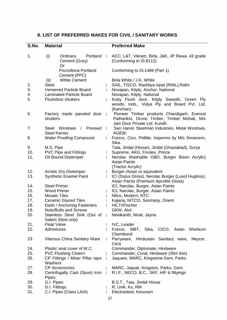
8. LIST OF PREFERRED MAKES FOR CIVIL / SANITARY WORKS
S.No. Material Preferred Make
1. (i) Ordinary Portland Cement (Grey) Or
Pozzollona Portland Cement (PPC) (ii) White Cement
: ACC, L&T, Vikram, Birla, J&K, JP Rewa, 43 grade (Conforming to IS:8112) Conforming to IS:1489 (Part 1) Birla White / J.K. White
2. Steel : SAIL, TISCO, Rashtiya Ispat (RINL),Rathi 3. Veneered Particle Board : Novapan, Kitply, Anchor, National 4. Laminated Particle Board Novapan, Kitply, National 5. Flushdoor shutters : Kutty Flush door, Kitply Swastik, Green Ply
woods, Inds., Vidya Ply and Board Pvt. Ltd. (Kanchan).
6. Factory made paneled door shutters
: Pioneer Timber products Chandigarh, Everest Pathankot, Drone Timber, Timber Mohali, M/s Jain Door Private Ltd. Kundli.
7. Steel Windows / Pressed Steel frames
: San Harvic Steelman Industries, Metal Windows, AGEW.
8. Water Proofing Compound : Fosroc, Cico, Pidilite. Impermo by M/s Snowcem, Sika.
9. M.S. Pipe Tata, Jindal (Hissar), Jindal (Ghaziabad), Surya 10. PVC Pipe and Fittings : Supreme, AKG, Finolex, Prince 11. Oil Bound Distemper : Nerolac Washable OBD, Burger Bison Acrylic)
Asian Paints (Tractor Acrylic)
12. Acrelic Dry Distemper : Burger /Asian or equivalent 13. Synthetic Enamel Paint : ICI (Dulux Gloss), Nerolac Burger (Luxol Hugloss),
Asian Paints (Premium Apcolite Gloss) 14. Steel Primer ICI, Narolac, Burger, Asian Paints 15. Wood Primer : ICI, Narolac, Burger, Asian Paints 16. Mosaic Tiles : Nitco, Modern, NTC 17. Ceramic Glazed Tiles : Kajaria, NITCO, Ssomany, Orient 18. Dash / Anchoring Fasteners : HILTI/Fischer 19. Nuts/Bolts and Screws GKW, Atul 20. Stainless Steel Sink (Out of
Salem Steel only) : Neelkanth, Nirali, Jayna
21. Float Valve : IVC, Leader 22. Admixtures : Fosroc, MBT, Sika, CICO, Asian Shielicon
Chembond 23. Viterous China Sanitary Ware : Parryware, Hindustan Sanitary ware, Neycer,
Cera 24. Plastic seat cover of W.C. Commander, Diplomate, Hindware 25. PVC Flushing Cistern : Commander, Coral, Hindware (Slim line) 26. CP Fittings / Mixer Pillar taps
Washers : Jaquare, MARC, Kingstone Gem, Parko
27. CP Accessories : MARC, Jaquar, Kingston, Parko, Gem. 28. Centrifugally Cast (Spun) Iron
Pipes : R.I.F., NECO, B.C., SKF, HIF & fittyings
29. G.I. Pipes B.S.T., Tata, Jindal Hissar 30. G.I. Fittings : R, Unik, Ks, RM 31. C.I. Pipes (Class LA/A) : Electrasteel, Kesoram

38
32. Gun metal Vaalves : Leader, Zoloto, Kilburn, CIM, Valves, Sant 33. Brass stop and Big Cock : Zoloto, Sant, L&K, Leaer 34. Stoneware pipes and Gully
traps Prefect, Hind
35. Mirror Glass : Atul, Modi Guard, Golden 36. Aluminium : Indal/Hindalco/Jindal 37. Masking tapes : Suncontrol/Wonder Polymer 38. Stainless steel screw for
fabrication and fixing of windows
: Kundan / Punja / Atul
39. Proposed Treatment on MS bracket
Galvanized brackets as per IS:4759-1996, 610 gms/sqm.(Microns) 80-90
40. Stainless steel bolts/washers and nuts
: Kundan / Punja / Atul
41. Stainless steel pressure plate screw
: Kundan / Punja / Atul
42. Stainless steel friction stay : Earl Behari / Anand 43. EPDM gasket : Roop / Anand 44. 6mm thick clear float glass Modi / St. Gobain / Gujarat Guardian Ltd. / Float
Glass of India 45. Weather silicon make and
grade : Dow Corning / Wacker / GE
46. PVC continuous fillet for periphery packing of glazing/curtain wall
: Roop / Anand / Forex Plastic
47. Stone Door / Window Frame : Mechanically Made Electrification Work 48. Wire : PHILCO / Finolex / Sundeep / Poly Cab
Plaza/Pytex/National/Ralison/RKG/Polycb/Batra-
Henlay/Havells
49. Switches / Sockets : Anchor / Precision / CPL / MK / Northwest /
Avanti / Vinay / Elley / Crabtree
50. MCB's, MCCBs, RCCBs,
ELCB's & MCB DBs
Legrand / ABB / L&T /Siemens / Havells / C&S /
Schneider / GE / Hagger / Anchor / Standard /
Action
51. Steel/PVC Conduit : BEC/AKG/ATUL/STEEL KRAFT/RKG
52. LT XLPE Aluminium
Armoured cables upto 1100v
: Plaza/Skytone/ National/Ralison/PYTEX/Paragon/
KEI

39
BUILDING MATERIALS & TECHNOLOGY PROMOTION COUNCIL
9. PROFORMA FOR AGREEMENT THIS AGREEMENT made this ………………………………………………….day of …………………………………………………………………………. between the BMTPC, established under the MoHUPA, having its Office at Core 5A, 1st Floor, India Habitat Centre, Lodhi Road, New Delhi – 110003 (which expression shall mean and include its successor or successors in office and assignee) acting through the Executive Director, BMTPC, New Delhi hereinafter called, ‘The Council’ on the one part and M/s/Sri ….................... ………………………………………………………….. hereinafter called the “Agency” which expression shall mean and include their heirs, executors, administrators and assignee) on the other part. WHEREAS, BMTPC, is desirous of construction of (NAME OF WORK) (hereinafter referred to as the “PROJECT”) on behalf of the (NAME OF OWNER/MINISTRY) (hereinafter referred to as “OWNER”), had invited tenders as per Tender documents vide NIT No. _____. AND WHEREAS (NAME OF CONTRACTOR) had participated in the above referred tender vide their tender dated _____ and BMTPC has accepted their aforesaid tender and award the contract for (NAME OF PROJECT) on the terms and conditions contained in its Letter of Intent No. ________ and the documents referred to therein, which have been unequivocally accepted by (NAME OF CONTRACTOR) vide their acceptance letter dated _______ resulting into a contract. NOW THEREFORE THIS DEED WITNESSETH AS UNDER: ARTICLE 1.0 – AWARD OF CONTRACT
a. SCOPE OF WORK
BMTPC has awarded the contract to (NAME OF CONTRACTOR) for the work of (NAME OF WORK) on the terms and conditions in its letter of intent No. __________ dated ________ and the documents referred to therein. The award has taken effect from (DATE) i.e. the date of issue of aforesaid letter of intent. The terms and expressions used in this agreement shall have the same meanings as are assigned to them in the “Contract Documents” referred to in the succeeding Article.

40
ARTICLE 2.0 – CONTRACT DOCUMENTS 2.1 The contract shall be performed strictly as per the terms and
conditions stipulated herein and in the following documents attached herewith (hereinafter referred to as “Contract Documents”).
a) BMTPC Notice Inviting Tender vide No. ________ date ______and BMTPC’s tender documents consisting of:
i) General Conditions of Contract (GCC) along with amendments/errata to GCC (if any) issued (Volume-I).
ii) Special Conditions of Contract including Appendices & Annexures, Volume-II.
iii) Bill of Quantities along with amendments/corrigendum of schedule items, if any
iv) ________________________________________________ v) ______________________________________________ vi) ______________________________________________
b) (NAME OF CONTRACTOR) letter proposal dated ________ and their subsequent communication:
i) Letter of Acceptance of Tender Conditions dated ______________
ii) _________________________________________________ iii) _________________________________________________
2.2 BMTPC’s detailed Letter of Intent No. _________ dated ____
including Bill of Quantities. Agreed time schedule, Contractor’s Organisation Chart and list of Plant and Equipments submitted by Contractor.
2.3 All the aforesaid contract documents referred to in Para 2.1 and 2.2 above shall form an integral part of this Agreement, in so far as the same or any part thereof column, to the tender documents and what has been specifically agreed to by BMTPC in its Letter of Intent. Any matter inconsistent therewith, contrary or repugnant thereto or deviations taken by the Contractor in its “TENDER” but not agreed to specifically by BMTPC in its Letter of Intent, shall be deemed to have been withdrawn by the Contractor without any cost implication to BMTPC. For the sake of brevity, this Agreement along with its aforesaid contract documents and Letter of Intent shall be referred to as the “Contract”.
ARTICLE 3.0 – CONDITIONS & CONVENANTS
3.1 The scope of Contract, Consideration, terms of payments, advance, security deposits, taxes wherever applicable, insurance, a greed time schedule, compensation for delay and all other terms and condition contained in BMTPC’s Letter of Intent No. __________ dated _____ are to be read in conjunction with other aforesaid contract documents. The contract shall be duly performed by the contractor strictly and faithfully in accordance with the terms of this

41
contract.
3.2 The scope of work shall also include all such items which are not specifically mentioned in the Contract Documents but which are reasonably implied for the satisfactory completion.
3.3 Contractor shall adhere to all requirements stipulated in the Contract documents.
3.4 Time is the essence of the Contract and it shall be strictly adhered to. The progress of work shall conform to agreed works schedule /contract documents and Letter of Intent.
3.5 This agreement constitutes full and complete understanding between the parties and terms of the presents. It shall supersede all prior correspondence to the extent of inconsistency or repugnancy to the terms and conditions contained in Agreement. Any modification of the Agreement shall be effected only by a written instrument signed by the authorized representative of both the parties.
3.6 The total contract price for the entire scope of this contract as detailed in Letter of Intent is Rs._________________ (Rupees _____________________________ only), which shall be governed by the stipulations of the contract documents
ARTICLE 4.0 – NO WAIVER OF RIGHTS
4.1 Neither the inspection by BMTPC or the Engineer-in-Charge or Owner or any of their officials, employees or agents nor order by BMTPC or the Engineer-in-Charge for payment of money or any payment for or acceptance of, the whole or any part of the work by BMTPC or the Engineer-in-Charge or any extension of time nor any possession taken by the Engineer-in-Charge shall operate as waiver of any provisions of the contract, or of any power herein reserved to BMTPC, or any right to damage herein provided, nor shall any waiver of any breach in the contract be held to be a waiver or any other or subsequent breach.
ARTICLE 5.0 – GOVERNING LAW AND JURISDICTION 5.1 The Laws applicable to this contract shall be the laws in force in India and jurisdiction of Delhi Court (s) only. 5.2 Notice of Default
Notice of default given by either party to the other party under the Agreement shall be in writing and shall be deemed to have been duly and properly served upon the parties hereto, if delivered against acknowledgment due or by FAX or by registered mail duly addressed to the signatories at the address mentioned herein above. IN WITNESS WHEREOF, the parties through their duly authorized representatives have executed these presents (execution whereof has been approved by the Competent
42
Authorities of both the parties) on the day, month and year first above mentioned at New Delhi. For and on behalf of: For and on behalf of:
SIGNED AND DELIVERED FOR AND ON BEHALF OF M/s /Shri ………………… ………………………………… IN THE PRESENCE OF WITNESS 1. 2. SIGNED AND DELIVERED FOR AND ON BEHALF OF BUILDING MATERIALS & TECHNOLOGY PROMOTION COUNCIL (BMTPC) IN THE PRESENCE OF WITNESS 1. 2.

43
INTEGRITY PACT
(To be submitted on Company letter head)
To, The Executive Director BMTPC, Core – 5A, 1st Floor, India Habitat Center, Lodhi Road, New Delhi: 110 0 14
Construction of 36 Demonstration Houses (G+2) on Design & Build basis with any of the following technologies Including on site Infrastructure Work at Sohan Kuan, Mauza Chakhaijyain, Biharsharif, Bihar
1. Stay in place EPS based double walls panel system with Infill concrete.
2. Monolithic construction with structural stay in place steel formwork system
3. Light Gauge Framed Steel Structure with suitable cladding and insulation system
Ref. No. : BMT/1/2016/ Biharsharif, Bihar Dated : ……………….. Dear Sir,
I/We acknowledge that BMTPC is committed to follow the principles thereof as enumerated in the Integrity Agreement enclosed with the tender/bid document.
I/We agree that the Notice Inviting Tender (NIT) is an invitation to offer made
on the condition that I/We will sign the enclosed integrity Agreement, which is an integral part of tender documents, failing which I/We will stand disqualified from the tendering process. I/We acknowledge that THE MAKING OF THE BID SHALL BE REGARDED AS AN UNCONDITIONAL AND ABSOLUTE ACCEPTANCE of this condition of the NIT.
I/We confirm acceptance and compliance with the Integrity Agreement in letter
and spirit and further agree that execution of the said Integrity Agreement shall be separate and distinct from the main contract, which will come into existence when tender/bid is finally accepted by BMTPC. I/We acknowledge and accept the duration of the Integrity Agreement, which shall be in the line with Article 1 of the enclosed Integrity Agreement.
I/We acknowledge that in the event of my/our failure to sign and accept the
Integrity Agreement, while submitting the tender/bid, BMTPC shall have unqualified, absolute and unfettered right to disqualify the Agency/bidder and reject the tender/bid is accordance with terms and conditions of the tender/bid.
Yours faithfully
(Duly authorized signatory of the Agency)

44
INTEGRITY PACT
To be signed by the bidder and same signatory competent / authorised to sign the relevant contract on behalf of BMTPC.
INTEGRITY AGREEMENT
This Integrity Agreement is made at ........ on this ........ day of ...........2016.
BETWEEN BMTPC represented through Executive Director, BMTPC, Core -5A, 1st Floor, India Habitat Centre, Lodhi Road, New Delhi, on behalf of Construction of Demonstration Housing Project at chak Hajiyain Biharsharif, Bihar. (Hereinafter referred as the ‘Principal/Owner’, which expression shall unless repugnant to the meaning or context hereof include its successors and permitted assigns)
AND ............................................................................................................. (Name and Address of the Individual/firm/Company) through .................................................................... (Hereinafter referred to as the (Details of duly authorized signatory) “Bidder/Contractor” and which expression shall unless repugnant to the meaning or context hereof include its successors and permitted assigns)
Preamble
WHEREAS the Principal / Owner has floated the Tender (NIT No. … …….………….….) (hereinafter referred to as “Tender/Bid”) and intends to award, under laid down organizational procedure, contract for: Construction of Demonstration Housing Project at chak Hajiyain Bihar Sharif, Bihar. Ref. No. BMT/CBM/1/2016/Bihar Dated: ………….. hereinafter referred to as the “Contract”.
AND WHEREAS the Principal/Owner values full compliance with all relevant laws of the land, rules, regulations, economic use of resources and of fairness/transparency in its relation with its Bidder(s) and Contractor(s).
AND WHEREAS to meet the purpose aforesaid both the parties have agreed to enter into this Integrity Agreement (hereinafter referred to as “Integrity Pact” or “Pact”), the terms and conditions of which shall also be read as integral part and parcel of the Tender/Bid documents and Contract between the parties.
NOW, THEREFORE, in consideration of mutual covenants contained in this Pact, the parties hereby agree as follows and this Pact witnesses as under:

45
Article 1: Commitment of the Principal/Owner 1) The Principal/Owner commits itself to take all measures necessary to
prevent corruption and to observe the following principles:
a) No employee of the Principal/Owner, personally or through any of his/her family members, will in connection with the Tender, or the execution of the Contract, demand, take a promise for or accept, for self or third person, any material or immaterial benefit which the person is not legally entitled to.
b) The Principal/Owner will, during the Tender process, treat all
Bidder(s) with equity and reason.
The Principal/Owner will, in particular, before and during the Tender process, provide to all Bidder(s) the same information and will not provide to any Bidder(s) confidential / additional information through which the Bidder(s) could obtain an advantage in relation to the Tender process or the Contract execution.
c) The Principal/Owner shall endeavor to exclude from the Tender
process any person, whose conduct in the past has been of biased nature.
2) If the Principal/Owner obtains information on the conduct of any of its
employees which is a criminal offence under the Indian Penal code (IPC)/Prevention of Corruption Act, 1988 (PC Act) or is in violation of the principles herein mentioned or if there be a substantive suspicion in this regard, the Principal/Owner will inform the Chief Vigilance Officer and in addition can also initiate disciplinary actions as per its internal laid down policies and procedures.
Article 2: Commitment of the Bidder(s)/Contractor(s)
1) It is required that each Bidder/Contractor (including their respective
officers, employees and agents) adhere to the highest ethical standards, and report to the Government / Department all suspected acts of fraud or corruption or Coercion or Collusion of which it has knowledge or becomes aware, during the tendering process and throughout the negotiation or award of a contract.
2) The Bidder(s)/Contractor(s) commit himself to take all measures
necessary to prevent corruption. He commits himself to observe the following principles during his participation in the Tender process and during the Contract execution:
a) The Bidder(s)/Contractor(s) will not, directly or through any other
person or firm, offer, promise or give to any of the Principal/Owner’s employees involved in the Tender process or execution of the Contract or to any third person any material or other

46
benefit which he/she is not legally entitled to, in order to obtain in exchange any advantage of any kind whatsoever during the Tender process or during the execution of the Contract.
b) The Bidder(s)/Contractor(s) will not enter with other Bidder(s) into any
undisclosed agreement or understanding, whether formal or informal. This applies in particular to prices, specifications, certifications, subsidiary contracts, submission or non-submission of bids or any other actions to restrict competitiveness or to cartelize in the bidding process.
c) The Bidder(s)/Contractor(s) will not commit any offence under the
relevant IPC/PC Act. Further the Bidder(s)/Contract(s) will not use improperly, (for the purpose of competition or personal gain), or pass on to others, any information or documents provided by the Principal / Owner as part of the business relationship, regarding plans, technical proposals and business details, including information contained or transmitted electronically.
d) The Bidder(s)/Contractor(s) of foreign origin shall disclose the names
and addresses of agents / representatives in India, if any. Similarly Bidder(s)/ Contractor(s) of Indian Nationality shall disclose names and addresses of foreign agents/representatives, if any. Either the Indian agent on behalf of the foreign principal or the foreign principal directly could bid in a tender but not both. Further, in cases where an agent participate in a tender on behalf of one manufacturer, he shall not be allowed to quote on behalf of another manufacturer along with the first manufacturer in a subsequent/parallel tender for the same item.
e) The Bidder(s)/Contractor(s) will, when presenting his bid, disclose
any and all payments he has made, is committed to or intends to make to agents, brokers or any other intermediaries in connection with the award of the Contract.
3) The Bidder(s)/Contractor(s) will not instigate third persons to commit
offences outlined above or be an accessory to such offences. 4) The Bidder(s)/Contractor(s) will not, directly or through any other
person or firm indulge in fraudulent practice means a willful misrepresentation or omission of facts or submission of fake/forged documents in order to induce public official to act in reliance thereof, with the purpose of obtaining unjust advantage by or causing damage to justified interest of others and/or to influence the procurement process to the detriment of the Government interests.
5) The Bidder(s)/Contractor(s) will not, directly or through any other person or
firm use Coercive Practices (means the act of obtaining something, compelling an action or influencing a decision through intimidation, threat or the use of force directly or indirectly, where potential or actual injury

47
may befall upon a person, his/ her reputation or property to influence their participation in the tendering process).
Article 3: Consequences of Breach
Without prejudice to any rights that may be available to the Principal/Owner under law or the Contract or its established policies and laid down procedures, the Principal/Owner shall have the following rights in case of breach of this Integrity Pact by the Bidder(s)/Contractor(s) and the Bidder/ Contractor accepts and undertakes to respect and uphold the Principal/Owner’s absolute right:
1) If the Bidder(s)/Contractor(s), either before award or during execution of
Contract has committed a transgression through a violation of Article 2 above or in any other form, such as to put his reliability or credibility in question, the Principal/Owner after giving 14 days notice to the contractor shall have powers to disqualify the Bidder(s)/ Contractor(s) from the Tender process or terminate/determine the Contract, if already executed or exclude the Bidder/Contractor from future contract award processes. The imposition and duration of the exclusion will be determined by the severity of transgression and determined by the Principal/Owner. Such exclusion may be forever or for a limited period as decided by the Principal/Owner.
2) Forfeiture of EMD/Performance Guarantee/Security Deposit: If the
Principal/Owner has disqualified the Bidder(s) from the Tender process prior to the award of the Contract or terminated/determined the Contract or has accrued the right to terminate/determine the Contract according to Article 3(1), the Principal/Owner apart from exercising any legal rights that may have accrued to the Principal/Owner, may in its considered opinion forfeit the entire amount of Earnest Money Deposit, Performance Guarantee and Security Deposit of the Bidder/Contractor.
3) Criminal Liability: If the Principal/Owner obtains knowledge of conduct of
a Bidder or Contractor, or of an employee or a representative or an associate of a Bidder or Contractor which constitutes corruption within the meaning of IPC Act, or if the Principal/Owner has substantive suspicion in this regard, the Principal/Owner will inform the same to law enforcing agencies for further investigation.
Article 4: Previous Transgression
1) The Bidder declares that no previous transgressions occurred in the last 5
years with any other Company in any country confirming to the anticorruption approach or with Central Government or State Government or any other Central/State Public Sector Enterprises in India that could justify his exclusion from the Tender process.
2) If the Bidder makes incorrect statement on this subject, he can be
disqualified from the Tender process or action can be taken for banning of business dealings/ holiday listing of the Bidder/Contractor as deemed fit by the Principal/ Owner.

48
3) If the Bidder/Contractor can prove that he has resorted / recouped the
damage caused by him and has installed a suitable corruption prevention system, the Principal/Owner may, at its own discretion, revoke the exclusion prematurely.
Article 5: Equal Treatment of all Bidders/Contractors/Subcontractors
1) The Bidder(s) / Contractor(s) undertake(s) to demand from all
subcontractors a commitment in conformity with this Integrity Pact. The Bidder/Contractor shall be responsible for any violation(s) of the principles laid down in this agreement/Pact by any of its Sub- contractors/sub-vendors.
2) The Principal/Owner will enter into Pacts on identical terms as this one
with all Bidders and Contractors. 3) The Principal/Owner will disqualify Bidders, who do not submit, the duly
signed Pact between the Principal/Owner and the bidder, along with the Tender or violate its provisions at any stage of the Tender process, from the Tender process.
Article 6- Duration of the Pact
This Pact begins when both the parties have legally signed it. It expires for the Contractor/Vendor 12 months after the completion of work under the contract or till the continuation of defect liability period, whichever is more and for all other bidders, till the Contract has been awarded. If any claim is made/lodged during the time, the same shall be binding and continue to be valid despite the lapse of this Pacts as specified above, unless it is discharged/determined by the Competent Authority, BMTPC. Article 7- Other provisions
1) This Pact is subject to Indian Law, place of performance and
jurisdiction is the Head quarters of the Division of the Principal/Owner, who has floated the Tender.
2) Changes and supplements need to be made in writing. Side agreements
have not been made. 3) If the Contractor is a partnership or a consortium, this Pact must be signed
by all the partners or by one or more partner holding power of attorney signed by all partners and consortium members. In case of a Company, the Pact must be signed by a representative duly authorized by board resolution.
4) Should one or several provisions of this Pact turn out to be invalid; the
remainder of this Pact remains valid. In this case, the parties will strive to come to an agreement to their original intensions.

49
5) It is agreed term and condition that any dispute or difference arising
between the parties with regard to the terms of this Integrity Agreement / Pact, any action taken by the Owner/Principal in accordance with this Integrity Agreement/ Pact or interpretation thereof shall not be subject to arbitration.
Article 8- LEGAL AND PRIOR RIGHTS
All rights and remedies of the parties hereto shall be in addition to all the other legal rights and remedies belonging to such parties under the Contract and/or law and the same shall be deemed to be cumulative and not alternative to such legal rights and remedies aforesaid. For the sake of brevity, both the Parties agree that this Integrity Pact will have precedence over the Tender/Contact documents with regard any of the provisions covered under this Integrity Pact.
IN WITNESS WHEREOF the parties have signed and executed this Integrity Pact at the place and date first above mentioned in the presence of following witnesses: ............................................................... (For and on behalf of Principal/Owner) ............................................................... (For and on behalf of Bidder/Contractor)
WITNESSES:
1) .............................................. 2) ..............................................
……………………………….. ………………………………..
(Signature, Name & Address) (Signature, Name & Address)

50
Construction of 36 Demonstration Houses (G+2) on Design & Build basis with any of the following technologies Including on site Infrastructure Work at Sohan Kuan, Mauza Chakhaijyain, Bihar Sharif, Bihar
1. Stay in place EPS based double walled panel system with
infill concrete. 2. Monolithic construction with structural stay in place CR
steel specially designed formwork system 3. Light Gauge Steel Framed Structure with suitable
cladding and insulation system
Composite Work (Ref. No. BMT/CBM/1/2016/BIHAR)
Part-B
Financial Bid

51
fuekZ.k lkexzh ,oa izkS|ksfxdh lao)Zu ifj”kn
vkokl vkSj ‘kgjh xjhch mi’keu ea=ky;] Hkkjr ljdkj
Building Materials & Technology Promotion Council Ministry of Housing & Urban Poverty alleviation, Government of India
Core-5A, 1st Floor, India Habitat Centre, Lodhi Road, New Delhi Phone: +91-11-24636705, Fax: +91-11-24642849
Website:www.bmtpc.org Email:[email protected]
Name of Work: Construction of 36 Demonstration Houses (G+2) on Design & Build basis
with any of the following technologies Including on site Infrastructure Work at Sohan Kuan, Mauza Chakhaijyain, Biharsharif, Bihar
1. Stay in place EPS based double walled panel system with infill concrete.
2. Monolithic construction with structural stay in place CR steel specially designed formwork system
3. Light Gauge Steel Framed Structure with suitable cladding and insulation system
Bill of Quantity (BOQ)
SCHEDULE OF WORK
Sl. No.
Description of Work Total Built up
area
Unit Rate in Rs. Amount (in Rs.) In
Figures In
Words
A Housing (Tobe quoted on Built up Area rate per sqft)
1. Construction of three storied (G+2) 36 nos houses using ………… …………. ……………… ……………… ……
System Technology as per specifications and approved drawings, including Mumty at terrace complete in all respect. [Note : The built-up area of the unit or Total area may vary from drawing enclosed due to change in wall thickness as per design requirement, however the minimum carpet area of unit & circulation area
17641.00 Sqft

52
Sl. No.
Description of Work Total Built up
area
Unit Rate in Rs. Amount (in Rs.) In
Figures In
Words
(Corridor & Staircase) need to be maintained same as per enclosed drawing]
Total in Figures
Total in Words
Rupees only
Signature of Agency
Name:_________________________
Address:_________________________
_________________________
Tel No. _________________________
Fax No. _________________________
Email_________________________

53
PART B (Item Rate) SCHEDULE OF WORK ON SITE INFRASTRUCTURE WORKs Sl. No.
Particular of Item Qty. Unit Rate Amount
SUB HEAD -1
Boundary Wall
1. Earth work in excavation in foundation trenches or drains(not exceeding 1.5 m in width or 10 sqm on plan) including dressing of sides and ramming of bottoms, lift up to 1.5 m . including getting out the excavated soil and disposal of surplus excavated soil as directed, within a lead of 50 m.
All kind of Soil
75.04 cum
2. Providing and laying in position cement concrete of specified grade excluding the cost of centering and shuttering-all work up to plinth level.
1:4:8 (1 Cement : 4 coarse sand : 8 graded stone aggregate 40 mm nominal size).
10.01 Cum
3. Brick work with bricks of class designation 100A in foundations and plinth in :
Cement mortar 1:6 (1 cement : 6 coarse sand) 55.23 Cum
4.a* Cost of Panel (As per Technology adopted) including cost of staples etc if required
182.10 sqm
4.b* Providing and laying in position cement concrete of specified grade excluding the cost of centering and shuttering - All work up to plinth level :
4.c* 1:1½:3 (1 Cement: 1½ coarse sand: 3 graded stone aggregate 20 mm nominal size)
16.41 cum
4.d* Reinforcement for R.C.C. work at all levels including straightening, cutting, bending, placing in position and binding all complete.
Thermo-Mechanically Treated bars 1000.00 cum
OR
4a* Half brick masonry with bricks of class designation 100A in superstructure above plinth level up to floor V level in: Cement mortar 1:4.
182.10 Sqm
4b* Extra for providing and placing in position 2 Nos, 6 mm dia , MS bars at every third course of half brick masonry
182..10 Sqm
11 5. Providing and laying damp-proof course 50mm thick with cement concrete 1:2:4 (1 cement : 2 coarse sand : 4 graded stone aggregate 20mm nominal size).
27.92 Sqm
12 6. Steel work in built up tubular trusses including cutting, hoisting, fixing in position and applying a priming coar of approved steel primer, welded and bolted including special shaped washers etc. complete:
Hot finished welded type tubes 408.00 Kg
13 7. Providing and laying cement concrete in retaining walls, return walls, walls (any thickness) including attached pilasters, columns, piers, abutments,pillars,post.struts,buttresses, string or lacing courses,parapets, coping,bed blocks, anchor blocks, plinth window sills, fillets etc. upt floor five level excluding the cost of centring,shuttering and finishing:
1:2:4 (1 Cement :2 coarse sand :4 graded stone aggregate 20 mm nominal size)
1.40 sqm
14 8. 12mm cement plaster of mix 1:6(1cement :6 fine sand) 436.90 Sqm
9. Finishing walls with water proofing cement paint of required shade :

54
15 New work (Two or more coats applied @ 3.84 kg/10 sqm) 388.48 Sqm
TOTAL OF SUB HEAD-1
NOTE: * The bidder may quote for either of the Item No 4 (a, b & c) or 4 (a & b) and calculate the
total of Sub Head -1 accordingly SUB HEAD -2
EARTH FILLING
10 Earth work in excavation by mechanical means (Hydraulic excavator) / manual means over areas (exceeding 30cm in depth. 1.5 m in width as well as 10 sqm on plan) including disposal of excavated earth, lead up to 50m and lift up to 1.5m, disposed earth to be levelled and neatly dressed. All kinds of soil
666.38 Cum
11 Transportation of above earth with all lead and lift (UPTO 5km lead) including loading unloading and stacking.
666.38 Cum
12 Preparation and consolidation of sub grade with power road roller of 8 to 12 tonne capacity after excavating earth to an average of 22.5 cm depth, dressing to camber and consolidating with road roller including making good the undulations etc. and re-rolling the sub grade and disposal of surplus earth with lead up to 50 metres.
666.38 Cum
TOTAL SUB HEAD-2
SUBHEAD-3
ROAD AND PAVEMENT
13 Earth work in excavation in foundation, trenches etc. including dressing of sides and ramming of bottoms, including getting out the excavated material, refilling after laying pipe/ foundation and disposal of surplus excavated material at a lead up to 50m suitable site as per direction of Engineer for following depths, below natural ground / Road top level.
14 Depth up to 1.5 m 50.00 Cum
15 Preparation and consolidation of sub grade with power road roller of 8 to 12 tonne capacity after excavating earth to an average of 22.5 cm depth, dressing to camber and consolidating with road roller including making good the undulations etc. and re-rolling the sub grade and disposal of surplus earth with lead up to 50 metres.
359..10 Sqm
16 Providing and laying in position cement concrete of specified grade excluding the cost of centering and shuttering-all work up to plinth level.
17 1:4:8 (1 Cement : 4 coarse sand : 8 graded stone aggregate 40 mm nominal size).
53.87 Cum
18 Providing and laying in position cement concrete of specified grade excluding the cost of centring and shuttering-all work up to plinth level.
19 1:1½:3 (1 Cement: 1½ coarse sand: 3 graded stone aggregate 20 mm nominal size)
13.75 cum
Interlocking Paver
20 Providing and laying 60mm thick factory made cement concrete interlocking paver block of M -30 grade made by block making machine with strong vibratory compaction, of approved size, design & shape, laid in required colour and pattern over and including 50mm thick compacted bed of coarse sand, filling the joints with fine sand etc. all complete as per the direction of Engineer-in-charge.
160.28 Sqm
TOTAL OF SUB HEAD-3

55
SUB HEAD -4
Septic Tank 3 Nos of sizes given in drawing
21 Earth work in excavation in foundation trenches or drains(not exceeding 1.5 m in width or 10 sqm on plan) including dressing of sides and ramming of bottoms, lift up to 1.5 m . including getting out the excavated soil and disposal of surplus excavated soil as directed, within a lead of 50 m.
All kind of Soil
Depth up to 1.5 m 91.78 Cum
22 Providing and laying in position cement concrete of specified grade excluding the cost of centring and shuttering – All work up to plinth level :
a 1:4:8 (1 Cement : 4 coarse sand : 8 graded stone aggregate 40 mm nominal size).
6.12 Cum
b 1:2:4 (1 cement : 2 coarse sand : 4 graded stone aggregate 20 mm nominal size21)
6.12 Cum
23 Providing and laying in position specified grade of reinforced cement concrete excluding the cost of centring, shuttering, finishing and reinforcement – All work up to plinth level :
1:1½:3 (1 cement : 1½ coarse sand : 3 graded stone aggregate 20 mm nominal size)
7.02 Cum
24 Reinforcement for R.C.C. work at all levels including straightening, cutting, bending, placing in position and binding all complete.
Thermo-Mechanically Treated bars 380.00 Kg
25 Brick work with bricks of class designation 75 in foundation and plinth in:
Cement mortar 1:6 (1 cement : 6 coarse sand) 23.58 Cum
26 Half brick masonry with brick of class designation 75 in foundations and plinth in :
cement mortar 1:4 (1 cement : 4 coarse sand) 6.48 Sqm
27 Cement plastering including T&P, scaffolding, material and complete labpour, including cost of water, curing, racking of joints etc. with 15 mm cement plaster on rough side of single or half brick wall finished with a floating coat of neat cement of mix : CM 1:4
110.99 Sqm
28 Centring and shuttering up to two stories or height up to 7.5 metre above plinth level including strutting, propping etc. and removal of form for :
29 Suspended floors, roofs, landings, balconies and access platform.
41.49 Sqm
30 Providing and fixing in position pre-cast R.C.C. manhole cover and frame of required shape and approved quality
31 Circular shape 500 mm internal diameter 6.00 Nos
TOTAL SUB HEAD-4
SUB HEAD -5
HORTICULTURE
32 Supplying and stacking at site dump manure from approved source including all lead and lifts (manure measured in stacks will be reduced by 8% for payment) - screened through sieve of IS designation 20 mm.
25.02 Cum
33 Supplying & stacking sludge at site including royalty & carriage will all leads & lifts (sludge manure measured in stacks will be reduced by 8 % for payment)
25.02 Cum
34 Spreading of sludge / damp manure of / and good earth in required thickness (cost of sludge/ damp manure or / land good earth to paid separately)
30.04 Cum
35 Grassing with 'Doobs' grass including watering and maintenance of the lawn for 30 days or more till the grass

56
forms a thick lawn free from weeds and fit for moving including supplying good earth if needed.
In rows 15 cm apart in either direction 50.90 Sqm
36 Supply and planting following in poly bags / earthen pots well branched, well established & free from disease of 600 mm min. height shrubs at site in 0.45 m dia holes, 0.45 m deep dug in the ground, mixing the soil with decayed farm yard/sludge manure, backfilling the hole watering etc as required.
Plants 50.00 each
TOTAL SUB HEAD-5
SUB HEAD – 6
External Water Supply & Sewerage
37 Providing and fixing 3 layer PP-R (Poly propylene Random copolymer) pipes, U V stabilized & anti – microbial fusion welded, having thermal stability for hot & cold water supply, including all PP – R plain & brass threaded polypropylene random fittings, including trenching, refilling & testing of joints complete as per direction of Engineer in Charge.
PN – 16 Pipe, 50 mm OD (SDR – 7.4) 182.88 mtr
38 Providing and fixing brass ferrule with C.I. mouth cover including boring and tapping the main :
20 mm nominal bore 36.00 each
39 Providing and fixing gun metal gate valve with C.I. wheel of approved quality (screwed end) :
50 mm nominal bore. 6.00 each
SEWERAGE
40 Providing and fixing square-mouth S.W. gully trap grade ‘A’’ complete with Precast RCC cover and frame of approved make 300 x 300 mm internal size:
100x 100 size P Type
With bricks class designation 75 36.00 each
41 Constructing brick masonry manhole in cement mortar 1:4 ( 1 cement : 4 coarse sand ) R.C.C. top slab with 1:2:4 mix (1 cement : 2 coarse sand : 4 graded stone aggregate 20 mm nominal size), foundation concrete 1:4:8 mix (1 cement : 4 coarse sand : 8 graded stone aggregate 40mm nominal size) inside plastering 12mm thick with cement mortar 1:3 (1 cement : 3 coarse sand) finished with floating coat of neat cement and making channels in cement concrete 1:2:4 (1 cement : 2 coarse sand : 4 graded stone aggregate 20mm nominal size) finished with a floating coat of neat cement complete as per standard design :
A Inside size 90x80 cm and 45 cm deep including Precast RCC manhole cover (LD – 2.5) and frame of required shape and approved quality
With bricks with class designation 75 12.00 each
B Inside size 120x90 cm and 90 cm deep including precast RCC manhole cover (LD- 2.5) and frame of required shape and approved quality
With bricks class designation 75 4.00 each
42 Providing and Fixing PVC Soil / vent / waste SWR pipe of including diameter conforming to IS – 13592:1992 and IS 4985:2000 to withstand 6 Kg/cm2 pressure including necessary fixtures and fittings, such a bends, trees, single junctions, double junction and joining with rubber rings and lubricants on wall by means of clips or in ground including

57
necessary excavation, laying filling, tranch testing etc. complete
A 110 mm dia
43.20 mtr
B 150 mm dia 125.80 mtr
43 Providing and laying cement concrete 1:5:10 (1 cement : 5 coarse sand : 10 graded stone aggregate 40 mm nominal size) all-round S.W. pipes including bed concrete as per standard design :
A 110 mm dia
43.20 Mtr
B 150 mm dia 125.80 mtr
TOTAL SUB HEAD-6
SUB HEAD - 7
DRAINAGE & DISPOSAL
44 Earth work in excavation by mechanical means (Hydraulic excavator) / manual means in foundation trenches or drains (not exceeding 1.5 m in width or 10 sqm on plan), including dressing of sides and ramming of bottoms, lift up to 1.5 m, including getting out the excavated soil and disposal of surplus excavated soil as directed, within a lead of 50 m. All kinds of soil.
In all types soils/ saturated soil such as moorum, sand, sandy silt clay, black cotton soil, kankar, etc.
Depth up to 1.5 m 55.06 cum
45 Providing and laying in position cement concrete of specified grade excluding the cost of centring and shuttering - All work up to plinth level :
1:4:8 (1 Cement : 4 fine/ coarse sand : 8 graded stone aggregate 40 mm nominal size).
11.01 Cum
46 Random rubble masonry with hard stone in foundation and plinth including levelling up with cement concrete 1:6:12 (1 cement : 6 coarse sand : 12 graded stone aggregate 20 mm nominal size) up to plinth level with :
Cement mortar 1:6 (1 cement : 6 coarse sand) 22.264 cum
47 Providing and laying in position cement concrete of specified grade excluding the cost of centring and shuttering - All work up to plinth level :
1:3:6 (1 cement : 3 coarse sand : 6 graded stone aggregate 20 mm nominal size21)
3.63 cum
48 12 mm cement plaster on rough side of wall finished with a floating coat of neat cement of mix :
1:4 (1 cement : 4 fine/ coarse sand) 72.60 sqm
49 Providing, hoisting and fixing up to floor five level precast reinforced cement concrete work in string courses, bands, copings, bed plates, anchor blocks, plain window sills and the like, including the cost of required centering, shuttering but excluding cost of reinforcement, with 1:2:4 (1 cement: 2 coarse sand: 4 graded stone aggregate 20 mm nominal size).
Drain Covering 4.60 Cum
50 Constructing brick masonry road gully chamber 45x45x77.5 cm with bricks in cement mortar 1:4 (1 cement : 4 coarse sand ) with precast R.C.C. vertical grating complete as per standard design : With common burnt clay F.P.S. (non modular) bricks of class designation 7.5
4.00 each
51 Constructing brick masonry road gully chamber 110x50x77.5 cm with bricks in cement mortar 1:4 (1 cement : 4 coarse sand) including 500x450 mm pre-cast R.C.C. horizontal grating with frame and vertical grating complete as per standard design : With common burnt clay F.P.S. (non modular) bricks of class designation 7.5
1.00 each

58
52 Providing and Fixing PVC Soil / Vent / waste SWR pipe of required diameter confirming ti IS:13592-1992 and IS:4985-2000 to withstand 6 Kg/cm2 presure including necessary fixture and fitting, such as bend, Tees, single junctions, double junction and jointing with rubber ring and lubrications in ground including necessary excavation, laying , filling trenches testing etc. complete
A 110mm dia
110.00 Mtr
B 150mm dia 20.00 mtr
53 Providing and laying cement concrete 1:5:10 (1 cement : 5 coarse sand : 10 graded stone aggregate 40 mm nominal size) all-round S.W. pipes including bed concrete as per standard design :
A 110mm dia
110.00 Mtr
B 150mm dia 20.00 Mtr
TOTAL SUB HEAD-7
SUB HEAD - 8
PLINTH PROTECTION
54 Making plinth protection 50 mm thick of cement concrete 1:3:6 (1 cement :3 coarse sand : 6 graded stone aggregate 20 mm nominal size) over 75 mm thick bed of dry brick ballast 40 mm nominal size, well rammed and consolidated and grouted with fine sand, including finishing the top smooth.
180.00 Sqm
TOTAL SUB HEAD-8
SUB HEAD - 9
EXTERNAL ELECTRICAL WORKS
55 P/Laying XLPE insulated / P.V.C. sheathed cable of 1.1 KV grade with aluminium conductor Armoured of IS:7098-I/1554-1 approved make in ground as per IS:1255 including excavation of 30cmx75cm size trench, 25 cm thick under layer of sand, 2nd class bricks covering, refilling earth, compaction of earth, making necessary connection, testing etc. as required of size.
A 35.0 Sq.mm
3.5 core 150.00 mtr
B 6.0 Sq.mm
2 core 800.00 Mtr
C 4.0 Sq.mm
2 core 600.00 mtr
56 Supplying and making one end termination with heavy duty single compression brass gland SIBG type, aluminium lugs duly crimped with crimping tool, PVC tape etc for following size of Armoured PVC insulated & PVC sheathed/ XLPE aluminium conductor cable of 1100 volt grade as required of size.
A 3 x 35.0 sq.mm
8.00 Set
B 2 x 6.0 sq.mm 70.00 set
C 2 x 4.0 sq.mm 70.00 set
Feeder Pillar
57 Supply and fixing of floor mounting, totally enclosed, compartmentalized, cubical, dust, vermin proof and outdoor type. Feeder pillar fabricated out of 2 mm thick cold rolled carbon annealed, sheet steel, internally strengthened with

59
angle iron frame work with following incoming and outgoing feeders (fabricated out of 2 mm CRCA Sheet steel) including making connection / inter-connections with lugs / glands crimping tools, testing and commissioning of following items inside the panel:
Incommer
1 No. 200 Amp. 4 polse MCCB (25 Ka) with ON/OFF indications metre
Indication
Three (3) Nos. phase indicating (R.Y and B) lamps with protection 2A SP MCB's for protection having lens and lamp.
Outgoing
One (1) NO. 160 Amp. 4 pole MCCb (16 KA) with ON/OFF indications in the in front 15 nos. 32 A D.P. MCB (10 KA)
Control
4 Pole Contractor with a thermal rating of 32 - 1 no.
Time Switch with Daily dial, suitable for operation on 230 Volt, Single phase, 50 Hz, AC supply - 1 No.
Auto - Manual Selector switch - 1 No.
On / Off Push Buttons - 4 Nos. 2.00 Nos.
58 Plate Earthing as per IS:3043 with copper Earth plate of size 600mm x 600mm x 3.0mm by embodying 3 to 4 mtr. below the ground level with 20 mm dia. G.I. 'B' class watering Pipe including all accessories like nut, bolts, reducer, nipple ,wire meshed funnel, and C.C. finished chamber covered with hinged type with locking arrangement C.I. Cover, C.I. Frame of size300mm x 300mm complete with alternate layers of salt and coke/charcoal, testing of earth resistance as required.
2.00 set
59 Supplying of 75 mm dia (nominal) (Medium class), 4.5 meter length (including accessories) complete with base plate and nipple including two coats of black bituminous paint up to 1 mtr. From bottom and two coat of aluminium paint above ground level etc. complete as required.
Detail of pole is given below
Planting depth - 1 Mtr.
Height above ground level - 3.5 Mtr. 18.00 each
60 P & F IP-54 protected street light luminaire on existing bracket suitable for HPMV lamp, made out from powder coated single piece die cast aluminium housing electrochemically brightened and anodized aluminium reflector, UV stabilised acrylic bowl cover and accessories like copper ballast, electronic igniter, capacitor, holder prewired up to terminal block etc. as required including making connection testing etc. as required (without lamp)
1 X 80 Watt 18.00 each
61 Earth work in excavation in foundation, trenches etc. including dressing of sides and ramming of bottoms, including getting out the excavated material, refilling after laying pipe/ foundation and disposal of surplus excavated material at a lead up to 50m suitable site as per direction of Engineer for following depths below natural ground / Road top level.
In all types soils/ saturated soil such as moorum, sand, sandy silt, clay, black cotton soil, kankar, etc.
Depth up to 1.5 m 16.80 Cum
62 Providing and laying in position cement concrete of specified grade excluding the cost of centering and shuttering - All work up to plinth level :
1:2:4 (1 Cement : 2 coarse sand : 4 graded stone aggregate 6.00 cum

60
40 mm nominal size).
TOTAL SUB HEAD 9
GRAND TOTAL (Sub Head 1 to 9)
Signature of Agency
Name:_________________________
Address:_________________________
_________________________
Tel No. _________________________
Fax No. _________________________
Email_________________________
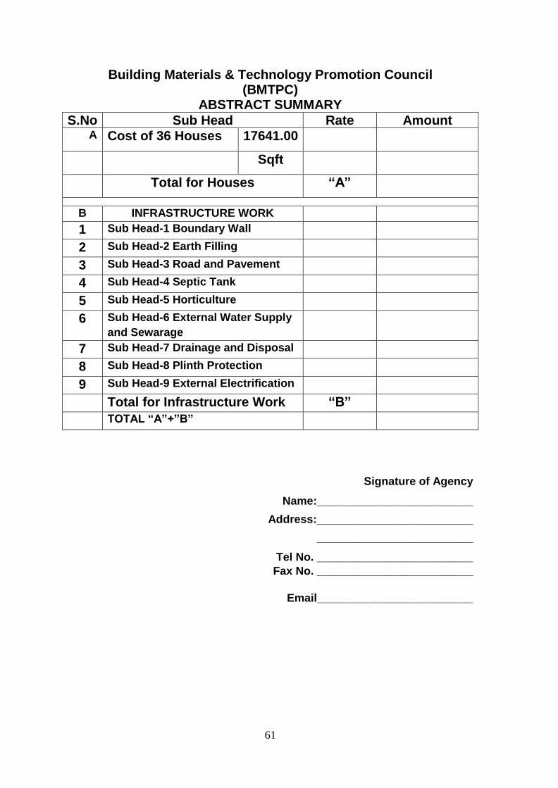
61
Building Materials & Technology Promotion Council (BMTPC)
ABSTRACT SUMMARY
S.No Sub Head Rate Amount A Cost of 36 Houses 17641.00
Sqft
Total for Houses “A”
B INFRASTRUCTURE WORK
1 Sub Head-1 Boundary Wall
2 Sub Head-2 Earth Filling
3 Sub Head-3 Road and Pavement
4 Sub Head-4 Septic Tank
5 Sub Head-5 Horticulture
6 Sub Head-6 External Water Supply
and Sewarage
7 Sub Head-7 Drainage and Disposal
8 Sub Head-8 Plinth Protection
9 Sub Head-9 External Electrification
Total for Infrastructure Work “B”
TOTAL “A”+”B”
Signature of Agency
Name:_________________________
Address:_________________________
_________________________
Tel No. _________________________
Fax No. _________________________
Email_________________________

62
Annexure – 1a Name of the Technology – “Stay in place EPS based double walled panel with in
fill concrete”
Brief Description
“Stay in place EPS based double walled panel with in fill concrete system” is an
insulating shuttering kit for whole building based on a three-dimensional lattice made of
galvanized steel wire. The lattice is filled with materials of different nature to serve as
formwork. The basic structure of the “Stay in place EPS based double walled panel with
in fill concrete system” is steel wire lattice. At the exterior sides of the lattice, infill
panels are inserted, which transform the lattice into a closed structure that can be filled
with concrete. The type of infill panels used depends on the purpose of the wall: load
bearing or not, insulated or otherwise, etc. The steel wire also acts as armature and
anchoring for the finished material and it holds reinforcement bars in place during
concrete filling.
Description of the components is as follows:
3D lattice (2.2 mm Ø galvanized steel wire)
Infill panels (EPS)
Structural filler (concrete)
Finishing (plastering)
Typical detail of a wall is shown in Fig.1.
Fig. 1 “Stay in place EPS based double walled panel with in fill concrete system” Wall

63
Modules
Type of Modules
Depending on the internal and external material, the walls may be divided into following
types:
(i) Inside & outside insulation (EPS) strips symmetrical and asymmetrical
(ii) Inside board and outside insulation (EPS) strips
(iii) Inside & outside board strips
(iv) Inside & outside insulation strips
Stay in place EPS based double walled panel with in fill concrete system floors and roofs
may be plain, one and two-way slabs; as per requirement.
However, only EPS Based double walled panels are proposed for this project.
Detail of these modules is shown in Figs. 2 to 5.
Fig. 2 Inside & outside insulation strips Fig. 3 Inside board & outside
insulation strips
Fig. 4 Inside & outside board strips Fig. 5 Module with insulation as core
Designation of Modules
The format used for designation of modules is as follows:
Walls: SX1_X2X3_X4X3_X5
Floors FX6
Where

64
X1= thickness of steel lattice in cm = 6, 8, 10, 15, 20, 25, 30, 35, 40, 45 or
50
X2 = thickness of internal insulation in cm = 4
X3 = type of shuttering material i.e. EPS or FCB
X4 = thickness of external insulation in cm = 4
X5 = SW (single wire) or 2SW in absence of 1 cm protruding wire
on inside and both sides of the panels respectively as shown in
Figs 6 & 7.
X6 =thickness of the floor measured from the 1 cm protruding wire
up to top of the interjoist from 15 to 40 cm as shown in
dimension X in Fig. 8.
Fig. 6 With protruding lattice Fig. 7 Without protruding lattice
Fig. 8 Floor module with EPS inter joist to create a girder-slab floor
Description of the Components
Steel Lattice
The steel wire frame, formwork for the walls, shall be available in panels of different
dimensions as follows:
Height: in multiples of 15 cm, with a max. of 12 m
Length: in multiples of 10 cm, with a max. of 1.2 m
Thickness: Max. 50 cm, depending on the type of wall /roof required

65
Detail of steel lattice is shown in Figs. 9 to 11.
Fig. 9 Vertical cross-section of steel wire lattice.
Figure on right one side without 1 cm protruding lattice (single wire frame on one side).
1 indicates position of insulation strips and 2 the position of sheet strips
Fig. 10 Cross-serction up to 50 cm Fig. 11 Modular dimension of module
The details of one-way girder-slab floor are as follows:
The center to center distance between the ribs is in multiples of 15 cm
The width of the ribs is 15 cm or in multiples thereof.

66
The details of two-way girder-slab floor are as follows:
The center to center distance between the ribs is in multiples of 15 cm on one side and
10cm on the other side
The width of the ribs is 15 cm or in multiples thereof on one side and 10cm on the other
side.
The details of these slabs are shown in Figs. 12 to 16.
Fig. 12 Module for a deck slab
Fig. 13 EPS block for floor module Fig. 14 One-way girder-slab floor
Fig. 15 One-way girder-slab floor Fig. 16 Two-way girder-slab floor

67
Modulation of Lattice
i. External and internal walls shall be drawn in elevation and in section using the
modular dimensions (15 cm high & 10 cm wide) of the lattice as a unit
ii. The corners of rectangular units shall correspond to the corners of the lattice.
Curves, pitches and starting points shall be determined as required. The top and
sides of the openings shall be closed with infill panels.
iii. The level of the upper side of the unfinished floor slabs shall correspond to that of a
vertical 15 cm modular unit, so that the walls shall be continued in 15 cm units.
iv. In the ground plan, lattices shall be directly placed next to one another. The
planning module of 10 cm shall always be used.
v. Every effort shall be made to ensure that the lattices are assembled in such a way
that their length is always in multiple of 15 cm and height in multiples of 10 cm.
Detail of the modulation is shown in Fig. 17.
Fig. 17 Modulation
Openings: Openings shall be determined in terms of modular units. The corners of the
rectangular openings shall correspond to the corners of the lattice, as shown in Fig. 18.
Slanting and arched openings are possible. Curves, pitches and starting points shall be
determined as required.
Fig. 18 Corners of rectangular openings Fig. 19 Level of unfinished floor

68
Level of floor slabs: Level of the upper side of unfinished floor slabs shall correspond to
that of a vertical 15 cm module so that the walls may be continued
in 15 cm modules. The thickness of the structural floor slab is
variable as shown in Fig. 19.
Junctions: The lattices of outside walls should be allowed to continue past the
connecting internal walls. Where lattices meet, one side of the lattice, not
being continued, should connect up to 10 cm module of the lattice that is
being continued as shown in Fig. 20.
Fig. 20 Junctions, one side of lattice shall connect to the continuing wall
Corners and T-junctions: Corners and T-junctions shall be formed by placing the lattices
against one another so that the lattice continues past the other.
Specifications for the System
Specifications
Specification for the raw materials and finished product shall be as per performance
criteria and shall be as under.
Raw Materials
(i) Hot galvanized steel wire shall conform to the specifications as given
below:
Zinc coating shall not be less than 60 g/m2
The dia. of the wires and rings shall be 2.2 mm ± 0.03 mm.
Tensile strength: 680 N/mm2 min.
Chemical composition: C = 0.020 % min., Mn = 0.150 % min, Si =
0.250% max., P = 0.030 % max., S = 0.030 % max.

69
(ii) Rings: Rings shall be used to hold the panels together during installation
phase.
(iii) Insulation strips and panels:
Expanded polystyrene (EPS): shall conform to
IS 4671:1984 and shall have density not less
than 15 kg/m3.
(iv) Cast-in-place concrete: The ingredients, grade
of concrete & slump for walls, floors and roofs
shall be used as per IS 456:2000.
Erection of Panels
The panels shall be placed on the foundation or
on the floors. They shall be held together by
rings (see Fig.1) longitudinally placed every 15
cm on both sides of the wall.
In the initial phase, the panels shall be supported
on one of their sides by struts (see Fig. 21)
specially developed for this purpose. They shall
provide lateral support to the panels till
hardening of the concrete. The maximum
distance between lateral supports should not
exceed 2 m. It should be possible to transform
the struts to scaffolding to allow access at the top
of the casing to monitor pouring of the concrete.
The free end of the panels (in case of openings,
windows, doors or ceilings) shall be closed in
the same manner as the common parts to ensure
holding of fresh concrete.
The verticality of the walls shall be checked
before and during casting.
The floor modules shall be temporarily, till
hardening of the concrete, be supported by shuttering panels, beams and
props (Figs. 22 & 23). When props are only calculated for supporting the
weight of fresh concrete, circulation and curing platform shall be used.
Fig.21

70
Fig. 22 & Fig. 23 Floor props supporting beams and shuttering board Placing of reinforcement
Placing of reinforcement
The modulated dimensions of the lattice shall be 10 cm horizontally
and 15 cm vertically (see Figs 24 to 29) and in multiples thereof. The
securing of the bars through the lattice, shall ensure a correct
positioning of the reinforcement after pouring of concrete.
Stirrups, straight, L and U shaped bars shall be placed during
mounting of the modules. The lattice should not be combined with
welded reinforcement mesh.
The placing of vertical bars shall be done through the top of panels and
shall progress together with the mounting of the panels.
Horizontal bars for ties, lintels etc. shall be inserted sideways and
progresses together with the mounting of the walls. It is sometimes
required to remove the insulating strips used as formwork at the edge
of the panels to be able to insert the horizontal reinforcement bars and
then slide them back into position.
Length of U-shaped horizontal bars used shall be 1 m for straight
length and 30 cm for bend portion, wherever required.
Fig. 24 Horizontal reinforcement bars Fig.25 Vertical reinforcement bars

71
Fig. 26 Horizontal reinforcement bars Fig. 27 Vertical reinforcement bars
Fig 28 Fig 29
Positioning of reinforcement bars
The detail of placing of reinforcement bars for Corner-connection, T-connection,
Beam, Wall-Floor connection, Starter bars and Floor are given below:
i.Corner –connection (see Figs. 30 to 32)
U-shaped horizontal reinforced bars
U-shaped horizontal reinforced bars in the second wall
Common vertical reinforced bars

72
Fig. 30 Fig. 31
Fig. 32
Wall connection – Corner-connection

73
ii. T-connection (see Figs. 33 to 38)
U-shaped horizontal reinforced bars in the wall to join
Installation of the wall in T-connection
Horizontal reinforced bars of a wall
Common vertical reinforced bar
Fig. 33 Fig. 34 Fig. 35 (Step 1)
Fig. 36 (Step 2) Fig. 37 (Step 3) Fig. 38 (Step 4)
Wall connection – T-connection

74
iii. Beam (see Figs. 39 to 42)
Vertical stirrups
Horizontal reinforced bars
iv. Wall-floor connection (see Figs. 43 to 46)
v. Starter bars (see Figs. 47 to 48)
vi. Floor (see Figs. 49 to 52)
Fig. 39 Fig. 40
Fig. 41 Fig.42
Fig. 43 Fig. 44
Lintel/Beam

75
Fig. 45 Fig. 46
Wall-floor connection
Fig. 47 Fig. 48
Starter bars
Fig. 49 Fig. 50
Fig. 51 Fig. 52
Floor

76
Pouring of concrete
The pouring of concrete shall be done with a pump device or a tipper. The following
requirements shall be adhered to:
The speed of concrete filling shall be limited to 100 cm per hour. Concrete
is filled in layers up to 50 cm and shall be filled up to a maximum height of
6 m in a day.
If filling is done with a pump device, suitable measures should be taken to
cut the dynamic pressure of concrete. A flexible rubber sleeve is secured
with retaining rings to the pipe of the pump device in order to limit the
pressure of concrete by compressing the hose manually.
In order to ensure the geometrical and mechanical properties of the finished wall, the
following checks are carried out during concrete filling:
Control and possible correction of verticality of the wall before hardening of
concrete
Visual verification of penetration of cement of the cement laitance in joints
between the strips so that all gaps are completely filled. Cores shall be taken
through the insulation at critical positions, such as below windows and at
corners, to establish integrity of concrete.
Roofs with pitch below and over 30º shall be constructed with open and closed
lattices respectively.
Insulating strips shall be cleaned with a water jet or brushed after pouring of concrete
to remove light leakage of laitance.
Finishing
Rendering
As there are significant regional differences due to availability of local
materials and climatic conditions, the recommendations of the manufacturer of the
material should generally be followed and good trade practice regarding installation
and sealing should be observed. Renders should contact the local supplier to ascertain
the product best suited for finishing of the modules.
Imbedding of ducts
In self-extinguishing polystyrene panel conduits path shall be made (see Fig.
53).
When thin hard panels are used for shuttering, conduits may either be surface
mounted or inserted before the concrete is poured.
Alternatively, polystyrene strips may be inserted allowing the conduits to be
installed at a later stage.

77
Fig. 53 Ducts embedded into concrete and/or insulation strips, either pouring concrete or afterwards in
the insulation (cut or malt)
Other Details
For window connections, floor connections roller shutting and underground
finishing etc., refer Figs. 54 to 63.
Fig. 54 Vertical section Fig. 55 Horizontal section – center, front & back
position of window
Window connections
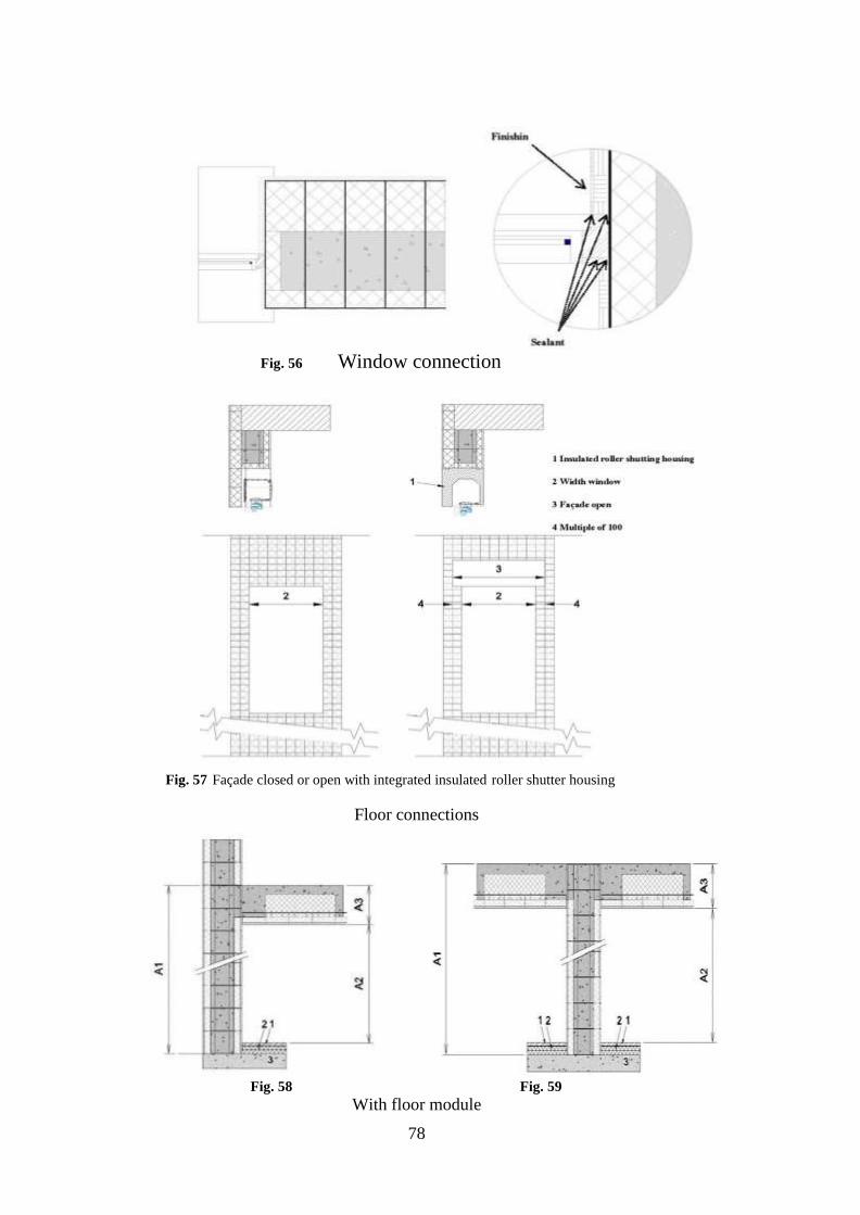
78
Fig. 56 Window connection
Fig. 57 Façade closed or open with integrated insulated roller shutter housing
Floor connections
Fig. 58 Fig. 59
With floor module

79
Fig. 60 Fig. 61
With self-bearing element and compressed layer
Fig. 62 Finishing on Stay in place EPS based double walled panel with in fill
concrete system foundation
Fig. 63 Finishing on existing foundation Underground Finishing

80
Annexure – 1b
MONOLITHIC CONSTRUCTION WITH STRUCTURAL STAY-IN-PLACE CR
STEEL SPECIALLY DESIGNED FORMWORK SYSTEM
ABOUT THE SYSTEM
Structural stay-in-place CR steel specially designed formwork system consist of
an integrated formwork with two filtering grids (panels) made of rib lath reinforced by
vertical stiffeners. These grids are connected by articulated. Rebar loops and connectors
that fold for easy transportation. The panels in various sizes are fabricated and assembled
in the factory. The construction work require accurate positioning of the form work
elements on the ground. After the erection of panels in alignment, closing of corners,
edges of door and window frames, rebar positioning, required reinforcement concrete of
Grade M25 is poured in the panels with a slump of around 12-18 cm. The concreting
may be done with a pump, bucket or with a shovel loader. The inside and outside walls
are finished with cement plaster of suitable grade. The painting of walls is to be done in
the conventional manner.
SPECIFICATIONS FOR PANELS SYSTEM ASSEMBLY COMPONENTS
a. Materials for rib mesh
Hot dip high galvanized steel in core as per ASTM A-653/A-653 M-00
Thickness : 0.42mm, Tolerance +0.04mm
180 GSM or 275 GSM Zinc coating depending upon the geological location to
prevent rusting of steel
Specification of steel:
o Tensile Strength - 305 Mpa- 415 Mpa
o Field point - 215 Mpa-450 Mpa
o Elongation - ≥ 31%
o Steel hardness - 50-60 rockwall hardness scale
Lock forming quality steel, zero spangle
b. Material for C- profile (vertical stiffeners)
Hot dip highly galvanized steel as per ASTM A-653/A-653 M-00
Thickness : 0.6 mm Tolerance +0.04mm

81
140 GSM or 180 GSM zince coating depending upon the geological location to
prevent rusting of steel
Specification of steel:
o Tensile Strength - 305 mpa- 415 mpa
o Field point - 250 mpa-450 mpa
o Elongation - ≥ 31%
o Steel hardness - 50-60 or rockwall hardness scale
Lock forming quality steel, zero spangle
Area of profile – 60.60 MM2 (i.e equivalent to 8 mm Ø bar)
Placed at every 200 mm C/C along width
c. Material for connector
Cold galvanized steel or CRCA
Thickness – 1.6 mm, Tolerance +0.1mm
Minimum 120 GSM zinc coated steel
Work as share link to connect steel on both faces of form work
Connects C profile & rebar
Help in preventing bulging of formwork during concreting
d. Material for Rebar
5 MM Ø Fe 240 grade Ms Bar
Placed at every 200 C/C or l00 Ø C/C
Dust free
PANEL SIZE
Width : 300mm, 500mm,700mm
900mm and 1100mm depending upon the size of room
Height : min 500 mm to max 4500 mm and multiple of 100mm
Thickness : 110 mm, 140mm, 160mm 200mm and 250mm depending upon
the

82
Structural design of the houses
CONCRETE
Minimum M 25 Grade concrete
REINFORCEMENT
As per the structure design (IS 456) to be provided by the bidder
FINISH
Cement plaster on both side as per the specification

83

84

85

86

87

88

89

90
Annexure – 1c
Light Gauge steel Framed Structure
Brief Description
Light Gauge Steel Framed Structure (LGFSS) is based on factory made galvanized light
gauge steel components produced by the cold forming method assembled as panels at site
forming structural steel framework of a building and varying wall and floor construction.
The panels are assembled on site with screws and bolts to form the internal and separating
walls and inner leaf of the external walls of a building and floors & ceiling. The building
is completed by the installation of an external layer of insulation material and outer leaf
of CP Board or dry mix shotcrete.
The system can incorporate all types of architectural features like coving, boxes,
cantilevers, projections, infill walls, mezzanine floors etc. This system can also
incorporate all types of services viz. electrical, gas and plumbing etc. The design and
engineering of the structures is executed by following the norms & guidelines stipulated
in relevant Indian Standards.
Typical section showing various components of Light Gauge steel Framed Structure is
illustrated in Fig. 1.
Fig. 1

91
Profile and Sizes of Framing Components
Table 1: Stud Profiles
Shape Width (Web) (mm) Flange Height (mm)
STUD
Thickness of 0.84, 1.2, 1.6 &
2mm in required cut size with
service slots, asper design &
requirement
EDGE
ANGLE
92.2 41.4
92.2 50.8
92.2 63.5
101.6 41.4
101.6 50.8
101.6 63.5
152.4 41.4
152.4 50.8
152.4 63.5
203.2 41.4
203.2 50.8
203.2 63.5
Table 1: Track Profiles
Shape Width (Web) (mm) Flange Height (mm)
TRACK
Thickness of 0.84, 1.2, 1.6 & 2mm
in required cut size with services slots, a
per design & requirement
ANGLE
96.8 63.5
106.2 63.5
157.0 63.5
207.8 63.5
258.6 63.5
309.4 63.5

92
Specifications for the System
Technical Specifications
Raw materials
Stud & track profiles shall be manufactured from pre-galvanized high tensile steel
conforming to IS 277:1992, ASTM A 653/A 653M-2013 Grade 350 having Yield stress
of min.350 MPa & Tensile stress of min. 380 MPa and coating of min. Z 275 or
equivalent as per the Performance requirement, Dimensions and Permissible tolerances
shall to ASTM C:955-07. See Fig 2 and table 3
Track shall be formed in a U-shaped configuration, having a depth compatible with that
of the studs of the same nominal size.
i. Min. height of track flanges shall be 19 mm. ii. Bracing and bridging shall have configuration and steel thickness to
provide secondary support for the studs in accordance with the relevant specifications for the Design of Cold-formed Steel Structural Members.
iii. Members shall be manufactured within the tolerance limits as shown in Fig.2 and Table 1 below
iv. The width of the board to which the sheathing board is attached shall not be less than 32 mm
Fig. 2 Manufacturing Tolerances

93
Table 3 Manufacturing Tolerances
Dimension Item Structural Stud (mm)
Structural Track (mm)
A Length + 2.38 -2.38
+ 12.7 - 6.35
B Web width + 0.79 - 0.79
+0.79 -3.18
C Flare overbend +1.59 -1.59
+0 -2.38
D Hole centre width +1.59 -1.59
NA
E Hole centre length +6.35
-6.35 NA
F Crown +1.59 -1.59
+1.59 -1.59
G Camber 0.79 12.7 max
0.79 12.7 max
H Bow 0.79 12.7 max
0.79 12.7 max
I Twist 0.79 12.7 max
0.79 12.7 max
MS plate shall conform to IS 2062:1999, E250
Other components
a) Heavy duty CP Board shall conform to IS 14862:2000 b) Gypsum board shall conform to IS 2095 (Part-1):2011 c) Gunniting/shotcreting d) shall conform to IS 9012:1978 e) Screws as per the details given below shall be used:
(i) Panel Assembly – Low profile screws (ii) LGS-LGS Wall panel to roof cassette – 12-14x15mm (iii) LGS to concrete – Tapcon screw 14-12x60mm Hex head (iv) Wire mesh = EPS board – SDS Hexhead with Ceresin without
washer (v) HRS-LGS – Hex heat (vi) CP board 6mm – WT 8 CSK Phillips (vii) Gypsum board – Flat heat self-driven type (viii) Deck sheet/Wire mesh – SDS WT, CSK, Flat head
Wire mesh – made of 4mm diameter wire of UTS 480 MPa of spacing 150x150 mm
or 1.4mm diameter of spacing 40x40mm
Rockwool slab having density 100 kg/m3 shall conform to IS 8183:1993

94
Rockwool roll with Aluminum foil having density 36 kg/m3 shall conform toIS
8183:1993
Erection & Fixing Process
Foundation
Foundations to light steel framing are essentially the same as for any other form of
construction, although the dead loads applied by the light steel frame will be much lower
than in concrete or masonry construction. The foundation line should be matched with
GFC drawings.
All forms of frame construction require an accurate ‘starting point’.
Therefore, the foundations or ground beams must be finished accurately in order to be
acceptable for ‘hand-over’ to the frame erector. For accurate erection of the frame, the
following tolerances are provided while in wide the engineering practice (SCI P301)
Length of wall frame +/- 10 mm in 10 m.
Line of wall frame +/- 5 mm from outer face of plate.
Level of base of wall frame +/- 5 mm over complete wall line
a) All tracks should completely rest on foundation to concrete.
b) Before doing any fabrication or erection careful site measurements should be
taken and any variations should be rectify.
c) The level should be maintained for foundation if there any level difference erection
can be done with insert plate and finally it should be grouted at the site.
Wall Panels
All load bearing studs, including king and jack studs, shall be seated in the tracks
with a maximum of 0.32 mm between the end of the stud and the web of the track.
Wall bridging shall use the same pattern of blocked bay at the end of each run
with additional intermediate blocked bays at 3.6 m on centre for lengths of walls
greater than 3.6 m. Wall bridging is not necessary if appropriate sheathing is
placed on both flanges of the stud prior to loading the wall.
Adequate temporary wall bracing shall be provided until permanent bracing has
been installed. Temporary construction bracing may also remain in place after
permanent bracing is installed.
A sill sealer, or equivalent, shall be provided between the undersides of the wall
when fastened directly to concrete.

95
During erection, support may be provided in sufficient number to prevent
distortion and damage to frame work due to wind or erection forces. These cables
may also be used to plumb and align the work.
All erection work must be level and to dimensions and elevations as indicated
by plans, using leveling instruments and plumb bob.
Report any discrepancies in plumbing or leveling to engineer in charge.
Make certain that, equipment of adequate capacity are available.
All the wall lines should be marked in the site.
Starting at any convenient external corner stand and plumb a wall frame panel in
its exact position.
Stand and plumb the adjoining frame to make a self-supporting corner.
Clamp the frames together and check again both the frames are in their exact
locations and standing vertical.
Connect the frames using the manufacturers recommended method.
Proceed with the erection of the frames around the house, standing internal and
external frames as they occur.
Provide adequate temporary bracing during wall frame erection. The line of top
plates in a run of walling should be checked with a string.
As-built tolerances for light steel framed structures
Light steel framing is very accurate and dimensional variations are largely due to the inaccuracy of the other components, particularly the foundations. Light steel framing may be used with all foundation types but care must be taken to ensure that target line and level tolerances are achieved, in order to assemble the wall panels accurately. Head of Stud Wall Overall Height
Plumb of stud wall:
Maximum deviation of +/-15mm in overall height of wall (3 storey) or +/- 10mm in
overall height of wall (2 storey) and +/- 5mm in storey height (approx. 2.5m)
Base of stud wall Verticality of frame (relative to base) Temporary bracing
Wall frames are unstable until floor members are fixed in position. As with any
type of building, it is unsafe practice to leave a partially erected structure in an
unstable state. Therefore, temporary side supports or bracing may be required,
particularly when the structure is left overnight in a partially erected condition.
The requirements of every individual case should be separately

96
considered but it may be appropriate to use a scaffold ‘cage’ for
extra restraint. The addition of other loads, such as stacking of
plasterboard on suspended floors, is not acceptable until the
framework has been completed and fully braced. These loads
should be checked by the designer.
Floor Panels
Follow in-line-framing layout when require
Use of string line, plumb bob, level, or transit is encouraged to ensure that the
foundation is relatively “true” before beginning installation because tolerances
are very critical in achieving an acceptable floor
Track members shall not be used individually for any load carrying applications
without an approved design.
Bearing surfaces for joists shall be uniform and level.
Adequate temporary joist bracing shall be provided until permanent bracing has
been installed. Temporary construction bracing may also remain in place after
permanent bracing is installed.
All anchors, hangers, tie-downs, bearing ledgers, etc., that are part of the
supporting structure shall be properly placed and attached. No steel joist shall
ever be installed on anchors or ties that have temporary connections to the
supporting structure.
Web stiffeners shall be installed at all concentrated load locations and are often
required at bearing points (i.e., where joists bear on bearing walls or beams)
unless designed otherwise.
Web stiffeners are permitted to be installed on either face of the joist web.
Floor joists shall not be loaded before bracing or sheathing is installed. Heavy
construction loads, such as stacks of plywood, gypsum board, bricks, etc., shall
not be placed on floor joists before they are properly braced or without
appropriately distributing the load so the capacity of the floor system is not
exceeded.
Walking across unbraced floor systems should be avoided. This may cause an
unexpected fall.
Sub-flooring should be checked for squeaks. Correct as necessary.
Allow a small gap on either end of the floor joist to keep the floor joist away from
the rim joist so that the potential problem of the floor joist rubbing against the
rim joist and causing squeaks in the floor is eliminated.
97
Roof Panels
The truss system is the most common roof system. The truss spacing is
determined by the type of roof cladding (i. e. tile or steel sheeting), the
strength and rigidity of the battens and safety guidelines for safe installation of cladding.
It is possible to increase this spacing if a ‘workmethod statement’ is developed to show it
is safe to install battens and cladding on trusses spaced further apart.
Truss chords typically use one of following sections:
Floor or roof trusses shall be engineered by a design professional.
Dimensions and proper bearing locations, as shown on truss design drawing, shall
always be verified before starting installation of the truss.
Temporary construction bracing shall remain in place as long as necessary for the safe
and acceptable completion of the roof or floor and may also remain in place after
permanent bracing is installed.
Trusses are laterally unstable until bracing is properly installed; necessary caution
shall be employed during the installation process. Overloading of roof trusses before
permanent bracing and/or sheathing is installed is not permitted.
Heavy construction loads, such as stacks of plywood, gypsum board, bricks, HVAC
units, etc., shall never be placed on trusses before they are properly braced. Trusses
are not typically designed for dynamic loads (moving loads). Sleepers for mechanical
equipment shall be located at panel points or over main supporting members, or on
trusses that have been designed to carry such loads.
Any corrections that involve cutting, drilling, or relocation of any truss member or
component shall not be made without notifying the truss manufacturer of the need for
and extent of the modifications. All major corrections, cutting, or drilling of truss
members without the approval of a qualified design professional shall be prohibited.
Trusses shall not be placed over loose lintels, shelf angles, headers, beams, or other
supporting structures not securely attached to the building.
Trusses that do not meet interior load bearing walls shall be shimmed for adequate
bearing.
Trusses shall not be pulled down to any interior partition.

98
Table 4 Minimum Allowable Fastener Capacity for Steel to Steel Connections1.2 [Safety factor = 3.0]
Screw
Size
Minimum
Shank Diameter
Minimum Head Diameter
Minimum Capacity (N)
Shear Capacity Pullout Capacity
1.10mm 0.84mm 1.10mm 0.84mm
No. 8 0.738 1.449 1098 738 423 324
No. 10 0.855 1.728 1183 796.5 490 378
1 Values represent the smaller thickness of two pieces of steel being connected.
2. Screw capacities given are calculated in accordance with CCFSS Technical Bulletin [25].
Decking Sheet
Thickness and profile of decking sheet shall be verified with the erection
drawings. These are normally used as temporary supports for the concrete till hardens.
Decking sheet has to be screwed to the joist with maximum spacing of 600 mm c/c for
uniform action of concrete and joist. All the joints of decking sheets longitudinal direction
requires a minimum lap of 100 mm.
Finishing of Wall
Walling materials such as CP board, Gypsum board, Gunniting /shotcreting& PPGI sheet etc.
when used for completing the wall internally & externally shall conform to the relevant
Indian Standards as applicable wall. Details of fixing of wall panels using these materials as
shown in Figs. 11 to 17 of Annex E may be referred for guidance.
Walling materials used in the system shall be such that the completed wall provides fire
resistant property as per requirements given in National Building Code 2005.
Cladding with GI Sheets
Thickness and profile of sheet shall be verified with the erection drawings. These are
normally used as roof/ wall cladding and design to resist wind load. Sheet has to be screwed
to the joist/ purlin with maximum spacing of 300 mm c/c. All the joints of sheets longitudinal
direction requires a minimum lap of 150 mm in order to make leak proof. Sealant tape/
sealant paste shall be used at joints to avoid any type of leakage
Structural drawings (Fig. 5 to 27) showing Erection & Fixing details of LGS Structure are
appended at Annex E.

99
The erection procedure for a light gauge steel frame used in housing is illustrated in Fig. 3
Fig. 3
M & E Services
Pre-punched service holes in the web of the steel frame allows electrical, gas and
plumbing services to be installed within the wall framing system. Plastic grommets and
silicone seals shall be used to fasten and protect wiring and pipes from corrosion and
damage arising from vibrations.
Electrical and Plumbing Services
Electrical and plumbing services are outside the scope of this Certificate; however, in
designing and installing these services, precautions must be taken to avoid the possible
risk of long term damage to the structure or the services by e.g. the ingress of water,
water vapour or condensation from water service pipes.
Electrical cables running within the insulation layer in the separating floor construction
should be protected with cartridge fuses or min circuit breakers.
Where it is necessary for fittings, services or ducts to penetrate a wall or floor
construction, the detailing must ensure that the relevant fire resistance, acoustic
performance and water &vapour resistance is not impaired, particularly in relation to the
fire integrity requirements

100
ANNEX A
(Clause 2.8.6)
ERECTION & FIXING DRAWINGS
TYPICAL ROOF DETAIL
SLOPED ROOF (PPGI She et & Gypsum Board)
Fig.4
JPIST SPACING
Normal spacing 305,407 and 610 mm
RIM
Normal spacing at end of panel
PANEL Dimension
Max Length 3.5 m, Max Height 5m and
Thickness as per design
PPGI SHEET SCREW
EACH JOIST:300 mm o/c
GYPSUM BOARD SCREW
EACH STUD 300 mm o/c

101
TYPICAL ROOF / FLOOR DETAIL
(Concrete Floor & Gypsum Ceiling)
Fig. 5
Joist Spacing
Normal spacing: 305, 407 &
610mm
Rim: Normal position at end
of panel
Panel Dimension: Max. length: 5.5m, Max. width:
3.5m, Thickness:As per
design
DECK SHEET SCREW
EACH JOIST 400mm o/c
GYSUM BOARD SCREW
EACH JOIST 300 o/c

102
s
TYPICAL WALL FRAME
WALL FRAME (WITH BRACE)
Fig. 6
Stud Spacing
Normal spacing: 305, 407 &
610mm
Noging: Normal, Position at middle of Panel Height
Panel Dimension
Max. length: 3.5m, Max. height: 5m, Thickness: 96mm
(o/o steel)
BRACE CONNECTION
BRACE ENDS 6 Nos
TAPCON SCREW
EACH STUD: 1 Nos
ANCHOR SHOE & BOLT
BRACE ENDS: 1 Nos

103
TYPICAL WALL FRAME
WALL FRAME (WITHOUT BRACE)
Fig. 7
Stud Spacing
Normal spacing: 305, 407 & 610mm Noging: Normal, Position at middle of
Panel Height
Panel Dimension
Max. length: 3.5m, Max. height: 5m,
Thickness: 96mm (o/o steel)
TAPCON SCREW
EACH STUD: 1 Nos

104
TYPICAL WALL FRAME
(WITH DOOR)
Fig. 8

105
TYPICAL WALL FRAME
(WITH WINDOW)
Fig. 9

106
TYPICAL WALL PANEL
INTERNAL WALL PANEL
(CP BOARD+GYPSUM BOARD IN BOTH SIDES)
Fig. 10
Stud Spacing
Normal spacing: 305, 407 & 610mm
Noging: Normal, Position at middle of Panel Height
Panel Dimension
Max. length: 3.5m, Max. height: 5m, Thickness: 96mm (o/o steel),133MM
(WITH FINISH)
TAPCON SCREW
EACH STUD: 1 Nos
CP BOARD SCREW
EACH STUD:300 mm o/c
GYPSUM BOARD SCREW
EACH STUD:300 mm o/c

107
TYPICAL WALL PANEL
INTERNAL WALL PANEL
(BOTH SIDE GYPSUM BOARD) Fig. 11

108
TYPICAL WALL PANEL
EXTERNAL WALL PANEL
(GUNNITING AND GYPSUM BOARD)
Fig. 12
Stud Spacing
Normal spacing: 305, 407 & 610mm Noging: Normal, Position at middle of
Panel Height
Panel Dimension
Max. length: 3.5m, Max. height: 5m,
Thickness: 96mm (o/o steel),137 MM
(WITH FINISH)
TAPCON SCREW
EACH STUD: 1 Nos
WIRE MESH SCREW
EACH STUD:600 mm o/c
GYPSUM BOARD SCREW
EACH STUD:300 mm o/c

109
TYPICAL WALL PANEL
EXTERNAL WALL PANEL
(PPGI SHEET AND GYPSUM BOARD)
Fig. 13
Stud Spacing
Normal spacing: 305, 407 & 610mm Noging: Normal, Position at middle of
Panel Height
Panel Dimension
Max. length: 3.5m, Max. height: 5m,
Thickness: 96mm (o/o steel),150 MM
(WITH FINISH)
TAPCON SCREW
EACH STUD: 1 Nos
PPGI SHEET SCREW
EACH STUD:300 mm o/c
GYPSUM BOARD SCREW
EACH STUD:300 mm o/c

110
TYPICAL WALL PANEL
EXTERNAL WALL PANEL
(PPGI SHEET& CP BOARD + GYPSUM BOARD)
Fig. 14

111
TYPICAL WALL PANEL
EXTERNAL WALL PANEL
(GUNNITING, CP BOARD AND GYPSUM BOARD)
Fig.15
Stud Spacing
Normal spacing: 305, 407 & 610mm Noging: Normal, Position at middle of
Panel Height
Panel Dimension
Max. length: 3.5m, Max. height: 5m,
Thickness: 96mm (o/o steel),140 MM
(WITH FINISH)
TAPCON SCREW
EACH STUD: 1 Nos
WIRE MESH SCREW
EACH STUD:600 mm o/c
GYPSUM BOARD SCREW
EACH STUD:300 mm o/c
CP BOARD SCREW
EACH STUD 300 mm O/C

112
TYPICAL WALL PANEL
WET WALL PANEL
(GUNNITING BOTH SIDE)
Fig. 16
Stud Spacing
Normal spacing: 305, 407 & 610mm Noging: Normal, Position at middle of
Panel Height
Panel Dimension
Max. length: 3.5m, Max. height: 5m,
Thickness: 96mm (o/o steel),155 MM
(WITH FINISH)
TAPCON SCREW
EACH STUD: 1 Nos
WIRE MESH SCREW
EACH STUD:600 mm o/c

113
TYPICAL ANCHORING
ANCHOR DETAIL AT INTERNAL WALL
Fig. 17

114
TYPICAL ANCHORING
ANCHOR DETAIL AT EXTERNAL WALL
Fig. 18

115
ANCHOR SHOE
HRS ANCHOR SHOE
Fig. 19

116
JOIST CONNECTION
JOIST PARALELL TO EXTERNAL WALL
Fig. 20

117
JOIST CONNECTION
JOIST PERPENDICULAR TO EXTERNAL WALL
Fig. 21

118
JOIST CONNECTION
INETRNAL LOAD BEARING WALL WITH TWO FlOOR CASSETTES
Fig. 22

119
JOIST CONNECTION
INTERNAL LOAD BEARING WALL FLOOR CASSETTES
Fig. 23

120
Fig 24

121
WALL TO WALL CONNECTION
TYPICAL DETAIL OF TWO WALL CONNECTION
Fig. 25
TWO WALL CONNECTION
WALL TO WALL CONNECTION
Fig. 25

122
TYPICAL LINTEL DETAIL
LINTEL PLATE FIXING DETAIL
Fig. 26

123
Annexure-2

124

125

126

127

128

129

130

131

132

133

134

135
DRAWINGS
(D1-D19)

1
3660
1500
59000
33080
55000
19400
3660
E
SN
W
520030001050
2500
2500
MH
5500
2500
700035
00
110 Ø PVC WASTE WATER PIPE
110 Ø PVC SWP
110 Ø PVC RWP
GT
MH
FT
FLOOR TRAP
GULLY TRAP
MANHOLE
LEGEND
PPR WATER PIPE FROM TANK
1200
2700
2500
900
ELECTRICAL POLE
PPR WATER PIPE FROMRINGMAIN TO OH TANK
SEWER LINE
DRAINAGE
WATER SUPPLY LINE
FIDDER PILLARFP

2
3660
1500
59000
33080
55000
19400
3660
E
SN
W
520030001050
2500
2500
2500
900

3
3660
1500
59000
33080
55000
19400
3660
E
SN
W
520030001050
2500
2500
MH
5500
2500
700035
00
1200
2700
2500
900

4
59000
33080
55000
19400
3660
E
SN
W
520030001050
2500
5600
7175
38030
7764
18000
48800
18200
2343
1923
25135

5
3660
1500
59000
33080
55000
19400
3660
E
SN
W
520030001050
2500
2500
2500
900
18624
13040
66006600
6600
3600

6
3660
1500
59000
33080
55000
19400
3660
E
SN
W
520030001050
2500
2500
2500
900

7
1000
5150
1350
1300
3800 1300 2000 1300 3800 1300
1350
5150
900
3200
7500
14800
80020
00
2000

8
1000
5150
1350
1300
3800 1300 2000 1300 3800 1300
1350
5150
900
3200
7500
14800
80020
00
2000

9
1300
3800
1300
1000
1350
1350
3800 1300 2600
3200
3200 1300
1000
1300
3800
1300
2000
4500
4950
2000
450015
0
1100
1233

10
UNITSL. TYPE SIZE CILL LVL. LIN.LVL. REMARK
DETAIL OF OPENINGSNO./
NO.
1300
3800
1300
1000
1350
1350
3800 1300 2600
3200
3200 1300
1000
1300
3800
1300
2000
4500
4950
2000
450010
00
1000
1000
1100
2400

11

12
3000
3000
3000

13
3000
3000

14
2500
450

15
3000
3000
3000
3000
3000
200
800
200
2100
1100
1000
900
1200
2100
3000
800
200
210011
0010
00
900
1200
2100
800
210011
0010
00
900
1200
2100
950
950
150021
00
900
150021
00
900
150021
00
900
2100
2100
2100
3000
3000
3000
3000
3000
2100
950
950
900
600
600 600
600

1630
0030
0030
00
3000
3000
950
3000
3000
200
800
210020
0 1100
2100
1000
3000
800
200
1000
1100
800
2100
1000
1100
150021
00
150021
00
150021
00
2100
2100
2100
2500
450
1500
3003
3000
150 15
015
015
0
900
600
600
3000
450

17

18

19